AksimentievGroup DepartmentofPhysicsand...
16
Aksimentiev Group Department of Physics and Beckman Institute for Advanced Science and Technology University of Illinois at Urbana-Champaign Building DNA Brick Structures with LegoGen Authors: Scott Michael Slone Chris Maffeo Chen-yu Li Aleksei Aksimentiev Contents 1 References 2 2 Introduction 2 2.1 Definition of Commands ....................... 2 3 Building the 3D model 3 3.1 Preferred CAD software ....................... 3 3.2 Using Blender to build models ................... 3 3.2.1 Template Design: Carving a Structure ........... 4 3.2.2 Basic Design: Converting a Sphere ............. 6 3.2.3 Advanced Design: Converting a Pillar ........... 6 4 Converting Models with LegoGen 7 4.1 Importance of Model Orientation .................. 10 4.2 Use of a Residue Mapping File and Preserving Sequences .... 10 4.3 Understanding Sequence Output .................. 12
Transcript of AksimentievGroup DepartmentofPhysicsand...

Aksimentiev GroupDepartment of Physics andBeckman Institute for Advanced Science and TechnologyUniversity of Illinois at Urbana-Champaign
Building DNA BrickStructures with LegoGen
Authors:Scott Michael SloneChris MaffeoChen-yu LiAleksei Aksimentiev
Contents
1 References 2
2 Introduction 22.1 Definition of Commands . . . . . . . . . . . . . . . . . . . . . . . 2
3 Building the 3D model 33.1 Preferred CAD software . . . . . . . . . . . . . . . . . . . . . . . 33.2 Using Blender to build models . . . . . . . . . . . . . . . . . . . 3
3.2.1 Template Design: Carving a Structure . . . . . . . . . . . 43.2.2 Basic Design: Converting a Sphere . . . . . . . . . . . . . 63.2.3 Advanced Design: Converting a Pillar . . . . . . . . . . . 6
4 Converting Models with LegoGen 74.1 Importance of Model Orientation . . . . . . . . . . . . . . . . . . 104.2 Use of a Residue Mapping File and Preserving Sequences . . . . 104.3 Understanding Sequence Output . . . . . . . . . . . . . . . . . . 12

1 REFERENCES 2
5 Preparation for simulations in NAMD 125.0.1 Elastic network model (ENM) constraints . . . . . . . . . 135.0.2 Energy minimization using NAMD . . . . . . . . . . . . . 13
5.1 Insertion of Mg-hexahydrate . . . . . . . . . . . . . . . . . . . . . 145.2 Solvation . . . . . . . . . . . . . . . . . . . . . . . . . . . . . . . 145.3 Extrabonds for MGHH stability . . . . . . . . . . . . . . . . . . . 155.4 Equilibration using molecular dynamics . . . . . . . . . . . . . . 15
6 Troubleshooting 166.1 When equilibration simulations crash . . . . . . . . . . . . . . . . 16
1 References
• Ke Y, Ong LL, Shih WM, Yin P (2012) Three-dimensional structuresself-assembled from DNA bricks. Science 338(6111):1177–1183.
• Yoo, J. & Aksimentiev, A., 2012, Improved Parametrization of Li+, Na+,K+, and Mg2+ Ions for All-Atom Molecular Dynamics Simulations ofNucleic Acid Systems, The journal of physical chemistry letters, 3(1), pp.45-50. http://dx.doi.org/10.1021/jz201501a
• Yoo, J., & Aksimentiev, A, 2013, In situ structure and dynamics of DNAorigami determined through molecular dynamics simulations. Proceedingsof the National Academy of Sciences of the United States of America,110(50), 20099-104. doi:10.1073/pnas.1316521110
• Li, C., Hemmig, E. A., Yoo J., Hernández-Ainsa, S., Keyser, U. F. &Aksimentiev A., Ionic conductivity and structural deformation of DNAorigami plates in electric field., ACS Nano, 2015, 9(2), pp. 1420-1433.http://dx.doi.org/10.1021/nn505825z
2 Introduction
In this tutorial, we will go through the steps for designing DNA structures usingthe DNA brick method. We will produce files for all-atom simulations of DNAbricks as well strand sequences for use in experimentation. DNA structures willbe built out of individual cubes known as Voxels, which have a side length of∼2.5 nm, or 8 base pairs.
2.1 Definition of Commands
If at any time you see an icon such as Shift , that means you need to pressthe appropriate key on your keyboard, in this case "Shift." If you see LMB ,

3 BUILDING THE 3D MODEL 3
MMB , or RMB , then you need to click the left, middle, or right mouse buttonrespectively.
3 Building the 3D model
3.1 Preferred CAD software
We use Blender (www.blender.org) to design the initial 3D model of our DNAbrick object, exported in VRML (.wrl) format. Tinkercad (www.tinkercad.com)can also be used to build CAD models exported in the VRML format, as well asany other CAD software that exports in the VRML format. Blender is integratedinto LegoGen’s interface, meaning no installations are required to use it withLegogen. We will discuss the use of Blender for building initial models.
3.2 Using Blender to build models
Screen Properties(Toggle with ‘n’)
Outliner
Tools Panel
3D View
Convert to .wrl
Figure 1: Blender Interface and Important Panels
Blender can either be downloaded through their website, the Steam dis-tribution platform, or used inside the LegoGen tool. Keep in mind different
3 BUILDING THE 3D MODEL 4
distributions of Blender will have slightly different appearances and interfaces,Fig. 1. This manual assumes you are using the version built into the LegoGentool.
To create structures for LegoGen, it is important to know certain rules andlimits to structure design, similar to 3D printing. If regions are made too thinthen DNA helices might not be properly connected to the main structure, andwould not form in experiment. The main rules to avoid this are to never buildstructures too thin and to avoid sharp edges. Keep the depth of a structureat least 5 nm (two helices or voxels) thick, and try to use gradual shifts ratherthan sharp edges.
We have several tutorials on how to build structures with LegoGen, depend-ing on your amount of skill with CAD software. If you are not very familiarwith CAD software and would prefer to rapidly build using a template, sev-eral templates are provided and their use is explained in Section 3.2.1. If youwould like to know how to build basic shapes such as spheres and cubes, and toconvert these simple structures with LegoGen, go to Section 3.2.2. If you wantto know how to build advanced structures made of numerous simple shapes,consult Section 3.2.3. If you would like a full understanding of the abilities ofLegoGen, please consult all three sections. If you feel you are familiar withbuilding models in Blender, please go ahead to Section 4 after you have made astructure.
If you have further questions about building with Blender there are numerousmanuals and tutorials for it, giving many ways to build structures as you wish.
3.2.1 Template Design: Carving a Structure
Included with this tutorial are several template files in "Templates andNAMD files/blender_templates.zip", which are collections of cubes that aresufficient for use in LegoGen. These files can be uploaded to the LegoGen in-terface by clicking on "Download Files" on the main LegoGen screen. Upload"10voxels_shrunk.blend" and load it into Blender by clicking "3D Shape Gen-eration", Fig. 2. You will already be in Edit mode, which can be toggled withTab . You can drag and rotate the structure with the MMB until its in theorientation you want. To build structures using this template you’ll need tocarve away unneeded cubes until the intended structure is visible. Each cuberepresents a single voxel of the DNA brick structure, which is approximately2.5 nm×2.5 nm×2.7 nm, with the longer helical axis being parallel to the Z-axis.
To delete individual cubes you will need to change your Select Type, whichspecifies what parts of the geometry you can select and modify. Choose all threeSelect Types (Vertex, Edge, and Face) by clicking all three while holding Shift

3 BUILDING THE 3D MODEL 5
View ControlSelect Types
Select ThroughStructure
Template Model
Figure 2: 10×10×10 template and important buttons for Template Design
. Now you can select all parts of the structure. To delete individual cubes youwill have to enter Select mode with C . Select a cube with the LMB and itwill highlight all parts of the structure inside the cursor. It is recommended tohighlight at least two nonadjacent vertices or faces, but is not always necessaryto remove the cube completely. If you accidentally highlight a portion you wishto preserve, you can deselect it with the MMB or by holding Shift while selecting.Once you’ve finished your selection delete it with Del and select "Faces" or goto "Delete" in the "Tools" tab. Your selection should be completely removed.
To carve all cubes in a specific row or column, we will need to change ourselection method again. Click "Select Through Structure" which is right of theSelect types. Normally you can only select from the visible portions of thestructure, but now you will select all portions of the structure that are insidethe circle, going through the structure. This can be very dangerous, letting youselect large portions of the template without realizing it. To prevent this, changethe View to the direction (Top, Front, Right, etc.) parallel to the intended rowso that accidental selections won’t be possible. Once you have made the intendedselection, delete as before.
As you carve the shape remember the physical distances you are workingwith. Each cube is 2.5 nm wide and is 2.7 nm tall, so initially the template is

3 BUILDING THE 3D MODEL 6
27×25×25 nm3. If you intend to make a structure that has a∼20 nm edge, you’dmake it 8 cubes wide. Remember the longest dimension of your structure interms of cubes, as you will need it in conversion. Once you have finished carvingthe template into the intended shape select "Export .wrl file for LegoGen." Youcan then exit or minimize Blender and proceed to the next step: conversion inSection 4. If you didn’t dramatically change the template’s edges, its longestdimension should still be 10 cubes.
3.2.2 Basic Design: Converting a Sphere
If you want to make a simple shape out of DNA, it is very easy to do. OpenBlender like in 3.2.1, and you will be presented with the initial Blender window,where only a default cube exists. Delete this cube, and create a sphere by goingto the Create Tab in the Tools Panel and selecting "UV Sphere." You can alsoselect a different geometric shape if you would prefer, but we will assume youselected the sphere. You may move the sphere around but this will not changehow the structure converts. Since the structure is so simple, it doesn’t need anymodifications, and is ready to convert to .WRL format. Select "Export .WRLfile for LegoGen" and proceed to Section 4.
3.2.3 Advanced Design: Converting a Pillar
More advanced structures cannot be made automatically, and can be tediousto carve using the template method. We will make a pillar shape 40 nm tall,28 nm thick at its base and top and 14 nm at the middle. In Blender’s units,we will consider 1 unit equal to 14 nm, although any conversion ratio can beused as long as you are consistent.. The helices in the structure will be parallelto the pillar’s orientation. To convert this into a DNA structure we must firstdetermine how many voxels long the structure will be in each direction. In thehelical direction, voxels are 2.7 nm thick, so the pillar will be 14.8 voxels tall,which we will round to 15. Any other direction the voxels are 2.5 nm wide,meaning the pillar’s thicknesses will be 11 and 5 voxels respectively. Rememberthe longest of these values, 15, its orientation to the helical axis, parallel, forlater.
Delete the default cube as in previous sections, and change the viewingorientation to "Front." First, we will build the base of the pillar. Create a conefrom the Create tab of the Tools Panel. There will be a panel in the lower leftcalled "Add Cone" that will let you change properties of the cone. Change itsdepth to .5, Radius2 to .5 and its location to (0,0,.25). Duplicate the cone withShift-D and place it at (0,0,1.75) and rotate it 180 degrees along the Y axis. Torotate or move already generated shapes you need to open the Screen Propertiespanel with N . The bases of the cylinder are nearly done.
4 CONVERTING MODELS WITH LEGOGEN 7
Next we will make the cylindrical portions of these bases. This is so thebases do not have sharp edges that might convert incorrectly. Create a cylinderand change its depth to .25 and location to (0,0,-.125). Either duplicate orcreate an identical cylinder and place it at (0,0,2.125). The bases of the pillarare complete. Create a new cylinder with different dimensions (Radius .5 andDepth 1) at (0,0,1). The pillar is now complete.
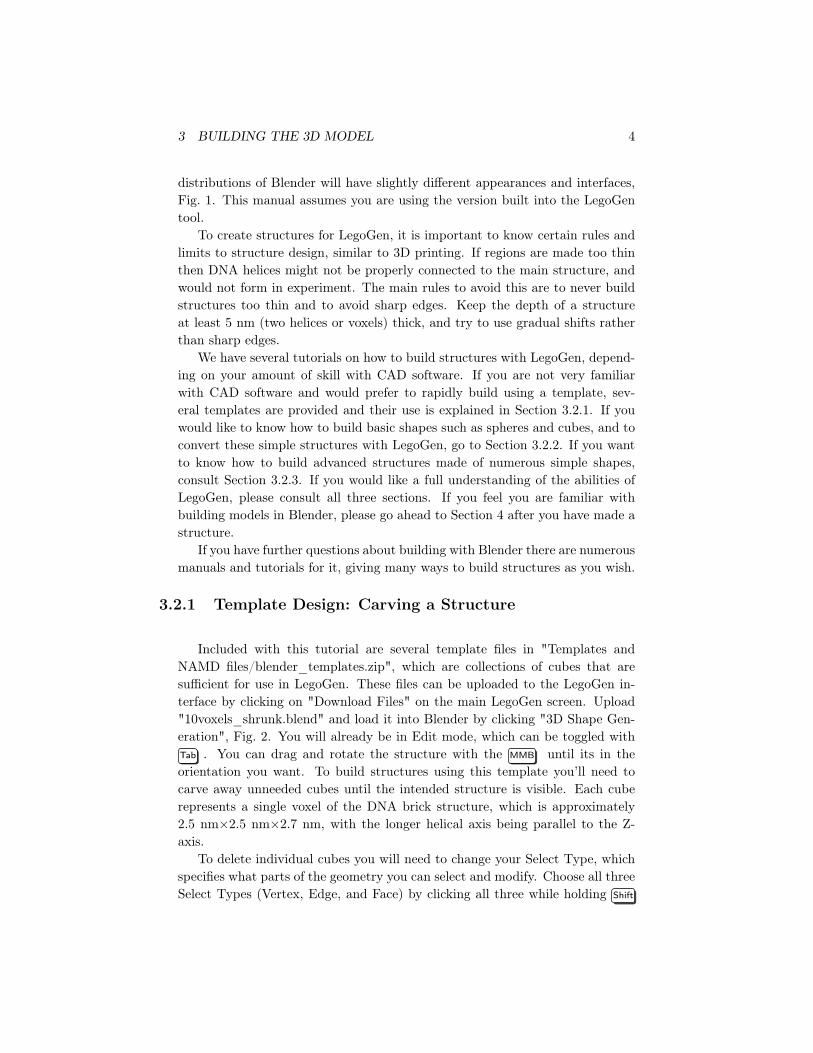
We will now join the portions of the pillar together and remove redundantfaces. Select all portions of the structure by holding Shift while selecting themin the Outliner, Fig. 1. Join them together by selecting "Join" in the Tools tabof the Tools Panel. The overall shape of the structure pillar is now complete,Fig. 3A, but it is not yet ready to convert. If you attempt to voxelize thestructure, like in Section 3.2.2, the structure might have large holes or potentiallyportions of it missing.
Figure 3: Completed Pillar
Enter Edit Mode and select all vertices with A . Select "Remove Doubles"in the Tools tab, and redundant vertices that were shared between adjacentshapes will be removed. However, the faces shared between shapes still exist asinternal faces. These can easily be removed by going to Select in the lower rightand selecting "Interior Faces." Delete what Blender selects and all interior faceshave been removed. The structure can now be sent to LegoGen. Remember thedistance in the longest direction, 15 voxels, and its orientation, parallel to thethe helical axis, and proceed to Section 4.
4 Converting Models with LegoGen
Once your models are in WRL format they can be converted to a DNA brickmodel with LegoGen, Fig. 4. The only requirements are your converted WRL

4 CONVERTING MODELS WITH LEGOGEN 8
Figure 4: LegoGen conversion interface.
file and parameters you will enter now, with an optional residue map (resmap)file if you wish to use strands from a strand library. The important factor inconversion is the box size, which will affect both the size of our structure and howwell its resolved in DNA bricks. A voxel unit is equal to 2.5 nm×2.5 nm×2.7 nm,with the longer end oriented with the DNA helix inside the voxel. Changing thebox size changes the number of voxels in each direction. For example, with ourinitial sphere, a box size of 6 will make a sphere with approximate dimensionsof 15 nm×15 nm×16.2 nm, so the sphere will be slightly longer in the helicaldirection. Doubling the box size will in turn double the size of the sphere in eachdirection. However, it is difficult to think in voxels rather than physical units ofdistance. To use physical units of direction we also must take the direction ofthe box size into account. Take the pillar from Section 3.2.3 for example. Thepillar is intended to be 40 nm tall and 28 nm at its widest. The longest directionwould be 40 nm, which is parallel to the helical axis. The orientation mattersbecause the voxel is longer in the parallel orientation, meaning the pillar is 14.8or 15 voxels tall. If it were longest in a non-helical direction, and 40 nm, thenit would be exactly 16 voxels tall.
Remember from some of our earlier models that the box sizes that were used.If you used the recommended template from Section 3.2.1 and didn’t change its

4 CONVERTING MODELS WITH LEGOGEN 9
maximum dimension, then you will have a box size of 10. For our pillar fromSection 3.2.3, its 15. For the sphere from Section 3.2.2, we didn’t specify a sizeinitially, so you can scale the size as you wish. Keep in mind the maximum sizefor structures is 32 voxels, or 80 nm. Enter in the appropriate box size for yourstructure.
Next we can select whether to produce a blunt structure or a strand mini-mized structure. In a blunt structure, all DNA will be double-stranded, and 8nt strands will be generated. This will produce a lot of strands, but there will beno exposed nucleotides. In a strand minimized structure, no 8 nt strands will beproduced and additional connections will be made to make the average strandlength at the edges longer. The structure will also have a buffer of 8 nt frag-ments of thymine on end strands, making the structure dimensions potentiallylarger than expected. Select the version of the structure you would prefer.
Next we will select our CAD model file. If your model was converted to WRLthrough the built-in version of Blender, select "Blender File" as the model touse. If bringing in a file externally, select "Upload." If you would like an examplestructure built, there is one available of Link from The Legend of Zelda. Thismodel looks best at a box size of 16–32, although it is likely too complex to beable to be created practically.
Lastly, we can select a residue file, or resmap. Residue maps record thepositions of nucleotides in the structure, allowing for different structures toshare sequences if the same resmap is used. If you have one you may upload itnow. If you don’t there are two example residue maps, or if you select "Don’tuse a residue map" one will be generated for you.
You can switch "Visualize Output" to yes to get a glimpse of your producedstructure in VMD before it saves. This will let you see if the structure was whatyou intended. If it isn’t, you can easily go back to Blender and modify it as youplease. If your intent is to use LegoGen for simulations, the structures can beminimized to streamline that step of simulation. Flip the "Run Minimization"switch to Yes to add this to conversion.
Once all files and inputs are selected, press "Convert" to start. The file willbe automatically converted into DNA bricks, and can be downloaded afterwardsin a compressed format. A list of sequences and the residue map used are alsoprovided. Your structure is now ready to be created in a DNA self-assemblyreaction or simulated in NAMD. The remaining portions of this section dealwith specific advanced topics of conversion. If you are going to need to read thesequence list, go to 4.3. If you have built the structure you intended and wishto simulate your structure in NAMD, go to 5.

4 CONVERTING MODELS WITH LEGOGEN 10
A B C
Figure 5: Converted Structures using Blunt Method. A. Converted Sphere. B.Converted pillar. C. Converted pillar with an extra rotation.
4.1 Importance of Model Orientation
It is important to keep track of the effects of orientation of the model on con-version. The sphere was largely independent of orientation, and converted to agenerally spherical shape made of DNA strands, Fig. 5A. For the more complexpillar, there are notable effects from orientation. Depending on the orientation,the pillar’s overall length might change. For the pillar exactly as it is in thetutorial, the helices are oriented to the direction of the pillar, with the heads ofthe DNA bricks oriented towards the base of the pillar, Fig. 5B. When the modelwas rotated 90 degrees in the Y direction, the structure looks visibly different,Fig. 5C. The structure is slightly shorter and stretched in the direction of thehelices, caused by the fact that the voxels are slightly longer in the helical axis.Keep in mind these differences in orientation might cause your structure to bedrastically different both in appearance and mechanics. The two pillars, whilehaving the same overall shape, would behave differently when in tensile or com-pressive stress. Also keep in mind that in some CAD programs, the definitionof orientations can be different, so if you have a preferred CAD software keepthis in mind when converting.
4.2 Use of a Residue Mapping File and Preserving Se-quences
A residue map preserves the sequences of strands associated with specific voxelsBy making minor changes that do not change the overall dimensions or numberof voxels used, it is possible to reuse the same sequences for different structures,preserving the core structure. This can be of use if, for example, several cubicalstructures were designed with the same core shape, Fig. 6A, but each had dif-ferent extensions or internal changes without changing the overall shape, then

4 CONVERTING MODELS WITH LEGOGEN 11
A B C D
Figure 6: Representative cubes with different bounding voxel amounts. A. 3voxels. B. 3 voxels. C. 4 voxels, due to the addition, but no shift in coresequences. D. 4 voxels, but a shift in core sequences
the unchanged strands would be identical between structures. Keep in mindthis is dependent on several factors. If a structure is changed by the removalof sections, Fig. 6B, then there is no change to the overall mapping of strandsand the strands in remaining sections will be identical If a structure has a largeextension is added to it, the voxel box size will need to be changed and theunchanged regions may not be identical. It depends largely on the directionthe addition is made. If the direction is made in the negative X direction orthe positive Y or Z direction in Blender, then the overall structure will not bedramatically shifted and strand sequences will be identical, Fig. 6C. If it is inthe opposite directions then there will be some differences in strands, Fig. 6D.
Residue map files can be changed directly if specific nucleotides are intendedfor selected regions of a structure. Residue map files are a list of coordinatesand the nucleotide associated with those coordinates. The first 3 coordinatescorrespond to the voxel location, the fifth is the base pair in the nucleotide chainof the helix in that voxel, with 0 being the base pair closest to the negative-Xside of the voxel and 7 being the base pair closest to the positive-X side. Thefourth location is which of the nucleotides in that base pair is selected, with 0being the nucleotide with its 3’ end pointed to the negative-X side of the voxeland 1 being the nucleotide with its 3’ end to the positive-X side of the voxel.

5 PREPARATION FOR SIMULATIONS IN NAMD 12
4.3 Understanding Sequence Output
The three outputs of the conversion will be the PDB and PSF files for use insimulations, the residue map file for future conversions, and a list of sequencesused. The list of sequences per strand are paired with a sequence coordinate(0001, 0002, 0003, etc.), and a similar looking serial number (00019, 0002F,000311, etc.). The sequence coordinate is that strands specific position in thestructure. The first three are its coordinates in voxels and the last it is strandnumber. These can be specifically selected for viewing by opening the PDBand PSF files in VMD and selecting them with "segname ’<coordinates>’" inGraphical Representation. The single quotation marks around the coordinatesare important, as a coordinate of "0001" might be read as the number "1." Thesingle quotation marks preserve your selection as a string. In structures withminimal differences, strands with identical coordinates should have identical orsimilar sequences, but to verify this we look at the serial number. If a struc-ture’s dimensions have been shifted, as warned about in the previous section,then there is a chance they will not be comparable. Be careful when buildingstructures to avoid this if the goal is to preserve certain sequences.
The serial number, the second column, shares the first 3 digits with thesequence coordinate, but the rest will be unique to that strand. If two strandsin a structure have the same serial number, they will have the same sequence.This lets you maintain a library of strands by their serial numbers, rather thanhaving to look by sequence. This can also help you verify that your structure isas intended, and you didn’t accidentally shift the structure as warned, as mostof your serial numbers should still be the same. Once you’ve converted yourstructure, if you already have a library of strands defined by serial number, youcan simply select them from the list and proceed with experiments! If you aremore interested in simulation, please proceed to Section 5 below.
5 Preparation for simulations in NAMD
Now that our DNA structure has been generated, it needs to be prepared forsimulation through several steps. Elastic constraints, minimization, and theaddition of water and ions to the system are just some of the required steps.We will first apply constraints to the DNA bases for use in minimization andinitial equilibration. We will assume you are using the structure generated fromthe Basic Design tutorial, and will refer to our PSF and PDB files as sphere.pdband sphere.psf, respectively.

5 PREPARATION FOR SIMULATIONS IN NAMD 13
5.0.1 Elastic network model (ENM) constraints
Because we want to optimize only the DNA backbone conformations, we needto apply restraints to protect the DNA base conformations. In this tutorial, weadd inter-nucleotide harmonic distance constraints between base heavy atomswithin 8 Å using extrabonds functions in the NAMD package. See NAMD man-ual for details of extrabonds (e.g., http://www.ks.uiuc.edu/Research/namd/2.7/ug/node26.html). Because this approach resembles the elastic networkmodel (ENM), we term this the ENM constraint. We provided a perl script(pdb2enm.pl) for generating extrabonds between base heavy atom pairs. Thefollowing command will take sphere.pdb as an input to generate sphere.enm.extrafile that contains extrabonds entries. Note that we used a cutoff of 8 Å and aforce constant of 0.5 kcal/mol/Å2, which can be changed depending on the inputsystem.
perl pdb2enm.pl --namd --k=0.5 --cut=8 sphere.pdb > sphere.enm.extra
Or using a tcl version (this may take a few minutes):
vmd -dispdev text -e pdb2enm.tcl -args 0.5 8 sphere.pdb sphere.enm.extra
5.0.2 Energy minimization using NAMD
Now we are ready to perform energy minimization using the prepared files. Ifyou already minimized inside the LegoGen tool you may skip this step. Weprovided a sample NAMD input configuration file (mini.namd) that can beused to optimize the DNA backbone conformation. The extrabonds functionare invoked by the following lines in the mini.namd.
extraBonds onextraBondsFile sphere.enm.extra
Run NAMD by typing the following command on the terminal (this maytake a few minutes):
namd2 mini.namd > mini.log &
This simply performs an energy minimization for 1,000 steps and writes thefinal conformation to a file named sphere.mini.coor. One can confirm thatcrossover conformations are optimized by loading the resulting coordinate file

5 PREPARATION FOR SIMULATIONS IN NAMD 14
to VMD. To save the final conformation as a new PDB, sphere_mini.pdb, runthe following line:
vmd -dispdev text -e mini_saveLast.tcl
5.1 Insertion of Mg-hexahydrate
Next, we would neutralize the DNA brick system with Mg-hexahydrate (MGHH)molecules. Mg parameters of the standard CHARMM force field result in ar-tificially condensed phase of DNA as demonstrated in our reference (Yoo andAksimentiev, JPCL, 2012). Thus, an improved model of Mg in the form of Mg-hexahydrate is essential for DNA structures as demonstrated in our reference(Yoo and Aksimentiev, PNAS, 2013).
Because Mg-hexahydrate molecules diffuse slowly, if we place them far fromthe DNA bricks, we would spend a lot of time waiting for Mg-hexahydratemolecules to diffuse into the DNA brick structure. So, we would use a customizedscript to place Mg-hexahydrate molecules close to the DNA brick strands. Runthe following command in the terminal:
vmd -dispdev text -e add_mgh_ver2_3.tcl -args sphere_minisphere_MGHH 516
The first argument “sphere_mini” is the prefix for the input psf and pdb files,which you can change to “sphere” if you minimized inside LegoGen. The secondargument “sphere_MGHH” is the prefix for the output psf and pdb files. Thelast argument “516” is the number of Mg-hexahydrate molecules to be added,which should be adjusted depending on the size of the final simulation box andthe desired concentration. If you intend to neutralize keep in mind each strandwill have a charge equal to the number of nucleotides plus 1.
5.2 Solvation
In reality, DNA brick structures are always prepared in solution. So, to simulatethe sphere in a experimental condition, we need to put the sphere in solution.The solIon.tcl is used for solvating the system in water and adding Cl− ions.Running the following command
vmd -dispdev text -e solIon.tcl
would produce the final solvated sphere system (sphere_MGHH_WI.psf and sphere_MGHH_WI.pdb).Note that the number of monovalent ions can be adjusted by modifying solIon.tcl.

5 PREPARATION FOR SIMULATIONS IN NAMD 15
5.3 Extrabonds for MGHH stability
Usually Mg-hexahydrate structure is so strong that the structure is stable withno constraints in a normal condition. However, the MGHH structure can beeasily broken at the beginning of the DNA brick simulation because of largeCoulombic forces between DNA and Mg due to charge imbalance. Thus, weadd extrabonds constraints between Mg and water oxygen in MGHH to pre-vent undesired dissociation of MGHH. mghh_extrabonds.pl script will generateextrabonds definitions for NAMD.
perl mghh_extrabonds.pl sphere_MGHH_WI.pdb > mghh_extrabonds
Or, you can use the tcl version:
tclsh mghh_extrabonds.tcl sphere_MGHH_WI.pdb> mghh_extrabonds
In NAMD script, the following lines are needed.
extraBonds onextraBondsFile ./mghh_extrabonds
5.4 Equilibration using molecular dynamics
Equilibrating the DNA brick system is not a trivial task. There are two mainfactors which could break local DNA brick structure. One of them is the elec-trostatic repelling force between the backbones of the DNA strands. The otheris the torsion at the heads of the DNA bricks. To avoid breaking the base-pairswhile relaxing the global structure, we simulate the sphere with ENM constraintsand gradually reduce the force constant. The following protocol will simulatethe sphere with ENM constraints with k = 0.5, 0.1, 0.01 and 0 (kcal/mol/Å2)continuously. Each simulation is 4.8 ns. Although this protocol applies to mostsmall- to medium-sized DNA structures, the users may need to modify it fortheir own brick structures, especially larger structures at the limits of LegoGen’sbox size. First, run the following command to generate ENM extrabonds fileswith 3 different force constants:
./mk_extra.sh
For k = 0, we simply turn off the ENM constraints.Then, run the simulations one after another:

6 TROUBLESHOOTING 16
namd2 equil_k0.5.namd > equil_k0.5.log &
namd2 equil_k0.1.namd > equil_k0.1.log &
namd2 equil_k0.01.namd > equil_k0.01.log &
namd2 equil_k0.namd > equil_k0.log &
Once your structures have equilibrated through all steps you are ready toproceed with any other simulations you intend to do. Look at the trajectory tomake sure the structure has relaxed as intended, and that the MGHH moleculeshave penetrated the DNA brick structure.
6 Troubleshooting
6.1 When equilibration simulations crash
At the beginning, the system can be unstable. You need to check total energy.If total energy looks fine and your system is still unstable, you might try:
• Decreasing the timestep
• Turn off pressure coupling; do NVT.
Somehow both genbox and solvate put significantly less number of water in abox, resulting in bubbles in the box after equilibration in NVT.
Solutions:1. Resolvation after equilibration.2. NPT with DNA fixed.When a DNA brick object is large, the number of inserted water molecules
can be underestimated, causing a bubble after a short equilibration. Bubblesof moderate size can be removed by simply equilibrating under NPT ensemble.Sometimes large bubbles can cause abrupt change in box size, resulting in aninstability of MD simulations. In this case, increasing langevinPistonPeriodand langevinPistonDecay by a factor of 10 can be helpful. By changing theseoptions, we make changes in box size less responsive to the internal pressure tomake the MD simulation more stable. After the box size becomes stabilized,those options can be reverted to the default values.


![r Pages 685-720 CREO Lesson 16 Gary€¦ · A helical sweep (Fig. 16.1) ... the section geometry of the spring at the intersection of the crosshairs [Fig. 16.5(f)] > MMB > LMB > select](https://static.fdocuments.in/doc/165x107/5b155dc87f8b9ac7128c0d9c/r-pages-685-720-creo-lesson-16-a-helical-sweep-fig-161-the-section-geometry.jpg)


![[SBA] [MMB] [Nov] [2009]](https://static.fdocuments.in/doc/165x107/55cf8e2b550346703b8f4c94/sba-mmb-nov-2009.jpg)