AKR/AKRS - KSB · Weld grooves:DIN EN ISO 9692-1 (1.3 + 1.5) Different designs of butt weld ends...
12
Swing Check Valve AKR/AKRS PN 63-160 DN 80/80 to 300/250 Type Series Booklet
Transcript of AKR/AKRS - KSB · Weld grooves:DIN EN ISO 9692-1 (1.3 + 1.5) Different designs of butt weld ends...

Swing Check Valve
AKR/AKRS
PN 63-160DN 80/80 to 300/250
Type Series Booklet

Legal information/Copyright
Type Series Booklet AKR/AKRS
All rights reserved. The contents provided herein must neither be distributed, copied, reproduced,edited or processed for any other purpose, nor otherwise transmitted, published or made available to athird party without the manufacturer's express written consent.
Subject to technical modification without prior notice.
© KSB SE & Co. KGaA, Frankenthal 17/01/2018

Contents
Check Valves and Strainers .............................................................................................................................. 4Swing Check Valves to DIN/EN .................................................................................................................................................. 4
AKR/AKRS ............................................................................................................................................................................. 4Main applications........................................................................................................................................................... 4Fluids handled ................................................................................................................................................................ 4Operating data............................................................................................................................................................... 4Body materials................................................................................................................................................................ 4Design details ................................................................................................................................................................. 4Product benefits ............................................................................................................................................................. 4Related documents ........................................................................................................................................................ 4Purchase order specifications ........................................................................................................................................ 5Pressure/temperature ratings ........................................................................................................................................ 5Materials ......................................................................................................................................................................... 6Dimensions and weights................................................................................................................................................ 7
Contents
3
Check Valves and StrainersSwing Check Valves to DIN/EN
4 AKR/AKRS
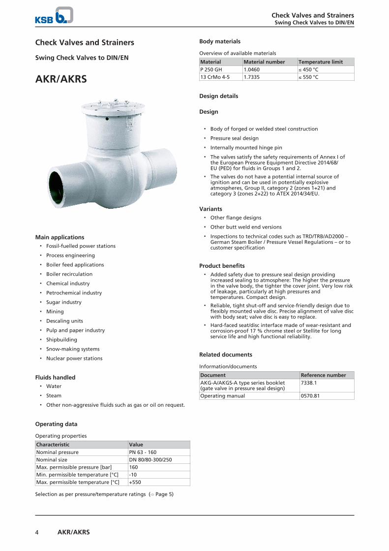
Check Valves and Strainers
Swing Check Valves to DIN/EN
AKR/AKRS
Main applications▪ Fossil-fuelled power stations
▪ Process engineering
▪ Boiler feed applications
▪ Boiler recirculation
▪ Chemical industry
▪ Petrochemical industry
▪ Sugar industry
▪ Mining
▪ Descaling units
▪ Pulp and paper industry
▪ Shipbuilding
▪ Snow-making systems
▪ Nuclear power stations
Fluids handled▪ Water
▪ Steam
▪ Other non-aggressive fluids such as gas or oil on request.
Operating data
Operating properties
Characteristic ValueNominal pressure PN 63 - 160Nominal size DN 80/80-300/250Max. permissible pressure [bar] 160Min. permissible temperature [°C] -10Max. permissible temperature [°C] +550
Selection as per pressure/temperature ratings (⇨ Page 5)
Body materials
Overview of available materials
Material Material number Temperature limitP 250 GH 1.0460 ≤ 450 °C13 CrMo 4-5 1.7335 ≤ 550 °C
Design details
Design
▪ Body of forged or welded steel construction
▪ Pressure seal design
▪ Internally mounted hinge pin
▪ The valves satisfy the safety requirements of Annex I ofthe European Pressure Equipment Directive 2014/68/EU (PED) for fluids in Groups 1 and 2.
▪ The valves do not have a potential internal source ofignition and can be used in potentially explosiveatmospheres, Group II, category 2 (zones 1+21) andcategory 3 (zones 2+22) to ATEX 2014/34/EU.
Variants▪ Other flange designs
▪ Other butt weld end versions
▪ Inspections to technical codes such as TRD/TRB/AD2000 –German Steam Boiler / Pressure Vessel Regulations – or tocustomer specification
Product benefits▪ Added safety due to pressure seal design providing
increased sealing to atmosphere: The higher the pressurein the valve body, the tighter the cover joint. Very low riskof leakage, particularly at high pressures andtemperatures. Compact design.
▪ Reliable, tight shut-off and service-friendly design due toflexibly mounted valve disc. Precise alignment of valve discwith body seat; valve disc is easy to replace.
▪ Hard-faced seat/disc interface made of wear-resistant andcorrosion-proof 17 % chrome steel or Stellite for longservice life and high functional reliability.
Related documents
Information/documents
Document Reference numberAKG-A/AKGS-A type series booklet(gate valve in pressure seal design)
7338.1
Operating manual 0570.81
Check Valves and StrainersSwing Check Valves to DIN/EN
5AKR/AKRS
Purchase order specificationsPlease specify the following information in all enquiries orpurchase orders:
1. Type
2. Nominal pressure
3. Nominal size
4. Operating pressure
5. Differential pressure
6. Operating temperature
7. Material
8. Fluid handled
9. Flow rate
10. Pipe connection
11. Variants
12. Reference number
Always indicate the original serial number and the year ofconstruction when ordering spare parts.
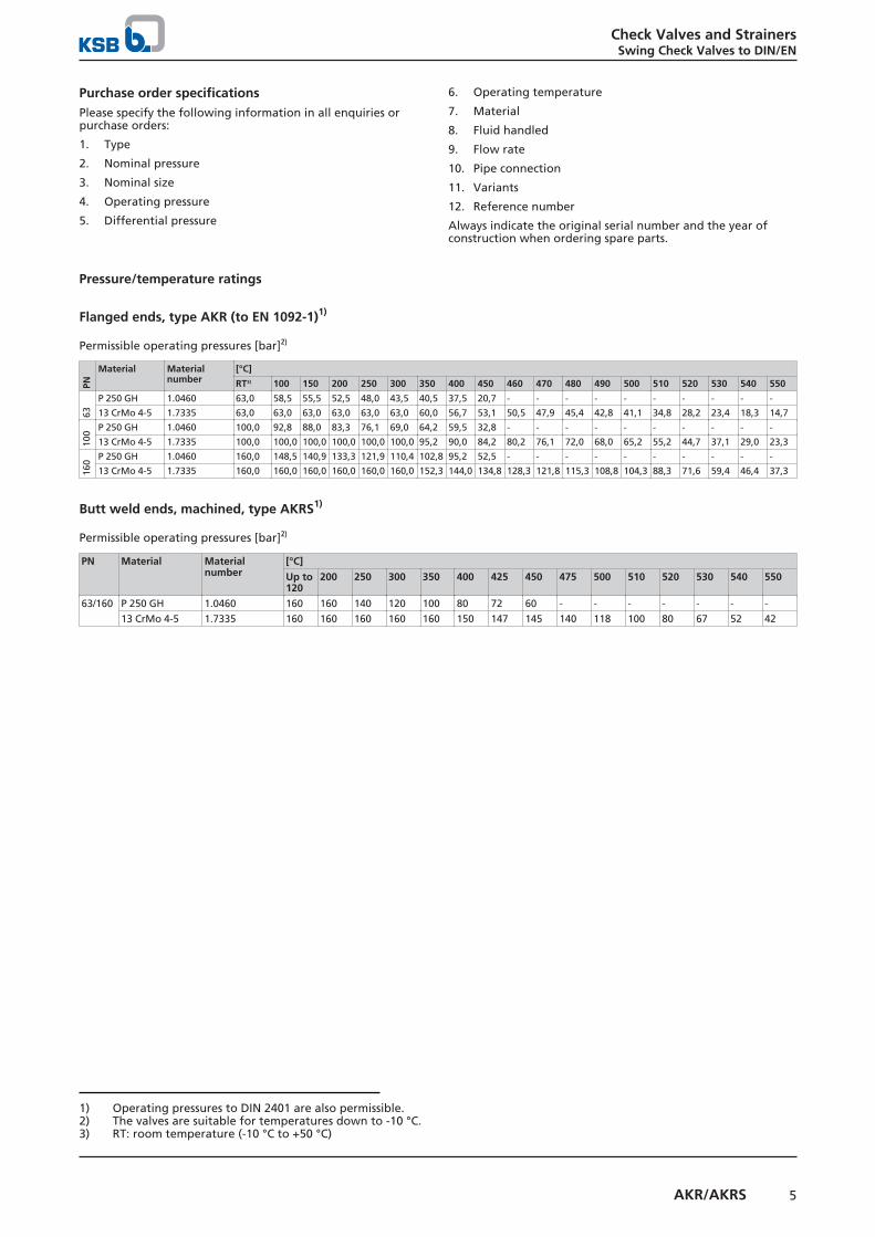
Pressure/temperature ratings
Flanged ends, type AKR (to EN 1092-1)1)
Permissible operating pressures [bar]2)
PN
Material Materialnumber
[°C]
RT3) 100 150 200 250 300 350 400 450 460 470 480 490 500 510 520 530 540 550
63
P 250 GH 1.0460 63,0 58,5 55,5 52,5 48,0 43,5 40,5 37,5 20,7 - - - - - - - - - -
13 CrMo 4-5 1.7335 63,0 63,0 63,0 63,0 63,0 63,0 60,0 56,7 53,1 50,5 47,9 45,4 42,8 41,1 34,8 28,2 23,4 18,3 14,7
100 P 250 GH 1.0460 100,0 92,8 88,0 83,3 76,1 69,0 64,2 59,5 32,8 - - - - - - - - - -
13 CrMo 4-5 1.7335 100,0 100,0 100,0 100,0 100,0 100,0 95,2 90,0 84,2 80,2 76,1 72,0 68,0 65,2 55,2 44,7 37,1 29,0 23,3
160 P 250 GH 1.0460 160,0 148,5 140,9 133,3 121,9 110,4 102,8 95,2 52,5 - - - - - - - - - -
13 CrMo 4-5 1.7335 160,0 160,0 160,0 160,0 160,0 160,0 152,3 144,0 134,8 128,3 121,8 115,3 108,8 104,3 88,3 71,6 59,4 46,4 37,3
Butt weld ends, machined, type AKRS1)
Permissible operating pressures [bar]2)
PN Material Materialnumber
[°C]
Up to120
200 250 300 350 400 425 450 475 500 510 520 530 540 550
63/160 P 250 GH 1.0460 160 160 140 120 100 80 72 60 - - - - - - -
13 CrMo 4-5 1.7335 160 160 160 160 160 150 147 145 140 118 100 80 67 52 42
1) Operating pressures to DIN 2401 are also permissible.2) The valves are suitable for temperatures down to -10 °C.3) RT: room temperature (-10 °C to +50 °C)

Check Valves and StrainersSwing Check Valves to DIN/EN
6 AKR/AKRS
Materials
AKR AKRS
Parts list
Part No. Description Temperature[°C]
Material Material number Note
100 Body ≤ 450 °C P 250 GH 1.0460 Body die-forged and welded≤ 550 °C 13 CrMo 4-5 1.7335
723 Flange ≤ 450 °C P 250 GH 1.0460 -≤ 550 °C 13 CrMo 4-5 1.7335
131.1 Connection branch ≤ 450 °C P 250 GH 1.0460 Material can be matched topipeline material.≤ 550 °C 13 CrMo 4-5 1.7335
7464) Valve disc ≤ 450 °C P 250 GH 1.0460 -≤ 550 °C 13 CrMo 4-5 1.7335
139 Bonnet ≤ 450 °C P 250 GH 1.0460 -≤ 550 °C 13 CrMo 4-5 1.7335
Seat/discinterface
Body ≤ 450 °C Hard-faced 1.4115 Hard-faced≤ 550 °C Stellite hard-
faced-
Valve disc ≤ 550 °C Stainless steelhard-faced
1.4370
4114) Joint ring ≤ 550 °C Pure graphite - -
501 Segmental ring 13 CrMo 4-5 1.7335 -570 Hanger arm 13 CrMo 4-5 1.7335 -
4) Recommended spare parts
Check Valves and StrainersSwing Check Valves to DIN/EN
7AKR/AKRS
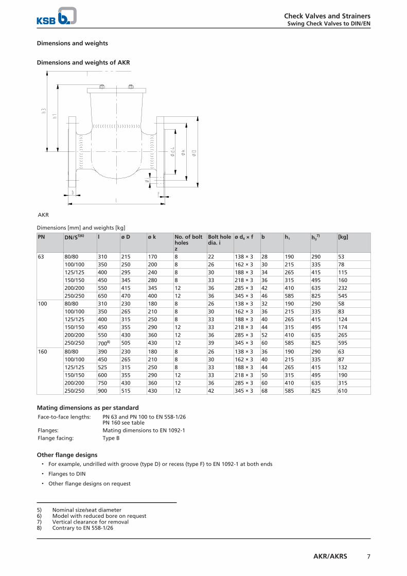
Dimensions and weights
Dimensions and weights of AKR
AKR
Dimensions [mm] and weights [kg]
PN DN/S5)6) l ø D ø k No. of boltholesz
Bolt holedia. i
ø d4 × f b h1 h37) [kg]
63 80/80 310 215 170 8 22 138 × 3 28 190 290 53100/100 350 250 200 8 26 162 × 3 30 215 335 78125/125 400 295 240 8 30 188 × 3 34 265 415 115150/150 450 345 280 8 33 218 × 3 36 315 495 160200/200 550 415 345 12 36 285 × 3 42 410 635 232250/250 650 470 400 12 36 345 × 3 46 585 825 545
100 80/80 310 230 180 8 26 138 × 3 32 190 290 58100/100 350 265 210 8 30 162 × 3 36 215 335 83125/125 400 315 250 8 33 188 × 3 40 265 415 124150/150 450 355 290 12 33 218 × 3 44 315 495 174200/200 550 430 360 12 36 285 × 3 52 410 635 265250/250 7008) 505 430 12 39 345 × 3 60 585 825 595
160 80/80 390 230 180 8 26 138 × 3 36 190 290 63100/100 450 265 210 8 30 162 × 3 40 215 335 87125/125 525 315 250 8 33 188 × 3 44 265 415 132150/150 600 355 290 12 33 218 × 3 50 315 495 190200/200 750 430 360 12 36 285 × 3 60 410 635 315250/250 900 515 430 12 42 345 × 3 68 585 825 610
Mating dimensions as per standardFace-to-face lengths: PN 63 and PN 100 to EN 558-1/26
PN 160 see tableFlanges: Mating dimensions to EN 1092-1Flange facing: Type B
Other flange designs▪ For example, undrilled with groove (type D) or recess (type F) to EN 1092-1 at both ends
▪ Flanges to DIN
▪ Other flange designs on request
5) Nominal size/seat diameter6) Model with reduced bore on request7) Vertical clearance for removal8) Contrary to EN 558-1/26

Check Valves and StrainersSwing Check Valves to DIN/EN
8 AKR/AKRS
Dimensions and weights of AKRS
AKRS Butt weld end
Dimensions [mm] and weights [kg]
PN DN/S9)10) l Butt weld ends,unmachined
Butt weld ends, machined h1 h311) [kg]
ø Amax. ø Bmin. ø d2 PN 63 PN 100 PN 160ø d3 Pipe
dimensionsø d3 Pipe
dimensionsø d3 Pipe
dimensions63/160 80/80 390 95 74 90 81 88,9 × 4,0 81 88,9 × 4,0 76,5 88,9 × 6,3 190 290 49
100/80 450 120 92 115 104 114,3 × 5,0 104 114,3 × 5,0 98,5 114,3 × 8,0 190 290 53100/100 450 120 92 115 104 114,3 × 5,0 104 114,3 × 5,0 98,5 114,3 × 8,0 215 335 70125/100 525 145 105 141 130,5 139,7 × 4,5 127 139,7 × 6,3 120,5 139,7 × 10,0 215 335 83125/125 525 145 115 141 130,5 139,7 × 4,5 127 139,7 × 6,3 120,5 139,7 × 10,0 265 415 103150/125 600 175 138 170 156,5 168,3 × 5,6 154 168,3 × 7,1 144,5 168,3 × 12,5 265 415 108150/150 600 175 138 170 156,5 168,3 × 5,6 154 168,3 × 7,1 144,5 168,3 × 12,5 315 495 140175/150 675 195 160 195 180,5 193,7 × 6,3 176,5 193,7 × 8,8 167 193,7 × 14,2 315 495 155200/150 750 225 180 222 204,5 219,1 × 7,1 199,5 219,1 × 10,0 189 219,1 × 16,0 315 495 166200/200 750 225 180 222 204,5 219,1 × 7,1 199,5 219,1 × 10,0 189 219,1 × 16,0 410 635 210250/200 900 280 225 276 255 273,0 × 8,8 248,5 273,0 × 12,5 231,5 273,0 × 22,2 410 635 250250/250 900 280 225 276 255 273,0 × 8,8 248,5 273,0 × 12,5 231,5 273,0 × 22,2 585 825 520300/250 1050 330 260 325 301 323,9 × 11,0 295,5 323,9 × 14,2 276,5 323,9 × 25,0 585 825 560
Mating dimensions as per standardFace-to-face lengths: EN 12982/26Butt weld ends: see tableWeld grooves: DIN EN ISO 9692-1 (1.3 + 1.5)
Different designs of butt weld ends and weld groove forms are possible, but only within the dimensions Amax. and Bmin..
Butt weld ends to EN 12627 are possible.
9) Nominal size/seat diameter10) Model with reduced bore on request11) Vertical clearance for removal


KSB SE & Co. KGaABahnhofplatz 1 • 91257 Pegnitz (Germany)Tel. +49 9241 71-0www.ksb.com
7373
.1/1
4-EN
17/0
1/20
18