AKM Magnetic Sensors - · PDF fileGMW Associates 650-802-8292 AKM Magnetic Sensors...
52
GMW Associates www.gmw.com 650-802-8292 AKM Magnetic Sensors Engineering Development Kits Demonstration Modules Application Case Studies AKM Semiconductor Inc www.akm.com Lou Law May 2011
Transcript of AKM Magnetic Sensors - · PDF fileGMW Associates 650-802-8292 AKM Magnetic Sensors...

GMW Associates www.gmw.com 650-802-8292
AKM Magnetic SensorsEngineering Development KitsDemonstration ModulesApplication Case Studies
AKM Semiconductor Inc
www.akm.com
Lou LawMay 2011


GMW Associates www.gmw.com 650-802-8292
AKM Engineering Development Kits and Product Support Documents
1 - AKM Hall Element KITs
AN_161KITs
AN_160KIT Universal Hall Interface Amplifier
2 - Gapped Core Current Sensor KITs using the AKM EQ-73XL Series Linear ICs
AN_130KIT EQ-730L
AN_131KIT EQ-731L
AN_135KIT EQ-733L
AN_136KIT EQ-733L
3 - CQ-121/131 Series Current Sensors KITS
AN_165KIT4 - CQ-20XX Series Current Sensors KITS
AN_170KIT5 - EM3242 Non-Contact Angle Sensor IC KITs
AN_133KIT
Reference Design RD101-EM3242
AN_134KIT
Reference Design RD102-EM3242
6 - Case Studies of Application using the AKM sensors
AKMCS-001 Non Contact Remote ON-OFF
AKMCS-002 Flow Meter using EM3242 Angle Sensor
AKMCS-003- Flow Meter using AKM Encoder IC’s
AKMCS-004 Accurate Position Sensing using AKM Hall Switches
7 - Demonstrators
AK8775/6 Encoder ICs

GMW Associates www.gmw.com 650-802-8292
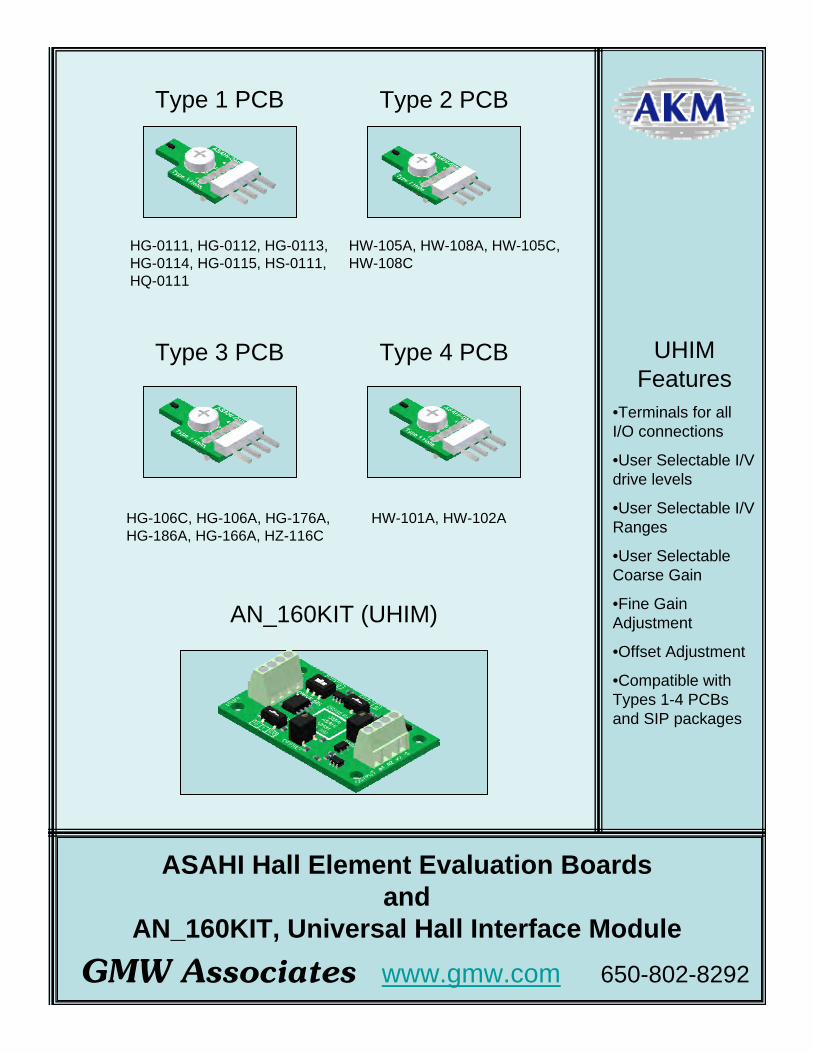
UHIM Features
•Terminals for all I/O connections
•User Selectable I/V drive levels
•User Selectable I/V Ranges
•User Selectable Coarse Gain
•Fine Gain Adjustment
•Offset Adjustment
•Compatible with Types 1-4 PCBs and SIP packages
ASAHI Hall Element Evaluation Boards and
AN_160KIT, Universal Hall Interface Module
HG-0111, HG-0112, HG-0113, HG-0114, HG-0115, HS-0111, HQ-0111
HW-105A, HW-108A, HW-105C, HW-108C
HG-106C, HG-106A, HG-176A, HG-186A, HG-166A, HZ-116C
HW-101A, HW-102A
Type 1 PCB
AN_160KIT (UHIM)
Type 2 PCB
Type 4 PCBType 3 PCB

Asahi Hall Element Test Kits - AN_161KIT Series
Revision Date: Feb 17,2011
GMW Associates: 955 Industrial Road, San Carlos, CA 94070, USA. www.gmw.com. +1 (650) 802-8292
1
DESCRIPTION
The AN_161KIT series of kits are PCB assemblies which provide an easy means to evaluate the Asahi Hall elements for magnetic fi eld, electric current or position sensing applications. These kits can be used independently by themselves or with the GMW AN_160KIT, Universal Hall Interface Module (UHIM). There are two basic connection schemes depending on the kit part number as shown below. See the AN_160KIT specifi cation sheet for details on the use of these kits with the UHIM.
AN_161KIT Series AN_162KIT Extension Cable(Required)
Connection Scheme
Confi guration for HG-0111, HG-0112, HG-0113, HG-0114, HG-0115, HG-106C, HG-106A, HG-166A, HG-176A, HG-186A
OR
Confi guration for HW-0105A, HW-0105C, HW-101A, HW-108A, HW-108C, HQ-0111, HS-0111
AN_162KIT Extension Cable (Optional)
AN_161KIT Series AN_161KIT Series
AN_160KIT
AN_161KIT Series
AN_162KIT Extension cable
AN_160KIT(UHIM)
AN_160KIT

Universal Hall Interface Module - AN_160KIT
Revision Date: Feb 17, 2011
GMW Associates: 955 Industrial Road, San Carlos, CA 94070, USA. www.gmw.com. +1 (650) 802-8292
1
DESCRIPTIONThe AN_160KIT is a Universal Hall Interface Module (UHIM) which provides an easy means to evaluate the Asahi Hall elements for magnetic fi eld, electric current or position sensing applications. The UHIM consists of a differential amplifi er, a voltage drive circuit for Hall elements requiring a voltage drive, a current drive circuit for Hall elements requiring current drive, and two analog output circuits to provide the standard 2.5V+/- 2.5V signal and a 1.5V+/- 1.5V signal for 0-3V input level A/D circuits. The kit provides selector switches to confi gure the UHIM to optimize the parameters for the various Asahi Hall elements and both a gain adjustment potentiometer and an offset adjustment potentiometer. The UHIM will interface with GWM’s Asahi element test PCB kits ( AN_161 series) and the SIP element packages
Fig 1. AN_160KIT Outline
Features: Terminal strips for all input/output connections User selectable current drive or voltage drive User selectable current or voltage drive ranges (10/1/5) mA or volts User selectable coarse gain ranges (1-10,10-100,100-1000) Fine Gain adjustment (1-10X) Offset adjustment Two Analog outputs ( 2.5+/-2.5V and 1.5V+/- 1.5V for 0-3V ADCs) Compatible with all Asahi/GMW Element test PCB KITS and SIP devices
AN_160KIT

Universal Hall Interface Module - AN_160KIT
Revision Date: Feb 17, 2011
GMW Associates: 955 Industrial Road, San Carlos, CA 94070, USA. www.gmw.com. +1 (650) 802-8292
2
Absolute Maximum RatingsSymbol Parameter Min. Typ. Max. Unit RemarksTSTG Storage Temperature -40 100 °CTA Ambient Temperature -10 85 °C With power applied
VDD Supply Voltage -0.5 +16.0 V
Recommended Operating ConditionsSymbol Parameter Min. Typ. Max. Unit Remarks
VDD Supply Voltage 5.5 5.5 16 V
A1 Analog Output 1 0.05 2.5 4.95 V
A2 Analog Output 2 0.05 1.5 2.95 V For 0-3 V A/D’s
SPECIFICATIONS
UHIM Confi guration
Hall Elements Element Kit Type Hall Element Kit P/N
(Ordered separately)
Extension Cable
Drive Select Drive Range (V) or (mA)
Coarse Gain Range
I (current)
V (voltage)
10 1 5 10 1 100
HG-0111, HG-0112 1 AN_161-xx-xxxx (1) Required X X X X X
HG-0114, HG-0115 1 AN_161-xx-xxxx (1) Required X X X X X
HS-0111 1 AN_161-xx-xxxx (1) Optional X X X X X
HG-0113 1 AN_161-xx-xxxx (1) Required X X X X X
HQ-0111 1 AN_161-xx-xxxx (1) Optional X X X X X
HW-105A, HW-108A, HW-105C, HW-108C 2 AN_161-xx-xxxx (1) Optional X X X X X
HG-106C, HG-106A 3 AN_161-xx-xxxx (1) Required X X X X X
HG-176A, HG-186A 3 AN_161-xx-xxxx (1) Required X X X X X
HG-166A 3 AN_161-xx-xxxx (1) Required X X X X X
HW-101A 4 AN_161-xx-xxxx (1) Optional X X X X X
HW-300B, HW-302B, HW-322B N/A SIP ( no kit required ) Optional X X X X X
HG-302C, HG-302A N/A SIP ( no kit required ) Optional X X X X X
Table 2. Asahi Hall Element Test Kit Selection and UHIM Confi guration table
Note: 1) Example: For a kit with the HG-0111 device the Hall element kit number would be AN_161-HG-0111

Universal Hall Interface Module - AN_160KIT
Revision Date: Feb 17, 2011
GMW Associates: 955 Industrial Road, San Carlos, CA 94070, USA. www.gmw.com. +1 (650) 802-8292
3
Fig. 2 Schematic, AN_160KIT
Power Input 5.5V-16V
Analog Output 2.5+/-2.5V
Hall Element Input or AN_161KITConnection
Analog Output 1.5+/-1.5V
Common
Analog Outputs Offset voltageadjustment- 11 turn potentiometer
Analog Output Fine Gain adjustment 11 turn potentiometer
Analog Outputs coarse Gain Range selection switch - 10X, 1X, 100X
Current Drive or Voltage Drive Select switch
Drive Range Select switch- When I/V Sel Switch is in I, range is 10mA,1mA or 5mA . When I/V Sel switch is in V, range is 10V, 1V or 5V
Fig. 3 - AN_160KIT Controls and Interconnect Layout

Universal Hall Interface Module - AN_160KIT
Revision Date: Feb 17, 2011
GMW Associates: 955 Industrial Road, San Carlos, CA 94070, USA. www.gmw.com. +1 (650) 802-8292
4
Application Notes: Connect the Hall element kit (AN_161-xx-xxx) or SIP Hall element to the AN_160KIT as shown in the above Figures ( 4 thru 7). Confi gure the AN_160KIT Module “Drive Sel” and “Drive Range” for the device being tested per the criteria shown in Table 2 Apply power ( 5.5V to 16VDC) to the terminals shown in Figure 3 Monitor the output (s) shown in Fig 3 with respect to common Set the “GAIN RANGE” switch, and adjust the “GAIN” and “OFFSET” potentiometers as needed
Fig 4 AN_160KIT UHIM with direct connection to the AN_161 Hall Element Kit
Fig 5 AN_160KIT UHIM with direct Hall Element SIP package connection
Fig 6 AN_160KIT UHIM with direct connection to the AN_161 Hall Element Kit
via AN_162KIT extension cable
Fig 7 AN_162KIT Extension Cable for AN_160KIT and AN_161 Hall Element Series Kit
AN_161 Series Kits
AN_160KIT
SIP PackageHall elements
AN_161 Series Kits
AN_160KIT

GMW Associates www.gmw.com 650-802-8292
Features•Low Noise-Wide Dynamic Range
•3 to 5.5V Operation
•4 Sensitivity ranges (20,40,65,130 mV/mT)
•SIP and SMD Packages
•Fast response time<2.5us
•DC to 100kHz
Gapped Core Current Sensors Kits using Asahi Low Noise Linear Hall Effect Sensor IC
Kolektor
(P/N T22G-10-06-04-1.25)
(P/N T22G-22-14-7-1.25)
Kolektor
(P/N T22G-10-06-04-1.25)
Kolektor
(P/N T22G-14-09-05-1.25)
AN_135KIT -40Arms
GMW
AN_136KIT -80Arms
GMW
AN_130KIT -12Arms
GMW
AN_131KIT -25Arms
GMW

AN_130KIT - Asahi EQ-730L Hall SensorGapped Core, Open Loop, Current Sensor Application
Revision Date: Feb 17, 2011
GMW Associates: 955 Industrial Road, San Carlos, CA 94070, USA. www.gmw.com. +1 (650) 802-8292
1
General DescriptionThe AN_130KIT provides an easy method of evaluating the Asahi EQ-730L
Linear Hall sensor IC in a “gapped core” current sensor application. The AN_130KIT includes the Asahi EQ-730L linear IC mounted in the nominal 1.25mm wide gap cut into a 10mm x 6 mm x 4mm Ferrite core. This confi guration produces a nominal output sensitivity of 120mV/A. The full scale current range is 12Arms or 17A peak. The kit includes a +5V regulator, however the circuit will work down to 2.7VDC. With the input voltage below 5V, the Hall IC supply is no longer regulated and the sensitivity, supply current and full scale output range will reduce by an amount directly proportional to the supply voltage. For example; at 3V, the sensitivity is 3/5 of 120mV/A will be equal to 73mV/A
The Asahi EQ-730L has a very fast response time, < 5uS, thereby making if very useful for over current applications. The Asahi EQ-730L broadband output noise characteristic is low, < 5mVpp, to give an operating range of about 2000mV/2.5mV or about 800:1.
Included in the kit is a mating connector
Features Measures AC or DC currents in wires up to 14AWG Nominal Sensitivity: 120 ±35 mV/A for 5V Supply and 73 ±22 mV/A for 3V Supply (EQ-730L Magnetic Sensitivity of 130 ±30 mV/mT) Nominal Quiescent Output Voltage: 2.5V+/- 0.20V @ Iprimary = 0A Fast response time: <5uS Wide bandwidth: DC to 300kHz (-3dB) Low noise:< 5mVpp Large Dynamic range > 800:1 Full scale output linear of 2.5V+/- 2.0V (With input supply voltage of 5.0 to 15VDC) Supply current: ≈ 8mA Supply voltage range of 2.7V to 15V (Below 5.0V, the voltage to the EQ-730L is unregulated) Galvanic isolation between primary conductor and sensor Interface Connector - 4 Pin 0.100” centers (Mating connector included) Bi-directional sensing Regulated Voltage Output (+5V) Pin (available for external use- up to 20mA)
AN_130KIT with mating connector
Mating Connector
Current Directionfor Positive Output
Primary Current
AN_130KIT Electrical Block Diagram
Primary CurrentCOM
Reg V Out
A1 Out
2.7-15V5VReg
5.6V
EQ-730L
References:Hall IC Specifi cation EQ-730LFerrite Core Specifi cation T 22G 10 06 04-02
0-12ArmsCurrent Range
AN-130KIT Outline Drawing (all dimensions in mm
COM
Reg V Out
A1 Out
2.7-15V

AN_130KIT - Asahi EQ-730L Hall SensorGapped Core, Open Loop, Current Sensor Application
Revision Date: Feb 17, 2011
GMW Associates: 955 Industrial Road, San Carlos, CA 94070, USA. www.gmw.com. +1 (650) 802-8292
2
Schematic, AN_130KIT
Parts List, AN_130KIT

AN_131KIT - Asahi EQ-731L Hall SensorGapped Core, Open Loop, Current Sensor Application
Revision Date: Feb 17, 2011
GMW Associates: 955 Industrial Road, San Carlos, CA 94070, USA. www.gmw.com. +1 (650) 802-8292
1
General DescriptionThe AN_131KIT provides an easy method of evaluating the Asahi EQ-731L
Linear Hall sensor IC in a “gapped core” current sensor application. The AN_131KIT includes the Asahi EQ-731L linear IC mounted in the nominal 1.25mm wide gap cut into a 10mm x 6 mm x 4mm Ferrite core. This confi guration produces a nominal output sensitivity of 60mV/A. The full scale current range is 25Arms or 35A peak. The kit includes a +5V regulator, however the circuit will work down to 2.7VDC. With the input voltage below 5V, the Hall IC supply is no longer regulated and the sensitivity, supply current and full scale output range will reduce by an amount directly proportional to the supply voltage. For exam-ple; at 3V, the sensitivity is 3/5 of 60mV/A will be equal to 36mV/A
The Asahi EQ-731L has a very fast response time, < 5uS, thereby making if very useful for over current applications. The Asahi EQ-731L broadband out-put noise characteristic is low, < 5mVpp, to give an operating range of about 2000mV/2.5mV or about 800:1.
Included in the kit is a mating connector
Features Measures AC or DC currents in wires up to 12AWG Nominal Sensitivity: 63 ±20 mV/A for 5V Supply and 36 ±12 mV/A for 3V Supply (EQ-731L Magnetic Sensitivity of 65 ±15 mV/mT Nominal Quiescent Output Voltage: 2.5V+/- 0.15V @ Iprimary = 0A Fast response time: <5uS Wide bandwidth: DC to 300kHz (-3dB) Low noise:< 5mVpp Large Dynamic range > 800:1 Full scale output linear of 2.5V+/- 2.0V (With input supply voltage of 5.0 to 15VDC) Supply current: ≈ 8mA Supply voltage range of 2.7V to 15V (Below 5.0V, the voltage to the EQ-731L is unregulated) Galvanic isolation between primary conductor and sensor Interface Connector - 4 Pin 0.100” centers (Mating connector included) Bi-directional sensing Regulated Voltage Output (+5V) Pin (available for external use- up to 20mA)
AN_131KIT with mating connector
Mating Connector
Current Directionfor Positive Output
Primary Current
AN_131KIT Electrical Block Diagram
Primary CurrentCOM
Reg V Out
A1 Out
2.7-15V5VReg
5.6V
EQ-731L
References:Hall IC Specifi cation EQ-731LFerrite Core Specifi cation T 22G 10 06 04-02
0-25ArmsCurrent Range
AN-131KIT Outline Drawing (all dimensions in mm
COM
Reg V Out
A1 Out
2.7-15V
3.55

AN_131KIT - Asahi EQ-731L Hall SensorGapped Core, Open Loop, Current Sensor Application
Revision Date: Feb 17, 2011
GMW Associates: 955 Industrial Road, San Carlos, CA 94070, USA. www.gmw.com. +1 (650) 802-8292
2
Schematic, AN_131KIT
Parts List, AN_131KIT
AN_135KIT - Asahi EQ-732L Hall SensorGapped Core, Open Loop, Current Sensor Application
Revision Date: Feb 17,2011
GMW Associates: 955 Industrial Road, San Carlos, CA 94070, USA. www.gmw.com. +1 (650) 802-8292
1
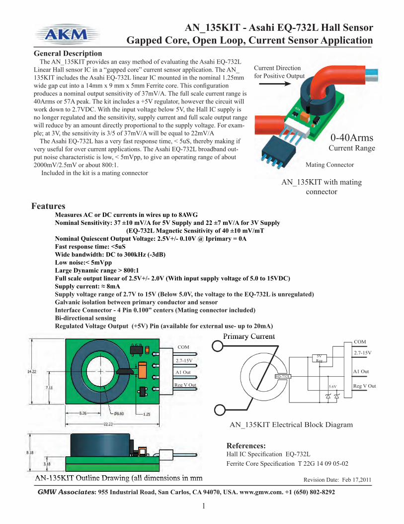
General DescriptionThe AN_135KIT provides an easy method of evaluating the Asahi EQ-732L
Linear Hall sensor IC in a “gapped core” current sensor application. The AN_135KIT includes the Asahi EQ-732L linear IC mounted in the nominal 1.25mm wide gap cut into a 14mm x 9 mm x 5mm Ferrite core. This confi guration produces a nominal output sensitivity of 37mV/A. The full scale current range is 40Arms or 57A peak. The kit includes a +5V regulator, however the circuit will work down to 2.7VDC. With the input voltage below 5V, the Hall IC supply is no longer regulated and the sensitivity, supply current and full scale output range will reduce by an amount directly proportional to the supply voltage. For exam-ple; at 3V, the sensitivity is 3/5 of 37mV/A will be equal to 22mV/A
The Asahi EQ-732L has a very fast response time, < 5uS, thereby making if very useful for over current applications. The Asahi EQ-732L broadband out-put noise characteristic is low, < 5mVpp, to give an operating range of about 2000mV/2.5mV or about 800:1.
Included in the kit is a mating connector
Features Measures AC or DC currents in wires up to 8AWG Nominal Sensitivity: 37 ±10 mV/A for 5V Supply and 22 ±7 mV/A for 3V Supply (EQ-732L Magnetic Sensitivity of 40 ±10 mV/mT Nominal Quiescent Output Voltage: 2.5V+/- 0.10V @ Iprimary = 0A Fast response time: <5uS Wide bandwidth: DC to 300kHz (-3dB) Low noise:< 5mVpp Large Dynamic range > 800:1 Full scale output linear of 2.5V+/- 2.0V (With input supply voltage of 5.0 to 15VDC) Supply current: ≈ 8mA Supply voltage range of 2.7V to 15V (Below 5.0V, the voltage to the EQ-732L is unregulated) Galvanic isolation between primary conductor and sensor Interface Connector - 4 Pin 0.100” centers (Mating connector included) Bi-directional sensing Regulated Voltage Output (+5V) Pin (available for external use- up to 20mA)
AN_135KIT with mating connector
AN_135KIT with mating
Mating Connector
Current Directionfor Positive Output
Primary Current
AN_135KIT Electrical Block Diagram
Primary CurrentCOM
Reg V Out
A1 Out
2.7-15V5VReg
5.6V
EQ-732L
References:Hall IC Specifi cation EQ-732LFerrite Core Specifi cation T 22G 14 09 05-02
0-40ArmsCurrent Range
AN-135KIT Outline Drawing (all dimensions in mmAN-135KIT Outline Drawing (all dimensions in mm
COM
Reg V Out
A1 Out
2.7-15V

AN_135KIT - Asahi EQ-732L Hall SensorGapped Core, Open Loop, Current Sensor Application
Revision Date: Feb 17,2011
GMW Associates: 955 Industrial Road, San Carlos, CA 94070, USA. www.gmw.com. +1 (650) 802-8292
2
Schematic, AN_135KIT
Parts List, AN_135KIT
AN_136KIT - Asahi EQ-733L Hall SensorGapped Core, Open Loop, Current Sensor Application
Revision Date: 27 Oct 2009
GMW Associates: 955 Industrial Road, San Carlos, CA 94070, USA. www.gmw.com. +1 (650) 802-8292
1
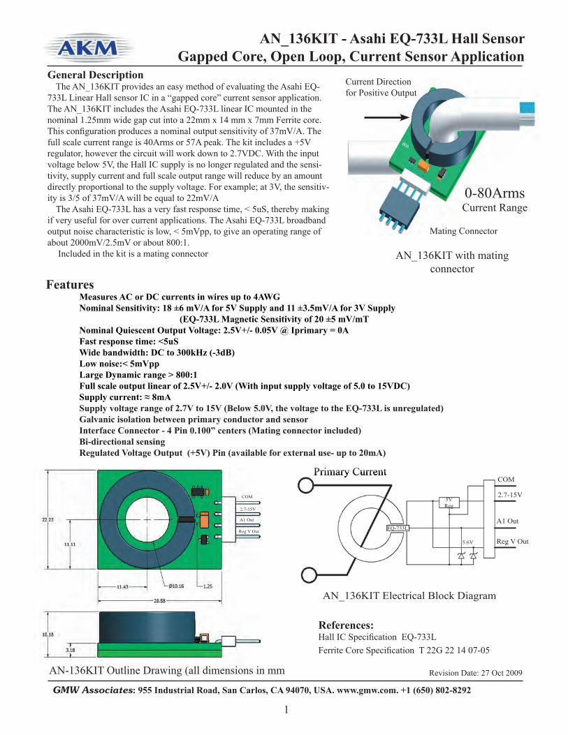
General DescriptionThe AN_136KIT provides an easy method of evaluating the Asahi EQ-
733L Linear Hall sensor IC in a “gapped core” current sensor application. The AN_136KIT includes the Asahi EQ-733L linear IC mounted in the nominal 1.25mm wide gap cut into a 22mm x 14 mm x 7mm Ferrite core. This confi guration produces a nominal output sensitivity of 37mV/A. The full scale current range is 40Arms or 57A peak. The kit includes a +5V regulator, however the circuit will work down to 2.7VDC. With the input voltage below 5V, the Hall IC supply is no longer regulated and the sensi-tivity, supply current and full scale output range will reduce by an amount directly proportional to the supply voltage. For example; at 3V, the sensitiv-ity is 3/5 of 37mV/A will be equal to 22mV/A
The Asahi EQ-733L has a very fast response time, < 5uS, thereby making if very useful for over current applications. The Asahi EQ-733L broadband output noise characteristic is low, < 5mVpp, to give an operating range of about 2000mV/2.5mV or about 800:1.
Included in the kit is a mating connector
Features Measures AC or DC currents in wires up to 4AWG Nominal Sensitivity: 18 ±6 mV/A for 5V Supply and 11 ±3.5mV/A for 3V Supply (EQ-733L Magnetic Sensitivity of 20 ±5 mV/mT Nominal Quiescent Output Voltage: 2.5V+/- 0.05V @ Iprimary = 0A Fast response time: <5uS Wide bandwidth: DC to 300kHz (-3dB) Low noise:< 5mVpp Large Dynamic range > 800:1 Full scale output linear of 2.5V+/- 2.0V (With input supply voltage of 5.0 to 15VDC) Supply current: ≈ 8mA Supply voltage range of 2.7V to 15V (Below 5.0V, the voltage to the EQ-733L is unregulated) Galvanic isolation between primary conductor and sensor Interface Connector - 4 Pin 0.100” centers (Mating connector included) Bi-directional sensing Regulated Voltage Output (+5V) Pin (available for external use- up to 20mA)
AN_136KIT with mating connector
Mating Connector
Current Directionfor Positive Output
Primary Current
AN_136KIT Electrical Block Diagram
Primary CurrentCOM
Reg V Out
A1 Out
2.7-15V5VReg
5.6V
EQ-733L
References:Hall IC Specifi cation EQ-733LFerrite Core Specifi cation T 22G 22 14 07-05
0-80ArmsCurrent Range
AN-136KIT Outline Drawing (all dimensions in mm
COM
Reg V Out
A1 Out
2.7-15V

AN_136KIT - Asahi EQ-733L Hall SensorGapped Core, Open Loop, Current Sensor Application
Revision Date: 27 Oct 2009
GMW Associates: 955 Industrial Road, San Carlos, CA 94070, USA. www.gmw.com. +1 (650) 802-8292
2
Schematic, AN_136KIT
Parts List, AN_1356KIT


GMW Associates www.gmw.com 650-802-8292
Features•Very Low Noise
•High Isolation Voltage
•DC AC Operation
•Large Dynamic Range
•3 to 5.5V Operation
•DC to 100kHz
AN_165KIT 25A
ASAHI Current Sensor and Engineering Development Kits
AN_165KIT 50A
CQ-121E 25A
CQ-121E 50A
Components Engineering Kits

AN_165KIT-25A/50A - Asahi Current SensorEngineering Evaluation Kits
Revision Date: Feb 17 2011
GMW Associates: 955 Industrial Road, San Carlos, CA 94070, USA. www.gmw.com. +1 (650) 802-8292
1
General DescriptionThe AN_165KIT-25A and AN_165KIT-50A engineering development kits
provide an easy method of evaluating the Asahi CQ-121E and CQ-131E linear Hall current sensors. The AN_165KIT-25A demonstrates the Asahi CQ-121E sensor and has a current range of +/-25A. The AN_165KIT-50A demonstrates CQ-131E and has a range of +/-50A. The CQ Series incorporates the Asahi EQ-711L Linear Hall IC and a custom ferrite core.
Included in the kit is a mating connector
AN_165KIT-25A with mating connector
KIT Part NumbersAN_165KIT-25AAN_165KIT-50A
AN-165KIT Outline Drawing (all dimensions in mm)
Features Small-sized open loop current transducer using Linear Hall Effect IC Galvanic isolation between the primary conductor and the Hall Effect IC. Sensitivity range: 63+/- 8mV/A Analog output voltage range: 1/2Vcc +/- 95% Vcc Offset voltage: 1/2Vcc +/- 6% Supply voltage range: 3-5.5V Ratiometric analog output Quick response: Typ. 3μs Supply current: Typ.9mA Operating Temperature Range:-30 to +80
Current Out
Current In
NCVout-A1Power 3-5.5VCommon
Mating Connector
0+/-25ACurrent Range
CQ-121E
References:Asahi Sensor Specifi cation CQ-121E/CQ-131EAsahi Linear Hall Specifi cation EQ-711L
CQ-121E CQ-131E

GMW Associates www.gmw.com 650-802-8292
Features• 2,5V+/-2.4V signal
• Ratiometric output
• DC & AC operation
• Very low noise<2mVrms
• Large dynamic range: 1000:1
• High isolation voltage
• Single 5.0V supply
• DC to 400kHz
• 1uS response time
• +/-2 % accuracyAN_170KITFor the CQ-2092
AKM Current Sensor and Engineering Development Kits
Components Engineering Kits
CQ-2092 +/-21A, 20Arms
CQ-2093 +/-35A, 20Arms
CQ-2063 +/-35A, 50Arms
CQ-2094 +/-54A, 50Arms
CQ-2063 +/-85A, 50Arms
CQ-2094 +/-130A, 50Arms

AN_170KIT, AKM CQ-2092 Current SensorEngineering Evaluation Kit
Revision Date: May 9th, 2011
GMW Associates: 955 Industrial Road, San Carlos, CA 94070, USA. www.gmw.com. +1 (650) 802-8292
1
General Description
The AN_170KIT engineering development kit provides an easy method of evaluating the AKM CQ-2092 linear Hall current sensor. The AN_170KIT demonstrates the AKM CQ-2092 sensor and has a current range of +/-20A. The CQ-2092 current sensor incorporates the AKM EQ-950L factory programmed Linear Hall IC and a custom ferrite core. The kit in-cludes a 5V regulator for the CQ-2092 and will operate with an input Vcc voltage of 5V to 24Vdc
KIT Part NumberAN_170KIT
Features Small-sized open loop current transducer using a factory programmed Linear Hall Effect IC
Galvanic isolation between the primary conductor and the Hall Effect IC. >2.5kV Sensitivity range: 100+/- 2mV/A (+/-2%) Analog output voltage range: 2.5V +/- 2.4V Offset voltage: 2.50V +/- 110mV Kit supply voltage range: 5V to 24Vdc Supply current: Typ. <9mA Large BW: dc to 400kHz (-3db) Fast response: Typ. 1μs delay Ratiometric analog output Operating temperature range:-40 to +90 °C Very low output noise: <2.5mVrms
Large Dynamic Range 1000:1
References:AKM Sensor Specifi cation: CQ-2092 Linear Current Sensor
AN_170KIT with mating connector and pigtail
CQ-2092 SMT Current sensor
AN_170KIT Outline Drawing (all dimensions in mm)
Analog OutputReg +5V OutputCommon+Vcc
Mating 4 socket connector with 350mm pigtail-Molex WM2002
AKM CQ-2092
Current In (RED)
Current Out (BLK)
4 pin connector -Molex WM4302

AN_170KIT, AKM CQ-2092 Current SensorEngineering Evaluation Kit
Revision Date: May 9th, 2011
GMW Associates: 955 Industrial Road, San Carlos, CA 94070, USA. www.gmw.com. +1 (650) 802-8292
2
AN_170KIT
AKMCQ-2092
Current IN
Current OUT
Vcc 5 to 24Vdc@9mA
COM
+5V Out
Analog Vout
Schematic, AN_170KIT
Molex WM2002Molex WM4302


GMW Associates www.gmw.com 650-802-8292
EM-3242 Features
•Non–Contact Angle Sensing
•3 to 5.5V Operation
•360 Degree Range
•Very small 6 Pin SMD
•High Speed Operation
•Large Air-Gap
Reference Design RD101-EM-3242
ASAHI EM-3242 360 Degree Non-Contact Angle Sensing IC with Pre-Engineered Reference Designs and Development Kits
With “Out of Range” Detector Disabled
Reference Design RD102-EM-3242With “Out of Range” Detector Enabled
AN_134KIT
AN_133KIT

Revision Date: 03 May 2007 AN_132KIT
955 Industrial Road, San Carlos, CA 94070 Tel: (650) 802-8292 Fax: (650) 802-8298E-mail: [email protected] Web Site: www.gmw.comGMW
1
AN_133KIT
GENERAL DESCRIPTIONThe AN_133KIT consists of a EM3242 angle sensor mounted on a small 0.25” square PCB with a 2 inch fl at cable. Also included in kit are two SmCo24 magnets compatible with the angle sensor, a 0.25” dia. magnet and a 0.25” square magnet. The sensor works well with smaller magnets but with less air gap. This kit eliminates the need to design a PCB for testing which makes it convenient to evaluate the EM3242 for compatibility to the user’s applications. See EM3242 specifi cation for details.
ASAHI KASEI EMD - EM3242 Non-Contact Angle Sensor Engineer Evaluation Kit
FEATURES of the EM3242Non-Contact Angle Sensor• Non-Contact Angle Sensing• Senses magnetic fi eld orientation of a small permanent magnet• Small Size 3.6 x 3.0 x 0.8 mm - 6pin SOIC• Resolution of up to 10 bits (0.35 deg)• Non-linearity - 1%• Low Power -Typ. 10mA @3.0V• Sleep Mode - 1uA current draw• Linear ratio-metric analog output voltage proportional to 0-360deg• Single supply (2.7 to 5.25 V operating)• Only one external part required - 0.1uF Capacitor• Very High Speed > 8K RPM
Magnet Field Orientation
“0” Degrees Clockwise rotation increases the output voltage.
Outline Drawing
“0” Degrees Clockwise rotation increases the output
Outline Drawing
Air Gap range for standard RD and SQ magnets
Outline DrawingOutline Drawing
EM3242 Angle Sensor, Output vs Angle
Vcc = 3.0VNote: Output is proportional to Vcc
FEATURES of the EM3242Non-Contact Angle Sensor
Senses magnetic fi eld orientation of a small permanent magnet
• Linear ratio-metric analog output voltage proportional to 0-360deg
AN_133Kit Components
55C0126
55B0082
PCB Assy
(Optional)
Connection Diagram - AN_133KIT

AKM EM-3242 360 Deg Angle Position Ref Design without “In Range” Detection RD101-EM3242
Revision Date: Feb 17. 2011
GMW Associates: 955 Industrial Road, San Carlos, CA 94070, USA. www.gmw.com. +1 (650) 802-8292
1
The RD101-EM3242 is a reference design for the AKM EM-3242 Non-Contact Angle Position Sensing IC. The EM-3242 senses the angle of magnetic fi eld compo-nent in the top plane of the device package. The EM-3242 provides an analog output voltage of 10% to 90% of the supply voltage for a mechanical angle range of 360 degrees of rotation. The EM-3242 has two operating modes. One with the “In Range” detector enabled and one with the “In Range” detector disabled. The “In Range” detec-tor includes internal circuitry which causes the output voltage to drop to 0V whenever the magnetic fi eld level at the EM-3242 is greater than 60mT or less than 10mT. This reference design illustrates the operating mode which has the “In-Range” detector disabled. Please note that the PDN (Power Down) function is also disabled in this mode. GMW offers a development kit that can be used to demostrate this reference design. The kit P/N is AN_133KIT RD102-EM3242 details the design for a angle sensor that has the “In Range” detector enabled and the PDN (Power Down) enabled.
EM-3242 on PCB with 0.250” dia.. X 0.150 thick SmCo24
magnet (55B0082).FEATURES 360 Degree Non-Contact Magnetic Angle Position Sensing Analog Output 10% to 90% of VDD Nonlinearity less than 3.5 deg at 3V Magnetic to EM-3242 separation of 0.120’ to 0.190” (55B0082 magnet) Tolerant of mechanical misalignment Expanded Magnet to IC separation with increased non-linearity
Only 1 external component required ( 0.1uF) Less than 10mA operating current Ratio-metric output Very small 6 pin IC package (3.6mm x 4.2mm). Circuitry fi ts on a 0.25” x 0.25” PCB. 10 Bit Resolution (0.36 deg)
Schematic Diagram
Reference DocumentsEM-3242 Specifi cation Sheet - July, 2008
55B0082 Spec Sheet (0.25”dia. x 0.15”T SmCo24 Magnet) 55B0081 Spec Sheet (0.15”dia. x 0.15”T SmCo24 Magnet) 55C0126 Spec Sheet (0.25”Sq. x 0.10”T SmCo24 Magnet) AN_133KIT- Eng Development Kit RD102-EM3242 Ref Design for Angle sensing with “In Range” Detector
Bill of Material IC-1 EM-3242 IC C1- 0.1uF Ceramic cap-0603 SMD +/-10% PCB FR-4, 0.8mm thick, 0.5 oz copper 55B0082 Cylindrical Magnet or 55B0081 Cylindrical Magnet or 55C0126 Square Magnet
Magnetic fl ux density (Magnetic Field) units of Gauss and Tesla
1G=100uT or 0.1mT 10G =1mT 100G =10mT
VSS (COM)

AKM EM-3242 360 Deg Angle Position Ref Design without “In Range” Detection RD101-EM3242
Revision Date: Feb 17. 2011
GMW Associates: 955 Industrial Road, San Carlos, CA 94070, USA. www.gmw.com. +1 (650) 802-8292
2
0°
270°
90°
180°
Air Gap Operating Range for the 55C0126 Square Magnet
Air Gap Operating Range for the 55B0081 Cylindrical Magnet
Air Gap Operating Range for the 55B0082 Cylindrical Magnet
PCB Artwork PCB Outline DiagramEM-3242 Solder PAD Recommendation
Magnet Orientation
Output increases as magnet is rotated CounterClockwise. See output curve, next page
Zero Degrees occurs when the South Pole of the magnet is in line with pin and 6 of the IC.
Air-Gap ranges to produce specifi ed linear ouput. See graph on page 4 for expanded ranges
N S
EM-3242 Package and location of sesning element
1-TSTB2-VSS3-PDN4-AOUT5- VDD6-TSTA
Sensing Element
N S
0.075” to 0.120”1.9mm to 3mm
N S
0.110” to 0.180”2.8mm to 4.6mm

AKM EM-3242 360 Deg Angle Position Ref Design without “In Range” Detection RD101-EM3242
Revision Date: Feb 17. 2011
GMW Associates: 955 Industrial Road, San Carlos, CA 94070, USA. www.gmw.com. +1 (650) 802-8292
3
AOUT vs POSITION OF SOUTH POLE OF MAGNET
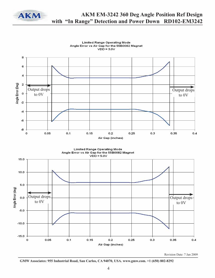
Non-Linearity Specifi cations.The EM-3242 is specifi ed to operate within +/-6 degrees of non-linearity when the supply is 3V over the magnetic fi eld range of 20mT to 40mT. With the ”In Range” detector disabled, as in this case, the sensor will continue to function normally over a wider range, but with an increased angle error. The following graphs show the relationship between the non-linearity range and the air gap between the magnet and sensor for the 55B0082 magnet.
360 to 0 Degree Transition When the Angle of rotation approaches the 360 degree position, the output will approach 90% of the supply voltage and then abruptly change to 10% of VDD and then start increasing again as the angle increases. This transition can be a wide as 0.5deg. If the position of the magnet is held steady at a point within the 0.5 deg. range, there is a possibility that the output will randomly switch between the 90% level and the 10% level. Both levels represent the same angle of 0 deg. If the output is fi ltered with a low pass fi lter, the average voltage output could be approximately 50% of VDD, thus creating an error in the reading. This can be avoided by not using a low pass fi lter. If a uP is used to sample the output, it can simply register a 10%VDD reading and a 90%VDD reading as the same angle (zero degrees).

AKM EM-3242 360 Deg Angle Position Ref Design without “In Range” Detection RD101-EM3242
Revision Date: Feb 17. 2011
GMW Associates: 955 Industrial Road, San Carlos, CA 94070, USA. www.gmw.com. +1 (650) 802-8292
4

Revision Date: 15 Dec 2009
955 Industrial Road, San Carlos, CA 94070 Tel: (650) 802-8292 Fax: (650) 802-8298E-mail: [email protected] Web Site: www.gmw.comGMW
1
AN_134KIT
GENERAL DESCRIPTIONThe AN_134KIT consists of a EM-3242 angle sensor mounted on a small 0.25” square PCB with a 6 inch fl at cable. Also included in kit are three SmCo24 magnets compatible with the angle sensor, a 0.25” dia. magnet, a 0.15” dia magnet and a 0.25” square magnet. The sensor works well with smaller magnets but with less air gap. The Sensor incorporates a “Out or Range “ detector circuit and will fault the output to zero volts when the magnet’s strength is either too weak or too strong. See RD102-EM3242 for details. This kit eliminates the need to design a PCB for testing which makes it convenient to evaluate the EM-3242 for compatibility to the user’s applications. See EM-3242 specifi cation for details.
ASAHI KASEI EMD - EM-3242 Non-Contact Angle Sensorwithout “In Range” Detection Engineering Development Kit
FEATURES of the EM-3242 Non-Contact Angle Sensor• Non-Contact Angle Sensing• Senses magnetic fi eld orientation of a small permanent magnet• Small Size 3.6 x 3.0 x 0.8 mm - 6 pin SOIC• Resolution of up to 10 bits (0.35 deg)• Non-linearity - 1% (at 3V)• Low Power -Typ. 9mA • Sleep Mode - 1uA current draw• Linear ratio-metric analog output voltage proportional to 0-360deg• Single supply (2.7 to 5.5V operating)• Only one external part required - 0.1uF Capacitor• Very High Speed > 8K RPM• “Out of Range” Detection
Outline DrawingOutline Drawing
Air Gap range for the 55B0082 standard magnets
EM-3242 Angle Sensor, Output vs Rotation Angle
Connection Diagram - AN_134KIT
without “In Range” Detection Engineering Development Kit
FEATURES of the EM-3242 Non-Contact Angle Sensor
Senses magnetic fi eld orientation of a small permanent magnet
• Linear ratio-metric analog output voltage proportional to 0-360deg
AN_134KIT Components
55C0126
55B0082
PCB Assy
(0.25” x 0.15”)
(0.25” x 0.25”)
Magnet Field Orientation
“0” Degrees Counter Clockwise rotation increases the output voltage.
N S
55B0081(0.150” x0.150”)
0.175 +/- 0.075”(4.45+/- 1.91mm)
the user’s applications. See EM-3242 specifi cation for details.
6.0”(152mm)
PDCOM+VddAOUT

AKM EM-3242 360 Deg Angle Position Ref Design with “In Range” Detection and Power Down RD102-EM3242
Revision Date: 7 Jan 2009
GMW Associates: 955 Industrial Road, San Carlos, CA 94070, USA. www.gmw.com. +1 (650) 802-8292
1
The RD102-EM3242 is a reference design for the AKM EM-3242 Non-Contact Angle Position Sensing IC. The EM-3242 senses the angle of magnetic fi eld component in the top plane of the device package. The EM-3242 provides an analog output voltage of 10% to 90% of the supply voltage for a mechanical angle range of 360 degrees of rotation. The EM-3242 has two operating modes. One with the “In Range” detector en-abled and one with the “In Range” detector disabled. The “In Range” detector includes internal circuitry which causes the output voltage to drop to 0V whenever the magnetic fi eld level at the EM-3242 is greater than 60mT or less than 10mT. This reference design illustrates the operating mode which has the “In-Range” detector enabled. Please note that the PDN (Power Down) function is also enabled in this mode. GMW offers an engineering development kit that can be used to evaluate this reference design. The P/N is AN_134KIT RD101-EM3242 details the design for a angle sensor that has the “In Range” detector enabled and the PDN (Power Down) enabled.
EM-3242 on PCB with 0.250” dia. X 0.150 thick
SmCo24 magnet (55B0081).FEATURES 360 Degree Non-Contact Magnetic Angle Position Sensing Analog Output 10% to 90% of VDD Nonlinearity less than 3.5 deg at 3V Magnetic to EM-3242 separation of 0.100’ to 0.250” Tolerant of mechanical misalignment Expanded Magnet to IC separation with increased non-linearity Out of Range Detection (Faults to 0V when Magnetic Field is >60mT or <10mT. Power Down (PDN) option reduces current draw to <10uA.
Only 1 external component required ( 0.1uF) Less than 10mA operating current Ratio-metric output Very small 6 pin IC package (3.6mm x 4.2mm). Circuitry fi ts on a 0.25” x 0.25” PCB. 10 Bit Resolution (0.36 deg) Fast update speed (40uS/update)
Schematic Diagram
Reference DocumentsEM-3242 Specifi cation Sheet - July, 2008
55B0082 Spec Sheet (0.25”dia. x 0.15”T SmCo24 Magnet) 55B0081 Spec Sheet (0.15”dia. x 0.15”T SmCo24 Magnet) 55C0126 Spec Sheet (0.25”Sq. x 0.10”T SmCo24 Magnet) AN_134KIT- Eng Development Kit RD101-EM3242 Ref Design for Angle sensing without “In Range” Detector
Bill of Material IC-1 EM-3242 IC C1- 0.1uF Ceramic cap-0603 SMD +/-10% PCB FR-4, 0.8mm thick, 0.5 oz copper 55B0082 Cylindrical Magnet or 55B0081 Cylindrical Magnet or 55C0126 Square Magnet
Magnetic fl ux density (Magnetic Field) units of Gauss and Tesla
1G=100uT or 0.1mT 10G =1mT 100G =10mT
Operating Note:Power Down (PDN) is enabled when PDN is tied to VSS (COM).Tie PDN to +VDD activate the sensor for normal operation
AOUT
+VDD
VSS (COM)
PDN(See Operating Note)

AKM EM-3242 360 Deg Angle Position Ref Design with “In Range” Detection and Power Down RD102-EM3242
Revision Date: 7 Jan 2009
GMW Associates: 955 Industrial Road, San Carlos, CA 94070, USA. www.gmw.com. +1 (650) 802-8292
2
0°
270°
90°
180°
Air Gap Operating Range for the 55C0126 Square Magnet
Air Gap Operating Range for the 55B0081 Cylindrical Magnet
Air Gap Operating Range for the 55B0082 Cylindrical Magnet
PCB Artwork PCB Outline DiagramEM-3242 Solder PAD Recommendation
Magnet Orientation
Output increases as magnet is rotated CounterClockwise. See output curve, next page
Zero Degrees occurs when the South Pole of the magnet is in line with pin and 6 of the IC.
Air-Gap ranges to produce specifi ed linear ouput. See graph on page 4 for expanded ranges
N S
N SN S
EM-3242 Package and location of sesning element
1-TSTB2-VSS3-PDN4-AOUT5- VDD6-TSTA
Sensing Element

AKM EM-3242 360 Deg Angle Position Ref Design with “In Range” Detection and Power Down RD102-EM3242
Revision Date: 7 Jan 2009
GMW Associates: 955 Industrial Road, San Carlos, CA 94070, USA. www.gmw.com. +1 (650) 802-8292
3
AOUT vs POSITION OF SOUTH POLE OF MAGNET
Non-Linearity Specifi cations.The EM-3242 is specifi ed to operate within +/-3.5 degrees of non-linearity when the supply is 3V and +/-6 degrees when the supply voltage is 5V over the magnetic fi eld range of 20mT to 50mT. With the ”In Range” detector enabled, as in this case, the sensor will continue operate normally until the magnetic fi eld strength at the sensor either exceeds 60mT or drops below 10mT. When these limits are exceeded, the output of the EM-3242 will drop to 0.2V or less. The following graphs show the relationship between the non-linearity range and the air gap between the magnet and sensor for the 55B0082 magnet.
360 to 0 Degree Transition When the Angle of rotation approaches the 360 degree position, the output will approach 90% of the supply voltage and then abruptly change to 10% of VDD and then start increasing again as the angle increases. This transition can be a wide as 0.5deg. If the position of the magnet is held steady at a point within the 0.5 deg. range, there is a possibility that the output will randomly switch between the 90% level and the 10% level. Both levels represent the same angle of 0 deg. If the output is fi ltered with a low pass fi lter, the average voltage output could be approximately 50% of VDD, thus creating an error in the reading. This can be avoided by not using a low pass fi lter. If a uP is used to sample the output, it can simply register a 10%VDD reading and a 90%VDD reading as the same angle (zero degrees).
AKM EM-3242 360 Deg Angle Position Ref Design with “In Range” Detection and Power Down RD102-EM3242
Revision Date: 7 Jan 2009
GMW Associates: 955 Industrial Road, San Carlos, CA 94070, USA. www.gmw.com. +1 (650) 802-8292
4
Output drops to 0V
Output drops to 0V
Output drops to 0V
Output drops to 0V
Output drops to 0V
Output drops to 0V


GMW Associates www.gmw.com 650-802-8292
Case Studies
AKMCS-001 Non Contact Remote ON-OFF
AKMCS-002 Flow Meter using EM3242 Angle Sensor
AKMCS-003- Flow Meter using AKM Encoder IC’s
AKMCS-004 Accurate Switching using AKM Hall devices

AKM Case Study: AKMCS 001Non-Contact power turn ON/OFF
Revision Date: 21 Jan 2011
1
955 Industrial Rd, San Carlos, CA 94070 Tel: (650) 802-8292 Fax: (650) 802-8298Email: [email protected] Web site: http:// www.gmw.com
GMW
Problem to be solved:
Customer needs a solution for turning power ON and OFF in a sealed container (In this case, a small battery operated gastrointestinal ingestible capsule). The capsule contains sensors and telemetry circuitry that is powered by a small battery.
The customer’s needs are the following: 1) Very low operating current draw 2) Operate at low battery voltages 3) Activated with a magnet 4) Needs to be latched ON or OFF with the external magnet 5) Small size
GMW recommended solution
GMW offered the customer a solution that would use the AKM Low Power Hall switch to activate the internal circuitry with a magnet. The Hall IC recommended was the AKM EM-1712 which has the following characteristics applicable to the issue. 1) Very low operating current <60uA. This will be well suited for battery operation 2) The operating voltage is 1.6V to 5.5V 3) The IC is a Hall switch which is activated by a magnetic field, in this case from a small magnet
4) The IC is a “Latching Hall” device whose output remains in the state that it was last activated to. A North pole of a magnet will switch the output to high and a South pole will latch the output to low. This allows the customer to turn the IC on (That is: Latch it ON) and then turn it off with an external magnet. Once the capsule is assembled and just prior to shipment, it is sealed and tested by momentarily switching the device ON and OFF. 5) The EM-1712 IC comes in a very small SMT package (2.1mm square). AKM has a smaller version, the EM-0712, which comes in a leadless SON package however in this case, the customer preferred the leaded SMT package.

AKM Case Study: AKMCS 001Non-Contact power turn ON/OFF
Revision Date: 21 Jan 2011
2
955 Industrial Rd, San Carlos, CA 94070 Tel: (650) 802-8292 Fax: (650) 802-8298Email: [email protected] Web site: http:// www.gmw.com
GMW
Below is a typical schematic of the AKM EM-1712 being used to turn power ON and OFF.Thsi circuit shows the AKM EM-1732 being used to turn a regulator circuit On and OFF . When the EM-1712 is in the OFF state ( South Pole toward the top of the IC), the EM-1712’s output is LOW, which disables the regulator. When the EM-1712 is activated and latch to the high state with a North pole facing the top of the IC, the regulator is turned on to activate the circuity in the capsule. Because the EM-1712 is a “Latching” Hall IC, it will remain in a given state until activated by a magnet with the opposite polarity.

AKM Case Study: AKMCS 001Non-Contact power turn ON/OFF
Revision Date: 21 Jan 2011
3
955 Industrial Rd, San Carlos, CA 94070 Tel: (650) 802-8292 Fax: (650) 802-8298Email: [email protected] Web site: http:// www.gmw.com
GMW
Below are the technical details of the switch operation. The magnet North pole of a magnet facing the bottom of the IC will cause the output to switch “Low”. A North pole of a magnet facing the top of the IC will switch the output to the “High” state. The switch levels are well above the Earth’s magnetic fields which are typically in the range of +/- 0.5mT
Very small magnets can be used to activate the switch. Below is a typical activation range of the AKM EM-1712 using a 6.35mm long by 3mm diameter
Non-magnetic Container

AKM Case Study: AKMCS-002Flow meter using an EM-3242 angle sensor IC
1
955 Industrial Rd, San Carlos, CA 94070 Tel: (650) 802-8292 Fax: (650) 802-8298Email: [email protected] Web site: http:// www.gmw.com
GMWRevision Date: Jan 28 2011
Problem to be solved:
Customer needs a solution for measuring liquid flow that will be reported in Gallons. The concept is an impeller type flow meter with a magnet mounted on the end of the rotating shaft. The rotating impeller and magnet are in a sealed non magnetic housing. The rate of turning is relatively slow, so the customer need at least 8 bits of resolution for each turn.A summary of the customer’s needs are the following: 1) Low cost sensor 2) Low operating voltage 3) Sensor that is responsive to a rotating horizontal magnetic field 4) Operate at a large gap with small magnet 5) A minimum of 8 bits of resolution per 360 degrees
GMW recommended solution
GMW offered the customer a solution that would use the AKM self contain angle sensing IC. The AKM IC recommended was the AKM EM-3242 which has the following characteristics applicable to the issue. 1) Very low cost. In the $1.00 range at 80K-100K/Yr 2) The operating voltage is 2.7V to 5.5Vdc 3) The IC measures the angle of a rotating magnetic field that is parallel (horizontal) to the IC surface. 4) The IC has a sensitivity level of 20mT min. Using a 5mm diameter Neodymium magnet, this correlates to a 3mm operating range between the magnet and the face of the IC. 5) The EM-3242 has a resolution of 10 bits (~0.35 deg) which is 4x better resolution than requested.
In a flow meter, the more resolution it has, the more precise the flow measurement can be. For example: if a given meter has an impeller that rotates one turn for every gallon of liquid and the resolution of the sensing measurement is one pulse per turn, then the measurement resolution is only 1 gallon. If there are 10 pulses per turn, then the resolution of the flow meter is 0.1 Gallons. If the measurement system has a resolution of 8 bits (or 254 counts per revolution), the precision of the measurement is 0.004 gallons. In this case, the EM-3242 is more than adequate for the meter requirements

AKM Case Study: AKMCS-002Flow meter using an EM-3242 angle sensor IC
2
955 Industrial Rd, San Carlos, CA 94070 Tel: (650) 802-8292 Fax: (650) 802-8298Email: [email protected] Web site: http:// www.gmw.com
GMWRevision Date: Jan 28 2011
AKM EM-3242
ImpellerFlow meter conceptual view
Rotating magnet field
Non Magnetic material
Magnet magnetized
Top View of rotating
magnetic field
Typical air gap using a 4mm dia. Neodymium magnet is approx. 3mm
AKM EM-3242 Angle Sensor
Magnet magnetized diametrically
Impeller
AKM Case Study: AKMCS-002Flow meter using an EM-3242 angle sensor IC
3
955 Industrial Rd, San Carlos, CA 94070 Tel: (650) 802-8292 Fax: (650) 802-8298Email: [email protected] Web site: http:// www.gmw.com
GMWRevision Date: Jan 28 2011
COM (0V)
Vcc (3V)
90% of Vcc
10% of Vcc
360 Degrees One rotation
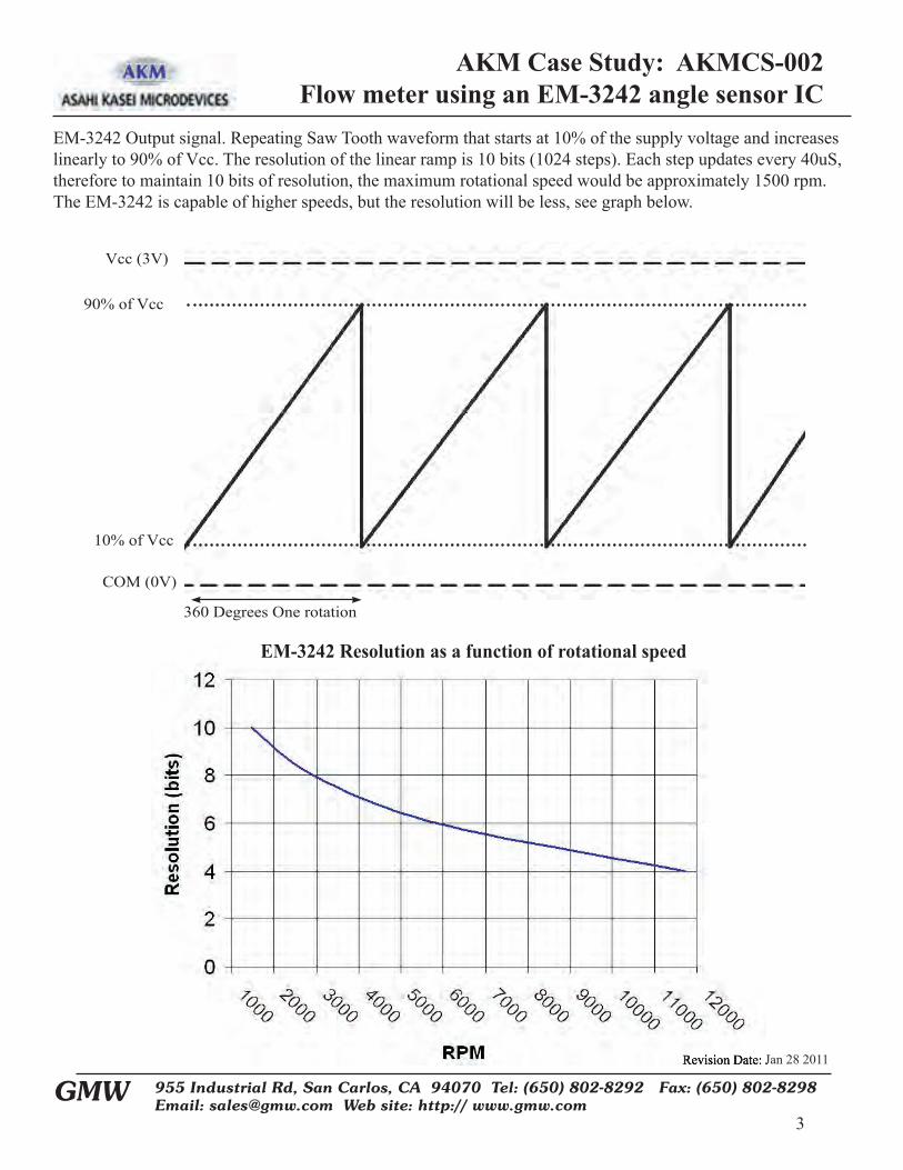
EM-3242 Output signal. Repeating Saw Tooth waveform that starts at 10% of the supply voltage and increases linearly to 90% of Vcc. The resolution of the linear ramp is 10 bits (1024 steps). Each step updates every 40uS, therefore to maintain 10 bits of resolution, the maximum rotational speed would be approximately 1500 rpm. The EM-3242 is capable of higher speeds, but the resolution will be less, see graph below.
Revision Date: Jan 28 2011
EM-3242 Resolution as a function of rotational speed

AKM Case Study: AKMCS-004Non-Contact Accurate Switching with Hall IC’s
Revision Date: 28 Jan 2011
1
955 Industrial Rd, San Carlos, CA 94070 Tel: (650) 802-8292 Fax: (650) 802-8298Email: [email protected] Web site: http:// www.gmw.com
GMW
Problem to be solved:
Customer needs a non-contact magnet activated switch that will provide a very accurate and repeatable switch point for an end of travel application 1) Very accurate switch point 2) Hall based switch in SIP package 3) Activated with a magnet 5) Small size
GMW recommended solution
GMW presented a solution to use an AKM EW-752B Unipolar Switching IC. The EW-752B has a bipolar transistor output with an internal 5K pull up resistor. The EW-752B has a wide range operating voltage of 3 to 26V and a switch operate point Bop between 4mT and 10mT, typically = 6mT. The switch turns ON when the South pole field facing the sensor with the marking, exceeds the Bop point. See blow the basic operating characteristics.
EW-752B
AKM Case Study: AKMCS-004Non-Contact Accurate Switching with Hall IC’s
Revision Date: 28 Jan 2011
2
955 Industrial Rd, San Carlos, CA 94070 Tel: (650) 802-8292 Fax: (650) 802-8298Email: [email protected] Web site: http:// www.gmw.com
GMW
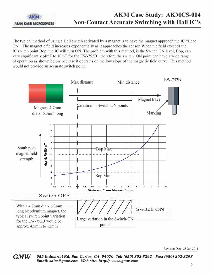
The typical method of using a Hall switch activated by a magnet is to have the magnet approach the IC “Head ON”. The magnetic field increases exponentially as it approaches the sensor. When the field exceeds the IC switch point Bop, the IC will turn ON. The problem with this method, is the Switch ON level, Bop, can vary significantly (4mT to 10mT for the EW-752B), therefore the switch ON point can have a wide range of operation as shown below becuase it operates on the low slope of the magnetic field curve. This method would not provide an accurate switch point.
Switch OFF
Switch ON
Magnet travelVariation in Switch ON points
Max distance Min distance EW-752B
Magnet- 4.7mm dia x 6.3mm long
South pole magnet field
strength
Bop Min
Bop Max
Large variation in the Switch-ON points
Marking
With a 4.7mm dia x 6.3mm long Neodymium magnet, the typical switch point variation for the EW-752B would be approx. 4.5mm to 12mm

AKM Case Study: AKMCS-004Non-Contact Accurate Switching with Hall IC’s
Revision Date: 28 Jan 2011
3
955 Industrial Rd, San Carlos, CA 94070 Tel: (650) 802-8292 Fax: (650) 802-8298Email: [email protected] Web site: http:// www.gmw.com
GMW
TECHNIQUE FOR IMPROVING SWITCHING POINT PRECISION
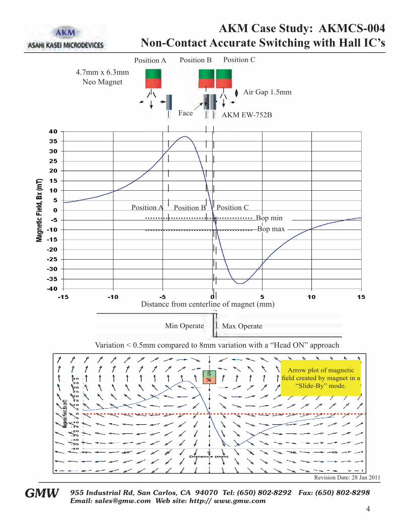
The best way to create an accurate switch point with a Hall switch IC, is to operate it in “Slide-By” mode. IN a “Slide-By” mode, the magnet passes by the sensor with the magnet pointing toward the top of the IC rather than the face of the IC. The illustration below shows the magnetic fi eld as related to three different positions between the magnet and the IC. As the magnet approaches the IC, the magnetic fi eld into the IC increases the fi eld in the North direction (position A). As it passes over the IC , the fi eld rapidly changes direction and passes through zero toward the South direction (Position B). As the fi eld increases in the South direction, the IC responds to a South pole switch point, Bop and turns ON as shown in Position C. The “key” in obtaining an accurate switch point is operating the sensor in the steep portion of the fi eld change. In this case, the variances in the Bop point from sensor to sensor, is very minimal. The stronger the magnet and the closer the sensor is to the magnet, the steeper the curve and therefore the more accurate the switch point will be.
Below is the arrow plot as a result of magnetic modeling analysis of the magnet. The exponential curve in the plot below represents the fi eld strength in the “X” direction as a function of distance from the magnet face
AKM Case Study: AKMCS-004Non-Contact Accurate Switching with Hall IC’s
Revision Date: 28 Jan 2011
4
955 Industrial Rd, San Carlos, CA 94070 Tel: (650) 802-8292 Fax: (650) 802-8298Email: [email protected] Web site: http:// www.gmw.com
GMW
Position A Position B Position C
Face
Position A Position B Position CBop minBop max
AKM EW-752B
4.7mm x 6.3mm Neo Magnet
Air Gap 1.5mm
SN
Min Operate Max Operate
Variation < 0.5mm compared to 8mm variation with a “Head ON” approach
Arrow plot of magnetic fi eld created by magnet in a
“Slide-By” mode.
Distance from centerline of magnet (mm)

AKM Case Study: AKMCS-004Non-Contact Accurate Switching with Hall IC’s
Revision Date: 28 Jan 2011
5
955 Industrial Rd, San Carlos, CA 94070 Tel: (650) 802-8292 Fax: (650) 802-8298Email: [email protected] Web site: http:// www.gmw.com
GMW
Sensor B
Sensor A
A
BSensor A + Sensor B
TOP DEAD CENTER SENSINGThis technique is also very useful in creating a very narrow “Top Dead Center “ timing pulse. This is accomplished by placing two EW-752B IC’s back to back and having one switch turn ON just before the other IC is Turned Off. By combining the two outputs when they are both ON using a NAND gate, a very narrow and very accurate pulse can be created.. The width of the pulse is based on the distance between two sensors which is about 1mm when they are placed back to back. For a linear movement, the pulse width in seconds, would be the speed of the magnet in Sec/mm * 1mm. The physical width would be 1mm. For an angle sweep, the pulse width in degrees would be: ∆θ ≈ (1mm *360º)/� * D(mm) EG: for D=50mm, ∆θ~ (1mm *360º)/� * 50mm)~2.3°
B Sensor Turn Off
Sensor A Sensor B
Magnet travel
Two EW-752B facing back to back
Sensor A is turned ON by the South pointing fi eld ( Right to Left)
Sensor B is turned ON by the North pointing fi eld (Left to Right)
Magnetic FieldPlots from moving A Sensor Turn ON
4.7mm x 6.3mm Neo Magnet Air Gap 1.5mm

GMW Associates www.gmw.com 650-802-8292
Demonstrator for the AKM AK8775 ands AK8776 Magnetic Encoder IC’s
Features:•Self Contained 9V Battery Operated – Power ON/OFF switch
•Output LED indicators
•Motor driven ring magnets 4PP and 8PP
•Two Speed Switch
•Forward – Reverse Switch
•Output terminals for external connections and monitoring
AKM Magnetic Encoder IC Demonstrator

GMW Associates www.gmw.com 650-802-8292
Price List
AKM Hall Element KITs
AN_161KITs............................................................................................... $35
AN_160KIT Universal Hall Interface Amplifier........................................ $35
Gapped Core Current Sensor KITs using the AKM EQ-73XL Series Linear ICs
AN_130KIT EQ-730L ................................................................................ $35
AN_131KIT EQ-731L ................................................................................ $35
AN_135KIT EQ-733L ................................................................................ $35
AN_136KIT EQ-733L ................................................................................ $35
CQ-121/131 Series Current Sensors KITS
AN_165KIT................................................................................................. $35
EM3242 Non-Contact Angle Sensor IC KITs
AN_133KIT................................................................................................. $30AN_134KIT................................................................................................. $30
Demonstrators
AK8775/6 Encoder ICs............................................................................ $375
CQ-20XX Series Current Sensors KITS
AN_170KIT................................................................................................. $35


![Covert Channels Using Mobile Device’s Magnetic Field Sensors · magnetic sensors, also called magnetometers. As the in-dustrial cost of magnetic sensors is very low [14], they are](https://static.fdocuments.in/doc/165x107/5f484cb0c102e5416e04ffc3/covert-channels-using-mobile-deviceas-magnetic-field-sensors-magnetic-sensors.jpg)