
AK: Juneau Manual of Stormwater Best Management Practices
235
Alaska Department of Environmental Conservation Division of Water 555 Cordova Street Anchorage, Alaska 99501 June 2009
-
Upload
sotirakou964 -
Category
Documents
-
view
3.227 -
download
1
Transcript of AK: Juneau Manual of Stormwater Best Management Practices

Alaska Department of Environmental Conservation
Division of Water
555 Cordova Street
Anchorage, Alaska 99501
June 2009

This page intentionally left blank

Alaska Storm Water Guide June 2009
i
Preface
This Guide was developed with support of a technical workgroup under the direction of the
Alaska Department of Environmental Conservation. A list of contributors and participants in
the process appears in the Acknowledgements section. During the development of the
Guide, care was taken to focus on the goal of producing a useful document that helps
contractors and storm water practitioners better manage storm water under the unique
conditions that are encountered in Alaska. In addition to proving useful information about
storm water regulated under the National Pollutant Discharge Elimination System, the Guide
partially fulfills Alaska’s requirements toward gaining approval of the New Development
Management Measure under its Coastal Nonpoint Pollution Control Program.
Many states and communities nationwide have adopted urban storm water quality
requirements, resulting in the need to implement storm water best management practices
under many different physical and climatic conditions. The public and the engineering
community have rightfully expressed some concern over how such structures perform in
Alaska. The Guide tries to address some of the unique challenges posed by the diversity of
Alaska’s geography, geology and climate and makes some generalized recommendations
about the design and selection of storm water best management practices in an effort to
optimize their effectiveness.
The Guide takes advantage of many additional tools created over the years and provides
links to some of the most useful information. It does not address in detail the requirements
of non-storm water-related regulatory programs that can have an effect on storm water. The
Guide tries to not duplicate the many good sources of information already available and
often foregoes detailed explanation of a particular element and refers the reader directly to
the original resource by means of a link or cited reference.
The Guide is intended to be flexible, easily updated and responsive to the needs of the
Alaska storm water community. The concepts presented in this Guide are intended to be
guidance for readers rather than stringent rules. The Guide embraces the concept that each
storm water problem is different, so solutions will need to be customized to address this
variability.

Alaska Storm Water Guide June 2009
ii
This page intentionally left blank
Alaska Storm Water Guide June 2009
iii
Acronyms
ADEC Alaska Department of Environmental Conservation
BMP best management practice
BOD biochemical oxygen demand
cfs cubic feet per second
CFR Code of Federal Regulations
CGP construction general permit
CN curve number
CNPCP Coastal Nonpoint Pollution Control Program
COD chemical oxygen demand
COE United States Army Corps of Engineers
CWA Clean Water Act
CZMA Coastal Zone Management Act
DO dissolved oxygen
ED extended detention
EPA U.S. Environmental Protection Agency
FEMA Federal Emergency Management Agency
fps feet per second
HSG hydrologic soil group
LID low impact development
MOA Municipality of Anchorage
MSGP Multi-sector general permit
MS4 Municipal separate storm sewer system
N Nitrogen
NFIP National Flood Insurance Program
Alaska Storm Water Guide June 2009
iv
NOAA National Oceanic and Atmospheric Administration
NPDES National Pollutant Discharge Elimination System
NRCS U.S. Department of Agriculture, Natural Resource and Conservation
Service (formerly the SCS Soil Conservation Service)
NWI National Wetlands Inventory
NWS National Weather Service
O&M operation and maintenance
P Phosphorus
SDWA Safe Drinking Water Act
SWMP Storm Water Management Program
SWPPP storm water pollution prevention plan
TMDL total maximum daily load
TN total nitrogen
TP total phosphorus
TP 47 Technical Publication 47 of the National Weather Service
TSS total suspended solids
WQ water quality

Alaska Storm Water Guide June 2009
v
Acknowledgements
This Guide was prepared for the Alaska Department of Environmental Conservation (ADEC)
under Contract Number 18-2011-28. The authors are Jim Collins, John Kosco, Regina
Scheibner and John Swanson of Tetra Tech, Inc., and Tom Schueler of the Chesapeake
Stormwater Network. William Ashton was the ADEC Project Manager. Technical workgroup
members and their affiliation are listed below:
Workgroup Members
Kris Benson Alaska Department of Transportation and Public Facilities
Michele Elfers City and Borough of Juneau
Mel Langdon Municipality of Anchorage
Jackson Fox City of Fairbanks
Chuck Kaucic Matanuska-Susitna Borough
Robert Ruffner Kenai Watershed Forum
Bardie Scarbrough Granite Construction
Mike Travis Travis/Peterson Environmental Consulting
Jim Watterson Watterson Construction
Jim Weed Weed Engineering
Stoney Wright Alaska Department of Natural Resources
Misha Vakoc EPA Region 10
Paul Lacsina Municipality of Anchorage
Steve Ellis Municipality of Anchorage
Julie Congdon EPA Region 10
Andy Nolen Alaska Department of Natural Resources
Tom Weed Weed Engineering
Jennifer Schmetzer Fairbanks North Star Borough

Alaska Storm Water Guide June 2009
vi
This page intentionally left blank

Alaska Storm Water Guide June 2009
vii
Contents
Preface ....................................................................................................................................................i
Acronyms..............................................................................................................................................iii
Acknowledgments ................................................................................................................................v
Chapter 1 Overview of Storm Water Regulations ......................................................................... 1-1 1.0 Introduction .......................................................................................................................... 1-1 1.1 Federal .................................................................................................................................. 1-1
1.1.1 NPDES Storm Water Program (Municipal, Industrial and Construction)...................1-2
1.1.2 Coastal Zone Act Reauthorization Amendments (CZARA) Section 6217.................1-9
1.1.2.1 New Development Management Measure............................................... 1-10
1.1.2.2 Watershed Protection Management Measure ......................................... 1-12
1.1.2.3 Site Development Management Measure................................................ 1-12
1.1.2.4 Planning, Siting and Developing Roads and Highways Management Measure ............................................................................. 1-12
1.1.2.5 Operation and Maintenance Management Measure................................ 1-13
1.1.2.6 Road, Highway and Bridge Runoff Systems Management Measure....... 1-13
1.1.2.7 Other Federal Guidance........................................................................... 1-13 1.1.3 UIC Program ........................................................................................................... 1-14
1.1.4 U.S. Army Corps of Engineers................................................................................ 1-16
1.2 State .................................................................................................................................... 1-17 1.2.1 Regulations for Storm Water Disposal Plans.......................................................... 1-17
1.2.2 Review of NPDES Industrial and Construction SWPPP......................................... 1-18
1.2.3 Dewatering Permits................................................................................................. 1-19
1.2.4 Contained Water Discharge Permits ...................................................................... 1-20
1.3 Local Requirements........................................................................................................... 1-21 1.3.1 Municipality of Anchorage and Alaska Department of Transportation
& Public Facilities.................................................................................................... 1-21
1.3.2 The City of Fairbanks, City of North Pole, University of Alaska Fairbanks and Alaska Department of Transportation & Public Facilities................................. 1-24
1.3.3 Fairbanks North Star Borough ................................................................................ 1-26
1.3.4 Other Local Authorities ........................................................................................... 1-26
1.3.5 Land Development Considerations for Storm Water Management........................ 1-26
1.4 Water Quality...................................................................................................................... 1-26 1.4.1 Standards and Criteria ............................................................................................ 1-26
1.4.2 Pollutants of Concern.............................................................................................. 1-27
Sediments/Solids .................................................................................................... 1-29
Nutrients .................................................................................................................. 1-30
Metals .................................................................................................................. 1-30
Pathogenic Bacteria................................................................................................ 1-31
Alaska Storm Water Guide June 2009
viii
pH ............................................................................................................................1-31
Biochemical Oxygen Demand (BOD), Trace Organics and Litter ...........................1-31 1.4.3 Additional Water Quality Considerations.................................................................1-32
1.5 Enforcement and NPDES Primacy....................................................................................1-34
Chapter 2 Storm Water Considerations for Alaska........................................................................2-1 2.0 Introduction...........................................................................................................................2-1 2.1 Why Urban Storm Water Matters to Alaska Streams ........................................................2-1 2.2 Rainfall, Snowfall, Climate and Soils..................................................................................2-3 2.3 Treatment of Runoff and Snowmelt....................................................................................2-8 2.4 Storm Water Design Constraints in Alaska .....................................................................2-13 2.5 Storm Water Management in an Era of Climate Change ................................................2-15 2.6 Winter Construction ...........................................................................................................2-16 2.7 Storm Water Pollution Hotspots .......................................................................................2-17
Chapter 3 Storm Water Design Considerations and Methods......................................................3-1
3.0 Introduction ..............................................................................................................................3-1 3.1 The Role of Soils...................................................................................................................3-2
High Infiltration Soils ..................................................................................................3-3
Moderate Infiltration Soils ..........................................................................................3-3
Low Infiltration Soils...................................................................................................3-3
Saturated Soils ..........................................................................................................3-4
Overview of Soil Hydrologic Analysis ........................................................................3-4
3.2 Considerations for Protecting Sensitive Receiving Waters.............................................3-7 3.2.1 Drinking Water Source Protection .............................................................................3-7
3.2.2 Anadromous Fish Habitat and Other Resource Protection Areas.............................3-7
3.2.3 Construction Adjacent to Wetlands and Discharges to Wetlands .............................3-8
Municipal Wetlands Management Efforts ..................................................................3-8
ADEC Wetlands Assessment Efforts.........................................................................3-8 3.2.4 Impaired Waters (Includes a Map or Source for Maps; 303(D) List; TMDLs) ...........3-9
3.3 Design Considerations for Alaska ......................................................................................3-9 3.3.1 Water Quality Volume Criteria .................................................................................3-12
3.3.2 Groundwater Recharge Volume Criteria .................................................................3-15
3.3.3 Channel Protection Criteria .....................................................................................3-15
Accepted Analytical Methods for Assessing Channel Protection............................3-16 3.3.4 Flood Control Criteria...............................................................................................3-16
Accepted Modeling Software or Analytical Approaches for Assessing Flood Potential.........................................................................................................3-20
3.3.5 Low Impact Development/Environmental Site Design ............................................3-20
Information Sources Related to LID for Alaska Designers......................................3-21
3.4 Storm Water Situation Considerations.............................................................................3-22 3.4.0 Introduction ..............................................................................................................3-22
3.4.1 Storm Water Strategies for Urban, Suburban and Rural Areas ..............................3-22
Alaska Storm Water Guide June 2009
ix
3.4.2 Linear Projects ........................................................................................................ 3-24
3.4.3 Spatial Projects (e.g., malls and high-density subdivisions)................................... 3-26
3.4.4 Mining Considerations ............................................................................................ 3-28
3.4.5 Cold Climate Considerations .................................................................................. 3-29
Winter and the Design of Erosion and Sediment Controls ..................................... 3-29
Snow Storage and Disposal Controls ..................................................................... 3-33
Cold-Climate Design of Permanent Storm Water Controls .................................... 3-33 3.4.6 Pulling It All Together: Choices in Local Storm Water Design Manuals................. 3-34
Chapter 4 Temporary Storm Water Controls ................................................................................. 4-1 4.0 Introduction .......................................................................................................................... 4-1 4.1 Erosion and Sediment Control (ESC) Principles.............................................................. 4-1
Erosion Prevention.....................................................................................................4-2
Erosion Control ..........................................................................................................4-2
Sediment Control .......................................................................................................4-3
BMP Treatment Train.................................................................................................4-3
Keys to Effective ESC................................................................................................4-4
4.2 Construction SWPPP Development................................................................................... 4-7 4.3 Erosion and Sediment Control BMPs ................................................................................ 4-9 4.4 Good Housekeeping BMPs............................................................................................... 4-50 4.5 Inspections, Maintenance and Recordkeeping............................................................... 4-64
Construction Site Inspections ................................................................................. 4-64
Inspection Reports .................................................................................................. 4-64
Maintaining BMPs ................................................................................................... 4-65
Recordkeeping........................................................................................................ 4-66
4.6 Common Problems with SWPPPs and Temporary BMPs ............................................. 4-67
Chapter 5 Permanent Storm Water Management Controls .......................................................... 5-1 5.0 Introduction .......................................................................................................................... 5-1 5.1 Selecting Permanent Storm Water Controls ..................................................................... 5-2
Storm Water Treatment Suitability Matrix ..................................................................5-3
5.2 Low Impact Development/Environmental Site Design Concepts ................................... 5-5 LID Techniques..........................................................................................................5-5
5.3 Source Control Practices for High Pollutant Source Hotspots....................................... 5-6 5.4 Permanent Storm Water BMPs........................................................................................... 5-8 5.5 Maintenance ....................................................................................................................... 5-34
Glossary
References
Appendix A: Links to Relevant Web Pages

Alaska Storm Water Guide June 2009
x
This page intentionally left blank

Alaska Storm Water Guide June 2009
Chapter 1: Overview of Storm Water Regulations 1-1
Chapter 1 Overview of Storm Water Regulations
1.0 Introduction
Storm water is the surface runoff that results from rain and snowmelt that flows over land or
impervious surfaces. Urban development alters the land’s natural retention and absorption
capabilities, and human activity generates a host of pollutants (i.e., sediment, oil and
grease, pesticides, or other toxics) that can accumulate on impervious surfaces, such as
roofs, roads, sidewalks, and parking lots, which can be picked up by storm water runoff as it
moves across these surfaces. Uncontrolled storm water discharges from urban, suburban,
and industrial areas can negatively affect water quality and be detrimental to aquatic life,
wildlife, habitat and human health.
This chapter presents background information on regulatory programs related to storm water
runoff at the federal, state and local levels. This information addresses who is regulated,
what to do to comply with requirements, where the regulated jurisdictions in Alaska are
located and tips on how to obtain additional information.
1.1 Federal
In coordination with states, the regulated community and the public, the U.S. Environmental
Protection Agency (EPA) implements the National Pollutant Discharge Elimination System
(NPDES) permit program on the basis of statutory requirements in the federal Clean Water
Act (CWA) to control discharges of pollutants to waters of the United States from point
sources. Initial efforts to improve water quality using the NPDES program focused primarily
on reducing pollutants from industrial process wastewater and municipal sewage
discharges. In 1987 Congress amended the CWA to require, in two phases, a
comprehensive national program for addressing storm water discharges from urban,
industrial and construction activities using the NPDES permit program. For more details on
the NPDES storm water permit program, see Section 1.1.1.
Alaska Storm Water Guide June 2009
1-2 Chapter 1: Overview of Storm Water Regulations
In 1990 Congress passed the Coastal Zone Act Reauthorization Amendments (CZARA) to
address nonpoint source (NPS) pollution problems in coastal waters. To qualify for federal
funding, coastal states such as Alaska must describe how they implement appropriate NPS
pollution controls, known as management measures, within the coastal zone. For more
information concerning these materials, see Section 1.1.2.
The federal Safe Drinking Water Act established the Underground Injection Control (UIC)
Program to protect underground sources of drinking water (USDWS) by regulating the
subsurface discharge of both hazardous and nonhazardous pollutants through injection
wells. Storm water runoff that discharges to the ground may in some cases impact
subsurface water resources. Section 1.1.3 has additional information on this subject.
Information on CWA section 404 permitting is presented in Section 1.1.4.
EPA and other federal agencies have produced various recommendations and guidance
materials for the management of storm water runoff. For example, the appropriate design
and maintenance of roads, particularly gravel or unpaved roads, can protect water quality by
limiting polluted discharges from road surfaces. Low impact development (LID) techniques
emphasize the use of on-site retention of storm runoff in areas of new development and
redevelopment. For more information about this information, see Section 1.1.5.
1.1.1 NPDES Storm Water Program (Municipal, Industrial and Construction)
As mentioned previously, most states are authorized to issue permits under the NPDES
storm water program, Alaska is under a phased transition to assume primacy for NPDES
permitting. On October 31, 2008, EPA formally approved Alaska’s NPDES program
application. The state’s approved program is called the Alaska Pollutant Discharge
Elimination System (APDES) Program. Authority over the federal permitting and compliance
and enforcement programs began to transfer to the Alaska Department of Environmental
Conservation (ADEC) over a 3-year period beginning at program approval. Until authority
over a facility transfers to ADEC, EPA will remain the permitting and compliance and
enforcement authority for that facility. Authority for the storm water program is scheduled to
transfer on October 31, 2009; from then forward ADEC will be the permitting authority for
storm water in Alaska. (For more information about ADEC’s NPDES delegation, see
Section 1.5.)
The NPDES storm water permit requirements are based largely on a pollution-prevention
approach. The most effective storm water management techniques emphasize preventing
rain and snowmelt from coming into contact with pollutants, and preventing discharges
directly to nearby receiving waters. NPDES storm water permits require operators of
Alaska Storm Water Guide June 2009
Chapter 1: Overview of Storm Water Regulations 1-3
permitted activities or systems to use best management practices (BMPs) designed to
effectively protect water quality for their particular site conditions and activity.
The NPDES storm water permit program specifically regulates three types of storm water
discharges: storm water from certain municipal separate storm sewer systems (MS4s),
discharges of storm water associated with industrial activity, and storm water from
construction sites disturbing one or more acres.
Municipal storm water permit requirements. Operators of MS4s that serve a certain size
population must obtain authorization to discharge pollutants under an NPDES permit. An
MS4 is a conveyance or system of conveyances that discharges to waters of the United
States, which is
designed or used for collecting or conveying storm water;
owned by a state, city or other public body; and
not part of a combined sewer system or publicly owned treatment works.
MS4s can therefore be owned or operated by municipalities, boroughs, state departments of
transportation or federal entities. However, only those MS4s serving communities of a
certain population size, according to the latest Decennial Census, are required to obtain
NPDES permits. In general, regulated MS4s in areas with more than 100,000 people
according to the 1990 Census, or in Urbanized Areas according to the 2000 Census, are
subject to the NPDES permit program. At this time, only the greater Anchorage and
Fairbanks areas are considered Urbanized Areas according to the U.S. Bureau of the
Census. MS4s within these areas include the Municipality of Anchorage, Alaska Department
of Transportation and Public Facilities (ADOT&PF), Cities of North Pole and Fairbanks,
Fairbanks North Star Borough, University of Alaska-Fairbanks, and Department of Defense
facilities (for more details, see Section 1.3).
Operators of regulated MS4s develop comprehensive storm water management programs
(SWMPs) designed to control pollutants to the maximum extent practicable, prohibit non-
storm water (i.e., illicit) discharges to their MS4, and protect water quality by controlling
storm water discharges from construction activities, new development and redevelopment
areas. Other than Anchorage, which is governed by the Phase I MS4 regulations, municipal
SWMP requirements follow six minimum measures:
Public education and outreach, to educate the community about the water quality;
Public involvement program to engage the public in pollutant reduction strategies;
Illicit discharge detection and elimination program, to specifically prohibit non-storm water discharges from entering the MS4;

Alaska Storm Water Guide June 2009
1-4 Chapter 1: Overview of Storm Water Regulations
Construction site runoff control program, to create locally appropriate requirements for site plan review and using controls to limit erosion, sedimentation, and improper management of onsite construction materials;
Post-construction runoff control program, to integrate storm water management techniques into land development planning/zoning procedures to provide long-term storm water management in areas of new development and redevelopment; and
Pollution prevention/good housekeeping program, to ensure that municipal maintenance activities of streets, roads, parks, and so on, are not causing unintended water quality problems.
Detailed information about these requirements can be obtained from resources listed at the
end of this chapter.
The operator of a regulated MS4 must define its water quality protection goals through the
SWMP. EPA and ADEC use annual reports of program implementation to evaluate progress
toward meeting water quality goals and limiting pollutants in municipal storm water
discharges to the maximum extent practicable. Examples of appropriate water quality goals
include pollution-prevention measures (reducing potential pollutants at the source),
improvements in storm water outfall discharge quality, reducing pollutant loads to receiving
waters, restoring aquatic resources (e.g., stream channel stabilization, fishery restoration),
compliance with water quality standards, or restoring beneficial uses in the receiving water.
Intermediate benchmarks that indicate incremental progress toward meeting water quality
standards are important elements of successful, long-term SWMPs. Additional information
about the NPDES MS4 program is at Link 1 in Appendix A.
Industrial storm water permit requirements. Industrial activities often involve the outdoor
storage and handling of raw or finished materials, which are exposed to rain and snow. As
runoff from rain or snowmelt comes into contact with such materials, it picks up pollutants
and transports them to nearby storm sewer systems, rivers, lakes, or coastal waters. EPA
regulations define 11 categories of industrial activities by Standard Industrial Classification
(SIC) code Operators must obtain NPDES permit coverage to discharge storm water to an
MS4 or directly to waters of the United States. The list below describes the types of
industrial activities within each category.
Category One (i): Facilities with effluent limitations
Category Two (ii): Manufacturing
Category Three (iii): Mineral, Metal, Oil and Gas
Category Four (iv): Hazardous Waste, Treatment or Disposal Facilities
Alaska Storm Water Guide June 2009
Chapter 1: Overview of Storm Water Regulations 1-5
Category Five (v): Landfills
Category Six (vi): Recycling Facilities
Category Seven (vii): Steam Electric Plants
Category Eight (viii): Transportation Facilities
Category Nine (ix): Treatment Works
Category Ten (x): Construction Activity
Category Eleven (xi): Light Industrial Activity
Note that Category Ten (x): Construction Activity, which disturbs 5 or more acres of land, is
included in the definition of “storm water discharges associated with industrial activity.”
However, EPA opted to permit these types of activities separately from other industrial
activities because of the significant difference in the nature of the activities. In addition, EPA
requires permit coverage for small construction that disturbs from 1 to 5 acres of land.
NPDES permits for industrial storm water discharges generally require the development and
implementation of a site-specific storm water pollution prevention plan (SWPPP) to define
the control measures to be used at the facility to control sources of pollution and to eliminate
pollution in storm water discharges to meet state water quality standards.
On September 29, 2008, EPA reissued the general permit for storm water discharges
associated with industrial activity, also referred to as the 2008 Multi-Sector General Permit
(MSGP). The previous version of the MSGP, the MSGP 2000, expired on October 30, 2005,
and facilities that were previously covered by the MSGP 2000 have been covered by an
administrative continuance, and will continue to be covered in this manner, until their
authorization under the new permit. The 2008 MSGP divides the 11 categories into 29
different industrial sectors. The 2008 MSGP contains provisions that require industrial
facilities in each industrial sector to submit a complete and accurate Notice of Intent (NOI) to
be covered and certify in the NOI that they meet the requisite eligibility requirements of the
permit, including the requirement to select, design and install control measures to comply
with the technology- and water quality-based effluent limits and develop site-specific
SWPPPs. Effective February 26, 2009, specific permit conditions (NPDES Permit No.
AKR050000) that apply to industrial facilities in Alaska are in Part 9 of EPA’s 2008 MSGP.
Detailed information on the 2008 MSGP is on EPA’s MSGP Web site (Link 2 in Appendix A).
EPA Region 10 has also issued other general permits authorizing storm water discharges
for specific industrial categories of industry. For example, NPDES General Permit AKG-33-
0000, which authorizes discharges of storm water for facilities related to oil and gas in the

Alaska Storm Water Guide June 2009
1-6 Chapter 1: Overview of Storm Water Regulations
North Slope Borough. A general permit for log transfer facilities also authorizes the
discharge of storm water and other process wastewater discharges. Details about these
general permits are on EPA Region 10’s Web site (Link 3 in Appendix A).
Construction storm water permit requirements. Storm water runoff from clearing, grading
and excavation activities associated with construction can have a significant effect on water
quality. As storm water flows over an active construction site, it picks up pollutants like
sediment, debris and chemicals. Polluted storm water runoff from construction sites can
harm or kill fish and other wildlife. Sedimentation can destroy aquatic habitat, and high
volumes of runoff can cause stream bank erosion. For these reasons, the NPDES storm
water program requires operators of construction sites that disturb one or more acres of land
(including smaller than one-acre sites that are part of a larger common plan of development
or sale that itself is larger than one acre) to obtain authorization to discharge storm water
under an NPDES construction storm water permit.
EPA’s NPDES General Permit for Storm Water Discharges from Construction Activity (also
known as the Construction General Permit or CGP), was reissued in 2008 (NPDES Permit
No. AKR100000) and authorizes storm water discharges from large and small construction
activities that result in a total land disturbance of equal to or greater than one acre, where
such discharges enter surface waters of the United States or an MS4 leading to surface
waters of the United States. The 2008 CGP has been issued for a 2-year period and
eligibility for coverage under the 2008 CGP is limited to operators of new projects or
unpermitted ongoing projects. A new project is one that begins after the June 30, 2008,
CGP. An unpermitted ongoing project is one that began before the effective date of the 2008
CGP yet never received authorization to discharge under the 2003 CGP or any other
NPDES permit covering its construction-related storm water discharges.
New or unpermitted ongoing construction project operators choosing to be covered by the 2008 CGP must develop an SWPPP and submit a complete and accurate NOI to obtain NPDES permit coverage. The SWPPP must be site-specific and define the control measures that will be installed and implemented at the construction site. The SWPPP must be updated as conditions change on a construction site because of seasonal or operational factors.
Construction site operators that received authorization to discharge under the 2003 CGP are not eligible for coverage under the 2008 permit, and authorization will be automatically continued under the 2003 MSGP until the 2008 CGP expires and the new CGP is issued, or coverage under the 2003 CGP is terminated, whichever is earlier. Note: If you are an operator of a permitted, ongoing project and you transfer ownership of the project, or a portion of it, to a different operator, that operator must submit a complete and accurate NOI as if it were a new project.

Alaska Storm Water Guide June 2009
Chapter 1: Overview of Storm Water Regulations 1-7
Per the 2008 CGP, if you disturb equal to or greater than one acre or are part of a larger
common plan of development or sale that disturbs at least one acre of land, you should do
the following:
Obtain and read the entire CGP before beginning your project. The CGP requires compliance with state and local requirements as well as the CGP requirements
Develop an SWPPP. Development of an SWPPP and implementation of control measures at your construction site are the key conditions of the CGP
Complete an endangered species determination for the project site
Submit an original, signed NOI to EPA, at least 7 days before construction begins. The NOI can be filed through EPA’s electronic NOI system at Web Link 4 in Appendix A or by hard copy
Additional information about the 2008 CGP is on EPA Region 10’s Web site (see Link 5 in
Appendix A).
The 2008 CGP was issued for only a 2-year period because EPA is in the process of
developing a national regulation (called an effluent limitations guideline) for the construction
and development industry. When the rulemaking is complete, EPA will issue an updated
CGP that incorporates the provisions of the effluent guideline as soon as possible, but not
later than July 2010. With ADEC assuming primacy for storm water October 31, 2009,
ADEC is planning on issuing a revised CGP for Alaska prior to July 2010 (see Section 1.5).
For construction projects in Alaska that disturb at least one acre of land but less than 5
acres of land, the operator will have to provide a copy of the NOI to ADEC at the same time
it is submitted to EPA. If the construction project disturbs 5 acres or more and is outside the
Municipality of Anchorage (MOA), the City of Fairbanks, the City of North Pole or Fairbanks
North Star Borough (FNSB) or for certain publicly funded projects within the jurisdictions of
the MOA or Fairbanks, the operator will have to provide a copy of the SWPPP to ADEC for
review. The SWPPP must be accompanied by the state-required plan review fee in the
amount determined by using Table D of 18 AAC 72.995 and made payable to State of
Alaska – DEC.
Public projects disturbing 1 or more acres within the Urbanized Area of the City of Fairbanks
and the City of North Pole need to submit an NOI and SWPPP to ADEC (see Table 1-2 and
the 2008 CGP). If a privately funded project disturbs one or more acres and is within the
jurisdictions of the MOA, the City of Fairbanks, City of North Pole or the FNSB, the operator
will have to provide a copy of the SWPPP to the municipality, along with any applicable fee.
Note that the FNSB MS4 is defined very specifically as storm water conveyance systems
Alaska Storm Water Guide June 2009
1-8 Chapter 1: Overview of Storm Water Regulations
located within Road Service Areas in the Urbanized Area. FNSB will review both public and
private projects that disturb more than one acre of land and discharge storm water to the
MS4 (i.e., storm water conveyance systems located within a Road Service Area in the
Urbanized Area). Projects that do not meet these criteria will be referred to ADEC for review.
Projects that are within the Fairbanks Urbanized Area boundary but outside the city limits for
the City of Fairbanks and the City of North Pole are only regulated by the FNSB if the project
impacts the municipal separate storm sewer system within a FNSB Road Service
Area. Regulation would apply to both publicly- and privately-funded projects.
In addition, hardrock mines that are designed to process 500 or more tons per day, the
operator must provide a copy of the SWPPP to ADEC for review at least 90 days before the
start of construction. For more detail, see Part 10 of the 2008 CGP and Section 1.2.2.
Will EPA review my SWPPP? Typically EPA will not review SWPPPs; instead ADEC or MOA, or the City of Fairbanks and FNSB will complete this review. Occasionally, EPA may request a copy of your SWPPP for review, either through a letter or at the time of an inspection.
If ADEC, MOA, the City of Fairbanks and FNSB reviews my SWPPP and has no objections to it, can I assume it is in compliance with the requirements in the CGP? Not necessarily. Submittal of the SWPPP to MOA, the City of Fairbanks, FNSB or ADEC is a requirement of the CGP, but each of these agencies reviews the document with its own objectives in mind. ADEC reviews SWPPPs to make sure they contain each of the necessary elements outlined in the CGP, but it cannot evaluate the thoroughness of each SWPPP element, the appropriateness of selected storm water controls or whether the SWPPP is being kept up-to-date throughout the project. The MOA, the City of Fairbanks and FNSB review SWPPPs for compliance with local erosion and sediment control ordinances. In either case, it is possible for you to be in compliance with ADEC, MOA, City of Fairbanks or FNSB directives and to be found in violation of the SWPPP requirements in the CGP. For this reason, you should make sure that you have read the CGP carefully and understand the requirements before proceeding with your project.
Who conducts inspections and what are the objectives of each inspection? ADEC, MOA, the City of Fairbanks, FNSB and EPA have the authority to conduct inspections at your construction site; however, the objective of each inspection depends on the agency. EPA inspectors assess a facility’s compliance with the CGP and the CWA; ADEC inspectors assess a facility’s compliance with Alaska Water Quality Standards; and MOA or City of Fairbanks and FNSB inspectors assess a facility’s compliance with local ordinances. Some state rules and local erosion and sediment control ordinances might overlap with the requirements in EPA’s CGP; however, you should not assume that a directive from any one of these agencies will bring you into compliance with the requirements of the other two. After October 31, 2009, ADEC, not EPA, will be conducting inspections (for details, see Section 1.5).

Alaska Storm Water Guide June 2009
Chapter 1: Overview of Storm Water Regulations 1-9
If you have further questions about how to comply with requirements for construction sites in Alaska, contact the following representatives:
Julie Congdon EPA Region 10 1200 Sixth Avenue OWW-130555 Seattle, WA 98101 (800) 424-4372, ext. 2752
Greg Drzewiecki ADEC Storm Water Coordinator 555 Cordova Street Anchorage, AK 99501 (907) 269-7692
Steve Ellis Municipality of Anchorage P.O. Box 196650 Anchorage, AK 99519 (907) 343-8078
Jackson Fox City of Fairbanks (also coordinating SWPPP reviews for the City of North Pole) 800 Cushman Street Fairbanks, AK 99701 (907) 459-6758
Jennifer Schmetzer Fairbanks North Star Borough, Department of Public Works P.O. Box 71267, Fairbanks, AK 99707 (907) 459-1327
1.1.2 Coastal Zone Act Reauthorization Amendments (CZARA) Section 6217
CZARA addresses a wide variety of coastal management issues and one of the significant
changes in CZARA was a new section 6217, which established the Coastal Nonpoint
Pollution Control Program (CNPCP). This program was established to encourage better
coordination between state coastal zone managers and water quality regulators to reduce
polluted runoff in the coastal zone. Any state that chooses to participate in the voluntary
national Coastal Zone Management (CZM) Program must develop a CNPCP. At the time
CZARA was passed, only 29 states were participating in the national CZM program, but now
there are 34, including Alaska.
The CNPCP is unique because it establishes a set of management measures for states to
use in controlling polluted runoff from areas not subject to NPDES MS4 regulations. The
measures are designed to control runoff from six main sources: forestry, agriculture, urban
development, marinas, hydromodification (shoreline and stream channel modification), and
protection of wetlands and riparian areas. These measures need to be backed by
enforceable state policies and actions, i.e., state authorities that will ensure implementation
of the program. EPA and the National Oceanic and Atmospheric Administration (NOAA)
conditionally approved Alaska’s CNPCP. For full approval, Alaska needs to address several
remaining conditions, including the urban new development measure.
To be eligible for federal CZM funding, coastal states or territories were required to describe
how they would implement NPS pollution controls, known as management measures, that
conformed to those described in the Guidance Specifying Management Measures for
Sources of Nonpoint Pollution in Coastal Waters (USEPA 1993).
Additional information about the 6217 Program is at Link 6 in Appendix A.
Alaska’s Coastal Nonpoint Program (CNP) boundary follows its CZM boundary, which
extends from 2,000 feet to 250 miles inland along its entire coast. For details, see Link 7 in

Alaska Storm Water Guide June 2009
1-10 Chapter 1: Overview of Storm Water Regulations
Appendix A. However, for the urban management measures, specifically the new
development measure that this manual most directly addresses, Alaska sufficiently
demonstrated that NPS from new development activities is not a significant contributor to
NPS in northern and western portions of the 6217 boundary and 18 small communities in
southern Alaska. Therefore, NOAA and EPA agreed with the state’s targeted approach,
which would focus on implementing the new development measure within the 14
communities and census tracts listed below and shown in Figure 1-1 (the ones with larger
population centers) would be acceptable. Alaska still has to implement other CNP
management measures throughout its CNPCP boundary.
Bethel
Homer
Juneau
Kalifornsky
Kenai
Ketchikan
Knik-Fairview
Kodiak
Lakes
Meadow-Lakes
Palmer
Sitka
Tanaina
Wasilla
The 14 affected Alaskan communities should have enforceable policies or mechanisms in
place for implementing the following specific measures for roads, highways and bridges as
well as new development during the planning and construction phases and afterwards.
1.1.2.1 New Development Management Measure 1. By design or performance
a. After construction has been completed and the site is permanently stabilized,
reduce the average annual total suspended solid (TSS) loadings by 80 percent.
For the purposes of this measure, an 80 percent TSS reduction is to be
determined on an average annual basis1, or
b. Reduce the post development loadings of TSS so that the average annual TSS
loadings are not greater than predevelopment loadings, and
2. To the extent practicable, maintain post development peak runoff rate and average
volume at levels that are similar to predevelopment levels.
Applicability: New development, redevelopment and new and relocated roads,
highways and bridges.
1 On the basis of the average annual TSS loadings from all storms less than or equal to the 2-year/24-hour
storm. TSS loadings from storms greater than the 2-year/24-hour storm will not be included in the calculation of the average annual TSS loadings).

Alaska Storm Water Guide June 2009
Chapter 1: Overview of Storm Water Regulations 1-11
Figu
re 1
-1. C
oast
al Z
one
Com
mun
ities

Alaska Storm Water Guide June 2009
1-12 Chapter 1: Overview of Storm Water Regulations
1.1.2.2 Watershed Protection Management Measure Develop a watershed protection program to
1. Avoid conversion, to the extent practicable, of areas that are particularly susceptible
to erosion and sediment loss;
2. Preserve areas that provide important water quality benefits or are necessary to
maintain riparian and aquatic biota; and
3. Site development, including roads, highways and bridges, to protect the extent
practicable the natural integrity of waterbodies and natural drainage systems.
Applicability: New development, redevelopment and new and relocated roads,
highways and bridges.
1.1.2.3 Site Development Management Measure Plan, design and develop sites to
1. Protect areas that provide important water quality benefits and/or are particularly
susceptible to erosion and sediment loss;
2. Limit increases of impervious areas, except where necessary;
3. Limit land disturbance activities such as clearing and grading, and cut and fill to
reduce erosion and sediment loss; and
4. Limit disturbance of natural drainage features and vegetation.
Applicability: All site development activities including those associated with roads,
highways and bridges.
1.1.2.4 Planning, Siting and Developing Roads and Highways Management Measure
1. Plan, site and develop roads and highways to
2. Protect areas that provide important water quality benefits or are particularly
susceptible to erosion or sediment loss;

Alaska Storm Water Guide June 2009
Chapter 1: Overview of Storm Water Regulations 1-13
3. Limit land disturbance such as clearing and grading and cut and fill to reduce erosion
and sediment loss; and
4. Limit disturbance of natural drainage features and vegetation.
Applicability: All site development and land disturbing activities for new, relocated and
reconstructed (widened) roads (including residential streets) and highways to reduce the
generation of NPS pollutants and to mitigate the effects of urban runoff and associated
pollutants from such activities.
1.1.2.5 Operation and Maintenance Management Measure Incorporate pollution-prevention procedures into the operation and maintenance of
roads, highways and bridges to reduce pollutant loadings to surface waters.
Applicability: Existing, restored and rehabilitated roads, highways and bridges.
1.1.2.6 Road, Highway and Bridge Runoff Systems Management Measure Develop and implement runoff management systems for existing roads, highways and
bridges to reduce runoff pollutant concentrations and volumes entering surface waters.
1. Identify priority and watershed pollutant reduction opportunities (e.g., improvements
to existing urban runoff control structures); and
2. Establish schedules for implementing appropriate controls.
Applicability: Existing, resurfaced, restored and rehabilitated roads, highways and
bridges that contribute to adverse effects in surface waters.
It is strongly recommended that local governments and contractors implement the
practices described that will reduce TSS by 80 percent (or no greater than
predevelopment rates) and maintain peak runoff to predevelopment levels. It is also
strongly recommended that the 14 communities identified above work with ADEC and
other states agencies, as appropriate, to revise their storm water ordinances to
incorporate the section 6217 requirements.
1.1.2.7 Other Federal Guidance Consideration of storm water issues related to linear projects, roads in particular, is an
important topic for Alaska storm water managers and is included under the NPDES MS4
and Construction programs as well as the CNPCP mentioned above. To this end, EPA
has developed a maintenance and design manual for gravel roads with a major
Alaska Storm Water Guide June 2009
1-14 Chapter 1: Overview of Storm Water Regulations
emphasis on the maintenance of gravel roads, including some basic design elements.
The purpose of the manual is to provide clear and helpful information for doing a better
job of maintaining gravel roads. The manual is designed for the benefit of elected
officials, managers and grader operators who are responsible for designing and
maintaining gravel roads. The manual is at Web Link 8 in Appendix A.
1.1.3 UIC Program
The UIC (Underground Injection Control) Program is responsible for regulating the
construction, operation, permitting and closure of injection wells that place fluids
underground for storage or disposal. An injection well is a device that places fluid deep
underground into porous rock formations, such as sandstone or limestone, or into or below
the shallow soil layer. These fluids could be water, wastewater, brine (salt water), or water
mixed with chemicals. Injection wells have a range of uses that include waste disposal,
enhancing oil production, mining and preventing salt water intrusion. The UIC Program
defines an injection well as a bored, drilled, or driven shaft; a dug hole that is deeper than it
is wide; an improved sinkhole; or a subsurface fluid distribution system.
Most injection wells in Alaska are relatively simple devices used to emplace fluids into the
shallow subsurface under the force of gravity. Examples include sumps, drywells and
drainfields. The threat posed to ground water quality varies markedly and depends mostly
upon the volume and nature of the fluids injected, well construction and the hydrogeologic
setting. The federal UIC regulations and additional state requirements are based upon a
protective performance standard.
Federal and state UIC regulatory programs are intended to ensure that owners and
operators of injection wells safely operate injection wells to prevent contamination of
underground drinking water resources. There are five classes of injection wells that are
based on similarity in the fluids injected, activities, construction, injection depth, design and
operating techniques. The categorization ensures that wells with common design and
operating techniques are required to meet appropriate performance criteria for protecting
underground sources of drinking water (USDWs). The five classes and what they are used
for are
I Injection of hazardous wastes, industrial nonhazardous liquids, or municipal
wastewater beneath the lowermost USDW
II Injection of brines and other fluids associated with oil and gas production, and
hydrocarbons for storage beneath the lowermost USDW
Alaska Storm Water Guide June 2009
Chapter 1: Overview of Storm Water Regulations 1-15
III Injection of fluids associated with solution mining of minerals beneath the lowermost
USDW
IV Injection of hazardous or radioactive wastes into or above USDWs (these wells are
banned unless authorized under a federal or state groundwater remediation project)
V All injection wells not included in Classes I–IV
In general, Class V wells inject nonhazardous fluids into or above USDWs and are typically
shallow, on-site disposal systems. However, there are some deep Class V wells that inject
below USDWs. Class V injection wells may be regulated as part of the UIC Program,
authorized by the federal Safe Drinking Water Act. Class V wells discharge fluids
underground and include French drains, tile drains, infiltration sumps and percolation areas
with vertical drainage. Class V storm water drainage wells manage surface water runoff
(rainwater or snowmelt) by placing it below the ground surface. They are typically shallow
disposal systems designed to infiltrate storm water runoff below the ground surface but do
not include infiltration trenches filled with stone (with no piping), or excavated ponds,
lagoons and ditches (lined or unlined, without piping or drain tile) with an open surface. EPA
clarified which infiltration devices are regulated as Class V UIC wells in a June 2008 memo
at Link 9 in Appendix A.
Storm water drainage wells can have a variety of designs and can be referred to by other
names including dry wells, bored wells and infiltration galleries. The names can be
misleading, so it is important to note that a Class V well, by definition, is any bored, drilled,
or driven shaft; a dug hole that is deeper than its widest surface dimension; an improved
sinkhole; or a subsurface fluid distribution system (an infiltration system with piping to
enhance infiltration capabilities). Some types of infiltration systems do not meet the
definition of Class V storm water drainage wells. In general, owners/operators of storm water
drainage wells include state and local governments, public or private institutions,
commercial or industrial facilities, community associations and private citizens.
Compliance with federal regulations could include submitting basic inventory information
about the drainage wells to the state or EPA and complying with specific construction,
operation, permitting and closure requirements. The Safe Drinking Water Act requires that
EPA protect USDWs from injection activities, and EPA has set minimum standards to
address the threats posed by all injection wells, including storm water drainage wells. Storm
water injection is a concern because storm water can contain sediment, nutrients, metals,
salts, microorganisms, fertilizers, pesticides, petroleum and other organic compounds that
could harm USDWs.
Alaska Storm Water Guide June 2009
1-16 Chapter 1: Overview of Storm Water Regulations
Class V storm water drainage wells are authorized by rule, which means they may be
operated without an individual permit so long as the injection does not endanger a USDW,
and the owner or operator of the well submits basic inventory information about the well to
EPA Region 10. Inventory submission requirements include the facility name and location,
name and address of a legal contact, ownership of property, nature and type of injection
well(s), and operating status of the well(s). Owners/operators should contact EPA Region 10
before beginning construction of new storm water drainage wells in Alaska. To find out what
is required for existing storm water drainage wells, contact EPA Region 10. In most cases,
only an inventory form must be submitted.
Proper design and siting of storm water drainage wells minimizes the likelihood of accidental
or routine contamination resulting from either poor operational practices or misuse. The five
general categories of BMPs for storm water drainage wells that can be implemented alone
or in combination are siting; design; operation and maintenance; education and outreach;
and proper closure, plugging and abandonment. The appropriateness and effectiveness of
BMPs vary according to the type, design, setting and operation of the well. Additional
information about these BMPs is at Web Link 10 in Appendix A.
General information regarding the UIC program is on EPA’s Region 10 Web site (see
Link 11 in Appendix A).
1.1.4 U.S. Army Corps of Engineers
For many parts of Alaska, construction is in or adjacent to wetlands that are considered to
be waters of the United States. As a result, Alaska developers might need to obtain permits
from the Corps of Engineers (COE) under its section 404 permit rules. Activities that result in
the discharge of dredged or fill material into the waters of the United States require a written
authorization (permit) from the COE. A description of the discharges that require permits, as
well as those that do not, are at Title 33 of the Code of Federal Regulations Part 323 (33
CFR 323). The COE, in reviewing section 404 permit applications, requires avoidance of
impacts and minimization of unavoidable impacts. The COE and EPA promulgated a new
federal mitigation rule in 2008 to clarify how to provide compensatory mitigation for
unavoidable impacts to the nation’s wetlands and streams. The rule enables the agencies to
promote greater consistency, predictability and ecological success of mitigation projects
under the CWA by encouraging watershed-based decisions and emphasizing the mitigation
sequence requiring that proposed projects avoid and minimize potential effects on wetlands
and streams before proceeding to compensatory mitigation. The rule will affect how
mitigation of unavoidable impacts is addressed in some local jurisdictions such as
Anchorage, Juneau or Fairbanks. In addition, a Water Quality Certification (or Waiver
thereof) pursuant to CWA section 401 is required for section 404 permit actions.
Alaska Storm Water Guide June 2009
Chapter 1: Overview of Storm Water Regulations 1-17
The COE–Alaska District and EPA administers the CWA section 404 Permitting Program.
More than 80 percent of all actions subject to section 404 are authorized by the COE via
general permits, which authorize for small projects such activities as placement of outfall
structures, road crossings, utility line backfill, boat ramps, farm buildings and minor
discharges. If an activity has significant effects, it is not covered under the general permit
and must undergo a more extensive regulatory review, including obtaining an individual
permit. Additional information is on the COE wetlands Web site (Link 12 in Appendix A).
1.2 State
ADEC Division of Water's mission is to improve and protect water quality. In this role, ADEC
Establishes standards for water cleanliness
Regulates discharges to waters and wetlands
Provides financial assistance for water and wastewater facility construction, and waterbody assessment and remediation
Trains, certifies and assists water and wastewater system operators and monitors and reports on water quality
The goal of ADEC’s Storm Water Program is to reduce or eliminate pollutants in storm
waters so that pollutants do not reach land or waters of the state. Storm water discharges
are generated by runoff from land and impervious areas such as paved streets, parking lots
and building rooftops, during rainfall and snowmelt events. Storm water discharges often
contain pollutants in quantities that could adversely affect water quality. Storm water
discharges are regulated under the NPDES program, and certain storm water discharges
require an NPDES permit from EPA.
Under the NPDES program, Alaska does not have permitting and enforcement authority.
However, pursuant to section 401 of the CWA, Alaska certifies EPA general permits (MSGP
and CGP). This is commonly known as 401 Certification. Such conditions are shown in both
permits as “Conditions Applicable to Specific States, Indian Country Lands or Territories”
and must be respected by permitees. ADEC can enforce water quality standards and its
own regulations.
1.2.1 Regulations for Storm Water Disposal Plans
Any person who constructs, alters, installs or modifies any part of a storm water treatment
works or disposal system must submit engineering plans to ADEC for review and approval

Alaska Storm Water Guide June 2009
1-18 Chapter 1: Overview of Storm Water Regulations
per 18 AAC 72.600. To obtain approval in the form of a letter of non-objection, an applicant
must submit a short project description containing the following information to ADEC:
Project name
Contact name, address, phone and fax numbers and e-mail address
Project area (total and soil disturbed)
Receiving waterbody and estimated distance from the project site
Methods of runoff flow and treatment (down to the discharge point)
Treatment system's maintenance procedures
Snow storage/disposal
Treatment system sizing estimation (e.g., swale: length, cross section, bank and longitudinal slopes, flow velocity, detention time)
One set of drainage plans clearly showing drainage boundaries and flow directions
Runoff flow calculation is based on a 2-year, 6-hour rain event (before and after the project
is completed). One of the design criteria for projects using oil and grit separators, is that to
obtain an ADEC letter of non-objection for discharge to storm sewers, an applicant must
demonstrate that the proposed oil and grit separator(s) has (have) the ability to remove at
least 50 percent of particles 20 microns in size from storm water runoff
during the 2–year, 6-hour rain event. A separate storm sewer is “a
conveyance or system of conveyances (i.e., ditches, curbs, catch basins, underground
pipes) that is designed or used for collecting or conveying storm water and that discharges
to surface waters of the State.”
All engineering design and calculations must be stamped by Alaska licensed engineer as
required by 18 AAC 72.600 and 18 AAC 72.990.(29).
ADEC has the authority to inspect facilities and require adherence to the approved plans.
1.2.2 Review of NPDES Industrial and Construction SWPPP
ADEC has responsibility to review and approve industrial facility SWPPPs, as well as
construction site SWPPPs for projects disturbing 5 or more acres outside MOA, City of
Fairbanks or the FNSB and certain projects within the MOA and Fairbanks. As described
above in section 1.1.1, construction site and industrial SWPPPs must be sent to ADEC for
review.
Alaska Storm Water Guide June 2009
Chapter 1: Overview of Storm Water Regulations 1-19
1.2.3 Dewatering Permits
If wastewater discharge from a dewatering activity is not eligible to be covered under the
CGP or the MSGP, operators must seek coverage under state general permit 2009DB0003
for your dewatering wastewater discharge. This eligibility is dependent on meeting the
following:
1. The dewatering effluent must not be contaminated. One criterion for determining the
probability of the discharge being contaminated is the dewatering project being more
than a mile from a contaminated site. ADEC, Division of Water, Industrial
Wastewater Permitting Program (907.269.7523) can help determine the proximity of
the dewatering project to any known contaminated sites.
2. The discharge is to a surface waterbody.
3. For construction projects authorized by the CGP, the total area of disturbance is
equal to or greater than one acre.
4. The intended receiving waterbody must not be included in the 303(d) list as being
noncompliant because of an exceedance of a contaminant of the same kind as is
suspected to be in the dewatering effluent.
5. The intended receiving water is already designated as a mixing zone for another
wastewater contaminate of the same kind as is suspected to be in your dewatering
effluent.
If conditions 1 and 2 are met, and conditions 3, 4 or 5, as applicable are met, dewatering
discharges are authorized under the MSGP and CGP. Otherwise, a state permit is
necessary.
The state General Permit 2009DB0003 requirements are as follows:
1. An NOI under section 1.1 must be completed and sent to the nearest ADEC office.
2. Dewatering projects expected to discharge under 250,000 gallons do not require the
submittal of an NOI. The dischargers are required to follow general permit
2009DB0003 except for the monitoring and reporting requirements.
3. A hydrologist’s report may be required if the dewatering project is within one mile of a
known contaminated site. The report will predict the possibility of smearing the
contamination because of the proposed dewatering activity.
Alaska Storm Water Guide June 2009
1-20 Chapter 1: Overview of Storm Water Regulations
4. An appropriate fee must be remitted to ADEC before an authorization to operate with
coverage under general permit 2009DB0003.
An authorization will be written for all NOI submittals that anticipate more than 250,000
gallons of effluent from the dewatering project. The authorization will include a description of
the project including responsible party, description of the discharge area, expected
contaminants in the discharge, coverage dates, description of the treatment system, specific
stipulations for the project, a disposal monitoring report form describing monitoring
requirements, a blank spill reporting form and a blank exceedance reporting form.
1.2.4 Contained Water Discharge Permits
A waste disposal general permit (Permit Number 2009DB0004 is available for disposal of
contained water that meets the eligibility criteria as contained water. Contained water is
defined as water isolated from the environment in a manmade container or a lined
impoundment structure. The contained water general permit applies to hydrostatic test water
or chlorinated water from tanks, pipelines, swimming pools and other containers that meet
both the state water quality standards in 18 AAC 70, and the effluent limitations contained in
the permit. The general permit does not apply to the following:
Contaminated groundwater where halogenated hydrocarbons are the primary contaminant of concern
A discharge to waters listed by the state as impaired, where the impairment is wholly or partially caused by a pollutant in the proposed discharge
A discharge from a sewage lagoon or other treatment works subject to a different state waste disposal permit
A discharge permitted under NPDES storm water general permits
A discharge to groundwater under a response action, a cleanup or a corrective action approved under 18 AAC 70.005; or a discharge of drainage water accumulations from secondary containment regulated under 18 AAC 75.075 (d)
A Notice of Disposal and prior written authorization from ADEC are required for one-time
disposal (i.e., no more that one disposal per year) of a volume of water greater than or equal
to 10,000 gallons through discharge to the land surface or to a surface waterbody. A Notice
of Disposal is not required for the one-time disposal of a volume of water less than 10,000
gallons, however, all terms and conditions of the general permit, including the effluent
limitations, still apply.

Alaska Storm Water Guide June 2009
Chapter 1: Overview of Storm Water Regulations 1-21
1.3 Local Requirements
As discussed in Section 1.1.1, as of June 2009, only the Municipality of Anchorage (MOA),
the Port of Anchorage, the Alaska Department of Transportation and Public Facilities
(ADOT&PF), the Cities of North Pole and Fairbanks, the Fairbanks North Star Borough
(FNSB), the University of Alaska-Fairbanks and the Department of Defense facilities are
required to have MS4 permits.
1.3.1 Municipality of Anchorage and Alaska Department of Transportation & Public Facilities
The MOA Watershed Management Services (WMS), a division of the Department of Project
Management and Engineering, is responsible for administrating MOA’s NPDES permit,
municipal watershed management planning, storm water site plan reviews and Federal
Emergency Management Agency (FEMA) flood hazard plan reviews. The ADOT&PF and
MOA have an agreement whereby MOA provides the programs required by the permit on
behalf of ADO&PF.
In addition, WMS is assigned specific municipal corporate responsibilities, including
mapping MOA receiving waters and drainage systems, and research and development of
design guidance for storm water runoff and drainage controls. WMS also maintains a
number of continuing programs that support long-term storm water management business
functions and obligations for MOA.
MOA and the ADOT&PF are jointly permitted to discharge storm water from their respective
separate storm sewer system to waters of the United States under an EPA-administered
NPDES MS4 permit (NPDES Permit #AKS052558) (see Web Link 13 in Appendix A). The
first term permit was issued on January 5, 1999, so MOA and ADOT&PF are operating
under an administratively extended permit.
The joint permittees are obligated to implement an SWMP that provides specific storm water
systems information and meet particular performance constraints. WMS performs work to
meet the permit requirements, or coordinates this work where it is performed by other
agencies. Implementation of an SWMP is a required element of the NPDES municipal
SWMP. Using a whole-system approach, MOA applies watershed, drainage and receiving
waters information to planning and implementation of BMPs to control effects on receiving
waters from storm water discharge.
MOA locally administers the FEMA flood insurance program that forms the foundation for
the availability of nationally based community flood insurance in Anchorage. WMS performs

Alaska Storm Water Guide June 2009
1-22 Chapter 1: Overview of Storm Water Regulations
work under this program to update and distribute flood hazard mapping information in a
variety of formats and to review, regulate, track and report plans for construction in or near
flood hazard zones.
WMS is also responsible for continuing research, assessment, development and selection of
controls appropriate for cold regions urban storm water management. Technically
defensible, effective and practicable system approaches to assessing and developing
practices to manage the complete range of Anchorage storm water problems are best
assured when this work is integrated within a single WMS program. Control of storm water
runoff from ongoing development and construction projects and application of sound post-
construction storm water controls is a basic element in the MOA’s NPDES MS4 SWMP.
The MOA requires the submission of site-specific plans for projects that may discharge
storm water onto land, surface water or groundwater within the MOA. Any person who
constructs, alters, installs, modifies or operates a storm water treatment or disposal system
must comply with plan requirements and reviews as specified in guidance documents
established by MOA. Land developers are required to meet both EPA and ADEC storm
water plan requirements. Table 1-1 presents detailed SWPPP submission instructions for
MOA.
WMS administers and performs plan reviews, inspections and enforcement and provides
educational services required to implement the program. WMS is required under its
permitting structures to distribute information developed either under its management
programs or through its general watershed mapping and BMP research to the public at
large.
Table 1-1. MOA SWPPP submittal matrix
EPA ADEC MOA
If your construction project is
Original Notice of Intent (NOI)
Copy of Notice of Intent
Copy of Type 3 SWPPP
Review Fee
Copy of Notice of Intent
Copy of Type 1, 2 or 3 SWPPP
Review Fee
1 or more acres; a publicly funded project
Yes Yes Yes Yes
No (Unless a Building Permit is required)
No (Unless a Building Permit is required)
No
1 or more acres; a private project Yes Yes No No Yes Yes Yes
Less than 1 acre as a public or private project
NA NA No No NA Type 1 or 2 Yes for private; No otherwise
Alaska Storm Water Guide June 2009
Chapter 1: Overview of Storm Water Regulations 1-23
Table 1-1. (continued)
Operators of construction projects disturbing one or more acres of land must submit a copy of the SWPPP to either ADEC or the MOA based on the project type and operator as shown in the following:
1. Operators of publicly funded projects disturbing one or more acres within the MOA must submit a copy of the Type 3 SWPPP and NOI for review by the ADEC at the address below, along with the State-required fee (18 AAC 72.995). Submittal of the Type 3 SWPPP and the NOI to the ADEC should be concurrent with the NOI submittal to EPA.
Alaska Department of Environmental Conservation Water Quality Permitting / Storm Water 555 Cordova Street Anchorage, Alaska 99501
2. Submittal of a Type 3 SWPPP to the MOA is not required unless the work requires a Building Permit.
3. Operators of privately funded construction projects and non-publicly funded transportation projects disturbing one acre or more must submit a copy of the Type 3 SWPPP to the MOA at the address listed below.
4. Operators of utility projects for which the utility is initiating the work disturbing one acre or more must submit a copy of the Type 3 SWPPP to the MOA at the address listed below.
5. Operators of work that requires a Building Permit disturbing one acre or more must submit a copy of the Type 3 SWPPP to the MOA at the address listed below.
6. Operators of private construction projects disturbing less than one acre must submit a copy of the Type 1 or 2 SWPPP to the MOA at the address listed below.
Where required, submittal of the SWPPP to the MOA should be made before or at the same time the NOI is submitted to EPA and the ADEC, and must be accompanied by any MOA required fee (AMC 21). Copies of the SWPP must be submitted to the MOA at the following address
Municipality of Anchorage, Office of Planning Development and Public Works 4700 South Elmore Road P.O. Box 196650 Anchorage, AK 99519-6650
Municipality of Anchorage 1. Type 1 SWPPPs—Operators of private single family residential projects disturbing less than 1 acre
and private commercial and other projects disturbing less than 10,000 square feet must submit to WMS a completed, signed copy of Checklist #1 from Handout AG.21 to the address shown in Table 5-2 of the MOA document.
2. Type 2 SWPPPs—Operators of private projects other than single family residential projects disturbing between 10,000 square feet and less than one acre within the MOA must submit a Type 2 SWPPP and a signed copy of Checklist #2 from Handout AG.21 to the MOA at the address shown in Table 5-2 of the MOA document. The requirements for the Type 2 SWPPP are outlined in Table 5-1 of the MOA document
3. Type 3 SWPPPs—Operators of private construction projects disturbing one or more acres within the MOA must submit a copy of the SWPPP and NOI along with a signed copy of Checklist #2 form Handout AG.21 to the MOA at the address shown in Table 5-2 of the MOA document. Submittal of the SWPPP to the MOA should be made before or at the same time the NOI is submitted to EPA and ADEC, and it must be accompanied by any MOA-required fee.
4. For publicly funded projects of 5 or more acres, the NOI is not sent to the MOA unless a building permit is required.
Alaska Storm Water Guide June 2009
1-24 Chapter 1: Overview of Storm Water Regulations
WMS packages information (typically developed under other WMS programs and work
efforts) and delivers it through a variety of media for use in training and public education.
WMS has corporate responsibility for providing continuing mapping of all municipal
hydrography, including base map and feature data required to support FEMA flood hazard
mapping and general municipal drainage planning and design. Map views and published
atlas products are also prepared as a client service to other WMS programs and for
distribution to other MOA agencies and the public.
WMS also develops logical data structures integrated across all WMS and MOA business
functions, sets standards for WMS data and document submittal and archive, and provides
the underlying system infrastructure required to provide rapid, reliable and secure access to
this information for WMS, other MOA agencies and the public.
Additional information about the MOA storm water program is at the WMS Web site (see
Link 14 in Appendix A).
1.3.2 The City of Fairbanks, City of North Pole, University of Alaska Fairbanks and Alaska Department of Transportation & Public Facilities
In 2002 the U.S. Census Bureau designated portions of the City of Fairbanks and the City of
North Pole as an Urban Area. A map of the urbanized area is at the Web Link 15 in
Appendix A.
With the designation as an urbanized area, EPA developed two MS4 permits for the areas,
which were effective on June 1, 2005. The four Fairbanks area political entities are covered
by one of these two NPDES MS4 permits that outline how the communities must work
together to protect water quality. The City of Fairbanks, City of North Pole, ADOT&PF, and
University of Alaska Fairbanks are partners on NPDES Permit Number AKS-053406. The
storm water management programs contain the six minimum control measures previously
mentioned in Section 1.1.1. The program is being phased in over the 5-year term of the
NPDES permits. Table 1-2 presents detailed SWPPP submission instructions for the
Fairbanks area.
Additional information on the individual programs is at Link 16 in Appendix A.
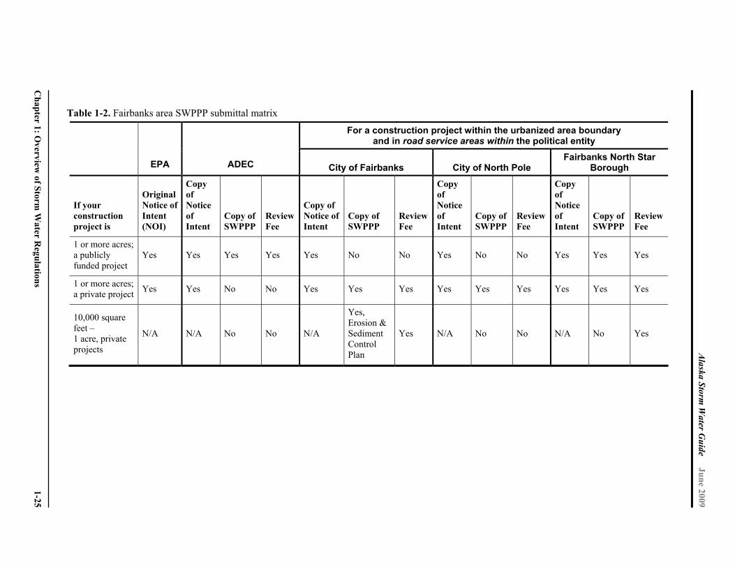
Alaska Storm
Water G
uide June 2009
Chapter 1: O
verview of Storm
Water R
egulations 1-25
Table 1-2. Fairbanks area SWPPP submittal matrix
For a construction project within the urbanized area boundary and in road service areas within the political entity
EPA ADEC City of Fairbanks City of North Pole Fairbanks North Star
Borough
If your construction project is
Original Notice of Intent (NOI)
Copy of Notice of Intent
Copy of SWPPP
Review Fee
Copy of Notice of Intent
Copy of SWPPP
Review Fee
Copy of Notice of Intent
Copy of SWPPP
Review Fee
Copy of Notice of Intent
Copy of SWPPP
Review Fee
1 or more acres; a publicly funded project
Yes Yes Yes Yes Yes No No Yes No No Yes Yes Yes
1 or more acres; a private project Yes Yes No No Yes Yes Yes Yes Yes Yes Yes Yes Yes
10,000 square feet – 1 acre, private projects
N/A N/A No No N/A
Yes, Erosion & Sediment Control Plan
Yes N/A No No N/A No Yes

Alaska Storm Water Guide June 2009
1-26 Chapter 1: Overview of Storm Water Regulations
1.3.3 Fairbanks North Star Borough
The Fairbanks North Star Borough has a separate permit, Permit Number AKS-053414. The
permit is at the Web Link 17 in Appendix A.
1.3.4 Other Local Authorities
Note that local governments in Alaska can have storm water ordinances without MS4
authority. For the current list, see the Alaska DCED Web site at Link 18 in Appendix A.
1.3.5 Land Development Considerations for Storm Water Management
Whether through ordinances or incentive-based approaches, many local jurisdictions are
beginning to apply better site design and LID techniques to all development and
redevelopment. These techniques are most effective when implemented as part of a
broader objective to reducing storm water runoff volumes and peak flows, increasing
groundwater recharge, and increasing the preservation of undisturbed areas. To minimize
the effects that new development and redevelopment projects can have on surface waters,
some of or all following practices should be considered where they are not in conflict with
land use compatibility objectives:
Minimize the amount of impervious surface created
Locate buildings on sites to minimize impervious cover associated with driveways and parking areas and to encourage tree preservation
Where feasible, convey drainage from impervious areas into pervious areas
Encourage cluster development when designed to maximize protection of ecologically valuable land
Encourage the preservation of wooded areas and steep slopes adjacent to stream valleys or other sensitive waters
1.4 Water Quality
1.4.1 Standards and Criteria
Water quality standards are the foundation of the water quality-based control program
mandated by the CWA. Alaska’s water quality standards are described in 18 AAC 70 Water
Quality Standards. Water quality standards define the goals for a waterbody by designating
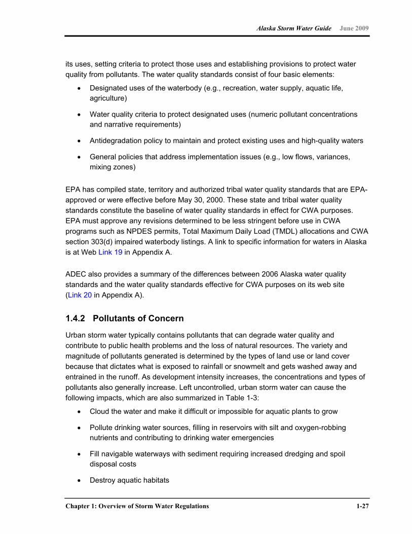
Alaska Storm Water Guide June 2009
Chapter 1: Overview of Storm Water Regulations 1-27
its uses, setting criteria to protect those uses and establishing provisions to protect water
quality from pollutants. The water quality standards consist of four basic elements:
Designated uses of the waterbody (e.g., recreation, water supply, aquatic life, agriculture)
Water quality criteria to protect designated uses (numeric pollutant concentrations and narrative requirements)
Antidegradation policy to maintain and protect existing uses and high-quality waters
General policies that address implementation issues (e.g., low flows, variances, mixing zones)
EPA has compiled state, territory and authorized tribal water quality standards that are EPA-
approved or were effective before May 30, 2000. These state and tribal water quality
standards constitute the baseline of water quality standards in effect for CWA purposes.
EPA must approve any revisions determined to be less stringent before use in CWA
programs such as NPDES permits, Total Maximum Daily Load (TMDL) allocations and CWA
section 303(d) impaired waterbody listings. A link to specific information for waters in Alaska
is at Web Link 19 in Appendix A.
ADEC also provides a summary of the differences between 2006 Alaska water quality
standards and the water quality standards effective for CWA purposes on its web site
(Link 20 in Appendix A).
1.4.2 Pollutants of Concern
Urban storm water typically contains pollutants that can degrade water quality and
contribute to public health problems and the loss of natural resources. The variety and
magnitude of pollutants generated is determined by the types of land use or land cover
because that dictates what is exposed to rainfall or snowmelt and gets washed away and
entrained in the runoff. As development intensity increases, the concentrations and types of
pollutants also generally increase. Left uncontrolled, urban storm water can cause the
following impacts, which are also summarized in Table 1-3:
Cloud the water and make it difficult or impossible for aquatic plants to grow
Pollute drinking water sources, filling in reservoirs with silt and oxygen-robbing nutrients and contributing to drinking water emergencies
Fill navigable waterways with sediment requiring increased dredging and spoil disposal costs
Destroy aquatic habitats
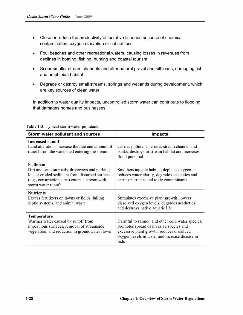
Alaska Storm Water Guide June 2009
1-28 Chapter 1: Overview of Storm Water Regulations
Close or reduce the productivity of lucrative fisheries because of chemical contamination, oxygen starvation or habitat loss
Foul beaches and other recreational waters, causing losses in revenues from declines in boating, fishing, hunting and coastal tourism
Scour smaller stream channels and alter natural gravel and silt loads, damaging fish and amphibian habitat
Degrade or destroy small streams, springs and wetlands during development, which are key sources of clean water
In addition to water quality impacts, uncontrolled storm water can contribute to flooding that damages homes and businesses.
Table 1-3. Typical storm water pollutants
Storm water pollutant and sources Impacts Increased runoff Land alterations increase the rate and amount of runoff from the watershed entering the stream.
Carries pollutants, erodes stream channel and banks, destroys in-stream habitat and increases flood potential
Sediment Dirt and sand on roads, driveways and parking lots or eroded sediment from disturbed surfaces (e.g., construction sites) enters a stream with storm water runoff.
Smothers aquatic habitat, depletes oxygen, reduces water clarity, degrades aesthetics and carries nutrients and toxic contaminants
Nutrients Excess fertilizers on lawns or fields, failing septic systems, and animal waste
Stimulates excessive plant growth, lowers dissolved oxygen levels, degrades aesthetics and destroys native aquatic life
Temperature Warmer water caused by runoff from impervious surfaces, removal of streamside vegetation, and reduction in groundwater flows
Harmful to salmon and other cold water species, promotes spread of invasive species and excessive plant growth, reduces dissolved oxygen levels in water and increase disease in fish.
Alaska Storm Water Guide June 2009
Chapter 1: Overview of Storm Water Regulations 1-29
Table 1-3. (continued)
Storm water pollutant and sources Impacts Bacteria Potentially pathogenic microscopic organisms in failing septic systems, sewer overflows, and animal (including pet) waste
Harmful to humans; untreated waste can cause numerous diseases.
Toxic contaminants/heavy metals Heavy metals such as mercury, cleaning compounds, pesticides and herbicides, industrial by-products such as dioxin, and vehicle leakage of oil, gas, and such.
Harmful to humans and aquatic life at fairly low levels; many resist break down and some accumulate in fish and other animal tissues (including human), and can lead to mutations, disease or cancer
Source: Adapted from Lake Superior Duluth Streams Web site (see Link 21 in Appendix A) (Duluth Streams, 2008)
Sediments/Solids Harmful effects: The accumulation of sediments and solids in water has significant negative
effect on the environment. These negative effects include the following:
A decrease in visibility and increase in turbidity for aquatic organisms, making it difficult for these organisms to capture prey
A decrease in light availability for photosynthetic organisms
Clogging of gills in fish and aquatic species
Reduction in fish spawning and general survival
Increase in the transportation of heavy metals, phosphorous and other pollutants through waterways as they attach to the sediment particles and harm water quality
Common sources of sediments and solids include the following:
Sand/gravel storage
Construction sites
Unpaved areas
Agriculture/livestock uses
Inadequate snow storage
Alaska Storm Water Guide June 2009
1-30 Chapter 1: Overview of Storm Water Regulations
Nutrients Harmful effects: Excess nitrogen and phosphorus promote toxic and nontoxic algal blooms,
which harm aquatic life by depleting the amount of oxygen in the water and by decreasing
light penetration for photosynthetic organisms, which can promote unwanted weed growth.
When algae die, they sink to the bottom and decompose in a process that removes oxygen
from the water. Fish and other aquatic organisms cannot exist in water with low dissolved
oxygen levels.
Common sources
Decaying vegetation
Organic matter
Treated wastewater
Biodegradable detergents
Animal wastes
Fertilizers
Metals Harmful effects: Metals have toxic effects on aquatic plants and animals and can
bioaccumulate in aquatic species, such as mussels, which can then have a dangerous
impact all the way through the food chain.
Trace metals, such as arsenic, copper, cyanide, mercury, nickel, and lead can come from air emissions from far away factories. These metals are toxic to aquatic life and accumulate in the sediments of streams, lakes, and estuaries as well as in fish tissue. These metals may come from pesticides, industrial waste discharges, solid waste landfill leachate, agricultural waste, or corroding metal pipes and storage tanks.
Common sources
Cadmium: burning fossil fuels, paint, batteries and electroplating
Chromium: air-conditioning coolants, timber treating works, leather tanning works and electroplating
Copper: vehicle brake pads, copper plumbing, irrigation water and pesticides
Zinc: vehicle tires, motor oils, galvanizing works, corrosion from galvanized iron
Lead: mainly car exhausts and engines
Arsenic: brake linings, fluid leaks and vehicle emissions
Alaska Storm Water Guide June 2009
Chapter 1: Overview of Storm Water Regulations 1-31
Pathogenic Bacteria Harmful effects: The accumulation of bacteria from wastes poses a serious threat to the
environment and to public health, especially for waterways where contact recreational
activities take place. From storm water, these bacteria make their way into streams and
lakes, which can cause biochemical oxygen demand (BOD) and depleted oxygen
concentrations, leading to closure of shellfish beds and swimming beaches.
Common sources
Human or animal wastes
Sediments from sources that have previously been contaminated by bacteria
Fertilizers derived from animal wastes
pH Harmful effects: Indicates an altered chemical balance in the water column, which can put
certain aquatic plants and animals at risk.
Common sources
Metal plating
Printing/graphic industries
Cement/concrete production
Wash waters
Groundwater (possibly also from heating, ventilation and air conditioning condensate)
Biochemical Oxygen Demand (BOD), Trace Organics and Litter Harmful effects: When organic matter is broken down by bacteria, it exerts oxygen demand.
Organic matter, such as leaves, grass and tree branches affect water quality because as it
decomposes, it consumes oxygen in the water. Reduced oxygen has a detrimental effect on
aquatic life, including fish, insects and plants. Trash (inorganic litter, including plastic debris)
produces an obvious visual pollution that can physically damage aquatic animals and fish
and can release substances poisonous to natural systems as it breaks down. Washed into
waterbodies, litter can choke, suffocate or disable aquatic life, including ducks, fish and
birds. Blocked culverts increase difficulty of fish passage.
Alaska Storm Water Guide June 2009
1-32 Chapter 1: Overview of Storm Water Regulations
Common sources
Litter (packaging/trash/garbage/debris)—plastic bags, six-pack rings, bottles, cigarette butts and such
Leaves, vegetation and yard waste
Deicing chemicals
1.4.3 Additional Water Quality Considerations
Antidegradation. The CWA requires states to develop an antidegradation policy
implementation plan. In 1996 Alaska adopted its antidegradation policy into the Water
Quality Standards (18 AAC 70). The basic purpose of the antidegradation policy is to
maintain and protect existing water quality. Many waterbodies have natural water quality
that is better than the criteria set by the Water Quality Standards at 18 AAC 70. In such
cases, a wastewater discharge might meet water quality standards but still cause some
degradation of the waterbody. The antidegradation policy sets requirements that a discharge
must meet to justify lowering the existing water quality. The CWA requires that the
implementation plan specify the procedures and criteria used to determine the following:
When waters are degraded by discharges or NPS pollution
Whether there are cost-effective alternatives to the new or increased discharge
What social and economic benefit to the state would be necessary to justify any degradation
The implementation plan must also have procedures for nominating and designating
Outstanding National Resource Waters, which allows special protections for such
designated waterbodies. ADEC plans to develop implementation guidance that will provide
specific information and procedures necessary to ensure that the requirements of Alaska’s
antidegradation policy are met consistently and predictably. This guidance will be developed
in collaboration with other state and federal agencies and public input. A Web link, Link 22,
to additional information is in Appendix A.
Impaired Waterbodies. Section 303 of the CWA establishes the water quality standards
and TMDL program. Section 303(d) requires states to identify waters that do not meet
applicable water quality standards with technology-based controls alone. Waters affected by
thermal discharges must be identified. After identifying and priority ranking their water
quality-limited waters, states must develop TMDLs at a level necessary to achieve the
applicable water quality standards. TMDLs are a calculation of the maximum amount of a
pollutant that a waterbody can receive and still meet water quality standards, and an
allocation of that amount to the pollutants’ sources. Storm water is a common transport

Alaska Storm Water Guide June 2009
Chapter 1: Overview of Storm Water Regulations 1-33
mechanism of pollutants to waterbodies. ADEC lists impaired waters requiring TMDLs in
Category 5 of the Alaska Integrated Water Quality Monitoring and Assessment Report,
which is known as the 303(d) list.
A TMDL is required for a polluted waterbody to be removed from the 303(d) list of impaired
waters. A waterbody can also be removed if there are assurances that pollution controls are
in place, or will be in place that will result in attainment of water quality standards. EPA must
approve TMDLs. TMDLs are implemented through BMPs for nonpoint sources of pollutants
and through NPDES permits for point sources of pollution. These waters are shown in
Category 4b of the Integrated Report. EPA approved TMDLs are available for viewing and
printing in PDF format from the Web, see Link 23 in Appendix A.
Anadromous fish habitat. Alaska Statute AS 16.05.871 (the Anadromous Fish Act)
requires that an individual or governmental agency provide prior notification and obtain
approval from the Alaska Department of Fish & Game (ADF&G), “to construct a hydraulic
project or use, divert, obstruct, pollute, or change the natural flow or bed” of a specified
anadromous waterbody or “to use wheeled, tracked, or excavating equipment or log-
dragging equipment in the bed” of a specified anadromous waterbody. The ADF&G Division
of Habitat is responsible for ensuring preservation of the state’s fish and wildlife resources
by protecting the habitat necessary for the organisms to complete their life cycles.
The Division of Habitat has specific statutory responsibility for protecting freshwater
anadromous fish habitat and for providing free passage for anadromous and resident fish in
freshwater waterbodies under the Fish Way Act (Alaska Statute AS 16.05.841). The
Division of Habitat fulfills this responsibility by writing Fish Habitat Permits for activities and
projects conducted by private individuals or other state or federal government agencies
below the ordinary high water boundary of fish streams. Habitat biologists in the Division of
Habitat conduct research and field surveys, review plans with permit applicants to help
ensure that projects do not adversely impact fish habitat and monitor projects for compliance
with permit standards.
In addition to permitting duties, the Division of Habitat coordinates with other agencies
during plan reviews to provide expertise for protecting both important fish and wildlife habitat
throughout the state. Examples of these reviews most relevant to storm water include
working with the state Division of Forestry to review timber harvest plans, working with the
Alaska Department of Natural Resources (DNR) Office of Project Management and
Permitting on major new projects and providing comments on projects under review for
consistency with the Alaska Coastal Management Program. The Division of Habitat also
works cooperatively within the ADF&G to maintain and revise the Catalog of Waters
Important for the Spawning, Rearing, or Migration of Anadromous Fishes, which lists
Alaska Storm Water Guide June 2009
1-34 Chapter 1: Overview of Storm Water Regulations
waterbodies that are known to be used by anadromous fish and gives these streams and
lakes legal protection as important fish habitat.
1.5 Enforcement and NPDES Primacy
EPA is the NPDES permitting authority for all NPDES storm water permits in Alaska until
October 31, 2009, after which ADEC assumes the responsibility to issue and enforce the
municipal, industrial and construction storm water permits. Substantial changes are not
anticipated to storm water permits during the transition because EPA has worked closely
with ADEC in developing the existing NPDES permits; ADEC has certified that EPA permits
will meet state water quality standards. ADEC also issues discharge permits under state
authority for discharges that EPA is not authorized to permit. As described above in the local
programs discussion, the Municipality of Anchorage conducts enforcement of dischargers to
its MS4. The City of Fairbanks, the City of North Pole and the Fairbanks North Star Borough
are developing ordinances that they will enforce through their MS4 storm water
management programs.
Section 402 of the CWA requires that all discharges to surface waters be permitted under
the NPDES permit program. The CWA intends for states to implement (to have primacy for)
the NPDES program with EPA acting in an oversight role. As of March 2009, 46 states have
primacy for the NPDES program. The four other states that do not have NPDES primacy are
Idaho, New Mexico, New Hampshire and Massachusetts.
Senate Bill 110, signed into law August 27, 2005, authorizes and directs ADEC to pursue
NPDES primacy from EPA. ADEC submitted an application for primacy to EPA in May 2008,
and EPA authorized ADEC to begin a phased approach to transfer primacy from EPA to
ADEC on October 31, 2008. NPDES primacy will allow Alaska to take over discharge
permitting authority including responsibility for issuing and monitoring compliance with the
permits. ADEC has requested responsibility for the following components of the NPDES
permit program:
NPDES Permitting, which includes developing, issuing, modifying and renewing the permits for all process wastewater from industrial facilities and municipal wastewater treatment plants that discharge to waters of the United States. This includes the permitting of storm water discharges from construction and industrial activities, as well storm water discharged by regulated MS4s. It also includes permitting discharges from federally owned facilities such as Department of Defense installations.
Alaska Storm Water Guide June 2009
Chapter 1: Overview of Storm Water Regulations 1-35
Pretreatment Program, which consists of regulating highly toxic discharges into sewerage systems.
Compliance and Enforcement, which includes monitoring compliance with permit terms and conditions and taking enforcement action when necessary.
The NPDES storm water program is anticipated to be transferred from EPA to ADEC on October 31, 2009. The storm water permits that are in effect at the time of transfer will become APDES permits with no changes to the EPA permits. As previously mentioned, local governments may also have authority under their specific charters to enact and enforce local storm water, pollution control, and erosion and sediment control regulations.

This page intentionally left blank

Alaska Storm Water Guide June 2009
Chapter 2: Storm Water Considerations for Alaska 2-1
Chapter 2 Storm Water Considerations for Alaska
2.0 Introduction
Alaska is a diverse environment with respect to the sensitivity of its streams to land
development, its range of climate, soils, terrain and development patterns, and how these
constrain and challenge designers to adapt storm water management tools developed at
lower latitudes. This chapter begins by reviewing why controlling storm water runoff is
important to protect water quality and stream health. Next, it describes the great diversity in
rainfall, snowfall, temperature and soils throughout the state, and describes five broad
climatic zones to guide storm water implementation. The next section describes how these
climatic and terrain factors influence local decisions to focus on managing rain water or
snowmelt, and briefly describes the key elements of each management approach.
The fourth section outlines the extreme factors in Alaska that constrain the use of storm
water practices developed in other regions of the world and indicates how these factors
influence the sizing, design and selection of storm water practices. The fifth section is a
reminder that Alaska is experiencing climate change and presents some suggestions on
adaptive engineering to ensure that storm water infrastructure can accommodate it. The
sixth section briefly discusses the topic of winter construction, which is a common condition
in parts of the state. The chapter concludes by outlining the special pollution prevention,
source control, and storm water treatment requirements for operations and activities
classified as storm water hotspots that are known to produce higher levels of runoff pollution
and merit greater controls.
2.1 Why Urban Storm Water Matters to Alaska Streams
Extensive research conducted at lower latitudes has shown that land development and,
more specifically impervious cover, have a strong influence on stream hydrology, water
quality, habitat and biodiversity (CWP 2003; Schuster et al. 2007; Pitt et al. 2004; Roy 2005;
Schueler et al. 2009). Impervious cover consists of hard surfaces created after

Alaska Storm Water Guide June 2009
2-2 Chapter 2: Storm Water Considerations for Alaska
development, such as rooftops, streets, sidewalks and parking lots. In general, stream
quality indicators degrade as more impervious cover is added to a watershed. Impervious
cover and compacted soils generate greater volumes of storm water runoff, which degrades
stream habitat. In addition, significant loads of sediment, nutrients, pathogens, metals and
other pollutants wash off impervious surfaces and are quickly delivered to streams. The
effect of declining water quality and degraded habitat generally lead to much lower
biodiversity in streams. A similar phenomenon has been observed for streams and
wetlands, lakes and near-shore coastal habitats (CWP 2003). In addition, pollutant washoff
can contaminate water supplies and reduce drinking water quality.
The limited but growing body of Alaskan research on impervious cover, storm water and
stream health generally reinforces this paradigm. Indeed, the research suggests that
Alaskan streams might be even more vulnerable to the effects of land development because
of the extreme climatic stressors found in the state. To date, most of the research has
focused on Anchorage and southeastern Alaska. Some key findings are outlined below.
Changes in Hydrology: Topographic relief is often extreme in Alaskan communities, and
the growth of impervious surfaces has produced major changes in stream hydrology. For
example, recent models have indicated that runoff volumes have increased three- to fivefold
in Anchorage watersheds from 1950 to 2000, and peak discharge rates have increased by a
factor of 5 to 10. Dry-weather stream baseflow has declined by an order of magnitude over
the same time frame because of lower groundwater recharge (MOA 2004).
Increased Pollutant Washoff: Recent monitoring studies have indicated that several storm
water pollutants are a significant water quality concern in urban watersheds in Alaska (MOA
2003; MOA 2004; Shannon and Wilson 2006; Ourso and Frenzel 2003). Such pollutants
include suspended sediment, chloride, pathogens such as fecal coliform bacteria, oil and
grease, trace metals—such as cadmium, zinc and lead—and trash and floatable debris.
Urban Stream Channel Erosion: Increased urban storm water flows appear to be greatly
increasing channel erosion and sediment delivery in Anchorage streams (MOA 2004), with a
consequent decline in channel condition, substrate habitat and sediment quality (Ourso and
Frenzel 2003). Other effects noted in urban streams include decreased slope, increases in
sediment size, width, depth and meander wavelength. These changes in stream habitat
quality are particularly noteworthy given their importance to sustaining anadromous fish
runs, such as salmon. Research on salmon streams in the Pacific Northwest has shown a
strong link between increasing urbanization and the decline of local salmon runs (Morley
and Karr 2002).
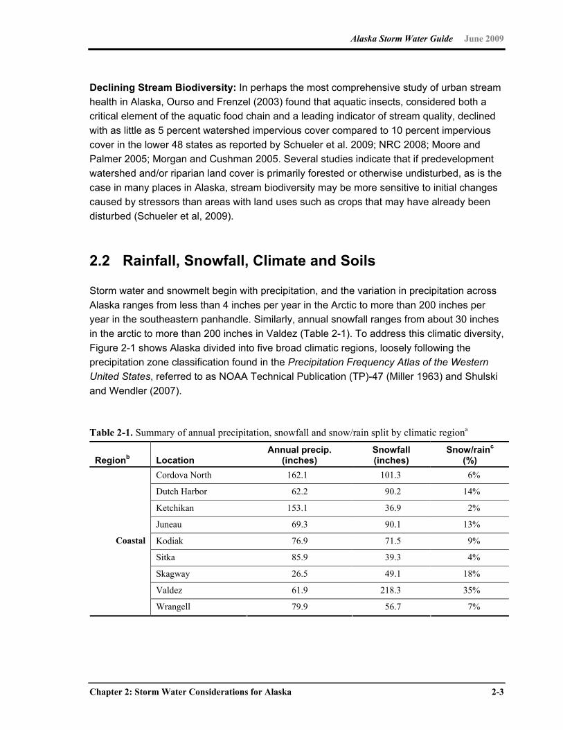
Alaska Storm Water Guide June 2009
Chapter 2: Storm Water Considerations for Alaska 2-3
Declining Stream Biodiversity: In perhaps the most comprehensive study of urban stream
health in Alaska, Ourso and Frenzel (2003) found that aquatic insects, considered both a
critical element of the aquatic food chain and a leading indicator of stream quality, declined
with as little as 5 percent watershed impervious cover compared to 10 percent impervious
cover in the lower 48 states as reported by Schueler et al. 2009; NRC 2008; Moore and
Palmer 2005; Morgan and Cushman 2005. Several studies indicate that if predevelopment
watershed and/or riparian land cover is primarily forested or otherwise undisturbed, as is the
case in many places in Alaska, stream biodiversity may be more sensitive to initial changes
caused by stressors than areas with land uses such as crops that may have already been
disturbed (Schueler et al, 2009).
2.2 Rainfall, Snowfall, Climate and Soils
Storm water and snowmelt begin with precipitation, and the variation in precipitation across
Alaska ranges from less than 4 inches per year in the Arctic to more than 200 inches per
year in the southeastern panhandle. Similarly, annual snowfall ranges from about 30 inches
in the arctic to more than 200 inches in Valdez (Table 2-1). To address this climatic diversity,
Figure 2-1 shows Alaska divided into five broad climatic regions, loosely following the
precipitation zone classification found in the Precipitation Frequency Atlas of the Western
United States, referred to as NOAA Technical Publication (TP)-47 (Miller 1963) and Shulski
and Wendler (2007).
Table 2-1. Summary of annual precipitation, snowfall and snow/rain split by climatic regiona
Regionb Location Annual precip.
(inches) Snowfall (inches)
Snow/rainc
(%) Cordova North 162.1 101.3 6%
Dutch Harbor 62.2 90.2 14%
Ketchikan 153.1 36.9 2%
Juneau 69.3 90.1 13%
Kodiak 76.9 71.5 9%
Sitka 85.9 39.3 4%
Skagway 26.5 49.1 18%
Valdez 61.9 218.3 35%
Coastal
Wrangell 79.9 56.7 7%

Alaska Storm Water Guide June 2009
2-4 Chapter 2: Storm Water Considerations for Alaska
Table 2-1. (continued)
Regionb Location Annual precip.
(inches) Snowfall (inches)
Snow/rainc (%)
Anchorage 15.9 70.2 44%
Homer 24.5 54.9 22%
Matanuska Valley 16.0 60.7 37% Southcentral
Kenai 18.9 61.2 32%
Bethel 17.0 54.3 32%
Dillingham 25.5 82.9 32% Western
Nome 16.1 60.8 38%
Big Delta 11.4 43.8 38%
Fairbanks 10.5 66.4 63%
Fort Yukon 6.6 41.9 63% Interior
Galena 13.2 63.4 48%
Kotezbue 9.6 52.4 53%
Prudhoe Bay 4.3 33.1 77%
Umiat 5.6 55.2 61% Arctic
Barrow 4.0 29.0 74%
Note: There are significant precipitation variations within each region, so the site-specific information could result in differing feasibility determinations; practitioners should use the best available data.
a. Source of data are long-term climate records in WRRC (2007) and Shulski and Wendler (2007) b. The Coastal Region includes TP-47 zones 1, 2 and 6; the Southcentral Region is TP-47 zone 4 ; The Western
Region includes TP-47 zones 5 and 8; the Interior Region includes TP-47 zones 3 and 7; and the Arctic region is TP-47 zone 9
c. The ratio was derived assuming a 10:1 water equivalency for snowfall depth
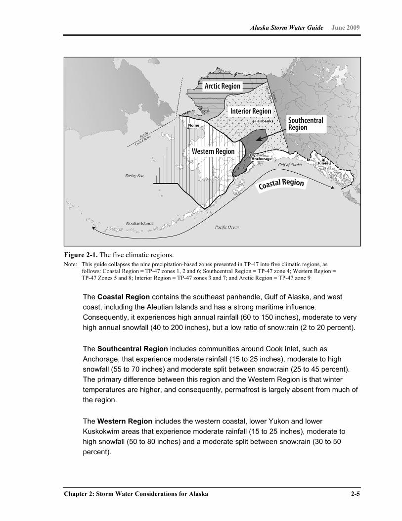
Alaska Storm Water Guide June 2009
Chapter 2: Storm Water Considerations for Alaska 2-5
Figure 2-1. The five climatic regions. Note: This guide collapses the nine precipitation-based zones presented in TP-47 into five climatic regions, as
follows: Coastal Region = TP-47 zones 1, 2 and 6; Southcentral Region = TP-47 zone 4; Western Region = TP-47 Zones 5 and 8; Interior Region = TP-47 zones 3 and 7; and Arctic Region = TP-47 zone 9
The Coastal Region contains the southeast panhandle, Gulf of Alaska, and west
coast, including the Aleutian Islands and has a strong maritime influence.
Consequently, it experiences high annual rainfall (60 to 150 inches), moderate to very
high annual snowfall (40 to 200 inches), but a low ratio of snow:rain (2 to 20 percent).
The Southcentral Region includes communities around Cook Inlet, such as
Anchorage, that experience moderate rainfall (15 to 25 inches), moderate to high
snowfall (55 to 70 inches) and moderate split between snow:rain (25 to 45 percent).
The primary difference between this region and the Western Region is that winter
temperatures are higher, and consequently, permafrost is largely absent from much of
the region.
The Western Region includes the western coastal, lower Yukon and lower
Kuskokwim areas that experience moderate rainfall (15 to 25 inches), moderate to
high snowfall (50 to 80 inches) and a moderate split between snow:rain (30 to 50
percent).
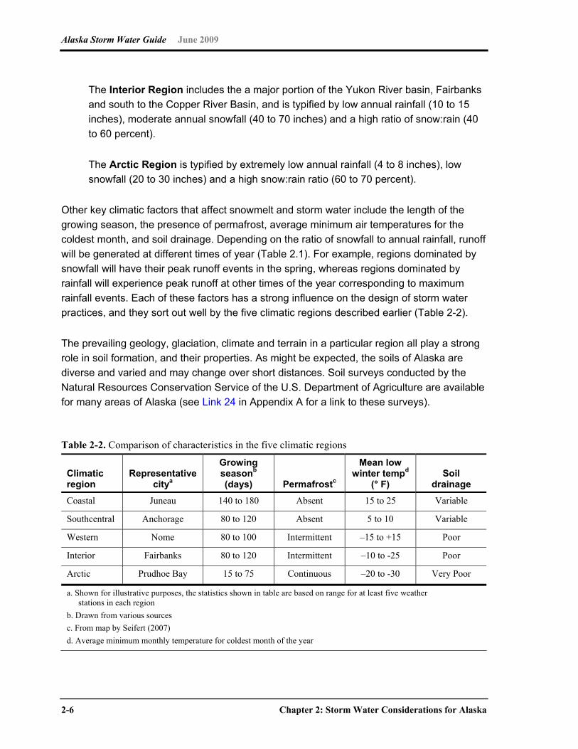
Alaska Storm Water Guide June 2009
2-6 Chapter 2: Storm Water Considerations for Alaska
The Interior Region includes the a major portion of the Yukon River basin, Fairbanks
and south to the Copper River Basin, and is typified by low annual rainfall (10 to 15
inches), moderate annual snowfall (40 to 70 inches) and a high ratio of snow:rain (40
to 60 percent).
The Arctic Region is typified by extremely low annual rainfall (4 to 8 inches), low
snowfall (20 to 30 inches) and a high snow:rain ratio (60 to 70 percent).
Other key climatic factors that affect snowmelt and storm water include the length of the
growing season, the presence of permafrost, average minimum air temperatures for the
coldest month, and soil drainage. Depending on the ratio of snowfall to annual rainfall, runoff
will be generated at different times of year (Table 2.1). For example, regions dominated by
snowfall will have their peak runoff events in the spring, whereas regions dominated by
rainfall will experience peak runoff at other times of the year corresponding to maximum
rainfall events. Each of these factors has a strong influence on the design of storm water
practices, and they sort out well by the five climatic regions described earlier (Table 2-2).
The prevailing geology, glaciation, climate and terrain in a particular region all play a strong
role in soil formation, and their properties. As might be expected, the soils of Alaska are
diverse and varied and may change over short distances. Soil surveys conducted by the
Natural Resources Conservation Service of the U.S. Department of Agriculture are available
for many areas of Alaska (see Link 24 in Appendix A for a link to these surveys).
Table 2-2. Comparison of characteristics in the five climatic regions
Climatic region
Representative citya
Growing seasonb (days) Permafrostc
Mean low winter tempd
(° F) Soil
drainage Coastal Juneau 140 to 180 Absent 15 to 25 Variable
Southcentral Anchorage 80 to 120 Absent 5 to 10 Variable
Western Nome 80 to 100 Intermittent –15 to +15 Poor
Interior Fairbanks 80 to 120 Intermittent –10 to -25 Poor
Arctic Prudhoe Bay 15 to 75 Continuous –20 to -30 Very Poor
a. Shown for illustrative purposes, the statistics shown in table are based on range for at least five weather stations in each region
b. Drawn from various sources c. From map by Seifert (2007) d. Average minimum monthly temperature for coldest month of the year

Alaska Storm Water Guide June 2009
Chapter 2: Storm Water Considerations for Alaska 2-7
The Alaska Department of Natural Resources Division of Geological and Geophysical
Surveys has mapped the engineering geology for many areas of Alaska (for more
information, see Link 25 in Appendix A). Table 2-3 presents a general overview of soils with
the five climatic regions of the state, following Gallant et al. (1995).
Table 2-3. General soil conditions in the five climate regions
Coastal Region (Southeast, Gulf of Alaska, Aleutians). Soils near the mountains tend to be gravelly or sandy moraine deposits. Soils in poorly drained depressions are filled with organic material and tend to be saturated. Debris flows can occur in shallow soils on slopes of 35 to 60 degrees where the underlying bedrock surfaces are often glacially smoothed. Permafrost is absent in coastal areas.
Southcentral Region (Cook Inlet) The region tends to be covered by glacial deposits covered with low moraines and interspersed with many lakes, bogs and broad outwash plains. There are areas where the surface soil layers are formed by wind blown loess from the floodplains of glacial rivers and from volcanic ash blown from nearby volcanoes. Subsurface soil layers tend to be formed predominantly of glacial deposits ranging from gravelly clay loam to very gravelly sandy loam. Alluvial terraces and outwash plains tend to be water-worked, very gravelly sand. Soils in depressions tend to be bogs consisting of peat. Permafrost is substantially absent.
Western Region (Bristol Bay coastal areas and western interior) Most soils are formed by volcanic ash deposits of various thicknesses and are underlain by gravelly glacial till, outwash deposits or silty alluvium. Coastal plain soils other than the Yukon River delta can be formed in gravelly alluvium. Low-lying areas can be filled with organic material. Permafrost is discontinuous throughout the region.
Interior Region (Upper Yukon and Copper River basins) Many of the upland soils were formed by silty, loess, or colluvial material. Some other upland area soils were formed by stone and gravel weathered from local rock. Lowland soils were formed in silty alluvium and loess derived from floodplains of large rivers. Soils are generally shallow, often overlying ice-rich permafrost and tend to be poorly drained. Those soils with permafrost are very susceptible to alteration upon disturbance of the organic vegetation. Permafrost can be prevalent on north-facing slopes and nearly absent on south-facing slopes. Soils in the Copper River basin tend to be poorly drained and underlain with permafrost. Organic soils typically fill depressions, while well-drained soils typically cover upland areas.
Arctic Region (Northwest and Northslope) The principal soils of the Arctic Coastal plain and broad valley bottoms tend to be poorly drained, developed under a thick layer of vegetation and are underlain with thick permafrost. They are interspersed with many lakes. The dominant soils in the valleys and long slopes of the Arctic foothills are silty or loamy colluvial sediments. The hills and ridges are mostly composed of very gravelly material eroded from sedimentary rock.
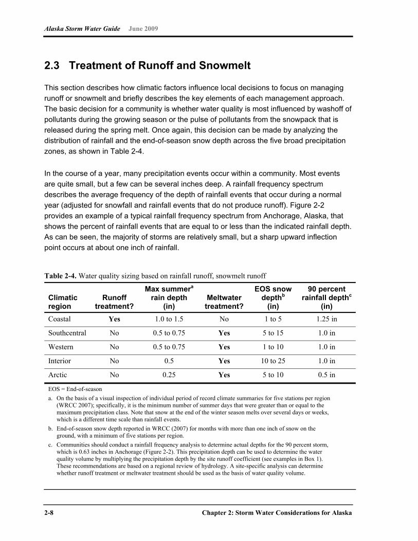
Alaska Storm Water Guide June 2009
2-8 Chapter 2: Storm Water Considerations for Alaska
2.3 Treatment of Runoff and Snowmelt
This section describes how climatic factors influence local decisions to focus on managing
runoff or snowmelt and briefly describes the key elements of each management approach.
The basic decision for a community is whether water quality is most influenced by washoff of
pollutants during the growing season or the pulse of pollutants from the snowpack that is
released during the spring melt. Once again, this decision can be made by analyzing the
distribution of rainfall and the end-of-season snow depth across the five broad precipitation
zones, as shown in Table 2-4.
In the course of a year, many precipitation events occur within a community. Most events
are quite small, but a few can be several inches deep. A rainfall frequency spectrum
describes the average frequency of the depth of rainfall events that occur during a normal
year (adjusted for snowfall and rainfall events that do not produce runoff). Figure 2-2
provides an example of a typical rainfall frequency spectrum from Anchorage, Alaska, that
shows the percent of rainfall events that are equal to or less than the indicated rainfall depth.
As can be seen, the majority of storms are relatively small, but a sharp upward inflection
point occurs at about one inch of rainfall.
Table 2-4. Water quality sizing based on rainfall runoff, snowmelt runoff
Climatic region
Runoff treatment?
Max summera rain depth
(in) Meltwater treatment?
EOS snow depthb
(in)
90 percent rainfall depthc
(in) Coastal Yes 1.0 to 1.5 No 1 to 5 1.25 in
Southcentral No 0.5 to 0.75 Yes 5 to 15 1.0 in
Western No 0.5 to 0.75 Yes 1 to 10 1.0 in
Interior No 0.5 Yes 10 to 25 1.0 in
Arctic No 0.25 Yes 5 to 10 0.5 in
EOS = End-of-season a. On the basis of a visual inspection of individual period of record climate summaries for five stations per region
(WRCC 2007); specifically, it is the minimum number of summer days that were greater than or equal to the maximum precipitation class. Note that snow at the end of the winter season melts over several days or weeks, which is a different time scale than rainfall events.
b. End-of-season snow depth reported in WRCC (2007) for months with more than one inch of snow on the ground, with a minimum of five stations per region.
c. Communities should conduct a rainfall frequency analysis to determine actual depths for the 90 percent storm, which is 0.63 inches in Anchorage (Figure 2-2). This precipitation depth can be used to determine the water quality volume by multiplying the precipitation depth by the site runoff coefficient (see examples in Box 1). These recommendations are based on a regional review of hydrology. A site-specific analysis can determine whether runoff treatment or meltwater treatment should be used as the basis of water quality volume.
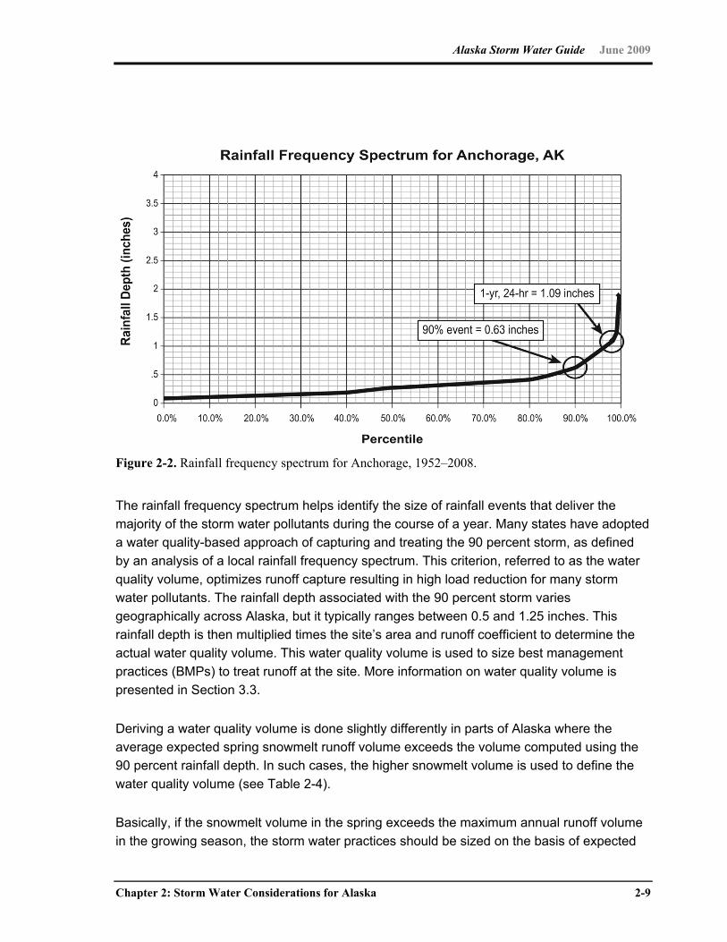
Alaska Storm Water Guide June 2009
Chapter 2: Storm Water Considerations for Alaska 2-9
Figure 2-2. Rainfall frequency spectrum for Anchorage, 1952–2008.
The rainfall frequency spectrum helps identify the size of rainfall events that deliver the
majority of the storm water pollutants during the course of a year. Many states have adopted
a water quality-based approach of capturing and treating the 90 percent storm, as defined
by an analysis of a local rainfall frequency spectrum. This criterion, referred to as the water
quality volume, optimizes runoff capture resulting in high load reduction for many storm
water pollutants. The rainfall depth associated with the 90 percent storm varies
geographically across Alaska, but it typically ranges between 0.5 and 1.25 inches. This
rainfall depth is then multiplied times the site’s area and runoff coefficient to determine the
actual water quality volume. This water quality volume is used to size best management
practices (BMPs) to treat runoff at the site. More information on water quality volume is
presented in Section 3.3.
Deriving a water quality volume is done slightly differently in parts of Alaska where the
average expected spring snowmelt runoff volume exceeds the volume computed using the
90 percent rainfall depth. In such cases, the higher snowmelt volume is used to define the
water quality volume (see Table 2-4).
Basically, if the snowmelt volume in the spring exceeds the maximum annual runoff volume
in the growing season, the storm water practices should be sized on the basis of expected
Alaska Storm Water Guide June 2009
2-10 Chapter 2: Storm Water Considerations for Alaska
snowmelt volume for each climatic region (Coastal, Southcentral, Western, Interior and
Arctic). Conversely, if runoff from the maximum annual rain storms exceeds the spring
snowmelt volume, the storm water practices should be sized on the basis of the expected
runoff volume (e.g., Coastal Region). Although the specific techniques to derive the local
water quality storm event are described in Chapter 3, Table 2-4 presents a range of
expected depths for the water quality volume for each climatic region.
Additional guidance on how Alaskan communities can determine whether their water quality
volume should be based on summer rainfall depths or end–of-season snowpack depth can
be found in Box 1. The box also provides the basic equation for determining water quality
volume at individual development sites.
The basic elements of the runoff and snowmelt approach to managing storm water are
described in Tables 2-5 and 2-6, respectively. The two approaches are not meant to be
mutually exclusive; indeed, the basic steps outlined for site development for runoff
management also apply to communities that need to manage snowmelt. The main
difference is the water quality volume needed for storm water practices used and how they
are operated and maintained during each season the year.
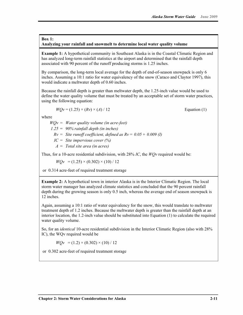
Alaska Storm Water Guide June 2009
Chapter 2: Storm Water Considerations for Alaska 2-11
Box 1: Analyzing your rainfall and snowmelt to determine local water quality volume
Example 1: A hypothetical community in Southeast Alaska is in the Coastal Climatic Region and has analyzed long-term rainfall statistics at the airport and determined that the rainfall depth associated with 90 percent of the runoff producing storms is 1.25 inches.
By comparison, the long-term local average for the depth of end-of-season snowpack is only 6 inches. Assuming a 10:1 ratio for water equivalency of the snow (Caraco and Claytor 1997), this would indicate a meltwater depth of 0.60 inches.
Because the rainfall depth is greater than meltwater depth, the 1.25-inch value would be used to define the water quality volume that must be treated by an acceptable set of storm water practices, using the following equation:
WQv = (1.25) × (Rv) × (A) / 12 Equation (1)
where WQv = Water quality volume (in acre-feet) 1.25 = 90% rainfall depth (in inches) Rv = Site runoff coefficient, defined as Rv = 0.05 + 0.009 (I) IC = Site impervious cover (%) A = Total site area (in acres)
Thus, for a 10-acre residential subdivision, with 28% IC, the WQv required would be:
WQv = (1.25) × (0.302) × (10) / 12
or 0.314 acre-feet of required treatment storage
Example 2: A hypothetical town in interior Alaska is in the Interior Climatic Region. The local storm water manager has analyzed climate statistics and concluded that the 90 percent rainfall depth during the growing season is only 0.5 inch, whereas the average end of season snowpack is 12 inches.
Again, assuming a 10:1 ratio of water equivalency for the snow, this would translate to meltwater treatment depth of 1.2 inches. Because the meltwater depth is greater than the rainfall depth at an interior location, the 1.2-inch value should be substituted into Equation (1) to calculate the required water quality volume.
So, for an identical 10-acre residential subdivision in the Interior Climatic Region (also with 28% IC), the WQv required would be
WQv = (1.2) × (0.302) × (10) / 12
or 0.302 acre-feet of required treatment storage
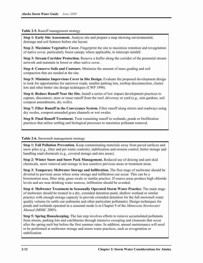
Alaska Storm Water Guide June 2009
2-12 Chapter 2: Storm Water Considerations for Alaska
Table 2-5. Runoff management strategy
Step 1: Early Site Assessment. Analyze site and prepare a map showing environmental, drainage and soil features before site layout.
Step 2: Maximize Vegetative Cover. Fingerprint the site to maximize retention and revegetation of native cover, particularly forest canopy where applicable, to intercept rainfall.
Step 3: Stream Corridor Protection. Reserve a buffer along the corridor of the perennial stream network and maintain in forest or other native cover.
Step 4: Conserve Soils and Contours. Minimize the amount of mass grading and soil compaction that are needed at the site.
Step 5: Minimize Impervious Cover in Site Design. Evaluate the proposed development design to look for opportunities for narrower roads, smaller parking lots, rooftop disconnection, cluster lots and other better site design techniques (CWP 1998).
Step 6: Reduce Runoff Near the Site. Install a series of low impact development practices to capture, disconnect, store or reuse runoff from the roof, driveway or yard (e.g., rain gardens, soil compost amendments, dry wells).
Step 7: Filter Runoff in the Conveyance System. Filter runoff along streets and roadways using dry swales, compost-amended grass channels or wet swales.
Step 8: Final Runoff Treatment. Treat remaining runoff in wetlands, ponds or biofiltration practices that utilize settling and biological processes to maximize pollutant removal.
Table 2-6. Snowmelt management strategy
Step 1: Fall Pollution Prevention. Keep contaminating materials away from paved surfaces and snow piles (e.g., litter and pet waste controls), stabilization and erosion control, better storage and handling road chemicals (e.g., covered storage and mix areas).
Step 2: Winter Snow and Snow Pack Management. Reduced use of deicing and anti-skid chemicals, snow removal and storage in less sensitive pervious areas or treatment areas.
Step 3: Temporary Meltwater Storage and Infiltration. The first stage of meltwater should be diverted to pervious areas where some storage and infiltration can occur. This can be a bioretention area, filter strip, grass swale or similar practice. If source areas produce high chloride levels and are near drinking water sources, infiltration should be avoided.
Step 4: Meltwater Treatment in Seasonally Operated Storm Water Practice. The main stage of meltwater should be treated in a dry, extended detention pond, shallow wetland or similar practice with enough storage capacity to provide extended detention for the full snowmelt water quality volume (to settle out sediments and other particulate pollutants). Design techniques for ponds and wetlands operated in a seasonal mode is in Chapter 9 of the Minnesota Stormwater Manual (MSSC 2005).
Step 5: Spring Housekeeping. The last step involves efforts to remove accumulated pollutants from streets, parking lots and catchbasins through intensive sweeping and cleanouts that occur after the spring melt but before the first summer rains. In addition, annual maintenance will need to be performed at meltwater storage and storm water practices, such as revegetation or stabilization.
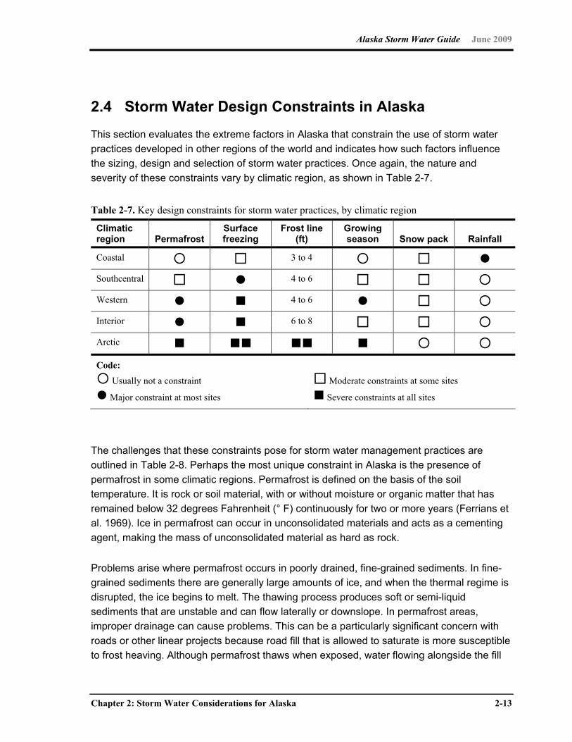
Alaska Storm Water Guide June 2009
Chapter 2: Storm Water Considerations for Alaska 2-13
2.4 Storm Water Design Constraints in Alaska
This section evaluates the extreme factors in Alaska that constrain the use of storm water
practices developed in other regions of the world and indicates how such factors influence
the sizing, design and selection of storm water practices. Once again, the nature and
severity of these constraints vary by climatic region, as shown in Table 2-7.
Table 2-7. Key design constraints for storm water practices, by climatic region
Climatic region Permafrost
Surface freezing
Frost line (ft)
Growing season Snow pack Rainfall
Coastal 3 to 4 Southcentral 4 to 6 Western 4 to 6 Interior 6 to 8 Arctic Code: Usually not a constraint
Major constraint at most sites
Moderate constraints at some sites
Severe constraints at all sites
The challenges that these constraints pose for storm water management practices are
outlined in Table 2-8. Perhaps the most unique constraint in Alaska is the presence of
permafrost in some climatic regions. Permafrost is defined on the basis of the soil
temperature. It is rock or soil material, with or without moisture or organic matter that has
remained below 32 degrees Fahrenheit (° F) continuously for two or more years (Ferrians et
al. 1969). Ice in permafrost can occur in unconsolidated materials and acts as a cementing
agent, making the mass of unconsolidated material as hard as rock.
Problems arise where permafrost occurs in poorly drained, fine-grained sediments. In fine-
grained sediments there are generally large amounts of ice, and when the thermal regime is
disrupted, the ice begins to melt. The thawing process produces soft or semi-liquid
sediments that are unstable and can flow laterally or downslope. In permafrost areas,
improper drainage can cause problems. This can be a particularly significant concern with
roads or other linear projects because road fill that is allowed to saturate is more susceptible
to frost heaving. Although permafrost thaws when exposed, water flowing alongside the fill
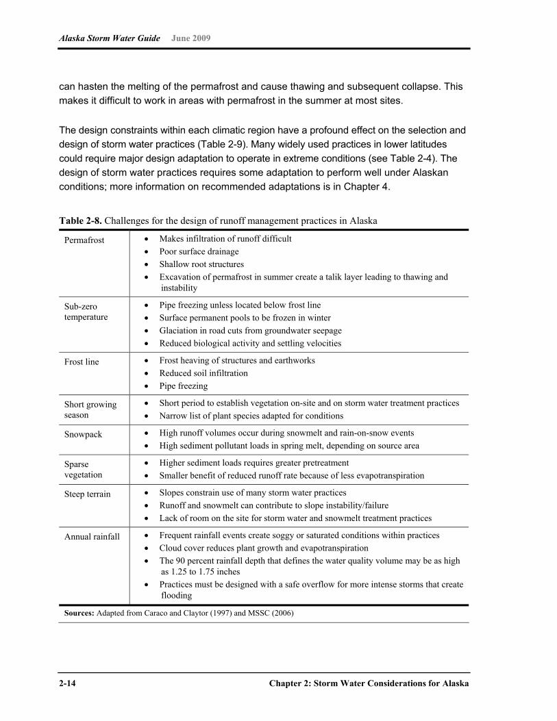
Alaska Storm Water Guide June 2009
2-14 Chapter 2: Storm Water Considerations for Alaska
can hasten the melting of the permafrost and cause thawing and subsequent collapse. This
makes it difficult to work in areas with permafrost in the summer at most sites.
The design constraints within each climatic region have a profound effect on the selection and
design of storm water practices (Table 2-9). Many widely used practices in lower latitudes
could require major design adaptation to operate in extreme conditions (see Table 2-4). The
design of storm water practices requires some adaptation to perform well under Alaskan
conditions; more information on recommended adaptations is in Chapter 4.
Table 2-8. Challenges for the design of runoff management practices in Alaska
Permafrost Makes infiltration of runoff difficult Poor surface drainage Shallow root structures Excavation of permafrost in summer create a talik layer leading to thawing and
instability
Sub-zero temperature
Pipe freezing unless located below frost line Surface permanent pools to be frozen in winter Glaciation in road cuts from groundwater seepage Reduced biological activity and settling velocities
Frost line Frost heaving of structures and earthworks Reduced soil infiltration Pipe freezing
Short growing season
Short period to establish vegetation on-site and on storm water treatment practices Narrow list of plant species adapted for conditions
Snowpack High runoff volumes occur during snowmelt and rain-on-snow events High sediment pollutant loads in spring melt, depending on source area
Sparse vegetation
Higher sediment loads requires greater pretreatment Smaller benefit of reduced runoff rate because of less evapotranspiration
Steep terrain Slopes constrain use of many storm water practices Runoff and snowmelt can contribute to slope instability/failure Lack of room on the site for storm water and snowmelt treatment practices
Annual rainfall Frequent rainfall events create soggy or saturated conditions within practices Cloud cover reduces plant growth and evapotranspiration The 90 percent rainfall depth that defines the water quality volume may be as high
as 1.25 to 1.75 inches Practices must be designed with a safe overflow for more intense storms that create
flooding
Sources: Adapted from Caraco and Claytor (1997) and MSSC (2006)
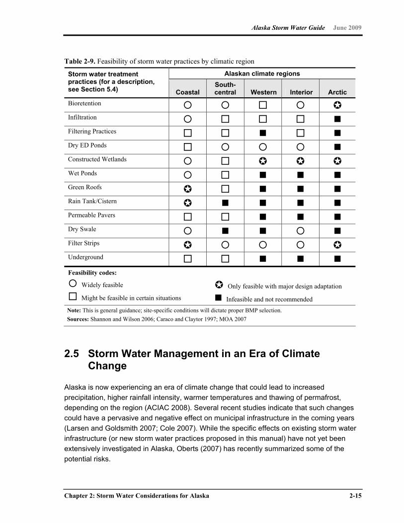
Alaska Storm Water Guide June 2009
Chapter 2: Storm Water Considerations for Alaska 2-15
Table 2-9. Feasibility of storm water practices by climatic region
Alaskan climate regions Storm water treatment practices (for a description, see Section 5.4) Coastal
South-central Western Interior Arctic
Bioretention Infiltration Filtering Practices Dry ED Ponds Constructed Wetlands Wet Ponds Green Roofs Rain Tank/Cistern Permeable Pavers Dry Swale Filter Strips Underground Feasibility codes:
Widely feasible
Might be feasible in certain situations
Only feasible with major design adaptation
Infeasible and not recommended Note: This is general guidance; site-specific conditions will dictate proper BMP selection. Sources: Shannon and Wilson 2006; Caraco and Claytor 1997; MOA 2007
2.5 Storm Water Management in an Era of Climate Change
Alaska is now experiencing an era of climate change that could lead to increased
precipitation, higher rainfall intensity, warmer temperatures and thawing of permafrost,
depending on the region (ACIAC 2008). Several recent studies indicate that such changes
could have a pervasive and negative effect on municipal infrastructure in the coming years
(Larsen and Goldsmith 2007; Cole 2007). While the specific effects on existing storm water
infrastructure (or new storm water practices proposed in this manual) have not yet been
extensively investigated in Alaska, Oberts (2007) has recently summarized some of the
potential risks.

Alaska Storm Water Guide June 2009
2-16 Chapter 2: Storm Water Considerations for Alaska
The Alaska Climate Impact Assessment Commission (2008) strongly recommends an
adaptive engineering approach to minimize the risks to future storm water infrastructure, and
specifically noted the critical need to update TP-47 rainfall records (which date to the mid-
1960s) and improve engineering standards to respond to an era of changing climate.
Although a full review of the effects of climate change on storm water design is beyond the
scope of this initial manual, reviewers should carefully scrutinize the options presented to
see how they might withstand the following:
More intense summer rainfall events
More frequent winter rain events, including rain on snowpack/frozen ground
Gradual thawing of the permafrost layer
Increased intensity of flooding events
Increased use of salt and deicers
Longer growing season
More rapid spring melt and breakup
2.6 Winter Construction
Given the short growing season, milder winters and adoption of new building techniques in
Alaska, construction might now extend or even be initiated in the winter season. Even when
construction ceases in the winter, soils could be exposed until building conditions improve in
the spring. Given frozen soils, it might be difficult or impossible to stabilize soils with sprays,
mulch or vegetative cover. In addition, many common erosion and sediment control
practices that work well during the growing season, perform much worse during winter
conditions, as shown in Table 2-10. This often means that soils and slopes are left bare
throughout the winter only to be exposed to the erosive forces of meltwater and spring runoff
when little protection is in place. Consequently, sediment delivery from construction sites
could become extremely high, unless aggressive measures are made before, during and
after winter to keep soil in place. A series of recommended erosion and sediment control
practices to apply to winter construction sites is in Section 3.4.5a. These Fall-Winter-Spring
practices are particularly important for all climatic regions other than the Coastal Region.
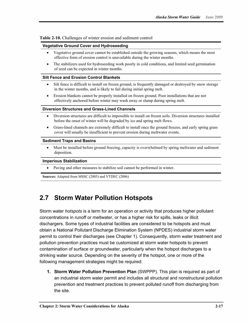
Alaska Storm Water Guide June 2009
Chapter 2: Storm Water Considerations for Alaska 2-17
Table 2-10. Challenges of winter erosion and sediment control
Vegetative Ground Cover and Hydroseeding Vegetative ground cover cannot be established outside the growing seasons, which means the most
effective form of erosion control is unavailable during the winter months. The stabilizers used for hydroseeding work poorly in cold conditions, and limited seed germination
of seed can be expected in winter months.
Silt Fence and Erosion Control Blankets Silt fence is difficult to install on frozen ground, is frequently damaged or destroyed by snow storage
in the winter months, and is likely to fail during initial spring melt. Erosion blankets cannot be properly installed on frozen ground. Poor installations that are not
effectively anchored before winter may wash away or slump during spring melt.
Diversion Structures and Grass-Lined Channels Diversion structures are difficult to impossible to install on frozen soils. Diversion structures installed
before the onset of winter will be degraded by ice and spring melt flows. Grass-lined channels are extremely difficult to install once the ground freezes, and early spring grass
cover will usually be insufficient to prevent erosion during meltwater events.
Sediment Traps and Basins Must be installed before ground freezing, capacity is overwhelmed by spring meltwater and sediment
deposition.
Imperious Stabilization Paving and other measures to stabilize soil cannot be performed in winter.
Sources: Adapted from MSSC (2005) and VTDEC (2006)
2.7 Storm Water Pollution Hotspots
Storm water hotspots is a term for an operation or activity that produces higher pollutant
concentrations in runoff or meltwater, or has a higher risk for spills, leaks or illicit
dischargers. Some types of industrial facilities are considered to be hotspots and must
obtain a National Pollutant Discharge Elimination System (NPDES) industrial storm water
permit to control their discharges (see Chapter 1). Consequently, storm water treatment and
pollution prevention practices must be customized at storm water hotspots to prevent
contamination of surface or groundwater, particularly when the hotspot discharges to a
drinking water source. Depending on the severity of the hotspot, one or more of the
following management strategies might be required:
1. Storm Water Pollution Prevention Plan (SWPPP). This plan is required as part of
an industrial storm water permit and includes all structural and nonstructural pollution
prevention and treatment practices to prevent polluted runoff from discharging from
the site.
Alaska Storm Water Guide June 2009
2-18 Chapter 2: Storm Water Considerations for Alaska
2. Source Control Plan (SCP). This plan is recommended for new development
projects that have potential to become a hotspot and includes an addendum to the
storm water plan on pollution prevention practices to reduce contact of pollutants
with rainfall or snowmelt.
3. Snowmelt Management Plan (SMP). This plan could apply to an existing site or
new development project and outlines the process for clearing, storing, removing and
treating snow from the site to minimize snowmelt pollution. Guidance on developing
these plans are in MOA (2007) and Chapter 9 of MSSC (2005).
4. Infiltration Prohibition (IP). This approach involves a local approval for new
development projects that effectively prohibits infiltration of snowmelt from severe
storm water hotspot to prevent potential groundwater contamination by chloride or
other toxics. In such cases, an alternative storm water practice such as a
bioretention area, sand filter or constructed wetland must be used to filter runoff
before it reaches surface or groundwater. The prohibition of direct infiltration of
hotspot runoff is often used to protect the quality a community water supply.
As shown in Table 2-11, there are a broader group of operations and activities in Alaska that
have potential to become storm water pollution hotspots. The designation is important in that
it can trigger up to four management responses as described above.

Alaska Storm Water Guide June 2009
Chapter 2: Storm Water Considerations for Alaska 2-19
Table 2-11. List of Alaskan storm water hotspots
Recommended management response Storm water hotspot operation or activity SWPPP SCP SMP IP
NPDES industrial permits (see Chapter 1) Industrial machinery and equipment Railroad equipment Airfields and aircraft maintenance areas Fleet storage areas Gas stations Retail/wholesale vehicle/equipment dealers Road construction Construction business (paving, heavy equipment storage and maintenance)
Petroleum storage facilities Port facilities Parking lots (40 or more parking spaces) Rural-horse paddocks Residential-dog kennels Commercial snow dumping and storage area Public works yard Shipyards and repair facilities Metal recyclers Source: Adapted from MDE (2000) and Schueler et al (2004).

This page intentionally left blank

Alaska Storm Water Guide June 2009
Chapter 3: Storm Water Design Considerations and Methods 3-1
Chapter 3 Storm Water Design Considerations and Methods
3.0 Introduction
This section provides an overview of current methods employed to evaluate a suite of
design issues facing Alaska property owners or their designee (herein referred to as
designers), with specific emphasis on methods already used in Alaska. Under some
circumstances, methods evolving from the activities in the lower-48 states are discussed to
provide food-for-thought for Alaska designers and municipalities.
The information in this chapter is targeted at planning and designing permanent storm water
BMPs. Local governments might have their own terminology and reference system for the
documents/calculations submitted to obtain the necessary permits, but for the majority of
Alaska’s land area, state or federal agencies are the permitting authority.
This section discusses considerations for designers preparing engineering plans for
permanent BMPs for submission to Alaska Department of Environmental Conservation
(ADEC) or to the Municipality of Anchorage (MOA), which has developed its own design
considerations. The City of Fairbanks, the City of North Pole, the Fairbanks North Star
Borough (FNSB) and City and Borough of Juneau are in the early stages of developing their
own design considerations. The diverse environmental conditions throughout Alaska
frequently require designers to be aware of local, state, and federal guidelines/design
requirements. This section provides an overview of the elements that should be considered
in permanent BMP design, defines terms for use in the storm water dialog between
regulators and designers, and provides references that individuals can use to advance their
permanent storm water planning.
Alaska Storm Water Guide June 2009
3-2 Chapter 3: Storm Water Design Considerations and Methods
3.1 The Role of Soils
Soils are extremely important to consider when planning for, selecting and designing
permanent storm water management controls. This section discusses resources available
on Alaska soils and some basic concepts for classifying Alaska soils.
Soil surveys conducted by the Natural Resources Conservation Service (NRCS) of the U.S.
Department of Agriculture (USDA) are available for many areas of Alaska (see Link 26 in
Appendix A for the Web link to the surveys).
The Alaska DNR Division of Geological and Geophysical Surveys have mapped the
engineering geology for many areas of Alaska (see Link 27 in Appendix A for the Web link to
these reports).
These resources provide generalized information on soils and characterize soils down to an
order of tens to hundreds of acres. It is probable that even on small sites (less than 5 acres)
there will be localized variation in surface soils and underlying soil horizons. Designers of
permanent BMPs should sufficiently characterize soil variation to establish site-specific
permanent storm water management. For linear projects such as roadways, it is likely that
the type of soil encountered will vary significantly along the project length.
There are two options for designers trying to obtain soil information on their building
locations: (1) hire a professional soil scientist, or (2) obtain an idea of what soil is present by
using the field method described by USDA to do-it-yourself in the Web link below. The
USDA Web site also has useful information on soil characterization, including accepted field
methods for identifying soil texture (see Link 28 in Appendix A).
Many soil structural and hydrologic parameters can be determined once the soil texture has
been classified. For hydrologic calculations, soil infiltration is an important parameter, often
correlated with soil texture. With regard to storm water generation, Alaska soils can be
characterized on the basis of the amount of summertime infiltration expected. Soil infiltration
capacity is described below for high, medium and low infiltration soils and is related to
generalized soil texture classes.
For new development areas, it is important to note whether any portion of the site is non-
discharging (where either no centralized drainage network exists or where sufficient
infiltration exists to minimize runoff for all but the largest rainfall events). An example of the
first case would be a series of homes arrayed along a ridgeline road. While runoff is
generated by impervious surfaces (roof tops and the roadway) any storm water discharge is
dispersed into backyards or open areas. There is no central collection of storm
Alaska Storm Water Guide June 2009
Chapter 3: Storm Water Design Considerations and Methods 3-3
water/snowmelt runoff and, hence, no centralized discharge. The other condition that
creates a non-discharging site is where soil infiltration is greater than the most common
rainfall rates. An example of this is where construction falls on the footprint of soil/gravel
borrow pits. Exposed gravel/cobble will naturally infiltrate runoff during summer conditions
and help absorb snowmelt during winter thaw conditions.
High Infiltration Soils This condition occurs where shallow or sandy soils are over gravels/cobble layers or areas
where overburden soils have been removed/excavated to expose gravel/cobble sublayers.
The soil texture classes typically associated with high infiltration rates are sandy and sandy
loam soils and soils with high percentages of gravel and cobble (soils that have a sustained
infiltration rate greater or equal to 0.5 inch per hour).
For sites with high infiltration soils, a reasonable case can be made that minimum
permanent BMPs are required if the runoff from impervious surfaces can be managed by
routing the flow onto adjacent high infiltration pervious area. The site might actually have no
discharge for the majority of rainfall events, even though the runoff generated increases
because of new impervious surfaces.
It should be noted that not all land uses are appropriate for infiltration-type permanent storm
water BMPs. Section 2.7 helps identify storm water pollution hotspots, or land uses that
generate or can generate contaminants that should not be infiltrated.
Moderate Infiltration Soils Silt loam or loam soil classes are examples of moderate infiltration soils, assuming there is
sufficient clearance from water tables, and no low permeability sublayers exist. When
thoroughly wetted, these soils will typically infiltrate less than 0.5 inch per hour but greater
than 0.1 inch per hour. Moderate infiltration soils could be sufficient to use infiltration-type
BMPs to limit summertime storm water discharges; however, care is required to ensure that
wintertime issues of freezing, freeze/thaw, and snow accumulation are also addressed.
Low Infiltration Soils Low infiltration conditions exist where infiltration is less than 0.1 inch per hour. This condition
is found where soils are naturally slow to infiltrate or where soils freeze easily to create
wintertime impermeable layers. Permafrost areas are considered to be low infiltrating, as are
soils with impervious layers, such as fragipans or other types of cementous layers. Soil
texture classes typically associated with low infiltration rates are clay, silty clay and clay
loam.
Alaska Storm Water Guide June 2009
3-4 Chapter 3: Storm Water Design Considerations and Methods
Low infiltration soils tend to not be suitable for BMPs designed to infiltrate storm water. As a
result, storm water controls usually incorporate ponding (e.g., detention ponds) or flow-
through systems (e.g., treatment swales) as a means to minimize the impact of storm water
discharge.
Saturated Soils Saturated soils exist where water seasonally ponds because of topography or subsurface
conditions. The NRCS soil surveys provide useful information on the frequency of water
ponding/flooding, the depth-to-groundwater and identifies subsurface restrictive soil layers
as a part of the soil surveys (see Link 29 in Appendix A). In most cases, most or all features
associated with wetlands are evident if saturated soils are present. Wetlands are generally
defined by soil moisture content and vegetative characteristics. A Web link to the process for
defining a wetland provided by the COE (COE 2007) is in Appendix A (see Link 30).
Areas with seasonally saturated soils are probably inappropriate for most construction
activities in the absence of corrective measures. In general, fill material is placed upon these
soils to raise the site elevation sufficiently to allow the installation of structures. Designers
should consider storm water BMPs that use ponding (e.g., detention ponds, wetlands) or
flow-through systems (e.g., treatment swales) as a means to minimize the effects of storm
water discharge.
Unique problems are presented by organic soils found in the muskegs. Decomposed peat
has a tremendous water-holding capacity, so that when it is moved or disturbed during
construction, not only does the soil break down and liquefy, but the water is also released. In
addition, often the muskegs are underlain by an impermeable layer of glacial till, which
produces fine sediments once disturbed.
For Alaska designers considering developing on or near saturated soils, it is recommended
reviewing the contents of Section 3.2.3 (Wetlands).
Overview of Soil Hydrologic Analysis Alaska designers can choose from an array of accepted mathematical models for estimating
soil hydrologic losses due to infiltration. In some cases, local municipalities will provide
designers with approved hydrologic modeling software and a range of accepted parameter
values. When applying mathematical models, reasonable assumptions should be made that
are applicable to the site and are representative of site conditions. Data needs vary among
the models, some more intensively than others. Builders often hire professionals to
implement their hydrologic analysis, because the selection of parameters requires
professional judgment.
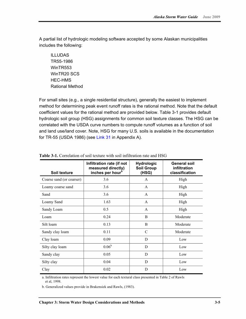
Alaska Storm Water Guide June 2009
Chapter 3: Storm Water Design Considerations and Methods 3-5
A partial list of hydrologic modeling software accepted by some Alaskan municipalities
includes the following:
ILLUDAS
TR55-1986
WinTR553
WinTR20 SCS
HEC-HMS
Rational Method
For small sites (e.g., a single residential structure), generally the easiest to implement
method for determining peak event runoff rates is the rational method. Note that the default
coefficient values for the rational method are provided below. Table 3-1 provides default
hydrologic soil group (HSG) assignments for common soil texture classes. The HSG can be
correlated with the USDA curve numbers to compute runoff volumes as a function of soil
and land use/land cover. Note, HSG for many U.S. soils is available in the documentation
for TR-55 (USDA 1986) (see Link 31 in Appendix A).
Table 3-1. Correlation of soil texture with soil infiltration rate and HSG
Soil texture
Infiltration rate (if not measured directly) inches per houra
Hydrologic Soil Group
(HSG)
General soil infiltration
classification Coarse sand (or coarser) 3.6 A High
Loamy coarse sand 3.6 A High
Sand 3.6 A High
Loamy Sand 1.63 A High
Sandy Loam 0.5 A High
Loam 0.24 B Moderate
Silt loam 0.13 B Moderate
Sandy clay loam 0.11 C Moderate
Clay loam 0.09 D Low
Silty clay loam 0.06b D Low
Sandy clay 0.05 D Low
Silty clay 0.04 D Low
Clay 0.02 D Low
a. Infiltration rates represent the lowest value for each textural class presented in Table 2 of Rawls et al, 1998.
b. Generalized values provide in Brakensiek and Rawls, (1983).
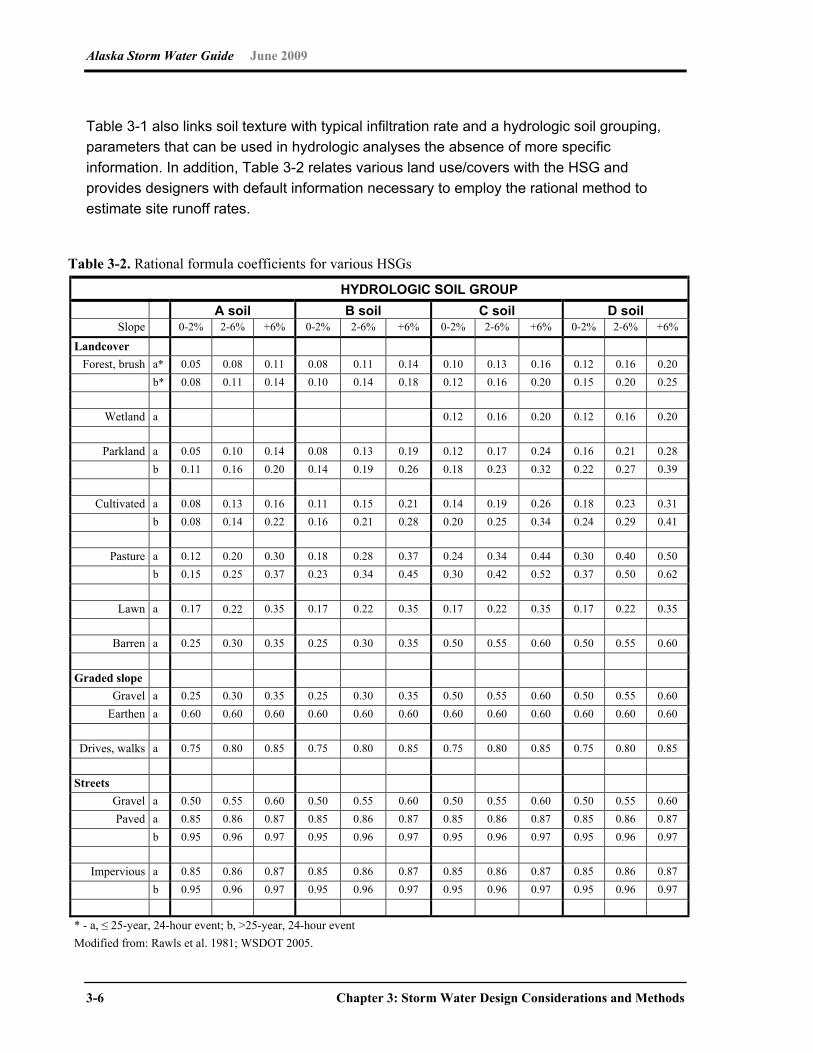
Alaska Storm Water Guide June 2009
3-6 Chapter 3: Storm Water Design Considerations and Methods
Table 3-1 also links soil texture with typical infiltration rate and a hydrologic soil grouping,
parameters that can be used in hydrologic analyses the absence of more specific
information. In addition, Table 3-2 relates various land use/covers with the HSG and
provides designers with default information necessary to employ the rational method to
estimate site runoff rates.
Table 3-2. Rational formula coefficients for various HSGs HYDROLOGIC SOIL GROUP
A soil B soil C soil D soil Slope 0-2% 2-6% +6% 0-2% 2-6% +6% 0-2% 2-6% +6% 0-2% 2-6% +6%
Landcover Forest, brush a* 0.05 0.08 0.11 0.08 0.11 0.14 0.10 0.13 0.16 0.12 0.16 0.20
b* 0.08 0.11 0.14 0.10 0.14 0.18 0.12 0.16 0.20 0.15 0.20 0.25
Wetland a 0.12 0.16 0.20 0.12 0.16 0.20
Parkland a 0.05 0.10 0.14 0.08 0.13 0.19 0.12 0.17 0.24 0.16 0.21 0.28 b 0.11 0.16 0.20 0.14 0.19 0.26 0.18 0.23 0.32 0.22 0.27 0.39
Cultivated a 0.08 0.13 0.16 0.11 0.15 0.21 0.14 0.19 0.26 0.18 0.23 0.31 b 0.08 0.14 0.22 0.16 0.21 0.28 0.20 0.25 0.34 0.24 0.29 0.41
Pasture a 0.12 0.20 0.30 0.18 0.28 0.37 0.24 0.34 0.44 0.30 0.40 0.50 b 0.15 0.25 0.37 0.23 0.34 0.45 0.30 0.42 0.52 0.37 0.50 0.62
Lawn a 0.17 0.22 0.35 0.17 0.22 0.35 0.17 0.22 0.35 0.17 0.22 0.35
Barren a 0.25 0.30 0.35 0.25 0.30 0.35 0.50 0.55 0.60 0.50 0.55 0.60
Graded slope Gravel a 0.25 0.30 0.35 0.25 0.30 0.35 0.50 0.55 0.60 0.50 0.55 0.60
Earthen a 0.60 0.60 0.60 0.60 0.60 0.60 0.60 0.60 0.60 0.60 0.60 0.60
Drives, walks a 0.75 0.80 0.85 0.75 0.80 0.85 0.75 0.80 0.85 0.75 0.80 0.85
Streets Gravel a 0.50 0.55 0.60 0.50 0.55 0.60 0.50 0.55 0.60 0.50 0.55 0.60 Paved a 0.85 0.86 0.87 0.85 0.86 0.87 0.85 0.86 0.87 0.85 0.86 0.87
b 0.95 0.96 0.97 0.95 0.96 0.97 0.95 0.96 0.97 0.95 0.96 0.97
Impervious a 0.85 0.86 0.87 0.85 0.86 0.87 0.85 0.86 0.87 0.85 0.86 0.87 b 0.95 0.96 0.97 0.95 0.96 0.97 0.95 0.96 0.97 0.95 0.96 0.97
* - a, ≤ 25-year, 24-hour event; b, >25-year, 24-hour event Modified from: Rawls et al. 1981; WSDOT 2005.

Alaska Storm Water Guide June 2009
Chapter 3: Storm Water Design Considerations and Methods 3-7
3.2 Considerations for Protecting Sensitive Receiving Waters
Alaska designers should be aware of multiple categories of waters that are considered
sensitive. Sensitive waters tend to receive special attention from regulating agencies
because of the use of the waters, (e.g., supporting drinking water, supporting high-value fish
habitat). This section reviews the most common circumstances of which Alaska designers
should be aware and provides references and contacts for them to determine the extent and
nature of potential issues they might face at their construction site.
3.2.1 Drinking Water Source Protection
Designers should note where storm water discharge is expected to discharge into drinking
water source protection areas. Local communities should be contacted to determine where
surface or shallow groundwater is used or contributes to a public water source. In addition,
ADEC’s Division of Environmental Health provides information on the locations where
drinking water protection efforts are underway (see the Web Link 32 in Appendix A).
For drinking water protection areas, additional steps might be required to treat storm water
discharge before its departure from the development site boundaries (for details, see the
discussion of the UIC Program and related links in Chapter 1).
3.2.2 Anadromous Fish Habitat and Other Resource Protection Areas
As described in Chapter 1, the Anadromous Fish Act requires that an individual or
governmental agency provide prior notification and obtain approval from the ADF&G “to
construct a hydraulic project or use, divert, obstruct, pollute, or change the natural flow or
bed” of a specified anadromous waterbody or “to use wheeled, tracked, or excavating
equipment or log-dragging equipment in the bed” of a specified anadromous waterbody. As
it relates to permanent storm water BMPs, designers should address two basic concerns:
The discharge of storm water pollutants (e.g., TSS/silts that clog spawning beds)
Sustaining predevelopment flow rates to protect stream habitat
In addition to Alaskan waters that have been designated as anadromous fish habitat, select
communities have further prioritized their waterbodies. Designers should contact their local
community to assess if the storm water from new developments/redevelopments will reach
priority waters. In some cases, additional storm water controls might be required for new
development activities. Examples of this include detention/retention ponds with long
residence times and flow-velocity, energy-dissipation devices.
Alaska Storm Water Guide June 2009
3-8 Chapter 3: Storm Water Design Considerations and Methods
The ADF&G Division of Habitat is responsible for identifying anadromous waters and
provides information through its Web site (Link 33 in Appendix A).
3.2.3 Construction Adjacent to Wetlands and Discharges to Wetlands
The location of proposed construction activities establishes which permitting authority
Alaska designers should first contact regarding wetlands. Some Alaska communities have
already approved procedures for assessing wetlands, have already delineated their
wetlands and have specific requirements if wetlands are adjacent to proposed construction
sites. Depending on location, the interaction between permanent storm water BMPs and
wetlands will be established through the COE, ADEC, the local municipality (e.g., Juneau or
Anchorage), or a combination of them all. This section summarizes some of the roles/efforts
of the different regulatory agencies, and provides designers with contacts/resources for
assessment of site-specific requirements.
Municipal Wetlands Management Efforts Designers seeking to discharge to wetlands in MOA must obtain site-specific guidance from
MOA’s Physical Planning Section for Class C Wetlands. To facilitate the process, MOA has
prepared an atlas indicating where wetlands are in the Anchorage Bowl and Eagle River
area of MOA (see Web Link 34 in Appendix A).
In addition, the Anchorage Storm Water Treatment in Wetlands: 2002 Guidance provides
pretreatment requirements for discharge to natural wetlands (see Link 35 in Appendix A).
To obtain ordinances related to the discharge of storm water to natural wetlands in the
jurisdiction of other Alaska municipalities, designers should contact the public works or
planning department of the municipality.
ADEC Wetlands Assessment Efforts ADEC has established local guidance for assessing wetlands and wetland functionality on
the basis of the hydrogeomorphic approach (HGM) methodology. This guidance affects
areas inside and outside the Coastal Management Program. Wetlands are managed to
assure adequate water flow, nutrients, and oxygen levels and avoid adverse effects on
natural drainage patterns, the destruction of important habitat, and the discharge of toxic
substances. ADEC (2003a, 2003b) and ADEC/USGS (1999) has developed draft guidance
for the (1) Cook Inlet Basin, (2) Southeast and South Central Alaska, and (3) Interior Alaska.
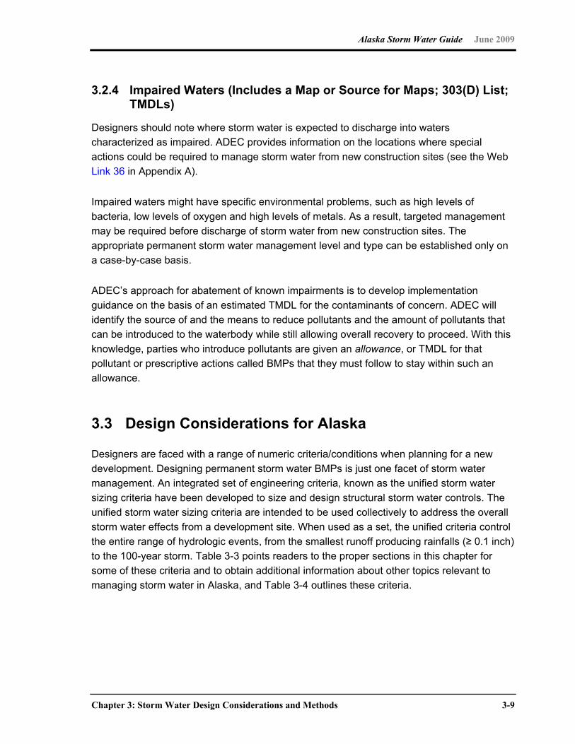
Alaska Storm Water Guide June 2009
Chapter 3: Storm Water Design Considerations and Methods 3-9
3.2.4 Impaired Waters (Includes a Map or Source for Maps; 303(D) List; TMDLs)
Designers should note where storm water is expected to discharge into waters
characterized as impaired. ADEC provides information on the locations where special
actions could be required to manage storm water from new construction sites (see the Web
Link 36 in Appendix A).
Impaired waters might have specific environmental problems, such as high levels of
bacteria, low levels of oxygen and high levels of metals. As a result, targeted management
may be required before discharge of storm water from new construction sites. The
appropriate permanent storm water management level and type can be established only on
a case-by-case basis.
ADEC’s approach for abatement of known impairments is to develop implementation
guidance on the basis of an estimated TMDL for the contaminants of concern. ADEC will
identify the source of and the means to reduce pollutants and the amount of pollutants that
can be introduced to the waterbody while still allowing overall recovery to proceed. With this
knowledge, parties who introduce pollutants are given an allowance, or TMDL for that
pollutant or prescriptive actions called BMPs that they must follow to stay within such an
allowance.
3.3 Design Considerations for Alaska
Designers are faced with a range of numeric criteria/conditions when planning for a new
development. Designing permanent storm water BMPs is just one facet of storm water
management. An integrated set of engineering criteria, known as the unified storm water
sizing criteria have been developed to size and design structural storm water controls. The
unified storm water sizing criteria are intended to be used collectively to address the overall
storm water effects from a development site. When used as a set, the unified criteria control
the entire range of hydrologic events, from the smallest runoff producing rainfalls (≥ 0.1 inch)
to the 100-year storm. Table 3-3 points readers to the proper sections in this chapter for
some of these criteria and to obtain additional information about other topics relevant to
managing storm water in Alaska, and Table 3-4 outlines these criteria.

Alaska Storm Water Guide June 2009
3-10 Chapter 3: Storm Water Design Considerations and Methods
Table 3-3. Storm water design cross-reference for Alaska designers
Criteria/condition Characterization of
design standard/criteria Primary decision point Reference
section Storm Water Quality Water Quality Volume State minimum standard or
state-adopted federal numeric criteria*
Identification of regulatory condition
Section 3.3.1
Low-Impact Designs Best Professional Judgment Identification of runoff reduction opportunities
Section 3.3.5
Discharge Point Design Groundwater Recharge Volume
Per local ordinance Contact local municipality Section 3.3.2
Activity-Specific Designs Road Crossings Either local ordinance or
AASHTO** Drainage Guidelines
Identification of controlling authority
Section 3.3.4
Flood Prevention Either local ordinance or federal criteria
Identification of controlling authority
Section 3.3.4
Channel Protection Recommendations based on best current practice
Identification of design goal
Section 3.3.3
* Local ordinance may exceed state or federal requirements ** AASHTO = American Association of State Highway and Transportation Officials
Table 3-4. Unified sizing criteria
Sizing criteria Recommended method
Water Quality Volume WQv (acre-feet)
Treat the runoff from 90% of the storms that occur in an average year. For Alaska, this equates to providing water quality treatment for the runoff resulting from a rainfall depth of 1.25 inches or less. The goal is to reduce average annual post-development TSS loadings by 80%. WQv = (Rv) × (A) × (P) / 12 where Rv = site runoff volume coefficient; A = site drainage area (acres); P = design rainfall depth (90% cumulative frequency depth) (~ 0.5 to 1.25 inches)
Recharge Volume Rev (acre-feet)
Fraction of WQv, depending on predevelopment HSG. Rev = [(S)(Rv)(A)] / 12 where S = soil specific recharge factor in inches
Channel Protection Storage Volume Cpv
Provide 24 hours of extended detention of the runoff from the 1-year, 24-hour duration storm event to reduce bank-full flows and protect downstream channels from erosive velocities and unstable conditions.
Overbank Flood Protection Qp
Provide peak discharge control of the 5-year storm event such that the post-development peak rate does not exceed the downstream conveyance capacity or cause overbank flooding in local urban watersheds. Some jurisdictions may require peak discharge control for the 2-year storm event.
Extreme Flood Protection Qf
Evaluate the effects of the 100-year storm on the storm water management system, adjacent property, and downstream facilities and property. Manage the effects of the extreme storm event through detention controls or floodplain management.
(Adapted from the Iowa Stormwater Management Manual, Version 1; 2007)
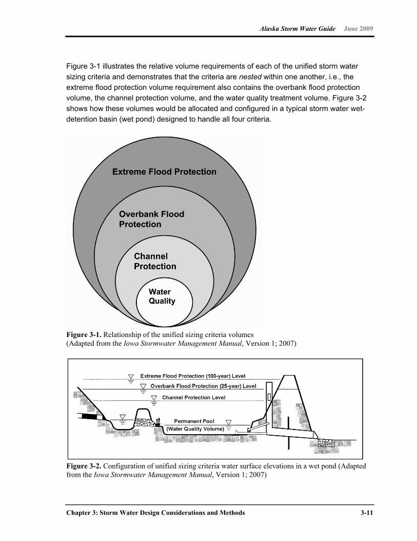
Alaska Storm Water Guide June 2009
Chapter 3: Storm Water Design Considerations and Methods 3-11
Figure 3-1 illustrates the relative volume requirements of each of the unified storm water
sizing criteria and demonstrates that the criteria are nested within one another, i.e., the
extreme flood protection volume requirement also contains the overbank flood protection
volume, the channel protection volume, and the water quality treatment volume. Figure 3-2
shows how these volumes would be allocated and configured in a typical storm water wet-
detention basin (wet pond) designed to handle all four criteria.
Figure 3-1. Relationship of the unified sizing criteria volumes (Adapted from the Iowa Stormwater Management Manual, Version 1; 2007)
Figure 3-2. Configuration of unified sizing criteria water surface elevations in a wet pond (Adapted from the Iowa Stormwater Management Manual, Version 1; 2007)
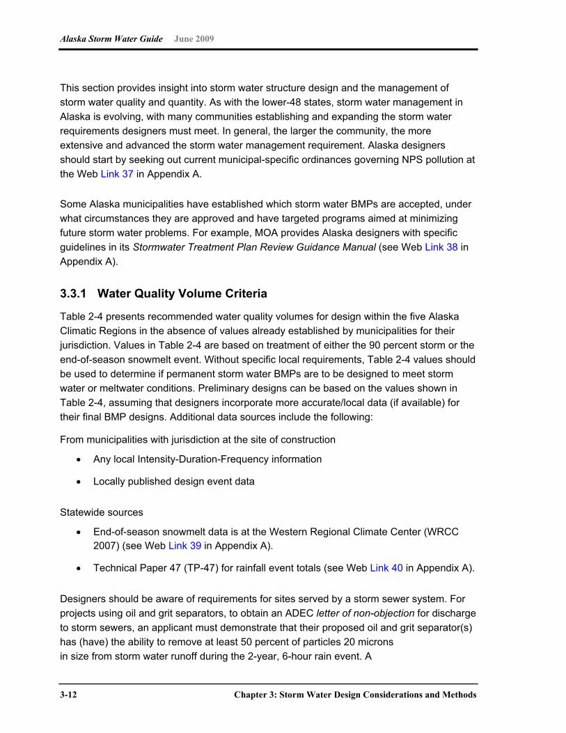
Alaska Storm Water Guide June 2009
3-12 Chapter 3: Storm Water Design Considerations and Methods
This section provides insight into storm water structure design and the management of
storm water quality and quantity. As with the lower-48 states, storm water management in
Alaska is evolving, with many communities establishing and expanding the storm water
requirements designers must meet. In general, the larger the community, the more
extensive and advanced the storm water management requirement. Alaska designers
should start by seeking out current municipal-specific ordinances governing NPS pollution at
the Web Link 37 in Appendix A.
Some Alaska municipalities have established which storm water BMPs are accepted, under
what circumstances they are approved and have targeted programs aimed at minimizing
future storm water problems. For example, MOA provides Alaska designers with specific
guidelines in its Stormwater Treatment Plan Review Guidance Manual (see Web Link 38 in
Appendix A).
3.3.1 Water Quality Volume Criteria
Table 2-4 presents recommended water quality volumes for design within the five Alaska
Climatic Regions in the absence of values already established by municipalities for their
jurisdiction. Values in Table 2-4 are based on treatment of either the 90 percent storm or the
end-of-season snowmelt event. Without specific local requirements, Table 2-4 values should
be used to determine if permanent storm water BMPs are to be designed to meet storm
water or meltwater conditions. Preliminary designs can be based on the values shown in
Table 2-4, assuming that designers incorporate more accurate/local data (if available) for
their final BMP designs. Additional data sources include the following:
From municipalities with jurisdiction at the site of construction
Any local Intensity-Duration-Frequency information
Locally published design event data
Statewide sources
End-of-season snowmelt data is at the Western Regional Climate Center (WRCC 2007) (see Web Link 39 in Appendix A).
Technical Paper 47 (TP-47) for rainfall event totals (see Web Link 40 in Appendix A).
Designers should be aware of requirements for sites served by a storm sewer system. For
projects using oil and grit separators, to obtain an ADEC letter of non-objection for discharge
to storm sewers, an applicant must demonstrate that their proposed oil and grit separator(s)
has (have) the ability to remove at least 50 percent of particles 20 microns
in size from storm water runoff during the 2-year, 6-hour rain event. A
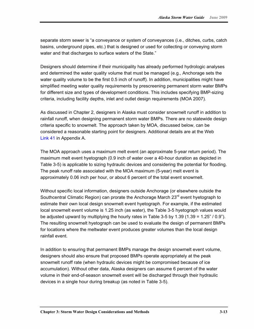
Alaska Storm Water Guide June 2009
Chapter 3: Storm Water Design Considerations and Methods 3-13
separate storm sewer is “a conveyance or system of conveyances (i.e., ditches, curbs, catch
basins, underground pipes, etc.) that is designed or used for collecting or conveying storm
water and that discharges to surface waters of the State.”
Designers should determine if their municipality has already performed hydrologic analyses
and determined the water quality volume that must be managed (e.g., Anchorage sets the
water quality volume to be the first 0.5 inch of runoff). In addition, municipalities might have
simplified meeting water quality requirements by prescreening permanent storm water BMPs
for different size and types of development conditions. This includes specifying BMP-sizing
criteria, including facility depths, inlet and outlet design requirements (MOA 2007).
As discussed in Chapter 2, designers in Alaska must consider snowmelt runoff in addition to
rainfall runoff, when designing permanent storm water BMPs. There are no statewide design
criteria specific to snowmelt. The approach taken by MOA, discussed below, can be
considered a reasonable starting point for designers. Additional details are at the Web
Link 41 in Appendix A.
The MOA approach uses a maximum melt event (an approximate 5-year return period). The
maximum melt event hyetograph (0.9 inch of water over a 40-hour duration as depicted in
Table 3-5) is applicable to sizing hydraulic devices and considering the potential for flooding.
The peak runoff rate associated with the MOA maximum (5-year) melt event is
approximately 0.06 inch per hour, or about 6 percent of the total event snowmelt.
Without specific local information, designers outside Anchorage (or elsewhere outside the
Southcentral Climatic Region) can prorate the Anchorage March 23rd event hyetograph to
estimate their own local design snowmelt event hyetograph. For example, if the estimated
local snowmelt event volume is 1.25 inch (as water), the Table 3-5 hyetograph values would
be adjusted upward by multiplying the hourly rates in Table 3-5 by 1.39 (1.39 = 1.25” / 0.9”).
The resulting snowmelt hyetograph can be used to evaluate the design of permanent BMPs
for locations where the meltwater event produces greater volumes than the local design
rainfall event.
In addition to ensuring that permanent BMPs manage the design snowmelt event volume,
designers should also ensure that proposed BMPs operate appropriately at the peak
snowmelt runoff rate (when hydraulic devices might be compromised because of ice
accumulation). Without other data, Alaska designers can assume 6 percent of the water
volume in their end-of-season snowmelt event will be discharged through their hydraulic
devices in a single hour during breakup (as noted in Table 3-5).
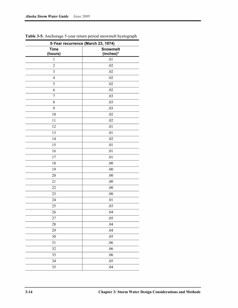
Alaska Storm Water Guide June 2009
3-14 Chapter 3: Storm Water Design Considerations and Methods
Table 3-5. Anchorage 5-year return period snowmelt hyetograph
5-Year recurrence (March 23, 1974) Time
(hours) Snowmelt (inches)*
1 .01 2 .02 3 .02 4 .02 5 .02 6 .02 7 .03 8 .03 9 .03
10 .02 11 .02 12 .01 13 .01 14 .02 15 .01 16 .01 17 .01 18 .00 19 .00 20 .00 21 .00 22 .00 23 .00 24 .01 25 .03 26 .04 27 .05 28 .04 29 .04 30 .05 31 .06 32 .06 33 .06 34 .05 35 .04
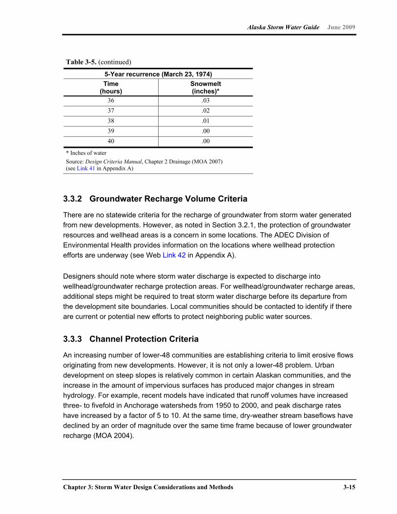
Alaska Storm Water Guide June 2009
Chapter 3: Storm Water Design Considerations and Methods 3-15
Table 3-5. (continued)
5-Year recurrence (March 23, 1974) Time
(hours) Snowmelt (inches)*
36 .03 37 .02 38 .01 39 .00 40 .00
* Inches of water Source: Design Criteria Manual, Chapter 2 Drainage (MOA 2007) (see Link 41 in Appendix A)
3.3.2 Groundwater Recharge Volume Criteria
There are no statewide criteria for the recharge of groundwater from storm water generated
from new developments. However, as noted in Section 3.2.1, the protection of groundwater
resources and wellhead areas is a concern in some locations. The ADEC Division of
Environmental Health provides information on the locations where wellhead protection
efforts are underway (see Web Link 42 in Appendix A).
Designers should note where storm water discharge is expected to discharge into
wellhead/groundwater recharge protection areas. For wellhead/groundwater recharge areas,
additional steps might be required to treat storm water discharge before its departure from
the development site boundaries. Local communities should be contacted to identify if there
are current or potential new efforts to protect neighboring public water sources.
3.3.3 Channel Protection Criteria
An increasing number of lower-48 communities are establishing criteria to limit erosive flows
originating from new developments. However, it is not only a lower-48 problem. Urban
development on steep slopes is relatively common in certain Alaskan communities, and the
increase in the amount of impervious surfaces has produced major changes in stream
hydrology. For example, recent models have indicated that runoff volumes have increased
three- to fivefold in Anchorage watersheds from 1950 to 2000, and peak discharge rates
have increased by a factor of 5 to 10. At the same time, dry-weather stream baseflows have
declined by an order of magnitude over the same time frame because of lower groundwater
recharge (MOA 2004).

Alaska Storm Water Guide June 2009
3-16 Chapter 3: Storm Water Design Considerations and Methods
ADEC recommends that to the extent practicable, the designer maintain postdevelopment
peak runoff rate and average volume at levels that are similar to predevelopment levels,
(such as what is required by MOA). To protect the integrity of stream channels, ADEC
recommends that the increase in runoff volume from the one-year, 24-hour storm event be
fully reduced through an acceptable combination of runoff reduction practices. These
practices reduce runoff volume through canopy interception, soil infiltration, evaporation,
rainfall harvesting, engineered infiltration, extended filtration or evapotranspiration. If runoff
reduction is not feasible, as a general guideline consistent with the unified sizing approach,
designers should provide a minimum of 24 hours of extended detention for the one-year,
24-hour design storm event in a pond or wetland.
The above criteria are intended to protect Alaska’s stream habitat. One study identifies the
typical post-development stream cross-section area as between 2 to 4 times larger than the
preconstruction unless preventive measures are taken (CWP 2000). This channel erosion
degrades stream and riparian habitat, and it increases maintenance costs for roadways.
Accepted Analytical Methods for Assessing Channel Protection Alaska designers can choose from an array of references and accepted mathematical
models for evaluating channel conditions, including the following models for determining the
management of specific locations with stream bank erosion:
Hydrologic Engineering Center (HEC) models including HEC-RAS
Procedures outlined in Chapter 8 of the ADOT&PF Drainage Manual (see Web Link 43 in Appendix A).
Peak flow regression equations (see the USGS report WRI 03-4188 at the Web Link 44 in Appendix A).
Soil Conservation Service methods including TR-55 at the Web Link 45 in Appendix A).
EPA SWMM at the Web Link 46 in Appendix A.
For methods on minimizing hydrologic changes due to new developments, see the
discussion on LID concepts in Section 3.3.5.
3.3.4 Flood Control Criteria
Within their storm water ordinances, local communities/jurisdictions may establish their own
minimum freeboard depth requirements and set the design flow magnitude (i.e., event return
Alaska Storm Water Guide June 2009
Chapter 3: Storm Water Design Considerations and Methods 3-17
frequency) under which hydraulic structures must perform. Alaska designers should contact
the local authorities to identify if local design criteria apply.
Meteorologic and hydrologic conditions in Alaska impose a very real flood risk to structures
and property. Floods typically occur because of summer rainfall events, or in some areas of
the state because of combinations of rainfall and snowmelt. Two types of flood prevention
are discussed in this section: (1) acceptable design of hydraulic structures and (2) flood
avoidance by minimizing storm water generation.
Flooding is the absence of necessary freeboard during high-flow conditions such that
structures (e.g., roadways, buildings) are put at risk because they or their foundations come
into contact with water. Flooding could occur within a newly constructed area because of
insufficient conveyance capacity of nearby structures (e.g., undersized culverts, culverts
temporary plugged by ice), or they could occur downstream of newly constructed areas
because of increased storm water runoff originating from new impervious areas. Both flood
conditions are discussed in this section. At the end of the section, recommendations from
the (U.S. Environmental Protection Agency) EPA regarding potential flood control criteria
are made available for communities that are considering establishing/revising their storm
water ordinances.
Alaska designers might have to evaluate a design flow, a check flow and an extreme event
flow when designing hydraulic structures. Consider the following examples (designers
should check with the appropriate agency for specific design criteria):
Design flows—a culvert passing the 10-year flow with a minimum of 1 foot of freeboard
Check or Review flows—a culvert passing 25-year flows without damage to the road crossing
Extreme Events—no flooding of stream-side buildings because of performance of the culvert
One source of information available to Alaska designers on the hydraulic design of
structures is ADOT&PF, which provides guidance for Alaska roadways. As a result, the
ADOT&PF guidance is universally applicable to Alaska (unless superseded by local
ordinance), and many flooding events involve roadways or roadway crossings.
Table 3-6 contains some current ADOT&PF design criteria. It is recommended that
designers outside of Alaska urban centers consider the recommendations made by
ADOT&PF. However, it is also recommended that designers consider not just the current
upstream hydrology, but what the hydrology will be at build-out (i.e., the expected
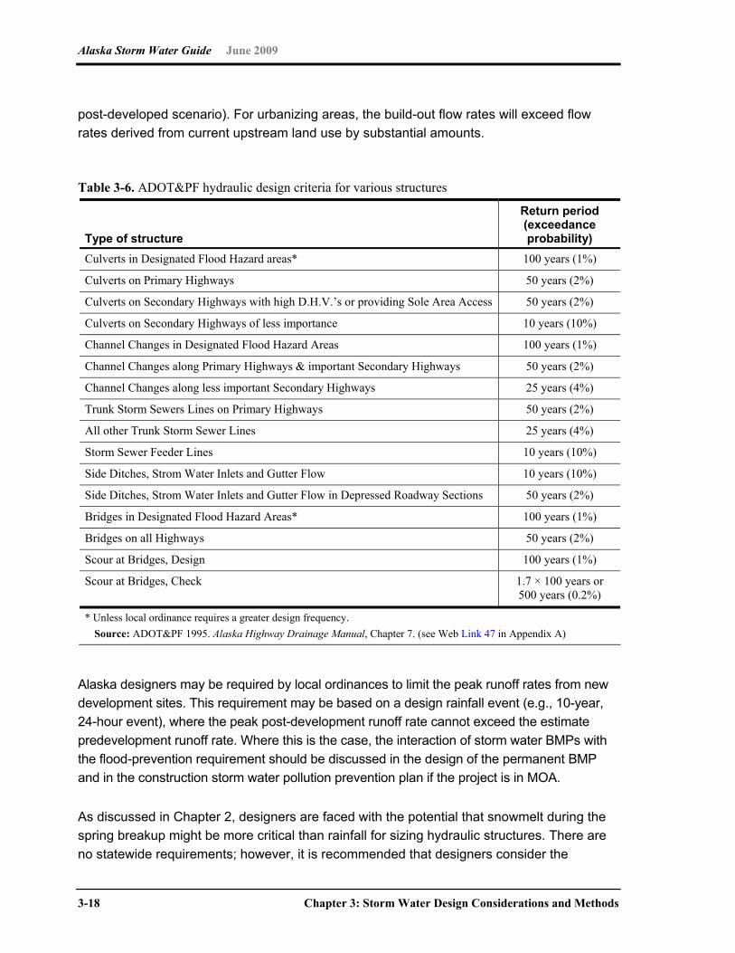
Alaska Storm Water Guide June 2009
3-18 Chapter 3: Storm Water Design Considerations and Methods
post-developed scenario). For urbanizing areas, the build-out flow rates will exceed flow
rates derived from current upstream land use by substantial amounts.
Table 3-6. ADOT&PF hydraulic design criteria for various structures
Type of structure
Return period (exceedance probability)
Culverts in Designated Flood Hazard areas* 100 years (1%)
Culverts on Primary Highways 50 years (2%)
Culverts on Secondary Highways with high D.H.V.’s or providing Sole Area Access 50 years (2%)
Culverts on Secondary Highways of less importance 10 years (10%)
Channel Changes in Designated Flood Hazard Areas 100 years (1%)
Channel Changes along Primary Highways & important Secondary Highways 50 years (2%)
Channel Changes along less important Secondary Highways 25 years (4%)
Trunk Storm Sewers Lines on Primary Highways 50 years (2%)
All other Trunk Storm Sewer Lines 25 years (4%)
Storm Sewer Feeder Lines 10 years (10%)
Side Ditches, Strom Water Inlets and Gutter Flow 10 years (10%)
Side Ditches, Strom Water Inlets and Gutter Flow in Depressed Roadway Sections 50 years (2%)
Bridges in Designated Flood Hazard Areas* 100 years (1%)
Bridges on all Highways 50 years (2%)
Scour at Bridges, Design 100 years (1%)
Scour at Bridges, Check 1.7 × 100 years or 500 years (0.2%)
* Unless local ordinance requires a greater design frequency. Source: ADOT&PF 1995. Alaska Highway Drainage Manual, Chapter 7. (see Web Link 47 in Appendix A)
Alaska designers may be required by local ordinances to limit the peak runoff rates from new
development sites. This requirement may be based on a design rainfall event (e.g., 10-year,
24-hour event), where the peak post-development runoff rate cannot exceed the estimate
predevelopment runoff rate. Where this is the case, the interaction of storm water BMPs with
the flood-prevention requirement should be discussed in the design of the permanent BMP
and in the construction storm water pollution prevention plan if the project is in MOA.
As discussed in Chapter 2, designers are faced with the potential that snowmelt during the
spring breakup might be more critical than rainfall for sizing hydraulic structures. There are
no statewide requirements; however, it is recommended that designers consider the
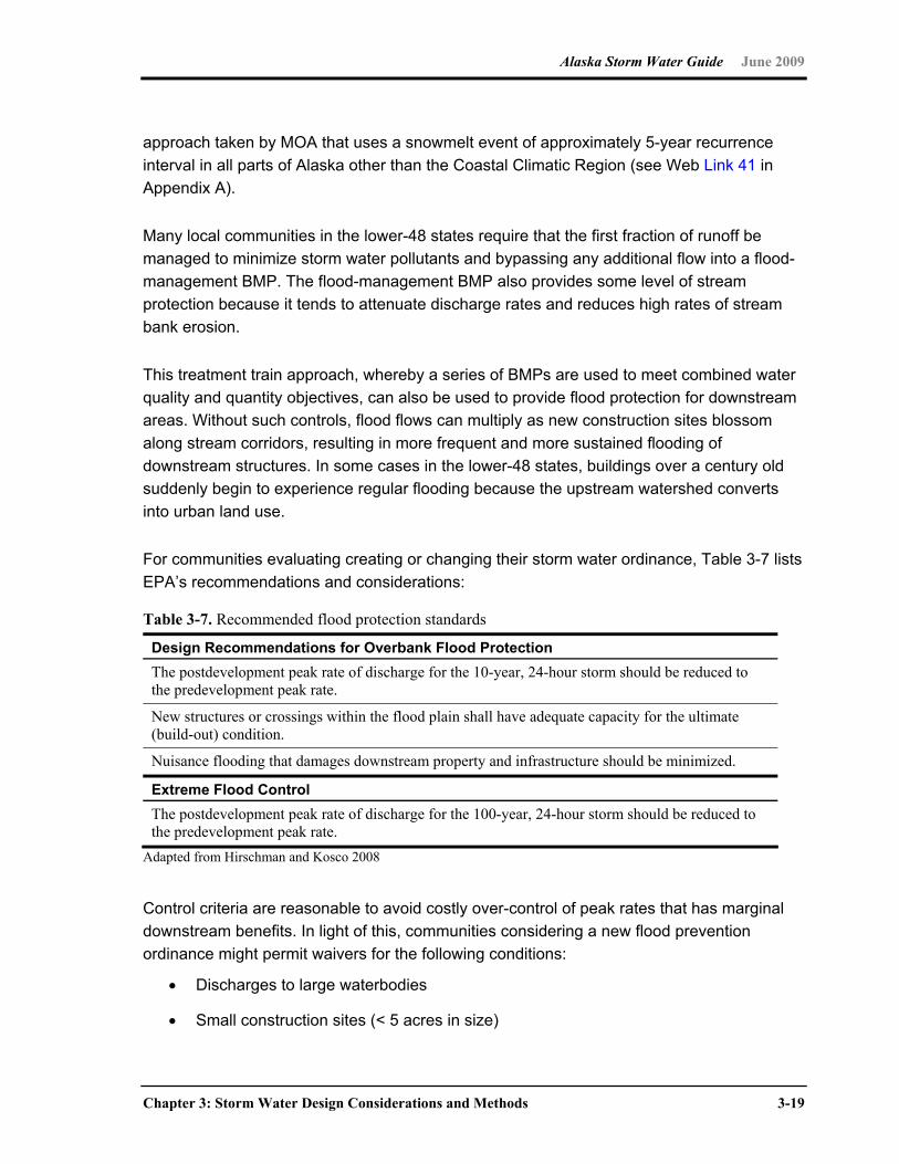
Alaska Storm Water Guide June 2009
Chapter 3: Storm Water Design Considerations and Methods 3-19
approach taken by MOA that uses a snowmelt event of approximately 5-year recurrence
interval in all parts of Alaska other than the Coastal Climatic Region (see Web Link 41 in
Appendix A).
Many local communities in the lower-48 states require that the first fraction of runoff be
managed to minimize storm water pollutants and bypassing any additional flow into a flood-
management BMP. The flood-management BMP also provides some level of stream
protection because it tends to attenuate discharge rates and reduces high rates of stream
bank erosion.
This treatment train approach, whereby a series of BMPs are used to meet combined water
quality and quantity objectives, can also be used to provide flood protection for downstream
areas. Without such controls, flood flows can multiply as new construction sites blossom
along stream corridors, resulting in more frequent and more sustained flooding of
downstream structures. In some cases in the lower-48 states, buildings over a century old
suddenly begin to experience regular flooding because the upstream watershed converts
into urban land use.
For communities evaluating creating or changing their storm water ordinance, Table 3-7 lists
EPA’s recommendations and considerations:
Table 3-7. Recommended flood protection standards
Design Recommendations for Overbank Flood Protection The postdevelopment peak rate of discharge for the 10-year, 24-hour storm should be reduced to the predevelopment peak rate.
New structures or crossings within the flood plain shall have adequate capacity for the ultimate (build-out) condition.
Nuisance flooding that damages downstream property and infrastructure should be minimized.
Extreme Flood Control The postdevelopment peak rate of discharge for the 100-year, 24-hour storm should be reduced to the predevelopment peak rate.
Adapted from Hirschman and Kosco 2008
Control criteria are reasonable to avoid costly over-control of peak rates that has marginal
downstream benefits. In light of this, communities considering a new flood prevention
ordinance might permit waivers for the following conditions:
Discharges to large waterbodies
Small construction sites (< 5 acres in size)
Alaska Storm Water Guide June 2009
3-20 Chapter 3: Storm Water Design Considerations and Methods
Some redevelopment projects (e.g., where site size is small, where historic preservation limits modification, where site geometry/topography make the installation of peak runoff control devices impracticable)
Sites subject to a flood plain study that recommends alternate criteria
Sites where on-site detention will cause a downstream peak flow increase from predevelopment levels because the peaks from the site and watershed coincide.
Subject to applicant justification and local jurisdictional approval
Accepted Modeling Software or Analytical Approaches for Assessing Flood Potential Alaska designers can choose from an array of accepted mathematical models for estimating
flooding potential, including HEC modeling software, including HEC-RAS. Other methods to
consider include peak flow estimation techniques (regression equations (USGS Report WRI
03-4188); Soil Conservation Service methods if evaluating small basins (TR-55 or EPA
SWMM)) coupled with site topography and flood routing analysis.
3.3.5 Low Impact Development/Environmental Site Design
Various types of green-building, smart-design, or low-impact building options exist for land
developers. Herein, these are collectively referred to as low impact development (LID),
although a suite of technical and trade names exist for the same basic concept. Collectively,
LID uses a broad collection of storm water BMPs that can help designers implement storm
water management requirements, provide fiscal and environmental benefits for future land
owners and reduce development costs. Potential advantages of LID to designers in Alaska
are the following:
Helps meet treatment requirements for the water quality volume
Reduces impervious surfaces (roadways), curb, and gutters
Decreases the use of storm drain piping, inlet structures
Eliminates or decreases the size of large storm water ponds
Designers should note that LID is a design concept that can be employed to manage all or
part of the storm water quality volume discussed in Section 3.3.1. It also has the advantage
of reducing channel protection needs and drainage/flooding issues by helping to retain the
predevelopment hydrology.

Alaska Storm Water Guide June 2009
Chapter 3: Storm Water Design Considerations and Methods 3-21
LID is new to Alaska, and local communities are still determining which concepts are
acceptable or applicable and when they could serve as alternatives to more conventional
permanent storm water management controls. The LID concepts that have the highest
potential in Alaska are the following:
Retaining existing or native vegetation
Reducing directly connected imperviousness
Reducing curb and gutter and using vegetated swales
Allowing on-site infiltration for high infiltration areas
Optimizing development to cluster structures
Preserve high-quality land or highly sensitive land
As can be inferred from the above list, LID as applied to Alaska focuses on reductions in
summertime storm water runoff generation and on-site treatment (where appropriate). When
preparing drainage designs and engineering plans for review under 18 AAC 72.600, note
the areas of the site where reductions in runoff volume will occur because of less runoff
being generated, and where runoff is directed onto high infiltration areas.
In addition, there is a potential to employ LID treatment technologies, such as biofiltration
with vegetated swales. Biofiltration has been reviewed by MOA, which has prepared a
guidance document on its application, titled Guidance for Design of Biofiltration Facilities for
Stream Water Quality Control (see the Web Link 48 in Appendix A). Also, see MOA efforts
to introduce rain gardens at the Web Link 49 in Appendix A.
Information Sources Related to LID for Alaska Designers Resources are available to Alaska designers that will help in evaluating of LID or
environmentally friendly design. Alaska weather and soil conditions offer special challenges
that can be evaluated only on a case-by-case basis; however, the suite of models,
calculators and tools available from EPA (see Web Link 50 in Appendix A), offer benefit for
developers interested in green building. See Low-Impact Development: An Integrated
Design Approach, June 1999 at Web Link 51 in Appendix A.
LID application to cold-climate states is progressing in the lower-48 states. The Cooperative
Institute for Coastal and Estuarine Environmental Technology (CICEET), in coordination with
the University of New Hampshire Stormwater Center (UNHSC) completed a cold-weather
study of LID, the findings of which call into question widely held assumptions that runoff
management measures employing filtration, vegetation and natural chemical and microbial
Alaska Storm Water Guide June 2009
3-22 Chapter 3: Storm Water Design Considerations and Methods
processes are ineffective during sub-freezing winter weather. Interested readers can access
the study results (which include installation costs and maintenance requirements) at the
Web Link 52 in Appendix A.
3.4 Storm Water Situation Considerations
3.4.0 Introduction
This section presents a variety of situations encountered in Alaska that warrant special
consideration when selecting or designing storm water controls. Because these situations
could occur anywhere in the state, the following discussion is generalized and, therefore,
does not differentiate among the climatic regions in Alaska. Adaptation of this guidance to
specific conditions is recommended.
3.4.1 Storm Water Strategies for Urban, Suburban and Rural Areas
Alaska development differs greatly in its scale and intensity, and individual communities
need to craft their local storm water criteria to reflect these differences. Three broad
categories of development intensity are considered in this section—rural, suburban and
redevelopment. Rural forms of development are loosely defined as low-density development
that generally is outside MS4s and coastal communities. Most frequently, the development
occurs in boroughs with less urbanized development and might not be subject to local
engineering review because of a lack of local capacity. New suburban development
frequently is within the boundaries or at the margins of MS4s and coastal communities.
Storm water compliance is easier at such greenfield sites because designers have more
flexibility in site layout, and a local land development review process may exist.
Redevelopment occurs within the core of larger MS4s and coastal communities and
frequently involves infill and redevelopment. Storm water compliance at redevelopment sites
is often more difficult because of small project size, space and soil limitations, high land
prices and constraints imposed by the existing storm water conveyance system. In addition,
many storm water treatment practices that work effectively in rural and suburban
watersheds, might not be as feasible at redevelopment sites (e.g., large ponds and
wetlands, filter strips, grass channels).
Because of inherent differences in cost, feasibility and review capacity, it is recommended
that localities customize their storm water criteria to reflect where development occurs (rural,
suburban and redevelopment areas), as described below.
Alaska Storm Water Guide June 2009
Chapter 3: Storm Water Design Considerations and Methods 3-23
Options for Rural Development. The primary approach to improve compliance in more
isolated rural development is to shift away from detailed engineered storm water site plans
to general residential storm water plan with standard conditions for nonstructural storm
water practices. Examples of some of the standard conditions for rural development might
include the following:
Maximum limits on the amount of impervious cover for the site (e.g., 15 percent)
Maximum limits on the footprint of the site which is cleared and graded (25 percent)
Minimum limit for preservation of wetlands, native cover and other conservation areas protected by a perpetual conservation easement
Minimum standards for dirt or paved road construction to prevent erosion
Temporary stabilization and perimeter sediment controls during construction
Fixed widths for stream, wetland and shoreline buffers, if needed
Standard methods to disconnect and treat rooftop runoff over a suitable pervious area
Use of grass channels or swales to convey concentrated runoff from the site
Other standard measures to prevent or reduce runoff from the site
The advantage of this approach, which has been used in several states, is that it sharply
reduces the cost of preparing and reviewing detailed engineering plans, while still providing
maximum use of nonstructural storm water practices that can be shown on standard
construction drawings. Designers and contractors would be subject to enforcement actions if
they fail to meet the standard conditions. The local and state storm water review agency
may still retain the authority to require engineered storm water plans for larger or more
intense development projects in rural areas and projects that discharge to the state highway
system.
Options for Redevelopment. Redevelopment is at the other end of the intensity spectrum
and creates a storm water management paradox. On one hand, stringent storm water
requirements can ensure that incremental pollutant reductions are made within existing
urban watersheds, which are frequently impaired by past land development, and might not
meet water quality standards. On the other hand, stringent storm water requirements can
drive up compliance costs, and become a disincentive for compact smart growth.
Communities that have chosen a balanced approach could involve one or more of the
following options:

Alaska Storm Water Guide June 2009
3-24 Chapter 3: Storm Water Design Considerations and Methods
Define redevelopment in their storm water ordinances through some combination of minimum land area or improved property value such that minor projects are not subject to the water quality volume (WQv).
Eliminate the WQv requirement for redevelopment sites where a 20 percent or greater reduction in post-development impervious cover (IC) is achieved through site redesign.
Reduce the redevelopment WQv requirement to 20 to 50 percent of the greenfield WQv.
Maintain the same WQv as in greenfield settings, but allow developers to pay an IC mitigation fee for any unmet WQv, which is set at the average compliance cost in a greenfield setting.
Eliminate the WQv requirement for redevelopment sites, but charge an impervious cover mitigation fee that is used to design and construct regional storm water and restoration projects elsewhere in the community.
3.4.2 Linear Projects
Linear projects (e.g., roads, pipelines, utilities) are projects that cut across topographic
features, most notably streams, valleys and ridgelines. In many cases, these projects are
many miles long, although they might only be 100 feet at their widest. As a result of their
geometry, storm water discharge points are dispersed all along the project, and the
discharge might be on only one side of the project. In locations with strong cross-slopes
(e.g., cut banks), culverts might be required to pass storm water under the project pathway.
Depending on project location and geometry, storm water might concentrate only where
valley slopes lead to roadside swales or at stream crossings. Designers of linear projects in
Alaska are likely to face high variations in soils and could encounter wetlands and steep
slopes in a single project.
The Federal Highway Administration (see the Web Link 53 in Appendix A) suggests the
suite of storm water borne pollutants from roadways includes the following:
Oil and petroleum
Trash/litter
TSS (from areas eroded because of impervious surface erosion)
Chemical applied during winter conditions (e.g., salt and grit)
Thermal pollution caused by the runoff contacting and flowing over relatively warm pavement

Alaska Storm Water Guide June 2009
Chapter 3: Storm Water Design Considerations and Methods 3-25
Depending on the material being transported, pipelines can also generate some of or all the
pollutants mentioned above. Pipeline projects might have additional storm water risks
associated with either endemic leaks or catastrophic failures of the completed pipeline.
Linear projects also can have impacts because of physical changes of hydrology and
hydraulics. Hydrologic changes commonly encountered originate from impulse discharges
from impervious surfaces (e.g., pavement). High flow rates from either rainfall or rapid
snowmelt can increase erosion potential, particularly where steep slopes abut
excavation/road cuts.
Some common management challenges that designers might face are the following:
Designing, installing and maintaining numerous relatively small BMPs that serve only a fraction of the whole project area
Operating within space limits (e.g., placing BMPs within right-of-way limits)
Dispersing storm water flow evenly into road-side grassed areas where topography is flat (e.g., less than 2 percent)
Ensuring safe travel during wintertime conditions (snow plowing, applications of anti-skid abrasives)
Ensuring access to maintain BMPs while minimizing unintended entry and use by the general public
Using the BMPs with the lowest maintenance costs, while ensuring that they will perform for a long project life
There are a number of approaches to face the challenges and facilitate storm water
management for linear projects:
Use sod-forming grasses adjacent to roadway shoulders and for vegetated swales to serve as filters for suspended solids and metals
Limit the use of curb-gutter sections as much as practical for filtering and thermal pollution control (to give the runoff an opportunity to infiltrate as quickly as practical)
Consider including infiltration berms and retentive grading in areas that are down slope of the roadway/pipeline.
Select and use winter maintenance materials to minimize environmental impacts
Consider porous pavement and other subsurface infiltration methods where natural soils and topography favor such methods

Alaska Storm Water Guide June 2009
3-26 Chapter 3: Storm Water Design Considerations and Methods
Look for opportunities to use extended detention BMPs and constructed wetlands to maximize retention times
Linear project designers should consult these resources:
ADT&PF provides a wide range of reference documents that include engineering requirements/minimum standards applicable to roadways at the Web Link 54 in Appendix A.
Green Highway Partnership provides case studies and reviews innovative technologies applicable to linear projects at the Web Link 55 in Appendix A.
Evolving environmental developments at AASHTO at the Web Link 56 in Appendix A.
Evolving environmental developments at FHWA at the Web Link 57 in Appendix A.
3.4.3 Spatial Projects (e.g., malls and high-density subdivisions)
Shopping malls and apartment/condominium developments are examples of spatial
projects. Typically they range in size from 5 to 20 acres, a large portion of which are made
up of impervious surfaces (e.g., roofs, roadways and parking areas). In general, the site
geometry is targeted to optimize transportation/ parking/ building placement and to meet
vehicle egress requirements. Often available open space is limited in the effort to maximize
the commercial return on the developing area.
Hydrologically, the high levels of imperviousness generate high rates of storm water flow per
acre. Concentrated flow generated from roadway/parking and roof areas flow through efficient
conveyance systems (either below-grade storm water pipelines or in roadside gutters), and
there is a strong tendency to have a relatively few discharge points. In addition, large volumes
of snow have to be managed during wintertime to ensure movement of people and vehicles.
For malls/shopping areas, snow removal is typically contracted out to a snow removal
company, while high-density subdivisions have public plowing or private snow removal.
Pollutants of concern commonly associated with spatial projects include the following:
Trash (e.g., plastic bags, paper litter)
Oil and petroleum dripped from motor vehicles
TSS
Nutrients (e.g., fertilization of green areas)
Thermal pollution caused by the runoff contacting and flowing over relatively warm pavement
Alaska Storm Water Guide June 2009
Chapter 3: Storm Water Design Considerations and Methods 3-27
Spatial projects significantly change the hydrology and hydraulics of a location, and usually
create maintenance issues (e.g. stream bank erosion) if proper management is not
employed. The hydrologic changes commonly encountered originate from impulse
discharges from impervious surfaces (e.g., pavement). It is not uncommon to triple the total
volume of storm water generated from the spatial project land area, as compared to
predevelopment volumes from grassed/forested settings. Efficient conveyance systems
rapidly concentrate flows but provide centralized locations where it is possible to attenuate
storm water flows. In Alaska, high flow rates from spatial projects could be from rainfall or
rapid snowmelt.
Some common management challenges that may face designers are as follows:
Integrating the management to mitigate multiple issues (e.g., linking trash/litter management with snow removal, while operating BMPs that manage storm water volume and water quality)
Ensuring safe travel during wintertime conditions (snow plowing, applications of anti-skid abrasives)
Ensuring that consistent maintenance is provided to shared BMPs or BMPs that service multiple entities (e.g., multiple stores sharing a parking lot)
Ensuring access to maintain BMPs while minimizing unintended entry and use by the general public
There are a number of approaches to face the challenges and facilitate storm water
management for spatial projects:
To the extent practical, minimize impervious cover when establishing the site design
Look for opportunities to maximize vegetative cover, either by retaining existing natural cover or by planting tolerant plant species
For improved cold weather operations, consider design techniques for ponds and wetlands operated in a seasonal mode, which can be found in Chapter 9 of the Minnesota Stormwater Manual (MSSC 2005)
Consider using constructed wetlands, which are in Evaluation of Stormwater Treatment in Constructed Wetlands in Alaska. (FHWA 2004)
Resources are available to facilitate the design of spatial projects and often promote
approaches that minimize storm water costs while improving the performance of permanent
storm water BMPs. As parking areas generally compose a significant portion of spatial
projects, designers are encouraged to consult a recent publication from Anchorage (MOA)

Alaska Storm Water Guide June 2009
3-28 Chapter 3: Storm Water Design Considerations and Methods
regarding parking lot BMPs (Anchorage Parking Lots: 2002 Best Management Practices
Guidance), at the Web Link 58 in Appendix A.
The MOA guide provides a wide range of design and maintenance criteria for designers of
spatial projects, too numerous to provide in their entirety in this document. The Center for
Watershed Protection (CWP) has generated a wide range of literature to facilitate better
designs for spatial situations. For information to help identify opportunities for narrower
roads, smaller parking lots, rooftop disconnection, cluster lots and other better site design
techniques, see the CWP Web site at the Web Link 59 in Appendix A.
3.4.4 Mining Considerations
Mining can be grossly classified as surface mining, underground mining, and in situ mining.
Surface mining, used to excavate ores at or close to the earth’s surface, includes open pit
mining and highwall or strip mining used to excavate coal or other deposits as well as
dredging to excavate placer deposits. Surface mining usually results in the most significant
storm water impacts. In some mining districts, widespread stream disturbance by placer
mining or dredging could be present along with other disturbances from underground mining
or mineral processing. Placer mining is still an important industry in Alaska, and some
abandoned, large-scale dredge operations remain. In some cases, the dredges are still
present in the dredge ponds created as part of the operation. Underground and in situ
mining remove minerals from deeper deposits. Underground mining extracts and removes
ores from beneath the surface and in situ, consists of sinking injection and extraction wells
and then leaching the ore in place to extract the minerals.
A common theme among environmental problems associated with active mining operations
and mine wastes is contamination of all media, including groundwater, soil, sediments, and
surface water. Contamination can result from a host of metals, primarily Arsenic, Cadmium,
Copper, Manganese, Molybdenum, Lead, and Zinc and a wide variety of sources (e.g., acid
drainage and sulfide bearing waste piles, exposed ore zones, heap-leach spoils, mine-waste
piles and sediments, slag piles, fluvial tailings deposits, and tailings and waste rock piles).
Generally, pollutants of concern from abandoned mines are sedimentation of Surface
Waters, acid drainage and contamination of ground and surface waters with metals,
including cyanide. Many mine sites suffer from the uncontrolled discharge of acidified water,
which becomes contaminated as it flows through abandoned mine workings.
For large mines in Alaska, there are a series of state and federal permits required before
mining activities can begin that are intended to limit the effects of mining activities on the
environment. For details of the permits that are required, see ADNR’s Office of Project
Alaska Storm Water Guide June 2009
Chapter 3: Storm Water Design Considerations and Methods 3-29
Management and Permitting Web site at Link 60 in Appendix A. Under state law, a mine
operator must develop a Plan of Operations for mine development and have it reviewed and
approved by the ADNR. An operator must also prepare a Reclamation Plan for rehabilitating
or reclaiming the mine site when mining operations end. The plan must include an
accounting of all costs associated with reclamation. This then forms the basis for
negotiations with ADNR for determining a bond requirement that will ensure that sufficient
funds are available to close the mine when operations end and reclaim the mine area to
standards set in state law.
The objectives of reclamation typically include stabilizing and protecting soil and exposed overburden materials from wind and water erosion. Stabilizing steep slopes can be accomplished through contouring and leveling to provide rounded land forms and suitable seedbeds. Establishing long-term, self-sustaining vegetation is best accomplished through reseeding and promoting natural invasion and succession. The intent of achieving the objectives is to return reclaimed sites to a stable and environmentally sound condition that meet the designated land uses.
3.4.5 Cold Climate Considerations
This section reviews more specific techniques to maintain the effectiveness and longevity of
erosion controls, storm water practices and snow storage areas throughout the demanding
winter months so they are ready to function during the spring melt.
Note: For a more detailed description of winter construction and snow storage and disposal
control measures issues, see CWP’s Cold Climate Manual at Web Link 61 in Appendix A
and see the specific situations included in Section 2.6.
Winter and the Design of Erosion and Sediment Controls Winter conditions impose extreme challenges at construction sites and make it difficult to
install and maintain many of the common erosion and sediment controls (ESC) practices
used during the growing season (see Table 2-10). Therefore, communities might consider
defining a calendar period for winter shutdown at construction sites (e.g., October 15 to April
15). The actual dates for the shutdown window will be different in each of the major climatic
zones of Alaska. In some cases, construction might need to extend past the winter
shutdown date or winter construction might be preferable, in which case, special erosion
control requirements apply to the sites.
Because the onset of winter changes from year to year, designers and contractors need to
be mindful of how to prepare their sites for the winter, regardless of the exact date for winter
shutdown. They also need to carefully consider how to maintain ESCs during the winter and

Alaska Storm Water Guide June 2009
3-30 Chapter 3: Storm Water Design Considerations and Methods
how to restore the controls’ ability to handle sediment discharges when construction
resumes at the onset of spring.
The following suggestions are offered on how to provide ESC during the winter months,
which have been adapted from MSSC (2005), NHDES (2008) and VTDEC (2006). Localities
could choose to modify these suggestions according to their unique climate and site
conditions.
Activities before Winter Shutdown. Contractors need to start thinking about winter
operations several months before the winter shutdown date. For example:
Temporarily or permanently seed all exposed soils before the winter shutdown.
It is recommended that seeding occur at least 30 days before the winter shutdown date to assure germination and adequate growth before cold conditions prevent effective cover (NHDES 2008). Designers should consult Wright (2008) on the most suitable grass species for temporary stabilization in the different climatic regions of Alaska.
Contractors should inspect seeded areas to ascertain the condition of vegetative cover and repair any damaged areas or bare spots and reseeded as required to ensure that a threshold of at least 70 percent of vegetative cover is achieved.
All grass-lined channels should be installed and stabilized at least 45 days before the winter shutdown date.
Actions at Winter Shutdown. It is recommended that contractors sequence their work so that
all major earthwork and soil disturbance occurs before winter shutdown, and they should
carefully track weather conditions so that they can shut down the site before the ground
freezes. The following actions are recommended:
Stabilization should be completed within a day of establishing the grade that is final or that will otherwise exist for more than 5 days. Stabilize all exposed soil surfaces with mulch or synthetic cover before the ground surface freezes and sprays become inoperable.
All areas that do not meet the 70 percent vegetative cover threshold by the winter shutdown should be seeded and covered with appropriate erosion control covering such as rolled erosion control blanket or bonded fiber matrix. Installing erosion control products is not recommended if the snow depth is greater than one inch.
If 70 percent vegetative cover is not attained in grass-lined channels before shutdown, the channel should be stabilized with stone or erosion control blankets appropriate for design flows, as determined by a qualified erosion control specialist.
Alaska Storm Water Guide June 2009
Chapter 3: Storm Water Design Considerations and Methods 3-31
Ensure that perimeter controls are installed around the site and make sure they are firmly anchored. If frozen ground prevents their use, use sand bag berms or other temporary perimeter controls instead.
Establish stable ingress/egress points and stockpile gravel on-site to maintain the routes during the winter season. Install roads to keep vehicles and construction equipment off of exposed soils. Incomplete road or parking areas where active construction has stopped for the winter season should be protected.
Stockpiles of soil materials should be mulched over for over-winter protection at twice the normal rate of a 4-inch layer of erosion control mix. Mulching should be done within 24 hours of stocking and be reestablished before rainfall or snowfall.
Frozen materials (e.g., permafrost or frost layer removed during winter construction) should be stockpiled separately. No frozen soil stockpile may be within 100 feet of any wetland or water resource area. Stockpiles of frozen materials can melt in the spring and become unworkable and difficult to transport because of high moisture content.
Maintenance during Winter Shutdown. It is recommended that erosion control measures be
checked at the end of winter to ensure they are ready to handle spring snowmelt. After each
winter rainfall or snowmelt runoff, contractors should inspect all installed erosion control
measures and perform repairs as needed to ensure their continuing function. Specific winter
maintenance measures include the following:
Minimize any new soil exposures and stabilize them immediately
Inspect perimeter controls monthly throughout the winter to ensure their structural integrity
Use sandbags or other measures to repair damaged silt fence when frozen ground makes driving posts infeasible
Maintain a stockpile of sandbags, erosion blankets and gravel on-site to address problems that need immediate attention
Winter Construction Requirements. In some circumstances, construction might need to
extend past the winter shutdown date, in which case, it is recommended that the following
measures be included into the ESC plan:
Site access points should be enlarged and stabilized to enable snow stockpiling.
Modify the limits of disturbance to reflect the smaller boundary of the winter work, if applicable.
Alaska Storm Water Guide June 2009
3-32 Chapter 3: Storm Water Design Considerations and Methods
Where practicable, provide a minimum 15-foot-wide buffer around all perimeter controls to prevent damage from snow clearing or a 25–foot-wide buffer from snow storage areas.
Double the standard rate of mulch application on exposed soils during winter construction.
Generally, the exposed area should be limited to only those areas in which work will occur in the following 15 days and that can be mulched in one day before a rainfall or snowfall event.
Exposure of subsequent work areas is not recommended until the previously exposed work area has been fully stabilized. An area is considered exposed until stabilized with gravel base on a road or parking area, pavement, mulching, erosion control mix, erosion control mats or riprap.
Sediment barriers that are installed during frozen conditions should consist of erosion control mix berms, continuous contained berms (see Section 4.3 of Volume 3 of NHDES (2008)) or sand bag berms.
Installing erosion control blankets is not recommended on frozen ground or if more than one inch of snow is present.
Reestablishing ESCs in the Spring. The risk of high sediment discharges are greatest in the
spring when vegetative cover is not yet established and snowmelt runoff occurs. The
following practices are recommended:
Contractors conduct weekly (or more frequent inspections) to ensure the integrity of ESC practices
Immediate repair to damaged perimeter controls and cleanout of recently deposited sediments from traps and basins
Stabilize any exposed soils with a thick cover of mulch or ESC product within 14 days
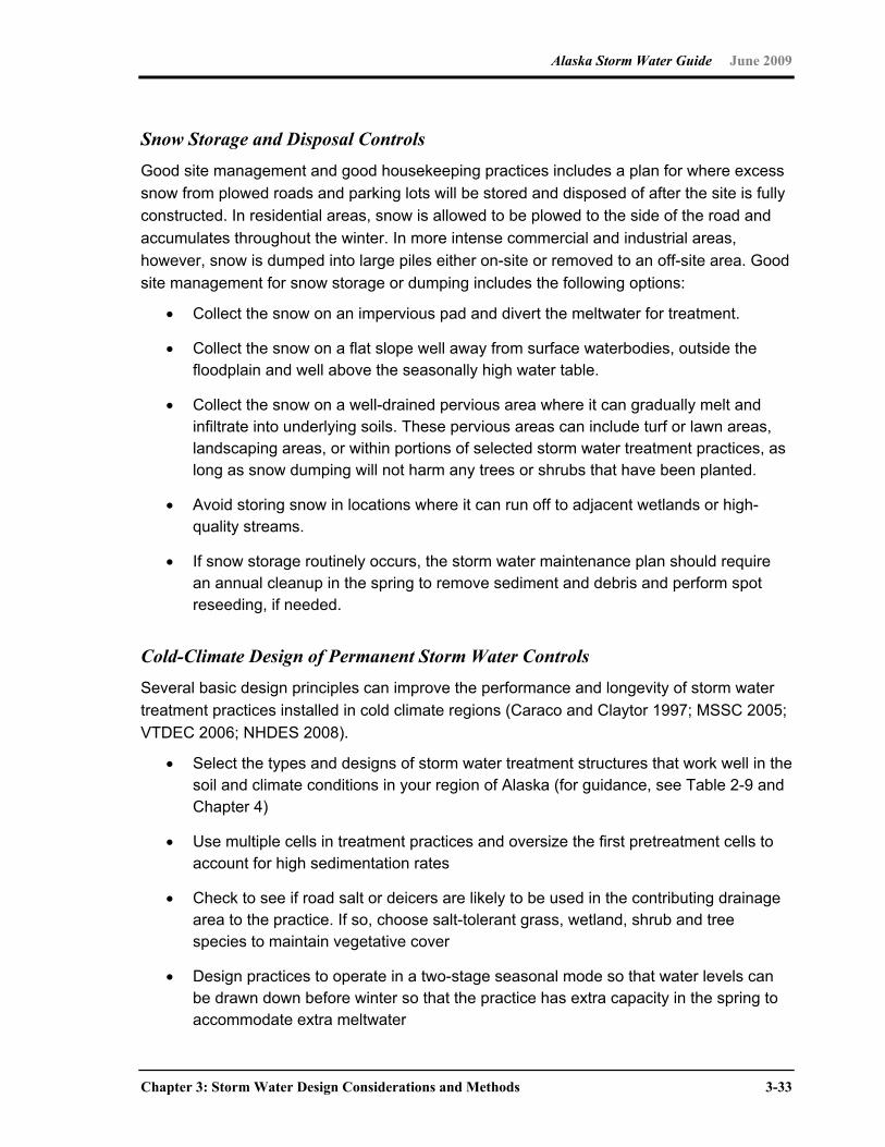
Alaska Storm Water Guide June 2009
Chapter 3: Storm Water Design Considerations and Methods 3-33
Snow Storage and Disposal Controls Good site management and good housekeeping practices includes a plan for where excess
snow from plowed roads and parking lots will be stored and disposed of after the site is fully
constructed. In residential areas, snow is allowed to be plowed to the side of the road and
accumulates throughout the winter. In more intense commercial and industrial areas,
however, snow is dumped into large piles either on-site or removed to an off-site area. Good
site management for snow storage or dumping includes the following options:
Collect the snow on an impervious pad and divert the meltwater for treatment.
Collect the snow on a flat slope well away from surface waterbodies, outside the floodplain and well above the seasonally high water table.
Collect the snow on a well-drained pervious area where it can gradually melt and infiltrate into underlying soils. These pervious areas can include turf or lawn areas, landscaping areas, or within portions of selected storm water treatment practices, as long as snow dumping will not harm any trees or shrubs that have been planted.
Avoid storing snow in locations where it can run off to adjacent wetlands or high-quality streams.
If snow storage routinely occurs, the storm water maintenance plan should require an annual cleanup in the spring to remove sediment and debris and perform spot reseeding, if needed.
Cold-Climate Design of Permanent Storm Water Controls Several basic design principles can improve the performance and longevity of storm water
treatment practices installed in cold climate regions (Caraco and Claytor 1997; MSSC 2005;
VTDEC 2006; NHDES 2008).
Select the types and designs of storm water treatment structures that work well in the soil and climate conditions in your region of Alaska (for guidance, see Table 2-9 and Chapter 4)
Use multiple cells in treatment practices and oversize the first pretreatment cells to account for high sedimentation rates
Check to see if road salt or deicers are likely to be used in the contributing drainage area to the practice. If so, choose salt-tolerant grass, wetland, shrub and tree species to maintain vegetative cover
Design practices to operate in a two-stage seasonal mode so that water levels can be drawn down before winter so that the practice has extra capacity in the spring to accommodate extra meltwater
Alaska Storm Water Guide June 2009
3-34 Chapter 3: Storm Water Design Considerations and Methods
Avoid draining ponds during the spring because temperature stratification and high chloride levels can discharge acidic or anoxic water downstream
Do not submerge inlet pipes into permanent pools to avoid causing pipe ice blockages that could damage pipes or cause upstream flooding
Slope inlet pipes so that they have a minimum slope of 1 or 2 percent to prevent standing water that could freeze
Avoid infiltration where permafrost exists
Place underdrains and outlet pipes at least a foot below the frost line, and increase their diameter by at least one pipe schedule
When perforated pipes are used, the minimum opening diameter should be one-half inch, and they should have a minimum pipe diameter of at least 6 inches
Angle trash racks to prevent ice formation
Modify maintenance agreements to specify an annual springtime maintenance inspection of storm water practices to assess whether cleanups or repairs are needed to maintain their function
Soil or sand filter beds should extend below the frost line, and in general, avoid using peat and organic media because they retain water and are likely to freeze
Use broad, multiple cell swales for surface treatment rather than underground pipes
Use the zero-order drainage network as a prime location for shallow, multi-cell, forested wetlands (CSN 2009)
More specific design guidance is provided for individual storm water treatment practices in
Chapter 5 of this manual.
3.4.6 Pulling It All Together: Choices in Local Storm Water Design Manuals
The statewide storm water manual presents a broad framework for making the best possible
storm water decisions, but localities will still need to make careful choices on how to adapt
and interpret this framework in the context of their local climate, terrain and development
conditions. In addition, localities will need to provide more detail on how storm water will be
handled in their local development review process, including measures for design submittal,
construction inspection, facility acceptance and maintenance. An excellent resource for
developing local storm water guidance is in Managing Stormwater in Your Community: A
Guide for Building an Effective Post-Construction Program (Hirschman and Kosco 2008).
Alaska Storm Water Guide June 2009
Chapter 3: Storm Water Design Considerations and Methods 3-35
These choices can then be incorporated into local storm water ordinances, policies and
design guidance. The following checklist outlines some of the specific decisions that Alaska
communities need to make when building their local storm water programs:
Analyze local, long-term rainfall and snowmelt data
Define your local sizing criteria for the water quality volume and other storm events
Define the calendar dates by which special winter construction and ESCs will be required
Determine the range of acceptable storm water treatment practices
Define any cold-weather modifications for standard storm water and ESC practices
Determine whether your community will need to include special criteria for rural or redevelopment projects that might occur in the future
Determine if any additional land uses or future operations will be designated as storm water hotspots
Define the stages in local land development review process that storm water plans must be considered (e.g., initial concept plans, final engineering plans and any required coordination with other local or state environmental permits)
Determine standard submittal requirements and develop plan review, construction and maintenance checklists to streamline project review
Determine the model for maintenance responsibility in the community (public, private or hybrid) and minimum requirements for BMP tracking and inspection
Develop standard storm water easements, maintenance agreements, performance bonds and impervious cover mitigation fees
Encourage LID

This page intentionally left blank
Alaska Storm Water Guide June 2009
Chapter 4: Temporary Storm Water Controls 4-1
Chapter 4 Temporary Storm Water Controls
4.0 Introduction
This chapter focuses on temporary controls to address pollutants during active construction.
Temporary controls include practices installed at active construction sites such as erosion
and sediment controls (ESCs) (e.g., silt fence) or good housekeeping controls (e.g.,
concrete washouts). Temporary construction-phase storm water controls are typically
described in a storm water pollution prevention plan (SWPPP) that is required for most sites
disturbing greater than one acre.
Uncontrolled sediment from active construction sites can significantly affect receiving
waters. However, construction site operators with a basic understanding of ESC principles
(described in Section 4.1) can develop an effective SWPPP (described in Section 4.2) to
address construction-phase storm water problems. The key components of an effective
SWPPP are ESC best management practices (BMPs) (Section 4.3), good housekeeping
BMPs (Section 4.4), and appropriate inspection, maintenance and recordkeeping
procedures (Section 4.5). To help construction project designers avoid making the same
mistakes, a list of common problems with SWPPPs and temporary BMPs is also included
(Section 4.6).
4.1 Erosion and Sediment Control (ESC) Principles
To effectively address storm water runoff from construction sites, a basic understanding of
ESC principles is needed. ESC practices fall into three major classes: erosion prevention,
erosion control, and sediment control (MOA 2007). These three classes are discussed in
more detail below.

Alaska Storm Water Guide June 2009
4-2 Chapter 4: Temporary Storm Water Controls
Erosion Prevention Erosion prevention is any means used to keep soil particles in place. Erosion prevention is
the least expensive option of all ESC practices and should be the first line of defense
employed. Many erosion prevention efforts can occur without physically modifying a site,
and include planning, training, scheduling, sequencing and land management practices. The
easiest and most cost-effective erosion prevention measure is to minimize the area of
disturbance and retain existing vegetation.
Erosion Control Erosion control is a practical complement to the exclusive use of erosion prevention, and
should be the primary ESC practice employed on construction sites. In its simplest form,
erosion control consists of preventing soils in construction areas from moving downslope.
Erosion control minimizes the forces from raindrops, concentrated runoff flows, and wind,
each of which detach and transport soil particles. Erosion controls treat the soil as a valued
resource that must be conserved in place. Current literature on erosion control promotes
several key concepts:
Minimize areas of disturbance—Undisturbed natural vegetation is the best inhibitor
of erosion. The time it takes for erosion rates of areas disturbed by construction and
subsequently revegetated to return to pre-construction rates varies considerably
across Alaska because of the wide range of conditions present.
Cover and stabilize disturbed areas as soon as possible—Any efforts to quickly
cover areas of disturbance are rewarded with reduced soil erosion.
Sequence and schedule construction to take advantage of drier weather patterns—Proper sequencing and scheduling of construction offers many benefits,
such as reduced ESC costs, quicker reestablishment of vegetation, and protection of
the environment.
Divert runoff around erodible areas—Measures that keep flow from traversing
disturbed areas reduce the need for additional sediment control efforts. Diversion
ditches and benching are effective means of routing runoff away from erodible
surfaces. To prevent erosion of the diversion channels themselves, ensure that they
are lined.
Reduce runoff quantities and velocities—Keeping runoff velocities low offers
significant savings in ESC. The doubling of runoff velocity theoretically results a 64-
fold increase in the size of a particle that can be transported. Appropriately designed
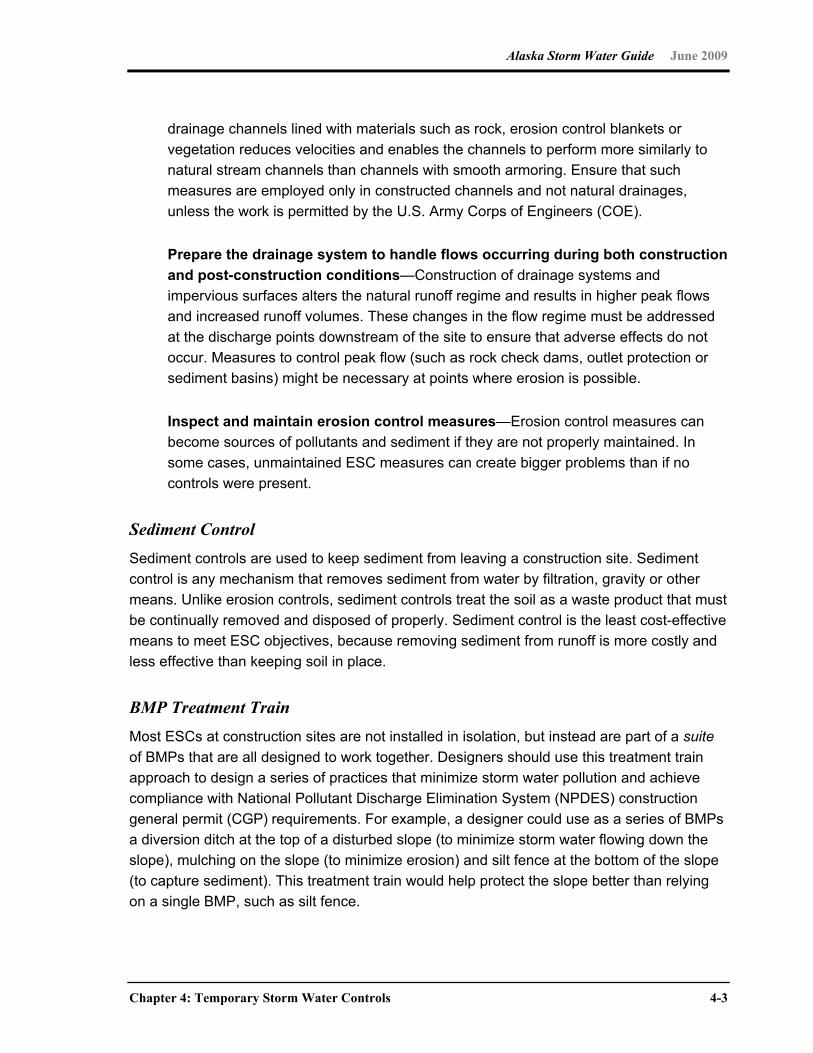
Alaska Storm Water Guide June 2009
Chapter 4: Temporary Storm Water Controls 4-3
drainage channels lined with materials such as rock, erosion control blankets or
vegetation reduces velocities and enables the channels to perform more similarly to
natural stream channels than channels with smooth armoring. Ensure that such
measures are employed only in constructed channels and not natural drainages,
unless the work is permitted by the U.S. Army Corps of Engineers (COE).
Prepare the drainage system to handle flows occurring during both construction and post-construction conditions—Construction of drainage systems and
impervious surfaces alters the natural runoff regime and results in higher peak flows
and increased runoff volumes. These changes in the flow regime must be addressed
at the discharge points downstream of the site to ensure that adverse effects do not
occur. Measures to control peak flow (such as rock check dams, outlet protection or
sediment basins) might be necessary at points where erosion is possible.
Inspect and maintain erosion control measures—Erosion control measures can
become sources of pollutants and sediment if they are not properly maintained. In
some cases, unmaintained ESC measures can create bigger problems than if no
controls were present.
Sediment Control Sediment controls are used to keep sediment from leaving a construction site. Sediment
control is any mechanism that removes sediment from water by filtration, gravity or other
means. Unlike erosion controls, sediment controls treat the soil as a waste product that must
be continually removed and disposed of properly. Sediment control is the least cost-effective
means to meet ESC objectives, because removing sediment from runoff is more costly and
less effective than keeping soil in place.
BMP Treatment Train Most ESCs at construction sites are not installed in isolation, but instead are part of a suite
of BMPs that are all designed to work together. Designers should use this treatment train
approach to design a series of practices that minimize storm water pollution and achieve
compliance with National Pollutant Discharge Elimination System (NPDES) construction
general permit (CGP) requirements. For example, a designer could use as a series of BMPs
a diversion ditch at the top of a disturbed slope (to minimize storm water flowing down the
slope), mulching on the slope (to minimize erosion) and silt fence at the bottom of the slope
(to capture sediment). This treatment train would help protect the slope better than relying
on a single BMP, such as silt fence.
Alaska Storm Water Guide June 2009
4-4 Chapter 4: Temporary Storm Water Controls
Keys to Effective ESC The following list presents 10 key principles (USEPA 2007) in the control of erosion and
sediment at construction sites. Construction operators should ensure that their SWPPP
includes BMPs to address each of these principles where they apply.
Principles 1–5: Erosion Prevention and Erosion Control (keeping the dirt in place)
ESC Principle 1: Minimize disturbed area and protect natural features and soil. As an
SWPPP is developed, carefully consider the natural features of the site. Delineate and
control the area that will be disturbed by grading or construction activities to reduce the
potential for soil erosion and storm water pollution problems. Limit disturbed areas to only
those necessary for the construction project. Natural vegetation is the best and cheapest
erosion control BMP.
Protecting and preserving topsoil is also a good BMP. Removing topsoil exposes underlying
layers that are often more prone to erosion and have less infiltration capacity. Keeping
topsoil in place preserves the natural structure of the soils and aids the infiltration of storm
water. Preservation of topsoil should not be used alone. However, it should be combined
with other ESCs to prevent erosion of the topsoil itself.
ESC Principle 2: Phase construction activity. Another technique for minimizing the
duration of exposed soil is phasing. Schedule or sequence construction work and
concentrate it in certain areas to minimize the amount of soil that is exposed to the elements
at a time. Limiting the area of disturbance to places where construction activities are
underway and stabilizing them as quickly as possible can be one of the most effective
BMPs. In climates with frozen soils, excavation work could be scheduled for winter although
ESCs will need to be in place before spring break-up.
ESC Principle 3: Control storm water flowing onto and through the project. Plan for
any potential storm water, surface water or groundwater flows coming onto the project area
from upstream locations, and divert (and slow) flows to prevent erosion. Likewise, the
location, volume and velocity of on-site storm water runoff should be controlled to minimize
soil erosion.
ESC Principle 4: Stabilize soils promptly. Stabilize exposed soils to minimize erosion
where construction activities have temporarily or permanently ceased. Stabilization
measures should be in place after grading activities have ceased. The CGP that is
applicable in Alaska requires stabilization within 14 days in portions of the site where
construction activities have ceased. Where stabilization by the 14th day is precluded by snow
cover or frozen ground conditions, stabilization measures must be initiated as soon as
Alaska Storm Water Guide June 2009
Chapter 4: Temporary Storm Water Controls 4-5
practicable. Provide either temporary or permanent cover to protect exposed soils.
Temporary measures are necessary when an area of a site is disturbed but where activities
in that area are not completed or until permanent BMPs are established. Topsoil stockpiles
should also be protected to minimize any erosion from these areas. Temporary-cover BMPs
include temporary seeding, mulches, matrices, blankets and mats, and the use of soil
binders or tackifiers (there might be additional state and local requirements for using
chemical-based soil binders). Permanent-cover BMPs include permanent seeding and
planting, sodding, channel stabilization and vegetative buffer strips. Silt fence and other
sediment control measures are not stabilization measures.
ESC Principle 5: Protect slopes. Protect all slopes with appropriate erosion controls.
Steeper slopes, slopes with highly erodible soils or long slopes require a more complex
combination of controls. Erosion control blankets, bonded fiber matrices or turf
reinforcement mats can be very effective options. Terracing, including the use of silt fence or
fiber rolls as terraces can be effective to help control erosion on moderate slopes and
should be installed on level contours spaced at 10- to 20-foot intervals. Also, use diversion
channels and berms to keep storm water off slopes.
Principles 6–10: Sediment Controls (the second line of defense)
ESC Principle 6: Protect storm drain inlets. Protect all inlets that could receive storm
water from the project until final stabilization of the site has been achieved. Install inlet
protection before soil-disturbing activities begin. Maintenance throughout the construction
process is important. Upon completion of the project, storm drain inlet protection is one of
the temporary BMPs that should be removed. Storm drain inlet protection should be used
not only for storm drains within the active construction area, but also for storm drains outside
the area that might receive storm water discharges from the project. If there are storm drains
on private property that could receive storm water runoff from the project, coordinate with
the owners of that property to ensure proper inlet protection.
ESC Principle 7: Establish perimeter controls. Maintain natural areas around the
project’s perimeter and supplement them with silt fence and fiber rolls around the perimeter
of the site to help prevent soil erosion and stop sediment from leaving the site. Install these
controls on the downslope perimeter of projects (it is often unnecessary to surround the
entire site with silt fence). Sediment barriers can be used to protect stream buffers, riparian
areas, wetlands, or other waterways. They are effective only in small areas and should not
be used in areas of concentrated flow. Do not install silt fences so that they run downslope
(which channels and concentrate flow) or cross areas of concentrated flow.
Alaska Storm Water Guide June 2009
4-6 Chapter 4: Temporary Storm Water Controls
ESC Principle 8: Retain sediment on-site and control dewatering practices. Sediment
barriers described in ESC Principle 7 can trap sediment from small areas, but when
sediment retention from a larger area is required, consider using a temporary sediment trap
or sediment basin. Such practices detain sediment-laden runoff for a period of time, allowing
sediment to settle before the runoff is discharged. Proper design and maintenance are
essential to ensure that the practices are effective.
Use a sediment basin for common drainage locations that serve an area with 10 or more
acres disturbed at a time. The basin should be designed to provide storage for the volume of
runoff from the drainage area for at least a 2-year, 24-hour storm (or 3,600 cubic feet of
storage per acre drained, which is enough to contain 1 inch of runoff, if the 2-year, 24-hour
calculation has not been performed). For more information, see Part 3.1.A of the U.S.
Environmental Protection Agency’s (EPA’s) 2008 CGP. Sediment basins should be in low-
lying areas of the site and on the downgradient side of bare soil areas where flows
converge. Do not put sediment traps or basins in or adjacent to flowing streams or other
waterways.
Where a large sediment basin is not practical, use smaller sediment basins or sediment
traps (or both) where feasible. At a minimum, use silt fences, vegetative buffer strips or
equivalent sediment controls for all downgradient boundaries (and for those side-slope
boundaries deemed appropriate for individual site conditions).
Dewatering practices are used to remove groundwater or accumulated rain water from
excavated areas. Pump muddy water from these areas to a temporary or permanent
sedimentation basin or to an area completely enclosed by silt fence in a flat, vegetated area
where discharges can infiltrate the ground. Alternatively, try to conduct excavation when
groundwater levels are lower to reduce or eliminate the need for dewatering.
If possible, pump clean groundwater out of the area to be excavated before disturbance
occurs, so discharges contain less sediment.
Never discharge muddy water into storm drains, streams, lakes, or wetlands.
ESC Principle 9: Establish stabilized construction exits. Vehicles entering and leaving
the site have the potential to track significant amounts of sediment onto streets where wind
or rain can convey it into storm drains. Identify and clearly mark one or two locations where
vehicles will enter and exit the site and focus stabilizing measures at those locations.
Construction entrances are commonly made from large crushed rock. They can be further
stabilized using stone pads or concrete. Also, steel wash racks and a hose-down system will
remove even more mud and debris from vehicle tires. Divert runoff from wash areas to a
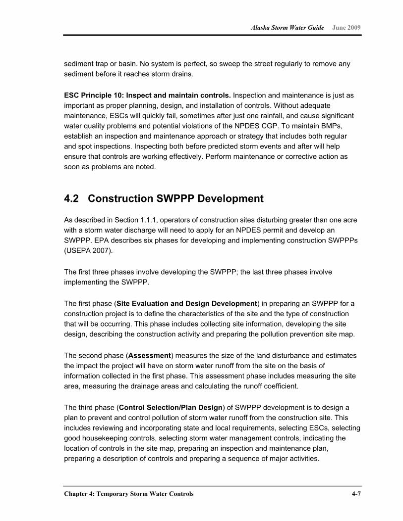
Alaska Storm Water Guide June 2009
Chapter 4: Temporary Storm Water Controls 4-7
sediment trap or basin. No system is perfect, so sweep the street regularly to remove any
sediment before it reaches storm drains.
ESC Principle 10: Inspect and maintain controls. Inspection and maintenance is just as
important as proper planning, design, and installation of controls. Without adequate
maintenance, ESCs will quickly fail, sometimes after just one rainfall, and cause significant
water quality problems and potential violations of the NPDES CGP. To maintain BMPs,
establish an inspection and maintenance approach or strategy that includes both regular
and spot inspections. Inspecting both before predicted storm events and after will help
ensure that controls are working effectively. Perform maintenance or corrective action as
soon as problems are noted.
4.2 Construction SWPPP Development
As described in Section 1.1.1, operators of construction sites disturbing greater than one acre
with a storm water discharge will need to apply for an NPDES permit and develop an
SWPPP. EPA describes six phases for developing and implementing construction SWPPPs
(USEPA 2007).
The first three phases involve developing the SWPPP; the last three phases involve
implementing the SWPPP.
The first phase (Site Evaluation and Design Development) in preparing an SWPPP for a
construction project is to define the characteristics of the site and the type of construction
that will be occurring. This phase includes collecting site information, developing the site
design, describing the construction activity and preparing the pollution prevention site map.
The second phase (Assessment) measures the size of the land disturbance and estimates
the impact the project will have on storm water runoff from the site on the basis of
information collected in the first phase. This assessment phase includes measuring the site
area, measuring the drainage areas and calculating the runoff coefficient.
The third phase (Control Selection/Plan Design) of SWPPP development is to design a
plan to prevent and control pollution of storm water runoff from the construction site. This
includes reviewing and incorporating state and local requirements, selecting ESCs, selecting
good housekeeping controls, selecting storm water management controls, indicating the
location of controls in the site map, preparing an inspection and maintenance plan,
preparing a description of controls and preparing a sequence of major activities.
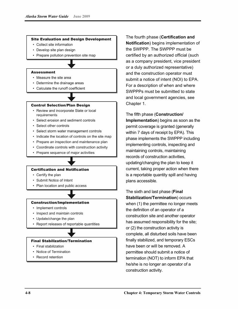
Alaska Storm Water Guide June 2009
4-8 Chapter 4: Temporary Storm Water Controls
The fourth phase (Certification and Notification) begins implementation of
the SWPPP. The SWPPP must be
certified by an authorized official (such
as a company president, vice president
or a duly authorized representative)
and the construction operator must
submit a notice of intent (NOI) to EPA.
For a description of when and where
SWPPPs must be submitted to state
and local government agencies, see
Chapter 1.
The fifth phase (Construction/ Implementation) begins as soon as the
permit coverage is granted (generally
within 7 days of receipt by EPA). This
phase implements the SWPPP including
implementing controls, inspecting and
maintaining controls, maintaining
records of construction activities,
updating/changing the plan to keep it
current, taking proper action when there
is a reportable quantity spill and having
plans accessible.
The sixth and last phase (Final Stabilization/Termination) occurs
when (1) the permittee no longer meets
the definition of an operator of a
construction site and another operator
has assumed responsibility for the site;
or (2) the construction activity is
complete, all disturbed soils have been
finally stabilized, and temporary ESCs
have been or wiII be removed. A
permittee should submit a notice of
termination (NOT) to inform EPA that
he/she is no longer an operator of a
construction activity.
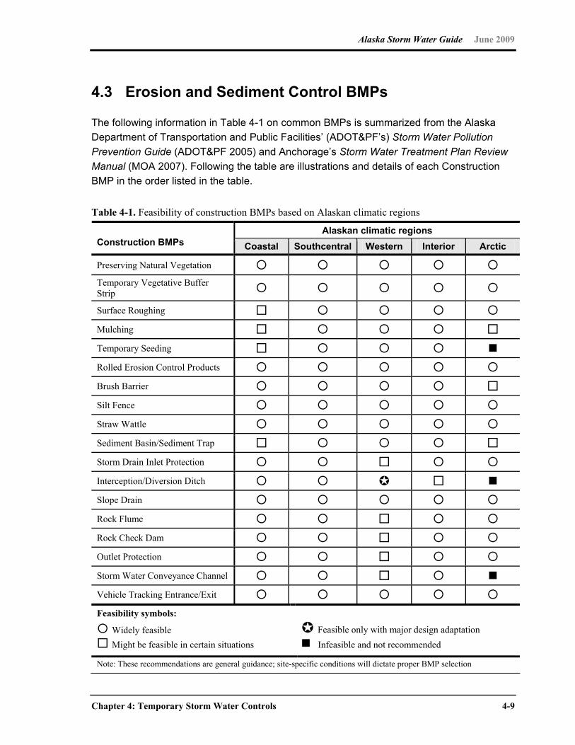
Alaska Storm Water Guide June 2009
Chapter 4: Temporary Storm Water Controls 4-9
4.3 Erosion and Sediment Control BMPs
The following information in Table 4-1 on common BMPs is summarized from the Alaska
Department of Transportation and Public Facilities’ (ADOT&PF’s) Storm Water Pollution
Prevention Guide (ADOT&PF 2005) and Anchorage’s Storm Water Treatment Plan Review
Manual (MOA 2007). Following the table are illustrations and details of each Construction
BMP in the order listed in the table.
Table 4-1. Feasibility of construction BMPs based on Alaskan climatic regions
Alaskan climatic regions Construction BMPs Coastal Southcentral Western Interior Arctic
Preserving Natural Vegetation Temporary Vegetative Buffer Strip
Surface Roughing Mulching Temporary Seeding Rolled Erosion Control Products Brush Barrier Silt Fence Straw Wattle Sediment Basin/Sediment Trap Storm Drain Inlet Protection Interception/Diversion Ditch Slope Drain Rock Flume Rock Check Dam Outlet Protection Storm Water Conveyance Channel Vehicle Tracking Entrance/Exit Feasibility symbols:
Widely feasible Might be feasible in certain situations
Feasible only with major design adaptation Infeasible and not recommended
Note: These recommendations are general guidance; site-specific conditions will dictate proper BMP selection
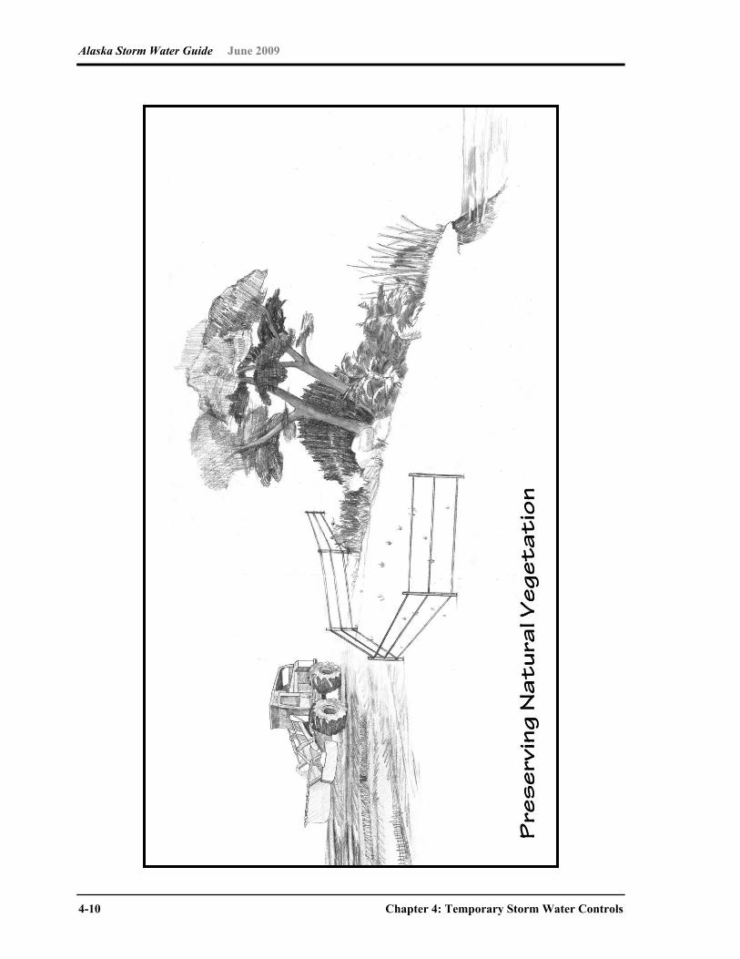
Alaska Storm Water Guide June 2009
4-10 Chapter 4: Temporary Storm Water Controls
Alaska Storm Water Guide June 2009
Chapter 4: Temporary Storm Water Controls 4-11
Preserving Natural Vegetation
Alaskan climatic regions Construction BMP Coastal Southcentral Western Interior Arctic
Preserving Natural Vegetation Feasibility
Description The principal advantage of preserving natural vegetation is protecting desirable trees, vines, bushes and grasses from damage during project development. Vegetation provides erosion control, storm water detention, biofiltration and aesthetic values to a site during and after construction activities. Any existing vegetation should be saved unless it is determined to be invasive or otherwise harmful.
Selection Designers should be aware of and respond to local climate and other conditions, including project scheduling, that might influence the use of natural vegetative stabilization measures. Before clearing activities begin, clearly mark the vegetation that is to be preserved. Prepare a site map with the locations of trees and boundaries of environmentally sensitive areas and buffer zones to be preserved. Plan the location of roads, buildings and other structures to avoid these areas. This requires careful site management to minimize the impact of construction activities on existing vegetation. Protect large trees near construction zones because damage during construction activities could result in reduced vigor or death after construction has ceased. Extend and mark the boundaries around contiguous natural areas and tree drip lines to protect the root zone from damage.
Maintenance Even if workers take precautions, some damage to protected areas might occur. If this happens, repair or replace damaged vegetation immediately to maintain the integrity of the natural system. When planning for new vegetation, choose kinds that enhance the existing vegetation. Ensure that new structures do not harm protected areas.
Feasibility symbols:
Widely feasible Might be feasible in certain situations
Feasible only with major design adaptation Infeasible and not recommended
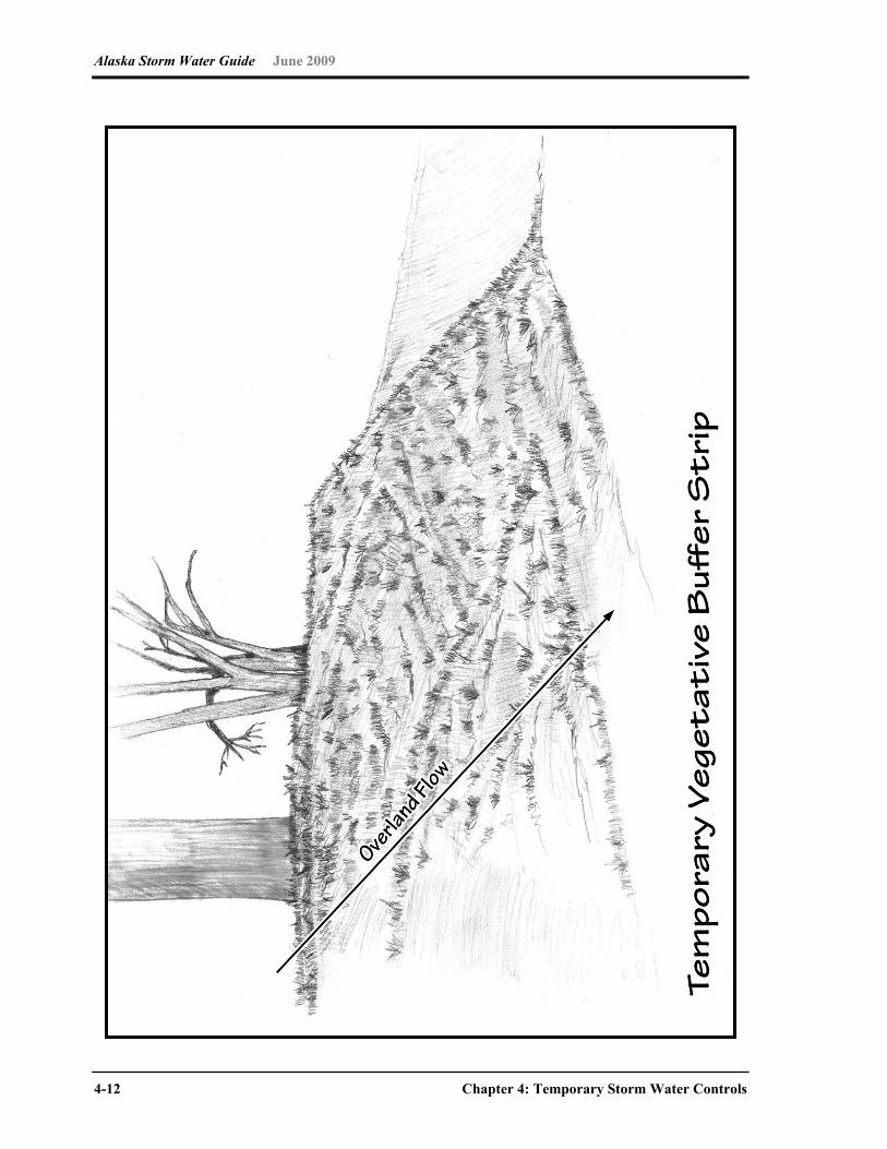
Alaska Storm Water Guide June 2009
4-12 Chapter 4: Temporary Storm Water Controls
Alaska Storm Water Guide June 2009
Chapter 4: Temporary Storm Water Controls 4-13
Temporary Vegetative Buffer Strip
Alaskan climatic regions Construction BMP Coastal Southcentral Western Interior Arctic
Temporary Vegetative Buffer Strip Feasibility
Description Temporary vegetated buffer strips are areas of natural or established vegetation maintained to protect the water quality of neighboring areas. Buffer strips slow storm water runoff, provide an area where runoff can permeate the soil, contribute to groundwater recharge and filter sediment. Slowing runoff also helps to prevent soil erosion and streambank collapse.
Selection Temporary vegetated buffers can be used in any area able to support vegetation. They are most effective and beneficial on floodplains, near wetlands, along streambanks and on unstable slopes. Jurisdictional wetlands cannot be used as vegetated buffer strips unless permitted by the COE.
Implementation Make sure soils are not compacted. Make sure slopes are less than 5 percent unless temporary erosion
control mats are also used. Determine buffer widths after carefully considering slope,
vegetation, soils, depth to impermeable layers, runoff sediment characteristics, type and amount of pollutants, and annual rainfall.
Make sure buffer widths increase as slope increases. Intermix zones of vegetation (native vegetation in particular),
including grasses, deciduous and evergreen shrubs, and understory and overstory trees.
In areas where flows are concentrated and fast, combine buffer zones with other practices such as level spreaders, infiltration areas or diversions to prevent erosion and rilling.
Maintenance Keeping vegetation healthy in temporary vegetated buffers requires routine maintenance. Depending on species, soil types, and climatic conditions, maintenance can include weed and pest control, mowing, fertilizing, liming, irrigating and pruning. Inspection and maintenance are most important when buffer areas are first installed. Once established, vegetated buffers do not require maintenance beyond the routine procedures and periodic inspections.
Feasibility symbols:
Widely feasible Might be feasible in certain situations
Feasible only with major design adaptation Infeasible and not recommended
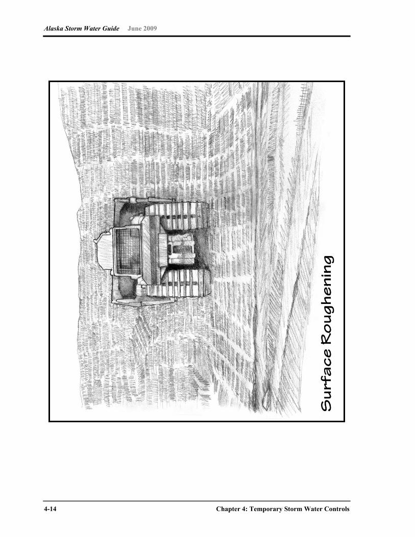
Alaska Storm Water Guide June 2009
4-14 Chapter 4: Temporary Storm Water Controls
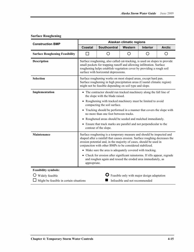
Alaska Storm Water Guide June 2009
Chapter 4: Temporary Storm Water Controls 4-15
Surface Roughening
Alaskan climatic regions Construction BMP Coastal Southcentral Western Interior Arctic
Surface Roughening Feasibility
Description Surface roughening, also called cat-tracking, is used on slopes to provide small pockets for trapping runoff and allowing infiltration. Surface roughening helps establish vegetation cover by providing a rough soil surface with horizontal depressions.
Selection Surface roughening works on most sloped areas, except hard pan. Surface roughening in high precipitation areas (Coastal climatic region) might not be feasible depending on soil type and slope.
Implementation The contractor should run tracked machinery along the fall line of the slope with the blade raised.
Roughening with tracked machinery must be limited to avoid compacting the soil surface.
Tracking should be performed in a manner that covers the slope with no more than one foot between tracks.
Roughened areas should be seeded and mulched immediately. Ensure that track marks are parallel and not perpendicular to the
contour of the slope.
Maintenance Surface roughening is a temporary measure and should be inspected and shaped after a rainfall that causes erosion. Surface roughing decreases the erosion potential and, in the majority of cases, should be used in conjunction with other BMPs to be considered stabilized. Make sure the area is adequately covered with tracking. Check for erosion after significant rainstorms. If rills appear, regrade
and roughen again and reseed the eroded area immediately, as appropriate.
Feasibility symbols:
Widely feasible Might be feasible in certain situations
Feasible only with major design adaptation Infeasible and not recommended
Alaska Storm Water Guide June 2009
4-16 Chapter 4: Temporary Storm Water Controls
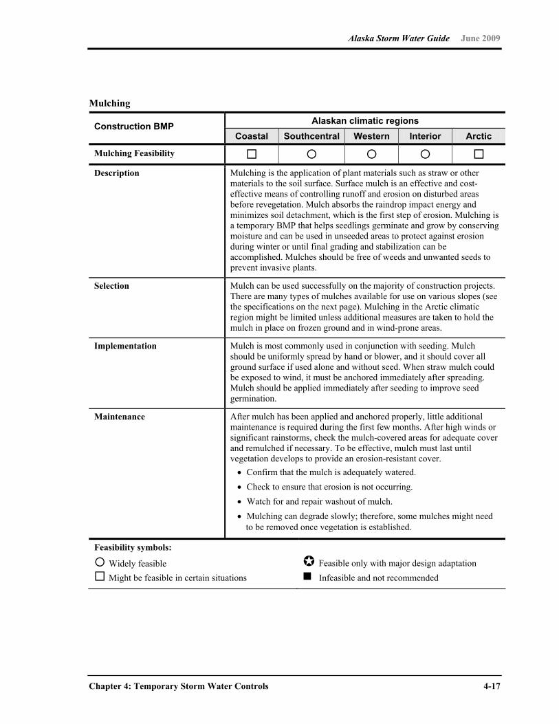
Alaska Storm Water Guide June 2009
Chapter 4: Temporary Storm Water Controls 4-17
Mulching
Alaskan climatic regions Construction BMP Coastal Southcentral Western Interior Arctic
Mulching Feasibility Description Mulching is the application of plant materials such as straw or other
materials to the soil surface. Surface mulch is an effective and cost-effective means of controlling runoff and erosion on disturbed areas before revegetation. Mulch absorbs the raindrop impact energy and minimizes soil detachment, which is the first step of erosion. Mulching is a temporary BMP that helps seedlings germinate and grow by conserving moisture and can be used in unseeded areas to protect against erosion during winter or until final grading and stabilization can be accomplished. Mulches should be free of weeds and unwanted seeds to prevent invasive plants.
Selection Mulch can be used successfully on the majority of construction projects. There are many types of mulches available for use on various slopes (see the specifications on the next page). Mulching in the Arctic climatic region might be limited unless additional measures are taken to hold the mulch in place on frozen ground and in wind-prone areas.
Implementation Mulch is most commonly used in conjunction with seeding. Mulch should be uniformly spread by hand or blower, and it should cover all ground surface if used alone and without seed. When straw mulch could be exposed to wind, it must be anchored immediately after spreading. Mulch should be applied immediately after seeding to improve seed germination.
Maintenance After mulch has been applied and anchored properly, little additional maintenance is required during the first few months. After high winds or significant rainstorms, check the mulch-covered areas for adequate cover and remulched if necessary. To be effective, mulch must last until vegetation develops to provide an erosion-resistant cover. Confirm that the mulch is adequately watered. Check to ensure that erosion is not occurring. Watch for and repair washout of mulch. Mulching can degrade slowly; therefore, some mulches might need
to be removed once vegetation is established.
Feasibility symbols:
Widely feasible Might be feasible in certain situations
Feasible only with major design adaptation Infeasible and not recommended

Alaska Storm Water Guide June 2009
4-18 Chapter 4: Temporary Storm Water Controls
Mulching Specifications
Mulch type Characteristics Application
Straw Should be air dried, come from wheat or oats, and be free of weeds and coarse material.
Most commonly used in conjunction with seeding and where the need for protection is for shorter than 3 months.
Spread by hand or machine to a minimum 4 inches thick.
Anchor by crimping, disking, rolling, or punching into the soil, covering with netting or keeping moist.
Wood Chips Should be small enough to use as a mulching medium.
Suitable for areas that will not be closely mowed and around ornamental plantings.
Can be obtained from trees that were cleared from the site to provide inexpensive mulch.
Apply to slopes less than 6 percent (16:1) to avoid clogging of drainage inlets by chips washed downslope.
Bark Chips Should be small enough to use as a mulching medium.
Use in landscape plantings.
Use in areas to be planted with grasses and not closely mowed.
Apply by hand or mechanically.
Wood Fiber Cellulose (partially digested wood fibers)
Dyed green; should not contain growth-inhibiting factors.
Short cellulose fibers do not required tacking, but longer fiber lengths provide better erosion control.
Use in hydroseeding operations as part of the slurry.
Apply with hydromulcher: 25 to 30 pounds per 1,000 square feet.
Bonded Fiber Matrix Hydraulically applied fibers and adhesives that form an erosion resistant blanket
Biodegradable, promotes growth of vegetation
Apply hydraulically Typically applied at rates from
3,000 to 4,000 lb/acre Do not apply immediately
before, during or after rainfall
Flexible Growth Medium
Generally provides good protection
No cure time (can be applied under most conditions)
Hydraulically applied Typically applied at rates of
3,500 lb/acre

Alaska Storm Water Guide June 2009
Chapter 4: Temporary Storm Water Controls 4-19
This page intentionally left blank.
Alaska Storm Water Guide June 2009
4-20 Chapter 4: Temporary Storm Water Controls
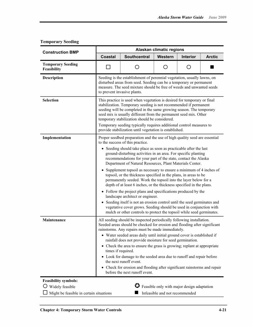
Alaska Storm Water Guide June 2009
Chapter 4: Temporary Storm Water Controls 4-21
Temporary Seeding
Alaskan climatic regions Construction BMP Coastal Southcentral Western Interior Arctic
Temporary Seeding Feasibility
Description Seeding is the establishment of perennial vegetation, usually lawns, on disturbed areas from seed. Seeding can be a temporary or permanent measure. The seed mixture should be free of weeds and unwanted seeds to prevent invasive plants.
Selection This practice is used when vegetation is desired for temporary or final stabilization. Temporary seeding is not recommended if permanent seeding will be completed in the same growing season. The temporary seed mix is usually different from the permanent seed mix. Other temporary stabilization should be considered. Temporary seeding typically requires additional control measures to provide stabilization until vegetation is established.
Implementation Proper seedbed preparation and the use of high quality seed are essential to the success of this practice. Seeding should take place as soon as practicable after the last
ground-disturbing activities in an area. For specific planting recommendations for your part of the state, contact the Alaska Department of Natural Resources, Plant Materials Center.
Supplement topsoil as necessary to ensure a minimum of 4 inches of topsoil, or the thickness specified in the plans, in areas to be permanently seeded. Work the topsoil into the layer below for a depth of at least 6 inches, or the thickness specified in the plans.
Follow the project plans and specifications produced by the landscape architect or engineer.
Seeding itself is not an erosion control until the seed germinates and vegetative cover grows. Seeding should be used in conjunction with mulch or other controls to protect the topsoil while seed germinates.
Maintenance All seeding should be inspected periodically following installation. Seeded areas should be checked for erosion and flooding after significant rainstorms. Any repairs must be made immediately. Water seeded areas daily until initial ground cover is established if
rainfall does not provide moisture for seed germination. Check the area to ensure the grass is growing; replant at appropriate
times if required. Look for damage to the seeded area due to runoff and repair before
the next runoff event. Check for erosion and flooding after significant rainstorms and repair
before the next runoff event.
Feasibility symbols: Widely feasible Might be feasible in certain situations
Feasible only with major design adaptation Infeasible and not recommended
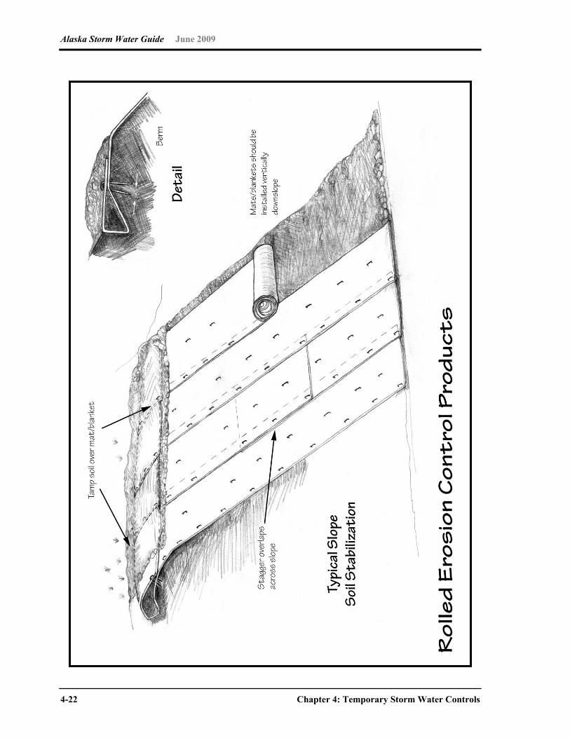
Alaska Storm Water Guide June 2009
4-22 Chapter 4: Temporary Storm Water Controls
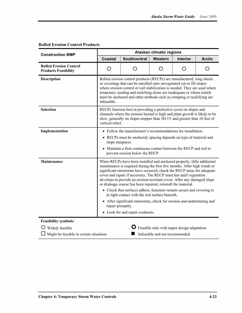
Alaska Storm Water Guide June 2009
Chapter 4: Temporary Storm Water Controls 4-23
Rolled Erosion Control Products
Alaskan climatic regions Construction BMP Coastal Southcentral Western Interior Arctic
Rolled Erosion Control Products Feasibility
Description Rolled erosion control products (RECPs) are manufactured, long sheets or coverings that can be unrolled onto unvegetated cut or fill slopes where erosion control or soil stabilization is needed. They are used where temporary seeding and mulching alone are inadequate or where mulch must be anchored and other methods such as crimping or tackifying are infeasible.
Selection RECPs function best in providing a protective cover on slopes and channels where the erosion hazard is high and plant growth is likely to be slow, generally on slopes stepper than 3H:1V and greater than 10 feet of vertical relief.
Implementation Follow the manufacturer’s recommendations for installation. RECPs must be anchored; spacing depends on type of material and
slope steepness. Maintain a firm continuous contact between the RECP and soil to
prevent erosion below the RECP.
Maintenance When RECPs have been installed and anchored properly, little additional maintenance is required during the first few months. After high winds or significant rainstorms have occurred, check the RECP areas for adequate cover and repair if necessary. The RECP must last until vegetation develops to provide an erosion-resistant cover. After any damaged slope or drainage course has been repaired, reinstall the material. Check that surfaces adhere, fasteners remain secure and covering is
in tight contact with the soil surface beneath. After significant rainstorms, check for erosion and undermining and
repair promptly. Look for and repair washouts.
Feasibility symbols:
Widely feasible Might be feasible in certain situations
Feasible only with major design adaptation Infeasible and not recommended
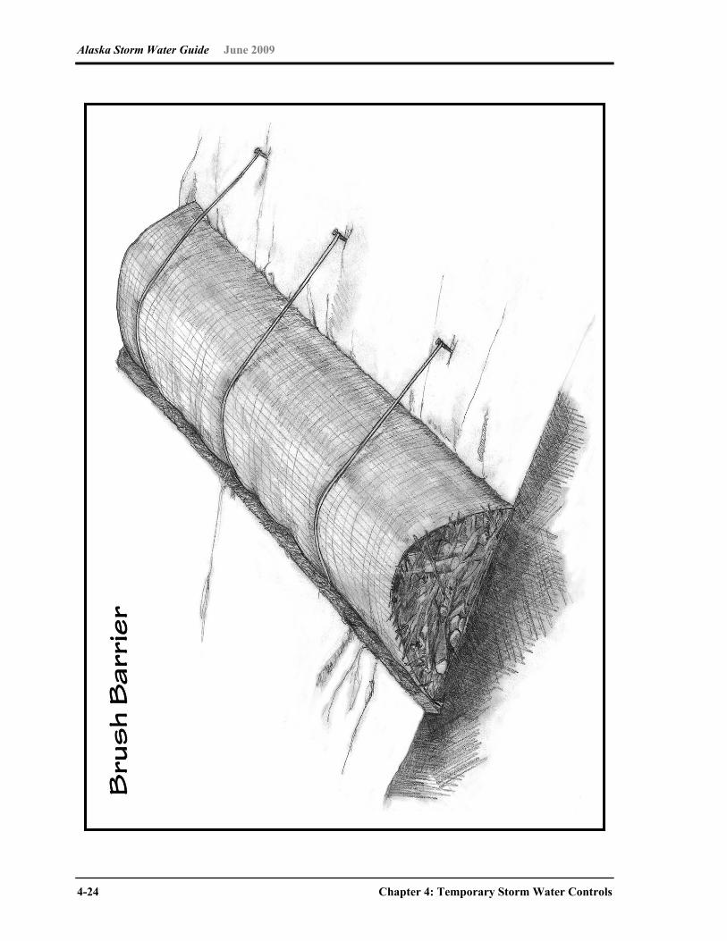
Alaska Storm Water Guide June 2009
4-24 Chapter 4: Temporary Storm Water Controls

Alaska Storm Water Guide June 2009
Chapter 4: Temporary Storm Water Controls 4-25
Brush Barrier
Alaskan climatic regions Construction BMP Coastal Southcentral Western Interior Arctic
Brush Barrier Feasibility Description Brush barriers are perimeter sediment control structures constructed of
material such as small tree branches, root mats, stone or other non-erodible debris left over from site clearing and grubbing. Brush barriers can be covered with a filter cloth to stabilize the structure and improve barrier efficiency.
Selection The drainage area for brush barriers must be no greater than 0.25 acre per 100 feet of barrier length. In addition, the drainage slope leading down to a brush barrier must be no greater than 2:1 and no longer than 100 feet. Brush barriers have limited usefulness because they are constructed of materials that decompose.
Implementation It is recommended that brush barriers be covered with a filter fabric barrier to hold the material in place and increase sediment barrier efficiency. The barrier mound should be at least 3 feet high and 5 feet wide at its base. Material with a diameter larger than 6 inches should not be used, because this material might be too bulky and create void spaces where sediment and runoff will flow through the barrier. The edge of the filter fabric cover should be buried in a trench 4 inches deep and 6 inches wide on the drainage side of the barrier. This is done to secure the fabric and create a barrier to sediment while allowing storm water to pass through the water-permeable filter fabric. The filter fabric should be extended just over the peak of the brush mound and secured on the down-slope edge of the fabric by fastening it to twine or small-diameter rope that is staked securely. Install the brush barrier parallel to the contour of the slope and without gaps that would allow runoff to bypass the barrier.
Maintenance Inspect brush barriers according to the schedule specified in the SWPPP to ensure their continued effectiveness. If channels form through void spaces, reconstruct the barrier to eliminate the channels. Accumulated sediment should be removed from the uphill side of the barrier when sediment height reaches between one-third and one-half the height of the barrier. When the entire site has reached final stabilization, remove the brush barrier and dispose of it properly.
Feasibility symbols:
Widely feasible Might be feasible in certain situations
Feasible only with major design adaptation Infeasible and not recommended
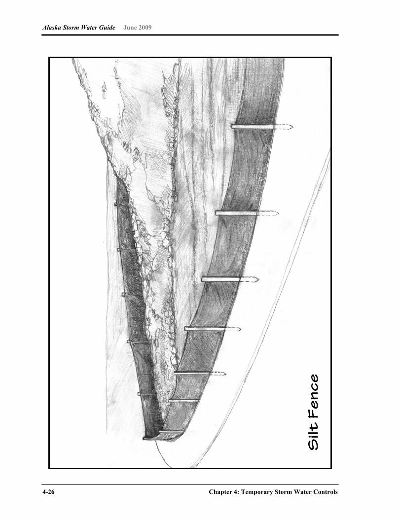
Alaska Storm Water Guide June 2009
4-26 Chapter 4: Temporary Storm Water Controls

Alaska Storm Water Guide June 2009
Chapter 4: Temporary Storm Water Controls 4-27
Silt Fence
Alaskan climatic regions Construction BMP Coastal Southcentral Western Interior Arctic
Silt Fence Feasibility Description Silt fences are used to pond sheet flow runoff on sloped areas, thus
allowing heavy sediment particles to settle out while water and lighter particles leak slowly through the fence material. The fences can be very effective in removing sediment from runoff.
Selection Silt fences are appropriate for the majority of construction sites that are not more than moderately sloped. The design life a silt fence is 6 months or less. The maximum contributory sheet flow drainage area should not exceed 0.25 acres per 100 feet of silt fence. Use of a silt fence is usually more complex, expensive, and maintenance-prone than other sediment control measures. Silt fence might not be the most appropriate control measure for uneven terrain or when vegetative mat contains high density of roots that preclude keying in the fabric.
Implementation Silt fences should be installed at right angles to the slope and along contours. Silt fences should be installed at the bottom of a slope or on a bench on a slope. Because of the difficulty of installing silt fence on frozen ground, installation should take place, where possible, before the ground freezes. Posts should be securely installed with the fabric attached to the uphill side of the post. The filter fabric should be securely attached to the posts. The filter fabric should be keyed into the surrounding earth. Silt fences should not be used in locations with concentrated flow, including streams or other storm water conveyances. Silt fence should only be used to contain sediment on-site.
Maintenance The filter fabric should be kept up to maintain its function. If it is torn or frayed, replace it. The posts should be reinstalled if loose. The filter fabric should be reinstalled if it is not keyed into the surrounding earth. The silt fence should be cleaned when sediment accumulates (see the most current CGP for specific requirements; the CGP specifies 50 percent of design capacity) and cleaned or replaced when it is covered with sediment. Confirm that the fence posts are secure. Assure that the filter fabric is securely attached to the fence posts. Look for and repair filter fabric that is torn or frayed. Check for evidence of runoff overtopping the filter fabric; correct as
necessary. Verify that the silt fence is not leaning over. Check for underflow and re-key if necessary. Remedy fence sags as needed.
Feasibility symbols:
Widely feasible Might be feasible in certain situations
Feasible only with major design adaptation Infeasible and not recommended

Alaska Storm Water Guide June 2009
4-28 Chapter 4: Temporary Storm Water Controls
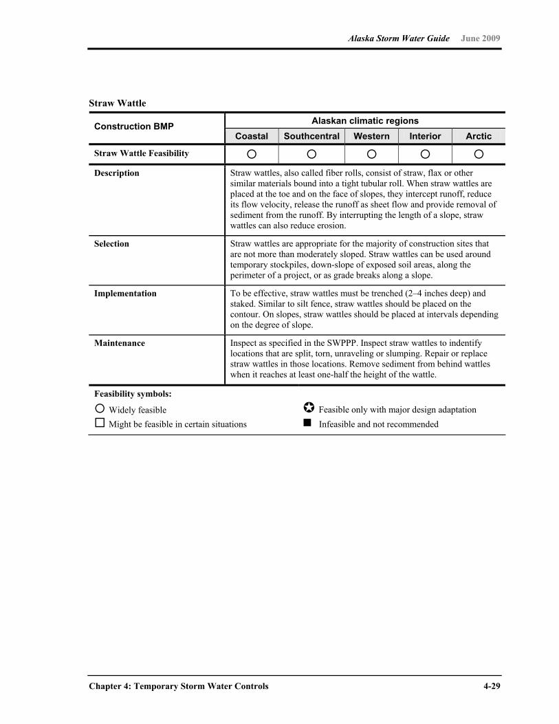
Alaska Storm Water Guide June 2009
Chapter 4: Temporary Storm Water Controls 4-29
Straw Wattle
Alaskan climatic regions Construction BMP Coastal Southcentral Western Interior Arctic
Straw Wattle Feasibility Description Straw wattles, also called fiber rolls, consist of straw, flax or other
similar materials bound into a tight tubular roll. When straw wattles are placed at the toe and on the face of slopes, they intercept runoff, reduce its flow velocity, release the runoff as sheet flow and provide removal of sediment from the runoff. By interrupting the length of a slope, straw wattles can also reduce erosion.
Selection Straw wattles are appropriate for the majority of construction sites that are not more than moderately sloped. Straw wattles can be used around temporary stockpiles, down-slope of exposed soil areas, along the perimeter of a project, or as grade breaks along a slope.
Implementation To be effective, straw wattles must be trenched (2–4 inches deep) and staked. Similar to silt fence, straw wattles should be placed on the contour. On slopes, straw wattles should be placed at intervals depending on the degree of slope.
Maintenance Inspect as specified in the SWPPP. Inspect straw wattles to indentify locations that are split, torn, unraveling or slumping. Repair or replace straw wattles in those locations. Remove sediment from behind wattles when it reaches at least one-half the height of the wattle.
Feasibility symbols:
Widely feasible Might be feasible in certain situations
Feasible only with major design adaptation Infeasible and not recommended
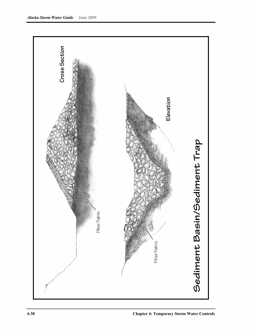
Alaska Storm Water Guide June 2009
4-30 Chapter 4: Temporary Storm Water Controls

Alaska Storm Water Guide June 2009
Chapter 4: Temporary Storm Water Controls 4-31
Sediment Basin/Sediment Trap
Alaskan climatic regions Construction BMP Coastal Southcentral Western Interior Arctic
Sediment Basin/Sediment Trap Feasibility
Description Sedimentation basins are used to remove large quantities of sediment from runoff. The basin can be designed to remove fine-grained sediments such as clays or silts as well as some chemicals. The basin can also serve an added function for runoff detention. A temporary sediment trap is a small temporary ponding area, with a rock outlet, formed by excavating below grade or by constructing an earth embankment or both. A sediment trap is a temporary structure that is used to detain runoff from small drainage areas so that sediment can settle out.
Selection Sedimentation basins are generally used on medium- to large-scale projects, and where sediment discharge would damage environmentally sensitive areas. Sediment traps generally are used for drainage areas less than 5 acres, and sediment basins are used for drainage areas greater than 5 acres. They should be in areas where access can be maintained for sediment removal and proper disposal. Sediment basins are required on construction site drainage areas that are 10 acres or larger, unless infeasible, in which case, equivalent smaller sediment traps must be used.
Implementation The sedimentation basin should be installed according to approved plans and specifications, or as required by the SWPPP. Because the facilities are customized for each project, the approved construction plans provide the best source of information on implementation. Sizing of the basins, at a minimum, should meet the EPA CGP requirement (storage for the volume of runoff from the drainage area for at least a 2-year, 24-hour storm).
Maintenance Sediment should be removed from the sedimentation basin yearly or when it accumulates to a depth of one foot, or as specified in the SWPPP. For the sediment trap, remove sediment and restore the trap to its original dimensions when the sediment has accumulated to one-half its design storage capacity. If sediment impairs the function of the outlet structure, clean the trap more frequently. Rocks and washed gravel should be cleaned or replaced when they become filled with sediment. Sediment basins should be maintained to prevent their becoming a pollutant source. If sloughing or erosion of side slopes occurs, repair the sedimentation basin. Confirm that the construction plans have been followed. Check that sediment accumulation is within acceptable limits. Confirm that the outlet structure is functioning properly. Confirm that sediment is not passing through to the downstream end. Check for accumulations of floating debris. Check to ensure that the emergency overflow spillway is not obstructed.
Feasibility symbols:
Widely feasible Might be feasible in certain situations
Feasible only with major design adaptation Infeasible and not recommended
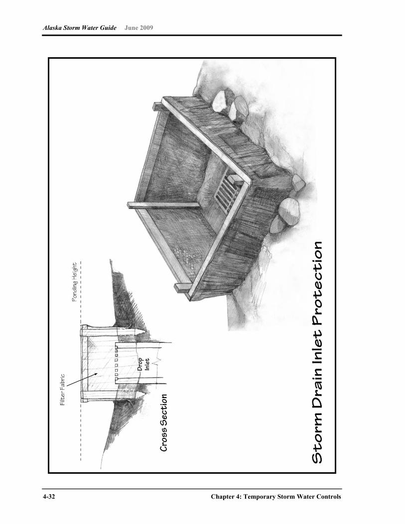
Alaska Storm Water Guide June 2009
4-32 Chapter 4: Temporary Storm Water Controls
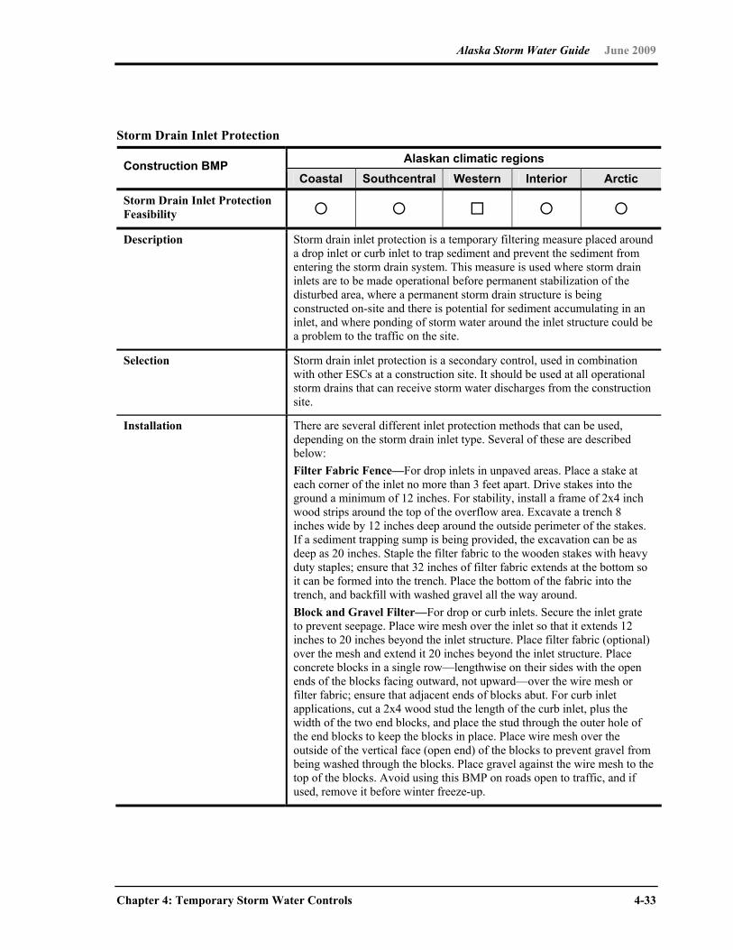
Alaska Storm Water Guide June 2009
Chapter 4: Temporary Storm Water Controls 4-33
Storm Drain Inlet Protection
Alaskan climatic regions Construction BMP Coastal Southcentral Western Interior Arctic
Storm Drain Inlet Protection Feasibility
Description Storm drain inlet protection is a temporary filtering measure placed around a drop inlet or curb inlet to trap sediment and prevent the sediment from entering the storm drain system. This measure is used where storm drain inlets are to be made operational before permanent stabilization of the disturbed area, where a permanent storm drain structure is being constructed on-site and there is potential for sediment accumulating in an inlet, and where ponding of storm water around the inlet structure could be a problem to the traffic on the site.
Selection Storm drain inlet protection is a secondary control, used in combination with other ESCs at a construction site. It should be used at all operational storm drains that can receive storm water discharges from the construction site.
Installation There are several different inlet protection methods that can be used, depending on the storm drain inlet type. Several of these are described below: Filter Fabric Fence—For drop inlets in unpaved areas. Place a stake at each corner of the inlet no more than 3 feet apart. Drive stakes into the ground a minimum of 12 inches. For stability, install a frame of 2x4 inch wood strips around the top of the overflow area. Excavate a trench 8 inches wide by 12 inches deep around the outside perimeter of the stakes. If a sediment trapping sump is being provided, the excavation can be as deep as 20 inches. Staple the filter fabric to the wooden stakes with heavy duty staples; ensure that 32 inches of filter fabric extends at the bottom so it can be formed into the trench. Place the bottom of the fabric into the trench, and backfill with washed gravel all the way around. Block and Gravel Filter—For drop or curb inlets. Secure the inlet grate to prevent seepage. Place wire mesh over the inlet so that it extends 12 inches to 20 inches beyond the inlet structure. Place filter fabric (optional) over the mesh and extend it 20 inches beyond the inlet structure. Place concrete blocks in a single row—lengthwise on their sides with the open ends of the blocks facing outward, not upward—over the wire mesh or filter fabric; ensure that adjacent ends of blocks abut. For curb inlet applications, cut a 2x4 wood stud the length of the curb inlet, plus the width of the two end blocks, and place the stud through the outer hole of the end blocks to keep the blocks in place. Place wire mesh over the outside of the vertical face (open end) of the blocks to prevent gravel from being washed through the blocks. Place gravel against the wire mesh to the top of the blocks. Avoid using this BMP on roads open to traffic, and if used, remove it before winter freeze-up.
Alaska Storm Water Guide June 2009
4-34 Chapter 4: Temporary Storm Water Controls
Storm Drain Inlet Protection (continued)
Installation (continued)
Gravel and Wire Mesh Filter—Secure the inlet grate. Place wire mesh over the inlet so that the mesh extends 12 inches beyond each side of the inlet structure. Place filter fabric over the mesh, extending it 20 inches beyond the inlet structure. Place washed gravel over the fabric/wire mesh to a depth of 12 inches. Gravel Bag Barrier—Use sand bags made of geotextile fabric (not burlap) filled with 0.75-inch rock or 0.25-inch pea gravel, or other appropriate sizes. Place several layers of bags around inlet. Proprietary Inlet Protection Devices—For both drop and inlet filters, there are a number of proprietary devices available that either block and filter the sediment from in front of the inlet, or sit inside the inlet and capture sediment before it reaches the storm drain. Check with the manufacturer for specific design and installation requirements.
Maintenance Inspect the inlet protection as specified in the SWPPP and after every storm to look for sediment accumulation and structural damage. Remove sediment and restore structure to its original dimensions when sediment has accumulated to one-half the design depth. On gravel and mesh designs, clean (or remove and replace) the gravel filter or filter fabric if it becomes clogged. Repair any structural damage immediately.
Feasibility symbols:
Widely feasible Might be feasible in certain situations
Feasible only with major design adaptation Infeasible and not recommended

Alaska Storm Water Guide June 2009
Chapter 4: Temporary Storm Water Controls 4-35
This page intentionally left blank.

Alaska Storm Water Guide June 2009
4-36 Chapter 4: Temporary Storm Water Controls
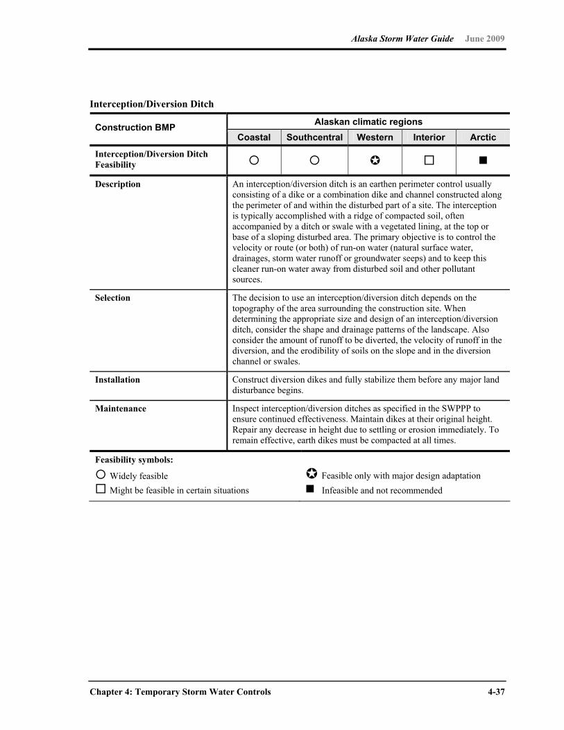
Alaska Storm Water Guide June 2009
Chapter 4: Temporary Storm Water Controls 4-37
Interception/Diversion Ditch
Alaskan climatic regions Construction BMP Coastal Southcentral Western Interior Arctic
Interception/Diversion Ditch Feasibility
Description An interception/diversion ditch is an earthen perimeter control usually consisting of a dike or a combination dike and channel constructed along the perimeter of and within the disturbed part of a site. The interception is typically accomplished with a ridge of compacted soil, often accompanied by a ditch or swale with a vegetated lining, at the top or base of a sloping disturbed area. The primary objective is to control the velocity or route (or both) of run-on water (natural surface water, drainages, storm water runoff or groundwater seeps) and to keep this cleaner run-on water away from disturbed soil and other pollutant sources.
Selection The decision to use an interception/diversion ditch depends on the topography of the area surrounding the construction site. When determining the appropriate size and design of an interception/diversion ditch, consider the shape and drainage patterns of the landscape. Also consider the amount of runoff to be diverted, the velocity of runoff in the diversion, and the erodibility of soils on the slope and in the diversion channel or swales.
Installation Construct diversion dikes and fully stabilize them before any major land disturbance begins.
Maintenance Inspect interception/diversion ditches as specified in the SWPPP to ensure continued effectiveness. Maintain dikes at their original height. Repair any decrease in height due to settling or erosion immediately. To remain effective, earth dikes must be compacted at all times.
Feasibility symbols:
Widely feasible Might be feasible in certain situations
Feasible only with major design adaptation Infeasible and not recommended
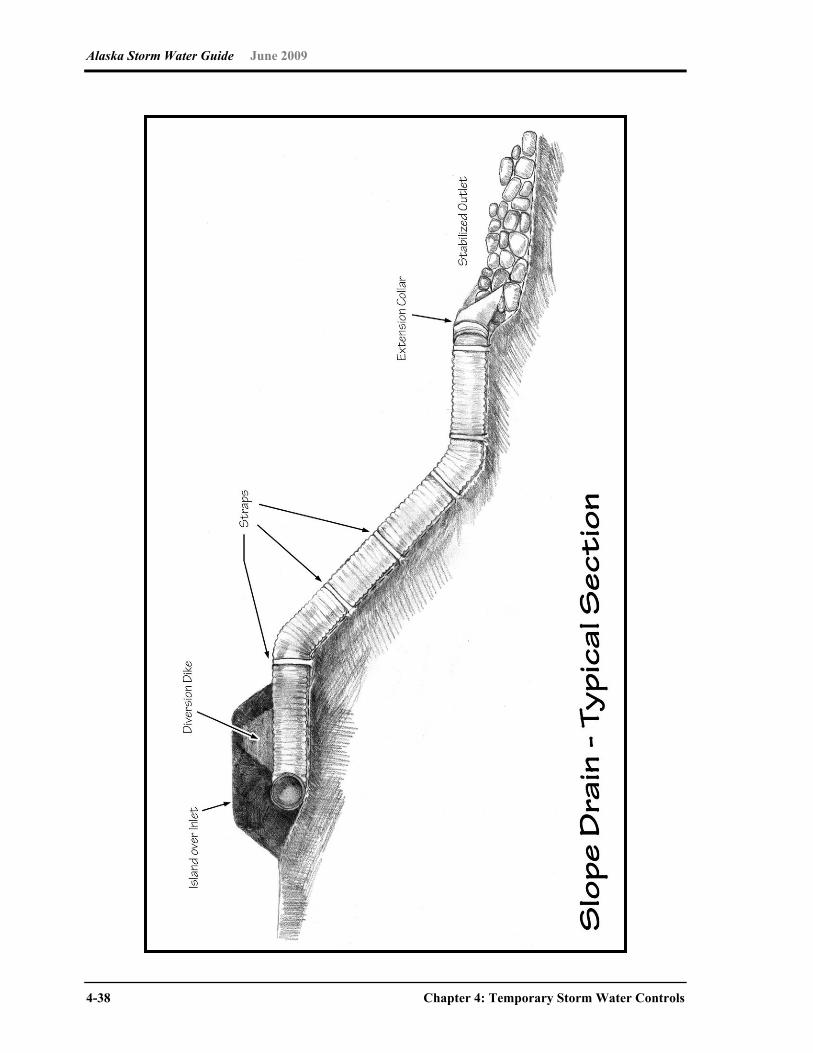
Alaska Storm Water Guide June 2009
4-38 Chapter 4: Temporary Storm Water Controls
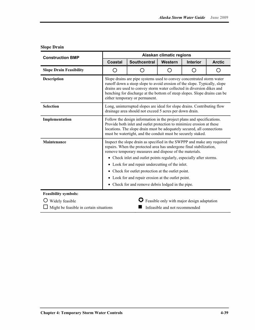
Alaska Storm Water Guide June 2009
Chapter 4: Temporary Storm Water Controls 4-39
Slope Drain
Alaskan climatic regions Construction BMP Coastal Southcentral Western Interior Arctic
Slope Drain Feasibility Description Slope drains are pipe systems used to convey concentrated storm water
runoff down a steep slope to avoid erosion of the slope. Typically, slope drains are used to convey storm water collected in diversion dikes and benching for discharge at the bottom of steep slopes. Slope drains can be either temporary or permanent.
Selection Long, uninterrupted slopes are ideal for slope drains. Contributing flow drainage area should not exceed 5 acres per down drain.
Implementation Follow the design information in the project plans and specifications. Provide both inlet and outlet protection to minimize erosion at these locations. The slope drain must be adequately secured, all connections must be watertight, and the conduit must be securely staked.
Maintenance Inspect the slope drain as specified in the SWPPP and make any required repairs. When the protected area has undergone final stabilization, remove temporary measures and dispose of the materials. Check inlet and outlet points regularly, especially after storms. Look for and repair undercutting of the inlet. Check for outlet protection at the outlet point. Look for and repair erosion at the outlet point. Check for and remove debris lodged in the pipe.
Feasibility symbols:
Widely feasible Might be feasible in certain situations
Feasible only with major design adaptation Infeasible and not recommended
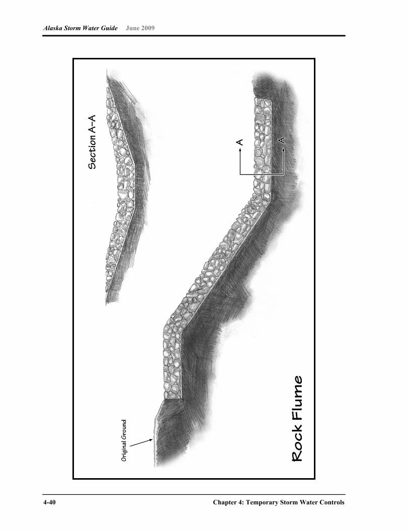
Alaska Storm Water Guide June 2009
4-40 Chapter 4: Temporary Storm Water Controls
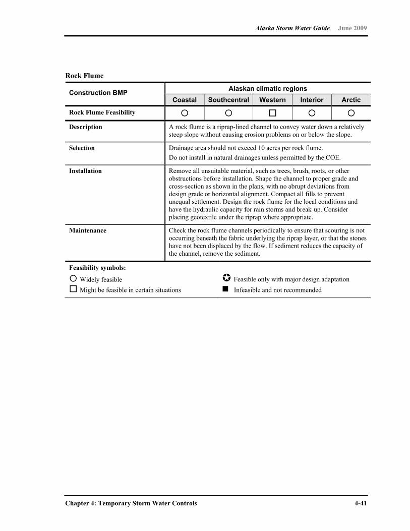
Alaska Storm Water Guide June 2009
Chapter 4: Temporary Storm Water Controls 4-41
Rock Flume
Alaskan climatic regions Construction BMP Coastal Southcentral Western Interior Arctic
Rock Flume Feasibility Description A rock flume is a riprap-lined channel to convey water down a relatively
steep slope without causing erosion problems on or below the slope.
Selection Drainage area should not exceed 10 acres per rock flume. Do not install in natural drainages unless permitted by the COE.
Installation Remove all unsuitable material, such as trees, brush, roots, or other obstructions before installation. Shape the channel to proper grade and cross-section as shown in the plans, with no abrupt deviations from design grade or horizontal alignment. Compact all fills to prevent unequal settlement. Design the rock flume for the local conditions and have the hydraulic capacity for rain storms and break-up. Consider placing geotextile under the riprap where appropriate.
Maintenance Check the rock flume channels periodically to ensure that scouring is not occurring beneath the fabric underlying the riprap layer, or that the stones have not been displaced by the flow. If sediment reduces the capacity of the channel, remove the sediment.
Feasibility symbols:
Widely feasible Might be feasible in certain situations
Feasible only with major design adaptation Infeasible and not recommended
Alaska Storm Water Guide June 2009
4-42 Chapter 4: Temporary Storm Water Controls
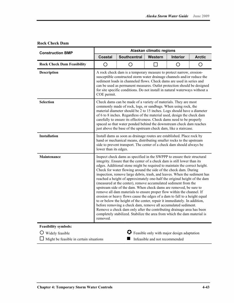
Alaska Storm Water Guide June 2009
Chapter 4: Temporary Storm Water Controls 4-43
Rock Check Dam
Alaskan climatic regions Construction BMP Coastal Southcentral Western Interior Arctic
Rock Check Dam Feasibility Description A rock check dam is a temporary measure to protect narrow, erosion-
susceptible constructed storm water drainage channels and/or reduce the sediment loads in channeled flows. Check dams are used in series and can be used as permanent measures. Outlet protection should be designed for site specific conditions. Do not install in natural waterways without a COE permit.
Selection Check dams can be made of a variety of materials. They are most commonly made of rock, logs, or sandbags. When using rock, the material diameter should be 2 to 15 inches. Logs should have a diameter of 6 to 8 inches. Regardless of the material used, design the check dam carefully to ensure its effectiveness. Check dams need to be properly spaced so that water ponded behind the downstream check dam reaches just above the base of the upstream check dam, like a staircase.
Installation Install dams as soon as drainage routes are established. Place rock by hand or mechanical means, distributing smaller rocks to the upstream side to prevent transport. The center of a check dam should always be lower than its edges.
Maintenance Inspect check dams as specified in the SWPPP to ensure their structural integrity. Ensure that the center of a check dam is still lower than its edges. Additional stone might be required to maintain the correct height. Check for water flowing around the side of the check dam. During inspection, remove large debris, trash, and leaves. When the sediment has reached a height of approximately one-half the original height of the dam (measured at the center), remove accumulated sediment from the upstream side of the dam. When check dams are removed, be sure to remove all dam materials to ensure proper flow within the channel. If erosion or heavy flows cause the edges of a dam to fall to a height equal to or below the height of the center, repair it immediately. In addition, before removing a check dam, remove all accumulated sediment. Remove a check dam only after the contributing drainage area has been completely stabilized. Stabilize the area from which the dam material is removed.
Feasibility symbols:
Widely feasible Might be feasible in certain situations
Feasible only with major design adaptation Infeasible and not recommended

Alaska Storm Water Guide June 2009
4-44 Chapter 4: Temporary Storm Water Controls

Alaska Storm Water Guide June 2009
Chapter 4: Temporary Storm Water Controls 4-45
Outlet Protection
Alaskan climatic regions Construction BMP Coastal Southcentral Western Interior Arctic
Outlet Protection Feasibility Description An outlet protection is a structure designed for site-specific conditions to
control erosion at the outlet of a pipe by armoring surrounding soils, reducing flow velocity and dissipating flow energy.
Selection Outlet protection should be used whenever the energy from runoff being discharged from a BMP or exiting a construction site needs to be dissipated.
Installation The riprap apron should be extended downstream until stable conditions are reached even though this might exceed the length calculated for design velocity control. If the pipe discharges into a well-defined channel, the side slopes of the channel should not be steeper than 2:1 (horizontal:vertical)
Maintenance Inspect outlet protection according to the schedule in the SWPPP to identify necessary repairs, such as scouring, sediment accumulation, or damage to the outfall. Make immediate repairs if any conditions noted under inspection are found. Sediment should be removed when it fills the voids between rocks.
Feasibility symbols:
Widely feasible Might be feasible in certain situations
Feasible only with major design adaptation Infeasible and not recommended
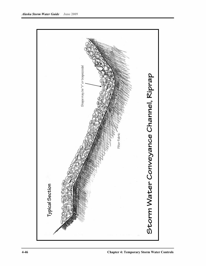
Alaska Storm Water Guide June 2009
4-46 Chapter 4: Temporary Storm Water Controls

Alaska Storm Water Guide June 2009
Chapter 4: Temporary Storm Water Controls 4-47
Storm Water Conveyance Channel
Alaskan climatic regions Construction BMP Coastal Southcentral Western Interior Arctic
Storm Water Conveyance Channel Feasibility
Description A storm water conveyance is a channel lined with vegetation, riprap, or other flexible material designed for the conveyance and safe disposal of concentrated surface runoff to a receiving system without damage from erosion.
Selection Channels should be located to conform with and use the natural gradient.
Grass-lined channels should not be subject to sedimentation from disturbed areas.
Grass-lined channels might be unsuitable if channel slopes over 5% predominate, continuous or prolonged flows occur, potential exists for damage from traffic (people or vehicles) or soils are erodible.
Channel side slopes should be 2:1 or flatter in the case of rock-riprap lining. Vegetated channel side slopes should be 4:1 or flatter.
Installation Remove all unsuitable material, such as trees, brush, roots, or other obstructions before installation. Shape the channel to proper grade and cross-section as shown in the plans, with no abrupt deviations from design grade or horizontal alignment. Compact all fills to prevent unequal settlement. Remove any excess soil and dispose of properly.
Maintenance Inspect and repair grass, riprap, or mat liner as necessary.
Feasibility symbols:
Widely feasible Might be feasible in certain situations
Feasible only with major design adaptation Infeasible and not recommended

Alaska Storm Water Guide June 2009
4-48 Chapter 4: Temporary Storm Water Controls
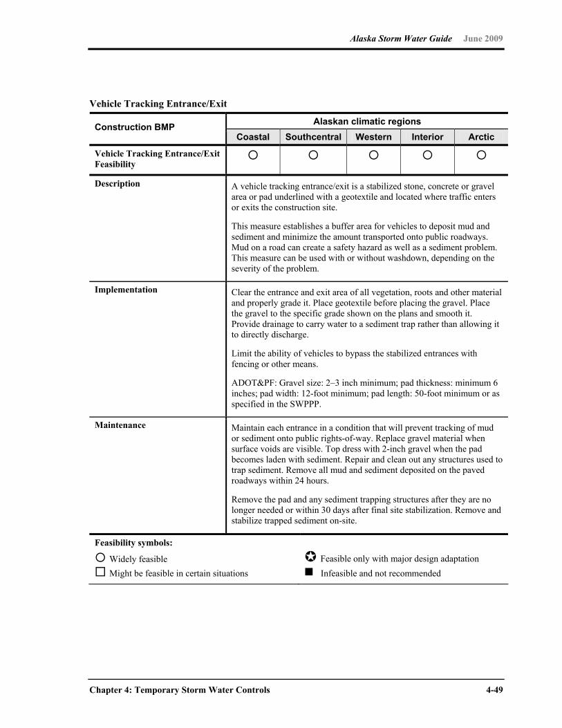
Alaska Storm Water Guide June 2009
Chapter 4: Temporary Storm Water Controls 4-49
Vehicle Tracking Entrance/Exit
Alaskan climatic regions Construction BMP Coastal Southcentral Western Interior Arctic
Vehicle Tracking Entrance/Exit Feasibility
Description A vehicle tracking entrance/exit is a stabilized stone, concrete or gravel area or pad underlined with a geotextile and located where traffic enters or exits the construction site.
This measure establishes a buffer area for vehicles to deposit mud and sediment and minimize the amount transported onto public roadways. Mud on a road can create a safety hazard as well as a sediment problem. This measure can be used with or without washdown, depending on the severity of the problem.
Implementation Clear the entrance and exit area of all vegetation, roots and other material and properly grade it. Place geotextile before placing the gravel. Place the gravel to the specific grade shown on the plans and smooth it. Provide drainage to carry water to a sediment trap rather than allowing it to directly discharge.
Limit the ability of vehicles to bypass the stabilized entrances with fencing or other means.
ADOT&PF: Gravel size: 2–3 inch minimum; pad thickness: minimum 6 inches; pad width: 12-foot minimum; pad length: 50-foot minimum or as specified in the SWPPP.
Maintenance Maintain each entrance in a condition that will prevent tracking of mud or sediment onto public rights-of-way. Replace gravel material when surface voids are visible. Top dress with 2-inch gravel when the pad becomes laden with sediment. Repair and clean out any structures used to trap sediment. Remove all mud and sediment deposited on the paved roadways within 24 hours.
Remove the pad and any sediment trapping structures after they are no longer needed or within 30 days after final site stabilization. Remove and stabilize trapped sediment on-site.
Feasibility symbols:
Widely feasible Might be feasible in certain situations
Feasible only with major design adaptation Infeasible and not recommended
Alaska Storm Water Guide June 2009
4-50 Chapter 4: Temporary Storm Water Controls
4.4 Good Housekeeping BMPs
Construction projects generate large amounts of building-related waste, which can end up
polluting storm water runoff if not properly managed. The suite of BMPs that are described
in the SWPPP must include pollution prevention (P2) or good housekeeping practices that
are designed to prevent contamination of storm water from a wide range of materials and
wastes at the construction site. The six principles described below (USEPA 2007) are
designed to help identify the P2 practices that should be described in SWPPPs and
implemented at construction sites. The principles are followed by descriptions of several
common good housekeeping BMPs.
A construction SWPPP is more than just an ESC plan! The SWPPP must address
pollutants other than sediment that are often found at construction sites such as concrete
waste, paint, trash and debris, fuel and oil.
P2 Principle 1: Provide for waste management. Design proper management procedures
and practices to prevent the discharge of pollutants to storm water from solid or liquid
wastes that will be generated at the construction site. Practices such as establishing
dedicated trash disposal areas, recycling, proper material handling and cleanup measures
can reduce the potential for storm water runoff to pick up construction site wastes and
discharge them to surface waters.
Provide convenient, well-maintained, and properly located toilet facilities. Provide for regular
inspections, service, and disposal. Locate toilet facilities away from storm drain inlets and
waterways to prevent accidental spills and contamination of storm water. Ensure that toilet
facilities are situated so they will not be overturned by vehicle collisions or other accidents.
Treat or dispose of sanitary and septic waste in accordance with state or local regulations.
Proper material use, storage, waste disposal, and training of employees and subcontractors
can prevent or reduce the discharge of hazardous and toxic wastes to storm water.
Implement a comprehensive set of waste-management practices for hazardous or toxic
materials, such as paints, solvents, petroleum products, pesticides, wood preservatives,
acids, roofing tar and other materials. Practices should include storage, handling, inventory
and cleanup procedures for spills (see the following P2 principles).
P2 Principle 2: Establish proper building material handling and staging areas. The
SWPPP should include comprehensive handling and management procedures for building
materials, especially those that are hazardous or toxic. Paints, solvents, pesticides, fuels
Alaska Storm Water Guide June 2009
Chapter 4: Temporary Storm Water Controls 4-51
and oils, other hazardous materials or any building materials that have the potential to
contaminate storm water should be stored indoors or under cover whenever possible or in
areas with secondary containment. Secondary containment prevents a spill from spreading
across the site and includes dikes, berms, curbing or other containment methods.
Secondary containment techniques should also ensure the protection of groundwater.
Designate staging areas for activities such as fueling vehicles, mixing paints, plaster, mortar
and so on. Designated staging areas will help to monitor the use of materials and to clean
up any spills. Training employees and subcontractors is essential to the success of this P2
principle.
P2 Principle 3: Designate and ensure use of washout areas. Where possible, concrete
contractors should be encouraged to use the washout facilities at their own plants or
dispatch facilities. If it is necessary to provide for concrete washout areas on-site, designate
specific washout areas and design facilities to handle anticipated washout water. Washout
areas should also be provided for paint and stucco operations. Because washout areas can
be a source of pollutants from leaks or spills, locate them at least 50 feet away from storm
drains and watercourses whenever possible. In no instance should washout water be
allowed to discharge to a storm drain or surface water.
Regularly inspect and maintain washouts, which can fill up quickly when concrete, paint, and
stucco work are occurring on large portions of the site. Inspect for evidence that contractors
are using the washout areas and not dumping materials onto the ground or into drainage
facilities. If the washout areas are not being used regularly, consider posting additional
signage, relocating the facilities to more convenient locations or providing training to workers
and contractors.
P2 Principle 4: Establish proper equipment/vehicle fueling and maintenance practices. Performing equipment/vehicle fueling and maintenance at an off-site facility is
preferred over performing such activities on the site, particularly for road vehicles
(e.g., trucks, vans). For grading and excavating equipment, this is usually not possible or
desirable. Create an on-site fueling and maintenance area that is clean and dry. The on-site
fueling area should have a spill kit, and staff should know how to use it. If possible, conduct
vehicle fueling and maintenance activities in a covered area; outdoor vehicle fueling and
maintenance is a potentially significant source of storm water pollution. Significant
maintenance on vehicles and equipment should be conducted at a properly controlled, off-
site facility.
P2 Principle 5: Control equipment/vehicle washing and allowable non-storm water discharges. Environmentally friendly washing practices can be practiced at every
construction site to prevent contamination of surface and groundwater from wash water.

Alaska Storm Water Guide June 2009
4-52 Chapter 4: Temporary Storm Water Controls
Procedures and practices include using off-site facilities; washing in designated, contained
areas only; eliminating discharges to the storm drain by infiltrating the wash water or routing
to the sanitary sewer; and training employees and subcontractors in proper cleaning
procedures.
Allowable non-storm water discharges include the following:
Discharges from fire-fighting activities
Fire hydrant flushings
Waters used to wash vehicles where detergents are not used
Water used to control dust in accordance with Subpart 3.4.G of the CGP
Potable water including uncontaminated water line flushings
Routine external building wash down that does not use detergents
Pavement wash waters where spills or leaks of toxic or hazardous materials have not occurred (unless all spilled material has been removed) and where detergents are not used
Uncontaminated air conditioning or compressor condensate
Uncontaminated groundwater or spring water
Foundation or footing drains where flows are not contaminated with process materials such as solvents
Uncontaminated excavation dewatering
Landscape irrigation
P2 Principle 6: Develop and implement a spill prevention and response plan. Develop
a spill prevention and response plan that will be included or incorporated into the SWPPP.
The plan should clearly identify ways to reduce the chance of spills, stop the source of spills,
contain and clean up spills, dispose of materials contaminated by spills, and train personnel
responsible for spill prevention and response. The plan should also specify material
handling procedures and storage requirements and ensure that clear and concise spill
cleanup procedures are provided and posted for areas in which spills could occur. When
developing a spill prevention and response plan, include, at a minimum, the following:
Note the locations of chemical storage areas, storm drains, tributary drainage areas, surface waterbodies on or near the site, and measures to stop spills from leaving the site

Alaska Storm Water Guide June 2009
Chapter 4: Temporary Storm Water Controls 4-53
Specify how to notify appropriate authorities, such as police and fire departments, hospitals or municipal sewage treatment facilities to request assistance
Describe the procedures for immediate cleanup of spills and proper disposal
Identify personnel responsible for implementing the plan if there is a spill
Specify procedures to immediately document and clean up spills
The following information in Table 4-2 on common good housekeeping BMPs is summarized
from EPA’s Menu of BMPs (see Link 62 in Appendix A).
Table 4-2. Feasibility of good housekeeping BMPs, based on Alaskan climatic regions
Alaskan climatic regions Good housekeeping BMPs Coastal Southcentral Western Interior Arctic
Concrete Washout General Construction Site Waste Management
Spill Prevention and Control Plan Vehicle Maintenance and Washing Feasibility symbols:
Widely feasible Might be feasible in certain situations
Feasible only with major design adaptation Infeasible and not recommended
Note: These recommendations are general guidance; site-specific conditions will dictate proper BMP selection
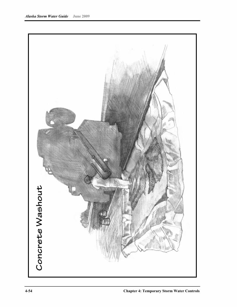
Alaska Storm Water Guide June 2009
4-54 Chapter 4: Temporary Storm Water Controls
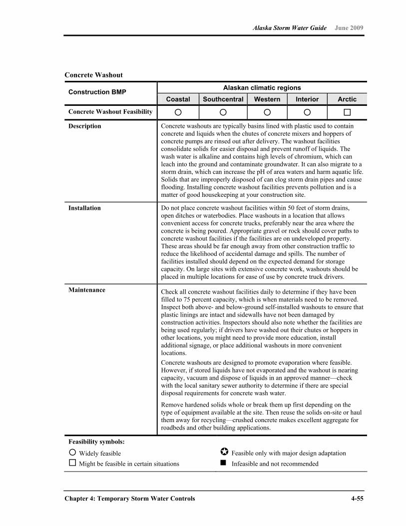
Alaska Storm Water Guide June 2009
Chapter 4: Temporary Storm Water Controls 4-55
Concrete Washout
Alaskan climatic regions Construction BMP Coastal Southcentral Western Interior Arctic
Concrete Washout Feasibility Description Concrete washouts are typically basins lined with plastic used to contain
concrete and liquids when the chutes of concrete mixers and hoppers of concrete pumps are rinsed out after delivery. The washout facilities consolidate solids for easier disposal and prevent runoff of liquids. The wash water is alkaline and contains high levels of chromium, which can leach into the ground and contaminate groundwater. It can also migrate to a storm drain, which can increase the pH of area waters and harm aquatic life. Solids that are improperly disposed of can clog storm drain pipes and cause flooding. Installing concrete washout facilities prevents pollution and is a matter of good housekeeping at your construction site.
Installation Do not place concrete washout facilities within 50 feet of storm drains, open ditches or waterbodies. Place washouts in a location that allows convenient access for concrete trucks, preferably near the area where the concrete is being poured. Appropriate gravel or rock should cover paths to concrete washout facilities if the facilities are on undeveloped property. These areas should be far enough away from other construction traffic to reduce the likelihood of accidental damage and spills. The number of facilities installed should depend on the expected demand for storage capacity. On large sites with extensive concrete work, washouts should be placed in multiple locations for ease of use by concrete truck drivers.
Maintenance Check all concrete washout facilities daily to determine if they have been filled to 75 percent capacity, which is when materials need to be removed. Inspect both above- and below-ground self-installed washouts to ensure that plastic linings are intact and sidewalls have not been damaged by construction activities. Inspectors should also note whether the facilities are being used regularly; if drivers have washed out their chutes or hoppers in other locations, you might need to provide more education, install additional signage, or place additional washouts in more convenient locations. Concrete washouts are designed to promote evaporation where feasible. However, if stored liquids have not evaporated and the washout is nearing capacity, vacuum and dispose of liquids in an approved manner—check with the local sanitary sewer authority to determine if there are special disposal requirements for concrete wash water.
Remove hardened solids whole or break them up first depending on the type of equipment available at the site. Then reuse the solids on-site or haul them away for recycling—crushed concrete makes excellent aggregate for roadbeds and other building applications.
Feasibility symbols:
Widely feasible Might be feasible in certain situations
Feasible only with major design adaptation Infeasible and not recommended

Alaska Storm Water Guide June 2009
4-56 Chapter 4: Temporary Storm Water Controls

Alaska Storm Water Guide June 2009
Chapter 4: Temporary Storm Water Controls 4-57
General Construction Site Waste Management
Alaskan climatic regions Construction BMP Coastal Southcentral Western Interior Arctic
General Construction Site Waste Management Feasibility
Description Building materials and other construction site wastes must be properly managed and disposed of to reduce the risk of pollution from materials such as surplus or refuse building materials or hazardous wastes. Practices such as trash disposal, recycling, proper material handling, and spill prevention and cleanup measures can reduce the potential for storm water runoff to mobilize construction site wastes and contaminate surface or groundwater.
Installation Solid Wastes: Designate a waste collection area on the site that does not receive a
substantial amount of runoff from upland areas and does not drain directly to a waterbody.
Ensure that containers have lids so they can be covered before periods of rain, and keep containers in a covered area whenever possible.
If secondary containment is used, include a protocol in the SWPPP and train employees on disposal of accumulated precipitation.
Schedule waste collection to prevent the containers from overfilling. Clean up spills immediately. For hazardous materials, follow
cleanup instructions on the package. Use an absorbent material such as sawdust or kitty litter to contain the spill.
During the demolition phase of construction, provide extra containers and schedule more frequent pickups.
Collect, remove and dispose of all construction site wastes at authorized disposal areas. Contact a local environmental agency to identify these disposal sites.
Hazardous Materials and Wastes: Consult with local waste management authorities about the
requirements for disposing of hazardous materials. To prevent leaks, empty and clean hazardous waste containers before
disposing of them. Never remove the original product label from the container because
it contains important safety information. Follow the manufacturer’s recommended method of disposal, which should be printed on the label.
Never mix excess products when disposing of them, unless specifically recommended by the manufacturer.

Alaska Storm Water Guide June 2009
4-58 Chapter 4: Temporary Storm Water Controls
General Construction Site Waste Management (continued)
Installation (continued)
Pesticides and fertilizers: Follow all federal, state and local regulations that apply to the use,
handling or disposal of pesticides and fertilizers. Store pesticides and fertilizers in a dry, covered area. Construct berms or dikes to contain stored pesticides and fertilizers
in case of spillage. Follow the recommended application rates and methods. Have equipment and absorbent materials available in storage and
application areas to contain and clean up any spills that occur. Petroleum Products: Store new and used petroleum products in covered areas, where
practicable, and place within berms or dikes to contain any spills. Immediately contain and clean up any spills with absorbent
materials. Have equipment available in fuel storage areas and in vehicles to
contain and clean up any spills that occur. Detergents: Use detergents only as recommended, and limit their use on the site.
Do not dump wash water containing detergents into the storm drain system; direct it to a sanitary sewer or contain it so that it can be treated at a wastewater treatment plant.
Maintenance Inspect storage and use areas and identify containers or equipment that could malfunction and cause leaks or spills. Check equipment and containers for leaks, corrosion, support or foundation failure, or other signs of deterioration, and test them for soundness. Immediately repair or replace any that are found to be defective.
Feasibility symbols:
Widely feasible Might be feasible in certain situations
Feasible only with major design adaptation Infeasible and not recommended

Alaska Storm Water Guide June 2009
Chapter 4: Temporary Storm Water Controls 4-59
This page intentionally left blank.

Alaska Storm Water Guide June 2009
4-60 Chapter 4: Temporary Storm Water Controls
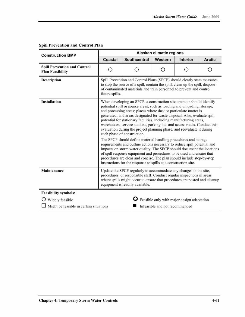
Alaska Storm Water Guide June 2009
Chapter 4: Temporary Storm Water Controls 4-61
Spill Prevention and Control Plan
Alaskan climatic regions Construction BMP Coastal Southcentral Western Interior Arctic
Spill Prevention and Control Plan Feasibility
Description Spill Prevention and Control Plans (SPCP) should clearly state measures to stop the source of a spill, contain the spill, clean up the spill, dispose of contaminated materials and train personnel to prevent and control future spills.
Installation When developing an SPCP, a construction site operator should identify potential spill or source areas, such as loading and unloading, storage, and processing areas; places where dust or particulate matter is generated; and areas designated for waste disposal. Also, evaluate spill potential for stationary facilities, including manufacturing areas, warehouses, service stations, parking lots and access roads. Conduct this evaluation during the project planning phase, and reevaluate it during each phase of construction. The SPCP should define material handling procedures and storage requirements and outline actions necessary to reduce spill potential and impacts on storm water quality. The SPCP should document the locations of spill response equipment and procedures to be used and ensure that procedures are clear and concise. The plan should include step-by-step instructions for the response to spills at a construction site.
Maintenance Update the SPCP regularly to accommodate any changes in the site, procedures, or responsible staff. Conduct regular inspections in areas where spills might occur to ensure that procedures are posted and cleanup equipment is readily available.
Feasibility symbols:
Widely feasible Might be feasible in certain situations
Feasible only with major design adaptation Infeasible and not recommended
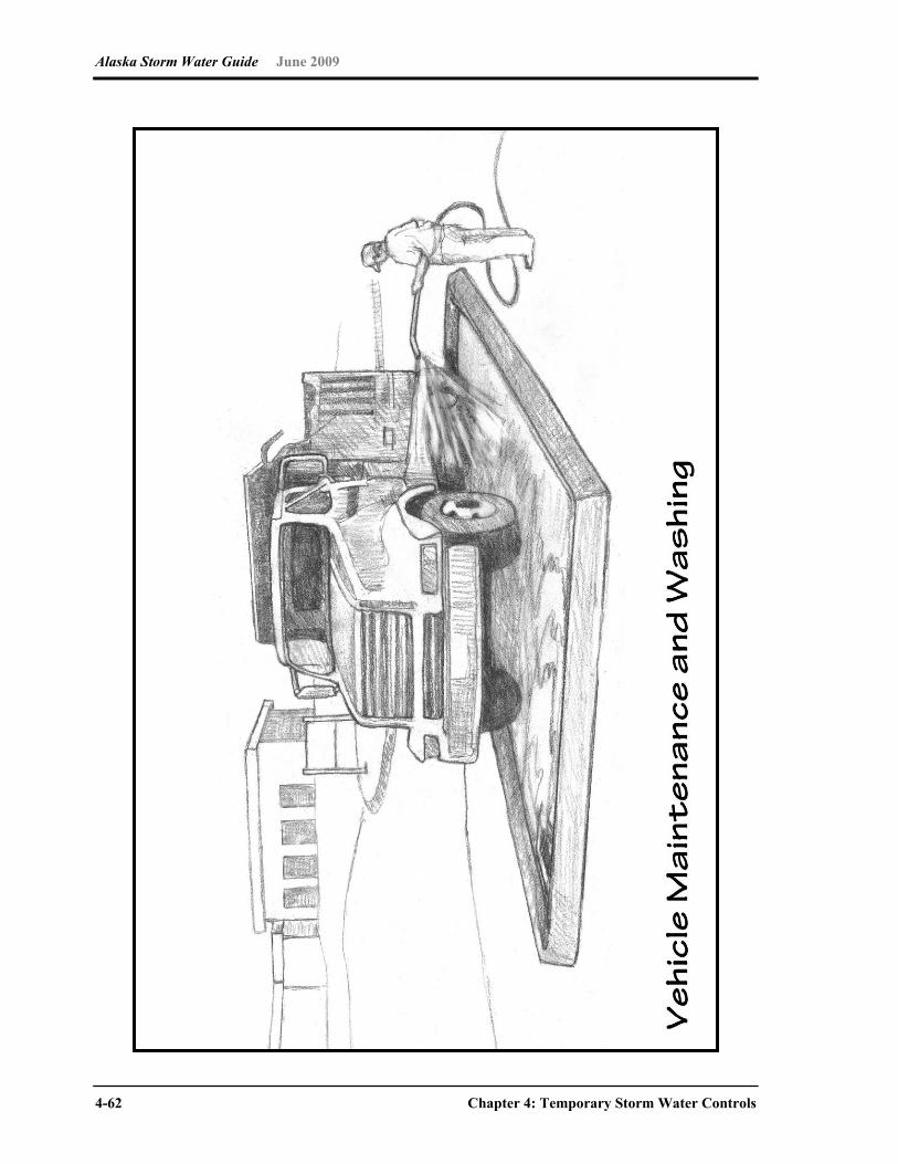
Alaska Storm Water Guide June 2009
4-62 Chapter 4: Temporary Storm Water Controls
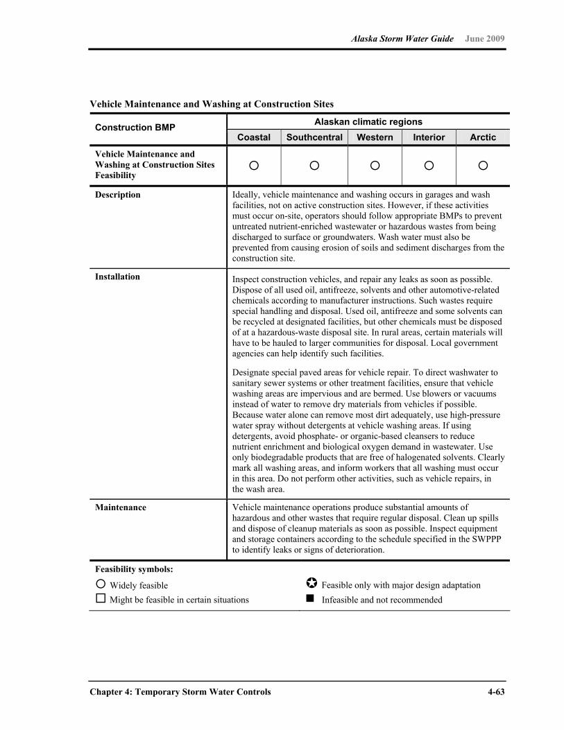
Alaska Storm Water Guide June 2009
Chapter 4: Temporary Storm Water Controls 4-63
Vehicle Maintenance and Washing at Construction Sites
Alaskan climatic regions Construction BMP Coastal Southcentral Western Interior Arctic
Vehicle Maintenance and Washing at Construction Sites Feasibility
Description Ideally, vehicle maintenance and washing occurs in garages and wash facilities, not on active construction sites. However, if these activities must occur on-site, operators should follow appropriate BMPs to prevent untreated nutrient-enriched wastewater or hazardous wastes from being discharged to surface or groundwaters. Wash water must also be prevented from causing erosion of soils and sediment discharges from the construction site.
Installation Inspect construction vehicles, and repair any leaks as soon as possible. Dispose of all used oil, antifreeze, solvents and other automotive-related chemicals according to manufacturer instructions. Such wastes require special handling and disposal. Used oil, antifreeze and some solvents can be recycled at designated facilities, but other chemicals must be disposed of at a hazardous-waste disposal site. In rural areas, certain materials will have to be hauled to larger communities for disposal. Local government agencies can help identify such facilities.
Designate special paved areas for vehicle repair. To direct washwater to sanitary sewer systems or other treatment facilities, ensure that vehicle washing areas are impervious and are bermed. Use blowers or vacuums instead of water to remove dry materials from vehicles if possible. Because water alone can remove most dirt adequately, use high-pressure water spray without detergents at vehicle washing areas. If using detergents, avoid phosphate- or organic-based cleansers to reduce nutrient enrichment and biological oxygen demand in wastewater. Use only biodegradable products that are free of halogenated solvents. Clearly mark all washing areas, and inform workers that all washing must occur in this area. Do not perform other activities, such as vehicle repairs, in the wash area.
Maintenance Vehicle maintenance operations produce substantial amounts of hazardous and other wastes that require regular disposal. Clean up spills and dispose of cleanup materials as soon as possible. Inspect equipment and storage containers according to the schedule specified in the SWPPP to identify leaks or signs of deterioration.
Feasibility symbols:
Widely feasible Might be feasible in certain situations
Feasible only with major design adaptation Infeasible and not recommended
Alaska Storm Water Guide June 2009
4-64 Chapter 4: Temporary Storm Water Controls
4.5 Inspections, Maintenance and Recordkeeping
Construction Site Inspections BMPs must be maintained in good working order at all times. To ensure that BMPs are
maintained, conduct regular inspections and document the findings of the inspections in the
SWPPP.
Inspections must be conducted either at least once every 7 calendar days, or at least once
every 14 calendar days and within 24 hours of the end of a storm event of 0.5 inch or
greater. However, some construction sites will need to be inspected more frequently.
In developing an inspection schedule consider the following:
Consider using spot inspections. Inspect certain parts of the site more frequently or even daily. Target places that need extra attention, such as areas around construction site entrances, check nearby streets for dirt, check inlet protection, and so on.
Consider adding inspections before and during rain events. Consult the most recent CGP for inspection frequencies. For example, the current EPA CGP requires an inspection after rain events of 0.5 inch or greater in one of the two inspection frequency options. Consider adding inspections before or during predicted rain events, and conduct inspections after rain events of less than 0.5 inch and during significant snowmelt. Consult a local weather source and initiate inspections before predicted storm events as a way to ensure that controls are operational.
Train staff and subcontractors. Use staff and subcontractors to help identify any potential problems with BMPs. Again, document any issues that are confirmed problems.
Inspection Reports Complete an inspection report after each inspection. Retain copies of all inspection reports
and keep them with or in the SWPPP. Generally, the following information is required to be
included in an inspection report:
Inspection date.
Inspector information, including the names, titles and qualifications of personnel conducting the inspection.
Alaska Storm Water Guide June 2009
Chapter 4: Temporary Storm Water Controls 4-65
Weather information for the period since the last inspection (or for the first inspection since beginning construction activity) including a best estimate of the beginning of each storm, its duration, approximate amount of rainfall for each storm (in inches) and whether any discharges occurred. Create a log to record the basic weather information or keep copies of weather information from a reliable local source, such as the Internet sites of local newspapers, TV stations, local universities, and so on.
Current weather information and a description of any discharges occurring at the time of the inspection.
Descriptions of evidence of previous or ongoing discharges of sediment or other pollutants from the site.
Location(s) of BMPs that need to be maintained.
Location(s) of BMPs that failed to operate as designed or proved inadequate for a location.
Location(s) where additional BMPs are needed but did not exist at the time of inspection.
Corrective action required, including any necessary changes to the SWPPP and implementation dates.
A certification that the site is in compliance with the most recent CGP or identification of noncompliance issues, signed by the appropriate responsible official.
The Appendix G, Part 11.D certification statement (of the most recent CGP), along with the signature of an authorizing official or duly authorized representative.
Consider taking digital photographs during inspections to document BMPs, problems
identified and progress in implementing the SWPPP.
Maintaining BMPs Implementing a good BMP maintenance program is essential to an SWPPP’s success and
to efforts to protect nearby waterways. Maintain BMPs regularly and whenever an inspection
(formal or informal) identifies a problem or potential issue. For instance, trash and debris
should be cleaned up, dumpsters should be checked and covered, nearby streets and
sidewalks should be swept daily, and so on. Maintenance on ESCs should be performed
before the next storm event or as soon as site conditions allow. Consider the following
points when conducting maintenance:
Follow the designers or manufacturer’s recommended maintenance procedures for all BMPs

Alaska Storm Water Guide June 2009
4-66 Chapter 4: Temporary Storm Water Controls
BMP maintenance will vary according to the specific area and site conditions
Remove sediment from BMPs as appropriate and always before any sediment control reaches 50 percent of design capacity, and properly dispose of sediment into controlled areas to prevent soil from returning to the BMP during subsequent rain events
Remove sediment from paved roadways and from around BMPs protecting storm drain inlets
Ensure that construction support activities, including borrow areas, waste areas, contractor work areas, material storage areas, and dedicated concrete and asphalt batch plants are cleaned and maintained
Replace damaged BMPs, such as silt fences, that no longer operate effectively
Implement new BMPs where previous controls are found to be ineffective, and update the SWPPP accordingly within 7 days
Keep a record of all maintenance activities, including the date, BMP, location, and maintenance performed in the SWPPP
Recordkeeping Keep copies of the SWPPP, inspection records, copies of all reports required by the permit,
and records of all data used to complete the NOI to be covered by the permit for a period of
at least 3 years from the date that permit coverage expires or is terminated.
Records should include the following:
A copy of the SWPPP, with any modifications
A copy of the NOI and NOT and any storm water-related correspondence with federal, state and local regulatory authorities
Inspection forms, including the date, place and time of BMP inspections
Names of inspector(s)
The date, time, exact location and a characterization of significant observations, including spills and leaks
Records of any non-storm water discharges
BMP corrective actions taken at the site (Corrective Action Log)
Alaska Storm Water Guide June 2009
Chapter 4: Temporary Storm Water Controls 4-67
Any documentation and correspondence related to endangered species and historic preservation requirements
Weather conditions (e.g., temperature, precipitation)
Date(s) when major land-disturbance activities (e.g. clearing, grading and excavating) occur in any portion of the site
Date(s) when construction activities are either temporarily or permanently ceased in a portion of the site
Date(s) when either temporary or permanent stabilization is initiated in an area
4.6 Common Problems with SWPPPs and Temporary BMPs
As the saying goes, “you learn from your mistakes.” To help you avoid making the same
mistakes, this final section under temporary storm water controls describes some of the
most common problems found at construction sites (adapted from MPCA 2004):
Problem #1—Not using phased grading or providing temporary or permanent cover (i.e., soil stabilization)
In general, construction site operators should phase the grading activities so that only
a portion of the site is exposed at any time. Also, disturbed areas that are not being
actively worked should have temporary cover. Areas that are at final grade should
receive permanent cover as soon as possible.
Problem #2—No sediment controls on-site Sediment controls, including inlet protection, such as silt fences, sediment barriers,
sediment traps and basins must be in place before soil-disturbance activities begin.
Ensure that BMPs are always installed and maintained when in proximity to a stream
or sensitive area. Do not proceed with grading work out-of-phase.
Problem #3—No erosion control for temporary stockpiles Temporary stockpiles must be seeded, or otherwise covered, and surrounded by
properly installed silt fence. Stockpiles should not be placed on paved surfaces.
Problem #4—Improper storm drain inlet protection Storm drain lnlets that receive storm water discharges from an active construction site
should be protected with a temporary filtering measure to trap sediment and prevent
sediment from entering the storm drain system.
Alaska Storm Water Guide June 2009
4-68 Chapter 4: Temporary Storm Water Controls
Problem #5—No BMPs to minimize vehicle tracking onto the road Vehicle exits must use BMPs such as stone pads, concrete or steel wash racks, or
equivalent systems to prevent vehicle tracking of sediment.
Problem #6—Improper solid waste or hazardous waste management Solid waste (including trash and debris) must be disposed of properly, and hazardous
materials (including oil, gasoline and paint) must be properly stored (which includes
secondary containment). Properly manage portable sanitary facilities.
Problem #7—Dewatering and other pollutant discharges at the construction site Construction site dewatering of contaminated water from building footings or other
sources should not be discharged without treatment. Turbid water should be filtered or
allowed to settle.
Problem #8—Poorly managed washouts (concrete, paint, stucco) Water from washouts must not enter the storm drain system or a nearby receiving
water. Make sure washouts are clearly marked, sized adequately and frequently
maintained.
Problem #9—Inadequate BMP maintenance BMPs must be frequently inspected and maintained if necessary. Maintenance should
occur for BMPs that have reduced capacity to treat storm water or that have been
damaged and need to be repaired or replaced (such as a storm drain inlet protection
that has been damaged by trucks).
Problem #10—Inadequate documentation or training Failing to develop an SWPPP, keep it up-to-date, or keep it on-site, are permit
violations. Keep on-site all SWPPP documentation such as a copy of the NOI,
inspection reports and updates to the SWPPP. Likewise, personnel working on-site
must be trained on the basics of storm water P2 and BMP installation/maintenance.
Alaska Storm Water Guide June 2009
Chapter 5: Permanent Storm Water Management Controls 5-1
Chapter 5 Permanent Storm Water Management Controls
5.0 Introduction
This chapter describes several factors that are important for identifying the most appropriate
permanent storm water control for a site. The factors that should be evaluated in selecting
permanent BMPs are discussed in Section 5.1. Low impact development (LID) or
environmental site design concepts (Section 5.2) can be used to reduce the volume of runoff
discharged to permanent BMPs, thereby reducing their size and cost. For projects in high
pollutant source areas, source controls must also be implemented (Section 5.3). In Alaska,
the diversity of climate, soils, terrain and other factors make designing permanent storm
water controls particularly challenging. Section 5.4 describes permanent BMPs applicable to
the five climatic regions in Alaska, as well as design adaptations for those BMPs. Finally,
Section 5.5 discusses maintenance issues related to permanent BMPs.
Water quality impacts from urban runoff can be significant, but selecting appropriate
permanent storm water controls during the design phase can help mitigate such effects. The
Center for Watershed Protection, in cooperation with the U.S. Environmental Protection
Agency, has published Managing Stormwater in Your Community: A Guide for Building an
Effective Post-Construction Program (see Link 63 in Appendix A). Although the guide was
written for municipalities developing a post-construction program, it has many useful
sections for engineers designing permanent storm water controls. The following sections
provide relevant guidance:
Chapter 3 describes how land use planning and watersheds should be considered when selecting storm water BMPs.
Chapter 4 describes different design criteria and the hierarchy of permanent storm water BMP selection—from site planning and design to source control/pollution prevention to storm water collection and treatment.

Alaska Storm Water Guide June 2009
5-2 Chapter 5: Permanent Storm Water Management Controls
Tool No. 6 includes checklists for construction and maintenance of various BMPs.
Tool No. 8 includes a checklist to help assess the performance of manufactured and proprietary BMPs.
5.1 Selecting Permanent Storm Water Controls
There are many issues that affect the selection of a permanent storm water control for a
specific site. The Minnesota Stormwater Steering Committee (MSSC 2006) describes the
following systematic approach consisting of eight steps that project designers should
consider during BMP selection:
1. Investigate Pollution Prevention Opportunities: Evaluate the site to look for opportunities to prevent pollution mobilization by runoff.
2. Design Site to Minimize Runoff: Assess whether any better site design techniques can be applied at the site to minimize runoff and reduce the size of structural BMPs.
3. Identify Receiving Water Issues: Understand the regulatory status of the receiving water to which the site drains. Depending on the nature of the receiving water, certain BMPs might be promoted, restricted or prohibited, or special design or sizing criteria could apply.
4. Identify Climate and Terrain Factors: Climate and terrain conditions vary widely across the state, and designers need to explicitly consider how each regional factor will influence the BMPs proposed for the site.
5. Evaluate Storm Water Treatment Suitability: Not all BMPs work over the wide range of storm events that need to be managed at the site, so designers need to choose the type or combination of BMPs that will provide the desired level of treatment. (See the storm water treatment suitability matrix below.)
6. Assess Physical Feasibility at the Site: Each development site has many physical constraints that influence the feasibility of different kinds of BMPs; designers confirm feasibility by assessing eight physical factors at the site. Such physical factors include surface area of the BMP, drainage area, soil infiltration rate, hydraulic head, separation from bedrock, depth to seasonally high water table, maximum slope, and whether the BMP is appropriate for ultra-urban settings.
7. Investigate Community and Environmental Factors: Each group of BMPs provides different economic, community and environmental benefits and drawbacks; designers need to carefully weigh these factors when choosing BMPs for the site.

Alaska Storm Water Guide June 2009
Chapter 5: Permanent Storm Water Management Controls 5-3
8. Determine Any Site Restrictions and Setbacks: Check to see if any environmental resources or infrastructure are present that will influence where a BMP can be located at the development site.
Storm Water Treatment Suitability Matrix Table 5-1 is intended to be used by design engineers as a screen for whether a BMP can
meet the runoff hydrology and water quality benefits needed. This table (adapted from the
Minnesota Urban Small Sites BMP Manual: Stormwater Best Management Practices for
Cold Climates (Metropolitan Council 2009) St. Paul, MN, see Web Link 64 in Appendix A.)
rates the runoff rate control or volume reduction as high, medium or low. It also rates the
water quality benefit provided for four common pollutants (TSS, phosphorus and nitrogen,
metals, and fecal coliform). Primary indicates that this is the primary benefit of the best
management practice (BMP). Secondary indicates that the BMP has some benefit, but this
is not its primary purpose. A minor benefit indicates that little or no water quality benefit is
expected for that pollutant.
Site designers should first identify the primary pollutant of concern at the site (this is the
pollutant expected to be generated by the project after construction) and then select the type
of BMP whose primary purpose is the control of that pollutant. For example, a site that
would be expected to generate primarily nutrients should consider infiltration BMPs, where
feasible.
Site designers should also consider using BMPs in sequence (e.g., a treatment train
approach). For example, a site designer could use a check dam, grass channel and wet
pond in series to produce the required results, instead of relying on a wet pond only.
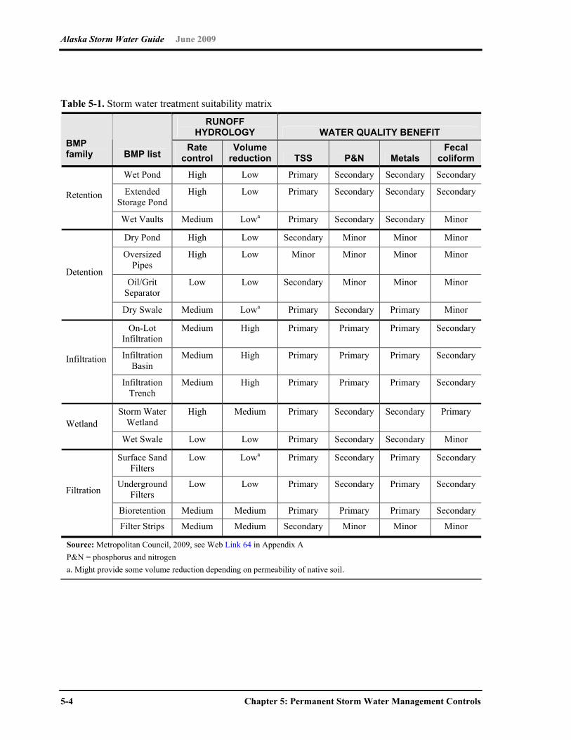
Alaska Storm Water Guide June 2009
5-4 Chapter 5: Permanent Storm Water Management Controls
Table 5-1. Storm water treatment suitability matrix
RUNOFF HYDROLOGY WATER QUALITY BENEFIT
BMP family BMP list
Rate control
Volume reduction TSS P&N Metals
Fecal coliform
Wet Pond High Low Primary Secondary Secondary Secondary
Extended Storage Pond
High Low Primary Secondary Secondary Secondary Retention
Wet Vaults Medium Lowa Primary Secondary Secondary Minor
Dry Pond High Low Secondary Minor Minor Minor
Oversized Pipes
High Low Minor Minor Minor Minor
Oil/Grit Separator
Low Low Secondary Minor Minor Minor Detention
Dry Swale Medium Lowa Primary Secondary Primary Minor
On-Lot Infiltration
Medium High Primary Primary Primary Secondary
Infiltration Basin
Medium High Primary Primary Primary Secondary Infiltration
Infiltration Trench
Medium High Primary Primary Primary Secondary
Storm Water Wetland
High Medium Primary Secondary Secondary Primary Wetland
Wet Swale Low Low Primary Secondary Secondary Minor
Surface Sand Filters
Low Lowa Primary Secondary Primary Secondary
Underground Filters
Low Low Primary Secondary Primary Secondary
Bioretention Medium Medium Primary Primary Primary Secondary
Filtration
Filter Strips Medium Medium Secondary Minor Minor Minor
Source: Metropolitan Council, 2009, see Web Link 64 in Appendix A P&N = phosphorus and nitrogen a. Might provide some volume reduction depending on permeability of native soil.
Alaska Storm Water Guide June 2009
Chapter 5: Permanent Storm Water Management Controls 5-5
5.2 Low Impact Development/Environmental Site Design Concepts
The need for traditional permanent BMPs such as infiltration basins or wet ponds can be
reduced through the use of LID or environmental site design concepts. Like other alternative
development strategies, LID seeks to control storm water at its source. Rather than moving
storm water off-site though a conveyance system, the goal of LID is to restore the natural,
pre-developed ability of an urban site to absorb storm water.
LID integrates small-scale measures distributed throughout the development site.
Constructed green spaces, native landscaping, and a variety of innovative bioretention and
infiltration techniques capture and manage storm water on-site. LID reduces peak runoff by
allowing rainwater to soak into the ground, evaporate into the air, or collect in storage
receptacles for irrigation and other beneficial uses. In areas with slow drainage or infiltration,
LID captures the first flush of runoff before excess storm water is diverted into traditional
storm conveyance systems. The result is development that more closely maintains
predevelopment hydrology. Furthermore, LID has been shown to be cost-effective, and in
some cases, less expensive than using traditional storm water management techniques.
Additional information on LID is available from a number of sources: USEPA (see Web
Link 65 in Appendix A), the Low Impact Development Center (Link 66 in Appendix A), and
the Puget Sound Action Team (Link 67 in Appendix A).
LID Techniques LID can be simple and effective. Instead of relying solely on complex and costly collection,
conveyance, storage and treatment systems, LID employs a range of economical devices
that control runoff at the source.
Bioretention cells, commonly known as rain gardens, are relatively small-scale,
landscaped depressions containing plants and a soil mixture that absorbs and filters runoff.
Cisterns and rain barrels harvest and store rainwater collected from roofs. By storing and
diverting runoff, these devices help reduce the flooding and erosion caused by storm water
runoff. And because they contain no salts or sediment, they can provide soft, chemical-free
water for garden or lawn irrigation, reducing water bills and conserving municipal water
supplies.
Green roofs are rooftops partially or completely covered with plants. Used for decades in
Europe, green roofs help mitigate the urban heat island effect and reduce peak storm water
Alaska Storm Water Guide June 2009
5-6 Chapter 5: Permanent Storm Water Management Controls
flows. The vegetated cover also protects and insulates the roof, extending its life and
reducing energy costs.
Permeable and porous pavements reduce storm water runoff by allowing water to soak
through the paved surface into the ground beneath. Permeable pavement encompasses a
variety of mediums, from porous concrete and asphalt, to plastic grid systems and
interlocking paving bricks suitable for driveways and pedestrian malls. Permeable pavement
helps reduce runoff volumes at a considerably lower cost than traditional storm drain
systems.
Dry swales are broad, open channels sown with erosion-resistant and flood-tolerant
grasses. Used alongside roadways for years primarily as storm water conveyances, swales
can slow storm water runoff, filter it and allow it to soak into the ground. Swales and other
biofiltration devices like grass filter strips improve water quality and reduce in-stream erosion
by slowing the velocity of storm water runoff before it enters the stream. Swales also cost
less to install than curbs, storm drain inlets and piping systems.
5.3 Source Control Practices for High Pollutant Source Hotspots
For some high pollutant source hotspots (e.g., some industries and commercial businesses,
such as gas stations or large parking lots—for more information, see Section 2.7), the
primary focus should be on reducing the exposure of the pollutants to storm water before
permanent storm water controls are selected. Source control practices are used to minimize
exposure of potential pollutants to storm water runoff. Examples of source control
nonstructural and structural BMPs include using less toxic chemicals and covering an
activity area that might be a pollutant source. Source control BMPs are preferred over
treatment control BMPs because they prevent pollutants from being introduced into storm
water (therefore treatment is not required to remove the pollutant), and source controls are
usually, but not always, less costly than treatment control BMPs.
Common source control practices include the following:
Housekeeping Practices
Public Education/Participation
Employee Training
Conserving Natural Areas/Vegetation Controls
Alaska Storm Water Guide June 2009
Chapter 5: Permanent Storm Water Management Controls 5-7
Protecting Slopes & Channels
Providing Storm Drain System Stenciling & Signage
Trash Storage Areas
Outdoor Material Handling and Storage Areas
Covering Loading/Unloading Dock Areas
Covering Waste Handling & Disposal
Improving Vehicle Fleet Management
Repair/Maintenance Bays
Sweeping Parking Area
Additional information on different source control BMPs for pollutant hotspots is at
California Stormwater Quality Association (CASQA) Industrial and Commercial Stormwater BMP Handbook (see Link 68 in Appendix A).
Center for Watershed Protection Pollution Source Control Practices (see Link 69 in Appendix A).

Alaska Storm Water Guide June 2009
5-8 Chapter 5: Permanent Storm Water Management Controls
5.4 Permanent Storm Water BMPs
Table 5-2 lists the feasibility of various storm water practices on the basis of the five Alaskan
climatic regions. Following this table are design adaptations for 13 common permanent
BMPs.
Table 5-2. Feasibility of storm water BMPs, based on climatic region
Alaskan climatic regions Storm water treatment practices (STP) Coastal Southcentral Western Interior Arctic
Bioretention Infiltration Filtering Practices Dry ED Ponds Constructed Wetlands Wet Ponds Green Roofs Rain Tank/Cistern Permeable Pavers Dry Swale Filter Strips Underground Feasibility symbols:
Widely feasible Might be feasible in certain situations
Feasible only with major design adaptation Infeasible and not recommended
Sources: Shannon and Wilson 2006; Extremely Cold Climate Stormwater Survey, Caraco and Claytor 1997; MOA 2007
Note: These recommendations are general guidance; site-specific conditions will dictate proper BMP selection

Alaska Storm Water Guide June 2009
Chapter 5: Permanent Storm Water Management Controls 5-9
This page intentionally left blank.
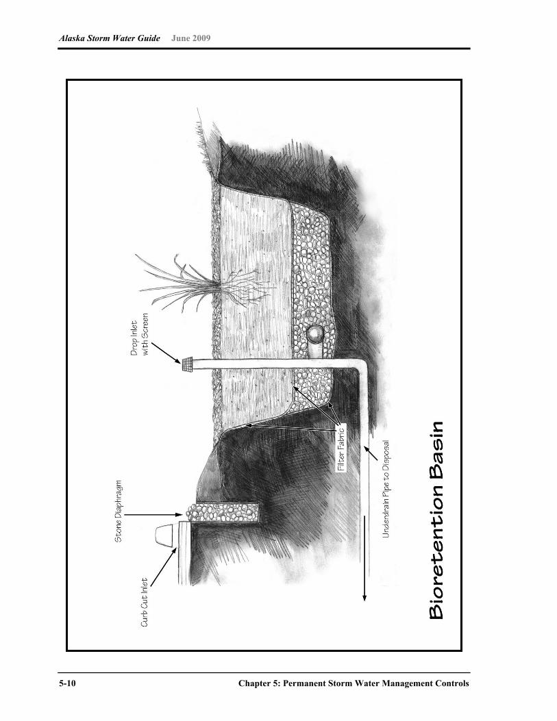
Alaska Storm Water Guide June 2009
5-10 Chapter 5: Permanent Storm Water Management Controls

Alaska Storm Water Guide June 2009
Chapter 5: Permanent Storm Water Management Controls 5-11
Bioretention Design Adaptations for Alaska
STP Alaskan climatic regions
Coastal Southcentral Western Interior Arctic
Basic Bioretention Design Adaptation for Alaska
A two-cell design is recommended, with the first cell designed as a pretreatment cell to capture sediments and the second cell designed as the bioretention filter.
Bioretention areas should be used for snow storage only if an overflow is provided and they are planted with salt-tolerant, non-woody plant species. To reduce the potential for freezing, the filter bed and underdrain pipe should be extended below the frost line, or the underdrain should be oversized by one pipe size, or both.
For a plant species list, see Web Link 70 in Appendix A. Tree and shrub locations cannot conflict with plowing and piling of snow into
storage areas. A combination of peat and sand should be used for soil media (or loamy sand or
sandy loam). The surface layer can consist of river stone or hardwood mulch.
Extreme Design
In high rainfall areas, an oversized overflow and underdrain are needed so the bioretention area does not become continuously saturated and soggy. The plant mix should be adapted to rainforest conditions.
For areas with permafrost, the filter depth can be shallow (one foot) with a 9-inch underdrain layer.
Feasibility symbols:
Widely feasible Might be feasible in certain situations
Feasible only with major design adaptation Infeasible and not recommended
Notes Performance studies show that bioretention effectively captures and treats runoff during winter
months with average daily temperatures in the –5 to 10 degree Celsius (° C) range (Traver 2005; UNH 2005). Frost penetration of filter media occurred and varied from zero to 17 cm in studies at the University of New Hampshire (Roseen 2007). While bioretention frequently captures runoff containing high chloride concentrations, the chloride will pass through without treatment.

Alaska Storm Water Guide June 2009
5-12 Chapter 5: Permanent Storm Water Management Controls

Alaska Storm Water Guide June 2009
Chapter 5: Permanent Storm Water Management Controls 5-13
Infiltration Design Adaptation for Alaska
STP Alaskan climatic regions
Coastal Southcentral Western Interior Arctic
Basic Infiltration Design Adaptation for Alaska
Infiltration practices are generally not feasible in extremely cold climates that experience permafrost.
In high precipitation zones (Climatic region A), infiltration might not be feasible in areas with shallow, saturated, nonporous soils or a prevalence of bedrock near the surface.
In less extreme climates, infiltration can work if the bottom of the practice extends below the frost line.
If the infiltration practice treats roadside runoff, a flow diversion might be desired to divert flow in the winter to prevent movement of chlorides into groundwater and to prevent clogging by road sand.
Pretreatment cells must be oversized to account for the additional sediment load caused by road sanding and sparse vegetative cover (up to 40% of the WQv).
Infiltration practices should have at least a 25-foot setback from roadways and foundations to prevent potential frost-heaving.
Infiltration should be avoided if the site is classified as a potential storm water hotspot or is within a sole-source drinking water area.
Extreme Design
For areas with permafrost, excavation should not extend to within 3 feet of the permafrost layer.
For high rainfall areas, acceptable soil infiltration rates are 1 to 4 inches per hour.
Feasibility symbols:
Widely feasible Might be feasible in certain situations
Feasible only with major design adaptation Infeasible and not recommended
Note Infiltration can be designed to withstand more moderate winter conditions. The main problem is ice forming
in the voids or the subsoils below, which could briefly cause nuisance flooding when spring melt occurs.
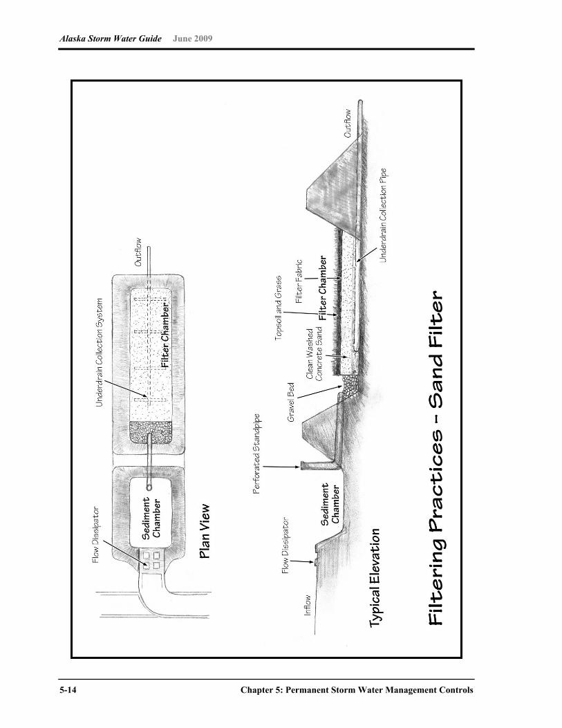
Alaska Storm Water Guide June 2009
5-14 Chapter 5: Permanent Storm Water Management Controls
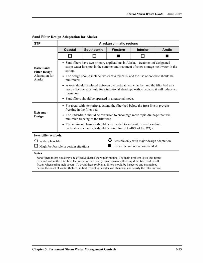
Alaska Storm Water Guide June 2009
Chapter 5: Permanent Storm Water Management Controls 5-15
Sand Filter Design Adaptation for Alaska
STP Alaskan climatic regions
Coastal Southcentral Western Interior Arctic
Basic Sand Filter Design Adaptation for Alaska
Sand filters have two primary applications in Alaska—treatment of designated storm water hotspots in the summer and treatment of snow storage melt water in the spring.
The design should include two excavated cells, and the use of concrete should be minimized.
A weir should be placed between the pretreatment chamber and the filter bed as a more effective substitute for a traditional standpipe orifice because it will reduce ice formation.
Sand filters should be operated in a seasonal mode.
Extreme Design
For areas with permafrost, extend the filter bed below the frost line to prevent freezing in the filter bed.
The underdrain should be oversized to encourage more rapid drainage that will minimize freezing of the filter bed.
The sediment chamber should be expanded to account for road sanding. Pretreatment chambers should be sized for up to 40% of the WQv.
Feasibility symbols:
Widely feasible Might be feasible in certain situations
Feasible only with major design adaptation Infeasible and not recommended
Notes Sand filters might not always be effective during the winter months. The main problem is ice that forms
over and within the filter bed. Ice formation can briefly cause nuisance flooding if the filter bed is still frozen when spring melt occurs. To avoid these problems, filters should be inspected and maintained before the onset of winter (before the first freeze) to dewater wet chambers and scarify the filter surface.
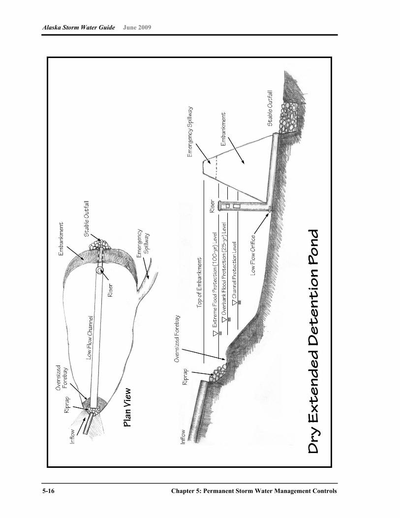
Alaska Storm Water Guide June 2009
5-16 Chapter 5: Permanent Storm Water Management Controls
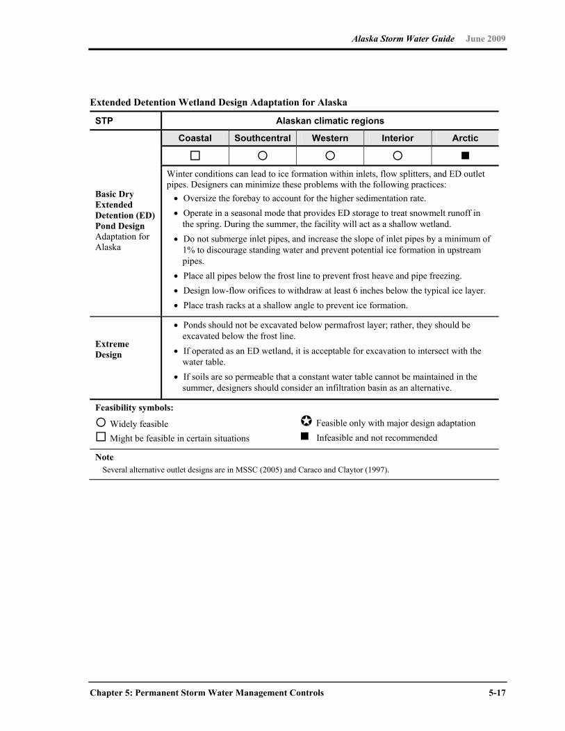
Alaska Storm Water Guide June 2009
Chapter 5: Permanent Storm Water Management Controls 5-17
Extended Detention Wetland Design Adaptation for Alaska
STP Alaskan climatic regions
Coastal Southcentral Western Interior Arctic
Basic Dry Extended Detention (ED) Pond Design Adaptation for Alaska
Winter conditions can lead to ice formation within inlets, flow splitters, and ED outlet pipes. Designers can minimize these problems with the following practices: Oversize the forebay to account for the higher sedimentation rate. Operate in a seasonal mode that provides ED storage to treat snowmelt runoff in
the spring. During the summer, the facility will act as a shallow wetland. Do not submerge inlet pipes, and increase the slope of inlet pipes by a minimum of
1% to discourage standing water and prevent potential ice formation in upstream pipes.
Place all pipes below the frost line to prevent frost heave and pipe freezing. Design low-flow orifices to withdraw at least 6 inches below the typical ice layer. Place trash racks at a shallow angle to prevent ice formation.
Extreme Design
Ponds should not be excavated below permafrost layer; rather, they should be excavated below the frost line.
If operated as an ED wetland, it is acceptable for excavation to intersect with the water table.
If soils are so permeable that a constant water table cannot be maintained in the summer, designers should consider an infiltration basin as an alternative.
Feasibility symbols:
Widely feasible Might be feasible in certain situations
Feasible only with major design adaptation Infeasible and not recommended
Note Several alternative outlet designs are in MSSC (2005) and Caraco and Claytor (1997).
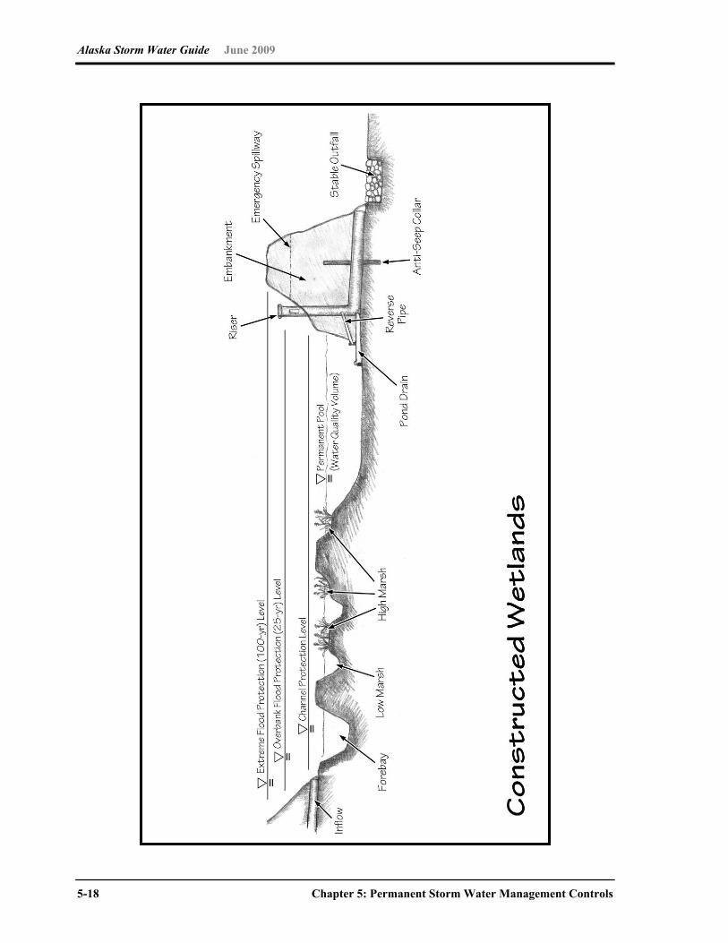
Alaska Storm Water Guide June 2009
5-18 Chapter 5: Permanent Storm Water Management Controls
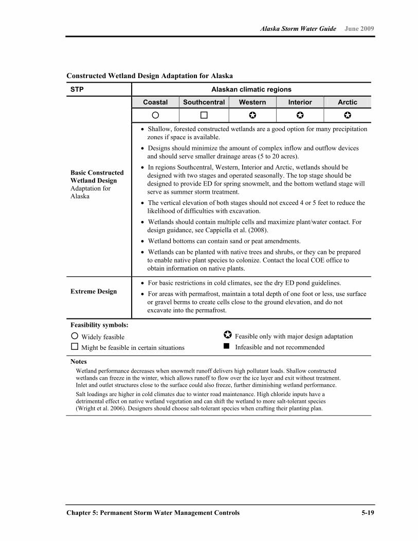
Alaska Storm Water Guide June 2009
Chapter 5: Permanent Storm Water Management Controls 5-19
Constructed Wetland Design Adaptation for Alaska
STP Alaskan climatic regions
Coastal Southcentral Western Interior Arctic
Basic Constructed Wetland Design Adaptation for Alaska
Shallow, forested constructed wetlands are a good option for many precipitation zones if space is available.
Designs should minimize the amount of complex inflow and outflow devices and should serve smaller drainage areas (5 to 20 acres).
In regions Southcentral, Western, Interior and Arctic, wetlands should be designed with two stages and operated seasonally. The top stage should be designed to provide ED for spring snowmelt, and the bottom wetland stage will serve as summer storm treatment.
The vertical elevation of both stages should not exceed 4 or 5 feet to reduce the likelihood of difficulties with excavation.
Wetlands should contain multiple cells and maximize plant/water contact. For design guidance, see Cappiella et al. (2008).
Wetland bottoms can contain sand or peat amendments. Wetlands can be planted with native trees and shrubs, or they can be prepared
to enable native plant species to colonize. Contact the local COE office to obtain information on native plants.
Extreme Design
For basic restrictions in cold climates, see the dry ED pond guidelines. For areas with permafrost, maintain a total depth of one foot or less, use surface
or gravel berms to create cells close to the ground elevation, and do not excavate into the permafrost.
Feasibility symbols:
Widely feasible Might be feasible in certain situations
Feasible only with major design adaptation Infeasible and not recommended
Notes Wetland performance decreases when snowmelt runoff delivers high pollutant loads. Shallow constructed
wetlands can freeze in the winter, which allows runoff to flow over the ice layer and exit without treatment. Inlet and outlet structures close to the surface could also freeze, further diminishing wetland performance.
Salt loadings are higher in cold climates due to winter road maintenance. High chloride inputs have a detrimental effect on native wetland vegetation and can shift the wetland to more salt-tolerant species (Wright et al. 2006). Designers should choose salt-tolerant species when crafting their planting plan.
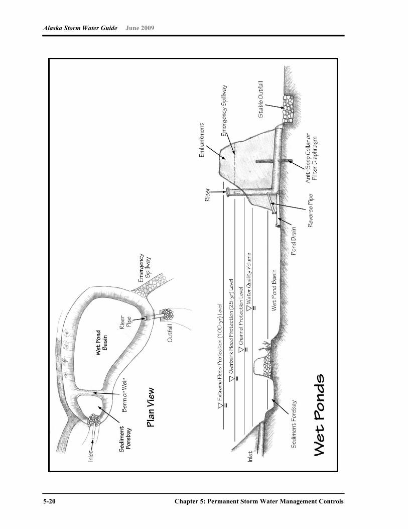
Alaska Storm Water Guide June 2009
5-20 Chapter 5: Permanent Storm Water Management Controls
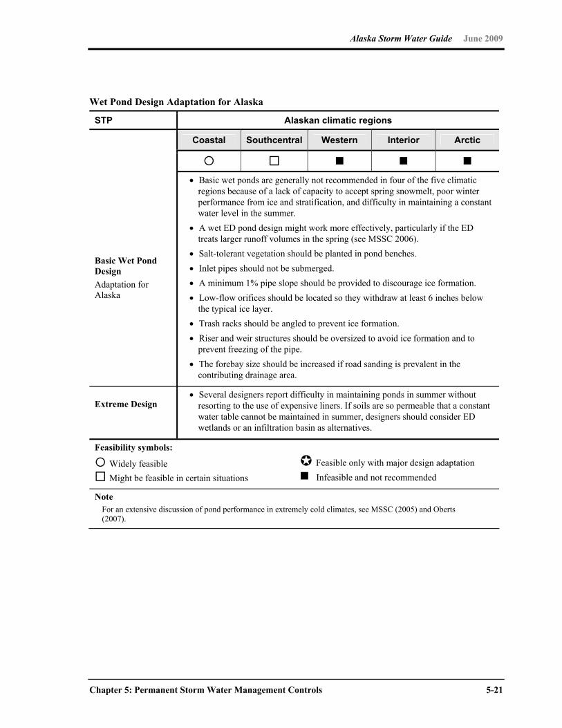
Alaska Storm Water Guide June 2009
Chapter 5: Permanent Storm Water Management Controls 5-21
Wet Pond Design Adaptation for Alaska
STP Alaskan climatic regions
Coastal Southcentral Western Interior Arctic
Basic Wet Pond Design Adaptation for Alaska
Basic wet ponds are generally not recommended in four of the five climatic regions because of a lack of capacity to accept spring snowmelt, poor winter performance from ice and stratification, and difficulty in maintaining a constant water level in the summer.
A wet ED pond design might work more effectively, particularly if the ED treats larger runoff volumes in the spring (see MSSC 2006).
Salt-tolerant vegetation should be planted in pond benches. Inlet pipes should not be submerged. A minimum 1% pipe slope should be provided to discourage ice formation. Low-flow orifices should be located so they withdraw at least 6 inches below
the typical ice layer. Trash racks should be angled to prevent ice formation. Riser and weir structures should be oversized to avoid ice formation and to
prevent freezing of the pipe. The forebay size should be increased if road sanding is prevalent in the
contributing drainage area.
Extreme Design
Several designers report difficulty in maintaining ponds in summer without resorting to the use of expensive liners. If soils are so permeable that a constant water table cannot be maintained in summer, designers should consider ED wetlands or an infiltration basin as alternatives.
Feasibility symbols:
Widely feasible Might be feasible in certain situations
Feasible only with major design adaptation Infeasible and not recommended
Note For an extensive discussion of pond performance in extremely cold climates, see MSSC (2005) and Oberts
(2007).

Alaska Storm Water Guide June 2009
5-22 Chapter 5: Permanent Storm Water Management Controls
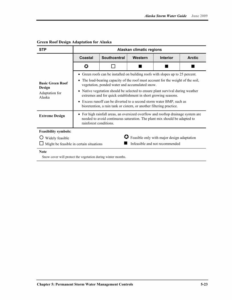
Alaska Storm Water Guide June 2009
Chapter 5: Permanent Storm Water Management Controls 5-23
Green Roof Design Adaptation for Alaska
STP Alaskan climatic regions
Coastal Southcentral Western Interior Arctic
Basic Green Roof Design Adaptation for Alaska
Green roofs can be installed on building roofs with slopes up to 25 percent. The load-bearing capacity of the roof must account for the weight of the soil,
vegetation, ponded water and accumulated snow. Native vegetation should be selected to ensure plant survival during weather
extremes and for quick establishment in short growing seasons. Excess runoff can be diverted to a second storm water BMP, such as
bioretention, a rain tank or cistern, or another filtering practice.
Extreme Design
For high rainfall areas, an oversized overflow and rooftop drainage system are needed to avoid continuous saturation. The plant mix should be adapted to rainforest conditions.
Feasibility symbols:
Widely feasible Might be feasible in certain situations
Feasible only with major design adaptation Infeasible and not recommended
Note Snow cover will protect the vegetation during winter months.
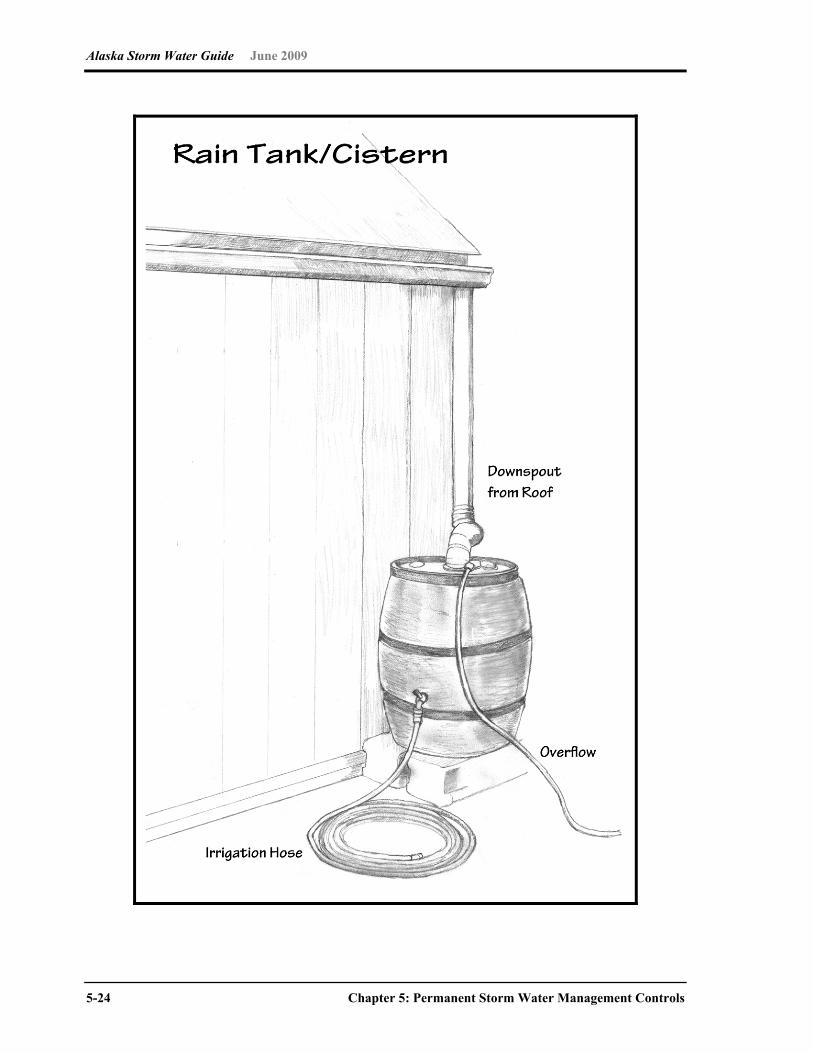
Alaska Storm Water Guide June 2009
5-24 Chapter 5: Permanent Storm Water Management Controls
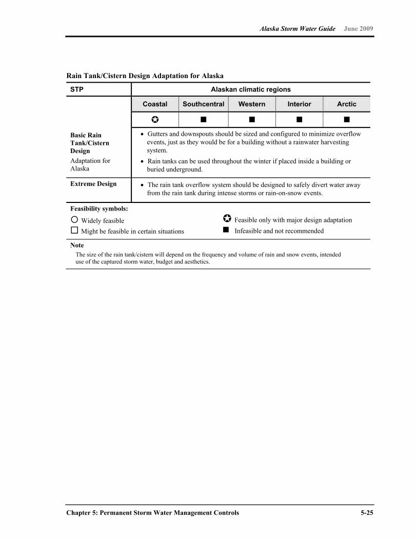
Alaska Storm Water Guide June 2009
Chapter 5: Permanent Storm Water Management Controls 5-25
Rain Tank/Cistern Design Adaptation for Alaska
STP Alaskan climatic regions
Coastal Southcentral Western Interior Arctic
Basic Rain Tank/Cistern Design Adaptation for Alaska
Gutters and downspouts should be sized and configured to minimize overflow events, just as they would be for a building without a rainwater harvesting system.
Rain tanks can be used throughout the winter if placed inside a building or buried underground.
Extreme Design
The rain tank overflow system should be designed to safely divert water away from the rain tank during intense storms or rain-on-snow events.
Feasibility symbols:
Widely feasible Might be feasible in certain situations
Feasible only with major design adaptation Infeasible and not recommended
Note The size of the rain tank/cistern will depend on the frequency and volume of rain and snow events, intended
use of the captured storm water, budget and aesthetics.

Alaska Storm Water Guide June 2009
5-26 Chapter 5: Permanent Storm Water Management Controls
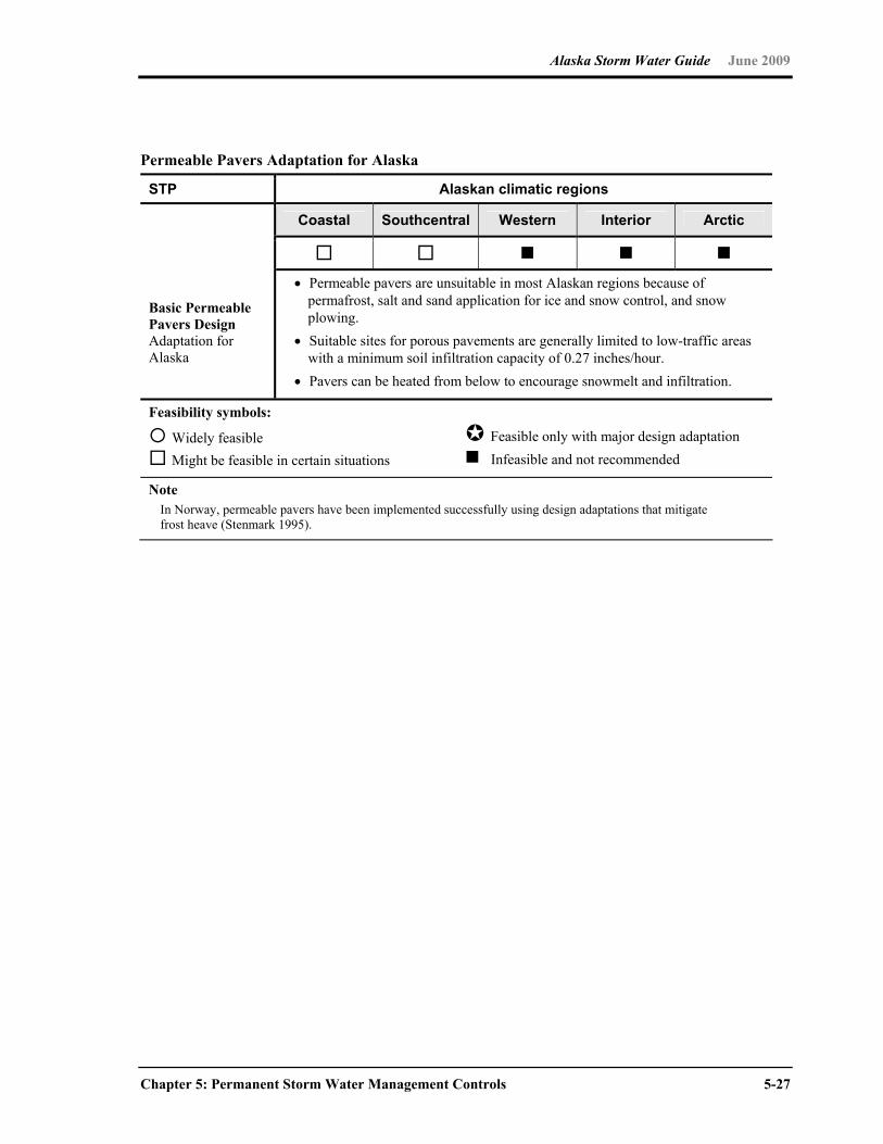
Alaska Storm Water Guide June 2009
Chapter 5: Permanent Storm Water Management Controls 5-27
Permeable Pavers Adaptation for Alaska
STP Alaskan climatic regions
Coastal Southcentral Western Interior Arctic
Basic Permeable Pavers Design Adaptation for Alaska
Permeable pavers are unsuitable in most Alaskan regions because of permafrost, salt and sand application for ice and snow control, and snow plowing.
Suitable sites for porous pavements are generally limited to low-traffic areas with a minimum soil infiltration capacity of 0.27 inches/hour.
Pavers can be heated from below to encourage snowmelt and infiltration.
Feasibility symbols:
Widely feasible Might be feasible in certain situations
Feasible only with major design adaptation Infeasible and not recommended
Note In Norway, permeable pavers have been implemented successfully using design adaptations that mitigate
frost heave (Stenmark 1995).

Alaska Storm Water Guide June 2009
5-28 Chapter 5: Permanent Storm Water Management Controls
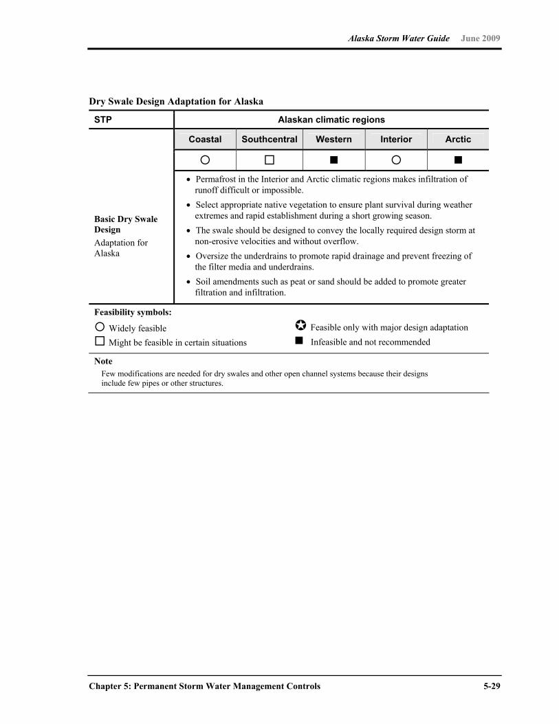
Alaska Storm Water Guide June 2009
Chapter 5: Permanent Storm Water Management Controls 5-29
Dry Swale Design Adaptation for Alaska
STP Alaskan climatic regions
Coastal Southcentral Western Interior Arctic
Basic Dry Swale Design Adaptation for Alaska
Permafrost in the Interior and Arctic climatic regions makes infiltration of runoff difficult or impossible.
Select appropriate native vegetation to ensure plant survival during weather extremes and rapid establishment during a short growing season.
The swale should be designed to convey the locally required design storm at non-erosive velocities and without overflow.
Oversize the underdrains to promote rapid drainage and prevent freezing of the filter media and underdrains.
Soil amendments such as peat or sand should be added to promote greater filtration and infiltration.
Feasibility symbols:
Widely feasible Might be feasible in certain situations
Feasible only with major design adaptation Infeasible and not recommended
Note Few modifications are needed for dry swales and other open channel systems because their designs
include few pipes or other structures.

Alaska Storm Water Guide June 2009
5-30 Chapter 5: Permanent Storm Water Management Controls

Alaska Storm Water Guide June 2009
Chapter 5: Permanent Storm Water Management Controls 5-31
Basic Filter Strip Design Adaptations for Alaska
STP Alaskan climatic regions
Coastal Southcentral Western Interior Arctic
Basic Filter Strip Design Adaptation for Alaska
The maximum contributing sheet flow path from adjacent pervious areas should not exceed 150 feet.
The maximum contributing sheet flow path from adjacent impervious areas should not exceed 75 feet.
The contributing flow path should not have a slope greater than 3% for any 50-foot segment.
Runoff should enter the boundary of the filter strip as sheet flow for the one-inch storm.
A depression, berm or level spreader can be used to spread out concentrated flows generated during larger storm events.
Extreme Design In areas with permafrost, infiltration will be limited, reducing the effectiveness
of the filter strip. In areas of high rainfall, level spreading measures are essential to prevent
erosion from concentrated flows.
Feasibility symbols:
Widely feasible Might be feasible in certain situations
Feasible only with major design adaptation Infeasible and not recommended
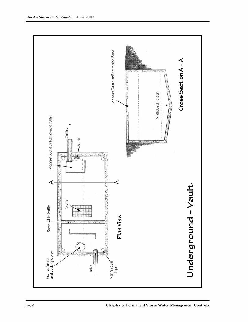
Alaska Storm Water Guide June 2009
5-32 Chapter 5: Permanent Storm Water Management Controls
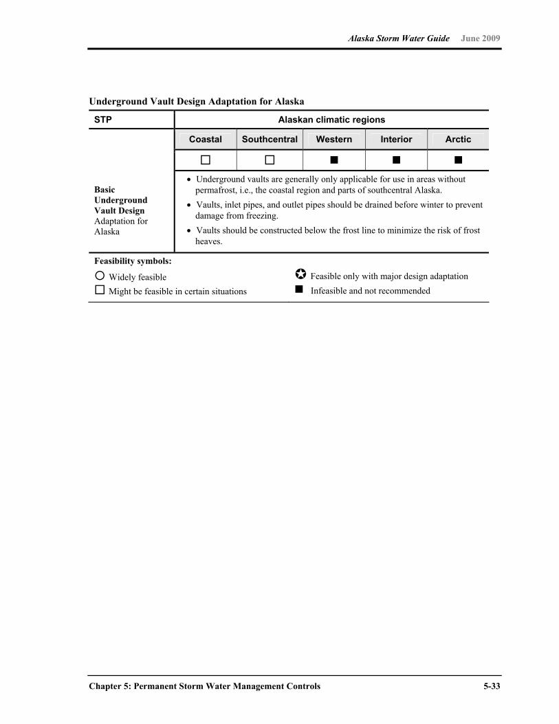
Alaska Storm Water Guide June 2009
Chapter 5: Permanent Storm Water Management Controls 5-33
Underground Vault Design Adaptation for Alaska
STP Alaskan climatic regions
Coastal Southcentral Western Interior Arctic
Basic Underground Vault Design Adaptation for Alaska
Underground vaults are generally only applicable for use in areas without permafrost, i.e., the coastal region and parts of southcentral Alaska.
Vaults, inlet pipes, and outlet pipes should be drained before winter to prevent damage from freezing.
Vaults should be constructed below the frost line to minimize the risk of frost heaves.
Feasibility symbols:
Widely feasible Might be feasible in certain situations
Feasible only with major design adaptation Infeasible and not recommended
Alaska Storm Water Guide June 2009
5-34 Chapter 5: Permanent Storm Water Management Controls
5.5 Maintenance
Proper BMP operation and maintenance (O&M) is an important aspect in assuring the
effectiveness of a BMP in mitigating storm water pollution. Routine maintenance or service
also contributes to the efficiency and continuous operation of the system. To ensure the
effectiveness of permanent, structural BMPs, an O&M plan should be developed and
implemented. The O&M plan can be developed by the project operator or according to the
BMP manufacturer’s manual.
The O&M plan describes how the owner can ensure performance of the BMP over time.
O&M plans should specify the following:
The scope of maintenance activities to be performed at the facilities
The schedule for performing various maintenance tasks
The schedule for inspection by the facility owner
The parties responsible for inspection and maintenance of the facility
Instructions on the proper O&M of the BMPs should be provided to the developer, owner or
responsible entities (e.g., homeowners’ associations, employees, tenants or subdivision
managers) to ensure adequate and appropriate O&M of the system. The O&M plan should
be kept on-site for inspection. Maintenance of the BMP is typically the responsibility of the
facility’s owner or operator or both.
A log should be kept on-site, where practical, to record inspection and maintenance activities.
The record should contain the following information: (1) type of maintenance activities or
source-control practices, (2) date the activities are completed, and (3) the name of operator
performing the activities. During transfer of ownership/operation of the facility, the current
owner should notify the new owner/operator of these conditions and required activities.
Some typical maintenance activities for permanent BMPs include
Cleaning and removing debris
Mowing vegetation
Repairing animal burrows
Removing sediment
Repairing outlets, risers, or other structures
Reseeding
Alaska Storm Water Guide June 2009
Glossary-1
Glossary
A
adsorption the adhesion of an extremely thin layer of molecules to the surfaces of solid
bodies or liquids with which they are in contact
aggrade the buildup of sediment or eroded material
anaerobic condition operating in a system in which there is the absence of free oxygen
available for biologic use
animal waste management practices and procedures that prevent the movement of animal
wastes or byproducts from feeding or holding areas into the wider environment
annual load quantity of pollutants, sediment, or nutrients carried by a waterbody over the
period of a year
antecedent soil moisture the water content held by a soil before a storm event; this has an
effect on the amount of water that will run off as a result of that event
B
bankfull flow in a stream or river where the water level is to the top of its bank; considered
to be the channel forming flow and has a recurrence interval of around 2.5 years
bank stabilization activities undertaken to shore up or ensure the integrity of a stream or
river bank and protect it from erosion and slumping
base flow the flow coming from ground water inputs to a stream or river system
basin a depression in the surface of the land that holds water
bed load the sand, gravel or rocks that are transported along the stream bottom by traction,
rolling, sliding or saltation
Alaska Storm Water Guide June 2009
Glossary-2
Best Management Practice (BMP) one of many different structural or nonstructural
methods used to prevent pollution or to treat runoff, including such diverse measures as
ponding, street sweeping, filtration through a rain garden and infiltration to a gravel trench
biochemical oxygen demand (BOD) a measure of the amount of oxygen required to
biologically degrade organic matter in the water
bioretention a soil and plant–based storm water management best management practice
(BMP) used to filter runoff
buffers a vegetative setback between development and streams, lakes and wetlands whose
aim is to physically protect and separate the resource from future disturbance or
encroachment
C
catch basin an inlet to the storm drain system that typically includes a grate or curb inlet
channel protection actions taken to prevent habitat degradation and erosion that can
cause downstream enlargement and incision in urban streams due to increased frequency
of bankfull and sub–bankfull stormwater flows
chemical controls includes such activities as salt management, fertilizer/pesticide
management, and spill prevention and containment
cistern a receptacle for holding liquids, usually water; often built to catch and store
rainwater
cluster design a reduction of average lot size within a residential development in exchange
for greater conservation of natural areas
cold climate sizing sizing of stormwater practices to accommodate snowmelt (typically a
larger than rainfall–based criteria sizing because snowmelt represents more than 10 percent
of annual precipitation)
computable pollutant a pollutant for which enough runoff concentration and BMP
performance data is available to perform a site–based pollutant load calculation
documenting no increase in loading
Alaska Storm Water Guide June 2009
Glossary-3
conservation easement a restriction placed on a piece of property to protect the resources
associated with the parcel; the easement is either voluntarily sold or donated by the
landowner and constitutes a legally binding agreement that prohibits certain types of
development from taking place on the land
construction sequencing a specified work schedule that coordinates the timing of land–
disturbing activities and the installation of erosion–protection and sedimentation–control
measures
conveyance a structure or feature used for transferring water from one location to another
curb and gutter system edging along the side of streets meant to quickly convey storm
water runoff from the street and adjacent areas into the storm water system
curve number an index combining hydrologic soil group, land use factors, treatment and
hydrologic condition that is used in a method developed by the Soil Conservation Service to
determine the approximate amount of runoff from a rainfall event in a particular area;
typically used in Low Impact Development calculations
D
dead storage the permanent storage volume of a pond
degrade downcutting where softer material is present in a stream channel
design storm streamflow from a storm event used as a standard for which performance of
storm water management practices are measured
detention time the theoretical calculated time that a prescribed amount of water is held in a
settling basin
disconnection technique to spread runoff generated from rooftops or impervious surfaces
into adjacent pervious areas where it can be filtered and infiltrated
drainageway a course or channel along which water moves in draining an area
dry pond a water bearing storm water management facility that controls peak runoff flows to
receiving bodies such as rivers and streams that is typically free of water during dry periods,
but filled during times of rainfall

Alaska Storm Water Guide June 2009
Glossary-4
dry well a deep covered hole acting as an underground storage facility for storm water until
it seeps into the surrounding soil
dry swale a grassed channel that primarily served to transport stormwater runoff away from
roadways and rights-of-way and provides some treatment of storm water facilitating
infiltration
E
elution washing out of ions in solution from a snowpack
erosion the wearing down or washing away of the soil and land surface by the action of
water, wind or ice
erosion control any efforts to prevent the wearing or washing away of the soil or land
surface
erosion control blanket a natural or geotextile mat placed in areas susceptible to erosion
to hold the soil in place until it can be permanently stabilized through vegetation or armoring
eutrophic an environment that has an excessive concentration of nutrients
evaporation the process of changing from a liquid state into a gas
evapotranspiration loss of water to the atmosphere as a result of the joint processes of
evaporation and transpiration through vegetation
event–based load quantity of pollutants, sediment or nutrients carried by a waterbody for
particular magnitude storm events
exfiltration uncontrolled outward leakage through cracks and interstices
extended detention provides temporary storage of storm water which attenuates peak
flows and because extended detention basins are normally designed as multistage facilities,
they promote the settling of pollutants.
extreme event an 100–year, 24–hour rain event or an 100–year, 10–day snowmelt event or
greater

Alaska Storm Water Guide June 2009
Glossary-5
extreme flood control for the 100–year, 24–hour or larger events, to maintain the
boundaries of the predevelopment 100–year floodplain, reduce flooding risks to life, reduce
property damage and protect the physical integrity of the storm water management
practices.
F
floodplain land adjacent to a waterbody that is inundated when the discharge exceeds the
conveyance capacity of the normal channel (often defined in a regulatory sense as the
extent of the 100–year flood)
flow control controlling the rate and volume of water leaving a site
forebay an extra storage space or small basin near the inlet to settle out incoming
sediments before water moves on into a pond or detention area
freeze–thaw cycle the alternation between freezing and thawing in the snowpack. This
cycle changes the composition and characteristics of the snowpack and can affect its
pollutant carrying ability and the amount of runoff generated
frequency curve A derivative of the probability curve that expresses the relation between
the frequency distribution plot, with the magnitude of the variables on one axis and the
number of occurrences of each magnitude in a given period as the other
frost heave a phenomenon in cold areas in which water that is trapped in soil or cracks in
rocks alternately freezes and thaws; this causes the water to expand and contract, which
can cause significant movement and upheaval of the soil or rock
G
geomorphology the study of the form and development of the landscape
global warming the progressive gradual rise of the earth’s surface temperature thought to
be caused by the greenhouse effect, which could be responsible for changes in global
climate patterns
grass channels a natural open channel conveyance system which is preferable to curb and
gutter where development density, soils and slopes permit
Alaska Storm Water Guide June 2009
Glossary-6
green roof a rooftop treatment practice in which a thin planting media is established on roof
surfaces and then planted with hardy, low–growing vegetation
ground water water occupying the sub–surface saturated zone
gully erosion the widening, deepening and head cutting of small channels and waterways
(rills) due to erosion by water or snowmelt, typified by channels one foot or more deep
H
head the difference in elevation between two points in a body of water and the resulting
pressure of the fluid at the lower point
hotspot a concentrated source of potential storm water pollution generating land uses such
as gas stations, chemical storage facilities, industrial facilities and so on
housekeeping (BMP) any of a number of BMPs designed to keep pollutants from entering
the waste stream by maintaining clean conditions, including street sweeping, litter pickup
and animal cleanup
hydrograph graphical representation of stage or discharge at a point in a drainage as a
function of time
hyetograph a graphical representation of the distribution of rainfall over the total duration of
a storm event
hydrology the science dealing with the properties, distribution and circulation of water
hydroperiod the length of time an area is inundated or saturated by water
I
impaired waters streams or lakes that do not meet their designated uses because of
excess pollutants or identified stressors
impervious surface a surface in the landscape that impedes the infiltration of rainfall and
results in an increased volume of surface runoff
infiltration flow of water from the land surface into the subsurface
Alaska Storm Water Guide June 2009
Glossary-7
industrial materials or activities include but are not limited to material handling equipment
or activities, industrial machinery, raw materials, intermediate products, by-products, final
products or waste products
inlet protection preservation of the integrity and protection from the erosion of the area
where water enters into a treatment area usually by vegetation or armoring
intensity–duration–frequency curves (IDF) graphical representation of the intensity,
duration and frequency of a differing rainfalls over time
J
K
L
live storage the portion of a storage basin or reservoir that is at or above the outlet and
used for temporary water storage
low density residential a low concentration of housing units in a specific area or on a
specific property, typical of rural areas
low impact development (LID) the application of nonstructural practices at residential and
commercial sites to reduce impervious cover, conserve natural areas and use pervious
areas to more effectively treat stormwater runoff; LID hydrology can be tied to the SCS
curve number
M
minimum control measures six required components of the SWMP for Phase II MS4
communities. The six minimum control measures are: public education/outreach; public
participation/involvement; illicit discharge detection and elimination; construction site runoff
control; post–construction site runoff control; and pollution prevention/good housekeeping.
municipal separate storm sewer system (MS4) a conveyance or system of conveyances
owned or operated by a state, city, town, county, district, association or other public body
having jurisdiction over disposal of sewage, industrial wastes, storm water or other wastes
that discharges to waters of the United States; they are required to develop and implement a
Storm Water Management Program
Alaska Storm Water Guide June 2009
Glossary-8
muskeg an acidic soil type common in arctic and boreal areas. Muskeg consists of dead
plants in various states of decomposition (as peat), ranging from fairly intact sphagnum
moss, to sedge peat, to highly decomposed muck. Pieces of wood such as buried tree
branches can make up 5 to 15 percent of the peat soil. Muskeg tends to have a water table
very near the surface. The sphagnum moss forming it can hold 15 to 30 times its own weight
in water, allowing the spongy wet muskeg to form even on sloping ground.
N
native vegetation plants that are adapted to and occur naturally in a specific location
natural area conservation the identification and protection of natural resources and
features that maintain the predevelopment hydrology at a site by reducing runoff, promoting
infiltration and preventing soil erosion.
no exposure all industrial materials or activities are protected by a storm resistant shelter to
prevent exposure to rain, snow, snowmelt or runoff
nonpoint source pollution pollution that enters a waterbody from diffuse origins on the
watershed and does not result from discernable, confined or discrete conveyances
O
Ordinary High Water (OHW) 11 AAC 53.120. Technical Survey Standards (2) Ordinary
High Water Mark. This is to be determined by observing and marking the place on the bank
or shore up to which the presence and action of water are so prolonged as to impress on the
bank or shore a character distinct from that of the bank or shore with respect to vegetation
and the nature of the soil. 11 AAC 53.900. Definitions (23) “ordinary high water mark” means
the mark along the bank or shore up to which the presence and action of the nontidal water
are so common and usual, and so long continued in all ordinary years, as to leave a natural
line impressed on the bank or shore and indicated by erosion, shelving, changes in soil
characteristics, destruction of terrestrial vegetation, or other distinctive physical
characteristics.
P
peak flow control controlling the timing and magnitude of the largest flow either leaving the
site or flowing through the watershed using storm water management techniques to avoid
flooding and damage downstream.
Alaska Storm Water Guide June 2009
Glossary-9
permanent storage pool the volume in a pond or reservoir below the lowest outlet level,
designed for water quality purposes to settle out particles and nutrients
permeable paver a range of products that enable some fraction of rainfall to be infiltrated
into a sub–base underneath the paver
pollution load the product of flow volume times pollutant concentration
pollution prevention practices proactive activities and strategies instituted to avoid
introducing pollution into the environment
pollutograph graphical representation of pollution at a point in a drainage as a function of
time
Q
R
rainfall distribution describes how the rain fell in a 24–hour period, i.e., whether the
precipitation occurred over a 1–hour period or over the entire 24–hour period
rainfall frequency spectrum describes the average frequency of the depth of precipitation
events (adjusted for snowfall) that occur during a normal year
rain garden a landscaping feature that is planted with native perennial plants and is used to
manage storm water runoff from impervious surfaces such as roofs, sidewalks and parking
lots
recharge the addition of water to an aquifer by natural infiltration or artificial means
redevelopment any construction, alteration, or improvement that disturbs greater than or
equal to 5,000 square feet of existing impervious cover performed on sites where the
existing land use is commercial, industrial, institutional or residential
retention maintaining a permanent pool with additional freeboard for storage in a storm
water basin
retrofit the introduction of a new or improved storm water management element where it
either never existed or did not operate effectively
Alaska Storm Water Guide June 2009
Glossary-10
return interval the inverse probability that a certain flow will occur; it represents a mean
time interval based on the distribution of flows over a period of record
rill erosion an erosion process in which numerous small channels several inches deep are
formed
riparian areas areas adjacent to a waterbody acting as transition zones between terrestrial
and aquatic systems
runoff the portion of rainfall or snowmelt not immediately absorbed into the soil that drains
or flows off the land and becomes surface flow
runoff management techniques, practices and strategies for dealing with runoff and
minimizing its effect on the greater environment
S
Soil Conservation Service (SCS) Curve Number a simple, widely used method for
determining the approximate amount of runoff from a rainfall or snowmelt even in a
particular area. The curve number is based on the area's hydrologic soil group, land use,
treatment and hydrologic condition.
sediment any particulate matter that can be transported by fluid flow and that eventually is
deposited as a layer of solid particles on the bed or bottom of a body of water
sediment removal the removal, usually by settling or filtering, of suspended sediments from
the water column
settleable solids are the particulates that settle out of a still fluid
settling basins remove fine particles from water by means of gravity or decanting
silt fence a fence constructed of wood or steel supports and either natural (e.g., burlap) or
synthetic fabric stretched across an area of non–concentrated flow during site development
to trap and retain on–site sediment due to rainfall runoff
site constraints conditions unique to the site that that serve to restrain, restrict or prevent
the implementation of proposed or desired design features

Alaska Storm Water Guide June 2009
Glossary-11
slope stabilization activities or techniques employed to maintain the integrity or stop the
degradation of sloped areas
small storm hydrology study of the effects of the less than 10–year event
snowmelt the sudden release of accumulated snow and ice with the advent of warm
weather
snowpack a horizontally layered accumulation of snow from snowfall events that
accumulates and persists through the winter and can be modified by meteorological
conditions over time
spring snowmelt event large amount of melting of the winter’s accumulated snow over a
short period of time (~2 weeks); large flow volumes are typical and can be the critical water
quality design event
stage the height of a water surface above an established reference point
storm distribution a measure of how the intensity of rainfall varies over a given period of
time
storm water water that is generated by rainfall or snowmelt that causes runoff and is often
routed into drain systems for treatment or conveyence
storm water pollution prevention plan (SWPPP) a plan for preventing or minimizing
pollution generated at construction sites or industrial sites
storm water management program (SWMP) a program that MS4s must develop to control
the pollutants in storm water to the maximum extent practicable
storm water treatment train a series of storm water management practices incorporating
aspects of pollution prevention, volume control and water quality controls
streambank stabilization activities or techniques employed to maintain the integrity or stop
the degradation of streambanks due to erosion and sedimentation
sublimation the process of transforming from a solid directly into a gas without passing
through a liquid phase
Alaska Storm Water Guide June 2009
Glossary-12
subwatershed a subdivision based on hydrology corresponding to a smaller drainage area
within a larger watershed
swale a wide, shallow, vegetated depression in the ground designed to channel drainage of
water
T
Technical Publication 47 (TP–47) U.S. Weather Bureau publication that is the standard
reference for frequency analysis in Alaska
Technical Release Number 20 (TR–20) a single–event, rainfall–runoff computer model
developed by the U.S. Soil Conservation Service in 1964
Technical Release Number 55 (TR–55) a simplified procedure to calculate storm runoff,
volume, peak rate of discharge, hydrographs and storage volumes developed by the U.S.
Natural Resources Conservation Service in 1975
temporary construction sediment control techniques practices employed on an active
construction site to control movement of sediment within or off of the site until permanent
vegetation or sediment controls can be established
thermal impact the effect on streams and waterbodies of storm water runoff addition that
are higher in temperature than the ambient stream or waterbody temperature; it causes
stress or can result in the death of temperature–sensitive organisms such as trout
thermal protection techniques and practices such as infiltration and shading that act to
preserve and protect the ambient temperatures of streams and waterbodies from
temperature–raising effects of stormwater runoff and to temperature drops that lead to icing
and glaciation when ambient air temperatures are below freezing
total maximum daily load (TMDL) the amount of a pollutant from both point and nonpoint
sources that a waterbody can receive and still meet water quality standards
total phosphorus (TP) a nutrient that can also be a contaminant because of its use by
nuisance algae
total suspended solids (TSS) a measure of the amount of particulate material in
suspension in a water column
Alaska Storm Water Guide June 2009
Glossary-13
transpiration the passage of water vapor into the atmosphere through the vascular system
of plants
trash rack a structural device used to prevent debris from entering a pipe spillway or other
hydraulic structure
treatment any method, technique or practice used for management purposes
trench a long steep–sided depression in the ground used for drainage or infiltration
turbidity the cloudy appearance of water caused by the presence of suspended and
colloidal matter
U
ultra–urban highly developed urban land that has limited space and disturbed soils
under drain an underground drain or trench with openings through which the water can
percolate from the soil or ground above
unified sizing criteria statewide criteria for the sizing of storm water management systems
urbanized area per the 2000 census has a population density of more than 1,000 people
per square mile
V
vegetative filters the removal of sediment, nutrients or pollutants by plant structures
volume control controlling the overall volume or amount of storm water that is released
from a site or localized holding area into the larger conveyance system
W
water balance a hydrological formula used by scientists and land managers to determine
water surpluses and deficits in a given area; it includes inputs such as precipitation; outputs
such as evapotranspiration, infiltration and runoff; and storage within the system

Alaska Storm Water Guide June 2009
Glossary-14
water quality volume is a water quality-based approach of capturing and treating the 90
percent storm, as defined by an analysis of a local rainfall frequency spectrum, that
optimizes runoff capture resulting in high load reduction for many storm water pollutants
watershed a topographically defined area within which all water drains to a particular point
waters of the state All streams, lakes, ponds, marshes, watercourses, waterways, wells,
springs, aquifers, irrigation systems, drainage systems and all other bodies or accumulations
of water surface or underground, natural or artificial, public or private, that are contained
within, flow through or under the state or any portion thereof
waters of the United States those waters coming under federal jurisdiction
weir a spillover dam–like device used to measure or control water flow
wellhead protection area an identified area with restricted or modified land use practices
designed to protect the well supply area from the introduction of contaminants
wetland land that is transitional between aquatic and terrestrial ecosystems and must have
a predominance of hydric soils, be inundated or saturated by surface water or ground water
at a frequency and duration sufficient to support a prevalence of hydrophytic vegetation
typically adapted for life in saturated soil conditions, and under normal circumstances
support a prevalence of hydrophytic vegetation (to be a wetland the area must meet wetland
criteria for soils, vegetation and hydrology as outlined in the 2007 U.S. Army Corps of
Engineers Wetland Delineation Manual, Supplement for Alaska)
wetland systems hydrologically interconnected series of wetlands that includes the
interrelatedness of habitat, wetland functions and biology
wet pond a permanent pool of water for treating incoming storm water runoff
XYZ
Alaska Storm Water Guide June 2009
References-1
References
ACIAC (Alaska Climate Impact Assessment Commission). 2008. Final Commission Report.
Alaska State Legislature, Juneau, AK
ADEC (Alaska Department of Environmental Conservation). 2003a. Wetland Functional
Assessment Guidebook, Operational Draft Guidebook for Assessing the Functions of
Slope/Flat Wetland Complexes in the Cook Inlet Basin Ecoregion, Alaska, Using the
HGM Approach. Juneau, AK.
ADEC (Alaska Department of Environmental Conservation). 2003b. Wetland Functional
Assessment Guidebook Operational Draft Guidebook for Assessing the Functions of
Riverine and Slope River Proximal Wetlands in Coastal Southeast & Southcentral
Alaska Using the HGM Approach. Juneau, AK.
ADEC (Alaska Department of Environmental Conservation) and USGS (U.S. Geological
Survey). 1999. Draft Guidebook for Reference Based Assessment of the Functions of
Precipitation-Driven Wetlands on Discontinuous Permafrost in Interior Alaska.
Operational Draft Guidebook for Reference Based Assessment of the Functions of
Precipitation-Driven Wetlands on Discontinuous Permafrost in Interior Alaska.
Anchorage, AK.
ADOT&PF (Alaska Department of Transportation and Public Facilities). 1995. Alaska
Highway Drainage Manual.
<http://www.dot.state.ak.us/stwddes/desbridge/pop_hwydrnman.shtml>. Accessed April
2008.
ADOT&PF (Alaska Department of Transportation and Public Facilities). 2001. Alaska
Highway Drainage Manual—Chapter 16 Erosion and Sediment Control. Alaska
Department of Transportation and Public Facilities.
<http://www.dot.state.ak.us/stwddes/desbridge/pop_hwydrnman.shtml>. Accessed June
2008.
ADOT&PF (Alaska Department of Transportation and Public Facilities). 2005. Alaska Storm
Water Pollution Prevention Plan Guide. Alaska Department of Transportation and Public
Facilities, Juneau, AK.

Alaska Storm Water Guide June 2009
References-2
Brakensiek, D.L., and W.J. Rawls. 1983. Agricultural Management Effects on Soil Water
Processes, Part I: Green and Ampt Parameters for Crusting Soils. Transactions of the
American Society of Agricultural Engineers 26(6):1751–1757.
Cappiella, K., L. Fraley-McNeal, M. Novotney and T. Schueler. 2008. The next generation of
storm water wetlands. in Wetlands and Watersheds Article No. 5. Center for Watershed
Protection. Ellicott City, MD.
Caraco, D. and R. Claytor. 1997. Stormwater BMP Design Supplement for Cold Climates.
Center for Watershed Protection. Ellicott City, MD.
CWP (Center for Watershed Protection). 1998. Better Site Design: A Handbook for
Changing Development Rules in Your Community. Ellicott City, MD
CWP (Center for Watershed Protection). 2000. Impacts of Urbanization on Receiving
Waters. Draft. Prepared for USEPA by the Center for Watershed Protection, Ellicott City,
MD, under subcontract to Tetra Tech, Inc., Fairfax, VA.
CWP (Center for Watershed Protection). 2003. Impacts of Impervious Cover on Aquatic
Systems. Center for Watershed Protection, Ellicott City, MD
Cole, H. 2007. The economic impact and consequences of global climate change on
Alaska’s infrastructure. University of Alaska-Fairbanks, Fairbanks, AK.
COE (U.S. Army Corps of Engineers). 2007. Regional Supplement to the Corps of
Engineers Wetland Delineation Manual: Alaska Region (Version 2.0) U.S. Army Corps of
Engineers ERDC\EL TR-07-24. U.S. Army Corps of Engineers, Vicksburg, MS.
CSN (Chesapeake Stormwater Network). 2009. Bay-wide Stormwater Design Specification
No. 13. Constructed Wetlands.Version 2.0. Chesapeake Stormwater Network, Baltimore,
MD. <www.chesapeakestormwater.net>. Accessed April 2009.
Duluth Streams. 2008. Lake Superior Duluth Streams – Understanding Impact: Pollutants.
http://duluthstreams.org/understanding/pollutants/runoff.html. Accessed April 25, 2008.
Ferrians, Jr, O.J., R. Kachadoorian, and G.W. Greene. 1969. Permafrost and Related
Engineering Problems in Alaska. U.S. Geological Survey Professional Paper 678. U.S.
Geological Survey, Reston, VA.

Alaska Storm Water Guide June 2009
References-3
Federal Highway Administration. 2004. Evaluation of Stormwater Treatment in Constructed
Wetlands in Alaska. Federal Highway Administration. FHWA-AK-RD-03-06.
Gallant, A.L., E.F. Binnium, J.M. Omernik, and M.B. Shasby. 1995. Ecoregions of Alaska.
U.S. Geological Survey Professional Paper 1567. U.S. Geological Survey, Reston, VA.
Hirschman, D.J. and J. Kosco. 2008. Managing Stormwater in Your Community: A Guide for
Building an Effective Post-Construction Program. Center for Watershed Protection and
Tetra Tech, Inc. Ellicott City, MD. July 2008.
Iowa. 2007. Iowa Stormwater Management Manual, Version 1. Iowa State University, Center
for Transportation Research and Education. Ames. IA.
Larsen, P. and S. Goldsmith. 2007. How much might climate change add to future costs for
public infrastructure? UA Research Summary. No. 8. Institute of Social and Economic
Research. University of Alaska-Anchorage, Anchorage, AK.
Local Ordinances Governing Nonpoint Source Pollution in Alaska. Nonpoint source
municipal sources.
http://www.dced.state.ak.us/dca/nonpoint/ordinances.cfm?type=Hy. Accessed June
2009.
MDE (Maryland Department of the Environment). 2000. Stormwater Design Manual. Volume
1. Sediment and Stormwater Division. Maryland Department of the Environment,
Annapolis, MD.
Metropolitan Council. 2009. Minnesota Urban Small Sites BMP Manual: Stormwater Best
Management Practices for Cold Climates. St. Paul, MN.
Miller, J.F. 1963. Probable Maximum Precipitation and Rainfall-Frequency Data for Alaska,
Technical Paper No. 47. U.S. Department of Commerce, U.S. Weather Bureau,
Washington, DC. <http://www.wrcc.dri.edu/cgi-bin/cliMAIN.pl?ak4546>.
Accessed March 14, 2008.
MSSC (Minnesota Stormwater Steering Committee). 2006. Cold Climate Impacts on Runoff
Management. Chapter 9 in Minnesota Stormwater Manual.. Minnesota Pollution Control
Agency. St. Paul, MN.
Alaska Storm Water Guide June 2009
References-4
MSSC (Minnesota Stormwater Steering Committee). 2008. Minnesota Stormwater Manual,
2008, Version 2. <http://www.pca.state.mn.us/water/stormwater/stormwater-
manual.html>. Accessed February 2009.
MPCA (Minnesota Pollution Control Agency ). 2004. Stormwater Construction Inspection
Guide. <www.pca.state.mn.us/publications/wq-strm2-10.pdf>. Accessed April 2008.
Moore, A. and M. Palmer. 2005. Invertebrate diversity in agricultural and urban headwater
streams. Ecological Applications 15(4):1169–1177.
Morley, S. and J. Karr. 2002. Assessing and restoring the health of urban streams in the
Puget Sound Basin. Conservation Biology 16(6):1498–1509.
Morgan, R. and S. Cushman. 2005. Urbanization effects on stream fish assemblages in
Maryland, USA. Journal of the North American Benthological Society 24(3):643–655.
MOA (Municipality of Anchorage), Watershed Management Services. 2003. Fecal Coliform
in Anchorage streams: sources and transport processes. Document APg03001.
Municipality of Anchorage, AK.
MOA (Municipality of Anchorage), Watershed Management Services. 2004. Anchorage
Watershed Characterization: A watershed science primer. Final Draft. Municipality of
Anchorage, AK.
MOA (Municipality of Anchorage), Watershed Management Services. 2007. Storm Water
Treatment Plan Review Guidance Manual. 2nd ed. Doc. No. PMg04001.
<http://wms.geonorth.com/library/Documents/PermitGuidance/
Stormwater_Treatment_Plan_Review.pdf>. Accessed April 2008.
NRC (National Research Council). 2008. Urban Stormwater Management in the United
States. National Academy Press, Washington, DC.
<http://books.nap.edu/openbook.php?record_id=12465&page=R1>. Accessed February
2009.
NHDES (New Hampshire Department of Environmental Services). 2008. New Hampshire
Stormwater Manual: Volume 3. Erosion and Sediment Control. Winter Weather
Stabilization and Construction Practices. New Hampshire Department of Environmental
Services, Concord, NH.
Alaska Storm Water Guide June 2009
References-5
Oberts. 1989. Performance of Stormwater Ponds and Wetlands in Winter in CWP (Center
for Watershed Protection). 2000. The Practice of Watershed Protection. Article 71. pp.
413-417. Ellicott City, MD.
Oberts. G. 2007. Climate and Stormwater. Stormwater. May/April.
<http://www.stormh2o.com/sw_0709_climate.html>. Accessed April 2008.
Ourso, R., and Frenzel, A. 2003. Identification of Linear and Threshold Responses in
Streams along a Gradient of Urbanization in Anchorage, Alaska. Hydrobiologia 501:117–
131.
Pitt, R., A. Maestre, and R. Morquecho. 2004. National Quality Database. Version 1.1.
<http://rpitt.eng.ua.edu/Research/ms4/Paper/Mainms4paper.html>.
Accessed January 28, 2008.
Rawls, W.J., S.L. Long, and R.H. McCuen. 1981. Comparison of Urban Flood Frequency
Procedures; Preliminary Draft Report prepared for Soil Conservation Service, Beltsville,
MD.
Rawls, W.J., Gimenez, and R. Grossman. 1998. Use of Soil Texture, Bulk Density and
Slope of Water Retention Curve to Predict Saturated Hydraulic Conductivity. In
Transactions of American Society of Agricultural Engineers 41(4):983-988.
Roseen, R., et al. 2007. LID Systems are Less Prone to Seasonal Performance Variations
than Conventional Stormwater Management Systems. University of New Hampshire
Stormwater Center. Durham, NH.
Roy, A., C. Faust, M. Freeman, and J. Meyer. 2005. Reach-scale effects of riparian forest
cover on urban stream ecosystems. Canadian Journal of Fisheries and Aquatic Science
62:2312–2329.
Schueler, T., L. Fraley-McNeal, and K. Cappiella. 2009. Is impervious cover still important?
A review of recent research. Journal of Hydrologic Engineering April, 2009.
Seifert, R. 2007. Permafrost: a building problem in Alaska. HCM-00754. University of
Alaska-Fairbanks, Cooperative Extension Service, Fairbanks, AK.
Alaska Storm Water Guide June 2009
References-6
Shannon and Wilson. 2006. BMP Effectiveness Report. Fairbanks, Alaska. Prepared for
Alaska Department of Environmental Conservation, Water Quality Program, Fairbanks,
AK.
Shulski, M. and G. Wendler. 2007. The Climate of Alaska. Snowy Owl Press, University of
Alaska Press. Fairbanks, AK.
Shuster, W.D., J. Bonta, H. Thurston, E. Warnemuende, and D.R. Smith. 2005. Impacts of
impervious surface on watershed hydrology: A review. Urban Water Journal 2(4):263–
275.
Stenmark, C. 1995. An alternative road construction for stormwater management. Water
Science and Technology 32(1):79–84.
Traver. 2005. Villanova University Stormwater Best Management Practice Section 319
National Monitoring Program Project Year 2 Report. Villanova Urban Stormwater
Partnership. Philadelphia, PA.
UNH (University of New Hampshire) Stormwater Center. (UNH). 2005 Data Report. Durham,
NH.
USEPA (U. S. Environmental Protection Agency). 1992. Storm Water Management for
Construction Activities: Developing Pollution Prevention Plans and Best Management
Practices, Summary Guidance. EPA-833-R-92-001. U. S. Environmental Protection
Agency, Washington, DC.
USEPA. (U.S. Environmental Protection Agency). 1993. Guidance Specifying Management
Measures for Sources of Nonpoint Pollution in Coastal Waters. EPA-840-B-92-002. U. S.
Environmental Protection Agency, Washington, DC.
USEPA. (U.S. Environmental Protection Agency). 2007. Developing Your Stormwater
Pollution Prevention Plan: A Guide for Construction Sites. EPA-833-R-060-04. U. S.
Environmental Protection Agency, Washington, DC.
USDA. 1986. Technical Release (TR) 55, Urban Hydrology for Small Watersheds. U.S.
Department of Agriculture, Natural Resources Conservation Service, Conservation
Engineering Division.

Alaska Storm Water Guide June 2009
References-7
VTDEC (Vermont Department of Environmental Conservation). 2006. Vermont Standards
for and Specifications for Erosion and Sediment Control. Winter Construction
Limitations. Vermont Department of Environmental Conservation, Waterbury, VT.
WSDOT (Washington State Department of Transportation) 2005. Hydraulics Manual.
Washington State Department of Transportation, Olympia, WA.
Wright, T., J. Tomlinson, T. Schueler, Karen Cappiella, A. Kitchell and D. Hirschman. 2006.
Direct and indirect impacts of land development on wetland quality. Wetlands and
Watersheds Article No. 1. Center for Watershed Protection. Ellicott City, MD.
Wright, S. 2008. A re-vegetation manual for Alaska. Alaska Department of Natural
Resources, Alaska Plant Material Center, Palmer, AK.
WRCC (Western Regional Climate Center). 2007. Period of Record General Climate
Summary—Precipitation. Western Regional Climate Center. <www.wrcc.dri.edu>

This page intentionally left blank
Alaska Storm Water Guide June 2009
Appendix A: Links to Relevant Web Pages A-1
Appendix A Links to Relevant Web Pages
Chapter 1 Links
Link 1 Additional information about the NPDES MS4 program
http://cfpub2.epa.gov/npdes/stormwater/munic.cfm
Link 2 Detailed information on the 2008 MSGP
www.epa.gov/npdes/stormwater/msgp
Link 3 Details about NPDES general permits
http://yosemite.epa.gov/R10/WATER.NSF/NPDES+Permits/
General+NPDES+Permits#Oil%20and%20Gas
Link 4 EPA’s electronic NOI system
www.epa.gov/npdes/eNOI
Link 5 Additional information about the 2008 CGP
http://yosemite.epa.gov/R10/WATER.NSF/NPDES+Permits/
Region+10+CGP+resources
Link 6 Additional information about the 6217 Program
http://coastalmanagement.noaa.gov/nonpoint/welcome.html
Link 7 Details about Alaska’s Coastal Nonpoint Program (CNP) boundary
http://www.alaskacoast.state.ak.us/GIS/boundary.htm
Link 8 A maintenance and design manual for gravel roads
http://www.epa.gov/owow/nps/gravelroads/
Alaska Storm Water Guide Draft April 2008
A-2 Appendix A: Links to Relevant Web Pages
Link 9 June 2008 EPA memo Class V UIC wells
http://www.epa.gov/npdes/pubs/memo_gi_classvwells.pdf
Link 10 BMPs for storm water drainage wells (PDF)
http://www.epa.gov/safewater/uic/class5/pdf/page_uic-class5_storm_water
_bmps.pdf
Link 11 General information regarding the UIC program
http://yosemite.epa.gov/R10/WATER.NSF/476d8e2e8829cf19882565d40070653
0/51bbc02148429af1882568730082f6fa!OpenDocument
Link 12 Corps of Engineers (COE) wetlands Web site
http://www.poa.usace.army.mil/reg/
Link 13 EPA-administered NPDES MS4 permit (NPDES Permit #AKS052558)
http://wms.geonorth.com/library/Documents/NewsProjects/Permit.pdf
Link 14 Additional information about the MOA storm water program
http://wms.geonorth.com/
Link 15 A map of the urbanized area (Fairbanks)
http://co.fairbanks.ak.us/PWorks/StormWaterManagementProgram/
MS4_boundary.pdf
Link 16 Additional information on the individual storm water management programs
http://co.fairbanks.ak.us/PWorks/StormWaterManagementProgram/
Link 17 The Fairbanks North Star Borough, Permit Number AKS-053414
http://co.fairbanks.ak.us/PWorks/StormWaterManagementProgram/
FNSB%20AKS053414FP.pdf
Link 18 For current list of local ordinances governing NPS pollution in Alaska
http://www.dced.state.ak.us/dca/nonpoint/ordinances.cfm?type=Hy
Link 19 Specific information for waters in Alaska
http://epa.gov/waterscience/standards/wqslibrary/ak/
Alaska Storm Water Guide June 2009
Appendix A: Links to Relevant Web Pages A-3
Link 20 Summary of the differences between 2006 Alaska water quality standards and
the water quality standards effective for CWA purposes
http://www.dec.state.ak.us/water/wqsar/wqs/pdfs/Comparison_of_state_and
_federal_standards.pdf
Link 21 Pollutants in Stormwater Runoff Web page
http://duluthstreams.org/understanding/pollutants/runoff.html
Link 22 ADEC’s implementation guidance
http://www.state.ak.us/dec/water/wqsar/wqs
Link 23 EPA-approved TMDLs
http://www.dec.state.ak.us/water/tmdl/approvedtmdls.htm
Chapter 2 Links
Link 24 Soil surveys conducted by the Natural Resources Conservation Service of the
U.S. Department of Agriculture are available for many areas of Alaska
http://www.ak.nrcs.usda.gov/soils/index.html
Link 25 For more information on the engineering geology for many areas of Alaska
http://www.dggs.dnr.state.ak.us/index.php?menu_link=engineering&link=
engineering overview
Chapter 3 Links
Link 26 Soil surveys conducted by USDA NRCS are available for many areas of Alaska
http://www.ak.nrcs.usda.gov/soils/index.html
Link 27 The Alaska DNR Division of Geological and Geophysical Surveys engineering
geology reports
http://www.dggs.dnr.state.ak.us/index.php?menu_link=engineering&link=
engineering_overview
Link 28 Useful information on soil characterization
http://www.mt.nrcs.usda.gov/about/lessons/Lessons_Soil/feelmethod.html

Alaska Storm Water Guide Draft April 2008
A-4 Appendix A: Links to Relevant Web Pages
Link 29 NRCS soil surveys
http://www.ak.nrcs.usda.gov/soils/index.html
Link 30 The process for defining a wetland provided by the COE
http://www.usace.army.mil/CECW/Regulatory/Documents/erdc-el_tr-07-24.pdf
Link 31 HSG for many U.S. soils is available in the documentation for TR-55
http://www.ecn.purdue.edu/runoff/documentation/tr55.pdf
Link 32 Information on the locations where drinking water protection efforts are underway
http://www.dec.state.ak.us/eh/dw/DWP/source_water.html
Link 33 The ADF&G Division of Habitat anadromous waters information
http://www.sf.adfg.state.ak.us/SARR/FishDistrib/FDD_intro.cfm
Link 34 MOA wetlands atlas
http://wms.geonorth.com/library/LibraryMapsWetlandsAtlas.aspx
Link 35 Anchorage Storm Water Treatment in Wetlands: 2002 Guidance
http://wms.geonorth.com/library/Documents/Reports/BMP_Guidance/
02_Wetlnd_text.pdf
Link 36 ADEC provides information on the locations where special actions could be
required to manage storm water from new construction sites
http://www.dec.state.ak.us/water/tmdl/tmdl_index.htm
Link 37 Current municipal-specific ordinances governing NPS pollution
http://www.dced.state.ak.us/dca/nonpoint/ordinances.cfm?type=Hy
Link 38 MOA’s Stormwater Treatment Plan Review Guidance Manual
http://wms.geonorth.com/library/Documents/PermitGuidance/
Stormwater_Treatment_Plan_Review.pdf
Link 39 End-of-season snowmelt data
www.wrcc.dri.edu
Link 40 Technical Paper 47 (TP-47) for rainfall event totals
http://hdsc.nws.noaa.gov/hdsc/pfds/other/ak_pfds.html
Alaska Storm Water Guide June 2009
Appendix A: Links to Relevant Web Pages A-5
Link 41 Design Criteria Manual, Chapter 2 Drainage
http://www.muni.org/iceimages/projectmgmt/ACFC0.pdf
Link 42 Information on the locations where wellhead protection efforts are underway
http://www.dec.state.ak.us/eh/dw/DWP/source_water.html
Link 43 Alaska Highway Drainage Manual, Chapter 8 Channels
http://www.dot.state.ak.us/stwddes/desbridge/assets/pdf/hwydrnman/ch8_0695.pdf
Link 44 Peak flow regression equations
http://pubs.usgs.gov/wri/wri034188/
Link 45 Soil Conservation Service methods including TR-55
http://www.wsi.nrcs.usda.gov/products/W2Q/H&H/Tools_Models/WinTR55.html
Link 46 EPA SWMM
http://www.epa.gov/athens/wwqtsc/html/swmm.html
Link 47 Alaska Highway Drainage Manual, Chapter 7 Hydrology
http://www.dot.state.ak.us/stwddes/desbridge/pop_hwydrnman.shtml
Link 48 Guidance for Design of Biofiltration Facilities for Stream Water Quality Control
http://wms.geonorth.com/library/Documents/Reports/CPg96002-
Biofiltration_Facilities.pdf
Link 49 MOA efforts to introduce rain gardens
http://www.anchorageraingardens.com
Link 50 Suite of models, calculators and tools available from EPA
http://cfpub.epa.gov/npdes/greeninfrastructure/modelsandcalculators.cfm
Link 51 EPA’s Low-Impact Development: An Integrated Design Approach
http://www.epa.gov/owow/nps/lidnatl.pdf
Link 52 Cold-weather study of LID results
http://ciceet.unh.edu/unh_stormwater_report_2007/index.php
Link 53 Information about storm water borne pollutants from roadways
http://www.tfhrc.gov/hnr20/runoff/runoff.htm
Alaska Storm Water Guide Draft April 2008
A-6 Appendix A: Links to Relevant Web Pages
Link 54 ADT&PF reference documents
http://www.dot.state.ak.us/stwddes/desenviron/index.shtml
Link 55 Green Highway Partnership resources
http://www.greenhighways.org/tools.cfm
Link 56 Evolving environmental developments at AASHTO
http://environment.transportation.org/
Link 57 Evolving environmental developments at FHWA
http://www.fhwa.dot.gov/environment/
Link 58 Anchorage Parking Lots: 2002 Best Management Practices Guidance
http://wms.geonorth.com/library/Documents/Reports/BMP_Guidance/
02_Pkglot_doc.pdf
Link 59 The Center for Watershed Protection Web site
http://www.cwp.org/
Link 60 ADNR’s Office of Project Management and Permitting Web site
www.dnr.state.ak.us/opmp/
Link 61 CWP’s Cold Climate Manual
http://www.cwp.org/Resource_Library/Special_Resource_Management/
coldclimate.htm
Chapter 4 Links
Link 62 EPA’s Menu of BMPs
www.epa.gov/npdes/stormwater/menuofbmps
Chapter 5 Links
Link 63 Managing Stormwater in Your Community: A Guide for Building an Effective
Post-Construction Program
www.cwp.org/postconstruction
Alaska Storm Water Guide June 2009
Appendix A: Links to Relevant Web Pages A-7
Link 64 Minnesota Urban Small Sites BMP Manual: Stormwater Best Management
Practices for Cold Climates
http://www.metrocouncil.org/environment/Watershed/bmp/manual.htm
Link 65 Additional information on LID from USEPA
http://www.epa.gov/owow/nps/lid/
Link 66 Additional information on LID from the Low Impact Development Center
http://www.lowimpactdevelopment.org
Link 67 Additional information on LID from the Puget Sound Action Team
http://www.psp.wa.gov/downloads/LID/LID_manual2005.pdf
Link 68 California Stormwater Quality Association’s Industrial and Commercial
Stormwater BMP Handbook
http://www.cabmphandbooks.org/Industrial.asp
Link 69 Center for Watershed Protection’s Pollution Source Control Practices
www.cwp.org
Link 70 A plant species list for bioretention design
http://www.anchorageraingardens.com/plants.html


![Federal Register /Vol. 83, No. 220/Wednesday, …rmb-consulting.com/download/Test Method Revisions (11-18...AAL AK E2 Juneau, AK [Amended] Juneau International Airport, AK (Lat. 58](https://static.fdocuments.in/doc/165x107/5f3f1f4aa367bb1c93409ea9/federal-register-vol-83-no-220wednesday-rmb-method-revisions-11-18-aal.jpg)


