AISI Standards Update - American Iron and Steel Institute/media/Files/SMDI/Construction/CFSD - Paper...
14
AISI Standards Update By Helen Chen 1 , Roger Brockenbrough 2 , Richard Haws 3 Abstract Since the publication of the 2007 editions, changes and additions have been made to AISI design and construction standards. Accordingly, new editions of the standards, or supplements to existing standards, will be published to formalize these changes. This paper provides an overview of the major changes and additions to those standards. Introduction AISI design and construction standards are developed and maintained by the AISI Committee on Specifications for the Design of Cold-Formed Steel Structural Members and the AISI Committee on Framing Standards. Both Committees are operated following “Essential Requirements: Due process requirements for American National Standards” established by American National Standards Institute (ANSI, 2012). All the standards developed by the Committees will go through ANSI conducted public review and approval processes to become American National Standards (ANS). All AISI standards published in 2007 will be either reaffirmed as the ANS or published as a new edition. A complete list of AISI standards update status is provided in Appendix A. As a result of continuing research and development, the following new edition and supplements will be developed by 2012: AISI S100, North American Specification for the Design of Cold–Formed Steel Structural Members 1 Manager, Construction Standards Development, American Iron and Steel Institute, Washington, DC. 2 President, R. L. Brockenbrough & Associates, Pittsburgh, PA. 3 Technical Services Manager, Nucor Steel, Denton, TX. Twenty-First International Specialty Conference on Cold-Formed Steel Structures St. Louis, Missouri, USA, October 24 & 25, 2012 169
Transcript of AISI Standards Update - American Iron and Steel Institute/media/Files/SMDI/Construction/CFSD - Paper...

AISI Standards Update
By Helen Chen1, Roger Brockenbrough2, Richard Haws3
Abstract Since the publication of the 2007 editions, changes and additions have been made to AISI design and construction standards. Accordingly, new editions of the standards, or supplements to existing standards, will be published to formalize these changes. This paper provides an overview of the major changes and additions to those standards. Introduction AISI design and construction standards are developed and maintained by the AISI Committee on Specifications for the Design of Cold-Formed Steel Structural Members and the AISI Committee on Framing Standards. Both Committees are operated following “Essential Requirements: Due process requirements for American National Standards” established by American National Standards Institute (ANSI, 2012). All the standards developed by the Committees will go through ANSI conducted public review and approval processes to become American National Standards (ANS). All AISI standards published in 2007 will be either reaffirmed as the ANS or published as a new edition. A complete list of AISI standards update status is provided in Appendix A. As a result of continuing research and development, the following new edition and supplements will be developed by 2012: AISI S100, North American Specification for the Design of Cold–Formed Steel Structural Members
1 Manager, Construction Standards Development, American Iron and Steel Institute, Washington, DC. 2 President, R. L. Brockenbrough & Associates, Pittsburgh, PA. 3 Technical Services Manager, Nucor Steel, Denton, TX.
Twenty-First International Specialty Conference on Cold-Formed Steel Structures St. Louis, Missouri, USA, October 24 & 25, 2012
169

AISI S200, North American Cold-Formed Steel Framing Standard–General Provisions AISI S201, North American Cold-Formed Steel Framing Standard–Product Standard AISI S214, North American Cold-Formed Steel Framing Standard–Truss Design Supplement 1 to AISI S210, North American Cold-Formed Steel Framing Standard–Wall Stud Design Supplement 3 to AISI S230, North American Cold–Formed Steel Framing Standard-One or Two Family Dwellings New AISI S220, North American Cold-Formed Steel Framing Standard–Nonstructural Members In the following sections, an overview is provided for major technical changes and additions that will be included in the new edition of the AISI standards and the supplements listed above. 1. Technical Changes and Additions in AISI S100 2012 Edition Since the publication of the 2007 edition of AISI S100, Supplements No. 1 and No. 2 were published in 2009 and 2010, respectively (2010). An overview paper for the supplements has been published (Chen, et al, 2010). All the changes enclosed in the Supplements and those summarized below will be included in the 2012 Edition of the AISI S100. (a) Section A2, Material. This section lists ASTM standards applicable to
cold-formed steel applications, establishes the criteria for using other steels in cold-formed steel design, and provides ductility requirements for different cold-formed steel applications. In the 2012 edition, the list of applicable steels has been grouped by their minimum elongation requirements over a two-inch (50-mm) gage length: the specified minimum elongation of 10 percent or greater, 3 percent to less than 10 percent, and less than 3 percent. The permitted uses and restrictions are then specified for each of the groups. For example, the steels with a specified minimum elongation of 10 percent or greater can be used without restriction as long as the steels meet the requirements (specified in Section A2.3.1). Steels with elongation from 3 percent to 10 percent can be used with reduced yield stress and tensile strength (as specified in Section A2.3.2). Steels with the specified minimum less than 3 percent may be used in multiple web configurations such as roofing, siding and floor decking provided the adjustments specified
170

in Section A2.3.3 are met. Additionally, ASTM A1063/A1063M, Standard Specification for Steel Sheet, Twin Roll Cast, Zinc-coated (Galvanized) by the Hot-Dip Process, is added in 2012.
(b) Section B1.3, Corner Radius-to-Thickness Ratios. This is a newly added section to address cold-formed cross-sections with larger corner radius. The research (Zeinoddini and Schafer, 2010) indicated that the provisions in Chapter B may become unconservative in predicting the effective width if the corner radius-to-thickness ratio is larger than 10. To take into consideration the corner radius effect, a rational engineering analysis method such as the Direct Strength Method may be employed. A prescriptive method applicable for 10 < R/t 20 is also provided in Commentary Section B1.3, and is shown below:
To determine the effective width of the element between the left and right radius R1, and R2, a reduced plate buckling coefficient kR can be determined:
kR = k RR1 RR2 (1) where k = Plate buckling coefficient determined in accordance with
Specification Sections B2, B3, B4 and B5, as applicable RR1 = 1.08 – (R1/t)/50 ≤ 1.0 (2) RR2 = 1.08 – (R2/t)/50 ≤ 1.0 (3) R1, R2 = Inside bend radius. See Figure 1 t = Thickness of element. See Figure 1
(c) Section B2.5, Uniformly Compressed Elements Restrained by
Intermittent Connections. This section is used to determine the
R1 R2
t
Figure 1, Corner Radius
171

effective widths for elements, such as, decks, that are restrained by intermittent connections. In 2012, provisions for determining the
effective width of e, as illustrated in Figure, 2 is added. (d) Section C3.4.1, Web Crippling Strength [Resistance] of Webs without
Holes. Based on the experiment findings (Yu, 2009 and 2009a) that the values provided in AISI S100, Table C3.4.1-2 for interior two-flange loading or reactions may become un-conservative for small depth C-sections, a limit of an out-to-out web depth greater than or equal to 4.5 in. (110 mm) is added.
(e) Section C3.6, Combined Bending and Torsional Loading. This section takes into consideration the torsional effect for singly or doubly symmetric section members subjected to bending and torsional loading by applying a reduction factor, R, to the nominal flexural strength determined based on initial yield. The reduction factor, R, is revised in 2012 as shown in Eq. (4)
R = 1ff
f
torsionbending
max_bending
(4)
where fbending_max = Bending stress at extreme fiber, taken on the same
side of the neutral axis as fbending fbending = Bending stress at location in cross section where
combined bending and torsion stress is maximum ftorsion = Torsional warping stress at location in cross section
where combined bending and torsion stress effect is maximum
�
���
Figure 2, Effective Width at Edge Stiffener
172

Eq. (4) enables one to accommodate situations where the maximum stress due to combined bending and torsional warping occurs at the tip of a flange stiffener, and at web-flange or flange-lip junctions.
(f) Section D3.3, Bracing of Axially Loaded Compression Members. This section provides provisions for determining the force required to brace a concentrically loaded compression member. The required bracing force is calculated based on the axial load in the column, and is also permitted to be determined using the frame analysis that takes into consideration second-order effects (i.e., considering both P- and P- effects). Since the brace force is based on the axial load in the column, the commentary cautions the users that if the axial load in the column is increased, the corresponding brace member needs to be checked to make sure it is still strong enough to brace the column with increased axial load.
(g) Section D6.1.1, Flexural Members Having One Flange Through Fastened to Deck and Sheathing. This section determines the flexural strength of a beam with its tension flange braced by deck or sheathing and its compression flange unbraced. Since the provisions are developed based on tests, the application has been limited by the tested systems. Based on a review of the conducted tests, some of the conditions have been revised to better accommodate member sizes commonly used in the industry: The member depth upper limit is revised to 12 in. (305 mm); the upper limit of the depth/flange width is increased to 5.5; flange width 2.125 in. (54.0 mm); and ratio of tensile strength to design yield stress 1.08.
(h) Section E3, Bolted Connections. Provisions are added to determine the strength of bolted connections for slotted or oversized holes without washer installed. The slotted or oversized hole sizes are defined in AISI Table E3a. The bearing strength, Pn, without consideration of bolt hole deformation can be determined from:
Pn = C mf d t Fu (Eq. 5) where C = Coefficient determined in accordance with AISI S100 Table
E3.3.1-1; mf = Modification factor for type of bearing connection determined according to AISI S100 Table E3.3.1-2; d = Nominal bolt diameter; t = Uncoated sheet thickness; and Fu = Tensile strength of sheet as defined in Section A2.1 or A2.2.
173

The provisions are also applicable for oversized or short-slotted holes within the lap of lapped or nested Z-members which satisfies the following conditions: (1) 1/2 in. (12.7 mm)-diameter bolts only, with or without washers or
backup plates (2) Maximum slot size is 9/16 in. x 7/8 in. (14.3 mm x 22.2 mm),
slotted vertically (3) Maximum oversize hole is 5/8 in. (15.9 mm) diameter (4) Minimum member thickness is 0.060 in. (1.52 mm) nominal (5) Maximum member yield stress is 60 ksi (410 MPa, and 4220
kg/cm2) (6) Minimum lap length measured from center of frame to end of lap
is 1.5 times the member depth.
TABLE E3a Maximum Size of Bolt Holes, in inches
Nominal Bolt
Diameter, d in.
Standard Hole Diameter,
dh in.
Oversized Hole
Diameter, dh in.
Short-Slotted Hole Dimensions, in.
Long-Slotted Hole
Dimensions in.
Alternative Short-Slotted
Hole* Dimensions
in.
< 1/2
1/2 d + 1/32
d + 1/16
d + 1/16
d + 1/8
(d + 1/32) by (d + 1/4)
(d + 1/16) by (d + 1/4)
(d + 1/32) by (2 1/2 d)
(d + 1/16) by (2 1/2 d)
9/16 by 7/8
Note * The alternative short-slotted hole is only applicable for d=1/2 in.
174

Table E3.3.1-1, Bearing Factor, C
Connections with Standard Holes
Connections with Oversized or Short-Slotted Holes
Thickness of Connected Part,
t, in.
(mm)
Ratio of Fastener Diameter to
Member Thickness, d/t
C
Ratio of Fastener
Diameter to Member
Thickness, d/t C
0.024 t < 0.1875
(0.61 t < 4.76)
d/t 10 3.0 d/t < 7 3.0
10 d/t 22 4 - 0.1(d/t) 7 d/t 18 1+14/(d/t)
d/t > 22 1.8 d/t > 18 1.8
Note: Oversized or short-slotted holes within the lap of lapped or nested Z-members as defined in Section E3 are permitted to be considered as standard holes.
Table E3.3.1-2, Modification Factor, mf, for Type of Bearing Connection
Type of Bearing Connection mf
Single Shear and Outside Sheets of Double Shear Connection using Standard Holes with Washers under both Bolt Head and Nut
1.00
Single Shear and Outside Sheets of Double Shear Connection using Standard Holes without Washers under both Bolt Head and Nut, or with only One Washer
0.75
Single Shear and Outside Sheets of Double Shear Connection using Oversized or Short-Slotted Holes Parallel to the Applied Load without Washers under both Bolt Head and Nut, or with only One Washer
0.70
Single Shear and Outside Sheets of Double Shear Connection using Short-Slotted Holes Perpendicular to the Applied Load without Washers under both Bolt Head and Nut, or with only One Washer
0.55
Inside Sheet of Double Shear Connection using Standard Holes with or without Washers
1.33
Inside Sheet of Double Shear Connection using Oversized or Short-Slotted Holes Parallel to the Applied Load with or without Washers
1.10
Inside Sheet of Double Shear Connection using Short-Slotted Holes Perpendicular to the Applied Load with or without Washers
0.90
Note: Oversized or short-slotted holes within the lap of lapped or nested Z-members as defined in Section E3 are permitted to be considered as standard holes.
175

(i) Section E3.4, Shear and Tension in Bolts. The nominal tensile and shear
strengths of bolts are updated so that the values will be consistent with those in the AISC Specification (AISC, 2010).
(j) Section E4.5 Combined Shear and Tension (of Screws). This section includes three combined shear and tension checks for screw connections: combined shear and pull-over, combined shear and pull-out, and combined shear and tension, where combined shear and pull-out and combined shear and tension are newly added:
For combined shear and pull-out:
15.1P
TPQ
notns
For ASD (5)
and
15.1PT
PQ
not
u
ns
u For LRFD (6)
where Q, Qu, and T, Tu = Shear and tension forces, respectively, determined in accordance with ASD or LRFD load combinations; Pns =
Nominal shear strength of sheet per fastener= 2u2/13
2 F)dt(2.4 ; and Pnot=Nominal pull-out strength of sheet per fastener= 2ucdFt85.0 ; =Safety factor=2.55; =Resistance factor=0.60; t2 =Thickness of member not in contact with crew head or washer, Fu2= Yield stress of t2; d=Nominal diameter of screw; and tc= Less of depth of penetration and thickness of t2. Equation (5) or (6) is applicable with the following requirements satisfied: (1) 0.0297 in. (0.754 mm) t2 �0.0724 in. (1.84 mm), (2) No. 8, 10, 12, or 14 self-drilling screws with or without washers, (3) Fu2 121 ksi (834MPa or 8510 kg/cm2), and (4) 1.0 Fu/Fy �1.62.
For screw combined shear and tension:
3.1PV
PT
ssts (7)
3.1PV
PT
ss
u
ts
u (8)
where Pts= Nominal tension strength of screw as reported by manufacturer or determined by independent laboratory testing;
176

Pss=Nominal shear strength of screw as reported by manufacturer or determined by independent laboratory testing; = Safety factor = 3.0; and = Resistance factor =0.5.
(k) Section F1.1, Load and Resistance Factor Design and Limit States Design, and Section D4, Cold-Formed Steel Light-Frame Construction. With the development of AISI S220, North American Cold-Formed Steel Framing Standard—Nonstructural Members, provisions related to nonstructural members are moved from AISI S100 to AISI S220. In Section F1.1, the value of target reliability index, o, for nonstructural interior partition wall studs has been removed. Similarly, Section D4 has been revised by removing the provisions related to nonstructural members.
() Appendix 1, Design of Cold-Formed Steel Structural Members Using the Direct Strength Methods. Appendix 1 provides a rational engineering analysis approach in determining strengths of cold-formed steel members. The following new provisions are added:
( -1) Reserve capacity. New provisions are added to take into consideration the inelastic reserve capacity of cold-formed steel members when subjected to local, distortional and/or global buckling.
( -2) Members with holes. New provisions are added to determine the flexural and compressive strength of members with holes in the web along the member length. The method considers the hole effect when determining local, distortional and global buckling strengths of the member, and limits the member strength to the yielding strength on the net section. In the commentary, discussions are provided on how to use either a prescriptive method or numerical approaches, such as the Finite Strip Method, to obtain the local, distortional and global buckling strengths while including hole effects.
(-3) Shear strength. Provisions are added to predict the shear strength of cold-formed steel members using the Direct Strength Method. The method enables users to predict shear strength for members with stiffeners.
177
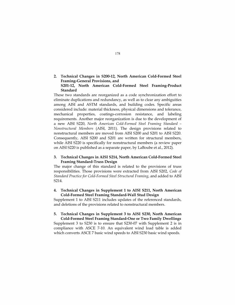
2. Technical Changes in S200-12, North American Cold-Formed Steel
Framing-General Provisions, and S201-12, North American Cold-Formed Steel Framing-Product Standard
These two standards are reorganized as a code synchronization effort to eliminate duplications and redundancy, as well as to clear any ambiguities among AISI and ASTM standards, and building codes. Specific areas considered include: material thickness, physical dimensions and tolerance, mechanical properties, coatings-corrosion resistance, and labeling requirements. Another major reorganization is due to the development of a new AISI S220, North American Cold-Formed Steel Framing Standard – Nonstructural Members (AISI, 2011). The design provisions related to nonstructural members are moved from AISI S200 and S201 to AISI S220. Consequently, AISI S200 and S201 are written for structural members, while AISI S220 is specifically for nonstructural members (a review paper on AISI S220 is published as a separate paper, by LaBoube et al., 2012).
3. Technical Changes in AISI S214, North American Cold-Formed Steel
Framing Standard-Truss Design The major change of this standard is related to the provisions of truss responsibilities. Those provisions were extracted from AISI S202, Code of Standard Practice for Cold-Formed Steel Structural Framing, and added to AISI S214. 4. Technical Changes in Supplement 1 to AISI S211, North American
Cold-Formed Steel Framing Standard-Wall Stud Design Supplement 1 to AISI S211 includes updates of the referenced standards, and deletions of the provisions related to nonstructural members. 5. Technical Changes in Supplement 3 to AISI S230, North American
Cold-Formed Steel Framing Standard-One or Two Family Dwellings Supplement 3 to S230 is to ensure that S230-07 with Supplement 2 is in compliance with ASCE 7-10. An equivalent wind load table is added which converts ASCE 7 basic wind speeds to AISI S230 basic wind speeds.
178

Table A1-3 Conversion of ASCE 7 Basic Wind Speeds to
AISI S230 Basic Wind Speeds (mph) 1 ASCE 7 Basic Wind Speed
110 115 126 139 152 164 177 190
AISI S230 Basic Wind Speed
85 90 100 110 120 130 140 150
For SI: 1 mph = 1.61 km/hr = 0.447 m/sec 1 ASCE 7 permits linear interpolation between the contours of the basic wind speed maps. Some connection requirements are revised accordingly. 6. New AISI S220, North American Cold-Formed Steel Framing
Standard-Nonstructural Members This standard addresses the design, installation, and testing analysis of cold-formed nonstructural members. The nonstructural member is defined as “A member in a steel-framed system that is not a part of the gravity load resisting system, lateral force resisting system or building envelope.” Examples of nonstructural members include those members in a steel framed system which is limited to a transverse (out-of-plane) load of not more than 10 lb/ft2 (0.48 kPa), a superimposed axial load, exclusive of sheathing materials, of not more than 100 lb/ft (1.46 kN/m), or a superimposed load of not more than 200 lbs (0.89 kN). The strength of the nonstructural members can be determined by either non-composite or composite design approach. The non-composite assembly design approach utilizes the design provisions of AISI S100 but with adjusted safety and resistance factors, N=0.9; and N=1.1; where , =Safety and resistance factors from relevant section of AISI S100; and N, N=Corresponding safety and resistance factors for nonstructural members. The non-composite assembly design approach can also be done via testing and with the test results evaluated in accordance with AISI S100 Chapter F but with a target reliability index, 0 = 1.6. For composite assembly design approach, it is generally accomplished by testing and with the test results evaluated in accordance with AISI S100 Chapter F. Detailed logistic of design provisions and design examples can be found from the paper (LaBoube et al, 2012).
179

References
American Institute of Steel Construction (2010), Specification for Structural Steel and Buildings.
American Iron and Steel Institute (2011), North American Cold-Formed Steel Framing Standard-Nonstructural Members. American National Standards Institute (2012), Essential Requirements: Due process requirements for American National Standards, Washington, DC 2012. Chen, H., R. L. Brockenbrough, R. Haws (2010), “An Overview of Recent Changes and Additions to AISI Standards,” Proceedings of the Twentieth International Specialty Conference on Cold-Formed Steel Structures, Missouri University of Science and Technology, Rolla, MO, November, 2010. LaBoube, A. R., H. Chen, and J. Larson (2012), New Standard AISI S220, North American Cold-Formed Steel Framing Standard-Nonstructural Members,” Proceedings of Twenty-First International Specialty Conference for Cold-Formed Steel Structures, Missouri University of Science and Technology, MO, November, 2012.
Zeinoddini, V and B. W. Schafer (2010), “Impact of Corner Radius on Cold-Formed Steel Member Strength,” Proceedings of the Twentieth International Specialty Conference on Cold-Formed Steel Structures, Missouri University of Science and Technology, Rolla, MO, November, 2010, 1-15.
180

Appendix A: AISI Standards Update Status Designation Title Status
AISI S100 North American Specification for the Design of Cold-Formed Steel Structural Members
Publish a new edition in 2012
AISI S110 Standard for Seismic Design of Cold-Formed Steel Structural Systems-Special Bolted Moment Frames
Reaffirm the 2007 edition
AISI S200 North American Cold-Formed Steel Framing – General Provisions
Publish a new edition in 2012
AISI S201 North American Cold-Formed Steel Framing – Product Data
Publish a new edition in 2012
AISI S202 North American Cold-Formed Steel Framing – Code of Standard Practice
Published in 2011
AISI S210 North American Cold-Formed Steel Framing – Floor and Roof System Design
Reaffirm the 2007 edition
AISI S211 North American Cold-Formed Steel Framing – Wall Stud Design
Reaffirm the 2007 edition
AISI S212 North American Cold-Formed Steel Framing – Header Design
Reaffirm the 2007 edition
AISI S213 North American Cold-Formed Steel Framing – Lateral Design
Reaffirm the 2007 edition
AISI S214 North American Cold-Formed Steel Framing – Truss Design
Publish a new edition in 2012
AISI S220 North American Cold-Formed Steel Framing – Nonstructural Members
Published in 2011
AISI S230 North American Cold-Formed Steel Framing – Prescriptive Method
Reaffirm the 2007 edition and Supplement 2
Publish Supplement 3 in 2012
181

(continue) AISI S901 Rotational-Lateral Stiffness Test Method for
Beam-to-Panel Assemblies 2008 Edition
AISI S902 Stub-Column Test Method for Effective Area of Cold-Formed Steel Columns
2008 Edition
AISI S903 Standard Methods for Determination of Uniform and Local Ductility
2008 Edition
AISI S904 Standard Test Methods for Determining the Tensile and Shear Strength of Screws
2008 Edition
AISI S905 Test Methods for Mechanically Fastened Cold-Formed Steel Connections
2008 Edition with Supplement 1
AISI S906 Standard Procedures for Panel and Anchor Structural Tests
2008 Edition
AISI S907 Test Standard for Cantilever Test Method for Cold-Formed Steel Diaphragm
2008 Edition
AISI S908 Base Test Method for Purlins Supporting a Standing Seam Roof System
2008 Edition
AISI S909 Standard Test Method for Determining the Web Crippling Strength of Cold-Formed Steel Beams
2008 Edition
AISI S910 Test Method for Distortional Buckling of Cold-Formed Steel Hat Shaped Compression Members
2008 Edition
AISI S911 Method for Flexural Testing Cold-Formed Steel Had Shaped Beams
2008 Edition
AISI S912 Test Procedure for Determining a Strength Value for a Roof Panel-to-Purlin-to-Anchorage Device Connection
2008 Edition
AISI S913 Test Standard for Hold-Downs Attached to Cold-Formed Steel Structural Framing
2008 Edition
AISI S914 Test Standard for Joist Connectors Attached to Cold-Formed Steel Structural Framing
2008 Edition
182