AISI Design Criteria for Bolted Connections
26
AISI DESIGN CRITERIA FOR BOLTED CONNECTIONS By Wei-Wen Yu l INTRODUCTION In the United States and some other countries, the bolted connect- ions used for cold-formed steel structures are designed in accordance with Section 4.5 of the AISI Specification (2). These design provisions were originally developed on the basis of the Cornell Tests (16,17) and updated in 1980 to reflect the results of additional research (4, 8, 9, 12, 18) and to provide a better coordination with the specifications of the Research Council on Structural Connections and the American Institute of Steel Construction (1, 14). The purpose of this paper is to summarize the changes of the design criteria and to document the research data used for the revision of Section 4.5 of the AISI Specification. Several design items are out- lined in this paper for future consideration. BASIS FOR THE REVISION OF THE DESIGN CRITERIA Section 4.5 of the AISI Specification is used to prevent the follow- ing four types of failure, which may occur in bolted connections: Type I Longitudinal shear failure of the sheet along two parallel lines (Fig. la) Type II Bearing failure or piling up of material in front of the bolt (Fig. lb) Type III - Tearing failure of the sheet in the net section (Fig. lc) Type IV Shearing failure of the bolt (Fig. ld) In the 1980 AISI Specification, three new subsections were added for scope, materials, and bolt installation. In addition, changes were made for the design provisions concerning minimum spacing and edge distance, allowable tensile stress for connected parts, allowable bearing stress between the connected part and bolt, and allowable shear stresses on bolts. lprofessor of Civil Engineering, University of Missouri-Rolla, Rolla Missouri. 675
Transcript of AISI Design Criteria for Bolted Connections

AISI DESIGN CRITERIA FOR BOLTED CONNECTIONS
By Wei-Wen Yul
INTRODUCTION
In the United States and some other countries, the bolted connections used for cold-formed steel structures are designed in accordance with Section 4.5 of the AISI Specification (2). These design provisions were originally developed on the basis of the Cornell Tests (16,17) and updated in 1980 to reflect the results of additional research (4, 8, 9, 12, 18) and to provide a better coordination with the specifications of the Research Council on Structural Connections and the American Institute of Steel Construction (1, 14).
The purpose of this paper is to summarize the changes of the design criteria and to document the research data used for the revision of Section 4.5 of the AISI Specification. Several design items are outlined in this paper for future consideration.
BASIS FOR THE REVISION OF THE DESIGN CRITERIA
Section 4.5 of the AISI Specification is used to prevent the following four types of failure, which may occur in bolted connections:
Type I Longitudinal shear failure of the sheet along two parallel lines (Fig. la)
Type II Bearing failure or piling up of material in front of the bolt (Fig. lb)
Type III - Tearing failure of the sheet in the net section (Fig. lc)
Type IV Shearing failure of the bolt (Fig. ld)
In the 1980 AISI Specification, three new subsections were added for scope, materials, and bolt installation. In addition, changes were made for the design provisions concerning minimum spacing and edge distance, allowable tensile stress for connected parts, allowable bearing stress between the connected part and bolt, and allowable shear stresses on bolts.
lprofessor of Civil Engineering, University of Missouri-Rolla, Rolla Missouri.
675

676 SIXTH SPECIALTY CONFERENCE
During the reV1S10n of the Specification, due consideration was given to the range of thicknesses of steel sheets, strip, flat bars, and plates, which are generally used for fabricating cold-formed steel structural members. Because previous studies and past practical experience have indicated that the structural behavior of bolted connections used for joining relatively thick cold-formed steel members is similar to that of connected hot-rolled shapes and built-up members, Section 4.5 is now applicable only to cold-formed steel members that are less than 3/16 in. (4.8 mm) in thickness. For materials not less than 3/16 in. (4.8 mm), the AISC design provisions (1) can be used for the design of bolted connections in cold-formed steel structures.
2. Materials
In previous editions of the AISI Specification, allowable shear stresses were given only for A307 and A325 bolts. Because the maximum thickness for cold-formed members has been increased from 1/2 in. (12.7 mm) to 1 in. (25.4 mm), other high-strength bolts, such as A354, A449, and A490 bolts, were added to the 1980 Specification for bolted connections.
In view of the fact that A325 and A490 bolts are available only for a diameter of 1/2 in. (12.7 mm) and larger, whenever smaller bolts (less than 1/2 in. (12.7 rom) in diameter) are required in a design, high-strength A449 and A354 Grade BD bolts can be used as equivalents of A325 and A490 bolts, respectively.
For other types of fasteners, which are not listed in this section, the allowable stresses should be determined by tests in accordance with the AISI Specification.
3. Bolt Installation
This new subsection was added to the 1980 specification to ensure that bolts are properly tightened according to acceptable practice followed by building constructors. Because the required pretension in bolts usually varies with the types of connected parts, fasteners, applied loads, and applications, no specific requirements are given in the 1980 specification for installation.
The method of installation and the effect of torques on the strength of bolted connections have been studied and reported in Refs. 10, 15 and 18. This background information is useful for developing future installation procedures.

BOLTED CONNECTIONS 677
4. Minimum Spacing and Edge Distance in Line of Stress
In previous editions of the AISI Specification, the mlnlmum end distance measured in the line of stress was determined by the following two requirements:
and e . mln
e . mln
l.5d (1)
p (2)
0.60F t Y
in which e. is the required mlnlmum end distance measured in the line of stress,mln in., d is the diameter of bolts, in., P is the allowable load transmitted by one bolt, kips, Fy is the yield point of connected parts, ksi, and t is the thickness of the thinnest connected part, in. Equation (2) was used to prevent the failure in longitudinal shearing of the connected part along two parallel lines in the direction of applied force. It was derived from the following equation with a safety factor of 2.3.
P u
e = ""1-.4""::"F=--t y
(3)
In the above equation, Pu is the failure load per bolt, kips (16, 17).
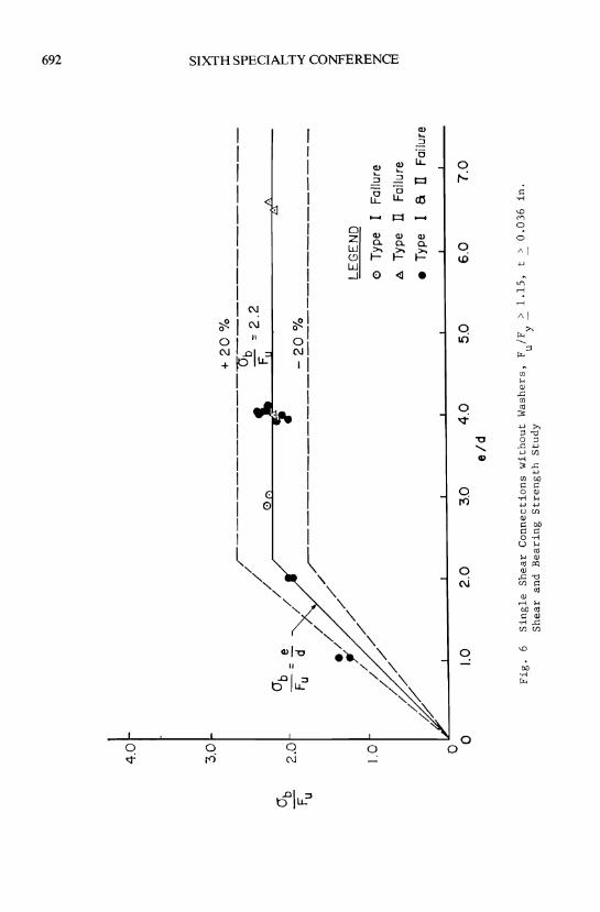
During recent years, additional studies have been made on the bearing strength of connections bolted with and without washers (4,5,6 8,9,12,18). The test data as shown in Figs. 2 to 7 indicate that for bolted connections having small e/d ratios, the bearing stress at failure can be predicted by Eq. (4):
(4)
in which 0b is the ultimate bearing stress between the bolt and connected part, ksi, and Fu is the tensile strength of the connected part, ksi. The proceeding equation is based on the results of bolted connection tests involved with the following parameters:
Diameter of bolt, d: 3/16 - 1 in. (4.8 - 25.4 mm) Thickness of connected part, t: 0.036 - 0.261 in. (0.9 - 6.6 mm) Edge distance, e: 0.375 - 2.50 in. (9.5 - 50.8 mm) Yield point of steel, Fy: 25.6 - 87.60 ksi (177 - 604 MPa) Tensile strength of steel, Fu: 41.15 - 91.30 ksi (284 - 630 MPa) e/d ratio: 0.833 - 3.37 d/t ratio: 2.61 - 20.83 Fu/Fy ratio: 1.00 - 1.63
The dimensions of the specimens and test results are given in Ref. 18.
678 SIXTH SPECIALTY CONFERENCE
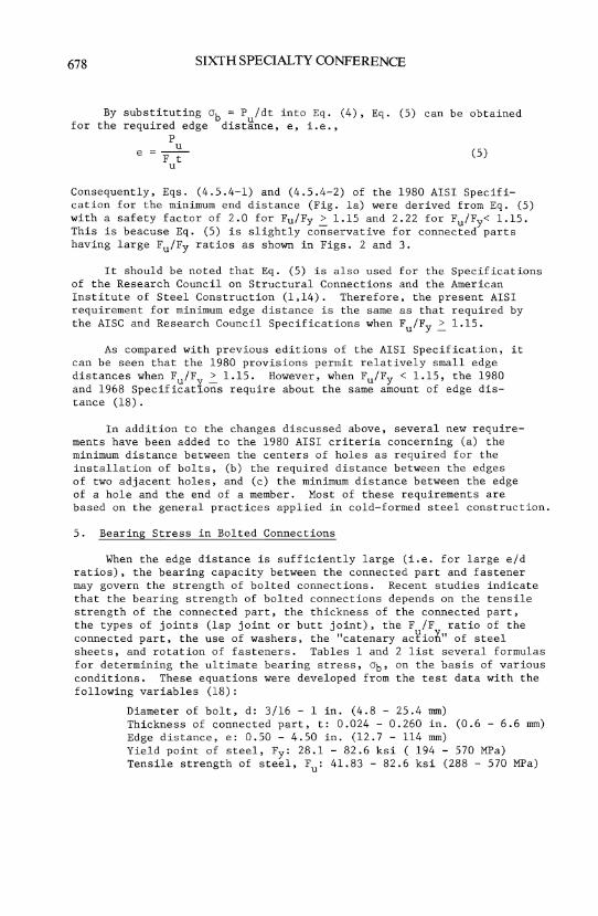
By substituting 0b = P /dt into Eq. (4), Eq. (S) can be obtained for the required edge dist~nce, e, i.e.,
P u
e = Ft (S) u
Consequently, Eqs. (4.S.4-l) and (4.S.4-2) of the 1980 AISI Specification for the minimum end distance (Fig. la) were derived from Eq. (S) with a safety factor of 2.0 for Fu/Fy ~ 1.lS and 2.22 for Fu/Fy< 1.lS. This is beacuse Eq. (S) is slightly conservative for connected parts having large Fu/Fy ratios as shown in Figs. 2 and 3.
It should be noted that Eq. (S) is also used for the Specifications of the Research Council on Structural Connections and the American Institute of Steel Construction (1,14). Therefore, the present AISI requirement for minimum edge distance is the same as that required by the AISC and Research Council Specifications when Fu/Fy ~ 1.lS.
As compared with previous editions of the AISI Specification, it can be seen that the 1980 provisions permit relatively small edge distances when Fu/Fy ~ 1.lS. However, when Fu/Fy < 1.lS, the 1980 and 1968 SpecificatLons require about the same amount of edge distance (18).
In addition to the changes discussed above, several new requirements have been added to the 1980 AISI criteria concerning (a) the minimum distance between the centers of holes as required for the installation of bolts, (b) the required distance between the edges of two adjacent holes, and (c) the minimum distance between the edge of a hole and the end of a member. Most of these requirements are based on the general practices applied in cold-formed steel construction.
S. Bearing Stress in Bolted Connections
When the edge distance is sufficiently large (i.e. for large e/d ratios), the bearing capacity between the connected part and fastener may govern the strength of bolted connections. Recent studies indicate that the bearing strength of bolted connections depends on the tensile strength of the connected part, the thickness of the connected part, the types of joints (lap joint or butt joint), the F /F ratio of the connected part, the use of washers, the "catenary aC¥ioft" of steel sheets, and rotation of fasteners. Tables 1 and 2 list several formulas for determining the ultimate bearing stress, 0b' on the basis of various conditions. These equations were developed from the test data with the following variables (18):
Diameter of bolt, d: 3/16 - 1 in. (4.8 - 2S.4 mm) Thickness of connected part, t: 0.024 - 0.260 in. (0.6 - 6.6 mm) Edge distance, e: O.SO - 4.S0 in. (12.7 - 114 mm) Yield point of steel, Fy: 28.1 - 82.6 ksi ( 194 - S70 MPa) Tensile strength of steel, Fu: 41.83 - 82.6 ksi (288 - S70 MPa)
BOLTED CONNECfIONS
eld ratio: 1.02 - 6.62 dlt ratio: 3.42 - 13.50 F IF ratio: 1.00 - 1.63
u y
The correlations between the test results and the equations for ab are shown in Figs. 2 to 8.
679
The allowable bearing stresses, F , specified in Tables 4.5.6 (A) and 4.5.6 (B) of the 1980 SpecificatioR were derived from the ultimate bearing stresses, ab' by using factors of safety ranging from 2.20 to 2.33. The actual factor of safety used for each case is also indicated in Tables 1 and 2.
It should be noted that the 1980 AISI provisions are limited only to certain thicknesses of materials because of a lack of test results for very thin sheets. For the thicknesses of materials not covered in Tables 4.5.6 (A) and 4.5.6 (B), the allowable bearing stress must be determined by the test data and a factor of safety of 2.22. A limited number of test data on very thin materials can be found in Ref. 8.
6. Tension Stress on Net Section
In the 1980 provisions, the design formula used for computing the allowable tension stress, Ft, on the net section of connected parts was changed as follows:
1. The provisions are applicable only to the thinnest connected part, which is less than 3/16 in. (4.8 mm) thick. For thick materials, the allowable tension stress is determined by using the AISC Specification (1).
2. The allowable tension stress for the net section of a connected member is determined by the tensile strength of the connected part (Fu) instead of the yield point of steel (F ).
3. Different Yformulas are used for bolted connections with and without washers.
4. The allowable tension stress for the net section of a connected member is based on the type of joint, either a single shear lap joint or a double shear butt joint.
For connections in which washers are placed under both the heads and nuts of the bolts, the equations for computing the allowable tension stress [Eqs. (4.5.5-1) and (4.5.5-2)J, were derived from the following formula for the ultimate tensile stress, anet , with the proper factors of safety.
anet = (1.0 - 0.9r + 3rd/s) Fu:: Fu (6)
In Eq. (6), a t is the ultimate tensile stress on the net section, ksi, s is then~pacing of bolts perpendicular to the line of stress, in., and r is a ratio of the force transmitted by the bolt or bolts at the section considered, divided by the tension force in the member at that section. The factors of safety used for deriving Eq. (4.5.5-1) of the

680 SIXTH SPECIALTY CONFERENCE
AISI Specification for double shear connections and Eq. (4.5.5-2) for single shear connections are 2.0 and 2.22, respectively.
The correlations between Eq. (6) and the test data are shown graphically in Figs. 9 to 11. The test specimens were involved with the following parameters (18):
Diameter of bolt, d: 1/4 - 1-1/8 in. (6.4 - 28.6 mm) Thickness of steel sheet, t: 0.0335 - 0.191 in. (0.9 - 4.9 mm) Width of steel sheet, s: 0.872 - 4.230 in. (22 - 107 mm) Yield point of steel, Fy: 26.00 - 99.40 ksi (179 - 685 MPa) Tensile strength of steel, Fu: 41.15 - 99.80 ksi (284 - 688 MPa) dis ratio: 0.063 - 0.50 d/t ratio: 3.40 - 21.13
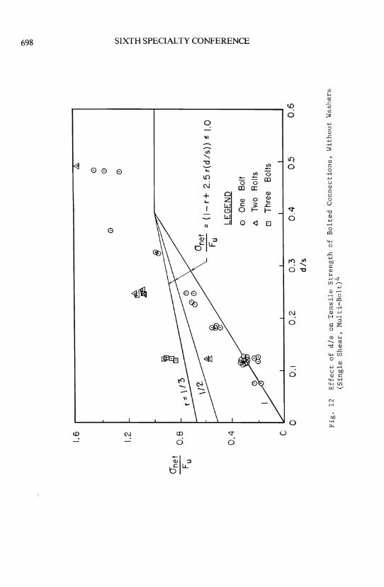
When washers are not used and when only one washer is used in bolted connections, the ultimate tensile stress on the net section, 0net' can be determined by using Eq. (7):
0net ~ (1.0 - r + 2.5r dis) Fu ~ Fu (7)
Equation (4.5.5-3) of the 1980 Specification was derived from the above formula by using a safety factor of 2.22. Figure 12 shows the correlation between Eq. (7) and the test data presented in Ref. 4.
7. Shear Stress on Bolts
In order to achieve a better coordination with the Specifications of the Research Council on Structural Connections and the American Institute of Steel Construction (1, 14), the allowable shear stresses for A325 bolts were increased by 36% in the 1980 design provisions. This increase is also justified by tests because the revised allowable stresses provide factors of safety ranging from 2.25 to 2.52 against shear failure of bolts (19). In addition, design values for A449, A490, and A354 Grade BD bolts were added for use of high strength bolts. The 1980 Specification permits the same allowable shear stresses for A307, A325, and A490 bolts as those specified in Refs. I and 14 for bearingtype connections.
It should be noted that in the 1980 Specification, small allowable shear stresses are used for A449 and A354 Grade BD bolts with threads in the shear planes as compared with those used for A325 and A490 bolts. This is based on the fact that the ratios of root-areal gross-area (~/~) for the 1/4 in. (6.4 mm) and 3/8 in. (9.5 mm) diameter bolts are smaller than those of the 1/2 in. (12.7 mm) diameter and larger bolts. For details, see Table 3. The reduced allowable shear stress for A449 and A354 Grade BD bolts are derived from the ~/~ ratios as follows:

BOLTED CONNECTIONS 681
For A449 bolts smaller than 1/2 in. (12.7 mm) in diameter,
F v
[ Avg.
21 (for A325 bolts) A vg.
~/~ for 1/4 in. and 3/8 in. bOltS]
~/~ for 1/2 in. and 1 in. bolts
21 0.585 = 18.33 ksi; 0.670
use F v
18 ksi (124 MPa)
For A354 Grade BD bolts smaller than 1/2 in. in diameter,
0.585 28 (for A490 bolts) x 0.671 = 24.45 ksi;
use F v
24 ksi (165 MPa)
FUTURE REVISION OF THE SPECIFICATION
Even though numerous changes were made in the 1980 Edition of the AISI Specification for the design of bolted connections, consideration should be given to the following items and others when the Specification is revised in the future.
Connection strength imparted by the inclination of fasteners, particularly when thin sheets are used in lap joints (3,10,15). Combined longitudinal shearing al~ng two parallel lines and tension in the traverse cross section of a steel sheet for bolt groups (11). Bearing capacity of very thin sheets when washers are not used (8). Bearing capacity affected by a selected deflection limit for connections (7). Structural strength of fasteners against uplift and pull-over. Allowable tension on bolts and allowable stress for combined shear and tension for bolts.
SUMMARY
The AISI design provisions for bolted connections were revised extensively in 1980. The major task of revising this portion of the Specification was carried out by a joint effort of the Task Group on Bolted Connections (1. W. Ife, Chairman) of the AISI Sheet Committees, Committee 27 (A. 1. Johnson, Chairman) of the Research Council on Structural Connections, and Subcommittee 3 (Wei-Wen Yu, Chairman) of the AISI Advisory Group on the Specification for the Design of ColdFormed Steel Structural Members (K. H. Klippstein, Chairman). This paper briefly reviews the reasoning behind and justification for the revised design provisions of the 1980 AISI Specification supported by the available research data.

682 SIXTH SPECIALTY CONFERENCE
APPENDIX I-REFERENCES
1. American Institute of Steel Construction, "Specification for the Design, Fabrication and Erection of Structural Steel for Buildings with Commentary," November 1, 1978.
2. American Iron and Steel Institute, "Specification for the Design of Cold-Formed Steel Structural Members," 1980 Edition.
3. Baehre, R., and Berggren, L., "Jointing of Thin-Walled Steel and Aluminum Structures," The National Swedish Institute for Building Research, 1971.
4. Chong, K. P., and Matlock, R.B., "Light Gage Steel Bolted Connections Without Washers," Journal of the Structural Division, ASCE Proceedings, Vol. 101, No. ST7, July 1975.
5. Dhalla, A.K., Errera, S.J., and Winter, G., "Connections in Thin Low-Ductility Steels," Journal of the Structural Division, ASCE Proceedings, Vol. 97, No. STlO, October 1971.
6. Fisher, J.W. and Struik, J.H.A., "Guide to Design Criteria for Bolted and Riveted Joints," John Wiley & Sons, 1974.
7. Frank, K.H. and Yura, J.A., "An Experimental Study of Bolted Shear Connections," The University of Texas at Austin, September 1981.
8. Gilchrist, R.T., and Chong, K. P., '''Thin Light-Gage Bolted Connections Without Washers," Journal of the Structural Division, ASCE Proceedings, Vol. 105, No. STl, January 1979.
9. Haussler, R.W., and Pabers, R.F., "Connection Strength in Thin Metal Roof Structures," Proceedings of the Second Specialty Conference on Cold-Formed Steel Structures, University of Missouri-Rolla, October 22-24, 1973.
10. Johnson, D.L., "Connections in Cold Formed Construction," Conference Proceedings on Cold-Formed Steel Structures, Canadian Society for Civil Engineering Ontario Region in cooperation with the Department of Civil Engineering, University of Windsor, April 1980.
11. Marsh, C., "Tear-Out Failure of Bolt Groups," Journal of the Structura:LPivision, ASCE Proceedings, Vol. 105, No. STIO, October 19~-
12. McKinney, W.M., Liu, V.A.S., and Yu, W.W., "Study of Cold-Formed Steel Structural Members Made of Thick Sheets and Plates," Final Report, University of Missouri-Rolla, -April 1975.
13. Popowich, D.W., "Tension Capacity of Bolted Connections in Light Gage Cold-Formed Steel," thesis presented to Cornell University in 1969, in partial fulfillment of the requirements for the degree of Master of Science.
BOLTED CONNECfIONS
14. Research Council on Structural Connections, "Specification for Structural Joints Using ASTM A325 or A490 Bolts," April 26, 1978.
683
15. Stark, J.W.B., and Toma, A.W., "Connections in Cold-Formed Sections and Steel Sheets," Proceedings of the Fourth International Specialty Conference on Cold-Formed Steel Structures, University of MissouriRolla, June 1-2, 1978.
16. Winter, G., "Tests on Bolted Connections in Light Gage Steel," Journal of the Structural Division, ASCE Proceedings, Vol. 82, No. ST2, March 1956.
17. Winter, G., "Light Gage Steel Connections With High-Strength, HighTorqued Bolts," Publication of the International Association for Bridge and Structural Engineering, Vol. 16, p. 513, 1956.
18. Yu, W.W., and Mosby, R.L., "Bolted Connection in Cold-Formed Steel Structures," University of Missouri-Rolla, January 1981.
19. American Iron and Steel Institute, "Commentary on the September 3, 1980 Edition of the Specification for the Design of Cold-Formed Steel Structural Members," to be published.

684 SIXTH SPECIALTY CONFERENCE
APPENDIX II - NOTATION
The following symbols are used in this paper:
~ gross area of bolt;
~ root area of bolt;
d diameter of bolt;
e end distance;
e . m1n
F P
Ft
F u
F v
F Y
P
P u
r
required minimum edge distance;
allowable bearing stress;
allowable tension stress on net section;
tensile strength of steel sheet or connected part;
allowable shear stress on bolt;
yield point of steel sheet or connected part;
allowable load transmitted by one bolt;
failure load per bolt;
ratio of the force transmitted by the bolt or bolts at the section considered, divided by the tension force in the member at that section;
s spacing of bolts perpendicular to the line of stress (In the case of a single bolt, s is the width of sheet.);
t thickness of steel sheet or connected part;
0b ultimate bearing stress at failure; and
0net ultimate tensile stress.

hickness of ~teel Sheet
( in.)
< 3/16 but > 0.024 -
Thickness of Steel Sheet
( in.)
< 3/16 but ~ 0.036
Note: 1 ~n.
BOLTED CONNECfIONS
TABLE 1
Bearing Strengths anu Allowable Bearing Stresses of Bolted Connections with Washers under Both Bolt Head and Nut
Type of F IF Ratio of . Ultimate Allowable Joint
u y Bearing Bearing
Steel Sheet Stress., ab Stress, F
(ksi) (ksi)
Inside sheet of double > 1.15 3.5 F 1.50 F shear - u U
connections < 1.15 3.0 F 1.35 F u u
Single shear connections > 1.15 3.0 F 1.35 F and inside - u u
sheets of < 1.15 3.0 F 1.35 F double shear
u u
connections
TABLE 2
Bearing Strengths and Allowable Bearing Stresses of Bolted Connections without Washers under Both Bolt Head and Nut
p
Type of F IF Ratio of Ultimate Allowable Joint u y
Bearing Steel Sheet Bearing Stress, ab
Stress, F (ksi)
p
(ksi)
Inside sheet of double > 1.15 3.0 F 1.35 shear F - u u connections
Single shear connections and outside
> 1.15 2.2 sheets of F 1.00 F - u u double shear connections
25.4 mm; 1 ks~ 6.9 MPa
685
Factor of
Safety
2.33
2.22
2.22
2.22
Factor of
Safety
2.22
2.20

\
686 SIXTH SPECIALTY CONFERENCE
TABLE 3
Gross-Areas and Root-Areas of Structural Bolts
Bolt Gross Area Root Area '\ Diameter ~2 '\ ~
(in. ) ( in. ) ( in. 2)
1/4 0.049 0.027 0.55
3/8 0.110 0.068 0.62
1/2 0.196 0.126 0.64
5/8 0.307 0.202 0.66
3/4 0.442 0.302 0.68
7/8 0.601 0.419 0.70
1 0.785 0.551 0.70
Note: The gross and root areas are based on the AISC Manual of Steel Construction, 8th Edition, p. 4-141.
1 in. = 25.4 mm; 1 in. 2 = 645 mm~

M
.\
5 \
('
~
~~----------------------~
(a)
Lo
ng
itu
din
al
shear
fail
ure
o
f sh
eet
(Ty
pe
I)
~\
S3 \
\1
~
(c)
Ten
sil
e fa
ilu
re
of
sh
eet
(Ty
pe
III)
• •
-\,
~I\\
\
~
(b)
Beari
ng
fa
ilu
re
of
sh
eet
(Ty
pe
II)
~I
~
I~
(d)
Sh
ear
fail
ure
o
f b
olt
(T
yp
e IV
)
Fig
. 1
Ty
pes
o
f F
ail
ure
o
f B
olt
ed
C
on
necti
on
s
t!i o t3 trJ o 8 ~ q (3 ~ 0'
1 0
0
-l

°b Fu
5.0
40
3,0
20
1.0 o
o o
r --
--
--
--
--
--
--
-~
3 ~ y~ --
/ 0
8 /
~.
----
2.-
30
Y' <
tl.@
F-·
, u
18 . /
8 ~
0 0
/'
/""
---0
---_
__
__
__
__
_ -=~~!o __
_
El
/ 8
/ 0
/ °b
/ FU
/
LEG
EN
D
/ ---
8/
/ [!
] Ty
pe
Failu
re
// //
0 T
ype
II Fa
ilure
.;; //
• T
ype
II
a I
Failu
re
~/
~'/
6.
Type
II
a
ill
Fai
lure
'?/
o 1.
0 2
.0
3.0
4.0
5
.0
6.0
7
.0
e Id
Fig
. 2
Sin
gle
S
hear
Co
nn
ecti
on
s w
ith
Wash
ers
, F
IF
> 1
.15
, S
hear
and
B
eari
ng
S
tren
gth
S
tud
y
u y
-
0\
00
0
0
[/J ~ ::t
[/J cil Q ~ ><
8 ~ 1il g

Gb Fu
6.0
5.0
4.0
3.0
2.0
1.0
G
G
/ . // G
b -!
. Fu
-
d ~//r
_/
/ //
/ //
// /
/.
/
;;//
~
/
o
o o
+2
0%
3.5
j -2
00 ;
' /~ _
__
_ -
0 _
__
_ 0 _
----
LE
GE
ND
G
Typ
e F
ailu
re
o
Typ
e n
Failu
re
• T
ype
n a
1
Fai
lure
IA
Typ
e II
a
m Fa
ilure
o ~V~ _
__
_ -L
__
__
__
-L~~~~~~ _
_ -L
__
__
__
~ _
__
__
_ ~ _
__
__
_ ~
o 1.
0 2
.0
3.0
4
.0
5.0
6
.0
7.0
e/d
Fig
. 3
Do
ub
le
Sh
ear
Co
nn
ecti
on
s w
ith
Was
her
s,
Fu
/Fy
>
1.1
5,
Sh
ear
and
B
eari
ng
S
tren
gth
Stu
dy
~ tl tI:I o 8 ~ ~ o ~ 0\
00
\0

(jb
Fu
5.0
4.0
3.0
2.0
1.0
/~ _
_ !
p __
.....
/
__
__
_ -P
__
+ 2
00 ;;
/ •
II>
0 ----'-
/ IT
b ~~
/ '"
F
· 3
.0
~ / 0
" /
0 i!:
.
//
r------
/ • //
__
_ . _
__
=2
0 %
0b
/
/ 0
---
__
e
/ /
Fu
-"dX
//
/
//
LEG
END
[!J
Type
I
Fai
lure
o
Typ
e IT
F
ailu
re
• T
ype
I a
IT
Fai
lure
o o
;:///
i!:.
Typ
e n
a il
l F
ailu
re
~/.'
/ r'/
o .~~--------~--------~--------~----------~--------~----------~--------~
o 1.
0 2
.0
3.0
4
.0
5.0
6
.0
7.0
e
/d
Fig
. 4
Sin
gle
S
hea
r C
on
nec
tio
ns
wit
h
Was
her
s,
Fu
/Fy
<
1.1
5,
Sh
ear
and
B
eari
ng
S
tren
gth
S
tud
y
'" ~ (/J ~ (/
J til o ~ ....:: 8 ~ ~ Q

O'b Fu
5.0
4.0
3.0
2.0
1.0
/ /
/
r-------2
20
%
/ ----
/ CJ
b /e
~ -=
30
/
/ ~
.
/
//
/
• 0
~____
-2
0 0
;' ///
----~-
CJb
=
Fu
/ /
//
~-'
all
/ /
/ //
~~//
~~/
V
LEG
END
G
Typ
e F
ailu
re
o T
ype
1 a
IT
Fai
lure
• T
ype
IT a
ill
Fai
lure
O~K------~--------~------~------~------~--------~----~
o
Fig
. 5
1.0
2.0
3.
0 4
.0
5.0
6
.0
7.0
e
/d
Do
ub
le
Sh
ear
Co
nn
ecti
on
s w
ith
Was
her
s,
F IF
<
1
.15
, S
hea
r an
d
Beari
ng
S
tren
gth
S
tud
y
u y
t::d o @
o 8 ~ Q
(3
~ 0\
'D
CJb Fu
4.0
3.0
2.0
1.0 O
iL"
o
CJb
e -=
(1
Fu
/
/~_________
+2
0%
//
--lJb
-------
/ /
00
.J.
F
=
2.2
-
/ •
I
~______
_ 2
0 0
1. //
-------~----
~
//
/ /
/ //
LEG
END
/ /
/ /-
,/,/
~
o T
ype
Fai
lure
A
Typ
e n
Fai
lure
• T
ype
I a
n F
ailu
re
1.0
2.0
3.0
4.0
5.0
6.0
7
.0
e/d
Fig
. 6
Sin
gle
S
hea
r C
on
nec
tio
ns
wit
ho
ut
Was
her
s,
F IF
>
1.1
5,
t >
0
.03
6
in.
Sh
ear
and
B
eari
ng
S
tren
gth
S
tud
y
U
y-
0..
'-
0
N
(/l
g :t
(/l
;:g o 5 8 ~ ~ Z @

°b Fu
4.0
3.0
2.0
1.0
o o
CYb
e -=
d"
Fu
/ _
__
__
__
__
__
4... _
__
__
__
__
_ + 2
0 %
/
0-------
/ §
0 b
!/
~
Fu =
2.2
/ §
0 0
~
/,;------
//
---
/ /
__
__
_ ..::
... 2
0 %
LEG
END
/
//
----
-
/./
//
/.'/
/
4//
/
o T
ype
Fai
lure
A
Type
U
F
ailu
re
• T
ype
I 8
IT
Fai
lure
1.0
2.0
3
.0
4.0
5
.0
6.0
7
.0
e /d
Fig
. 7
Sin
gle
S
hear
Co
nn
ecti
on
s w
ith
ou
t W
ash
ers,
F
IF
< 1
.15
, t
>
0.0
36
in
. S
hear
and
B
eari
ng
S
tren
gth
S
tud
y
u y
ttl o ti ~ 8 ~ q (5 ~ 0\
\0 ...,

°b Fu
4.0
3.0
+
20
%
~------------~--------
// r
= 2
.2
1.0
/ ~
0 /
. S
-2
00
1
/ ,,-_
__
__
__
__
__
_
/0
//
",//
--
LE
GE
Nn
---
/ /'"
0 Ty
pe n
Fai
lure
// /
O
"b
e F
ailu
re
occ
ure
d
~",
F
= d
In
th
e ou
tsid
e b
'/
u sh
eets
o
f th
e " ~
doub
le
shea
r r
conn
ectio
ns
2.0 °0
1.0
2.0
3.
0 4
.0
5.0
6.0
7
.0
e Id
Fig
. 8
Do
ub
le
Sh
ear
Co
nn
ecti
on
s w
ith
ou
t W
ash
ers
, F
IF
>
1.1
5,
t >
0
.03
6
in.
Beari
ng
S
tren
gth
S
tud
y
u y
-
0-
1.0 ~
C/l S
::c C/l til o ~ -< 8 ~ t:r1 ~ g

One
t Fu
1.6
1.2
0.8
0.4
/~
~
rq: '$'~.'-
~ ~(
'~----
-~~G~~
D t:.
. t:;
. /
,,"
~
/ t:;
. "
.. /8
:
,,/
/ .
/
If
/"
/ "
/ ,,
/ /
."
/ ,,-
/ '.
,../
/
/ ,/
o
/. /6
/."/
,... °n
et
= (0
.1 +
3 d
is)
~ Fu
t:;.
Type
II
I o
Type
1
8 II
I
[J
Type
II
8
ill
• Ty
pe
18
IT
8 ill
1.0
o L
I _
__
__
__
_ ~ _
__
__
__
_ ~ _
__
__
_ ~ _
__
__
__
_ _
L _
__
__
__
_ ~ _
__
__
_ ~
o 0.
1 0
.2
0.3
d
is
0.4
0
.5
0.6
Fig
. 9
Eff
ect
of
dis
o
n T
en
sile
S
tren
gth
of
Bo
lted
C
on
nec
tio
ns
wit
h W
ash
ers
(Do
ub
le
Sh
ear,
O
ne
Bo
lt)
ttl o S
o 8 ~ q 5 61 0">
\0
v.

°net
Fu
1.6
1.2
0.8
0.4
00
A
+2
0%
//~--------
----
---
A It
/.
.A/
1%
/A
G//
• •
A
A
/% ~
.,.,
r--
__
,:.EQ~ _
__
_
//.
~ ....
"""
A
-----
/ , .............
/
......
~/ ..
......
/
-6
~/..
<m
Y"
G
/./....
.. °n
et
~/
Tu""
= (0
.1 +
3
dis
) i!i
1.
0
0.1
0.2
0
.3
dis
0
.4
LEG
END
A
Typ
e ill
o T
ype
1 a
ill
G
Typ
e n
am
•
Typ
e 1
a n
a II
r
0.5
0
.6
Fig
. 10
E
ffect
of
dis
on
Ten
sile
S
tren
gth
of
Bo
lted
Co
nn
ecti
on
s w
ith
Was
hers
(S
ing
le S
hea
r,
One
B
olt
)
~ Ul ~ :I:
Ul ril o ~ -< I

1.6
1.2
t-O
()ne
t 0
.8 ~ ~../-=-_O;:t =
(1
-0.9
r+3
r(d
/s))
~ 1.
0 Fu
LEG
END
o
One
B
olt
0.4
t-
I/~
8.
Two
Bol
ts
o
Fig
. 11
o 0.
1 0
.2
0.3
d
is
El
Thr
ee
Bol
ts
0.4
0.
5
Eff
ect
of
dis
on
Ten
sile
S
tren
gth
of
Bo
lted
Co
nn
ecti
on
wit
h W
ash
ers
(Sin
gle
S
hear,
M
ult
i-B
olt
)13
ttl 0 ~ tTJ
10 8 ~ Q - 0 Z
1J
l
0.6
0\ ~
CJne
t Fu
1.6
0 0 0
0 1.
2 I-
~
0.8
~
°net
~
= (I
-r+
2.5
r(d
/s))
~ 1
.0
0.4
l-
/'
LEG
END
o O
ne
Bol
t
A
Two
Bol
ts
D
Thre
e B
olts
1
,/
C 0
0.1
0.2
0
.3
0.4
0.
5 0
.6
dIs
Fig
. 12
E
ffect
of
dis
on
Ten
sile
S
tren
gth
of
Bo
lted
Co
nn
ecti
on
s,
Wit
ho
ut
Was
hers
(S
ing
le S
hear,
M
ult
i-B
olt
)4
$ 00
C/l - ~ ::t
C/l til (') - ~ -< 8 ~ :;.d
tI1 g


![Bolted Connections[1]](https://static.fdocuments.in/doc/165x107/54e7f8c84a7959704f8b46b8/bolted-connections1.jpg)