
AISC-Connections in Steel
45
1 a teaching primer for colleges of architecture S T R U C T U R E O F T H E E V E R Y D A Y S T E E L American Institute of Steel Construction Title Slide a teaching primer for colleges of architecture STRUCTURE OF THE EVERYDAY : STEEL Structural Steel Connections
-
Upload
juan-carlos-torres-hernandez -
Category
Documents
-
view
155 -
download
26
Transcript of AISC-Connections in Steel

1
a te
achi
ng p
rimer
for c
olle
ges
of a
rchi
tect
ure
STR
UC
TU
RE
OF
TH
E E
VE
RYD
AY
S T
E E
L
American Institute of Steel Construction
Title Slide
a teaching primer for colleges of architecture
STRUCTURE OF THE EVERYDAY :
STEEL
Structural Steel Connections

2
a te
achi
ng p
rimer
for c
olle
ges
of a
rchi
tect
ure
STR
UC
TU
RE
OF
TH
E E
VE
RYD
AY
S T
E E
L
Project Director
Slide Design & Graphics
Modeling & Animations
Production Assistants
IT Coordination
Photography
Software
For additional information, please contact:
College of Architecture, UNC-Charlotte
PRODUCTION TEAM College of Architecture UNC - Charlotte
David Thaddeus, AIA, Associate Professor [email protected]
David Thaddeus, AIA
Deborah J. Arbes, RA
Jennifer AugustBrittany EakerKathy Phillips
Matt Parker
David Thaddeus, AIAJohn Cerny
PowerPointPhotoshopCinema 4D (Mac)
CREDITS
Joe CorsiDave Mayo
Structural Steel Connections |

3
a te
achi
ng p
rimer
for c
olle
ges
of a
rchi
tect
ure
STR
UC
TU
RE
OF
TH
E E
VE
RYD
AY
S T
E E
L
This project was made possible through funding from the American Institute of Steel Construction (AISC) with support from the College of Architecture at the University of North Carolina at Charlotte
Special thanks to the following people at AISC for their support and help over the duration of the project:Fromy Rosenberg,PE, Director, AISC University ProgramsMegan Maurer, Coordinator, AISC University Programs
The following people have my sincere gratitude for serving on the Focus Group and offering their comments and feedback in the development of this project :
Kurt Baumgartner, AIA, JIA, University of Illinois at Urbana Champaign Terri Meyer Boake, Associate Professor, University of WaterlooThomas Fowler, Associate Professor, California Polytechnic State UniversityHarry Kaufman, PE, NCARB, Professor, Southern Polytechnic State UniversityKemp Mooney, Kemp Mooney ArchitectsTim Mrozowski, AIA, Professor, Michigan State UniversityRyan Smith, Assistant Professor, University of Utah
The following AISC members have provided invaluable insight into the content of this teaching aid:
Ron Bruce, PE, President, Builders Steel Company, North Kansas City, MOLawrence Kruth, PE, Engineering & Safety Manager, Douglas Steel, Lansing, MIDavid McKenzie, PE, Vice President - Engineering, SP International, North Kansas City, MO
Acknowledgements
ACKNOWLEDGEMENTS Structural Steel Connections |

4
a te
achi
ng p
rimer
for c
olle
ges
of a
rchi
tect
ure
STR
UC
TU
RE
OF
TH
E E
VE
RYD
AY
S T
E E
L
The American Institute of Steel Construction (AISC) is a non-profit technical institute and trade association established in 1921 to serve the structural steel
design community and construction industry in the United States.
AISC is offering this teaching aid and learning tool for educational purposes only. The data and information in this presentation is not intended for use in the
physical construction of steel structures.
The information presented here is considered public information and as such may be distributed or copied. The use of appropriate credit to for images, byline,
animations, and content is requested.
We hope that you and your students will find this information useful.
Please contact Fromy Rosenberg ([email protected]) for further information on AISC or for feedback on this teaching / learning product.
Please contact David Thaddeus ([email protected]) for questions or comments on the content of this project.
Terms
TERMSStructural Steel Connections |

5
a te
achi
ng p
rimer
for c
olle
ges
of a
rchi
tect
ure
STR
UC
TU
RE
OF
TH
E E
VE
RYD
AY
S T
E E
L
Module III Contents :
Connections
Structural Steel Connections
Steel to Steel Connections
Overview
Bolted Connections
Welded Connections
Comparison Shear Connections Moment Connections Column Splices Additional Animations
Roller Connection
Curtain Wall to Steel Frame
CONTENTS Structural Steel Connections |
Contents

6
a te
achi
ng p
rimer
for c
olle
ges
of a
rchi
tect
ure
STR
UC
TU
RE
OF
TH
E E
VE
RYD
AY
S T
E E
L
Steel Connections | Overview
Connections are the glue that holds a steel structure together.
Historically, most major structural failures have been due to some form of connection failure.
Connections depend on:
Type of loading Strength and stiffness Economy Difficulty or ease of erection
OVERVIEWStructural Steel Connections |
7
a te
achi
ng p
rimer
for c
olle
ges
of a
rchi
tect
ure
STR
UC
TU
RE
OF
TH
E E
VE
RYD
AY
S T
E E
L
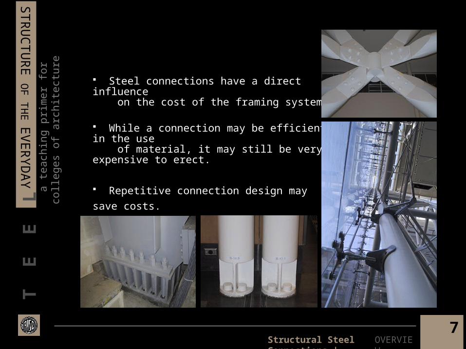
Steel connections have a direct influence on the cost of the framing system.
While a connection may be efficient in the use of material, it may still be very expensive to erect.
Repetitive connection design may save costs.
OVERVIEWStructural Steel Connections |

8
a te
achi
ng p
rimer
for c
olle
ges
of a
rchi
tect
ure
STR
UC
TU
RE
OF
TH
E E
VE
RYD
AY
S T
E E
L Most connections have the connecting material (plates,angles, …) attached to one member in the fabrication shop and to the other members in the field.
It is a common practice to weld shop attachments and to bolt field attachments.
If the supporting girder and a supported beam have the same depth, the supported beam must be double coped.
End-plate connections are always shop welded.
OVERVIEWStructural Steel Connections |

9
a te
achi
ng p
rimer
for c
olle
ges
of a
rchi
tect
ure
STR
UC
TU
RE
OF
TH
E E
VE
RYD
AY
S T
E E
L
Bolting is the preferred method of connecting members on the site. Staggered bolt layout allows easier access for tightening with a pneumatic wrench when a connection is all bolted .
High strength bolts may be snug-tightened or slip-critical.
Snug-tightened connections are referred to as bearing connections
Bolts in a slip-critical connection act like clamps holding the plies of the material together.
Steel Connections | Bolted Connections
BOLTED CONNECTIONSStructural Steel Connections |

10
a te
achi
ng p
rimer
for c
olle
ges
of a
rchi
tect
ure
STR
UC
TU
RE
OF
TH
E E
VE
RYD
AY
S T
E E
L
Bearing type connections may have threads included ( Type N ) or excluded ( Type X ) from the shear plane(s).
Including the threads in the shear plane reduces the strength of the connection by approximately 25%.
Loading along the length of the bolt puts the bolt in axial tension.
If tension failure occurs, it usually takes place at the threaded section.
Cy Twombly Gallery. Houston, TexasRenzo Piano
Milwaukee Art Museum. Milwaukee, WisconsinSantiago Calatrava
BOLTED CONNECTIONSStructural Steel Connections |

11
a te
achi
ng p
rimer
for c
olle
ges
of a
rchi
tect
ure
STR
UC
TU
RE
OF
TH
E E
VE
RYD
AY
S T
E E
L
Three types of high strength bolts A325, A490 (Hexagonal Head Bolts), and F1852 (Button Head Bolt)
A325 may be galvanized A490 bolts must not be galvanized F1852 bolts are mechanically galvanized
High strength bolts are most commonly available in 5/8” – 1 ½” diameters
Bolting requires punching or drilling of holes
Holes may be standard size holes, oversize holes, short slotted holes, long slotted holes
Oversize holes allow for tolerancein assembling the frame
Slotted holes allow for thermal expansion / contraction
BOLTED CONNECTIONSStructural Steel Connections |

12
a te
achi
ng p
rimer
for c
olle
ges
of a
rchi
tect
ure
STR
UC
TU
RE
OF
TH
E E
VE
RYD
AY
S T
E E
L
Due to high costs of labor, extensive field -welding is the most expensive component in a steel frame.
Welding should be performed on bare metal.
Shop welding is preferred over field welding.
The weld material should have a higher strength than the pieces being connected.
BCE Place GalleriaToronto . CanadaSantiago Calatrava10
De Menil Collection MuseumHouston . Texas
Renzo Piano
Steel Connections | Welded Connections
WELDED CONNECTIONS
Structural Steel Connections |
13
a te
achi
ng p
rimer
for c
olle
ges
of a
rchi
tect
ure
STR
UC
TU
RE
OF
TH
E E
VE
RYD
AY
S T
E E
L
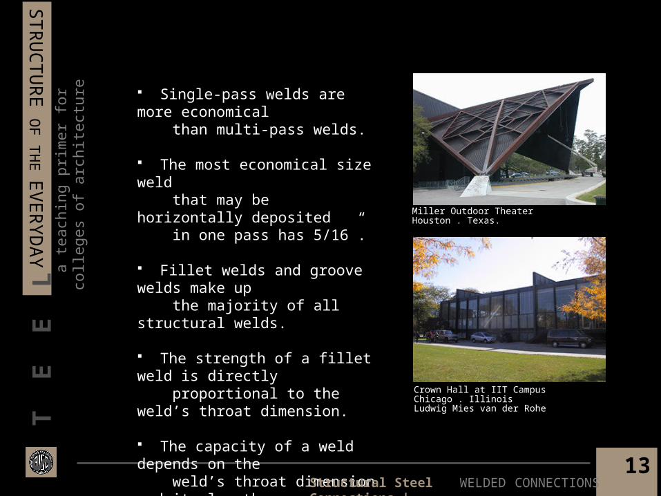
Single-pass welds are more economical than multi-pass welds.
The most economical size weld that may be horizontally deposited in one pass has 5/16”.
Fillet welds and groove welds make up the majority of all structural welds.
The strength of a fillet weld is directly proportional to the weld’s throat dimension.
The capacity of a weld depends on the weld’s throat dimension and its length
Miller Outdoor TheaterHouston . Texas.
Crown Hall at IIT CampusChicago . IllinoisLudwig Mies van der Rohe
WELDED CONNECTIONSStructural Steel Connections |

14
a te
achi
ng p
rimer
for c
olle
ges
of a
rchi
tect
ure
STR
UC
TU
RE
OF
TH
E E
VE
RYD
AY
S T
E E
L
Shear connections are the most prevalent type of connections in a steel frame building.
Shear connections are called simple connections – Since they are assumed not to transfer bending moment, thus allowing end rotation of the member.
Shear connections may be made to the web of the supported member while the flanges remain unconnected.
Cantilevered Beam with Shear splice Shear Connections transfer load from beam web to column flange. No moment transfer occurs since the flanges are free to rotate
Steel Connections | Shear Connections
SHEAR CONNECTIONSStructural Steel Connections |

15
a te
achi
ng p
rimer
for c
olle
ges
of a
rchi
tect
ure
STR
UC
TU
RE
OF
TH
E E
VE
RYD
AY
S T
E E
L
The weld material should have a higher strength than the pieces being connected. Seat or hanger connections are the only type of shear connections that connect to the flange of the supported beam.
Angles for shear connections may be attached to supporting members by bolting or welding.
Although single plate connections, are the most economical, they must always be evaluated for eccentricity.
Single angle connections maintain end-rotation for flexible connections.
Single angle connections tend to have lower load capacities than double-angle connections.
The Corning Museum of GlassCorning . New YorkSmith - Miller + Hawkinson
SHEAR CONNECTIONSStructural Steel Connections |

16
a te
achi
ng p
rimer
for c
olle
ges
of a
rchi
tect
ure
STR
UC
TU
RE
OF
TH
E E
VE
RYD
AY
S T
E E
L
Moment connections are also called rigid connections.
Moment connections carry a portion or the full moment capacity of the supported member thus preventing any end-rotation of the member.
Moment connections are typically designed to also carry the shear component of the load.
The Royal Ontario MuseumToronto . CanadaDaniel Libeskind
Steel Connections | Moment Connections
MOMENT CONNECTIONSStructural Steel Connections |
17
a te
achi
ng p
rimer
for c
olle
ges
of a
rchi
tect
ure
STR
UC
TU
RE
OF
TH
E E
VE
RYD
AY
S T
E E
L
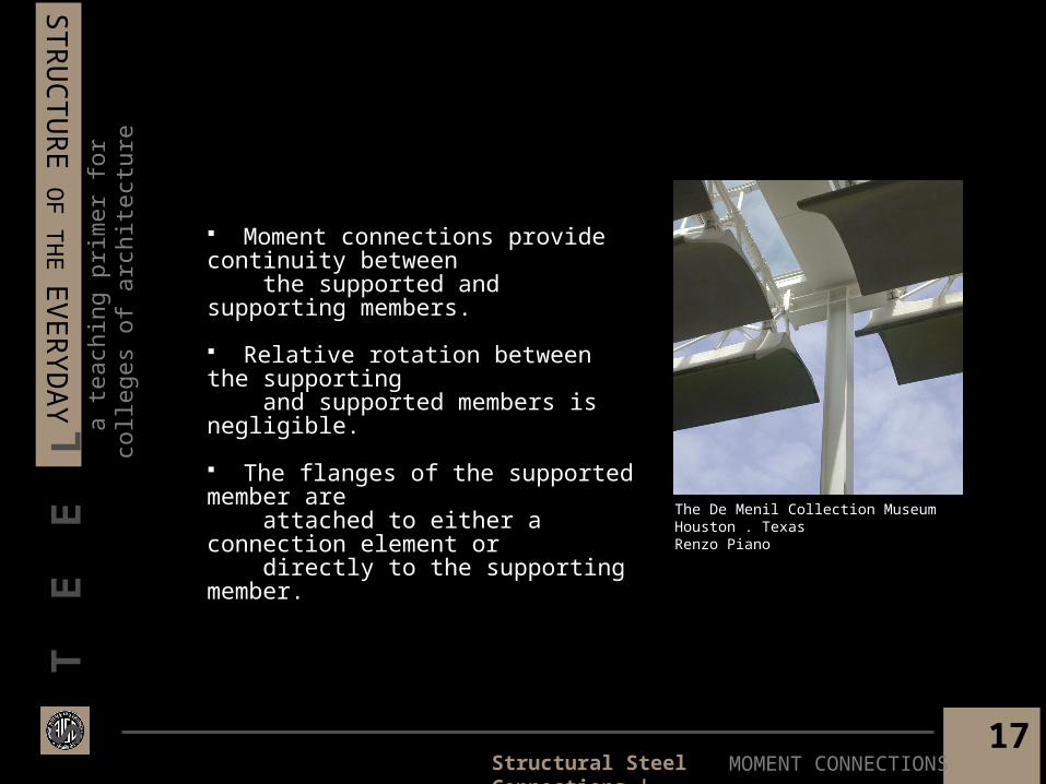
Moment connections provide continuity between the supported and supporting members.
Relative rotation between the supporting and supported members is negligible.
The flanges of the supported member are attached to either a connection element or directly to the supporting member.
The De Menil Collection MuseumHouston . TexasRenzo Piano
MOMENT CONNECTIONSStructural Steel Connections |

18
a te
achi
ng p
rimer
for c
olle
ges
of a
rchi
tect
ure
STR
UC
TU
RE
OF
TH
E E
VE
RYD
AY
S T
E E
L
WELDING vs. BOLTING
Steel Connections | Welding vs. Bolting
Structural Steel Connections |
Advantages:
• Eliminates need for punching or drilling.• Simplifies complicated joints.
Disadvantages:
• Greater level of skill required for welding than bolting• More expensive than bolting.• Weld inspection is required and is expensive.
Advantages:
• Easy method of connecting members on the site.• Field-bolting is cheaper than field-welding.
Disadvantages:
• Requires drilling or punching through all plies.
BOLTINGWELDING

19
a te
achi
ng p
rimer
for c
olle
ges
of a
rchi
tect
ure
STR
UC
TU
RE
OF
TH
E E
VE
RYD
AY
S T
E E
LShop-Bolted Double Angle | Field-Bolted Beam to Girder or Column
Double angles are shop-bolted to the web of the beam.
If the beam and girder have the same depth, then both flanges of the beam are coped to meet flush with the top flange of the girder.
The double angles are then field-bolted to the web of the girder.
The holes on the beam and the girder may be offset with respect to each other for ease of fastening.
Some rotation is possible in the gap between the beam flanges and the column web. This happens by the yielding of the connection material (the outstanding angle leg)
This is a shear connection since the double Angles are fastened to the web, and transfer the load in shear.
The bolts on the beam web are in double shear. Those on the girder web are in single shear.
SHEAR 1Structural Steel Connections |

20
a te
achi
ng p
rimer
for c
olle
ges
of a
rchi
tect
ure
STR
UC
TU
RE
OF
TH
E E
VE
RYD
AY
S T
E E
LShop-Bolted Double Angle | Field-Bolted Beam to Girder or Column
SHEAR 1Structural Steel Connections |

21
a te
achi
ng p
rimer
for c
olle
ges
of a
rchi
tect
ure
STR
UC
TU
RE
OF
TH
E E
VE
RYD
AY
S T
E E
L Double angles are shop-welded to the web of the beam.
If the beam and girder have different depth, the top flange of the beam is coped to meet flush with the top flange of the girder.
The double angles are then field-bolted to the web of the girder.
Some rotation is possible in the gap between the beam flanges and the column web. This happens by the yielding of the connection material (the outstanding angle leg).
This is a shear connection since the double angles are fastened to the web, and transfer the load in shear.
The bolts on the girder web are in single shear.
SHEAR 2
Shop-Welded Double Angle | Field-Bolted Beam to Girder or Column
Structural Steel Connections |

22
a te
achi
ng p
rimer
for c
olle
ges
of a
rchi
tect
ure
STR
UC
TU
RE
OF
TH
E E
VE
RYD
AY
S T
E E
L
SHEAR 2
Shop-Welded Double Angle | Field-Bolted Beam to Girder
Structural Steel Connections |

23
a te
achi
ng p
rimer
for c
olle
ges
of a
rchi
tect
ure
STR
UC
TU
RE
OF
TH
E E
VE
RYD
AY
S T
E E
L
Double angles are shop-welded to the web of the beam.
If the beam flanges are too wide to fit in between the column flanges, the beam flanges will be coped.
Some rotation is possible in the gap between the beam flanges and the column web. This happens by the yielding of the connection material (the outstanding angle leg)
This is a shear connection since the double angles are fastened to the webs of the beam and column.
The vertical segment of the weld transfers the load from the beam web to the column web.
Welding all around the outstanding leg will inhibit the flexibility of the connection.
The weld at the top is limited to a weld-return.
The weld at the bottom is optional.
SHEAR 3
Shop-Welded Double Angle | Field-Welded Beam to Column Web
Structural Steel Connections |

24
a te
achi
ng p
rimer
for c
olle
ges
of a
rchi
tect
ure
STR
UC
TU
RE
OF
TH
E E
VE
RYD
AY
S T
E E
L
SHEAR 3
Shop-Welded Double Angle | Field-Welded Beam to Column Web
Structural Steel Connections |

25
a te
achi
ng p
rimer
for c
olle
ges
of a
rchi
tect
ure
STR
UC
TU
RE
OF
TH
E E
VE
RYD
AY
S T
E E
L
End plate is shop-welded to the web of the beam.
Holes in the end plate are drilled in the shop.
Some rotation is possible in the gap between the beam flanges and the column web. This happens by the yielding of the connection material (the outstanding angle leg) The end plate is then field-bolted to the web of the girder.
This is a shear connection as the end plate is fastened to the web of the girder (beam flanges are not secured against rotation)
The bolts attaching the end plate to the girder web are in single shear.
SHEAR 4
Shop-Welded Double Angle | Field-Welded Beam to Column Web
Structural Steel Connections |

26
a te
achi
ng p
rimer
for c
olle
ges
of a
rchi
tect
ure
STR
UC
TU
RE
OF
TH
E E
VE
RYD
AY
S T
E E
LShop-Welded Double Angle | Field-Bolted Column Web
SHEAR 4Structural Steel Connections |

27
a te
achi
ng p
rimer
for c
olle
ges
of a
rchi
tect
ure
STR
UC
TU
RE
OF
TH
E E
VE
RYD
AY
S T
E E
L
The angles are pre-drilled or punched in the shop before they are welded to the flanges of the girder.
The bottom angle is called the seat.
The seat is where the girder transfers its load to the column in bearing.
The top angle provides stability to the girder.
The seat angle is larger and thicker since it transfers the load from the girder to the column.
Unlike others, this shear connection is not made to the web.
The bolts attaching the seat angle to the column flange are in single shear.
SHEAR 5
Shop-Welded Seat (Unstiffened) | Field-Bolted Seat to Column Flange
Structural Steel Connections |

28
a te
achi
ng p
rimer
for c
olle
ges
of a
rchi
tect
ure
STR
UC
TU
RE
OF
TH
E E
VE
RYD
AY
S T
E E
LShop-Welded Seat (Unstiffened) | Field-Bolted Seat to Column Flange
SHEAR 5Structural Steel Connections |

29
a te
achi
ng p
rimer
for c
olle
ges
of a
rchi
tect
ure
STR
UC
TU
RE
OF
TH
E E
VE
RYD
AY
S T
E E
L
The single plate is pre-drilled or punched and then shop-welded to the web of the girder.
The beam may be swung into place instead of lowered into place.
The top flange of the beam is coped to match the girder elevation.
This is a shear connection since the single plate is fastened to the web of the beam.
The bolts shown are in single shear.
This connection can transfer a small amount of moment to the supporting member
SHEAR 6
Shop-Welded Single Plate | Field-Bolted Plate to Beam or Column
Structural Steel Connections |

30
a te
achi
ng p
rimer
for c
olle
ges
of a
rchi
tect
ure
STR
UC
TU
RE
OF
TH
E E
VE
RYD
AY
S T
E E
LShop-Welded Single Plate | Field-Bolted Plate to Beam Web
Structural Steel Connections | SHEAR 6

31
a te
achi
ng p
rimer
for c
olle
ges
of a
rchi
tect
ure
STR
UC
TU
RE
OF
TH
E E
VE
RYD
AY
S T
E E
L
The top and bottom flange plates are pre- drilled and then shop-welded to the column.
The single plate is shop-bolted to the web of the girder.
The top and bottom flange plates are field-bolted to the girder flanges.
The single plate is field-welded to the column web.
The flange plates are cut to fill the space between the column flanges.
The corners of the flange plates are clipped to eliminate the development of stress concentrations at the re-entrant (back) corners.
These corners are left open and are not welded.
The single plate on the girder web transfers shear to the column.
The flange plates prevent rotation and thus the transfer of moment forces to the column
Allowance for shims must be made. Mill tolerance on beam depth needs to be accommodated
The Corning Museum of GlassCorning . New York
Smith - Miller + Hawkinson
MOMENT 1
Shop-Welded Flange Plates | Field-Bolted Girder to Column
Structural Steel Connections |

32
a te
achi
ng p
rimer
for c
olle
ges
of a
rchi
tect
ure
STR
UC
TU
RE
OF
TH
E E
VE
RYD
AY
S T
E E
LShop-Welded Flange Plates | Field-Bolted Girder to Column
MOMENT 1Structural Steel Connections |

33
a te
achi
ng p
rimer
for c
olle
ges
of a
rchi
tect
ure
STR
UC
TU
RE
OF
TH
E E
VE
RYD
AY
S T
E E
L The top and bottom flanges are pre-drilled and then shop-welded to the column.
The single plate is shop-bolted to the web of the girder.
The top and bottom flange plates are field-welded to the girder flanges.
The single plate is field-welded to the column web.
The flange plates are cut to fill the space between the column flanges.
The corners of the flange plates are clipped to eliminate the development of stress concentrations at the re-entrant (back) corners.
These corners are left open and are not welded.
The single plate on the girder web transfers shear to the column
The flange plates prevent rotation and thus the transfer of moment forces to the column, which makes this a moment connection
Allowance for shims must be made. Mill tolerance on beam depth needs to be accommodated
MOMENT 2
Shop-Welded Flange Plates | Field-Bolted Girder to Column
Structural Steel Connections |

34
a te
achi
ng p
rimer
for c
olle
ges
of a
rchi
tect
ure
STR
UC
TU
RE
OF
TH
E E
VE
RYD
AY
S T
E E
LShop-Welded Flange Plates | Field-Bolted Girder to Column
MOMENT 2Structural Steel Connections |

35
a te
achi
ng p
rimer
for c
olle
ges
of a
rchi
tect
ure
STR
UC
TU
RE
OF
TH
E E
VE
RYD
AY
S T
E E
L
The end plate is pre-drilled and shop-welded to the end of the girder.
The corresponding holes in the column flange are pre-drilled.
The two transverse stiffener plates are shop- welded to secure the column flanges against the load transferred from the girder flanges.
Extended end-plate connections require tight fabrication and erection tolerances.
Extended end plate prevents rotation and thus transfers moment forces to the column, which makes this a moment connection.
MOMENT 3
Shop-Welded End Plate | Field-Bolted Girder to Column
Structural Steel Connections |

36
a te
achi
ng p
rimer
for c
olle
ges
of a
rchi
tect
ure
STR
UC
TU
RE
OF
TH
E E
VE
RYD
AY
S T
E E
LShop-Welded Plate | Field-Bolted Girder to Column
MOMENT 3Structural Steel Connections |

37
a te
achi
ng p
rimer
for c
olle
ges
of a
rchi
tect
ure
STR
UC
TU
RE
OF
TH
E E
VE
RYD
AY
S T
E E
L
All holes in this connection are pre-drilled in the shop.
The web and flanges of each girder are pre-drilled.
(2) Shear plates are field-bolted in each side of the webs. The plates that attach the (2) webs to each other are responsible for transferring shear. Pre-drilled flange plates are field-bolted to the top and bottom flanges. The flange plates are responsible for transferring bending moments across the connection.
The bolts fastening the web plates are in double shear.
The flange plates prohibit any rotation and so this is a moment connection.
The Royal Ontario MuseumToronto . CanadaDaniel Libeskind
MOMENT 4
Field-Bolted Moment Splice | Girder to Girder or Column Connection
Structural Steel Connections |

38
a te
achi
ng p
rimer
for c
olle
ges
of a
rchi
tect
ure
STR
UC
TU
RE
OF
TH
E E
VE
RYD
AY
S T
E E
L
MOMENT 4
Field-Bolted Moment Splice | Girder to Girder or Column Connection
Structural Steel Connections |

39
a te
achi
ng p
rimer
for c
olle
ges
of a
rchi
tect
ure
STR
UC
TU
RE
OF
TH
E E
VE
RYD
AY
S T
E E
L
The plates are pre-punched and then shop-welded to the lower (larger) column.
The flange splice plates are field-bolted together.
If the two columns have the same depth, but different flange thickness, then a filler plate or shim is used to make up the difference in thickness.
COLUMN SPLICE 1
Shop-Welded or Shop Bolted Splice | Connecting Two Different Columns
Structural Steel Connections |

40
a te
achi
ng p
rimer
for c
olle
ges
of a
rchi
tect
ure
STR
UC
TU
RE
OF
TH
E E
VE
RYD
AY
S T
E E
L
COLUMN SPLICE 1
Shop-Welded or Shop Bolted Splice | Connecting Two Different Size Columns
Structural Steel Connections |

41
a te
achi
ng p
rimer
for c
olle
ges
of a
rchi
tect
ure
STR
UC
TU
RE
OF
TH
E E
VE
RYD
AY
S T
E E
L
A temporary plate or erection aid is either welded or bolted to the web and / or flange of the lower (larger) column in the shop.
Flange plates may also be required for stability of the column during erection.
This plate helps align the upper and lower columns.
The upper and lower columns may be of different sizes.
The flanges and webs of the two columns are field- welded to each other.
This type of weld is called a groove weld.
Steel Columns are most economical when they extend over 2 or more stories
Groove welds
Field - Welded Column Splice
COLUMN SPLICE 2Structural Steel Connections |

42
a te
achi
ng p
rimer
for c
olle
ges
of a
rchi
tect
ure
STR
UC
TU
RE
OF
TH
E E
VE
RYD
AY
S T
E E
LShop-Welded, Field - Bolted Column Splice
COLUMN SLPICE 2Structural Steel Connections |

43
a te
achi
ng p
rimer
for c
olle
ges
of a
rchi
tect
ure
STR
UC
TU
RE
OF
TH
E E
VE
RYD
AY
S T
E E
L
Rock & Roll ConnectionStructural Steel Connections |
Thermal Expansion and Contraction for a Highway Girder on a Roller Connection
44
a te
achi
ng p
rimer
for c
olle
ges
of a
rchi
tect
ure
STR
UC
TU
RE
OF
TH
E E
VE
RYD
AY
S T
E E
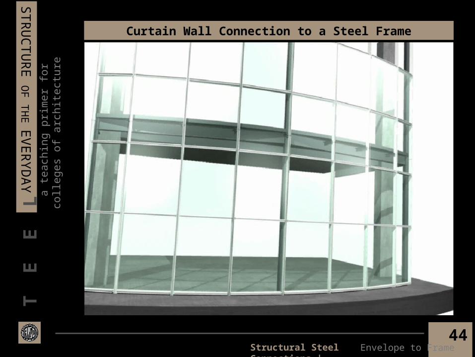
LCurtain Wall Connection to a Steel Frame
Envelope to FrameStructural Steel Connections |

45
a te
achi
ng p
rimer
for c
olle
ges
of a
rchi
tect
ure
STR
UC
TU
RE
OF
TH
E E
VE
RYD
AY
S T
E E
L
the end
The American Institute of Steel ConstructionStructural Steel Connections |


![[AISC] Detailing for Steel Construction (Bookos.org)](https://static.fdocuments.in/doc/165x107/55cf91a0550346f57b8f0f85/aisc-detailing-for-steel-construction-bookosorg.jpg)


