AIRSYS Wall Packaged Units - AIRSYS North...
29
AIRSYS Wall Packaged Units Troubleshooting Guide
Transcript of AIRSYS Wall Packaged Units - AIRSYS North...

AIRSYS Wall Packaged Units Troubleshooting Guide
TABLE OF CONTENTS Safety Instruction .......................................................................................................................................... 1
1 Model Identification ............................................................................................................................. 2
2 Controller Software Identification ........................................................................................................ 2
3 Controller Menus .................................................................................................................................. 3
3.1 Menu Structure .............................................................................................................................. 3
3.2 Sub Menus ...................................................................................................................................... 4
4 Alarms Troubleshooting ........................................................................................................................ 5
4.1 Low Pressure Alarm (A02/A04) ...................................................................................................... 5
4.2 High Pressure Alarm (A03/A06)...................................................................................................... 7
4.3 Smoke/Fire Alarm (A05) ................................................................................................................. 9
4.4 High Temp Alarm (A07) ................................................................................................................ 10
4.5 Low Temp Alarm (A08) ................................................................................................................. 12
4.6 DC Failover (A09) .......................................................................................................................... 14
4.7 Evaporator Fan Overload/AC Loss (A10/A11) .............................................................................. 15
4.8 Dirty Air Filter (A15/A16) .............................................................................................................. 17
4.9 pLAN alarm (A17) ......................................................................................................................... 18
4.10 Clock Card Alarm (A18) ............................................................................................................. 19
4.11 Humidity Sensor Alarm (A19) ................................................................................................... 19
4.12 Temp Sensor Alarm (A20/A21/A22/A26/A27) ......................................................................... 20
4.13 Two Compressor Run (A23) ...................................................................................................... 20
4.14 Damper Alarm (A24/A25) ......................................................................................................... 21
4.15 Generator Run (A28) ................................................................................................................. 23
4.16 DC Fan Air Flow Alarm (A29/A30) ............................................................................................. 24
4.17 AC Loss for DC Fan Systems (A31/A32)..................................................................................... 25
5 Symptoms with No Alarms .................................................................................................................. 27
5.1 System function ............................................................................................................................ 27
5.2 No Controller Display ................................................................................................................... 27

SAFETY INSTRUCTION Default Menu Structure
Pg. 1 Rev 1.1
SAFETY INSTRUCTION
IMPORTANT
All service work must be done by qualified professional technicians. Always wear protective gear and
comply with all general and local safety standards and codes. Adhere to all warnings and safety
instructions on the units and in this manual. AIRSYS and its U.S. distributor, Tempest Telecom Solutions,
shall not be held liable for any damage to persons or property due to improper operation or servicing of
this equipment.
WARNING
Risk of electric shock. Switch off all electric breakers before servicing the units. Failure to comply can
cause serious injury or death.
The Airsys Lead/Lag Controller utilizes 208/230V power and is not electrically isolated from the outdoor
units. Some internal sensors and protection devices require and receive voltage from the controller. To
ensure that there is no power in the unit, switch off both the controller breaker and the outdoor unit
breaker.
WARNING Risk of contact with high speed rotating fan blades. Turn off the unit and verify that the fan blades have
stopped rotating before working around the fans. Failure to comply can cause serious injury or death.
CAUTION The surfaces of compressors, motors, and discharge lines may become extremely hot during operation.
Allow enough time for the components to cool before working on these components. Wear protective
gear and exercise caution when working near hot surfaces. Failure to comply can cause injury.
CAUTION Risk of contact with sharp edges. Always wear protective gloves when handling panels and other
components. Failure to comply can cause injury.
MODEL IDENTIFICATION Default Menu Structure
Pg. 2 Rev 1.1
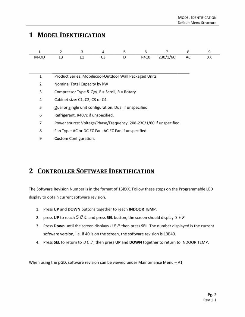
1 MODEL IDENTIFICATION
1 2 3 4 5 6 7 8 9
M-OD 13 E1 C3 D R410 230/1/60 AC XX
1 Product Series: Mobilecool-Outdoor Wall Packaged Units
2 Nominal Total Capacity by kW
3 Compressor Type & Qty. E = Scroll, R = Rotary
4 Cabinet size: C1, C2, C3 or C4.
5 Dual or Single unit configuration. Dual if unspecified.
6 Refrigerant. R407c if unspecified.
7 Power source: Voltage/Phase/Frequency. 208-230/1/60 if unspecified.
8 Fan Type: AC or DC EC Fan. AC EC Fan if unspecified.
9 Custom Configuration.
2 CONTROLLER SOFTWARE IDENTIFICATION
The Software Revision Number is in the format of 13BXX. Follow these steps on the Programmable LED
display to obtain current software revision.
1. Press UP and DOWN buttons together to reach INDOOR TEMP.
2. press UP to reach and press SEL button, the screen should display Stp
3. Press Down until the screen displays UE2 then press SEL. The number displayed is the current
software version, i.e. if 40 is on the screen, the software revision is 13B40.
4. Press SEL to return to UE2, then press UP and DOWN together to return to INDOOR TEMP.
When using the pGD, software revision can be viewed under Maintenance Menu – A1

CONTROLLER MENUS Default Menu Structure
Pg. 3 Rev 1.1
3 CONTROLLER MENUS
Certain fixes will require navigation through the controller to correct the appropriate settings. Use the
Menu Structure below as a guide to access the Main Menu and the various Sub Menus. For a;; two key
combinations, place a thumb between the two buttons and press the two keys at the exact same time.
You may always return to the main menu by pressing Up and Down at the same time.
3.1 Default Menu Structure
PGD Menu Structure
Note: The default password for the pGD is 3

CONTROLLER MENUS Sub Menus
Pg. 4 Rev 1.1
3.2 Sub Menus
A quick reference of the major functions and settings available in each of the sub menu is listed below.
Consult the WPU Installation and Operation Manual, available at http://tempesthvac.com/, for a
complete list of parameters.
Submenu Functions/Settings Available
C Menu
Temperature Setpoint
Component Running Status
Software Revision
System Time
Sensor Calibration
Manual Mode (System must be OFF)
Alarm History
D Menu
Test Mode
Input/Output Logic (Normally Open vs. Normally Closed)
Supply fan setting (AC vs. DC)
Generator run behavior setting
E Menu
High/Low Temp Alarm Setpoint
Lead Unit Operating Parameters
Controller and Controller Address Settings
Damper Actuator Alarm Settings
Reset Factory Default
L Menu
L01 – Component Running Status L02 – Component Start Count and Running Hours L03 – Current Controller Input/Output L04 – User Settings
Conditions for Free Cooling
Minimum Supply air Temperature
Remote Communicate Settings L05 – Manufacturer Settings
Turn on/off permanent circulation
Free Cool only during emergency (13B46 and up)
Turn off Free Cooling due to Dirty Filter Alarm
Lag Unit Operating Parameters
3.2.1 PGD Sub Menus
Submenu Functions/Settings Available
Maintenance
Review software and boot versions
View component Run Time and Start Count
Modify system time
Review Alarm History
Manual Operation mode
Calibrate sensor probes
Input/Out View current input/output status on the controller:
Setpoint Change primary temperature setpoint
User
Adjust cooling stages
Heater settings
Humidity control
Free Cooling settings
High/Low Temp alarm setpoints
Step Test (only when system is off)
Comfort Mode
Manufacturer
Communication settings
Alarm inputs (Normally Open vs. Normally Closed)
Supply fan setting (AC vs. DC)
Erase Alarm History
Reset factory defaults

ALARMS TROUBLESHOOTING Low Pressure Alarm (A02/A04)
Pg. 5 Rev 1.1
4 ALARMS TROUBLESHOOTING
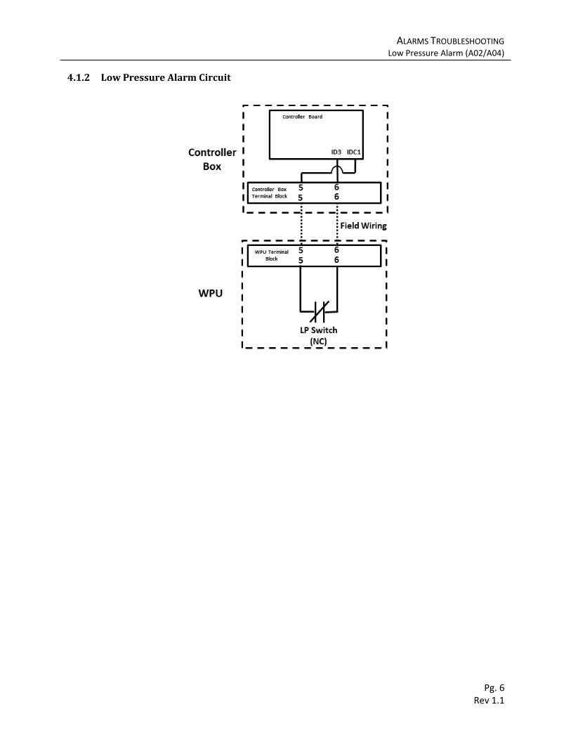
4.1 Low Pressure Alarm (A02/A04) A low pressure alarm indicates the controller has received an open signal from the normally closed low
pressure switch circuit. Three active alarms within one hour will trigger compressor lockout to protect
the refrigerant circuit. Lockout can be cleared by powered cycling the controller. The low pressure alarm
is bypassed for the first 60s of compressor startup (adjustable through F1P in L05 Menu or Manufacturer
Menu- cg).
4.1.1 Troubleshooting
Possible Cause Component to Check Recommended Action
Loose/incorrect alarm wiring
See Low Pressure Alarm Wiring below
If the low pressure switch is closed but the controller is receiving an open signal between ID3 and IDC1, verify/tighten alarm wiring according to diagram below
Compressor start at extreme low temperature
Low pressure bypass Low pressure bypass can be increased from default 60 seconds to 120seconds through F1P in L05 Menu or Manufacturer Menu - cg
Lack of refrigerant Low side pressure. Normal Ranges: R407C = 58-102 PSI R410A = 115-175 PSI
1. Restart controller to clear lockout 2. Leak check unit 3. Repair leak if any 4. Charge appropriate amount of refrigerant
Low pressure switch defective
Low pressure switch If switch is open when low side pressure is in normal range, replace the switch
Reduced airflow Supply fan Air Filter
Verify supply fan runs properly and air filter is clean. If the fan does not run correctly, refer to section A10/11
ALARMS TROUBLESHOOTING Low Pressure Alarm (A02/A04)
Pg. 6 Rev 1.1
4.1.2 Low Pressure Alarm Circuit

ALARMS TROUBLESHOOTING High Pressure Alarm (A03/A06)
Pg. 7 Rev 1.1
4.2 High Pressure Alarm (A03/A06) A high pressure alarm indicates the controller has received an open signal from the normally closed high
pressure switch circuit. 3 active alarms within one hour will trigger compressor lockout to protect the
refrigerant circuit. Lockout can be cleared by powered cycling the controller.
4.2.1 Troubleshooting
Possible Cause Component to Check Recommended Action
Condenser coil blockage
Condenser coil Wash/Clean condenser coil. Remove any blockage.
Loose/incorrect alarm wiring
High Pressure Alarm Wiring (see diagram below )
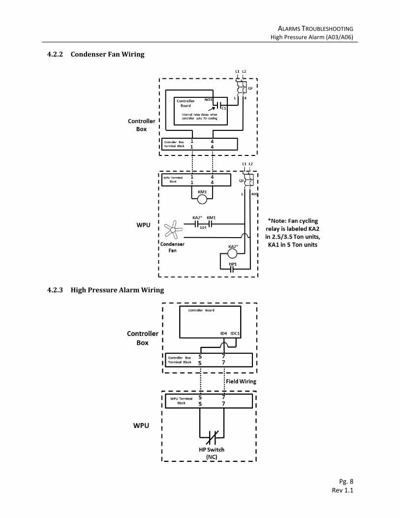
If the high pressure switch is closed but the controller is receiving an open signal between ID4 and IDC1, verify/tighten alarm wiring according High Pressure Alarm below
Condenser fan wiring Condenser fan wiring (see diagram below)
If condenser fan does not receive power across wire 120 and wire 400, verify/tighten condenser fan wiring according to Condenser
Fan Wiring below
Faulty condenser fan switch
High pressure switch for condenser fan (HP1)
If high pressure switch for condenser fan does not close properly, replace the switch.
Condenser fan relay condenser fan cycle relay (KA2 for 2.5/3.5 Ton model, KA1 for 5 Ton model)
If the fan cycling relay does not close when the coil is energized, replace the relay.
High Pressure Alarm Switch defective
High pressure alarm switch (HP) HP Switch opens at: R407C: 390/420PSI R410A: 600PSI
If switch is open when high side pressure is in normal range, replace the switch
Condenser fan failure Power at Condenser fan (240V across wire 120 and wire 400)
If condenser fan receives power but does not run, replace the condenser fan.
ALARMS TROUBLESHOOTING High Pressure Alarm (A03/A06)
Pg. 8 Rev 1.1
4.2.2 Condenser Fan Wiring
4.2.3 High Pressure Alarm Wiring

ALARMS TROUBLESHOOTING Smoke/Fire Alarm (A05)
Pg. 9 Rev 1.1
4.3 Smoke/Fire Alarm (A05)
The controller receives a normally closed signal (can be changed to normally open at SFT under D
Menu or Manufacturer Menu – C2a) from the smoke/fire detector on terminal 41 and 5. When the
controller receives an active smoke/fire alarm, all components on both units will shut to minimize
airflow within the site: outside air damper, heater, compressor, and supply fan. This alarm is reset
automatically when alarm is no longer active.
Note: The normally open or normally closed signal must be isolated relay contacts. Piggybacking with
other devices may cause false alarm.
4.3.1 Troubleshooting
Possible Cause Component to Check Recommended Action
Incorrect input signal setting SFT parameter in D Menu and input signal on terminal 41 and 5
Adjust SFT in D Menu to switch between normally open and normally closed alarm input. If using the pGD, this parameter can be accessed under Manufacturer Menu – C2a
Loose/incorrect alarm wire Smoke/Fire alarm wiring (see diagram below)
If the detector relay is closed but the controller is receiving an open signal between ID4 and IDC1, verify/tighten alarm wiring according Smoke Fire Alarm Wiring
below.
Smoke/Fire detector is falsely triggered
Smoke/Fire detector If defective, replace detector
4.3.2 Smoke Fire Alarm Wiring
ALARMS TROUBLESHOOTING High Temp Alarm (A07)
Pg. 10 Rev 1.1
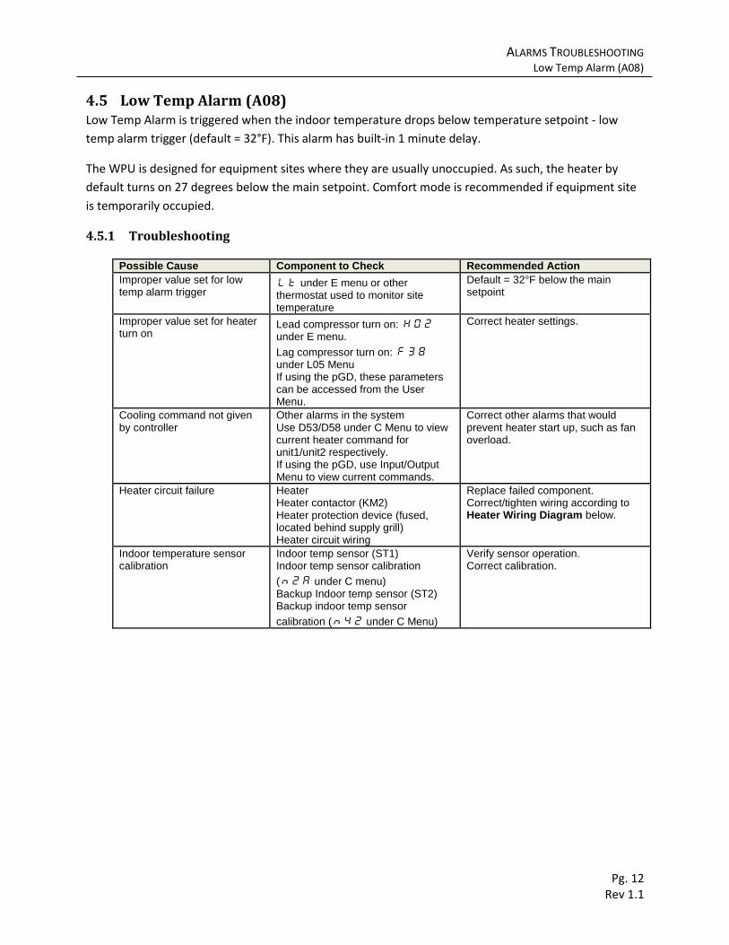
4.4 High Temp Alarm (A07) High Temp Alarm is triggered when the indoor temperature exceeds temperature setpoint + high temp
alarm trigger (default = 18°F). This alarm has a built-in 1 minute delay (can be eliminated at F35 under
L05 Menu).
4.4.1 Troubleshooting
Possible Cause Component to Check Recommended Action
Reduced cooling capacity
Filter, condenser coil, low side pressure Clean/wash filter and condenser. Remove blockage if appropriate. Leak check/ repair if low on refrigerant.
Improper value set for high temp alarm trigger
Ht under E menu or other thermostat used to monitor high temperature If using the pGD, this parameter can be accessed from User Menu – P8
Default = 18°F.
Undersized unit Check if the heat load of the site exceeds sensible capacity of the AC units
Add/Upgrade AC or remove unused equipment
Cooling command not given by controller
Check for other alarms present on controller. Use D52/D57 under C Menu to view current compressor command for unit1/unit2 respectively
Correct other alarms that would prevent compressor start up, such as high/low pressure lockout and smoke/fire alarm.
Improper value set for compressor turn on
Lead compressor turn on: C02 under E menu
Lag compressor turn on: F38 under L05 Menu If using the pGD, these parameter can be accessed under User Menu.
Correct compressor settings.
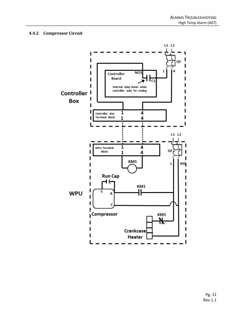
Compressor circuit failure
Compressor. Compressor contactor (KM1) Compressor run caps (C) Compressor circuit wiring
Replace failed component. Correct/tighten wiring according to Compressor Circuit diagram below
Indoor temperature sensor
Indoor temp sensor (ST1)
Indoor temp sensor calibration (N2A under C menu) Backup Indoor temp sensor (ST2)
Backup indoor temp sensor calibration (N42 under C Menu) If using the pGD, calibrations can be accessed in Maintenance Menu
Verify sensor operation. Correct calibration.
ALARMS TROUBLESHOOTING High Temp Alarm (A07)
Pg. 11 Rev 1.1
4.4.2 Compressor Circuit
ALARMS TROUBLESHOOTING Low Temp Alarm (A08)
Pg. 12 Rev 1.1
4.5 Low Temp Alarm (A08) Low Temp Alarm is triggered when the indoor temperature drops below temperature setpoint - low
temp alarm trigger (default = 32°F). This alarm has built-in 1 minute delay.
The WPU is designed for equipment sites where they are usually unoccupied. As such, the heater by
default turns on 27 degrees below the main setpoint. Comfort mode is recommended if equipment site
is temporarily occupied.
4.5.1 Troubleshooting
Possible Cause Component to Check Recommended Action
Improper value set for low temp alarm trigger
Lt under E menu or other thermostat used to monitor site temperature
Default = 32°F below the main setpoint
Improper value set for heater turn on
Lead compressor turn on: H02 under E menu.
Lag compressor turn on: F38 under L05 Menu If using the pGD, these parameters can be accessed from the User Menu.
Correct heater settings.
Cooling command not given by controller
Other alarms in the system Use D53/D58 under C Menu to view current heater command for unit1/unit2 respectively. If using the pGD, use Input/Output Menu to view current commands.
Correct other alarms that would prevent heater start up, such as fan overload.
Heater circuit failure Heater Heater contactor (KM2) Heater protection device (fused, located behind supply grill) Heater circuit wiring
Replace failed component. Correct/tighten wiring according to Heater Wiring Diagram below.
Indoor temperature sensor calibration
Indoor temp sensor (ST1) Indoor temp sensor calibration
(N2A under C menu) Backup Indoor temp sensor (ST2) Backup indoor temp sensor
calibration (N42 under C Menu)
Verify sensor operation. Correct calibration.

ALARMS TROUBLESHOOTING Low Temp Alarm (A08)
Pg. 13 Rev 1.1
4.5.2 Heater Wiring
ALARMS TROUBLESHOOTING DC Failover (A09)
Pg. 14 Rev 1.1
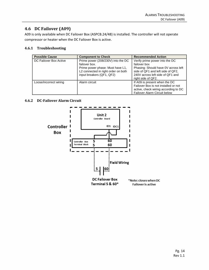
4.6 DC Failover (A09) A09 is only available when DC Failover Box (ASPCB.24/48) is installed. The controller will not operate
compressor or heater when the DC Failover Box is active.
4.6.1 Troubleshooting
Possible Cause Component to Check Recommended Action
DC Failover Box Active Prime power (208/230V) into the DC failover box. Prime power phase: Must have L1, L2 connected in right order on both input breakers (QF1, QF2)
Verify prime power into the DC failover box Phasing: Should have 0V across left side of QF1 and left side of QF2, 240V across left side of QF1 and right side of QF2.
Loose/incorrect wiring Alarm circuit If A09 is present when the DC Failover Box is not installed or not active, check wiring according to DC Failover Alarm Circuit below
4.6.2 DC-Failover Alarm Circuit

ALARMS TROUBLESHOOTING Evaporator Fan Overload/AC Loss (A10/A11)
Pg. 15 Rev 1.1
4.7 Evaporator Fan Overload/AC Loss (A10/A11) The normally closed evaporator overload feedback opens at terminal 5 & 9 when either the supply fan
has been physically blocked or that it does not receive the correct power supply (208/230VAC +/- 10%).
This alarm also serves as a warning when no power is applied to the WPU.
Note: Evaporator Overload alarm only applies to AC powered supply fans. If this alarm is display when
the power supply for the fan is DC, change the fan setting SF1 in D menu from 1 to 0. See Chapter 2
Model Identification to determine supply fan power input.
4.7.1 Troubleshooting
Possible Cause Component to Check Recommended Action
No power input to the system Verify 208/230VAC at the input breaker (QF)
Turn on breaker/power supply. Correct
No power input to the supply fan Verify 208/230VAC across wire 401/402 for 5 Ton model and 401/400 for other models. Verify Evap. Fan
Correct wiring. Replace fan relay if faulty.
Loose/incorrect feedback wiring Alarm wiring Refer to Fan Overload Alarm Wiring Below
Faulty overload switch Normally closed overload output (two white wires coming from the supply fan)
If 208VAC is verified going into the supply fan and the two white wires connecting to 5 and 9 are still open, replace the fan

ALARMS TROUBLESHOOTING Evaporator Fan Overload/AC Loss (A10/A11)
Pg. 16 Rev 1.1
4.7.2 Fan Overload Alarm Wiring

ALARMS TROUBLESHOOTING Dirty Air Filter (A15/A16)
Pg. 17 Rev 1.1
4.8 Dirty Air Filter (A15/A16) If the air filter is dirty, excess pressure will build up across the filter, triggering the normally closed air
pressure switch (PF) to open.
4.8.1 Troubleshooting
Possible Cause Component to Check Recommended Action
Dirty Air Filter Air filter. Open the middle-front panel to access the filters.
Replace air filter
Incorrect wiring Alarm wiring Correct wiring. Refer to Dirty Air Filter Alarm Wiring below
Incorrect air pressure switch setting
Arrow on the dial should be pointing at 250
Correct setting to 250
Faulty air pressure switch Air pressure switch If the switch is open while the filter is clean and setting is correct, replace the switch
4.8.2 Dirty Air Filter Alarm Wiring
ALARMS TROUBLESHOOTING pLAN alarm (A17)
Pg. 18 Rev 1.1
4.9 pLAN alarm (A17) pLAN is the communication wire between unit 1 and unit 2 controller board. The units will act
independently when the communication is lost.
4.9.1 Troubleshooting
Possible Cause Component to Check Recommended Action
Loose connector pLAN connector on J6 block at each controller board
Push in connector
Incorrect Controller Address CAD under E menu. CAD must be 1 for unit 1 and 2 for unit 2
Correct setting. Move the display connector (J7) to unit 2 to configure unit 2 address
Controller board failure/power loss
24VDC on across J1 Power supply LED light between J8 and J9 should be lit
Secure power input connector. Replace controller board is power is present but controller board does not power on. Refer to Controller board LED status below
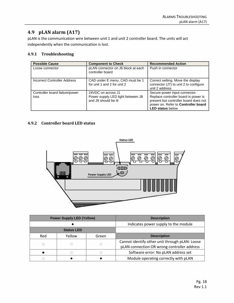
4.9.2 Controller board LED status
Power Supply LED (Yellow) Description
● Indicates power supply to the module Status LED
Red Yellow Green Description
◌ ◌ ◌ Cannot identify other unit through pLAN: Loose pLAN connection OR wrong controller address
● ◌ ◌ Software error: No pLAN address set
◌ ● ● Module operating correctly with pLAN

ALARMS TROUBLESHOOTING Clock Card Alarm (A18)
Pg. 19 Rev 1.1
4.10 Clock Card Alarm (A18) Clock Card Alarm occurs when the clock card is loose or its battery has drained. Clock card is able to
track system time even when the system is not powered for up to 8 months at a time. The battery is
recharged when the system is powered again. The clockcard is located below the J6 pLAN block on the
top left of the controller board.
4.10.1 Troubleshooting
Possible Cause Component to Check Recommended Action
Loose clockcard Clock card Push in connector
Defective clockcard/battery Clock card Replace Clock Card
4.11 Humidity Sensor Alarm (A19) In software version 13B40 and below humidity Sensor alarm occurs when the humidity exceeds 90% or
when the sensor is disconnected. Humidity alarm only occurs if the sensor is disconnected in software
versions after 13B40.
4.11.1 Troubleshooting
Possible Cause Component to Check Recommended Action
Low heat load, site cools down without compressor
Free cooling humidity limit (U04 in L04 Menu)
Change to 80%. For extremely small heat load site, change to 60%.
Loose/incorrect sensor wire
Sensor wire Correct wiring. Refer to Humidity Sensor Wring below
Defective humidity sensor Humidity sensor Replace Humidity Sensor
4.11.2 Humidity Sensor Wring

ALARMS TROUBLESHOOTING Temp Sensor Alarm (A20/A21/A22/A26/A27)
Pg. 20 Rev 1.1
4.12 Temp Sensor Alarm (A20/A21/A22/A26/A27) Temperature sensor alarms occur when the sensor is defective or disconnected. Temp sensors are not
orientation sensitive and can be connected in both ways.
4.12.1 Troubleshooting
Possible Cause Component to Check Recommended Action
Temperature sensor disconnected/loose
Wire connection Refer to Temp Sensor Wiring below.
Temperature sensor Defective or wire broken
Sensor and wiring. Use the main menu to check current sensor readings
Replace irresponsive sensor after wiring is verified
4.12.2 Temp Sensor Wiring
4.13 Two Compressor Run (A23) Two Compressor Run alarm occurs whenever the two units are required to use mechanical cooling at
the same time. This alarm is an early warning that one of the unit may have reduced its cooling capacity.
4.13.1 Troubleshooting
Possible Cause Component to Check Recommended Action
Reduced capacity on one unit
Air filter, condenser, refrigerant charge Replace filter, clean condenser, and recharge refrigerant.
One unit unable to use mechanical cooling due to other alarms
Check whether mechanical cooling is locked out due to
Correct other alarms first
Shelter heat load exceed one unit’s sensible capacity
Shelter heat load, unit sensible capacity Add/upgrade unit. Remove unused equipment.
Exceptional high outdoor temperature
Air leaks, passive ventilation Minimize air exchange during hot weather reduces total heat load
Improper lag unit turn on point
F38 under L05 Menu Recommended at least 5F for F38
Label Description
ST1 Indoor Temp
ST1’ Backup Indoor
ST2 Outdoor Temp
ST3 Unit 1 Supply Temp
ST3’ Unit 2 Supply Temp
ALARMS TROUBLESHOOTING Damper Alarm (A24/A25)
Pg. 21 Rev 1.1
4.14 Damper Alarm (A24/A25) The controller verified proper damper positioning by comparing the supply air temperature with
outdoor/indoor temperature. If the damper should be completely open, the supply temperature should
be the same as the outdoor temperature within a tolerance (configurable at FC2 under E Menu). If the
damper should be completely closed, the supply temperature should be the same as indoor
temperature within in tolerance (configurable at FC3 under E menu).
4.14.1 Troubleshooting
Since the controller checks the damper by comparing temperatures, improper setup of the temperature
sensors can cause erroneous alarm. Verify each damper’s physical movement through the step test. If
the damper behaves correctly, refer to Sensor Setup Correction below. If the damper does not behave
correctly, move to Damper Fail section below.
Sensor Setup Correction
Possible Cause Component to Check Recommended Action
Incorrect supply air temperature setup
St3 must be in the supply air stream of unit 1. St3’ must be in the supply air
stream of unit 2.
Correct temperature setup. Refer to Temp Sensor Wiring on page 20
Insufficient temperature tolerance
FC2/3 under E menu Increase to 15-20F
Improper outdoor temp sensor placement
Outdoor temp sensor box must be placed in the shade. Indoor air leakage through the wall into the sensor box
Move the outdoor sensor box into shade. Seal the air leakage
Damper Fail
Possible Cause Component to Check Recommended Action
Tightening nuts on damper actuator loose
Nuts on damper actuator. Damper actuator can be accessed from the damper inspection panel on the side of the unit.
Tighten down.
Loose/incorrect damper actuator wiring
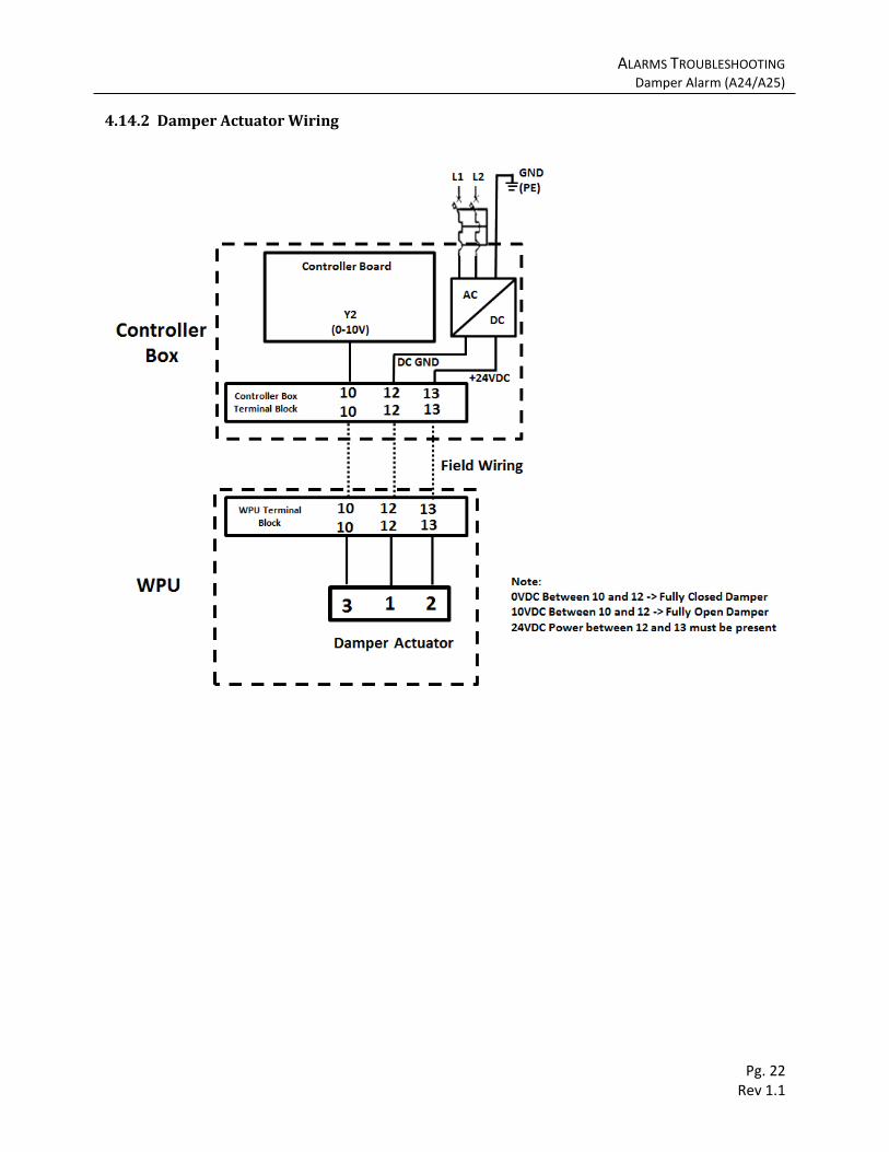
Damper wiring: 24VDC between 12 and 13 for power, 10VDC between 10 and 12 for open position.
Correct wiring. Refer to Damper Actuator Wiring below
Incorrect damper actuator setting
Check if damper actuator is moving in reverse direction
Correct setting. The black round dial on the face of the damper actuator must be set to 0.
ALARMS TROUBLESHOOTING Damper Alarm (A24/A25)
Pg. 22 Rev 1.1
4.14.2 Damper Actuator Wiring

ALARMS TROUBLESHOOTING Generator Run (A28)
Pg. 23 Rev 1.1
4.15 Generator Run (A28) The controller receives a normally open signal (can be changed to normally close at DGt under the D
Menu) from the generator on terminal 42 and 5. When the controller receives an active generator run
signal, free cooling will be shut down and as well as the lag unit. For large generators, the lag unit can be
enabled during generator run at E2C under the D Menu. The compressors will also engage a 3minute
delay when the generator turns on/off. Delay duration can be configured at CSt under the D Menu
4.15.1 Troubleshooting
Possible Cause Component to Check Recommended Action
Generator is running Generator n/a
Incorrect input signal setting DGt parameter in D Menu and input signal on terminal 42 and 5
Adjust DGt in D Menu to switch between normally open and normally closed alarm input
Loose/incorrect alarm wire Alarm wiring Verify/tighten alarm wiring according Generator Wiring below.
ALARMS TROUBLESHOOTING DC Fan Air Flow Alarm (A29/A30)
Pg. 24 Rev 1.1
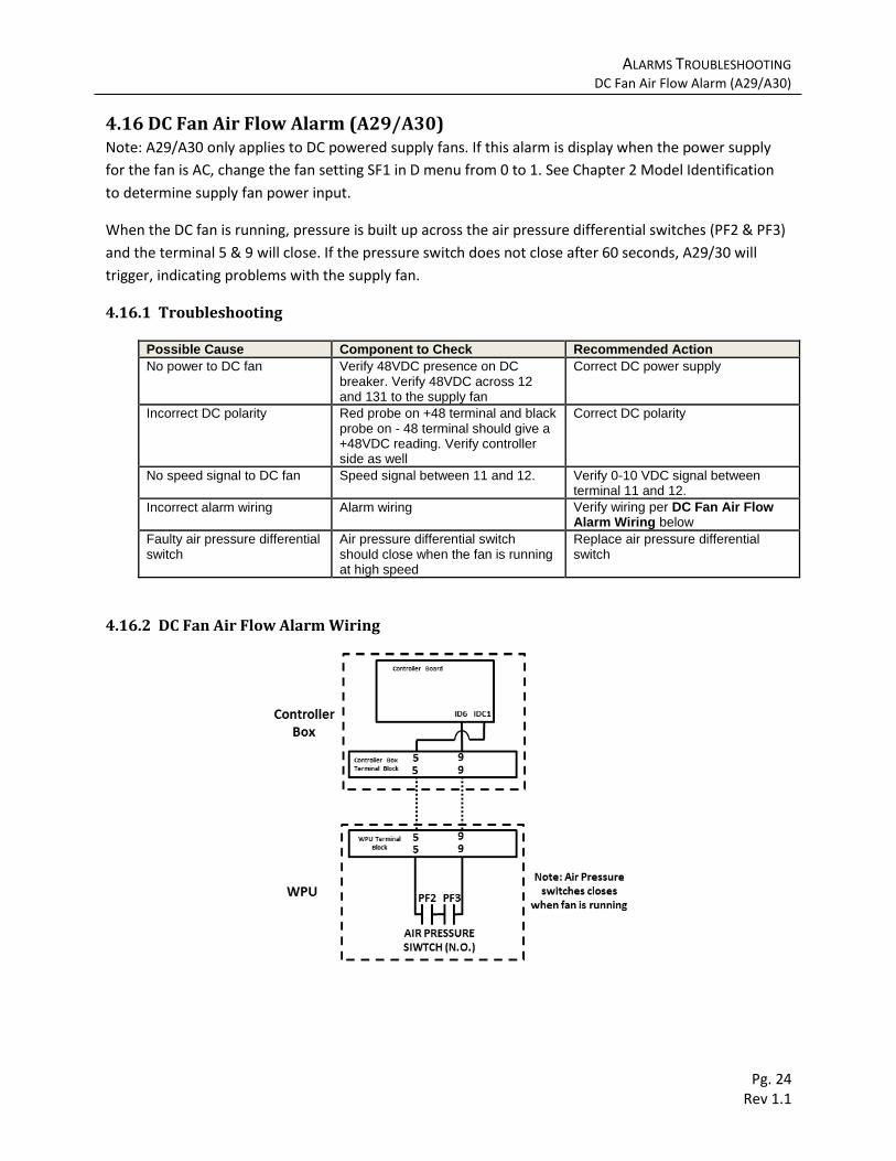
4.16 DC Fan Air Flow Alarm (A29/A30) Note: A29/A30 only applies to DC powered supply fans. If this alarm is display when the power supply
for the fan is AC, change the fan setting SF1 in D menu from 0 to 1. See Chapter 2 Model Identification
to determine supply fan power input.
When the DC fan is running, pressure is built up across the air pressure differential switches (PF2 & PF3)
and the terminal 5 & 9 will close. If the pressure switch does not close after 60 seconds, A29/30 will
trigger, indicating problems with the supply fan.
4.16.1 Troubleshooting
Possible Cause Component to Check Recommended Action
No power to DC fan Verify 48VDC presence on DC breaker. Verify 48VDC across 12 and 131 to the supply fan
Correct DC power supply
Incorrect DC polarity Red probe on +48 terminal and black probe on - 48 terminal should give a +48VDC reading. Verify controller side as well
Correct DC polarity
No speed signal to DC fan Speed signal between 11 and 12. Verify 0-10 VDC signal between terminal 11 and 12.
Incorrect alarm wiring Alarm wiring Verify wiring per DC Fan Air Flow Alarm Wiring below
Faulty air pressure differential switch
Air pressure differential switch should close when the fan is running at high speed
Replace air pressure differential switch
4.16.2 DC Fan Air Flow Alarm Wiring
ALARMS TROUBLESHOOTING AC Loss for DC Fan Systems (A31/A32)
Pg. 25 Rev 1.1
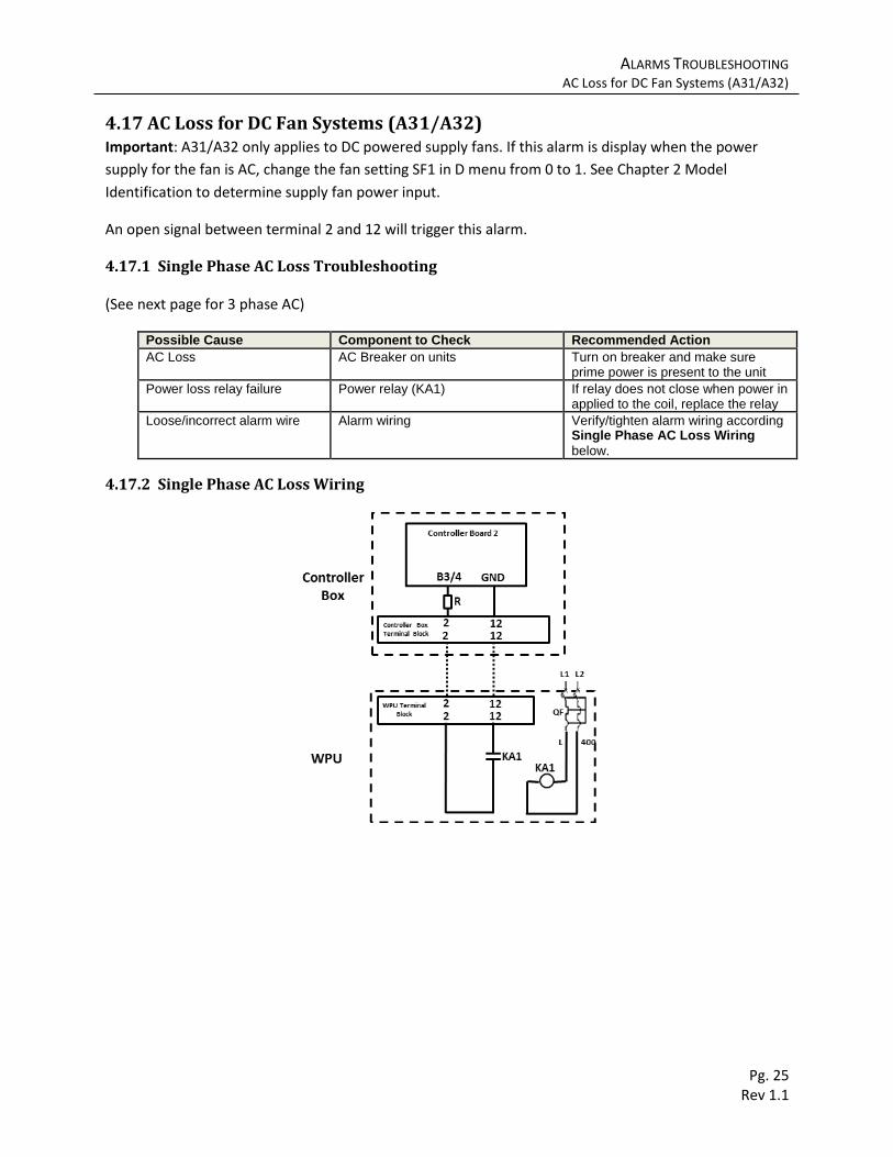
4.17 AC Loss for DC Fan Systems (A31/A32) Important: A31/A32 only applies to DC powered supply fans. If this alarm is display when the power
supply for the fan is AC, change the fan setting SF1 in D menu from 0 to 1. See Chapter 2 Model
Identification to determine supply fan power input.
An open signal between terminal 2 and 12 will trigger this alarm.
4.17.1 Single Phase AC Loss Troubleshooting
(See next page for 3 phase AC)
Possible Cause Component to Check Recommended Action
AC Loss AC Breaker on units Turn on breaker and make sure prime power is present to the unit
Power loss relay failure Power relay (KA1) If relay does not close when power in applied to the coil, replace the relay
Loose/incorrect alarm wire Alarm wiring Verify/tighten alarm wiring according Single Phase AC Loss Wiring
below.
4.17.2 Single Phase AC Loss Wiring
AC Loss for DC Fan Systems (A31/A32)
Pg. 26 Rev 1.1
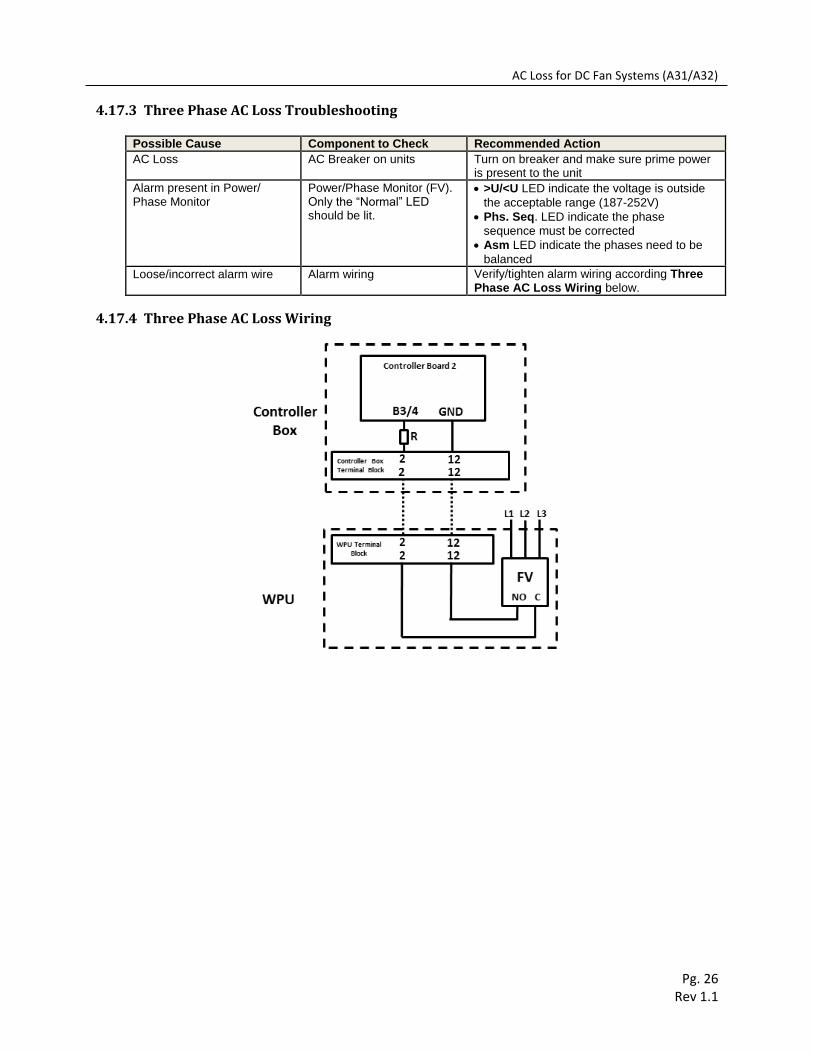
4.17.3 Three Phase AC Loss Troubleshooting
Possible Cause Component to Check Recommended Action
AC Loss AC Breaker on units Turn on breaker and make sure prime power is present to the unit
Alarm present in Power/ Phase Monitor
Power/Phase Monitor (FV). Only the “Normal” LED should be lit.
>U/<U LED indicate the voltage is outside
the acceptable range (187-252V)
Phs. Seq. LED indicate the phase
sequence must be corrected
Asm LED indicate the phases need to be
balanced
Loose/incorrect alarm wire Alarm wiring Verify/tighten alarm wiring according Three Phase AC Loss Wiring below.
4.17.4 Three Phase AC Loss Wiring

SYMPTOMS WITH NO ALARMS System function
Pg. 27 Rev 1.1
5 SYMPTOMS WITH NO ALARMS
5.1 System function In some cases, such as incorrect/loose alarm wiring, system symptoms can exist with no active alarm.
Use the step test and test all system functions. If certain function does not work properly, the
troubleshooting sections outlined below can be used to troubleshooting these components.
Component not working properly Refer to section
Supply fan AC Fan: A10/A11 Evap. Fan OL
DC Fan: A29/A30 DC Fan Air Flow Alarm
Heater A08: Low Temp Alarm
Compressor A07: High Temp Alarm
Damper A24/25 Damper Alarm
5.2 No Controller Display
Possible Cause Component to Check Recommended Action
Loose display connector Display connector (white connector on the J7 terminal)
Apply force to push in connector firmly on both ends.
Display safety trip Overvoltage over normal or generator operation
Reset controller power. If issue persist regularly, verify generator voltage: 187-252VAC
No power to controller Power Supply LED/ J1 connector
Verify 24VDC Power supply across J1connector (orange). If LED is still dark after DC power is verified and no physical damage on J1 connector, replace the controller.
5.2.1 Controller Power Supply LED