Airport Visual Aid Technologies - International Civil …€¦ · · 2013-09-14Federal Aviation...
115
Federal Aviation Administration Airport Visual Aid Technologies ICAO Workshop on Air Navigation Visual Aids New Technologies May 7-11, 2012 ICAO South American Regional Office Lima, Peru Presented by Alvin Logan FAA AAS-100
-
Upload
truonghanh -
Category
Documents
-
view
214 -
download
0
Transcript of Airport Visual Aid Technologies - International Civil …€¦ · · 2013-09-14Federal Aviation...

Federal Aviation Administration Airport Visual
Aid Technologies
ICAO Workshop on Air
Navigation Visual Aids
New Technologies
May 7-11, 2012
ICAO South American
Regional Office
Lima, Peru
Presented by Alvin Logan
FAA AAS-100

AGENDA
• Mixing of Light Source Technologies
• Load Characteristics
• Electrical Noise from Other Airfield Components
• Electronic Devices Can Provide a Non-Linear or Reactive Load
• EB-67 Light Sources Other Than Incandescent and Xenon for Airport and Obstruction Light Fixtures

AGENDA
• Obstruction Lighting Equipment
• Light Fixture Performance Criteria
• Intensity of a Fixture With an Alternative Light Source
• Chromaticity – Fixture Daytime Viewing
• LED Light Fixture Testing
• Innovative and Energy-Saving Product Utilizing LED Light Source

Mixing of Light Source Technologies

Mixing of Light Source Technologies
AC 150/5340-30F, para 1.4

• There are concerns regarding the interspersion of LED light fixtures and incandescent filament lamps.
• Intensity requirements are the same. However: – LED fixtures may be perceived as having a difference in
color saturation and/or brightness.
– Results in distortion of the visual presentation to the pilot.
– Due to the LED emitting essentially a narrow frequency range light signal.
• Added paragraph 1.4 “Mixing of Light Source Technologies” to AC 150/5340-30E to prohibit interspersion of dissimilar technologies.
Mixing of Light Source Technologies
Mixing of Light Source Technologies
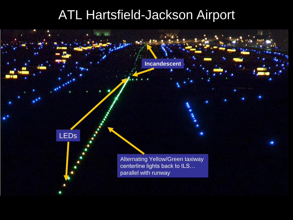
Alternating Yellow/Green taxiway
centerline lights back to ILS…
parallel with runway
LEDs
Incandescent
ATL Hartsfield-Jackson Airport

Raleigh Durham(RDU) Approach
LED RCLs and TDZs Incandescent HIRLs
Incandescent MALSR

LED Flight Testing at
Raleigh Durham (RDU) North Carolina
Incandescent HIRLs
LED TDZs LED RCLs

• Touchdown Zone Lights
• Runway Edge Lights including Threshold, End and Stopway
• Runway Guard Lights – Each pair of elevated RGLs must be the same technology.
For in-pavement lights, do not mix LED with incandescent fixtures in the same bar.
• Signs per location – Do not collocate LED signs with incandescent signs.
Example: runway holding position signs on both sides of a taxiway, holding position signs on both sides of a runway, separate signs that form a sign array.
Mixing of Light Source Technologies

• Taxiway curved segments (centerline and edge)
• Taxiway Straight Segments (centerline and edge)
• Approach Lighting Systems
• Stop Bars
• Runway Centerline
• Rapid Exit Taxiway Indicator Lights (RETIL) (up until the holding position or runway vacated position)
• Precision Approach Path Indicator (PAPI)
Mixing of Light Source Technologies

Load Characteristics
• AC 150/5340-30F
– Appendix A6-2.7. Load characteristics
• Most addressable devices are designed to handle incandescent loads. Generally, circuit current is checked to the load. If other types of loads (for example, LED or flashing) are to be used, consult the manufacturer to determine compatibility.
Load Characteristics

• Power line carrier (PLC) manufacturers do not guarantee that their products are compatible with LED fixture as a plug in (similar to an incandescent).
• The circuitry in the PLC unit expects a “resistive load” similar to an incandescent lamp.
• Some LED fixtures have switching supplies and other electronics on the input.
Load Characteristics

Load Characteristics
• The effective impedance on the "front end" of the fixture changes depending on what the supply is doing. – If the hardware is looking for continuity similar to
using an ohmmeter, it expects current to flow in the lamp.
– The amount of current may not be what is expected if the impedance is switching around in real time.
• In some cases it might work, but the way the front end behaves is not specified and the way PLC modules detect lamp failure is not published or standardized.
Electrical Noise from Other Airfield Components

Electrical Noise from Other Airfield Components
• AC 150/5340-30F – A6-2.4.1. Systems using power line carrier communications. The cable layout design for the series lighting circuit must be considered. – The optimal layout of the cable can maximize communications
performance and improve communications noise and interference operating margins. For new installations, separating the series circuit from other circuits on the airfield may improve communications reliability.
– The prevention of undesirable crosstalk arising from coupling from one cable to another is of importance. Electrical noise from other airfield components (i.e., CCRs, LED fixtures, certain types of signs of flashing lights) can also interfere with reliable communication. The designer should consult with the manufacturer to develop the best cable layout design.

• Strong EMI limits are required to obtain certification per Engineering Brief 67D. – 2.11 Electromagnetic Emissions - The alternate
light source fixture and associated on-board circuitry must meet Federal Communications Commission (FCC) Title 47, Subpart B, Section 15, "Unintentional Radiators", regulations concerning the emission of electronic noise. Both conducted and radiated emission limits must be tested.
• These requirements are currently in effect.
Electrical Noise from Other Airfield Components

Electrical Noise from Other Airfield Components
• Updated EB-67 to include Title 47, Part 15, Subpart B, Incidental Radiator, classification, and testing for conducted and radiated interference.

Electrical Noise from Other Airfield Components
• Updated FAA AC 150/5345-10 to include Title 47, Part 15, Subpart B, Incidental Radiator, classification, and testing for conducted and radiated interference.

• DOT/FAA/AR-TN05/10 – “Light Emitting Diode Taxiway Edge Lights Emissions Evaluation”
– Study conducted to evaluate taxiway edge light fixtures utilizing light emitting diode (LED) technology to determine:
• (1) If electrical emission levels from these fixtures are sufficient to cause interference to airfield circuits and warrant further investigation and
• (2) If there is a need to change the certification requirements for these electrical emissions.
Electrical Noise from Other Airfield Components
• Testing only performed on LED Taxiway Edge Lights
– Relatively low power
• Runway Center/Edge Lights are much higher power
– More likely to have PWM noise
• Future consideration
Electrical Noise from Other Airfield Components

Electronic Devices Can Provide a Non-Linear or Reactive Load

Appendix A6-3.5 of AC 150/5340-30F
• Electronic devices such as LED fixtures, style 2 and 3 signs, and addressable components, can provide a non-linear or reactive load on the circuit. These devices can include switching power supplies which may impart a capacitive characteristic to the circuit load. In addition, when the circuit is energized, these devices can initially appear to provide a relatively high voltage drop and suddenly change to a lower drop. The designer should consult with the CCR and electronic component manufacturer to determine if there are compatibility issues to consider.
Electronic Devices Can Provide a Non-Linear or Reactive Load

• A non-linear or reactive type load typically results in a lower fixture input Power Factor.
• More rigorous Power Factor requirements will be required as of the Effective Date of EB67D.
• Specified in paragraph 2.5.1 “Light Fixture Power Factor” – The true power factor for all fixtures powered by a
Constant Current Regulator must not be less than 0.7 when measured at the isolation transformer primary input power leads of the fixture on all constant current regulator current steps.
• Increasing the Power Factor requirements reduces the risk of interoperability issues between system components.
Electronic Devices Can Provide a Non-Linear or Reactive Load

Electronic Devices Can Provide a Non-Linear or Reactive Load
• Several airports have reported erratic operation from the constant current regulator caused by atypical circuit loads.
• An initial investigation proposed there may be compatibility issues with the airfield lighting circuit when using the combination of LED taxiway edge lights and Style 2/3 runway or taxiway signs.

• Signs may be placing an unusually high demand of charging current that the constant current regulator is not capable of delivering.
– Resulting action is the inability of the airfield lighting circuit to achieve all desired light intensities at the various step settings.
Electronic Devices Can Provide a Non-Linear or Reactive Load

Electronic Devices Can Provide a Non-Linear or Reactive Load
L-858 Style 2/3 With Internal Power Supply
LED
LED

• Style 2 lighted signs are for circuits powered by a 3 step constant current regulator (CCR) where the sign input current ranges from 4.8 to 6.6 amps.
• Style 3 lighted signs are for circuits powered by a 5 step CCR where the sign input current ranges from 2.8 to 6.6 amps
Electronic Devices Can Provide a Non-Linear or Reactive Load

• Signs may be installed on a circuit that also has other lighting fixtures that must have their brightness controlled by selecting CCR current steps.
• Signs are required to maintain their brightness at 10 to 30 foot lamberts.
• The sign lamp intensity must remain constant independent of the CCR current setting.
Electronic Devices Can Provide a Non-Linear or Reactive Load

• The issue occurs when varying the intensity of the lighting fixtures (at lower steps) while having to maintain the sign brightness between 10 – 30 foot-lamberts.
• The CCR has to deliver more voltage to the circuit to maintain the sign brightness at the same time providing a low intensity setting to the LED taxi fixtures.
Electronic Devices Can Provide a Non-Linear or Reactive Load

• Therefore, the sign power supply must continue to provide the same wattage to the load when the CCR current is changed to a lower step (to dim the lighting fixtures).
• The sign power supply will require more input voltage from the circuit when the circuit current decreases to continue to supply the load with the same wattage.
Electronic Devices Can Provide a Non-Linear or Reactive Load

Power Factor
• The power factor was measured for the circuit containing the LED taxiway edge light fixtures at Griffiss AFB. – pf = 0.23

What Causes Low Power Factor in Electrical Systems?
• Various causes, which can be attributed for low PF, may be listed as follows. – Inductive loads, especially lightly loaded
motors, and transformers.
– High Voltage
• The reactive power required by these loads increases the amount of apparent power in the distribution system and this increase in reactive power and apparent power results in a lower power factor.

• Airports with reported failed LED taxiway edge lights manufactured by Airport Lighting Company.

0
1
2
3
4
Typical voltage waveform in an AC circuit

PF is 1.0
0
1
2
3
4
Voltage and current in phase with respect to time
V and I in phase

PF is 0.5
0
1
2
3
4
Delay

Airport Series Lighting Systems
• Until recently, airport runway/taxiway lights and signs used incandescent light sources (an electrically heated filament) that is primarily a resistive load on the constant current regulator (CCR).
• Most light emitting diode light fixtures and signs use a power supply that conducts current in short pulses.
• The rapid changes in current vs. time for the power supply can generate harmonic currents in the series lighting power system.

Examination of Griffiss AFB LED Fixture
Damaged Rectifier Diodes and PCB in Fixture #3
A visual inspection the electronics revealed 2 rectifier diodes that appeared to be damaged by over-heating. Partially melted lead and solder extrusion from the damaged circuit board on the diode within the green circle.

• As power factor decreases, the delay
between the current and voltage increases,
which causes elevation in current.
• It takes more current flow to deliver the
same amount of power with a degrading pf.
Power Factor

Transients/Spikes/Surges
• Refers to short duration (less than 1 cycle) events. – Low frequency transients are often called
“capacitor switching transients”.
– High frequency transients are often called impulses, spikes, or surges.
• They can be caused when a discharged power-factor-correction capacitor is switched on across the line.
• High frequency transients are caused by lightning, and by inductive loads turning off.

New CCR Technology
• Single-phase constant current regulators, have been designed to provide power to airport lighting series circuits to assure sinusoidal current
– high power factor
– elevated efficiency
– low total harmonic distortion
– also in case of very low load

Engineering Brief 67
Light Sources Other than Incandescent and Xenon for Airport and Obstruction Lighting Fixtures

• Provides additional requirements for "Light Sources Other Than Incandescent and Xenon for Airport and Obstruction Lighting Fixtures" subject to certification under AC 150/5345-53, Airport Lighting Equipment Certification Program, and/or other applicable documents
• Inclusive to design requirements specified in AC 150/5345-46D, “Runway and Taxiway Light Fixtures”
Engineering Brief-67 “Light Sources Other Than Incandescent and Xenon for Airport and
Obstruction Light Fixtures”

• A minimum power factor of 0.8 is added in paragraph 2.2.
• A rated fixture lifetime is added in paragraph 2.5.
• A life test per AC 150/5345-53C, Appendix V is added.
• Lightning protection is changed from location category C1 to C2 in paragraph 2.13.
• Paragraph 2.18 is added for requirement to separate lightning protection system grounds from equipment grounds.
Changes To Engineering Brief 67B

• 2.2 Power Factor – The power factor for all fixtures must not be less than 0.8 when measured at the isolation transformer primary leads.
• Power Factor = Cosine of phase angle between voltage and current.
• Power factor has no units.
• The value of PF ranges from 0 to 1.
• Loads that are only resistive (no capacitance or inductance) have a PF of 1.
Changes To Engineering Brief 67B

• 2.5 Rated Life - Alternative light sources must have a minimum rated life of two years (this is inclusive of any electronics).
Changes To Engineering Brief 67B

• 2.6 Life Test A life test (inclusive of any drive electronics) that addresses the light emitter technology shall be conducted per AC 150/5345-53C, Appendix V for all alternative lighting device light fixtures under third party certification body cognizance.
Changes To Engineering Brief 67B
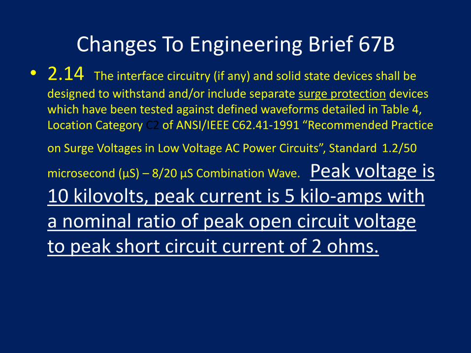
• 2.14 The interface circuitry (if any) and solid state devices shall be
designed to withstand and/or include separate surge protection devices which have been tested against defined waveforms detailed in Table 4, Location Category C2 of ANSI/IEEE C62.41-1991 “Recommended Practice
on Surge Voltages in Low Voltage AC Power Circuits”, Standard 1.2/50
microsecond (µS) – 8/20 µS Combination Wave. Peak voltage is 10 kilovolts, peak current is 5 kilo-amps with a nominal ratio of peak open circuit voltage to peak short circuit current of 2 ohms.
Changes To Engineering Brief 67B

• 2.18 The equipment manufacturer must clearly state in their installation instructions that under no circumstances should the building/tower lightning protection system down conductors be used as an equipment ground or otherwise connected to the tower lighting system.
Changes To Engineering Brief 67B

Engineering Brief 67C Updates
• EB 67C, Light Sources Other than Incandescent and Xenon for Airport and Obstruction Lighting Fixtures (1/7/2011)
• Defined new dimming curve for white light
• Redefined aviation white chromaticity boundaries
• Alternative lighting fixture accelerated life test
• Alternative light fixture power factor and method of determination
• Include new Category C2 surge protection requirements
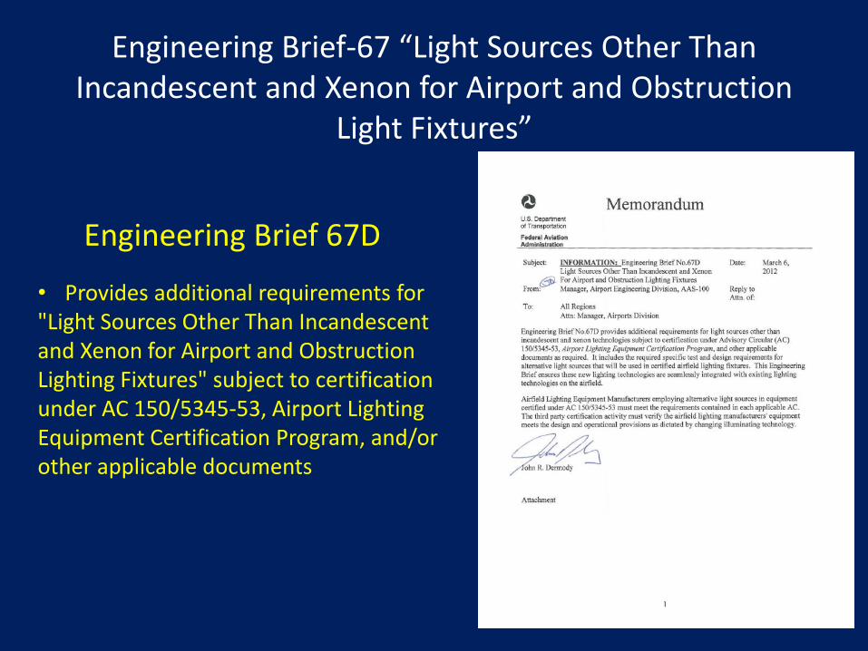
Engineering Brief 67D
• Provides additional requirements for "Light Sources Other Than Incandescent and Xenon for Airport and Obstruction Lighting Fixtures" subject to certification under AC 150/5345-53, Airport Lighting Equipment Certification Program, and/or other applicable documents
Engineering Brief-67 “Light Sources Other Than Incandescent and Xenon for Airport and Obstruction
Light Fixtures”
LED Runway Lighting Flight Check Raleigh-Durham N.C. (RDU)

• Raleigh-Durham International Airport Runway Lighting System Study
– Commercial Pilots Reported “Bright” LED Runway Centerline and Touchdown Zone Lights
– FAATC Visual Guidance Program and supporting personnel traveled to RDU on November 17, 2010 to conduct an examination of this brightness issue
– Lowered intensity settings for CCR Current Steps 1 and 2
Engineering Brief-67 “Light Sources Other Than Incandescent and Xenon for Airport and
Obstruction Light Fixtures”

LED Flight Testing at Raleigh Durham (RDU)

LED RCLs at RDU
LED Runway Centerline Lights
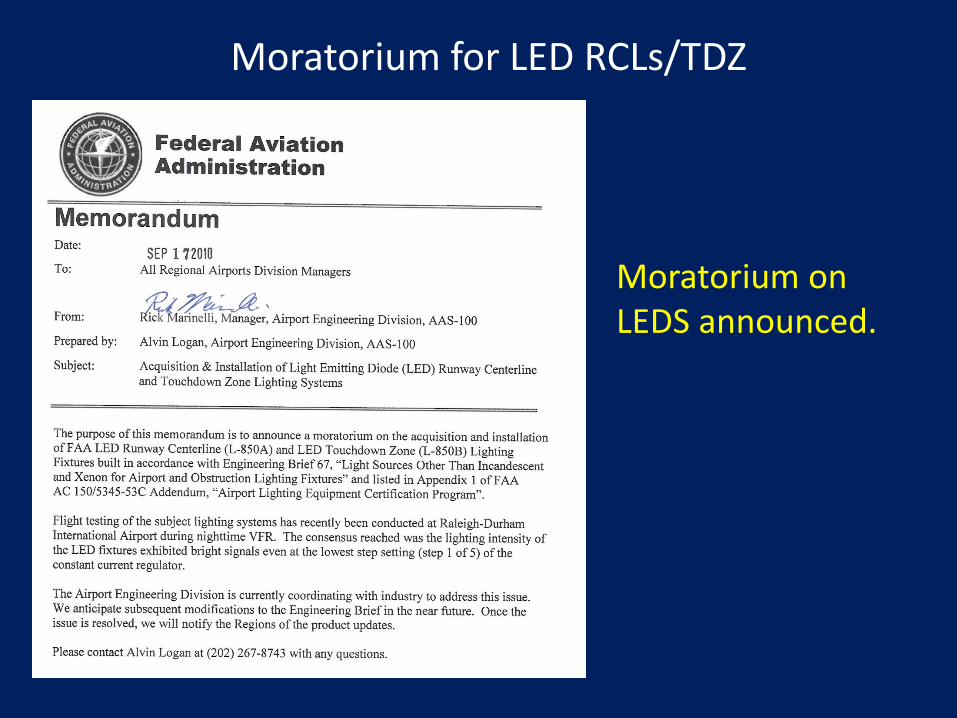
Moratorium for LED RCLs/TDZ
Moratorium on LEDS announced.

• All LED light fixtures with the exception of obstruction lighting (AC 150/5345-43) must be warranted by the manufacturer for a minimum of 4 years after date of installation inclusive of all electronics.
• All LED type fixtures shall be designated as “L-XXX(L)”
• Example: The LED version of the taxiway edge light type will be specified as "L-861T(L)".
Engineering Brief 67D Updates

• “Where a light fixture type is available as both incandescent (L-XXX) or LED (L-XXX(L)), the owner must select the fixture type to be used, or must specify that either incandescent or LED are acceptable.”
Engineering Brief 67D Updates

LED Program Guidance Letter

• Program Guidance Letter (PGL) has been prepared to discuss the impact of Engineering Brief (EB) 67D on AIP funded projects.
• Sponsor must specify either LED or incandescent.
• A life cycle cost analysis will no longer be required to permit the selection and use of LED fixtures for an AIP funded project.
Engineering Brief 67D Updates
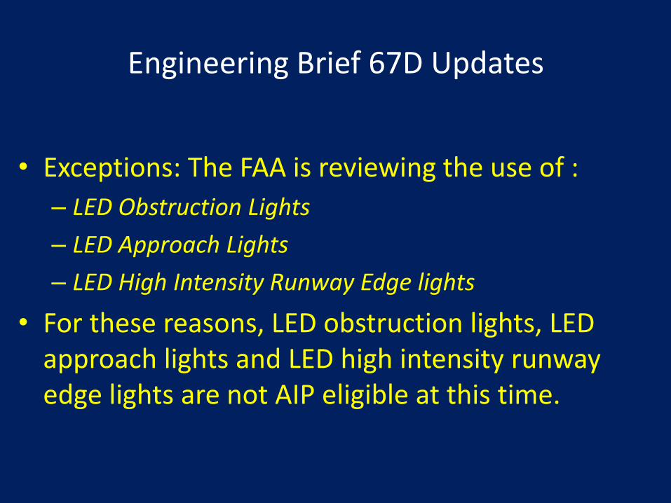
• Exceptions: The FAA is reviewing the use of :
– LED Obstruction Lights
– LED Approach Lights
– LED High Intensity Runway Edge lights
• For these reasons, LED obstruction lights, LED approach lights and LED high intensity runway edge lights are not AIP eligible at this time.
Engineering Brief 67D Updates

Obstruction Lighting Equipment

DRAFT AC 5345-43G
SPECIFICATION FOR OBSTRUCTION LIGHTING EQUIPMENT

DRAFT AC 5345-43G, PRINCIPAL CHANGES
• Para 3.3.3, Light Colors, is corrected to not state aviation red. The color for red obstruction light must be per ICAO Annex 14, Vol.1, App 1, Colours for Aeronautical Ground Lights. Reference to EB #67’s chromaticity is removed.
• Paragraph 3.3.14.4, Alternative Lighting Devices (ALD) Equipment, reference to Engineering Brief #67 is removed to avoid any confusion about warranty requirements.
– Minimum rated life of 2 years without maintenance or loss of light output below the minimum specified intensity.

• Para 3.4.1.1, the Blondel-Rey-Douglas formula is updated to correct form per Yoshi Ohno at the National Institute of Standards and Technology (NIST).
• Paragraph 3.4.1.1d, add statement that multiple pulse flashes cannot be used in day or twilight applications.
DRAFT AC 5345-43G, PRINCIPAL CHANGES

The effective intensity for multiple pulse flashes as used in lights during nighttime operation must be calculated by (Blondel-Rey-Douglas equation). Multiple pulse flashes cannot be used in day or twilight applications.
DRAFT AC 5345-43G, PRINCIPAL CHANGES

DRAFT AC 5345-43G
• Table 1, 2, and 3 – change Peak Intensity (candela) to Effective Intensity (candela)
• Paragraph 3.4.1.5, L-864 Light Unit, add a requirement for multiple light units.
• Paragraph 4.2.10, System Operational Test – add a note about excluding Type L-810 lights from the requirements paragraphs 4.2.10c through f.
• EB 67D does not apply to this AC; only arctic kit*
• Flashing L-810*…is coming!

Obstruction Lighting/Wildlife R&D Project
• In 2009 at the request of the Obstruction Evaluation Services Team (AT), Airport Engineering Division (AAS-100) asked the Airport Safety Technology Team to conduct a research project that includes the following requirements:

• Evaluate the concept of either omitting or flashing the normally steady burning red lights;
• Evaluate differences in the conspicuity of flashing vs. steady burning obstruction lights; and
• Evaluating the benefits of using new light emitting diode (LED) obstruction lights over conventional incandescent obstruction lights.
Obstruction Lighting/Wildlife R&D Project

• There are several factors involved in this issue: – Migratory birds love obstruction lighting – Wildlife research studies pointing at steady burning
lights (L-810s) as problem. – Wildlife organizations, the telecommunication
industry, and the FCC collectively approached the FAA and requested that the FAA consider re-defining the standards for obstruction lighting to either omit or flash the normally steady burning red lights to reduce their impact on the mortality rates of migratory birds
– Increased construction of communication towers and wind turbines.
– AC 70/7460-1K needs updated.
Contributing Factors: Flashing vs. Steady

Proposed Change To AC 7460-1K
• FAA Lighting Style A
• Size “A0” – No change.
• Size “A1” – No change, but offer option to flash L-810 and L-864 together simultaneously.
• Size “A2 thru A5” – Omit
L-810s, L-864s continue to
flash in unison.

• Draft Engineering Brief – “Aviation Obstruction and Ground Lighting Visibility with Night Vision (NVIS) Systems” – Provides information about the interaction
of light emitting diodes (LEDs) used for both obstruction and aviation ground lighting with night vision systems on board both rotary and fixed wing aircraft.
Obstruction Lighting Equipment

Light Fixture Performance Criteria

Light Fixture Performance Criteria
• 2.5 Light Fixture Performance Criteria - Manufacturers are required to publish the performance criteria for all light generating devices.
• This performance criteria is defined as worst-case wattage and VA at both the input leads of the fixture and, for fixtures powered from a series circuit, across the primary winding of an appropriately sized isolation transformer.

Light Fixture Performance Criteria
• The fixture lead length shall not exceed 24 inches for this test. This information shall be listed on the manufacturer's datasheets and verified by third party certification body.
• The manufacturer shall also state the operational current range, for series circuit powered fixtures, or input voltage range, for voltage powered fixtures, on their datasheets and verified by the third party certification body test laboratory.

• What is the motivation for requiring this testing?
• Achieving a good Power Factor(pf)!
Light Fixture Performance Criteria
Intensity of a Fixture With Alternative Lighting Source
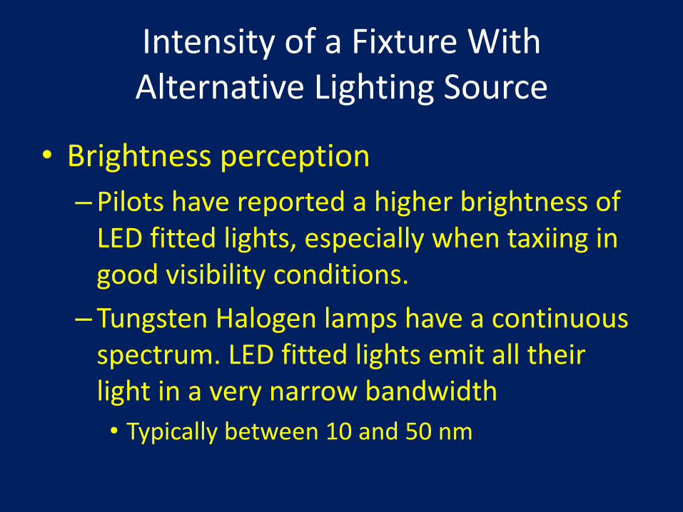
• Brightness perception
– Pilots have reported a higher brightness of LED fitted lights, especially when taxiing in good visibility conditions.
– Tungsten Halogen lamps have a continuous spectrum. LED fitted lights emit all their light in a very narrow bandwidth
• Typically between 10 and 50 nm
Intensity of a Fixture With Alternative Lighting Source

• Light Emitting Diodes (LED)
– Standard Incandescent lights have been around for over 60 years.
– LEDs while not new, have finally achieved intensity levels to be considered for use on airports.
– NOT just another “light bulb” that can plug and play!
Intensity of a Fixture With Alternative Lighting Source

• The eye is very sensitive to contrast.
– The higher the contrast is the higher the brightness perception (good visibility).
• There is a quantifiable “brightness/luminance” ratio.
– The conversion factor equals
– 1.4 for blue and green
– 1.6 for white
Intensity of a Fixture With Alternative Lighting Source

• However, light scattered by Fog can desaturate LED signal colors reducing or eliminating the brightness advantage.
Intensity of a Fixture With Alternative Lighting Source

Chromaticity – Fixture Daytime Viewing

• A means must be provided on all L-860E, L-861T, L-861E, L861SE and L-862E elevated airport to indicate specified light color during daytime viewing.
• Defined chromaticity boundaries for LEDs per EB-67D
Chromaticity – Fixture Daytime Viewing

LED L-861T Taxiway Edge
• Original LED Taxiway Edge Light
– Transparent light filter
– Small surface area for color blue to denote type if fixture

LED L-861T Taxiway Edge
• Present LED Taxiway Edge Light
– Standard globe
– Larger surface area for color blue

Innovative and Energy-Saving Product Utilizing LED Light Source

Electrical Infrastructure Research Team (EIRT)
A team of FAA and Industry experts formed to design an Airport Lighting Infrastructure to take full advantage of new lighting technologies.

Goals
• A system that promotes interoperability.
• Reduced life cycle cost without dependence upon a single source.
• A standards-based, robust architecture airfield lighting system.
Electrical Infrastructure Research Team (EIRT)

• Circuits considered:
– 450 V, AC Parallel Circuit
– 2 Amp, DC Series Circuit
– 2.8 Amp, AC Series Circuit
– AC Series Circuit w/ Control and Monitoring
• Currently conducting small scale circuit testing
Innovative and Energy-Saving Product Utilizing LED Light Source

Electrical Infrastructure Research Team (EIRT)
• Currently developing the test criteria and metrics for testing these circuits.
• Once criteria established:
- Start conducting small scale testing at the William J. Hughes Technical Center.
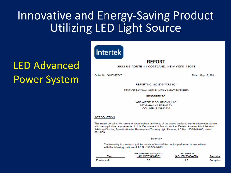
LED Advanced Power System
Innovative and Energy-Saving Product Utilizing LED Light Source

A Solution for an Airfield Lighting Architecture
that is Optimized for LED Technology
Advanced Power Supply System
94
Alternating PWM Power Supply for LEDs

95
• Minimum fixture complexity – Greater reliability, due to lower equipment
component part count – Further reduced energy consumption
(compared to 6.6A LED systems)
• Based on a series circuit
APS - What are the Primary Goals?

96
Solutions
6.6A LED Fixture Loading
Series Circuit
Isolation Transformer
LED Engine
Electronics
LED W
LED W + Electronics VA (Fixture Load)
CCR Load VA
L-861T: 1W
L-861T: 12VA 11VA for Electronics
L-861T: 15VA for 10/15W XF 3VA for XF L-861T: 21VA for 30/45W XF 9VA for XF
For Elevated Taxiway Edge light, non-LED electrical load is 93% to 95% of the total load

97
APS
Shorting Device
Isolation Transformer
Isolation Transformer
Shorting Device
1KW or 2KW 3 or 5-Step
Input: 240 VAC, 60 Hz 230 VAC, 50 Hz
APS Elevated Fixture
APS In-pavement Fixture
Output: 2A Max Alternating PWM
Remote Control/ Fault Monitoring
Standard L-824 AWG 8 or AWG 6, 5KV
Isolation Transformer and Shorting Device:
• Transformer isolates the fixture from the series circuit, insuring there is a low voltage on the fixture input terminals
• Bypasses the Alternating PWM current in case an elevated fixture is knocked over
APS Architecture

APS Output is Pulse Width Modulated in
Order to Communicate Intensity Level
• PWM: Vary width of ON time, but (when ON) current is at nominal level
2 Amps
Zero
2 Amps
Zero
2 Amps
Zero
Med Intensity
High Intensity
Low Intensity
99
APS- Benefits
• Decreased overall system complexity (i.e. greater reliability)
• Uses lower operating voltages (safety)
• Increase savings on energy costs due to reduction in:
– Fixture losses
– Series Circuit wire line loss
– Power Supply losses

APS Installation Benefit
100
9.06” H x 19.00” W x 20.10” D
Up to 5 APS in a single Cabinet
(2 x Runway, 2 x Taxiway, 1 Spare)
Space Savings

101
APS- Airfield Fixture Availability
• Elevated Taxiway Edge Light
• In-pavement Taxiway Edge Light
• In-pavement Taxiway Centerline Light
• Obstruction Light
• Medium Intensity Elevated Runway Edge Light
• Airfield Signs

102
• Atlanta, GA- Operational October 2006
– 1 circuit with 30 L-852T and nine L-810 fixtures
– 1 circuit with 60 L-852C fixtures
• RAF Mildenhall, UK- Operational May 2010
– 1 circuit with 62 ICAO Taxiway in-pavement edge fixtures
• Windsor, ON- Operational July 2010
– 1 circuit with 91 elevated taxiway edge fixtures
• Calgary, AB- Operational October 2010
– 1 circuits with 30 total elevated taxiway edge fixtures
• False River, LA- Operational May 2010
– Solar powered system
– 1 Circuit with 170 L-852T and 6 L-861T fixtures
• Niagara, ON- Operational June 2011
– 4 circuits with 60 total elevated medium intensity runway edge and 131 total elevated taxiway edge fixtures
Some APS Installation References

103
Louisiana Solar Powered Project
Battery
PV CHARGE CONTROLLER
- +
DC Load Battery PV
- + - +
Photovoltaic (PV) Panel
Vault Building
APS Powered LED Fixtures
Commercial Power/Backup Engine Generator
L-852T (Qty = 170)
L-861T (Qty = 6)
DC to AC
Inverter
APS
PWM
Control
Transfer
Switch
Inverter Operational Power
Inverter AC
Output
NEMA 4 Enclosure

Louisiana Solar Powered Project
104

APS Business Case
105
Traditional Circuit APS Circuit
Elevated Taxiway Fixtures 45 Watts 3.8W (LED)
Transformer Loss 9 Watts 0
Quantity 164 164 (In-pavement)
Circuit Length 18,000 feet 18,000
Circuit Power Loss 517 Watts 47.52 Watts
Total Circuit Load 8,906 Watt 670 Watts
CCR Size Required 15kW 1kW APS
False River Airport, Louisiana- Operational since May 2010
Energy Savings 93%

106
System Energy Use Comparison
Based on average energy use for 164 elevated taxiway edge fixtures (Data obtained from False River Regional Airport project)
Relative Energy
Cost
per
Year
6.6A Incandescent
6.6A LED
100
80
60
40
20
0 PWM
Series LED
100%
27.5%
7.0%

Atlanta International Airport
107
• (2) 1kW APS units
• Installed Oct 06. ATL installation of DC LED fixtures consists of 2 circuits: – 30 L-852T and 9 L-810 on Ramp 6N and along Taxiway F
– 60 L-852C on Taxiway D between Taxiway F and Ramp 6N

Denver International Airport
108
• (1) 2 KW APS
• (60) Taxiway C/L In-pavement fixtures

Niagara District, ON
109
Power on June 2011 4 circuits with 60 total elevated medium intensity runway edge and 131 total elevated taxiway edge fixtures

Questions?

• The method of computation is different. • The previous equation from the Edwards AFB Experiment: Notice that the values in the denominator are different than Yoshi Ohno's equation from NIST where: the sums of integrals are divided by the entire time from t1 to t2. The denominator of the Ohno equation: /a + (t2 - t1)
DRAFT AC 5345-43G, PRINCIPAL CHANGES

Power Factor Definition
• Power Factor = Cosine of phase angle between voltage and current.
• Power factor has no units.
• The value of PF ranges from 0 to 1.
• Loads that are only resistive (no capacitance or inductance) have a PF of 1.

• Fixture isolation ratio transformer outputs current needed by fixture LED(s)
113
APS Output- Alternating PWM
• Power Supply output alternates in order to pass through fixture isolation transformer
2 Amps
Zero Med Intensity
-2 Amps
180Hz
750 mA
-750 mA

Bridge Rectifier
+
-
Ratio Transformer*
* Ratio Transformer transforms 2A input into level needed for LED(s)
Surge Protection
Surge Protection
APS Fixture Implementation
114

115
Solutions
Alternating PWM
• After passing through ratio transformer, current to LED(s) are converted to all positive cycles by the Bridge Rectifier
750mA
Zero Med Intensity
360Hz