AirPave Guide - American Concrete Pavement …acpa.org/AirPave/AirPaveUserManual.pdf · Modulus of...
44
AirPave Guide AirPave11 (SW01)
-
Upload
duonghuong -
Category
Documents
-
view
220 -
download
0
Transcript of AirPave Guide - American Concrete Pavement …acpa.org/AirPave/AirPaveUserManual.pdf · Modulus of...
AirPave Guide
AirPave11 (SW01)
AirPave Guide
This publication is intended SOLELY for use by PROFESSIONAL PERSONNEL who are competent to evaluate the significance and limitations of the information provided herein, and who will accept total responsibility for the application of this information. The American Concrete Pavement Association DISCLAIMS any and all RESPONSIBILITY and LIABILITY for the accuracy of and the application of the information contained in this publication to the full extent permitted by law.
All rights reserved. No part of this book may be reproduced in any form without permission in writing from the publisher, except by a reviewer who wishes to quote brief passages in a review written for inclusion in a magazine or newspaper.
© 2011 American Concrete Pavement Association
ACPA is the premier national association representing concrete pavement contractors, cement companies, equipment and materials manufacturers and suppliers. We are organized to address common needs, solve other problems, and accomplish goals related to research, promotion, and advancing best practices for design and construction of concrete pavements.
3
Table of Contents
About ACPA’s AirPave ................................................................................................................................... 5
Using AirPave ................................................................................................................................................ 5
Installation ................................................................................................................................................ 5
The AirPave Software Interface ................................................................................................................ 5
Airport Pavement Evaluation Option Buttons ...................................................................................... 5
General Project Information ................................................................................................................. 6
Analysis Type ......................................................................................................................................... 7
Operation Guide Window ..................................................................................................................... 7
User Defined Input ................................................................................................................................ 8
Operation Command Buttons ............................................................................................................. 11
Exiting the AirPave Software................................................................................................................... 12
Uninstalling the AirPave Software .......................................................................................................... 12
Technical Background ................................................................................................................................. 13
Introduction ............................................................................................................................................ 13
Program Basics ........................................................................................................................................ 13
Program Scope ........................................................................................................................................ 14
Definitions of Terms ................................................................................................................................ 16
Calculation Method for Stress Maximization ......................................................................................... 18
Edge Stresses vs. Interior Stresses .......................................................................................................... 20
Concrete Strength and Elasticity Properties ........................................................................................... 21
Subbase/Subgrade Support Strength ..................................................................................................... 22
Limitations on Input Values .................................................................................................................... 23
Radius of Relative Stiffness ..................................................................................................................... 26
Coordinates of Wheels ............................................................................................................................ 27
The Airport Pavement Thickness Design Process using AirPave............................................................. 28
Selection of Allowable Pavement Stress ............................................................................................. 29
Design/Evaluation Examples ............................................................................................................... 30
References .................................................................................................................................................. 41

4
This Page Left Intentionally Blank
5
About ACPA’s AirPave ACPA’s AirPave software is a Windows-based computer program, developed by Construction Technology Laboratories, Inc. (CTL) under the sponsorship of ACPA, for valuation of airport concrete pavements subjected to aircraft traffic. This software is based on the “AIRPORT” computer program, originally developed by Mr. Robert G. Packard of the Portland Cement Association (PCA), for mainframe computers and later converted to microcomputers by Roger Millikan. This manual is based on the manuals prepared by Mr. Packard for the original and the updated programs.
Using AirPave AirPave is designed to be intuitive and user friendly with clearly captioned option buttons, command buttons, input boxes, and other operational tools.
Installation To install AirPave:
1. Insert the AirPave CD-ROM disk into the CD-ROM disk drive; 2. If the setup screen pops up, follow the instructions on the screen; 3. If the setup screen does not pop up, run the “Setup” executable file on the CD-
ROM disk and follow the instructions on the screen. The AirPave software can alternatively be downloaded from ACPA’s website at: http://acpa.org/airpave/
The AirPave Software Interface
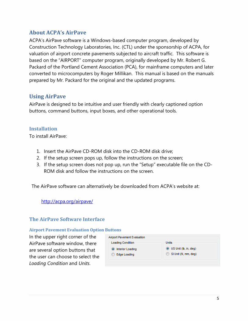
Airport Pavement Evaluation Option Buttons
In the upper right corner of the AirPave software window, there are several option buttons that the user can choose to select the Loading Condition and Units.
6
Loading Condition – This allows the users to perform pavement evaluation under either interior loading or edge loading. Loads are applied on a slab away from edges or joints when interior loading is selected. When the edge loading is selected, loads are applied along the edge of a slab. See the relevant discussions later in this document to understand the difference between the interior loading and edge loading conditions and the appropriateness of when to use each option. Units – AirPave can work in either U.S. American Customary units or SI units.
· With U.S. units: o Thickness of the pavement slab is inches (in.) o Contact area is in square inches (in2) o Tire pressure, concrete strength (MR), and stresses are in pound per square
inch (psi) o Subbase/subgrade modulus of reaction (k) is in pound per cubic inch (pci) o Modulus of elasticity of the concrete (E) is in million psi
· With SI units:
o Thickness of the pavement slab is centimeters (cm) o Contact area is in square centimeters (cm2) o Tire pressure, concrete strength (MR), and stresses are in kilopascals (kPa) o Subbase/subgrade modulus of reaction (k) is in megapascals per meter
(MPa/m) o Modulus of elasticity of the concrete (E) is in megapascals (MPa)
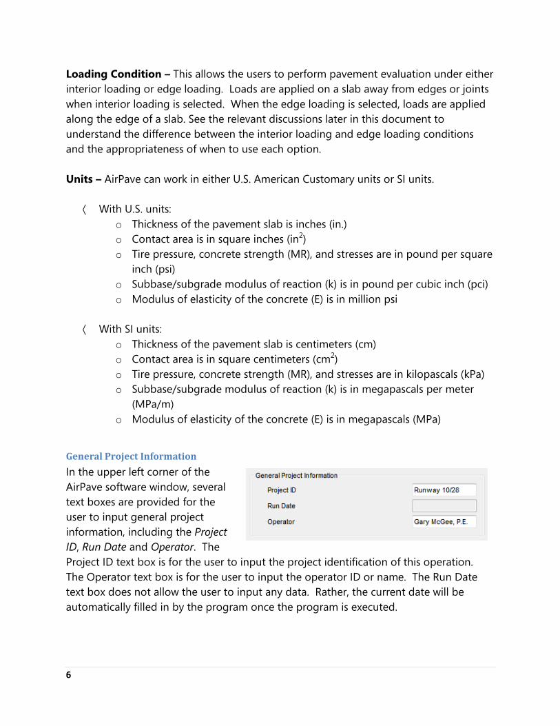
General Project Information
In the upper left corner of the AirPave software window, several text boxes are provided for the user to input general project information, including the Project ID, Run Date and Operator. The Project ID text box is for the user to input the project identification of this operation. The Operator text box is for the user to input the operator ID or name. The Run Date text box does not allow the user to input any data. Rather, the current date will be automatically filled in by the program once the program is executed.
7
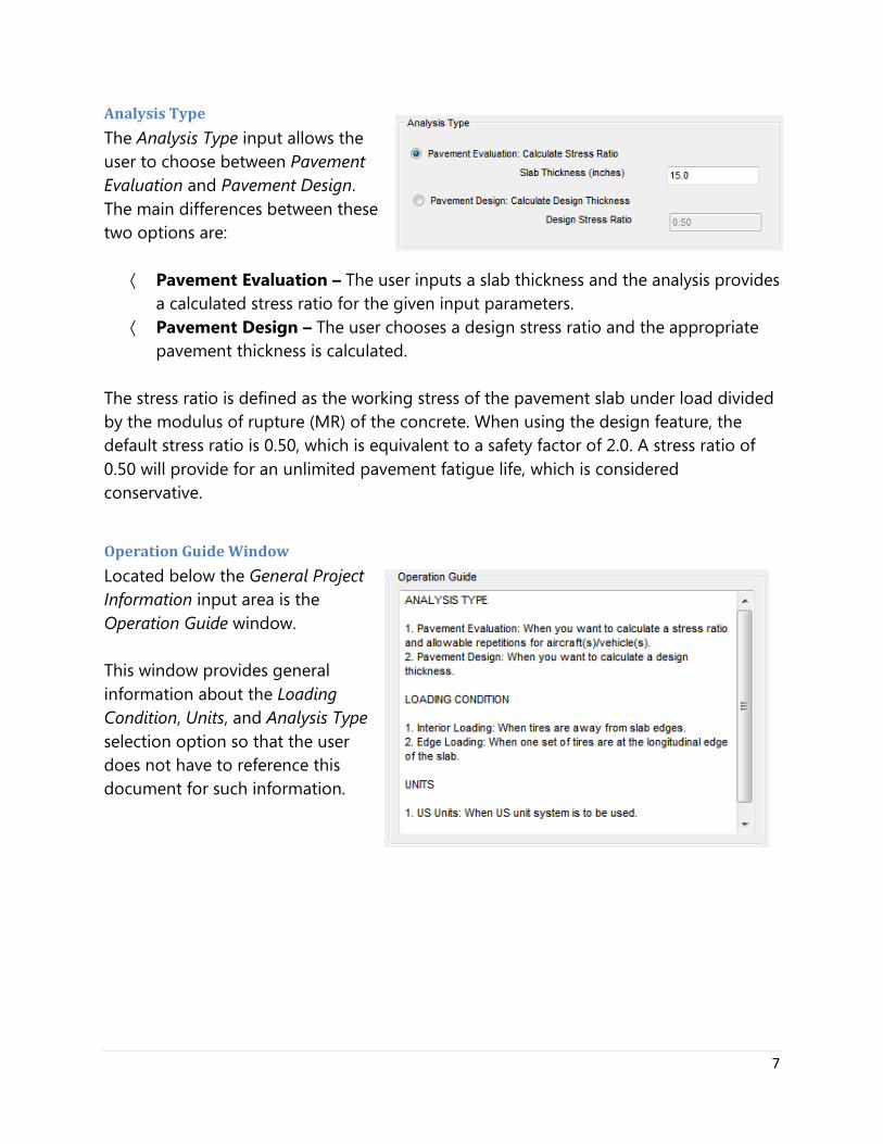
Analysis Type
The Analysis Type input allows the user to choose between Pavement Evaluation and Pavement Design. The main differences between these two options are:
· Pavement Evaluation – The user inputs a slab thickness and the analysis provides a calculated stress ratio for the given input parameters.
· Pavement Design – The user chooses a design stress ratio and the appropriate pavement thickness is calculated.
The stress ratio is defined as the working stress of the pavement slab under load divided by the modulus of rupture (MR) of the concrete. When using the design feature, the default stress ratio is 0.50, which is equivalent to a safety factor of 2.0. A stress ratio of 0.50 will provide for an unlimited pavement fatigue life, which is considered conservative.
Operation Guide Window
Located below the General Project Information input area is the Operation Guide window. This window provides general information about the Loading Condition, Units, and Analysis Type selection option so that the user does not have to reference this document for such information.
8
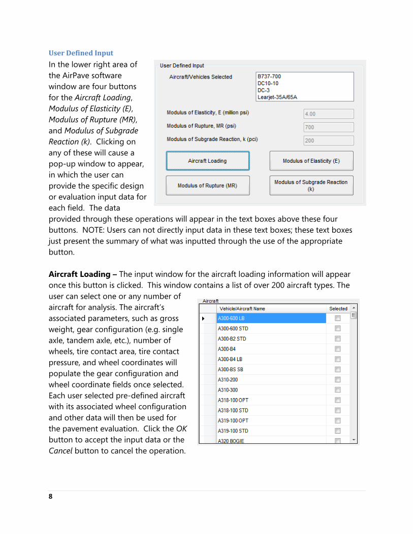
User Defined Input
In the lower right area of the AirPave software window are four buttons for the Aircraft Loading, Modulus of Elasticity (E), Modulus of Rupture (MR), and Modulus of Subgrade Reaction (k). Clicking on any of these will cause a pop-up window to appear, in which the user can provide the specific design or evaluation input data for each field. The data provided through these operations will appear in the text boxes above these four buttons. NOTE: Users can not directly input data in these text boxes; these text boxes just present the summary of what was inputted through the use of the appropriate button. Aircraft Loading – The input window for the aircraft loading information will appear once this button is clicked. This window contains a list of over 200 aircraft types. The user can select one or any number of aircraft for analysis. The aircraft’s associated parameters, such as gross weight, gear configuration (e.g. single axle, tandem axle, etc.), number of wheels, tire contact area, tire contact pressure, and wheel coordinates will populate the gear configuration and wheel coordinate fields once selected. Each user selected pre-defined aircraft with its associated wheel configuration and other data will then be used for the pavement evaluation. Click the OK button to accept the input data or the Cancel button to cancel the operation.
9
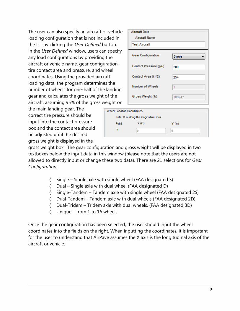
The user can also specify an aircraft or vehicle loading configuration that is not included in the list by clicking the User Defined button. In the User Defined window, users can specify any load configurations by providing the aircraft or vehicle name, gear configuration, tire contact area and pressure, and wheel coordinates. Using the provided aircraft loading data, the program determines the number of wheels for one-half of the landing gear and calculates the gross weight of the aircraft, assuming 95% of the gross weight on the main landing gear. The correct tire pressure should be input into the contact pressure box and the contact area should be adjusted until the desired gross weight is displayed in the gross weight box. The gear configuration and gross weight will be displayed in two textboxes below the input data in this window (please note that the users are not allowed to directly input or change these two data). There are 21 selections for Gear Configuration:
· Single – Single axle with single wheel (FAA designated S) · Dual – Single axle with dual wheel (FAA designated D) · Single-Tandem – Tandem axle with single wheel (FAA designated 2S) · Dual-Tandem – Tandem axle with dual wheels (FAA designated 2D) · Dual-Tridem – Tridem axle with dual wheels. (FAA designated 3D) · Unique – from 1 to 16 wheels
Once the gear configuration has been selected, the user should input the wheel coordinates into the fields on the right. When inputting the coordinates, it is important for the user to understand that AirPave assumes the X axis is the longitudinal axis of the aircraft or vehicle.
10
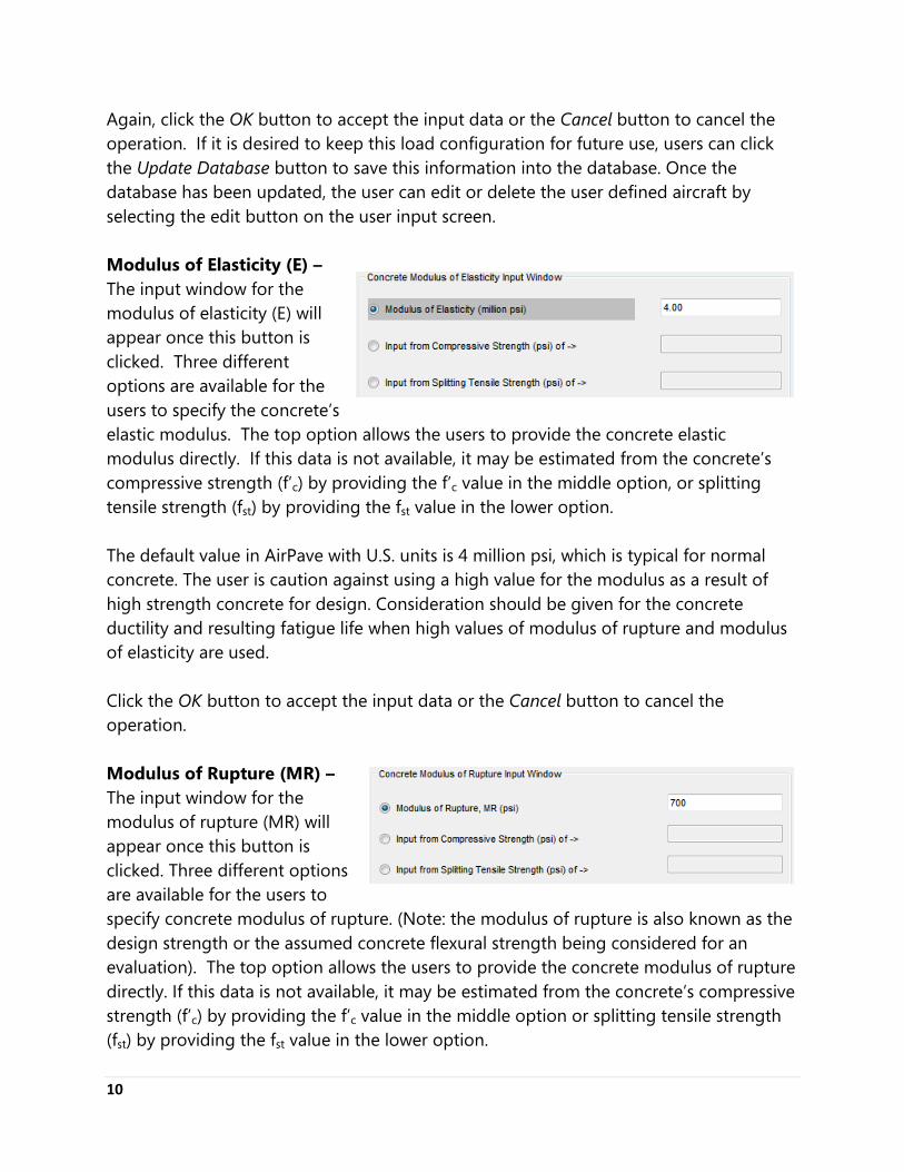
Again, click the OK button to accept the input data or the Cancel button to cancel the operation. If it is desired to keep this load configuration for future use, users can click the Update Database button to save this information into the database. Once the database has been updated, the user can edit or delete the user defined aircraft by selecting the edit button on the user input screen. Modulus of Elasticity (E) – The input window for the modulus of elasticity (E) will appear once this button is clicked. Three different options are available for the users to specify the concrete’s elastic modulus. The top option allows the users to provide the concrete elastic modulus directly. If this data is not available, it may be estimated from the concrete’s compressive strength (f’c) by providing the f’c value in the middle option, or splitting tensile strength (fst) by providing the fst value in the lower option. The default value in AirPave with U.S. units is 4 million psi, which is typical for normal concrete. The user is caution against using a high value for the modulus as a result of high strength concrete for design. Consideration should be given for the concrete ductility and resulting fatigue life when high values of modulus of rupture and modulus of elasticity are used. Click the OK button to accept the input data or the Cancel button to cancel the operation. Modulus of Rupture (MR) – The input window for the modulus of rupture (MR) will appear once this button is clicked. Three different options are available for the users to specify concrete modulus of rupture. (Note: the modulus of rupture is also known as the design strength or the assumed concrete flexural strength being considered for an evaluation). The top option allows the users to provide the concrete modulus of rupture directly. If this data is not available, it may be estimated from the concrete’s compressive strength (f’c) by providing the f’c value in the middle option or splitting tensile strength (fst) by providing the fst value in the lower option.
11
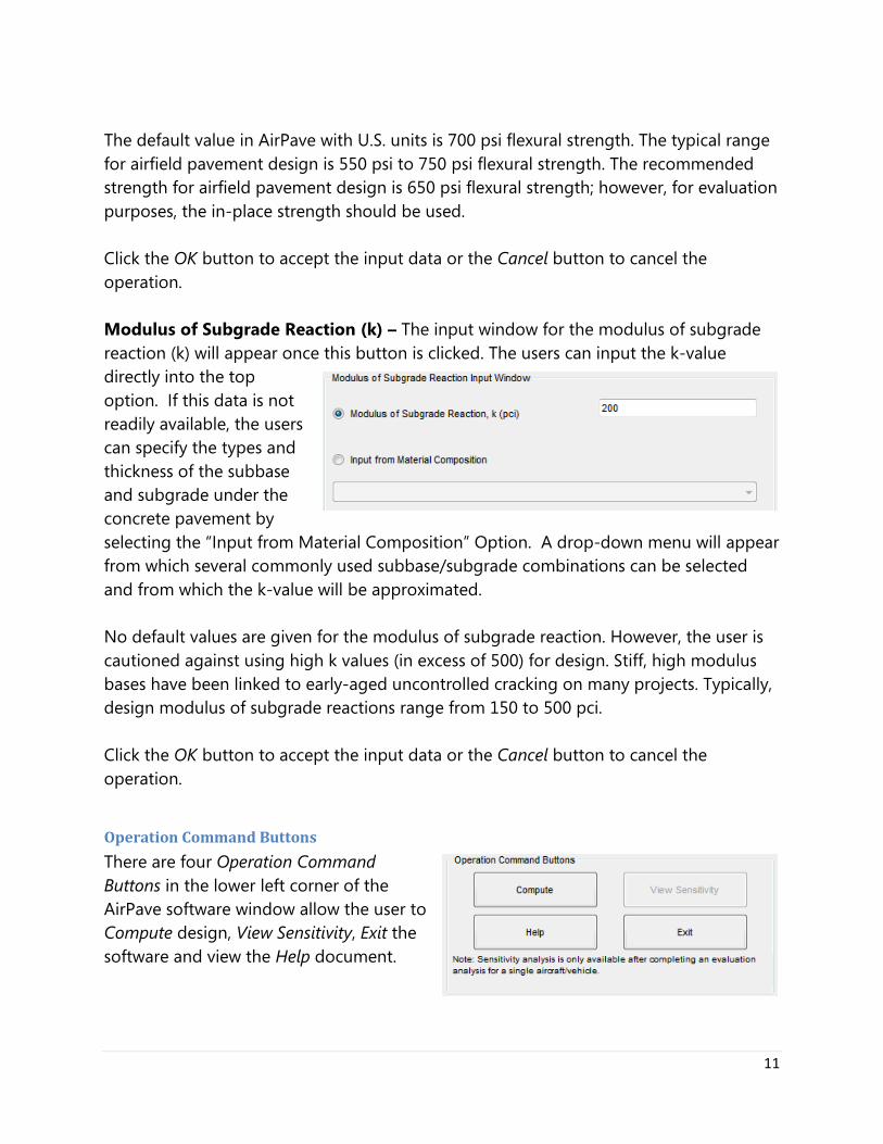
The default value in AirPave with U.S. units is 700 psi flexural strength. The typical range for airfield pavement design is 550 psi to 750 psi flexural strength. The recommended strength for airfield pavement design is 650 psi flexural strength; however, for evaluation purposes, the in-place strength should be used. Click the OK button to accept the input data or the Cancel button to cancel the operation. Modulus of Subgrade Reaction (k) – The input window for the modulus of subgrade reaction (k) will appear once this button is clicked. The users can input the k-value directly into the top option. If this data is not readily available, the users can specify the types and thickness of the subbase and subgrade under the concrete pavement by selecting the “Input from Material Composition” Option. A drop-down menu will appear from which several commonly used subbase/subgrade combinations can be selected and from which the k-value will be approximated. No default values are given for the modulus of subgrade reaction. However, the user is cautioned against using high k values (in excess of 500) for design. Stiff, high modulus bases have been linked to early-aged uncontrolled cracking on many projects. Typically, design modulus of subgrade reactions range from 150 to 500 pci. Click the OK button to accept the input data or the Cancel button to cancel the operation.
Operation Command Buttons
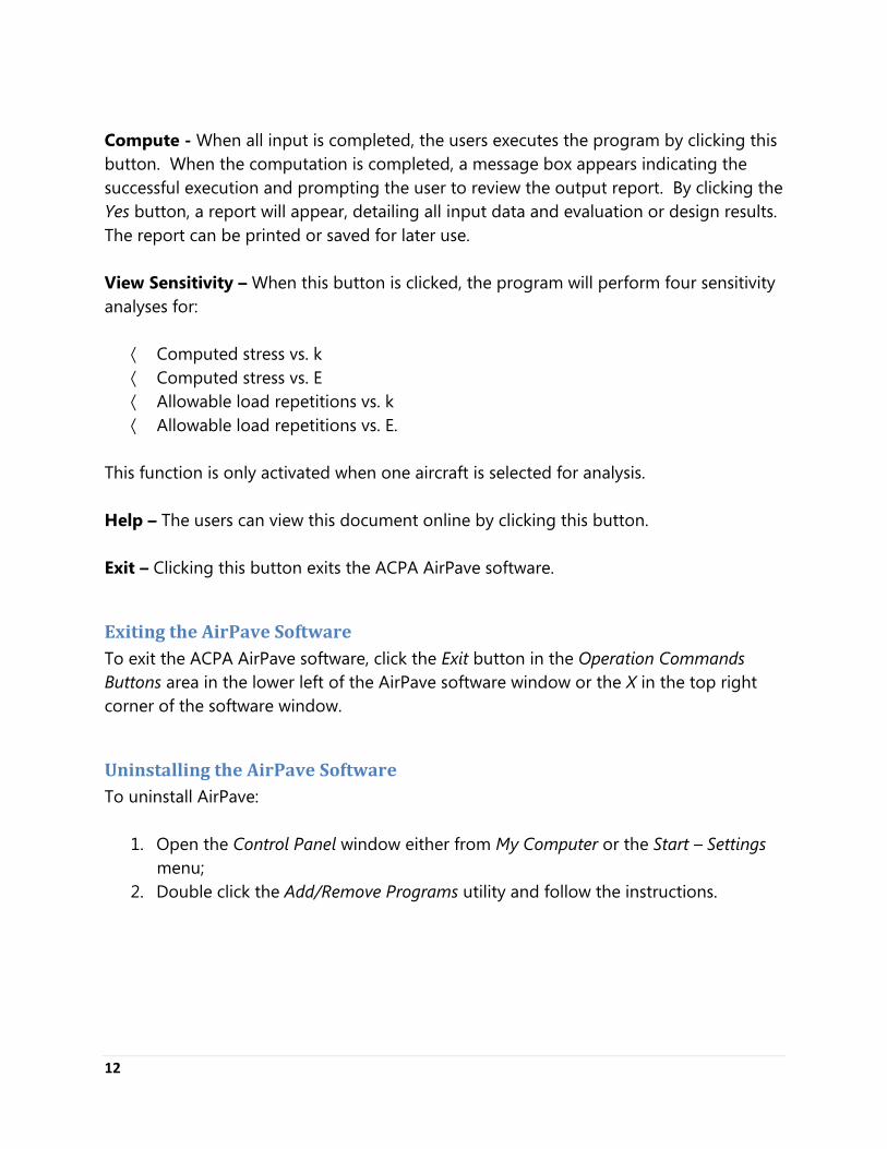
There are four Operation Command Buttons in the lower left corner of the AirPave software window allow the user to Compute design, View Sensitivity, Exit the software and view the Help document.
12
Compute - When all input is completed, the users executes the program by clicking this button. When the computation is completed, a message box appears indicating the successful execution and prompting the user to review the output report. By clicking the Yes button, a report will appear, detailing all input data and evaluation or design results. The report can be printed or saved for later use. View Sensitivity – When this button is clicked, the program will perform four sensitivity analyses for:
· Computed stress vs. k · Computed stress vs. E · Allowable load repetitions vs. k · Allowable load repetitions vs. E.
This function is only activated when one aircraft is selected for analysis. Help – The users can view this document online by clicking this button. Exit – Clicking this button exits the ACPA AirPave software.
Exiting the AirPave Software To exit the ACPA AirPave software, click the Exit button in the Operation Commands Buttons area in the lower left of the AirPave software window or the X in the top right corner of the software window.
Uninstalling the AirPave Software To uninstall AirPave:
1. Open the Control Panel window either from My Computer or the Start – Settings menu;
2. Double click the Add/Remove Programs utility and follow the instructions.
13
Technical Background
Introduction This Windows-based computer program determines the critical pavement bending stresses due to any configuration of wheel loads of aircraft or other vehicles such as industrial lift trucks, log handling equipment, straddle carriers, dump trucks, and other construction loading. However, the program may not be applicable for distributed loads covering vary large contact areas. The 2011 version of AirPave contains a comprehensive aircraft library consisting of most commercially manufactured aircraft. The user may create additional vehicle loading models by inputting wheel coordinates along with other loading data and storing those in the AirPave library. To use the program, the following data are required:
- Spacing of wheels (loads), - Gear configuration, - Load contact area, - Load contact pressure, - Strength of subgrade-subbase, - Concrete modulus of elasticity, and - Concrete flexural strength.
Although the program will accept wide ranges of input values, the user is caution against using extreme input values that are outside the realm of practical experience and good engineering judgment.
Program Basics This program is based on the Portland Cement Association’s (PCA) AIRPORT computer program [2, 3], originally developed by Mr. Robert Packard in 1967. The analysis procedure used in the AIRPORT program is based on an extension by Pickett [4] of Westergaard’s analysis for loads at the interior of a slab supported by a dense liquid subgrade. Influence Chart No. 2 of Pickett and Ray [5] has been used as a graphical solution to the analysis.
14
Program Scope In the original version of the program, for a given user-inputted concrete pavement thickness, the program computed the flexural stress caused by the loads. If the computed stress was higher or lower than the user-selected criteria, the user re-ran the program with a greater or lesser pavement thickness. This iterative process would eventually lead to the user determining the minimum thickness necessary to keep the flexural stress caused by the loads below the limit they had deemed appropriate. This design method is still available by way of the Pavement Evaluation and it is still useful for situations where existing pavement (e.g., of a known thickness) is being evaluated; however, in this updated version of the software the user is also given an option to select multiple aircraft from the internal library and design the pavement to meet the user-defined allowable stress ratio, thus automating the design process. To illustrate a typical design using the new design process (e.g., Pavement Design option selected as the Analysis Type):
1. The user determines and inputs the Design Stress Ratio (e.g., ratio of load induced stress to concrete modulus of rupture) for their design. A common Design Stress Ratio is 0.50 because stress ratios of 0.50 or less do not induce any fatigue damage. A stress ratio of 0.50 corresponds to a Safety Factor of 2 (e.g., if stress ratio = stress/strength = 0.5, safety factor = strength/stress = 2). If, for example, the design concrete modulus of rupture is 700 psi and the design stress ratio is 0.5, the allowable maximum stress is 700*0.5 = 350 psi. Therefore, any aircraft that induces a stress of less than or equal to 350 psi for a given thickness and other design inputs will not induce any fatigue damage.
2. The user clicks the Aircraft Loading button and selects the aircraft(s) that are expected to use the pavement. For example, suppose the mixed fleet consists of B-737, B-757, and B-767 aircrafts. The user selects these three aircraft from the AirPave aircraft library.
3. The user then clicks on the Modulus of Rupture (MR) button and inputs the design modulus of rupture. For this example, assume the default of 700 psi.
4. Next, the user clicks on the Modulus of Elasticity E button and enters the design value; in this example the default value of 4 million psi is used.
5. Finally, the user clicks the Modulus of Subgrade Reaction (k) button and enters the design k-value. The k-value is the improved support modulus and it is dependent upon the type of subgrade/subbase material. For this example, assume the default value of 200 pci.
15
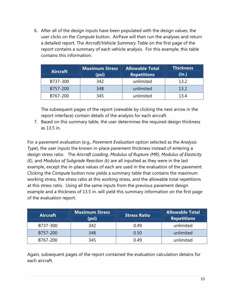
6. After all of the design inputs have been populated with the design values, the user clicks on the Compute button. AirPave will then run the analyses and return a detailed report. The Aircraft/Vehicle Summary Table on the first page of the report contains a summary of each vehicle analysis. For this example, this table contains this information:
Aircraft Maximum Stress
(psi) Allowable Total
Repetitions Thickness
(in.) B737-300 342 unlimited 13.2 B757-200 348 unlimited 13.2 B767-200 345 unlimited 13.4
The subsequent pages of the report (viewable by clicking the next arrow in the report interface) contain details of the analysis for each aircraft.
7. Based on this summary table, the user determines the required design thickness as 13.5 in.
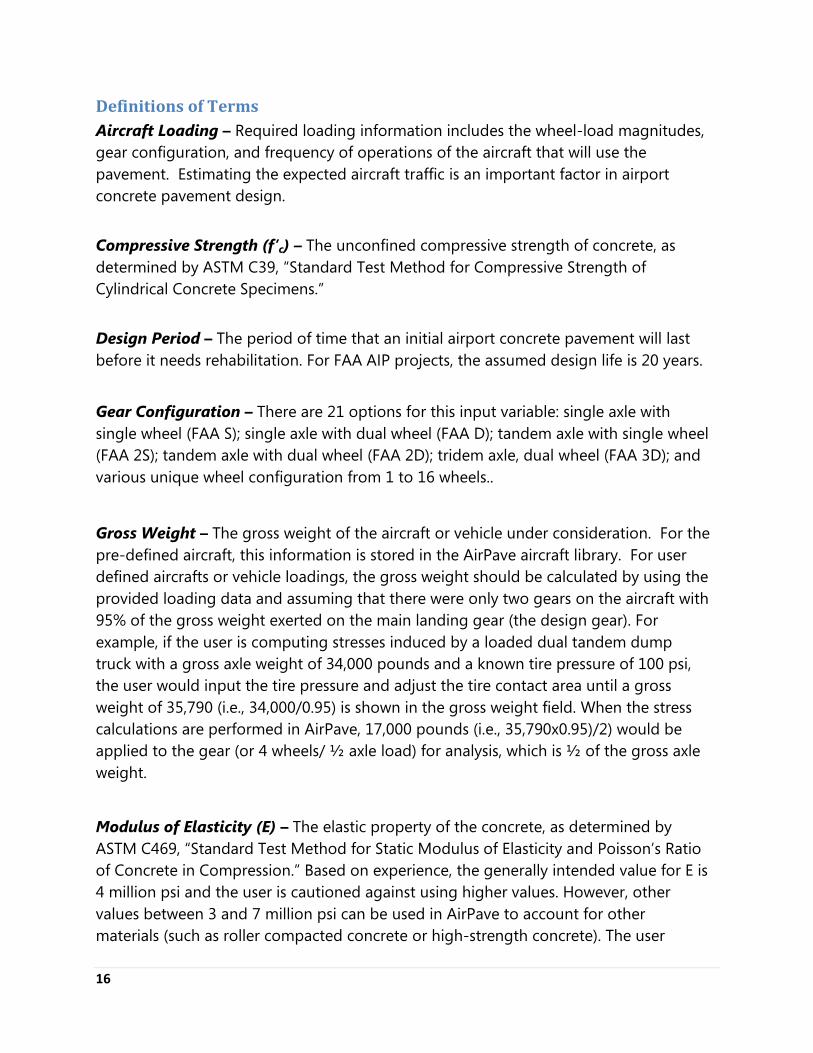
For a pavement evaluation (e.g., Pavement Evaluation option selected as the Analysis Type), the user inputs the known in-place pavement thickness instead of entering a design stress ratio. The Aircraft Loading, Modulus of Rupture (MR), Modulus of Elasticity (E), and Modulus of Subgrade Reaction (k) are all inputted as they were in the last example, except the in-place values of each are used in the evaluation of the pavement. Clicking the Compute button now yields a summary table that contains the maximum working stress, the stress ratio at this working stress, and the allowable total repetitions at this stress ratio. Using all the same inputs from the previous pavement design example and a thickness of 13.5 in. will yield this summary information on the first page of the evaluation report:
Aircraft Maximum Stress
(psi) Stress Ratio
Allowable Total Repetitions
B737-300 342 0.49 unlimited B757-200 348 0.50 unlimited B767-200 345 0.49 unlimited
Again, subsequent pages of the report contained the evaluation calculation detains for each aircraft.
16
Definitions of Terms Aircraft Loading – Required loading information includes the wheel-load magnitudes, gear configuration, and frequency of operations of the aircraft that will use the pavement. Estimating the expected aircraft traffic is an important factor in airport concrete pavement design. Compressive Strength (f’c) – The unconfined compressive strength of concrete, as determined by ASTM C39, “Standard Test Method for Compressive Strength of Cylindrical Concrete Specimens.” Design Period – The period of time that an initial airport concrete pavement will last before it needs rehabilitation. For FAA AIP projects, the assumed design life is 20 years.
Gear Configuration – There are 21 options for this input variable: single axle with single wheel (FAA S); single axle with dual wheel (FAA D); tandem axle with single wheel (FAA 2S); tandem axle with dual wheel (FAA 2D); tridem axle, dual wheel (FAA 3D); and various unique wheel configuration from 1 to 16 wheels..
Gross Weight – The gross weight of the aircraft or vehicle under consideration. For the pre-defined aircraft, this information is stored in the AirPave aircraft library. For user defined aircrafts or vehicle loadings, the gross weight should be calculated by using the provided loading data and assuming that there were only two gears on the aircraft with 95% of the gross weight exerted on the main landing gear (the design gear). For example, if the user is computing stresses induced by a loaded dual tandem dump truck with a gross axle weight of 34,000 pounds and a known tire pressure of 100 psi, the user would input the tire pressure and adjust the tire contact area until a gross weight of 35,790 (i.e., 34,000/0.95) is shown in the gross weight field. When the stress calculations are performed in AirPave, 17,000 pounds (i.e., 35,790x0.95)/2) would be applied to the gear (or 4 wheels/ ½ axle load) for analysis, which is ½ of the gross axle weight.
Modulus of Elasticity (E) – The elastic property of the concrete, as determined by ASTM C469, “Standard Test Method for Static Modulus of Elasticity and Poisson’s Ratio of Concrete in Compression.” Based on experience, the generally intended value for E is 4 million psi and the user is cautioned against using higher values. However, other values between 3 and 7 million psi can be used in AirPave to account for other materials (such as roller compacted concrete or high-strength concrete). The user
17
should understand the relationship between the modulus of elasticity and concrete strength and fracture/fatigue properties and use reasonable, compatible values. AirPave has conversion to E from compressive strength and splitting tensile strength built into the software; other conversions, such as one from flexural strength to E, are available in the free Strength Convertor app at http://apps.acpa.org. Also, for materials with E values of less than 3 million psi, such as lean concrete or soil cement, evidence suggest that these materials do not exhibit linear elastic theory. As such, the user is cautioned against using AirPave for thickness computations for these materials. Modulus of Rupture (MR) – The third point flexural strength of concrete, as determined by ASTM C78, “Standard Test Method for Flexural Strength of Concrete (Using Simple Beam with Third-Point Loading).” Unless construction conditions require opening pavement to traffic in less than 28 days, the 28-day strength is generally accepted as a construction acceptance criterion. However, the long-term concrete strength is generally at least 5 percent higher than the 28-day strength. For airport projects, the FAA recommends a design flexural strength between 600 and 700 psi for most applications. Lower design strengths allow for balancing the components of the concrete mixture. In general, this will result in slightly thicker pavements but it may reduce the risk of early-age uncontrolled cracking, minimize curling and warping stresses, and provide for a longer fatigue life. The user should consider these facts when selecting the pavement concrete modulus of rupture.
Number of Wheels – Number of wheels to be used in performing the evaluation. The maximum number of wheels that can be handled in this program is 16.
Splitting Tensile Strength (fst) – Can be determined using ASTM C496, “Standard Test Method for Splitting Tensile Strength of Cylindrical Concrete Specimens.” Tire Contact Area – The area of slab contact of each tire carrying the design aircraft wheel load. It may be estimated by dividing the wheel load by the tire inflation pressure. Tire manufactures generally provide information on maximum load at a desirable tire deflection, inflation pressure, and contact area. For design, the contact pressure is assumed to equal the wheel load divided by the contact area. A further assumption is that a different inflation pressure is specified for a change in design load so that the original tire deflection and contact area are maintained. However, for design using AirPave, it is sometimes convenient to adjust the contact area and maintain the tire pressure to adjust for a modified version of a particular aircraft or special vehicle. Computer analyses have shown that the stress level is not particularly
18
sensitive to changes in contact area. A stress change of less that 5 percent is typical for a wide variance of contact area. Tire Pressure – The tire inflation pressure, which can be obtained from the tire or equipment manufacturer. Tire pressures of the commercially manufactured aircraft are stored in the internal AirPave aircraft library. Total Design Load Applications – The total number of load applications the pavement will carry during the entire Design Period. That is to say, the number of load cycles, taking aircraft wander into consideration. It takes multiple passes of an aircraft to equal one load cycle in most cases. Refer to FAA Advisory Circular150/5320-6E. Modulus of Subgrade Reaction (k) – This represents the support condition under the concrete slabs, provided by subgrade and any subbase(s). The actual k-value can be determined by ASTM D1196, “Standard Test Method for Non-repetitive Static Plate Load Tests of Soils and Flexible Pavement Components for Use in Evaluation and Design of Airports and Highway Pavements.” The AirPave model is a two-layer system so the k-value is the actual improved modulus (e.g., subgrade plus any unstabilized or stabilized subbase(s)) at the interface between the subbase and the concrete surface course. A free k-value Calculator app is available at http://apps.acpa.org.
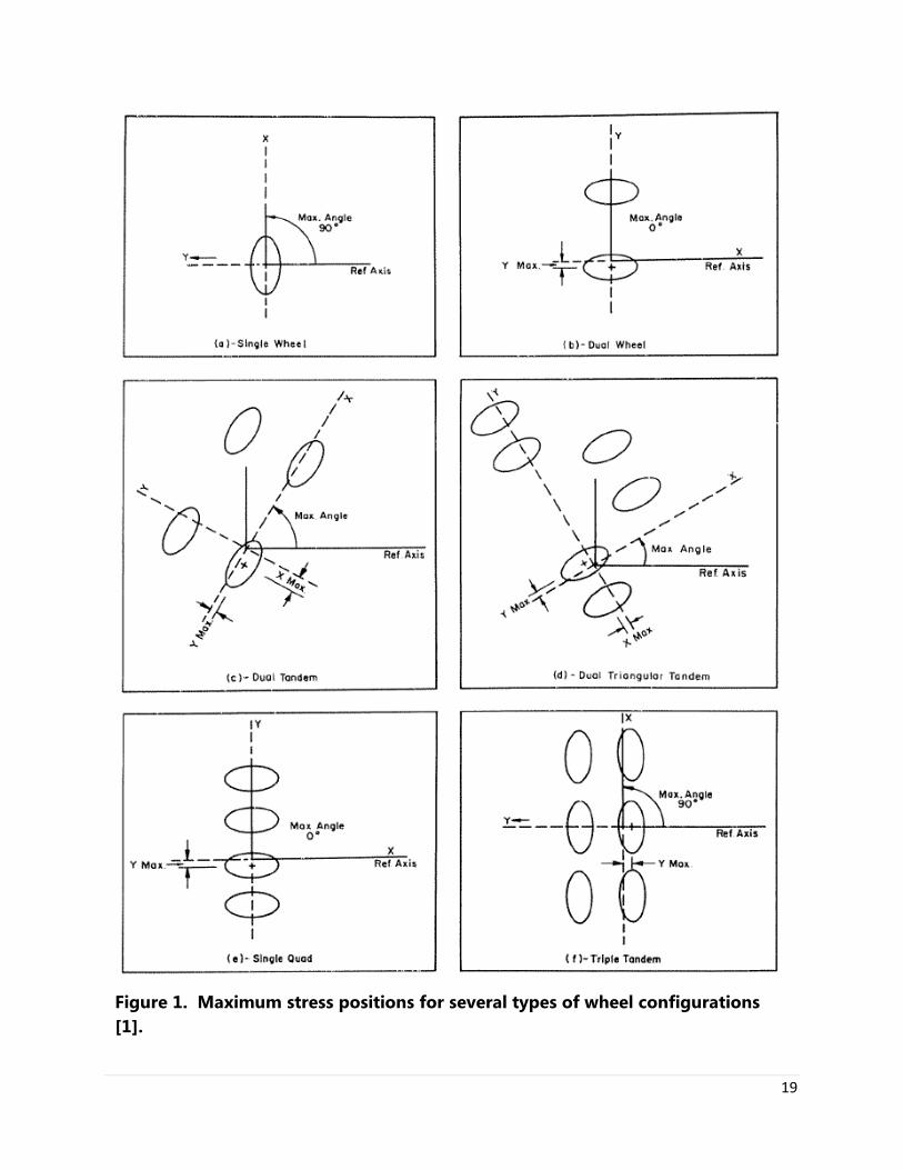
Calculation Method for Stress Maximization To calculate the maximum stress, AirPave rotates and shifts the design loading(s) (e.g., each wheel configuration considered) in the X-Y plane to determine the maximum load-induced stress (see Reference 3 for details). Three parameters are used to represent the shifting and rotating done by the program; these parameters are: XMAX, YMAX, and Maximum Angle (see Figure 1 for a graphical representation of these parameters for several wheel configurations). To indicate the location and direction of maximum stresses, the results are reported superficially as if the wheel configuration has been shifted and rotated. XMAX and YMAX – Represent the shift of the gear from an assumed original position; that is, the longitudinal axis of the aircraft in the direction of the reference axis. The dimensions of XMAX and YMAX are inches (cm if SI units are used).
19
Figure 1. Maximum stress positions for several types of wheel configurations [1].
20
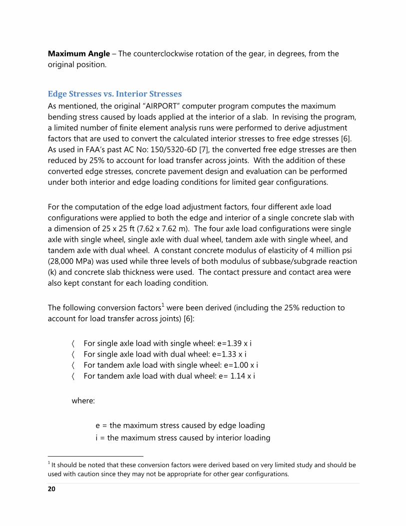
Maximum Angle – The counterclockwise rotation of the gear, in degrees, from the original position.
Edge Stresses vs. Interior Stresses As mentioned, the original “AIRPORT” computer program computes the maximum bending stress caused by loads applied at the interior of a slab. In revising the program, a limited number of finite element analysis runs were performed to derive adjustment factors that are used to convert the calculated interior stresses to free edge stresses [6]. As used in FAA’s past AC No: 150/5320-6D [7], the converted free edge stresses are then reduced by 25% to account for load transfer across joints. With the addition of these converted edge stresses, concrete pavement design and evaluation can be performed under both interior and edge loading conditions for limited gear configurations. For the computation of the edge load adjustment factors, four different axle load configurations were applied to both the edge and interior of a single concrete slab with a dimension of 25 x 25 ft (7.62 x 7.62 m). The four axle load configurations were single axle with single wheel, single axle with dual wheel, tandem axle with single wheel, and tandem axle with dual wheel. A constant concrete modulus of elasticity of 4 million psi (28,000 MPa) was used while three levels of both modulus of subbase/subgrade reaction (k) and concrete slab thickness were used. The contact pressure and contact area were also kept constant for each loading condition. The following conversion factors1
were been derived (including the 25% reduction to account for load transfer across joints) [6]:
· For single axle load with single wheel: e=1.39 x i · For single axle load with dual wheel: e=1.33 x i · For tandem axle load with single wheel: e=1.00 x i · For tandem axle load with dual wheel: e= 1.14 x i
where: e = the maximum stress caused by edge loading i = the maximum stress caused by interior loading
1 It should be noted that these conversion factors were derived based on very limited study and should be used with caution since they may not be appropriate for other gear configurations.
21
As a general guideline, when loads are placed father than 2l (e.g., two times the radius of relative stiffness) away from the pavement edge, they are considered as interior loading. A load is regarded as an edge loading when it is applied at 1l or closer to pavement edge.
Concrete Strength and Elasticity Properties Concrete material properties that are required to conduct designs or evaluations using AirPave include the Modulus of Rupture (MR) and Modulus of Elasticity (E). Values of these two variables may be directly input by the user, or they can be derived from other concrete strengths, including compressive strength and splitting tensile strength, which may be more readily available. The following U.S. unit conversion equations are used in AirPave:
· Modulus of Rupture (MR):
o From compressive strength: MR = 9 x (f’c)½ [5] o From splitting tensile strength: MR = 1.02 x (fst +200) [7]
· Modulus of Elasticity (E):
o From compressive strength: E = 57,000 x (f’c)½ [5] o From splitting tensile strength (two-step process):
f’c = 12.53 x fst – 1275 [8] Ec = 57,000 x (f’c)½ [5]
where all strengths and moduli are in pounds per square in. (psi). The free Strength Converter app at http://apps.acpa.org also conducts these and other conversions. ACPA recommends using the 90-day modulus of rupture as the design value; however, users may use 28-day data or other values when appropriate. In general, the design modulus of rupture should be what is expected or needed when the pavement is opened to traffic. Consideration should also be given to construction loading.
22
Subbase/Subgrade Support Strength The Modulus of Subgrade Reaction (k) is a measure of the overall support strength of the pavement system (e.g., the subgrade and any subbase(s)) and is a required input for conducting a concrete pavement design or evaluation with AirPave. This value can be input directly by the user in AirPave or the user can select an approximate k-value from different common combinations of types and thicknesses of subbase and/or subgrade. The available common values, derived from References 7 and 9, are:
· Fine-grained soil:
o No subbase: k = 125 pci (34 MPa/m) o With 3-in. granular subbase: k = 160 pci (43 MPa/m) o With 6-in. granular subbase: k = 185 pci (50 MPa/m) o With 9-in. granular subbase: k = 215 pci (58 MPa/m) o With 12-in. granular subbase: k = 255 pci (69 MPa/m) o With 4-in. cement-treated subbase: k = 355 pci (96 MPa/m) o With 6-in. cement-treated subbase: k = 490 pci (132 MPa/m) o With 10-in. cement-treated subbase: k = 715 pci (193 MPa/m)
· Coarse-grained soil:
o No subbase: k = 250 pci (68 MPa/m) o With 3-in. granular subbase: k = 250 pci (68 MPa/m) o With 6-in. granular subbase: k = 280 pci (76 MPa/m) o With 9-in. granular subbase: k = 320 pci (86 MPa/m) o With 12-in. granular subbase: k = 375 pci (101 MPa/m) o With 4-in. cement-treated subbase: k = 505 pci (136 MPa/m) o With 6-in. cement-treated subbase: k = 695 pci (188 MPa/m) o With 10-in. cement-treated subbase: k = 900 pci (243 MPa/m)
23
Limitations on Input Values There are no limitations on the input values of pavement thickness, contact area or contact pressure. Limitations are imposed on the following design variables. Modulus of Subbase/Subgrade Reaction (k) – AirPave limits k to values between 50 and 900 pci (13.6 and 243 MPa/m). Any value outside these limits results in an error message and prompt for re-entry. It should be noted that AirPave allows the modulus of subgrade reaction to be higher than 500 pci (136 Ppa/m), which is the maximum value allowed by the FAA procedure. The user is cautioned against using high values for modulus of subbase/subgrade reaction. The FAA maximum is based on what can reasonably be measured in the field; however, cases exist where the user may want to evaluate an in-situ pavement where non-destructive deflection testing (or other testing method) has shown the in-place modulus of subbase/subgrade reaction to be higher than the FAA limit. Good design practice is to never use an increased modulus of subbase/subgrade reaction to decrease concrete pavement thickness. Research has shown high strength bases increase the risk of early-aged uncontrolled cracking. Concrete Modulus of Elasticity (E) – AirPave will only accept concrete modulus of elasticity values between 3 and 7 million psi (21,000 and 49,000 MPa). As previously mentioned, linear elastic theory does not apply for materials with E-values of less than 3 million psi (21,000 MPa); such materials exhibit significant non-linear and bi-modular behavior. As a result, AirPave is not recommended for the design or evaluation of thickness for such materials. Concrete Modulus of Rupture (MR) – AirPave limits the concrete modulus of rupture to values between 480 and 1,000 psi (3,360 and 7,000 kPa). Inputting any value outside of these limits will result in an error message and prompt for re-entry. Refer to the definition of terms for other precautions. Concrete Compressive Strength (f’c) – The primary design strength parameter for concrete pavement design is generally the modulus of rupture (or flexural strength). Because the primary failure mode of a concrete pavement is typically flexure, the FAA requires that flexural strength generally be considered for pavement design. However, in some cases (such design for general aviation airport facilities), compressive strength may be used. As such, AirPave has an option to use compressive strength for design and the software converts compressive strength to flexural strength automatically. AirPave limits the input of f’c to values between 2,800 and 12,000 psi (19,600 and 84,000 kPa). Any value outside these limits results in an error message and prompt for re-entry.
24
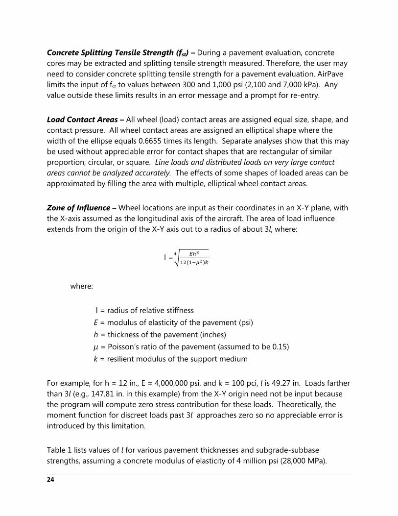
Concrete Splitting Tensile Strength (fst) – During a pavement evaluation, concrete cores may be extracted and splitting tensile strength measured. Therefore, the user may need to consider concrete splitting tensile strength for a pavement evaluation. AirPave limits the input of fst to values between 300 and 1,000 psi (2,100 and 7,000 kPa). Any value outside these limits results in an error message and a prompt for re-entry. Load Contact Areas – All wheel (load) contact areas are assigned equal size, shape, and contact pressure. All wheel contact areas are assigned an elliptical shape where the width of the ellipse equals 0.6655 times its length. Separate analyses show that this may be used without appreciable error for contact shapes that are rectangular of similar proportion, circular, or square. Line loads and distributed loads on very large contact areas cannot be analyzed accurately. The effects of some shapes of loaded areas can be approximated by filling the area with multiple, elliptical wheel contact areas. Zone of Influence – Wheel locations are input as their coordinates in an X-Y plane, with the X-axis assumed as the longitudinal axis of the aircraft. The area of load influence extends from the origin of the X-Y axis out to a radius of about 3l, where:
l =� 𝐸ℎ3
12(1−𝜇2)𝑘4
where:
l = radius of relative stiffness E = modulus of elasticity of the pavement (psi) h = thickness of the pavement (inches) µ = Poisson’s ratio of the pavement (assumed to be 0.15) k = resilient modulus of the support medium For example, for h = 12 in., E = 4,000,000 psi, and k = 100 pci, l is 49.27 in. Loads farther than 3l (e.g., 147.81 in. in this example) from the X-Y origin need not be input because the program will compute zero stress contribution for these loads. Theoretically, the moment function for discreet loads past 3l approaches zero so no appreciable error is introduced by this limitation. Table 1 lists values of l for various pavement thicknesses and subgrade-subbase strengths, assuming a concrete modulus of elasticity of 4 million psi (28,000 MPa).
25
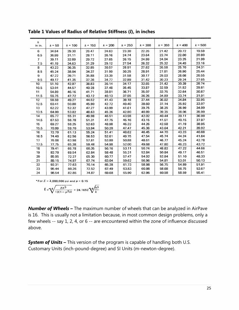
Table 1 Values of Radius of Relative Stiffness (l), in inches
Number of Wheels – The maximum number of wheels that can be analyzed in AirPave is 16. This is usually not a limitation because, in most common design problems, only a few wheels -- say 1, 2, 4, or 6 -- are encountered within the zone of influence discussed above. System of Units – This version of the program is capable of handling both U.S. Customary Units (inch-pound-degree) and SI Units (m-newton-degree).
26
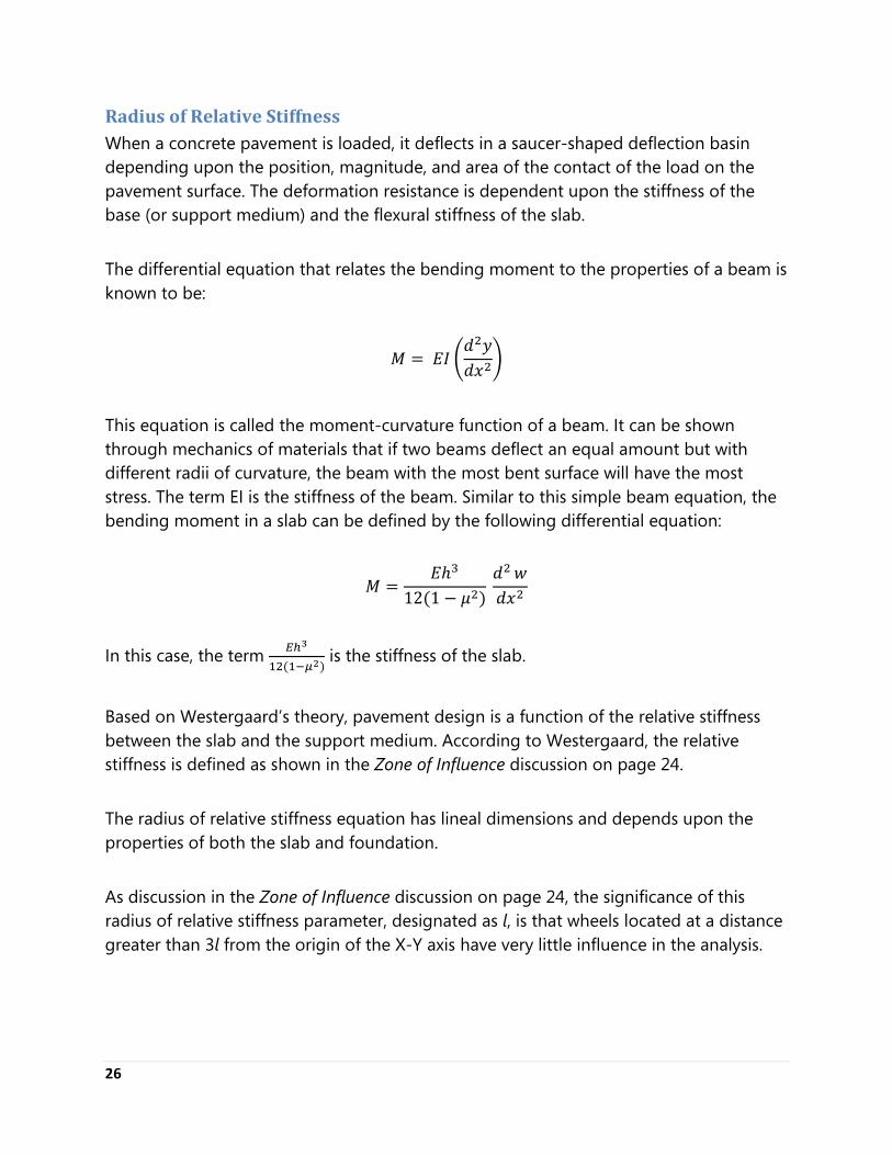
Radius of Relative Stiffness When a concrete pavement is loaded, it deflects in a saucer-shaped deflection basin depending upon the position, magnitude, and area of the contact of the load on the pavement surface. The deformation resistance is dependent upon the stiffness of the base (or support medium) and the flexural stiffness of the slab. The differential equation that relates the bending moment to the properties of a beam is known to be:
𝑀 = 𝐸𝐼 �𝑑2𝑦𝑑𝑥2
�
This equation is called the moment-curvature function of a beam. It can be shown through mechanics of materials that if two beams deflect an equal amount but with different radii of curvature, the beam with the most bent surface will have the most stress. The term EI is the stiffness of the beam. Similar to this simple beam equation, the bending moment in a slab can be defined by the following differential equation:
𝑀 =𝐸ℎ3
12(1 − 𝜇2) 𝑑2 𝑤𝑑𝑥2
In this case, the term 𝐸ℎ3
12(1−𝜇2) is the stiffness of the slab.
Based on Westergaard’s theory, pavement design is a function of the relative stiffness between the slab and the support medium. According to Westergaard, the relative stiffness is defined as shown in the Zone of Influence discussion on page 24. The radius of relative stiffness equation has lineal dimensions and depends upon the properties of both the slab and foundation. As discussion in the Zone of Influence discussion on page 24, the significance of this radius of relative stiffness parameter, designated as l, is that wheels located at a distance greater than 3l from the origin of the X-Y axis have very little influence in the analysis.

27
The physical definition of l is the distance from the load point (one load only) out to the point of contraflexure of the deflection basin. Bending moment along the X-axis is positive (tension at slab bottom) out to a distance of 1l, where it is zero; it then becomes negative, reaching a maximum negative value at 2l and approaches zero at 3l and beyond. Bending moment along the Y-axis is positive and decreases with distance. Based on the previous discussion, the user should recognize that, for an equal deflection, stiff support medium will result in higher stresses in concrete pavement than do those of lesser stiffness because of the differences in radius of curvature. Therefore, the user is cautioned against using a very stiff subbase, which will yield a smaller radius of relative stiffness, for design.
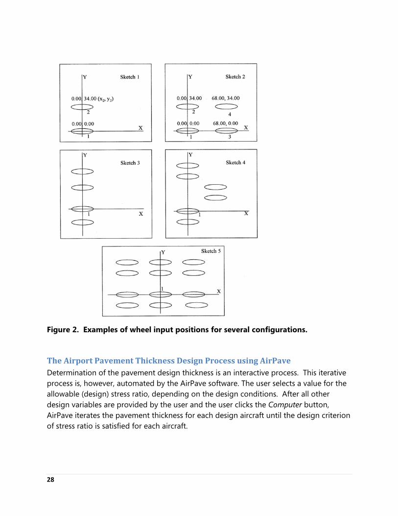
Coordinates of Wheels X-Y coordinates of wheel centers are used to specify wheel spacing, with the X-direction indicating the longitudinal axis of the aircraft. This means that spacing between dual wheels is specified as a Y-dimension and spacing between tandem sets is specified as an X-dimension. This convention must be followed because the computer program initially orients the major axis of each contact area ellipse in the X-direction. The following consideration is also important in specifying the wheel coordinates. The particular wheel in the gear that is judged closest to the location of maximum stress is designated as Wheel 1 and its coordinates are preset at X = 0.00, Y = 0.00. Of the two most closely spaced wheels in a complex configuration, the wheel closest to the gear center is usually selected as Wheel 1. The other wheels are numbered as desired and their X-Y coordinates are specified corresponding to their position relative to Wheel 1. Sketches 1 and 2 of Figure 2 illustrate the positions and wheel coordinates for dual wheel gear (FAA D) and for twin-tandem gear (FAA 2D). Sketches 3, 4, and 5 show the selection of Wheel 1 for more complex gear configurations. For multi-wheeled gears, the input should be such that the zone of influence will encompass as many wheels as possible.
28
Figure 2. Examples of wheel input positions for several configurations.
The Airport Pavement Thickness Design Process using AirPave Determination of the pavement design thickness is an interactive process. This iterative process is, however, automated by the AirPave software. The user selects a value for the allowable (design) stress ratio, depending on the design conditions. After all other design variables are provided by the user and the user clicks the Computer button, AirPave iterates the pavement thickness for each design aircraft until the design criterion of stress ratio is satisfied for each aircraft.
29
Selection of Allowable Pavement Stress
The allowable pavement stress represents a preselected maximum flexural stress caused by loads on wheels or other contact areas. This is termed "working stress," which is not to be confused with any other definition of the term. Two methods, described below, give guidance for the selection of the allowable stress. More details are given in References 1.
1. Safety Factor – A safety factor, as used in concrete pavement design, is the ratio of the concrete's flexural strength (i.e., modulus of rupture) to its allowable flexural stress (i.e., the working stress). The safety factor chosen for design depends on the expected frequency of loading of the heaviest aircraft and the degree of traffic channelization. The following safety factor ranges are suggested for design for vehicular traffic:
a. Channelized Traffic (wheel loads run in same path): 1.7 to 2.0 b. Distributed Traffic: 1.5 to 1.7
For pavement areas with only occasional operations of heavy aircraft, safety factors near the bottom of the ranges are appropriate. For areas with a few daily operations of heavy aircraft, use intermediate values. Values at the higher end of the ranges should be used if the frequency of heavy wheel load passes is great. A safety factor of 2.0 permits unlimited channelized load repetitions. Using a safety factor less than 2.0 may lead to a fatigue analysis being required, considering all aircraft and the number of operation of each. Such detailed fatigue analysis is outside of the scope of AirPave and would require additional considerations.
2. Stress Ratio – A more quantitative method for the user to determine the
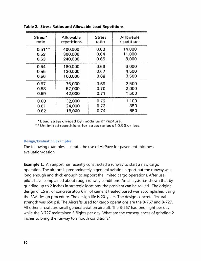
allowable stress is by the use of a stress ratio. The stress ratio is defined as the allowable stress divided by the modulus of rupture (or the inverse of the safety factor). Table 2 lists the allowable number of load repetitions vs. stress ratios. In using this method, the designer selects a design stress ratio. Assuming the user selects 0.50 (i.e., unlimited operations to the loading in question) as the design stress ratio, the designer would then select the aircraft expected to use the pavement, input the concrete material properties, run the program, and choose the design thickness for the aircraft that yields the thickest pavement. Selecting a stress ratio larger that 0.50 would require a fatigue analysis by computing the percentage of life used by each aircraft at the stress ratio.
30
Table 2. Stress Ratios and Allowable Load Repetitions
Design/Evaluation Examples
The following examples illustrate the use of AirPave for pavement thickness evaluation/design:
Example 1: An airport has recently constructed a runway to start a new cargo operation. The airport is predominately a general aviation airport but the runway was long enough and thick enough to support the limited cargo operations. After use, pilots have complained about rough runway conditions. An analysis has shown that by grinding up to 2 inches in strategic locations, the problem can be solved. The original design of 15 in. of concrete atop 6 in. of cement treated based was accomplished using the FAA design procedure. The design life is 20-years. The design concrete flexural strength was 650 psi. The Aircrafts used for cargo operations are the B-767 and B-727. All other aircraft are small general aviation aircraft. The B-767 had one flight per day while the B-727 maintained 3 flights per day. What are the consequences of grinding 2 inches to bring the runway to smooth conditions?
31
In-place conditions are:
· Fine grain soil: k = 100 pci · 6 in. of cement-tread subbase (CTB) · Acceptance testing shows the in-place concrete flexural strength to be between
700 and 877 psi
By inspection, the engineer determines that the airport only needs to examine the effects of the two cargo aircraft. In the AirPave program, the engineer enters the general project information and selects the interior loading condition because adequate load transfer is assumed. U.S. units will be used for this analysis. The analysis type will be pavement evaluation because the engineer is evaluating an in-place pavement. The pavement thickness is 15 in. but because the engineer wishes to analyze the effects of grinding 2 inches off the existing pavement he/she uses a thickness of 13 in. Next the engineer clicks on the Aircraft Loading button and selects the B-767 and B-727 aircraft from the AirPave aircraft library. (Note the heaviest versions of these two aircraft were chosen for this example (i.e., B-727-Adv. 200 and the B-767-200, Option 2)). The modulus of elasticity is assumed to be 4 million psi. The pavement design strength was 650 psi but acceptance testing during construction showed the in-place flexural concrete strength to be between 700-877 psi. The engineer can take advantage of the extra strength of the in-place concrete for this analysis, so the lowest in-place strength of 700 psi is chosen as the modulus of rupture. In lieu of rigorous testing of the in-place concrete, the engineer chooses to input the modulus of subgrade reaction based on the materials composition option in the program by selecting a fine grain soil with a 6 in. thick cement treated base, which yields a k-value of 490 pci. All the input fields are now populated and the engineer clicks the Compute button to run the evaluation.
Once the analysis is completed, the engineer views the AirPave-generated evaluation report. The following data is observed on the first page of the summary report:
Slab thickness: 13 in. (as input by the user)
32
Aircraft XMAX YMAX Maximum
Angle Maximum
Stress Stress Ratio
Allowable Total
Repetitions
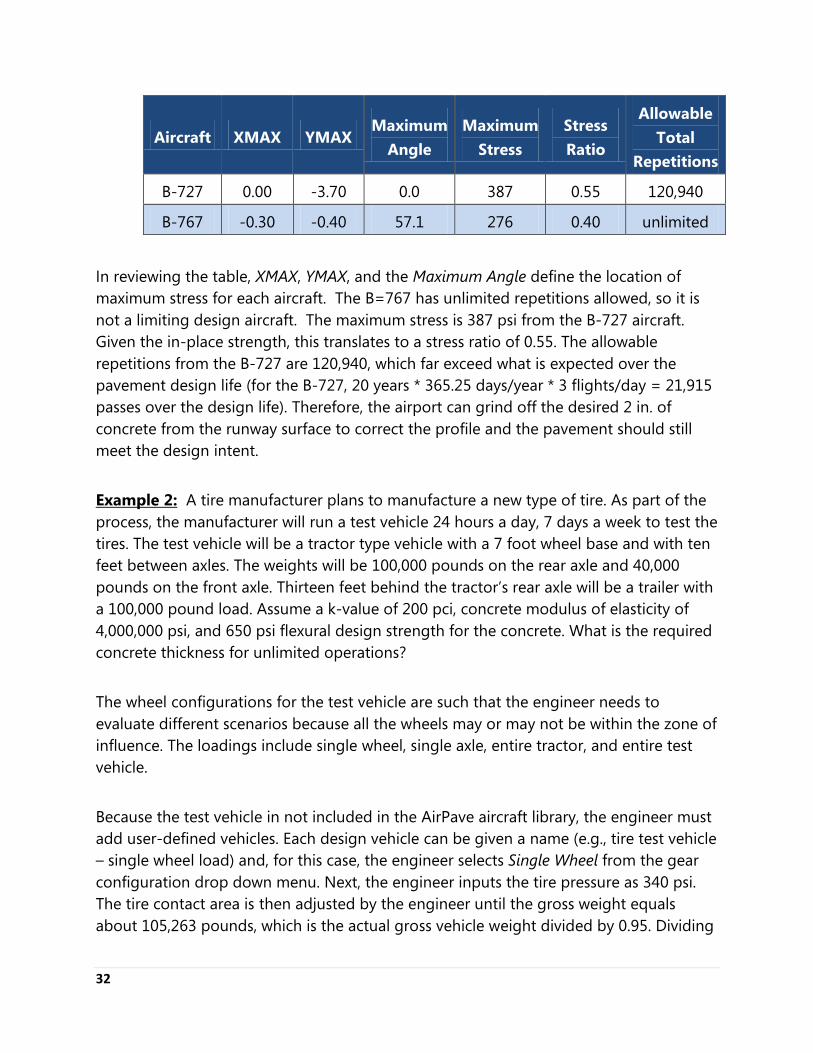
B-727 0.00 -3.70 0.0 387 0.55 120,940
B-767 -0.30 -0.40 57.1 276 0.40 unlimited
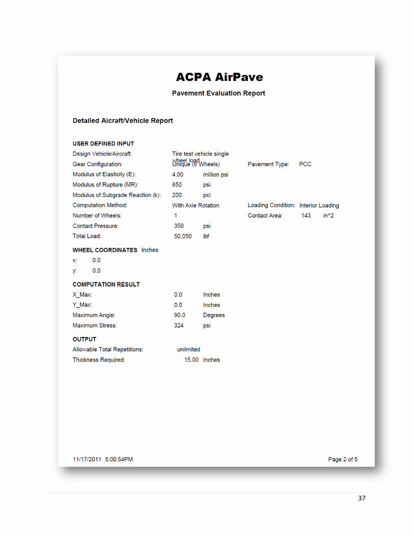
In reviewing the table, XMAX, YMAX, and the Maximum Angle define the location of maximum stress for each aircraft. The B=767 has unlimited repetitions allowed, so it is not a limiting design aircraft. The maximum stress is 387 psi from the B-727 aircraft. Given the in-place strength, this translates to a stress ratio of 0.55. The allowable repetitions from the B-727 are 120,940, which far exceed what is expected over the pavement design life (for the B-727, 20 years * 365.25 days/year * 3 flights/day = 21,915 passes over the design life). Therefore, the airport can grind off the desired 2 in. of concrete from the runway surface to correct the profile and the pavement should still meet the design intent. Example 2: A tire manufacturer plans to manufacture a new type of tire. As part of the process, the manufacturer will run a test vehicle 24 hours a day, 7 days a week to test the tires. The test vehicle will be a tractor type vehicle with a 7 foot wheel base and with ten feet between axles. The weights will be 100,000 pounds on the rear axle and 40,000 pounds on the front axle. Thirteen feet behind the tractor’s rear axle will be a trailer with a 100,000 pound load. Assume a k-value of 200 pci, concrete modulus of elasticity of 4,000,000 psi, and 650 psi flexural design strength for the concrete. What is the required concrete thickness for unlimited operations? The wheel configurations for the test vehicle are such that the engineer needs to evaluate different scenarios because all the wheels may or may not be within the zone of influence. The loadings include single wheel, single axle, entire tractor, and entire test vehicle. Because the test vehicle in not included in the AirPave aircraft library, the engineer must add user-defined vehicles. Each design vehicle can be given a name (e.g., tire test vehicle – single wheel load) and, for this case, the engineer selects Single Wheel from the gear configuration drop down menu. Next, the engineer inputs the tire pressure as 340 psi. The tire contact area is then adjusted by the engineer until the gross weight equals about 105,263 pounds, which is the actual gross vehicle weight divided by 0.95. Dividing
33
the gross weight by 0.95 is required because AirPave assume that 95 percent of the gross weight is carried by the all the main gear of the aircraft or vehicle – the aircraft nose gear is ignored because the assumption is that it carries only 5% of the load and is sufficiently far from the zone of influence. AirPave further assumes that ½ of the main gear weight is carried by one main gear, or in this case the single wheel with a 50,000 pound load. The contact area of 143 in.2 yields a gross weight of 105,368, which is close to what is required. The wheel coordinates for this case are (0, 0). To finish creating the model, the engineer updates the database to include this loading and clicks OK to return to the aircraft input window. The engineer starts the process over again and repeats until the remaining three loading conditions have been created. The input parameters to create the other loading conditions are as follows: Load Condition 2:
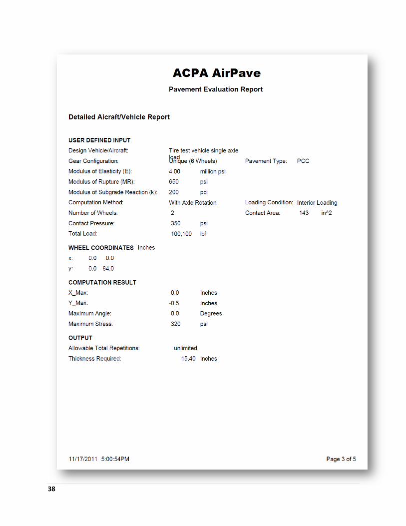
Wheel Coordinates: (0,0) and (0, 84) (84 inches is the spacing on the axle) Name: Tire test vehicle – single axle Gear Configuration: unique – 2 wheels (from the drop down menu) Tire Pressure: 340 psi Contact Area: 143 Gross Weight: 210,737 Note: the gross weight in this case is twice the 100,000 pounds plus an additional 5% to account for the AirPave assumptions (i.e., ½ of 95% of the gross weight carried by one main gear). These input parameters yield a slightly higher weight in the analysis, which is conservative.
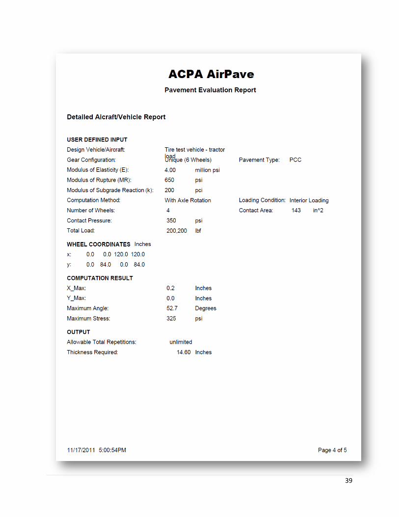
Load Condition 3: Wheel Coordinates: (0,0); (0,84); (120, 0) and (120, 84)
(120 inches is the spacing between the axles on the tractor) Name: Tire test vehicle – tractor load Gear Configuration: unique – 4 wheels (from the drop down menu) Tire Pressure: 340 psi Contact Area: 143
34
Gross Weight: 421,474 Note: the gross weight for this case is 4 times the 100,000 pound axle load plus an additional 5%. Also note that AirPave cannot account for a variable weight between wheels so we will conservatively assume the front axle also carries a 100,000 pound load. This is considered a valid approach to the problem and should not have profound effects on the analysis because the second axle is near or after the inflection point of the zone of influence.
Load Condition 4: Wheel Coordinates: (0,0); (0,84); (120, 0); (120, 84); (-156.0) and (-156, 84)
(120 inches is the spacing between the axles on the tractor) (156 inches is the distance from the tractor to the trailer)
Name: Entire test vehicle Gear Configuration: unique – 6 wheels (from the drop down menu) Tire Pressure: 340 psi Contact Area: 143 Gross Weight: 632,212 Note: the gross weight for this case is 6 times the 100,000 pound axle load plus an additional 5%. Refer to the previous model for discussion about the reduce weight of the front tractor axle.
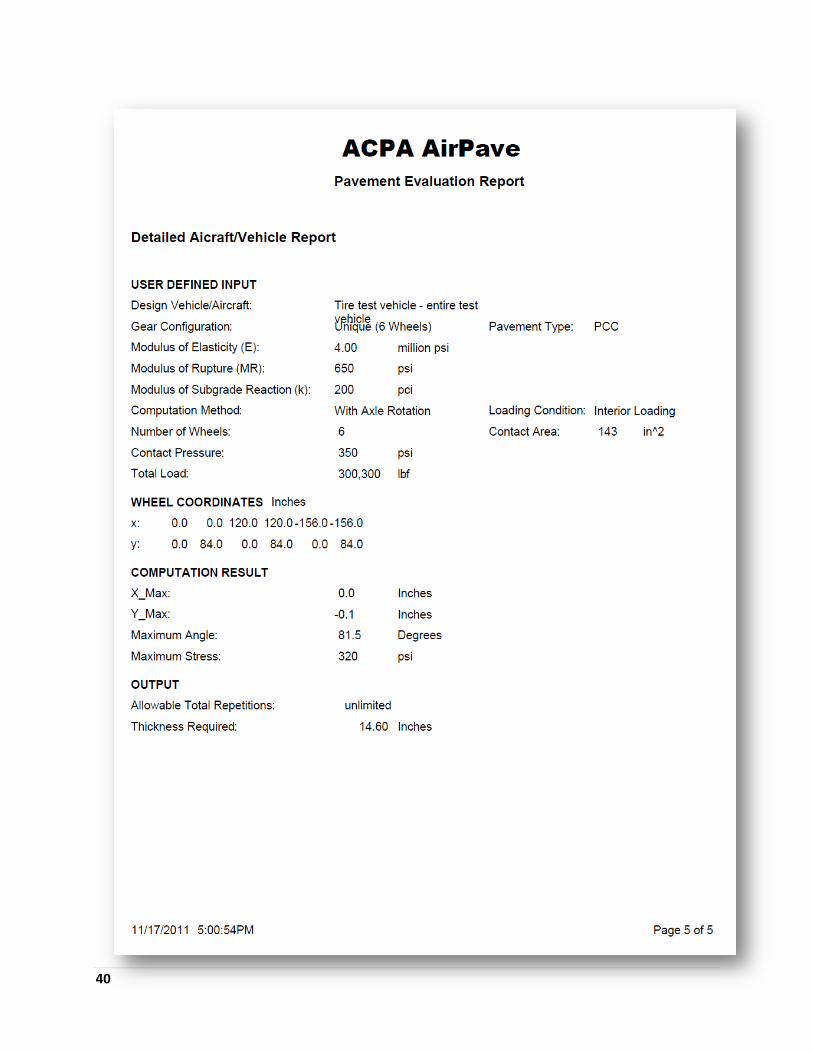
All four models should now be included in the AirPave aircraft/vehicle database. The engineer then ensures that all four vehicles have been checked and no other aircraft are checked. All four vehicles then appear in the Aircraft/Vehicles Selected area in the main AirPave window. The engineer would check that the Interior Loading condition button is checked and that the appropriate Units are checked as required. For this example, we will use U.S. units. Because this a design problem, the engineer selects the Pavement Design analysis type option. To allow for the minimum thickness for unlimited operations, the engineer uses a design stress ratio of 0.50.
35
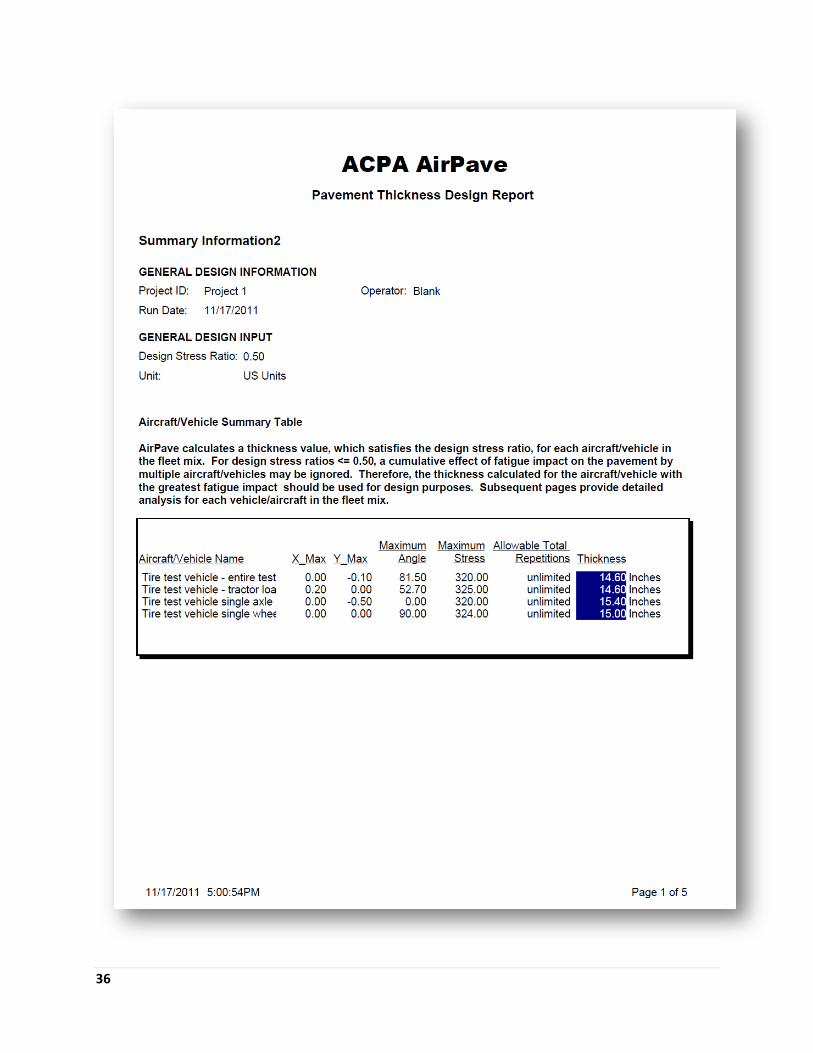
The engineer then enters the design modulus of elasticity and 4.0 million psi, the modulus of rupture as 650 psi, and the modulus of subgrade reaction as 200 pci. The engineer has now populated all required design parameters. Once the engineer verifies that all input parameter are as desired, the design is computed and the reports reviewed. The report (see the next 5 pages) summarizes the design on its first page by providing the maximum stress and required thickness for each load case to provide unlimited operations. For this example, the engineer would select the worst case loading, which is the single axle load requiring 15. 4 inches of concrete, as the design load. The concrete thickness is then rounded up to 15 ½ - 16 inches or down to 15 inches, using engineering judgment. The engineer could use subsequent AirPave analyses to evaluate the effects of rounding up to 16 inches or down to 15 inches to aid in making a decision on what thickness should be used. In summary, this example shows how to use AirPave to analyze and design a concrete pavement for an unusual application. The user is cautioned to make sure that the AirPave assumptions are accounted for during unique design or evaluation cases such as this.
36
37
38
39
40
41
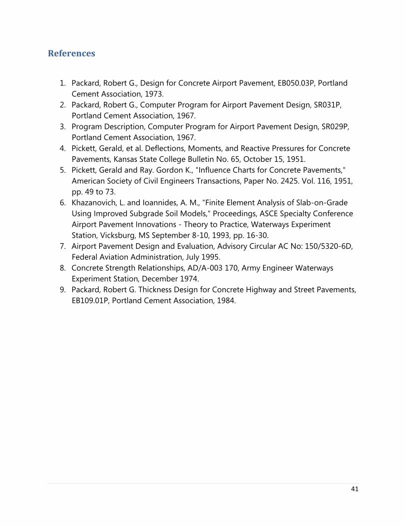
References
1. Packard, Robert G., Design for Concrete Airport Pavement, EB050.03P, Portland Cement Association, 1973.
2. Packard, Robert G., Computer Program for Airport Pavement Design, SR031P, Portland Cement Association, 1967.
3. Program Description, Computer Program for Airport Pavement Design, SR029P, Portland Cement Association, 1967.
4. Pickett, Gerald, et al. Deflections, Moments, and Reactive Pressures for Concrete Pavements, Kansas State College Bulletin No. 65, October 15, 1951.
5. Pickett, Gerald and Ray. Gordon K., "Influence Charts for Concrete Pavements," American Society of Civil Engineers Transactions, Paper No. 2425. Vol. 116, 1951, pp. 49 to 73.
6. Khazanovich, L. and Ioannides, A. M., "Finite Element Analysis of Slab-on-Grade Using Improved Subgrade Soil Models," Proceedings, ASCE Specialty Conference Airport Pavement Innovations - Theory to Practice, Waterways Experiment Station, Vicksburg, MS September 8-10, 1993, pp. 16-30.
7. Airport Pavement Design and Evaluation, Advisory Circular AC No: 150/5320-6D, Federal Aviation Administration, July 1995.
8. Concrete Strength Relationships, AD/A-003 170, Army Engineer Waterways Experiment Station, December 1974.
9. Packard, Robert G. Thickness Design for Concrete Highway and Street Pavements, EB109.01P, Portland Cement Association, 1984.

42
This Page Left Intentionally Blank

This Page Left Intentionally Blank
AirPave Guide
This publication is intended SOLELY for use by PROFESSIONAL PERSONNEL who are competent to evaluate the significance and limitations of the information provided herein, and who will accept total responsibility for the application of this information. The American Concrete Pavement Association DISCLAIMS any and all RESPONSIBILITY and LIABILITY for the accuracy of and the application of the information contained in this publication to the full extent permitted by law.
American Concrete Pavement Association 9450 Bryn Mawr, Suite 150 Rosemont, IL 60018 www.acpa.org
AirPave11 (SW01)