AirLINE Type 8652 - flutech.co.th
12
Additional Instructions Zusatzanleitung Instruction supplémentaire BVS 20 ATEX E 031 U / IECEx BVS 20.0024 U AirLINE Type 8652 Modular valve island for pneumatics Modulare Ventilinsel für Pneumatik L’îlot de vannes modulaire pour système pneumatique
Transcript of AirLINE Type 8652 - flutech.co.th

Additional InstructionsZusatzanleitungInstruction supplémentaire
BVS 20 ATEX E 031 U / IECEx BVS 20.0024 UAirLINE Type 8652
Modular valve island for pneumaticsModulare Ventilinsel für PneumatikL’îlot de vannes modulaire pour système pneumatique

We reserve the right to make technical changes without notice.Technische Änderungen vorbehalten.Sous réserve de modifications techniques.
© Bürkert Werke GmbH & Co. KG, 2020
Operating Instructions 2011/01_EU-ML_00815347 / Original DE

3
BVS 20 ATEX E 031 UIECEx BVS 20.0024 U
1 AddITIonAl InSTrUCTIonS for USE In ThE poTEnTIAlly EXploSIVE ATmoSphErE
(ATEX Directive 2014/34/EU)If Bürkert devices with the code PX68 are used in the potentially explosive atmosphere, follow not only the respective operating instructions, but also the information in these additional instructions.Keep these instructions in a location which is easily accessible to every user and make them available to every new owner of the device.
Important safety information!
Carefully read through these additional instructions. Note in particular the chapters “Intended use” and “Special safety instructions”.
▶ These additional instructions must be read, understood and followed.
▶ The operating instructions for the valve island AirLINE Type 8652 must be read, understood and followed.
The operating instructions for the valve island AirLINE Type 8652 can be found on the Internet at: www.burkert.com
1 AddItIonAl InstructIons for use In the potentIAlly explosIve Atmosphere ......................... 3
1.1 Definition of terms ....................................................... 41.2 Symbols ....................................................................... 4
2 Intended use .................................................................... 5
3 sAfety InstructIons In the potentIAlly explosIve Atmosphere .................................................. 6
4 specIAl condItIons for generAl use ...................... 74.1 Special conditions for using the hot swap function .... 7
5 explosIon protectIon ApprovAl ............................... 8
6 technIcAl dAtA ................................................................ 86.1 Adhesive labels for the potentially explosive atmosphere ................................................................. 86.2 Operating conditions ................................................. 106.3 Service temperature .................................................. 106.4 Permitted device variants .......................................... 106.5 Conformity ................................................................. 106.6 Standards .................................................................. 10
Additional instructions for use in the potentially explosive atmosphere
English

4
BVS 20 ATEX E 031 UIECEx BVS 20.0024 U
1.1 Definition of terms
Term In these instructions stands for
Actuator, process valve
Pneumatic consumer controlled by the valve island
büS Bürkert system bus; a communication bus developed by Bürkert, based on the CANopen protocol
EVS External valve voltage shutdownValves can be de-energised irrespective of the control signals from the bus master. This safety shutdown can be applied to individual valves, valve units or the entire valve block.
Ex area Potentially explosive atmosphere
Device, valve island
Valve island AirLINE Type 8652
SIA variant Variant for safety-related shutdown (see “EVS”)
Pneumatic valve, pilot valve
Pneumatic slide valve that can be integrated into the valve block
1.2 Symbols
Danger
Warns of an immediate danger. ▶ Failure to observe will result in death or serious injuries.
WarnIng
Warns of a potentially hazardous situation. ▶ Failure to observe these instructions may result in serious injuries or death.
CauTIon
Warns of a potential danger. ▶ Failure to observe may result in moderate or minor injuries.
noTe
Warns of damage.
Important tips and recommendations.
Refers to information in these operating instructions or in other documentation.
▶ Designates instructions to avoid danger. → Designates a procedure which you must carry out.
Additional instructions for use in the potentially explosive atmosphere
English
5
Intended use
BVS 20 ATEX E 031 UIECEx BVS 20.0024 U
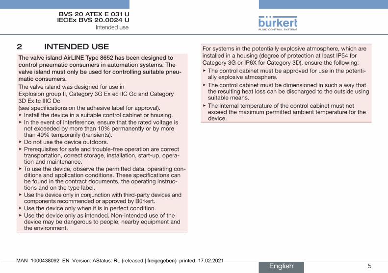
2 InTEndEd USEthe valve island AirlIne type 8652 has been designed to control pneumatic consumers in automation systems. the valve island must only be used for controlling suitable pneu-matic consumers.The valve island was designed for use in Explosion group II, Category 3G Ex ec IIC Gc and Category 3D Ex tc IIIC Dc (see specifications on the adhesive label for approval).
▶ Install the device in a suitable control cabinet or housing. ▶ In the event of interference, ensure that the rated voltage is not exceeded by more than 10% permanently or by more than 40% temporarily (transients).
▶ Do not use the device outdoors. ▶ Prerequisites for safe and trouble-free operation are correct transportation, correct storage, installation, start-up, opera-tion and maintenance.
▶ To use the device, observe the permitted data, operating con-ditions and application conditions. These specifications can be found in the contract documents, the operating instruc-tions and on the type label.
▶ Use the device only in conjunction with third-party devices and components recommended or approved by Bürkert.
▶ Use the device only when it is in perfect condition. ▶ Use the device only as intended. Non-intended use of the device may be dangerous to people, nearby equipment and the environment.
For systems in the potentially explosive atmosphere, which are installed in a housing (degree of protection at least IP54 for Category 3G or IP6X for Category 3D), ensure the following:
▶ The control cabinet must be approved for use in the potenti-ally explosive atmosphere.
▶ The control cabinet must be dimensioned in such a way that the resulting heat loss can be discharged to the outside using suitable means.
▶ The internal temperature of the control cabinet must not exceed the maximum permitted ambient temperature for the device.
English

6
BVS 20 ATEX E 031 UIECEx BVS 20.0024 U
3 SAfETy InSTrUCTIonS In ThE poTEnTIAlly EXploSIVE ATmoSphErE
To prevent a risk of explosion, follow not only the safety instruc-tions in the operating instructions, but also the safety instructions in these additional instructions.
danger due to electric voltage. ▶ Before working on the device or system, switch off the power supply. Secure against reactivation.
▶ In the potentially explosive atmosphere, only plug or unplug the connection terminals in a de-energised state for the functions – 24 V power supply – SIA – EVS – Digital inputs (for exception see chapter “4”).
▶ In the potentially explosive atmosphere, only plug or unplug fixed cable connections that can be inserted into the connec-tion terminals in a de-energised state. De-energise all circuits connected to the connection terminals.
▶ Usage of the hot swap function is prohibited in the potentially explosive atmosphere (for exception see chapter “4.1”).
▶ Observe the applicable accident prevention and safety regu-lations for electrical devices.
risk of explosion due to electrostatic charge.If there is a sudden discharge of electrostatically charged devices or persons, there is a risk of explosion in the potentially explosive atmosphere.
▶ Use suitable measures to ensure that electrostatic charges cannot occur in the potentially explosive atmosphere.
▶ Clean the device surface by gently wiping it with a damp or anti-static cloth only.
risk of injury due to improper installation, operation or maintenance.
▶ Only qualified technicians may perform installation work, operating procedures or maintenance work.
▶ Perform installation work and maintenance work using suit-able tools only.
general hazardous situations.To prevent injuries, observe the following:
▶ Operate the device only when it is in perfect condition and in accordance with the operating instructions.
▶ Observe applicable safety regulations (also national safety regulations) as well as the general rules of technology during setup and operation.
▶ Do not repair the device, but replace it with an equivalent device. Repairs may be carried out by the manufacturer only.
▶ Do not place the device under mechanical stress (e.g. by placing objects on it or standing on it).
▶ Do not subject the device to mechanical and/or thermal stresses/influences which exceed the limits described in the operating instructions.
Safety instructions in the potentially explosive atmosphere
English

7
BVS 20 ATEX E 031 UIECEx BVS 20.0024 U
4 SpECIAl CondITIonS for gEnErAl USE
▶ For type of protection “ec”: Install the device in a housing which meets the applicable requirements of the type of protection “ec” according to EN/IEC 60079-0 and EN/IEC 60079-7 and has a degree of pro-tection of at least IP54.
▶ For type of protection “tc”: Install the device in a housing which meets the applicable requirements of the type of protection “tc” according to EN/IEC 60079-0 and EN/IEC 60079-31 and has a degree of pro-tection of at least IP6X.
▶ Use the device only in an area which has minimum pollution degree 2, as defined in IEC 60991-1.
▶ Ensure that the transient protection has been set to a value which does not exceed 140% of the rated peak voltage value on the supply connections of the device.
▶ In the potentially explosive atmosphere, only plug or unplug the connection terminals in a de-energised state for the functions – 24 V power supply – SIA – EVS – Digital inputsIf it can be verified and ensured with suitable testing materials that there will not be a potentially explosive atmosphere over a certain period of time, the plugging/unplugging of con-nection terminals is always functionally possible during this time.
▶ In the potentially explosive atmosphere, only plug or unplug fixed cable connections that can be inserted into the connec-tion terminals in a de-energised state. De-energise all circuits connected to the connection terminals.
4.1 Special conditions for using the hot swap function
Usage of the hot swap function is prohibited in the potentially explosive atmosphere.If it can be verified and ensured with suitable testing materials that there will not be a potentially explosive atmosphere over a certain period of time, the removal or addition of a valve is per-mitted during this time.Only specially trained personnel may perform the hot swap function.
Special conditions for general use
English

8
Explosion protection approval
BVS 20 ATEX E 031 UIECEx BVS 20.0024 U
5 EXploSIon proTECTIon ApproVAl
The explosion protection approval is only valid if you use the modules and components approved by Bürkert as described in these operating instructions.The devices may be used only in combination with the valve types approved by Bürkert, otherwise the explosion protection approval will expire.In the event of unauthorised changes to the system, modules or components, the explosion protection approval will also expire.The type examination certificates BVS 20 ATEX E 031 U IECEx BVS 20.0024 U were issued by DEKRA Testing and Certification GmbH Fachstelle für Sicherheit elektrischer Betriebsmittel – BVS 44809 Bochum, Germany Production is audited by the PTB (CE0102).
6 TEChnICAl dATA To prevent a risk of explosion, observe not only the technical data in the operating instructions, but also the technical data in these additional instructions.
6.1 Adhesive labels for the potentially explosive atmosphere
Valve islands for the potentially explosive atmosphere always have 2 adhesive labels:
Line:1234
567
Fig. 1: Adhesive label for the potentially explosive atmosphere (example)
Type 8652 AirLINE3-10 bar-10...+55°C24V 3AS/N 0W14AL12345678
Mad
e in
Ger
man
yD
-746
53 In
gelfi
ngen
Proc. Cont. EqE238179
Line:89
1011121314
Fig. 2: General adhesive label (example)
English

9
Technical data
BVS 20 ATEX E 031 UIECEx BVS 20.0024 U
line description Specification
1 ATEX approval number BVS 20 ATEX E 031 U
2 Identification of the Ex protection ATEX gas/dust
II 3G Ex ec IIC Gc/ II 3D Ex tc IIIC Dc
3 Certificate number IECEx IECEx BVS 20.0024 U
4 Identification of the Ex protection IECEx gas/dust
Ex ec IIC Gc/ Ex tc IIIC Dc
5 Safety note Electrical connection
6 Ex logo
7 Safety note Hot swap
8 Device type AirLINE Type 8652
9 Pressure range 3–10 bar
10 Ambient temperature range –10 to+55 °C
11 Rated voltage 24 V
Current consumption 3 A
12 Serial no. S/N 0 (example)
13 Manufacture code, coded W14AL (example)
14 Device order number 12345678 (example)
Tab. 1: Description of the specifications on both adhesive labels
6.1.1 Additional adhesive label
An additional adhesive label (in multiple copies) is included in the scope of delivery for the device:
Fig. 3: Additional adhesive label
If the existing safety information on the adhesive label for the potentially explosive atmosphere (“Fig. 1”) is not visible or only partially visible due to the installation position of the valve island in the control cabinet:
→ Attach an additional adhesive label to the valve island so that it is clearly visible.
English

10
Technical data
BVS 20 ATEX E 031 UIECEx BVS 20.0024 U
6.2 Operating conditions
Rated voltage 24 V Nominal power Depending on the structure Ambient temperature range
–10 to +55 °C
Solenoid valve types used
Type 6164 (pilot control of the pneumatic valves Type 6534)
Maximum number of valve functions
48
If device structures have fewer than 48 valve functions, less power is converted, so that the considered and measured maximum temperatures are the same or lower.
6.3 Service temperatureAt a maximum ambient temperature of +55 °C inside the control cabinet, the limits of temperature class T4 are not exceeded.If variant AirLine Quick is used in a control cabinet (refer to oper-ating instructions Type 8652), the maximum service temperature on the outside does not exceed +80 °C at any point.
6.4 Permitted device variantsDevice variants with the following properties are permitted in the potentially explosive atmosphere:• Maximum 48 valve functions• Combination of pneumatic valve functions
Type 6534 Type 6534, SIA variant
The maximum number of 48 valve functions must not be exceeded.
• EVS (external valve voltage shut-off)• Electronic module with digital inputs• Connection module with pressure sensor
6.5 ConformityThe device conforms to the EU directives as per the EU Declaration of Conformity.
6.6 StandardsThe applied standards, which are used to verify compliance with the directives, can be found in the type examination certificate and/or the EU Declaration of Conformity.
English

www.burkert.com