AirGate-Modbus - Data Loggers and Data Acquisition Systems for
13
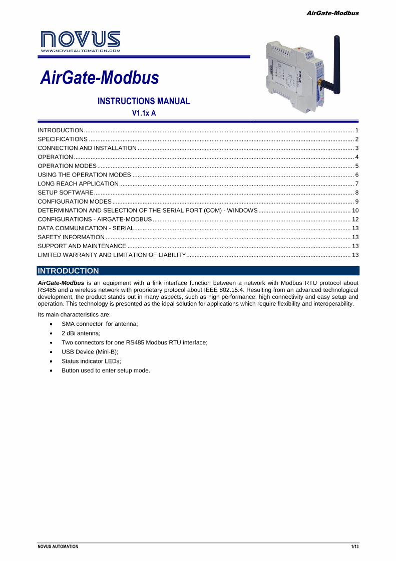
AirGate-Modbus NOVUS AUTOMATION 1/13 AirGate-Modbus INSTRUCTIONS MANUAL V1.1x A INTRODUCTION ................................................................................................................................................................. 1 SPECIFICATIONS .............................................................................................................................................................. 2 CONNECTION AND INSTALLATION ................................................................................................................................. 3 OPERATION ....................................................................................................................................................................... 4 OPERATION MODES ......................................................................................................................................................... 5 USING THE OPERATION MODES .................................................................................................................................... 6 LONG REACH APPLICATION ............................................................................................................................................ 7 SETUP SOFTWARE ........................................................................................................................................................... 8 CONFIGURATION MODES ................................................................................................................................................ 9 DETERMINATION AND SELECTION OF THE SERIAL PORT (COM) - WINDOWS ....................................................... 10 CONFIGURATIONS - AIRGATE-MODBUS ...................................................................................................................... 12 DATA COMMUNICATION - SERIAL ................................................................................................................................. 13 SAFETY INFORMATION .................................................................................................................................................. 13 SUPPORT AND MAINTENANCE ..................................................................................................................................... 13 LIMITED WARRANTY AND LIMITATION OF LIABILITY .................................................................................................. 13 INTRODUCTION AirGate-Modbus is an equipment with a link interface function between a network with Modbus RTU protocol about RS485 and a wireless network with proprietary protocol about IEEE 802.15.4. Resulting from an advanced technological development, the product stands out in many aspects, such as high performance, high connectivity and easy setup and operation. This technology is presented as the ideal solution for applications which require flexibility and interoperability. Its main characteristics are: SMA connector for antenna; 2 dBi antenna; Two connectors for one RS485 Modbus RTU interface; USB Device (Mini-B); Status indicator LEDs; Button used to enter setup mode.
Transcript of AirGate-Modbus - Data Loggers and Data Acquisition Systems for
AirGate-Modbus
NOVUS AUTOMATION 1/13
AirGate-Modbus INSTRUCTIONS MANUAL
V1.1x A
INTRODUCTION ................................................................................................................................................................. 1 SPECIFICATIONS .............................................................................................................................................................. 2 CONNECTION AND INSTALLATION ................................................................................................................................. 3 OPERATION ....................................................................................................................................................................... 4 OPERATION MODES ......................................................................................................................................................... 5 USING THE OPERATION MODES .................................................................................................................................... 6 LONG REACH APPLICATION ............................................................................................................................................ 7 SETUP SOFTWARE ........................................................................................................................................................... 8 CONFIGURATION MODES ................................................................................................................................................ 9 DETERMINATION AND SELECTION OF THE SERIAL PORT (COM) - WINDOWS ....................................................... 10 CONFIGURATIONS - AIRGATE-MODBUS ...................................................................................................................... 12 DATA COMMUNICATION - SERIAL ................................................................................................................................. 13 SAFETY INFORMATION .................................................................................................................................................. 13 SUPPORT AND MAINTENANCE ..................................................................................................................................... 13 LIMITED WARRANTY AND LIMITATION OF LIABILITY .................................................................................................. 13
INTRODUCTION
AirGate-Modbus is an equipment with a link interface function between a network with Modbus RTU protocol about RS485 and a wireless network with proprietary protocol about IEEE 802.15.4. Resulting from an advanced technological development, the product stands out in many aspects, such as high performance, high connectivity and easy setup and operation. This technology is presented as the ideal solution for applications which require flexibility and interoperability.
Its main characteristics are:
SMA connector for antenna;
2 dBi antenna;
Two connectors for one RS485 Modbus RTU interface;
USB Device (Mini-B);
Status indicator LEDs;
Button used to enter setup mode.
AirGate-Modbus
NOVUS AUTOMATION 2/13
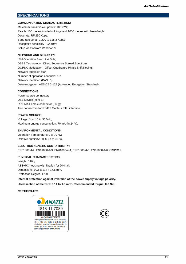
SPECIFICATIONS
COMMUNICATION CHARACTERISTICS:
Maximum transmission power: 100 mW;
Reach: 100 meters inside buildings and 1000 meters with line-of-sight;
Data rate: RF 250 Kbps;
Baud rate serial: 1.200 to 115.2 Kbps;
Receptor's sensibility - 92 dBm;
Setup via Software Windows®.
NETWORK AND SECURITY:
ISM Operation Band: 2.4 GHz;
DSSS Technology - Direct Sequence Spread Spectrum;
OQPSK Modulation - Offset Quadrature Phase Shift Keying;
Network topology: star;
Number of operation channels: 16;
Network Identifier: (PAN ID);
Data encryption: AES-CBC-128 (Advanced Encryption Standard).
CONNECTIONS:
Power source connector;
USB Device (Mini-B);
RP SMA Female connector (Plug);
Two connectors for RS485 Modbus RTU interface.
POWER SOURCE:
Voltage: from 10 to 35 Vdc;
Maximum energy consumption: 70 mA (in 24 V).
ENVIRONMENTAL CONDITIONS:
Operation Temperature: 0 to 70 °C;
Relative humidity: 80 % up to 30 ºC.
ELECTROMAGNETIC COMPATIBILITY:
EN61000-4-2, EN61000-4-3, EN61000-4-4, EN61000-4-5, EN61000-4-6, CISPR11.
PHYSICAL CHARACTERISTICS:
Weight: 110 g.
ABS+PC housing with fixation for DIN rail;
Dimensions: 99.5 x 114 x 17.5 mm.
Protection Degree: IP20
Internal protection against inversion of the power supply voltage polarity.
Used section of the wire: 0.14 to 1.5 mm². Recommended torque: 0.8 Nm.
CERTIFICATES:
AirGate-Modbus
NOVUS AUTOMATION 3/13
CONNECTION AND INSTALLATION
MECHANICAL INSTALLATION
AirGate-Modbus has its own enclosure, to be installed in a 35 mm trail.
For the installation in the trail, the metallic hook in the base must be located and pressed against the trail.
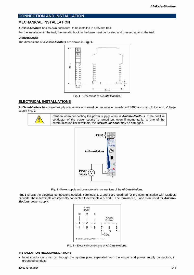
DIMENSIONS:
The dimensions of AirGate-Modbus are shown in Fig. 1.
Fig. 1 - Dimensions of AirGate-Modbus.
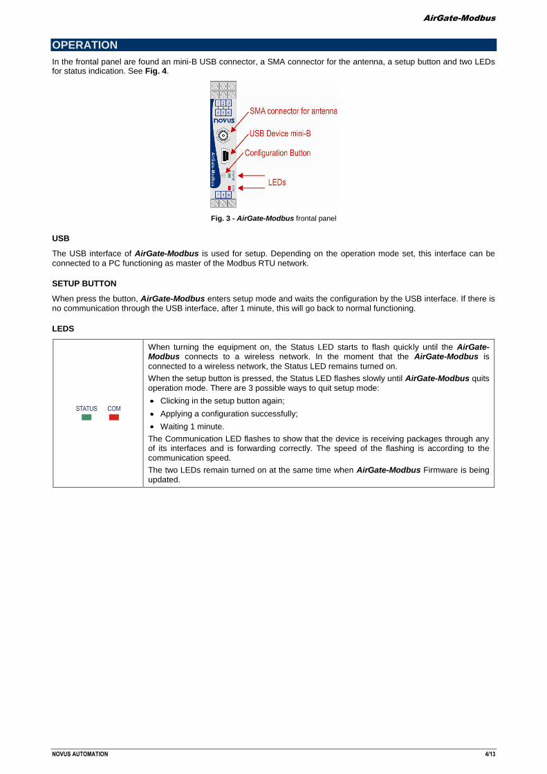
ELECTRICAL INSTALLATIONS
AirGate-Modbus has power supply connectors and serial communication interface RS485 according to Legend: Voltage supply Fig. 2.
Caution when connecting the power supply wires in AirGate-Modbus. If the positive conductor of the power source is turned on, even if momentarily, to one of the communication link terminals, the AirGate-Modbus may be damaged.
Fig. 2 - Power supply and communication connections of the AirGate-Modbus.
Fig. 3 shows the electrical connections needed. Terminals 1, 2 and 3 are destined for the communication with Modbus network. These terminals are internally connected to terminals 4, 5 and 6. The terminals 7, 8 and 9 are used for AirGate-Modbus power supply.
Fig. 2 – Electrical connections of AirGate-Modbus.
INSTALLATION RECOMMENDATIONS
Input conductors must go through the system plant separated from the output and power supply conductors, in grounded conduits.
AirGate-Modbus
NOVUS AUTOMATION 4/13
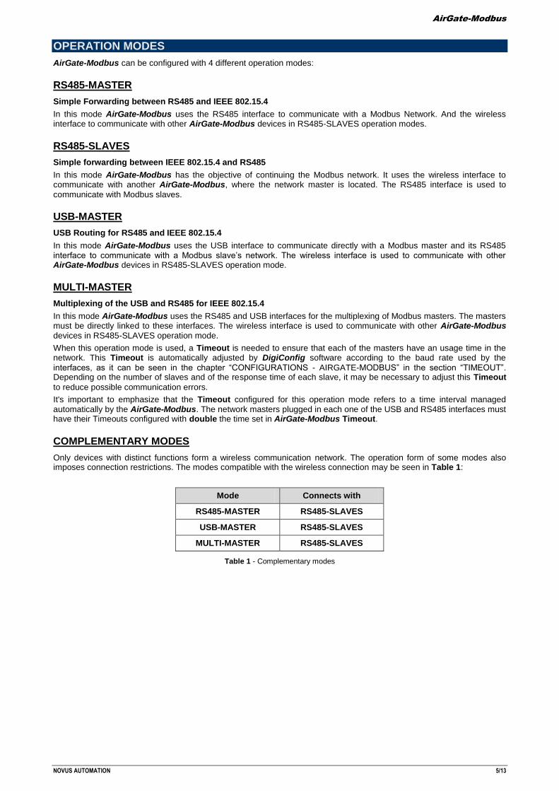
OPERATION
In the frontal panel are found an mini-B USB connector, a SMA connector for the antenna, a setup button and two LEDs for status indication. See Fig. 4.
Fig. 3 - AirGate-Modbus frontal panel
USB
The USB interface of AirGate-Modbus is used for setup. Depending on the operation mode set, this interface can be
connected to a PC functioning as master of the Modbus RTU network.
SETUP BUTTON
When press the button, AirGate-Modbus enters setup mode and waits the configuration by the USB interface. If there is no communication through the USB interface, after 1 minute, this will go back to normal functioning.
LEDS
When turning the equipment on, the Status LED starts to flash quickly until the AirGate-Modbus connects to a wireless network. In the moment that the AirGate-Modbus is
connected to a wireless network, the Status LED remains turned on.
When the setup button is pressed, the Status LED flashes slowly until AirGate-Modbus quits operation mode. There are 3 possible ways to quit setup mode:
Clicking in the setup button again;
Applying a configuration successfully;
Waiting 1 minute.
The Communication LED flashes to show that the device is receiving packages through any of its interfaces and is forwarding correctly. The speed of the flashing is according to the communication speed.
The two LEDs remain turned on at the same time when AirGate-Modbus Firmware is being updated.
AirGate-Modbus
NOVUS AUTOMATION 5/13
OPERATION MODES
AirGate-Modbus can be configured with 4 different operation modes:
RS485-MASTER
Simple Forwarding between RS485 and IEEE 802.15.4
In this mode AirGate-Modbus uses the RS485 interface to communicate with a Modbus Network. And the wireless interface to communicate with other AirGate-Modbus devices in RS485-SLAVES operation modes.
RS485-SLAVES
Simple forwarding between IEEE 802.15.4 and RS485
In this mode AirGate-Modbus has the objective of continuing the Modbus network. It uses the wireless interface to communicate with another AirGate-Modbus, where the network master is located. The RS485 interface is used to
communicate with Modbus slaves.
USB-MASTER
USB Routing for RS485 and IEEE 802.15.4
In this mode AirGate-Modbus uses the USB interface to communicate directly with a Modbus master and its RS485 interface to communicate with a Modbus slave’s network. The wireless interface is used to communicate with other AirGate-Modbus devices in RS485-SLAVES operation mode.
MULTI-MASTER
Multiplexing of the USB and RS485 for IEEE 802.15.4
In this mode AirGate-Modbus uses the RS485 and USB interfaces for the multiplexing of Modbus masters. The masters must be directly linked to these interfaces. The wireless interface is used to communicate with other AirGate-Modbus devices in RS485-SLAVES operation mode.
When this operation mode is used, a Timeout is needed to ensure that each of the masters have an usage time in the network. This Timeout is automatically adjusted by DigiConfig software according to the baud rate used by the
interfaces, as it can be seen in the chapter “CONFIGURATIONS - AIRGATE-MODBUS” in the section “TIMEOUT”. Depending on the number of slaves and of the response time of each slave, it may be necessary to adjust this Timeout
to reduce possible communication errors.
It's important to emphasize that the Timeout configured for this operation mode refers to a time interval managed automatically by the AirGate-Modbus. The network masters plugged in each one of the USB and RS485 interfaces must have their Timeouts configured with double the time set in AirGate-Modbus Timeout.
COMPLEMENTARY MODES
Only devices with distinct functions form a wireless communication network. The operation form of some modes also imposes connection restrictions. The modes compatible with the wireless connection may be seen in Table 1:
Mode Connects with
RS485-MASTER RS485-SLAVES
USB-MASTER RS485-SLAVES
MULTI-MASTER RS485-SLAVES
Table 1 - Complementary modes
AirGate-Modbus
NOVUS AUTOMATION 6/13
USING THE OPERATION MODES
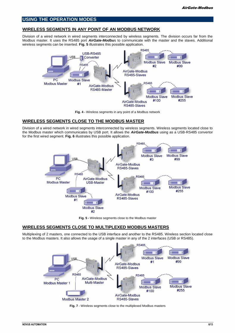
WIRELESS SEGMENTS IN ANY POINT OF AN MODBUS NETWORK
Division of a wired network in wired segments interconnected by wireless segments. The division occurs far from the Modbus master. It uses the RS485 port AirGate-Modbus to communicate with the master and the slaves. Additional wireless segments can be inserted. Fig. 5 illustrates this possible application.
Fig. 4 - Wireless segments in any point of a Modbus network
WIRELESS SEGMENTS CLOSE TO THE MODBUS MASTER
Division of a wired network in wired segments interconnected by wireless segments. Wireless segments located close to the Modbus master which communicates by USB port. It allows the AirGate-Modbus using as a USB-RS485 convertor for the first wired segment. Fig. 6 illustrates this possible application.
Fig. 5 - Wireless segments close to the Modbus master
WIRELESS SEGMENTS CLOSE TO MULTIPLEXED MODBUS MASTERS
Multiplexing of 2 masters, one connected to the USB interface and another to the RS485. Wireless section located close to the Modbus masters. It also allows the usage of a single master in any of the 2 interfaces (USB or RS485).
Fig. 7 - Wireless segments close to the multiplexed Modbus masters
AirGate-Modbus
NOVUS AUTOMATION 7/13
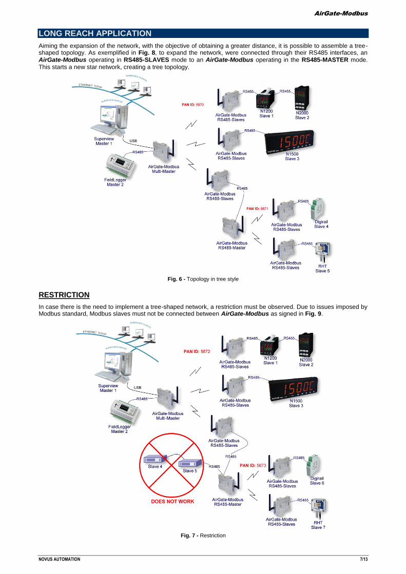
LONG REACH APPLICATION
Aiming the expansion of the network, with the objective of obtaining a greater distance, it is possible to assemble a tree-shaped topology. As exemplified in Fig. 8, to expand the network, were connected through their RS485 interfaces, an AirGate-Modbus operating in RS485-SLAVES mode to an AirGate-Modbus operating in the RS485-MASTER mode.
This starts a new star network, creating a tree topology.
Fig. 6 - Topology in tree style
RESTRICTION
In case there is the need to implement a tree-shaped network, a restriction must be observed. Due to issues imposed by Modbus standard, Modbus slaves must not be connected between AirGate-Modbus as signed in Fig. 9.
Fig. 7 - Restriction
AirGate-Modbus
NOVUS AUTOMATION 8/13
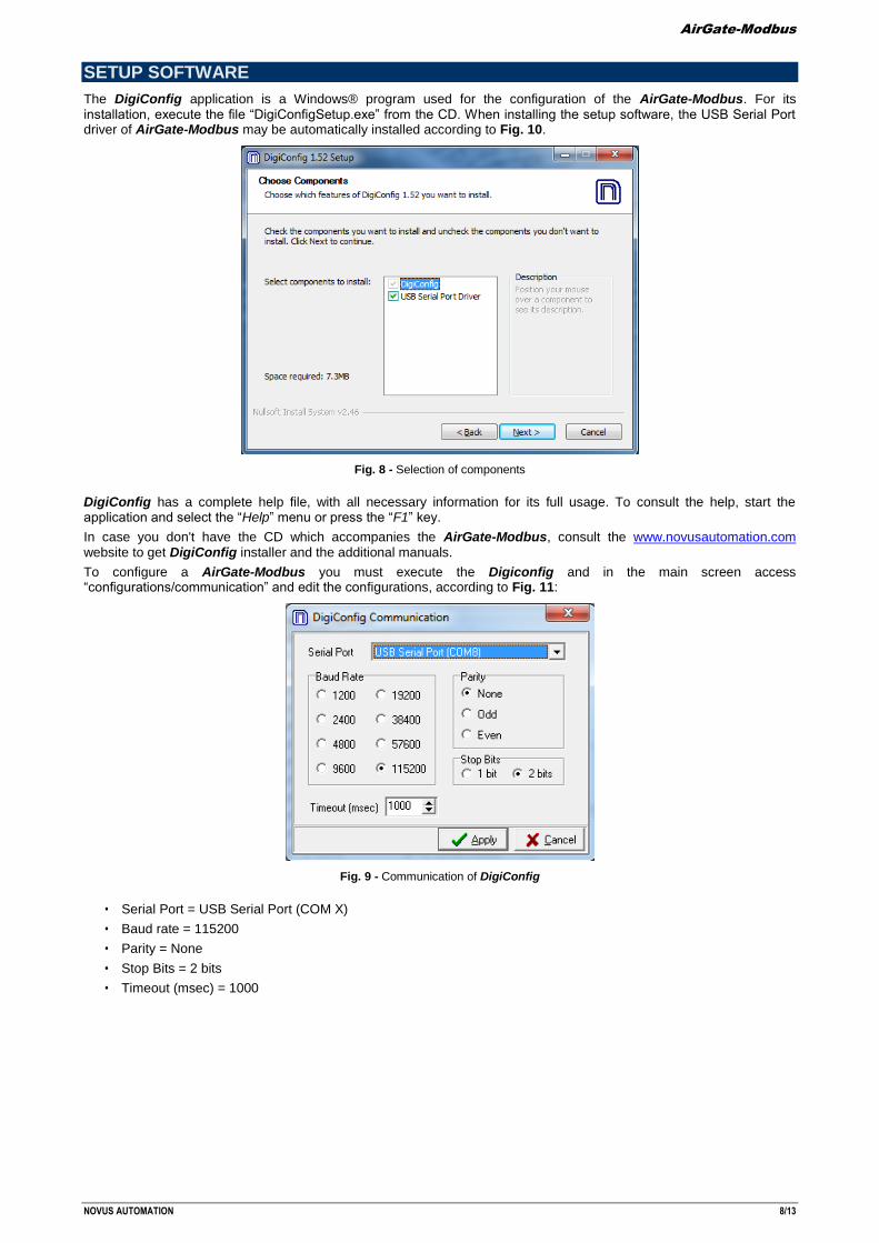
SETUP SOFTWARE
The DigiConfig application is a Windows® program used for the configuration of the AirGate-Modbus. For its installation, execute the file “DigiConfigSetup.exe” from the CD. When installing the setup software, the USB Serial Port driver of AirGate-Modbus may be automatically installed according to Fig. 10.
Fig. 8 - Selection of components
DigiConfig has a complete help file, with all necessary information for its full usage. To consult the help, start the application and select the “Help” menu or press the “F1” key.
In case you don't have the CD which accompanies the AirGate-Modbus, consult the www.novusautomation.com website to get DigiConfig installer and the additional manuals.
To configure a AirGate-Modbus you must execute the Digiconfig and in the main screen access “configurations/communication” and edit the configurations, according to Fig. 11:
Fig. 9 - Communication of DigiConfig
• Serial Port = USB Serial Port (COM X)
• Baud rate = 115200
• Parity = None
• Stop Bits = 2 bits
• Timeout (msec) = 1000
AirGate-Modbus
NOVUS AUTOMATION 9/13
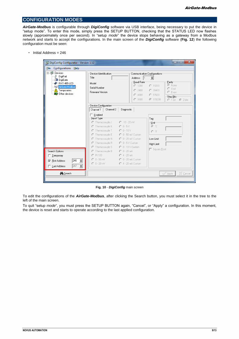
CONFIGURATION MODES
AirGate-Modbus is configurable through DigiConfig software via USB interface, being necessary to put the device in “setup mode”. To enter this mode, simply press the SETUP BUTTON, checking that the STATUS LED now flashes slowly (approximately once per second). In “setup mode” the device stops behaving as a gateway from a Modbus network and starts to accept the configurations. In the main screen of the DigiConfig software (Fig. 12) the following
configuration must be seen:
• Initial Address = 246
Fig. 10 - DigiConfig main screen
To edit the configurations of the AirGate-Modbus, after clicking the Search button, you must select it in the tree to the left of the main screen.
To quit “setup mode“, you must press the SETUP BUTTON again, “Cancel”, or “Apply” a configuration. In this moment,
the device is reset and starts to operate according to the last applied configuration.
AirGate-Modbus
NOVUS AUTOMATION 10/13
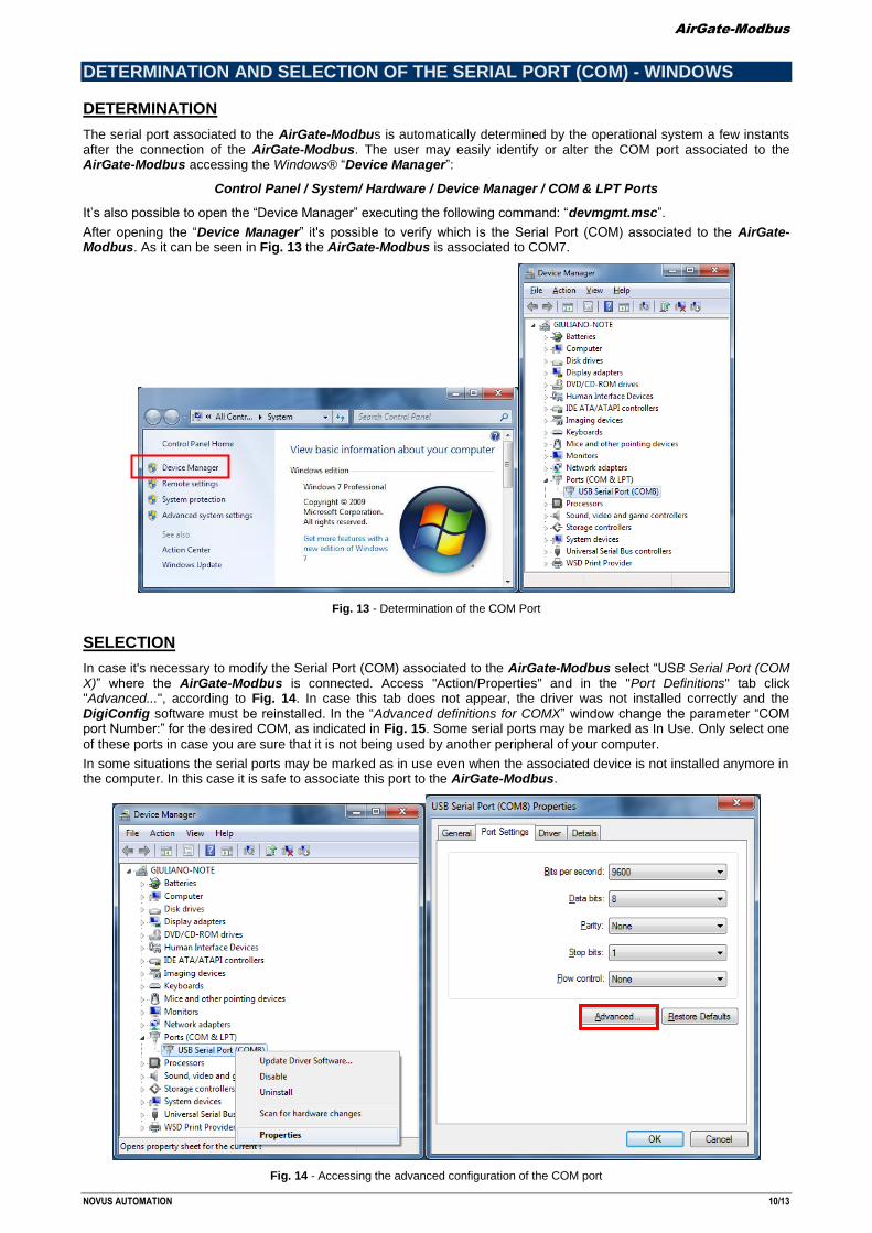
DETERMINATION AND SELECTION OF THE SERIAL PORT (COM) - WINDOWS
DETERMINATION
The serial port associated to the AirGate-Modbus is automatically determined by the operational system a few instants after the connection of the AirGate-Modbus. The user may easily identify or alter the COM port associated to the AirGate-Modbus accessing the Windows® “Device Manager”:
Control Panel / System/ Hardware / Device Manager / COM & LPT Ports
It’s also possible to open the “Device Manager” executing the following command: “devmgmt.msc”.
After opening the “Device Manager” it's possible to verify which is the Serial Port (COM) associated to the AirGate-Modbus. As it can be seen in Fig. 13 the AirGate-Modbus is associated to COM7.
Fig. 13 - Determination of the COM Port
SELECTION
In case it's necessary to modify the Serial Port (COM) associated to the AirGate-Modbus select “USB Serial Port (COM X)” where the AirGate-Modbus is connected. Access "Action/Properties" and in the "Port Definitions" tab click "Advanced...", according to Fig. 14. In case this tab does not appear, the driver was not installed correctly and the DigiConfig software must be reinstalled. In the “Advanced definitions for COMX” window change the parameter “COM port Number:” for the desired COM, as indicated in Fig. 15. Some serial ports may be marked as In Use. Only select one
of these ports in case you are sure that it is not being used by another peripheral of your computer.
In some situations the serial ports may be marked as in use even when the associated device is not installed anymore in the computer. In this case it is safe to associate this port to the AirGate-Modbus.
Fig. 14 - Accessing the advanced configuration of the COM port
AirGate-Modbus
NOVUS AUTOMATION 11/13
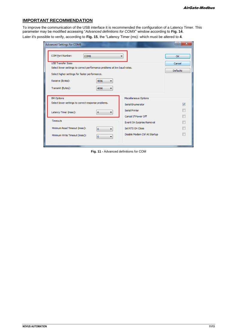
IMPORTANT RECOMMENDATION
To improve the communication of the USB interface it is recommended the configuration of a Latency Timer. This parameter may be modified accessing “Advanced definitions for COMX” window according to Fig. 14.
Later it's possible to verify, according to Fig. 15, the “Latency Timer (ms): which must be altered to 4.
Fig. 11 - Advanced definitions for COM
AirGate-Modbus
NOVUS AUTOMATION 12/13
CONFIGURATIONS - AIRGATE-MODBUS
BASICS
PAN ID
Choose a common identifier for each wireless network. All of the AirGate-Modbus devices from a same network must be configured with the same PAN ID.
BAUD RATE
Select for each interface the baud rate used by the Modbus network. All of the devices from the network must be configured with the same baud rate.
PARITY
Select for each interface the parity/stop bits used by the Modbus network. All of the network devices must be configured with the same parity/stop bits.
TIMEOUT
Timeout (in milliseconds) for the receipt of response bytes to the command sent to the slave station. Calculated automatically by the software, according to the select baud rate.
For RS485-Master, RS485-Slaves and USB-Master operation modes, this parameter is only shown in the screen to help the setup of the network master's Timeout, which must have its Timeout time configured with at least the Timeout shown in DigiConfig screen.
For Multi-Master operation mode, this parameter is used by the AirGate-Modbus, and may have its Timeout altered by the DigiConfig according to what is explained in the section “MULTI-MASTER” of the “OPERATION MODES” chapter. Noting that in this case the Timeout configured in each network master must be at least double the time configured for AirGate-Modbus.
OPERATION MODES
According to the desired functionality the AirGate-Modbus can be configured with different operation modes. These are
distinguished altering the functions of the communication interfaces, as explained in the “OPERATION MODES” chapter. When selecting a operation mode in DigiConfig, a figure containing a topology example will help in its setup.
ADVANCED
INTERFRAME TIME
The maximum time allowed (in microseconds) between the receipt of two bytes from a same package. This time is calculated automatically by DigiConfig software. It must only be modified it any of the network slaves show a high communication error rate. The "Minimum time” and "Maximum Time" values are shown in DigiConfig and range according to the lowest baud rate selected for the interfaces in the “Basic Configurations Guide”. When clicking the “Auto” button the text box will be available for altering of the "Interframe Time” which must obligatorily be within the band.
RF POTENCY
Alters the value of the transmission potency of the AirGate-Modbus. Valid values from 0 to 20 dBm.
SECURITY
The encryption of the packages may be enabled by selecting the “Enable Security” box. In case you wish to modify the security key simply click “Change Security Key” and type a new key in the fields “Typethekeyhere”.
FIRMWARE UPDATE
This DigiConfig tab is used for the firmware update of the AirGate-Modbus.
The following steps must be followed:
1. Locate the "Firmware" tab "Device Setup”.
2. Select "Enable Firmware Update”.
3. Click "Open” and search the new firmware file (".cbin").
4. Press the “Apply” button.
5. Wait the Firmware update process conclusion. The DigiConfig will show a text box with the information AirGate-Modbus firmware recording performed successfully. Click "OK".
6. The DigiConfig will turn back to the initial screen and the STATUS LED of the AirGate-Modbus will start to flash rapidly.
During the Firmware update process of the AirGate-Modbus, there must not have any interruption. In case there is power outage, disconnection of the USB cable or interruption of the Digiconfig software during the process, the AirGate-Modbus will probably cease operating normally and must be forwarded to the technical support of the supplier.
AirGate-Modbus
NOVUS AUTOMATION 13/13
DATA COMMUNICATION - SERIAL
The AirGate-Modbus possesses two communication interfaces:
• RS485, acting as communication interface with Modbus RTU protocol.
• USB device, acting with the communication interface of Modbus RTU protocol.
RS485 AND USB INTERFACE
The RS485 and USB interfaces may be configured to operate in the following speeds (baud rates): 1200, 2400, 4800, 9600, 19200, 38400, 57600 and 115200. Besides that, it may be configured to operate with one or two stop bits, and in the parities even, uneven and none.
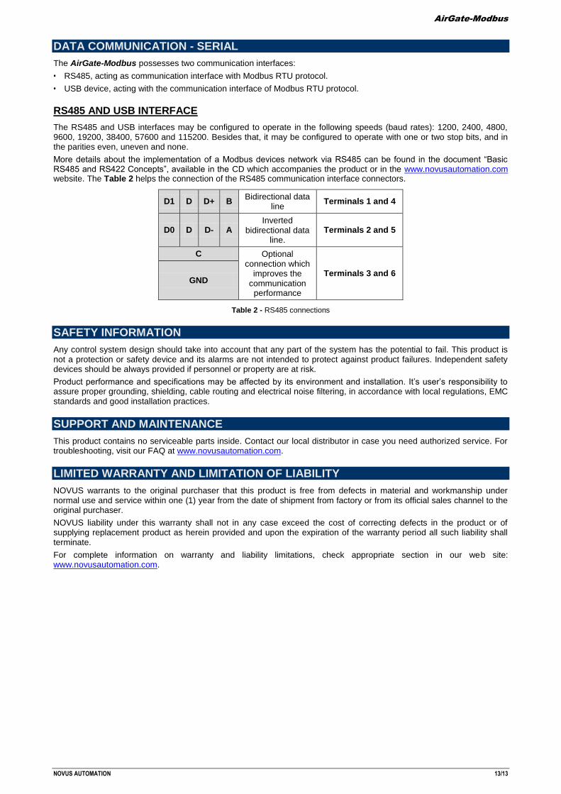
More details about the implementation of a Modbus devices network via RS485 can be found in the document “Basic RS485 and RS422 Concepts”, available in the CD which accompanies the product or in the www.novusautomation.com website. The Table 2 helps the connection of the RS485 communication interface connectors.
D1 D D+ B Bidirectional data
line Terminals 1 and 4
D0 D D- A Inverted
bidirectional data line.
Terminals 2 and 5
C Optional connection which
improves the communication
performance
Terminals 3 and 6 GND
Table 2 - RS485 connections
SAFETY INFORMATION
Any control system design should take into account that any part of the system has the potential to fail. This product is not a protection or safety device and its alarms are not intended to protect against product failures. Independent safety devices should be always provided if personnel or property are at risk.
Product performance and specifications may be affected by its environment and installation. It’s user’s responsibility to assure proper grounding, shielding, cable routing and electrical noise filtering, in accordance with local regulations, EMC standards and good installation practices.
SUPPORT AND MAINTENANCE
This product contains no serviceable parts inside. Contact our local distributor in case you need authorized service. For troubleshooting, visit our FAQ at www.novusautomation.com.
LIMITED WARRANTY AND LIMITATION OF LIABILITY
NOVUS warrants to the original purchaser that this product is free from defects in material and workmanship under normal use and service within one (1) year from the date of shipment from factory or from its official sales channel to the original purchaser.
NOVUS liability under this warranty shall not in any case exceed the cost of correcting defects in the product or of supplying replacement product as herein provided and upon the expiration of the warranty period all such liability shall terminate.
For complete information on warranty and liability limitations, check appropriate section in our web site: www.novusautomation.com.