Aircraft Trajectory Modeling and Alerting Algorithm ...mln/ltrs-pdfs/icase-2000-16.pdfAircraft...
21
National Aeronautics and Space Administration Langley Research Center Hampton, Virginia 23681-2199 NASA/CR-2000-210097 ICASE Report No. 2000-16 Aircraft Trajectory Modeling and Alerting Algorithm Verification César Muñoz ICASE, Hampton, Virginia Victor Carreño NASA Langley Research Center, Hampton, Virginia Institute for Computer Applications in Science and Engineering NASA Langley Research Center Hampton, VA Operated by Universities Space Research Association April 2000 Prepared for Langley Research Center under Contract NAS1-97046
-
Upload
nguyendang -
Category
Documents
-
view
224 -
download
3
Transcript of Aircraft Trajectory Modeling and Alerting Algorithm ...mln/ltrs-pdfs/icase-2000-16.pdfAircraft...

National Aeronautics andSpace Administration
Langley Research CenterHampton, Virginia 23681-2199
NASA/CR-2000-210097ICASE Report No. 2000-16
Aircraft Trajectory Modeling and Alerting AlgorithmVerification
César MuñozICASE, Hampton, Virginia
Victor CarreñoNASA Langley Research Center, Hampton, Virginia
Institute for Computer Applications in Science and EngineeringNASA Langley Research CenterHampton, VA
Operated by Universities Space Research Association
April 2000
Prepared for Langley Research Centerunder Contract NAS1-97046

AIRCRAFT TRAJECTORY MODELING AND ALERTING ALGORITHM
VERIFICATION�
C�ESAR MU~NOZy AND VICTOR CARRE~NOz
Abstract. The Airborne Information for Lateral Spacing (AILS) program at NASA Langley Research
Center aims at giving pilots the information necessary to make independent approaches to parallel runways
with spacing down to 2500 feet in Instrument Meteorological Conditions. The AILS concept consists of
accurate tra�c information visible at the navigation display and an alerting algorithm which warns the
crew when one of the aircraft involved in a parallel landing is diverting from the intended ight path. In
this paper we present a model of aircraft approaches to parallel runways. Based on this model, we analyze
the alerting algorithm with the objective of verifying its correctness. The formalization is conducted in the
general veri�cation system PVS.
Key words. trajectory modeling, alerting algorithm, formal methods, theorem proving
Subject classi�cation. Computer Science
1. Introduction. The Airborne Information for Lateral Spacing (AILS) [12, 3, 6] is a project being
conducted at NASA Langley Research Center. Its objective is to reduce tra�c delays and increase airport
e�ciency by enabling approaches to closely spaced parallel runways in Instrument Meteorological Conditions.
Approaches to parallel runways are currently limited to 4300 feet in Instrument Meteorological Condi-
tions. Specially equipped airports with fast scan radars, high resolution monitoring systems, and approach-
speci�c air tra�c controllers can perform parallel approaches to 3400 feet [14, 8]. The AILS project aims at
shifting the responsibility of maintaining separation during parallel approaches from the air tra�c controller
to the aircraft crew. Via the AILS concept, approaches to parallel runways 2500 feet apart in Instrument
Meteorological Conditions are expected.
AILS eliminates the delay inherent in the communication between air tra�c controller and crew by
displaying parallel tra�c information in the cockpit. The degree of safety is enhanced by an alerting system
which warns the crew when one of the aircraft involved in a parallel landing is deviating from the intended
ight path. The alerting algorithm is a critical part of the AILS concept. Flaws in its logic could lead to
non-alerted collision incidents. The algorithm has been extensively tested in simulators and in real ights.
The objective of this work is to conduct a formal analysis of the alerting algorithm in order to discover
any possible errors that have not been detected during testing and simulation. In particular, we develop a
formal model of parallel landing scenarios. Based on this model, we study the behavior of the AILS algorithm
with respect to predictions of collision incidents.
The formalization presented in this paper has been developed in the general veri�cation system PVS
[11]. We use a stylized-LATEX PVS concrete syntax and assume the reader is familiar with standard notations
of higher-order logic.
�This work was supported by the National Aeronautics and Space Administration under NASA Contract No. NAS1-97046
while the �rst author was in residence at the Institute for Computer Applications in Science and Engineering (ICASE), NASA
Langley Research Center, Hampton, VA 23681-2199, USA.yInstitute for Computer Applications in Science and Engineering (ICASE), Mail Stop 132C, NASA Langley Research Center,
Hampton, VA 23681-2199, USA, e-mail: [email protected] Technology Branch, Mail Stop 130, NASA Langley Research Center, Hampton, VA 23681-2199, USA, e-mail:
1

Table 2.1
Alerting sequence
Evader Intruder
1 Localizer alert (one dot deviation)
2 Localizer alert (two dot deviation)
3 Caution alert (tra�c)
4 Caution alert (tra�c)
5 Warning alert (collision)
6 Warning alert (collision)
The remainder of this paper is organized as follows. Section 2 gives an overview of the AILS system.
Section 3 describes the alerting algorithm and its abstraction in PVS. A formal model of aircraft trajectories
is presented in Section 4. Section 5 contains the main properties that have been proven in PVS. Section 6
summarizes our work and suggests future research directions. Finally, the appendix includes our PVS formal
model which is electronically available at: http://shemesh.larc.nasa.gov/people/vac/ails.pvs.
2. System Description. In a typical independent parallel approach, aircraft intersect their localizer
track (longitudinal runway center) approximately 10 nautical miles from the runway threshold (see Fig-
ure 2.1). During localizer intersection, aircraft have a 1000 feet vertical separation. After the aircraft are
established in their localizer track, vertical separation is eliminated and aircraft start a normal glide path for
landing. If an aircraft deviates from its airspace, the AILS system provides 6 alert levels, depending on the
severity of the deviation. Table 2.1 shows an alerting sequence as seen in the evader and intruder aircraft
primary and navigation displays.
All alerts in the intruder aircraft are expected to be followed by a corrective maneuver. The evader
aircraft is not expected to perform an evasive maneuver until a warning alert is issued, at which time landing
is aborted and an emergency escape maneuver is performed. Notice that the intruder aircraft always receives
a caution or warning alert before the respective caution or warning alerts are issued to the evader. A parallel
runway approach is illustrated in Figure 2.1.
Several assumptions were made in the development of the alerting algorithm. These assumptions are
justi�ed by physical characteristics and operational constraints. They are as follows:
� Time is discrete and divided in increments of 0.5 seconds. We call this value tstep.
� The algorithm is executed every tstep seconds.
� The rate of turn is determined by the bank angle and ground speed.
� The speeds of the aircraft are constant. Henceforth, we use intruderSpeed and evaderSpeed as
the constant speed values of the intruder and evader aircraft, respectively.
� The AILS system starts operating when the aircraft are on their localizers. At this time the aircraft
are approximately at the same altitude.
� The vertical separation between the aircraft is assumed to be 0 during a landing approach.
� Only the intruder aircraft will deviate from its path in a parallel approach. The evader aircraft stays
in its localizer.
It should be noted that the experimental AILS system, as currently designed, forms part of the Tra�c
Alert and Collision Avoidance System (TCAS) [13]. In this work, we assume that the AILS alerting algorithm
is running in isolation from other aircraft components. In addition, we concentrate on the caution and
2

x
y
Two Dot Deviation
One Dot DeviationLocalizer Track
wdist
cdist
10 NM
Fig. 2.1. Parallel runway approach
warning alerting kernel of the AILS alerting system. The one dot and two dot deviation alerts present a
simple scenario and can be easily added to our model by a separate function as it is done in the current
implementation.
3. The AILS Alerting Algorithm. The alerting algorithm determines when an alarm will be trig-
gered by calculating possible collision trajectories and comparing the future aircraft locations with predeter-
mined time and distance thresholds. The algorithm is executed in two modes every tstep seconds: (1) the
�rst mode assumes its own aircraft is a threat to the adjacent aircraft and the adjacent aircraft is following
the localizer; (2) the second mode assumes the adjacent aircraft is a threat to its own and the own is following
the localizer. In either mode, one aircraft is the intruder and one is the evader.
When the intruder aircraft is not changing direction, i.e., its bank angle is 0, the algorithm determines
if the two aircraft are diverging or converging and the point of closest separation. This is done by obtaining
the derivative of the distance between the aircraft and solving for time when the derivative equals zero as
follows.
�x(t) = xin(t)� xev(t)(3.1)
�y(t) = yin(t)� yev(t)(3.2)
d
dt�x(t) = intruderSpeed � cos(�)� evaderSpeed(3.3)
d
dt�y(t) = intruderSpeed � sin(�)(3.4)
R(t) =
q�x(t)
2 +�y(t)2(3.5)
d
dtR(t) =
�x(t)�ddt�x(t) +�y(t)�
ddt�y(t)p
R(t)(3.6)
For a time t, (xin(t); yin(t)) and (xev(t); yev(t)) are the coordinates of the intruder and evader aircraft,
respectively, and � is the heading angle of the intruder aircraft. When d
dtR(t + �) = 0, we get the time � ,
relative to t, of the point of closest separation of the aircraft. Time � has been calculated as
�(t) = ��x(t)�
ddt�x(t) +�y(t)�
ddt�y(t)
ddt�x(t)2 +
ddt�y(t)2
(3.7)
3

Timetau
Closest separation R(t
)
Dis
tanc
e
Fig. 3.1. Converging tracks
TangentTracks
1.5 to 3 degrees
circulararc pathat currentbank angle
Fig. 3.2. Radial trajectory and tangential tracks
Equations 3.1 to 3.7 were formally deduced, from initial physical properties, by using the computer
algebra tool MuPAD [4]. Notice that � is undetermined when the aircraft are parallel and the ground speeds
are equal. In this case, the alerting algorithm de�nes �(t) = 0 for any t.
For a time t, if �(t) is negative or zero, the tracks are diverging or parallel, respectively. If �(t) is greater
than zero, the tracks are converging and �(t) will be the time of closest separation (Figure 3.1). When tracks
are diverging or parallel, the algorithm checks the aircraft separation at the present time against the alert
threshold distances (cdist and wdist in Figure 2.1). When tracks are converging, the algorithm compares
the time and distance of closest separation against time and distance thresholds, respectively.
When the intruder aircraft is changing direction, i.e., its bank angle is not 0, the algorithm calculates
the radius of the turn and the rate of change of direction. Tangential tracks are calculated from the arc path
as to produce tangents which are 1.5� to 3� in angular separation (Figure 3.2). For each of these tangential
tracks the algorithm determines whether the two aircraft tracks are diverging or converging and performs
time and distance comparisons as explained above.
The original AILS algorithm was written in FORTRAN at Langley Research Center. It has been revised
several times and the latest version own in the Boeing 757 experimental aircraft was provided by Honeywell.
For the work presented in this paper, we created a high level abstract model of the alerting algorithm in
the PVS language. The algorithm model uses the same strategy as the FORTRAN algorithm to determine
if alarms are triggered, as explained above. All of the PVS declarations involved in the modeling of the
algorithm can be seen in the theory �le available at http://shemesh.larc.nasa.gov/people/vac/ails.
pvs.
The model of the algorithm is a function which takes the states of the aircraft and returns a boolean
4

value corresponding to whether the alarm is triggered or not. The type of the alarm, caution or warning,
depends on the threshold parameters. The state of the aircraft is de�ned by a record:
state : TYPE =
[# x : real,
y : real,
heading : [-180...180]
phi : [-45...45]
#]
We recall that access to records are written in PVS as function calls, i.e., if s is a state, x(s) refers
to the �eld x of the state s. Thus, x(s) and y(s) are the position coordinates, heading(s) is the angle
between the ight path and the localizer track which range between �180� and 180�, and phi(s) is the
aircraft bank angle between �45� and 45�.
The model of the alerting algorithm is given next.
larcalert(evader,intruder:state): bool =
LET phi = phi(intruder) IN
LET trkrate = g�(180/�)�tand(phi)/intruderSpeed IN
IF trkrate = 0 THEN % Direction is not changing.
chktrack(0) % Check strait tracks.
ELSE % Direction is changing
LET arcrad = % Calculate arc radius.
intruderSpeed2/(g�tand(phi)) IN
LET maxstep = alert_time/tstep IN
LET idtrk =
IF abs(trkrate) � 3 THEN 1 % This determines
ELSIF abs(trkrate) � 1+1/2 THEN 2 % how often
ELSIF abs(trkrate) � 3/4 THEN 4 % tangential
ELSE 8 % tracks are
ENDIF IN % calculated.
arc_loop(evader,intruder,arcrad,trkrate,idtrk,0,maxstep)
ENDIF
where g is the gravitational acceleration constant (approx. 32:2 feet/seconds2).
The �rst part of the function is exercised when the track rate (trkrate) is zero and there is no change
in the intruder's heading. The chktrack function is used to determine if an alarm will be triggered. The
function chktrack makes the calculation for converging or diverging tracks, according to Equations 3.1
to 3.7. If the tracks are diverging, the function chkrange is called to compare present locations against time
and distance threshold (ctime and cdist, respectively). If the tracks are converging, predicted locations at
caution time or time of closest separation, whatever is smaller, are compared. The structure of the de�nitions
of chkrange and chktrack are given next.
chkrange(range,t:real): bool =
range � cdist ^ t � ctime
chktrack(t:real): bool =
LET range = R(t) IN
5

LET tau = �(t) IN
IF tau � 0 THEN % Tracks are diverging (or parallel).
chkrange(range,t) % Check range at prediction time t.
ELSE % Tracks are converging.
IF t+tau > ctime THEN % Closest separation beyond caution alert time.
R(ctime) � cdist % Check range at caution threshold.
ELSE % Closest separation within caution alert time.
R(t+tau) � cdist % Check range at time of closest separation.
ENDIF
ENDIF
The second part of the function larcalert handles the case when intruder is changing direction. The arc
radius is calculated and the function arc loop generates the tangential tracks from the arc trajectory. The
function arc loop is a recursive function modeling a DO-LOOP statement. It is used to iterate the function
chktrack on tangential tracks every idtrk time steps. Its actual de�nition is too long to be included in the
paper and can also be seen in the theory �le as pointed above. The structure of the function is:
arc_loop(evader,intruder,arcrad,trkrate,idtrk,iarc,maxstep): RECURSIVE bool =
calculate positions of aircraft
IF not time for a tangential track THEN
IF chkrange(...) THEN % Check range at that point.
TRUE % Trigger an alarm.
ELSE
arc_loop(...) % Go to new iteration.
ENDIF
ELSE % Time for tangential tracks.
IF chktrk(...) THEN % Check track at this point.
TRUE % Trigger an alarm.
ELSE
arc_loop(...) % Go to new iteration.
ENDIF
ENDIF
Based on the idtrk argument and the step in the loop iarc, the function arc loop determines if a
tangential track is calculated or not. If a tangential track is not calculated, the function chkrange compares
the distance between the calculated positions of the aircraft and the distance threshold. The function chktrk
is used to check for collisions on all the tangential tracks in the loop. The function arc loop terminates
when one of the functions chkrange or chktrack triggers an alarm or when iarc has reached maxstep.
In the PVS model, we are using an axiomatic de�nition of the square root function (sqrt, see Section
5). Trigonometric functions (sind, cosd, and tand, for sine, cosine, and tangent of angles in degrees,
respectively) are de�ned by series approximations. However, as we will see in Section 5, we also provide
axioms about trigonometric functions to facilitate the proofs.
As we have seen, the AILS algorithm considers a limited set of possible trajectories for the intruder
aircraft, i.e., assuming a constant radius turn at the original bank angle, only tangent track escapes to the
turn arc are considered. The developers of the algorithm state that this assumption is reasonable under
normal circumstances, i.e., the intruder aircraft is not intentionally trying to collide with the evader aircraft.
However, to evaluate the behavior of the algorithm in a wider range of possible landing scenarios, a more
6

general model of trajectories for the intruder aircraft is necessary. In the next section, we develop such a
model.
4. Parallel Landing Scenarios. According to the characteristics and assumptions of the AILS algo-
rithm, we propose a time-discrete model with time increments of tstep seconds.
In our model of trajectories, as in the case of the alerting algorithm, intrusion paths are determined by
the bank angle and ground speed of the intruder aircraft. Given a ground speed gs > 0, a bank angle �, the
heading turn rate is given by
trkrate(gs; �) =tand(�)� g � 180
gs� �;
where g is the gravitational acceleration constant.
Although under normal operation the bank angle of a commercial aircraft is limited to �30� to 30�, we
allow the bank angle to range from �45� to 45�. For a minimum ground speed of 180 feet per second, it
means a maximum heading turn rate of about 6� per second. These data produce very aggressive blundering
situations quite consistent with worst cases scenarios tested by the AILS developing group. Incidentally, the
function trkrate is well-de�ned for bank angles in the range [�45 : : :45].
Definition 4.1 (Intruder trajectory). An intruder trajectory of length n for an aircraft with state s
and ground speed gs is a sequence of states s0 : : : sn such that s0 = s and for 0 < i � n,
1. jphi(si)j � 45,
2. jheading(si)� heading(si�1)j = tstep� trkrate(gs; phi(si)),
3. x(si) = x(si�1) + gs� tstep� cosd(heading(si)), and
4. y(si) = y(si�1) + gs� tstep� sind(heading(si)).
In PVS, we de�ne the next state of an intruder aircraft at state s and bank angle � by the function
next_intruder_state(s:state,�:[-45...45]): state =
LET trk = heading(s) + tstep�trkrate(intruderSpeed,phi(s)) IN
s WITH [
x := x(s) + intruderSpeed�tstep�cosd(trk),
y := y(s) + intruderSpeed�tstep�sind(trk),
heading := trk,
phi := �
]
We recall that WITH is the record (and function) overriding operator in PVS.
We model an intruder trajectory by a recursive function having as parameters an initial state s, a bank
angle assignation for each iteration step df, and the iteration step n, as follows
intruder_trajectory(s:state, df:[posnat![-45...45]], n:nat):
RECURSIVE state =
IF n = 0 THEN s
ELSE
LET sn = next_intruder_state(s, df(n)) IN
intruder_trajectory(sn,df,n-1)
ENDIF
MEASURE n
7

For example, given an intruder aircraft at initial state s and bank angle equal to 0, a trajectory of length
n such that the plane follows a straight line to its current heading angle is given by s0 : : : sn, where s0 = s
and for 0 < i � n,
si = intruder trajectory(s; �(n : posnat) : 0; i):
For the evader aircraft, we assume that it stays in its localizer with a constant speed and constant
heading of 0�. Heading and bank angles are irrelevant in the de�nition of an evader trajectory.
Definition 4.2 (Evader trajectory). An evader trajectory of length n for an aircraft with state s and
ground speed gs is a sequence of states s0 : : : sn such that s0 = s and for 0 < i � n,
1. x(si) = x(si�1) + gs� tstep and
2. y(si) = y(s0).
For an initial state s of an aircraft, its state after n steps in a evader trajectory is de�ned by evader trajectory(s,n)
as follows
evader_trajectory(s:state, n:nat): state =
(#
x := x(s) + evaderSpeed�tstep�n,
y := y(s),
heading := heading(s),
phi := phi(s)
#)
We are interested in trajectories leading to collision incidents. Aircraft are said to be in collision if the
distance between them is less than or equal to collisionRange. In our development, we consider 200 feet
for collisionRange, which is approximately the wing span of a Boeing 747.
distance(s1,s2:state): real =
sqrt((x(s2)-x(s1))2 + (y(s2)-y(s1))2)
collision(s1,s2:state): bool =
distance(s1,s2) � collisionRange
Definition 4.3 (Collision scenario). Given an intruder trajectory s0 : : : sn and an an evader trajectory
t0 : : : tn, we said that they lead to a collision incident at step i, for 0 � i � n, if collision(si,ti) holds.
In PVS,
collision_scenario(intruder,evader:state, df:[posnat![-45...45]],
i:nat):bool =
collision(intruder_trajectory(intruder,df,i),
evader_trajectory(evader,i))
We have implemented the model of trajectories, together with our high-level version of the alerting
algorithm, in Java. The implementation, available in the same location as the PVS theory �les, serves a
double purpose. First, it allows us to visualize all the collision trajectories for a given time and initial values
of the intruder and evader aircraft. Second and more importantly, by studying those trajectories, we were
able to extract conjectures that we have then formally proven in PVS. Conversely, as we will mention later,
we have rejected some conjectures by �nding counter-examples via simulation of collision trajectories,
8
In the next section, we address the formal veri�cation of properties of collision trajectories for our model
in PVS, and we study the behavior of the alerting algorithm with respect to that model.
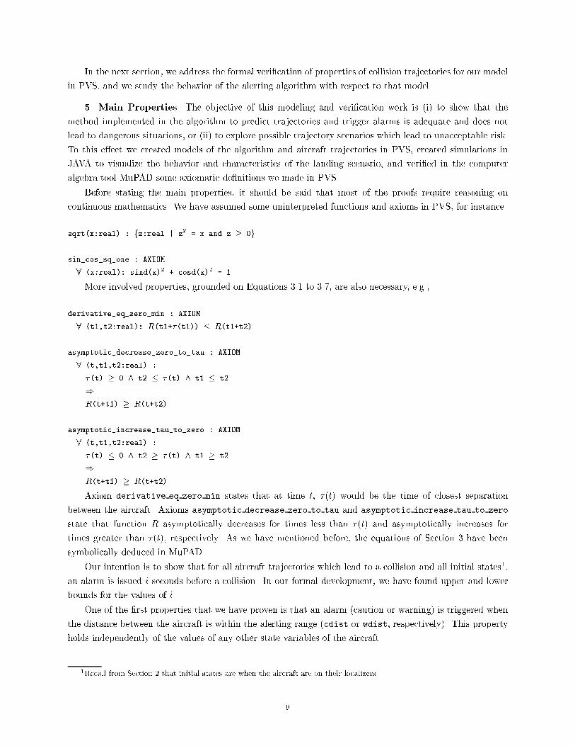
5. Main Properties. The objective of this modeling and veri�cation work is (i) to show that the
method implemented in the algorithm to predict trajectories and trigger alarms is adequate and does not
lead to dangerous situations, or (ii) to explore possible trajectory scenarios which lead to unacceptable risk.
To this e�ect we created models of the algorithm and aircraft trajectories in PVS, created simulations in
JAVA to visualize the behavior and characteristics of the landing scenario, and veri�ed in the computer
algebra tool MuPAD some axiomatic de�nitions we made in PVS.
Before stating the main properties, it should be said that most of the proofs require reasoning on
continuous mathematics. We have assumed some uninterpreted functions and axioms in PVS, for instance
sqrt(x:real) : fz:real | z2 = x and z � 0g
sin_cos_sq_one : AXIOM
8 (x:real): sind(x)2 + cosd(x)2 = 1
More involved properties, grounded on Equations 3.1 to 3.7, are also necessary, e.g.,
derivative_eq_zero_min : AXIOM
8 (t1,t2:real): R(t1+�(t1)) � R(t1+t2)
asymptotic_decrease_zero_to_tau : AXIOM
8 (t,t1,t2:real) :
�(t) � 0 ^ t2 � �(t) ^ t1 � t2
)
R(t+t1) � R(t+t2)
asymptotic_increase_tau_to_zero : AXIOM
8 (t,t1,t2:real) :
�(t) � 0 ^ t2 � �(t) ^ t1 � t2
)
R(t+t1) � R(t+t2)
Axiom derivative eq zero min states that at time t, �(t) would be the time of closest separation
between the aircraft. Axioms asymptotic decrease zero to tau and asymptotic increase tau to zero
state that function R asymptotically decreases for times less than �(t) and asymptotically increases for
times greater than �(t), respectively. As we have mentioned before, the equations of Section 3 have been
symbolically deduced in MuPAD.
Our intention is to show that for all aircraft trajectories which lead to a collision and all initial states1,
an alarm is issued i seconds before a collision. In our formal development, we have found upper and lower
bounds for the values of i.
One of the �rst properties that we have proven is that an alarm (caution or warning) is triggered when
the distance between the aircraft is within the alerting range (cdist or wdist, respectively). This property
holds independently of the values of any other state variables of the aircraft.
1Recall from Section 2 that initial states are when the aircraft are on their localizers.
9

alarm_when_alerting_distance : THEOREM
8 (evader,intruder:state) :
alerting_distance(evader,intruder) ) larcalert(evader,intruder)
The theorem above puts the greatest lower bound on the elapsed time between an alert and a collision
that we have found so far. For an alerting distance of 1400 feet and an intruder ground speed of 250 feet
per second this results in an alarm at least 4 seconds before collision.
An e�ort to prove that a caution is issued for a value of (ctime-1) (ctime being de�ned as 19 seconds)
resulted in an unprovable conjecture. Indeed, we have found a counter example of a collision trajectory
which allows two aircraft to y to a distance of less than 1300 feet, without triggering an alarm 11 seconds
before the collision.
move_2500_to_1300_no_alarm_before_11_seconds : THEOREM
9 (intruder,evader:state, df:[posnat![-45...45]], n:nat) :
collision_scenario(intruder,evader,df,n+11/tstep) ^
distance(indruder,evader) = 2500 ^
distance(intruder_trajectory(intruder,df,n),
evader_trajectory(evader,n)) < 1300 ^
8 (i:[0...n]):
: larcalert(evader_trajectory(evader,i),
intruder_trajectory(intruder,df,i))
By combining these theorems, we can state that for some trajectories an alarm will sound no more than
11 seconds before collision and that for all cases an alarm will sound at least 4 seconds before a collision. We
believe that for all cases the greatest-lower bound time when the alarm will sound prior to a collision is closer
to 11 than to 4. In order to reveal that bound, we need to �nd strong invariants on collision trajectories.
Notice, for example, that for an intruder trajectory s0 : : : sn and an evader trajectory t0 : : : tn, it cannot be
the case that they lead to a collision incident at step n when distance(s0,tn) > R, where
R = collisionRange+intruderSpeed�n�tstep:
Indeed, any intruder aircraft out of the circle of center (x(tn),y(tn)) and radius R, needs a larger time
than n�tstep to reach any point of the circle of center (x(tn),y(tn)) and radio collisionRange. The
property above can be expressed in PVS as follows.
collision_invariant : LEMMA
8 (intruder,evader:state, df:[posnat![-45...45]], n:nat) :
collision_scenario(intruder,evader,df,n)
)
8 (i:[0...n]):
distance(intruder_trajectory(intruder,df,i),
evader_trajectory(evader,n)) �
collisionRange+intruderSpeed�(n-i)�tstep
The proof of this invariant requires the following lemmas.
straight_line_farthest: LEMMA
8 (intruder:state,df:[posnat![-45...45],n:nat) :
LET straight_trajectory = �(n:posnat):0 IN
10

distance(intruder,
intruder_trajectory(intruder,df,n)) �
distance(intruder,
intruder_trajectory(intruder,straight_trajectory,n))
absolute_distance: LEMMA
8 (intruder:state,n:nat) :
phi(intruder)=0
)
LET straight_trajectory = �(n:posnat):0 IN
distance(intruder,
intruder_trajectory(intruder,straight_trajectory,n))
= intruderSpeed�n�tstep
Lemma straight line farthest states that an intruder trajectory following a straight lines reaches a point
farthest than any other trajectory, while Lemma absolute distance states that the length of an intruder
trajectory following a straight line is the same as intruderSpeed�n�tstep.
We intend to use the above invariant and lemmas, together with properties derived from the physical
trajectories, to �nd a bound greater than 4 seconds for any collision scenario. Under particular assumptions
of the intruder bank angle (given by the function df), we have proven that there exists a point outside of
the alerting threshold range where the alarm is issued. The conjecture is expressed in PVS as follows
bound : CONJECTURE
8 (intruder,evader:state, df:[posnat![-45...45]], n:nat) :
collision_scenario(intruder,evader,df,n)
)
9(i:[0...n]) :
: alerting_distance(evader_trajectory(evader,i),
intruder_trajectory(intruder,df,i)) ^
larcalert(evader_trajectory(evader,i),
intruder_trajectory(intruder,df,i))
We are trying to generalize the proof for an arbitrary value of df. If the attempt is successful, it gives a new
greatest lower bound of 5 seconds.
6. Conclusion. Several case studies have been performed on the application of hybrid automata to
the modeling of systems which include continuous and discrete domains. In particular, a simpli�ed TCAS
system was modeled in [9] using hybrid automata. That work focuses on establishing a hybrid model of the
closed loop system formed by several aircrafts ying under TCAS assumptions. Although it is claimed that
the model is suitable for formal analysis, there is no explicit attempt to automate the proof process. On the
other hand, state exploration techniques have been used to analyze the system requirements speci�cation of
TCAS II written in RSML [7]; we refer for instance to [5, 2]. These works focus on the reactive aspect of
the whole system.
In the work presented in this paper, we constructed a formal model of the kernel of an alerting algorithm
and we studied its behavior with respect to a model of collision trajectories. In our analysis, we assumed
that the alerting algorithm runs in isolation of the other components of the system. We defer the integration
of the alerting algorithm with rest of the system, for example TCAS, for future research.
An abstract model of the algorithm and its properties were developed in the general veri�cation system
11

PVS. We complemented the prover capabilities with computer algebra tools. Indeed, di�erential equations,
resulting from physical phenomena, were mechanically veri�ed in MuPAD. Models of the algorithm and
collision trajectories were implemented in Java. The implementation allowed us to explore collision scenarios
before performing rigorous attempts to prove properties.
Although we have con�dence in the conjectures that have been declared as axioms, work is being per-
formed [10] in the development of a PVS library on transcendental functions which complements a previous
work on mathematical analysis in PVS [1]. Hence, it might be possible in the near future to replace the
axiomatic de�nitions with theorems.
Lower and upper bounds for a time when an alarm will be issued before a collision were found. Our
immediate goal, in the veri�cation of the AILS algorithm, is to prove certain facts about the characteristics
of the aircraft trajectories. We hope that these facts allow us to prove the adequacy of the alerting algorithm
for a time large enough to avoid any possible collision incident.
REFERENCES
[1] B. Dutertre, Elements of mathematical analysis in PVS, in Ninth international Conference on Theo-
rem Proving in Higher Order Logics TPHOL, J. Von Wright, J. Grundy, and J. Harrison, eds.,
vol. 1125 of Lecture Notes in Computer Science, Turku, Finland, Aug. 1996, Springer Verlag,
pp. 141{156.
[2] W. Chan, R. Anderson, P. Beame, and D. Notkin, Improving e�ciency of symbolic model check-
ing for state-based system requirements, Technical Report TR-98-01-03, University of Washington,
Department of Computer Science and Engineering, Jan. 1998.
[3] T. Doyle and F. McGee, Air tra�c and operational data on selected u.s. airports with parallel
runways, Tech. Report NASA/CR-1998-207675, NASA, May 1998.
[4] B. Fuchssteiner et al., MuPAD User's Manual, John Wiley and Sons, Chichester, New York, �rst ed.,
Mar. 1996. Includes a CD for Apple Macintosh and UNIX.
[5] M. Heimdahl and N. Leveson, Completeness and Consistency Analysis of State-Based Requirements,
in Proceedings of the 17th International Conference on Software Engineering, Apr. 1995, pp. 3{14.
[6] S. Koczo, Coordinated parallel runway approaches, Tech. Report NASA-CR-201611, NASA, October
1996.
[7] N. Leveson, M. Heimdahl, H. Hildreth, and J. Reese, Requirements speci�cation for process-
control systems, Technical Report ICS-TR-92-106, University of California, Irvine, Department of
Information and Computer Science, Nov. 1992.
[8] A. Lind, Two simulation studies of precision runway monitoring of independent approaches to closely
spaced parallel runways, Tech. Report AD-A263433 ATC-190 DOT/FAA/NR-92/9, NASA, March
1993.
[9] J. Lygeros and N. A. Lynch, On the formal veri�cation of the TCAS con ict resolution algorithms,
in Proceedings 36th IEEE Conference on Decision and Control, San Diego, CA, Dec. 1997, pp. 1829{
1834. Extended abstract.
[10] U. Martin and H. Gottliebsen, Computational logic support for di�erential equations and mathe-
matical modeling. Personal communication, 2000.
[11] S. Owre, J. M. Rushby, and N. Shankar, PVS: A prototype veri�cation system, in 11th Interna-
tional Conference on Automated Deduction (CADE), D. Kapur, ed., vol. 607 of Lecture Notes in
12

Arti�cial Intelligence, Saratoga, NY, June 1992, Springer-Verlag, pp. 748{752.
[12] L. Rine, T. Abbott, G. Lohr, D. Elliott, M. Waller, and R. Perry, The ight deck perspective
of the NASA Langley AILS concept, Tech. Report NASA/TM-2000-209841, NASA, January 2000.
[13] RTCA, Minimum operational performance standards for tra�c alert and collision avoidance system
(TCAS) airborne equipment { consolidated edition, Guideline DO-185, Radio Technical Commission
for Aeronautics, One McPherson Square, 1425 K Street N.W., Suite 500, Washington DC 20005,
USA, 6 Sept. 1990.
[14] G. Wong, Development of precision runway monitor system for increasing capacity of parallel runway
operations, AGARD, Machine Intelligence in Air Tra�c Management, (1993), p. 12.
Appendix. The AILS Alerting Algorithm in PVS.
%----------------------------------------------------------------------------
% AILS Alerting Algorithm in PVS
% Victor Carreno ([email protected])
% Cesar Munoz ([email protected])
% ICASE - NASA Langley Research Center
% This model is an abstraction of the algorithm written by
% Bill Capron
% NASA Langley Research Center
% and described by
% Mike Jackson
% Honeywell Technology Center
% Assumptions
% * Coordinate system:
% +-->x --> landing direction
% |
% v
% y
% * Two dimensional
% * Ground speed is constant
%----------------------------------------------------------------------------
AILS : THEORY
BEGIN
%-- Types
Bank : TYPE = subrange(-45,45)
deg_heading : TYPE = subrange(-180,180)
State: type =
[# x : real,
y : real,
heading : deg_heading,
13

phi : Bank
#]
%-- Constants
collisionRange : real = 200
alertTime : real = 19
alertRange : real = 1000
intruderSpeed : real = 250
evaderSpeed : real = 250
tstep : real = 1/2
divtstep(x:real) : real = x*2
maxStep : real = 1 + divtstep(alertTime)
g : real = 32+2/10
%-- Variables
intruder,
evader : VAR State
df : VAR [posnat->Bank]
phi : VAR Bank
s,s1,s2 : VAR State
x,range : VAR real
t,t1,t2 : VAR real
n : VAR nat
m : VAR posnat
iarc : VAR subrange(0,maxStep)
arcrad,trkrate: VAR real
idtrk : VAR posnat
%-- Useful functions
pi : real = 3141592/1000000
cosd(x): real
= LET r = x*pi/180 IN
1 - expt(r,2)/2 + expt(r,4)/24 - expt(r,6)/720 + expt(r,8)/40320
sind(x) : real
= LET r = x*pi/180 IN
r - expt(r,3)/6 + expt(r,5)/120 - expt(r,7)/5040 + expt(r,9)/362880
tangent_well_defined : AXIOM
14

FORALL (phi) : cosd(phi) /= 0
tand(phi): real =
sind(phi)/cosd(phi)
mod(n,m): RECURSIVE nat =
IF n < m THEN n
ELSE mod(n-m,m)
ENDIF
MEASURE n
sq(x): nonneg_real = x*x
sqrt_well_defined : AXIOM
FORALL (x:nonneg_real):
nonempty?(fz:nonneg_real | z*z = xg)
sqrt(x:nonneg_real) : fz:nonneg_real | z*z = xg
distance(s1,s2): real =
sqrt(sq(x(s2)-x(s1)) + sq(y(s2)-y(s1)))
collision(s1,s2): bool =
distance(s1,s2) <= collisionRange
alerting_distance(s1,s2): bool =
distance(s1,s2) <= alertRange
trkrate(phi): real =
IF phi = 0 then 0
ELSE 1845*tand(phi)/intruderSpeed
ENDIF
dx(intruder,evader,t): real =
(x(intruder) + t*intruderSpeed*cosd(heading(intruder))) -
(x(evader) + t*evaderSpeed)
dy(intruder,evader,t): real =
(y(intruder) + t*intruderSpeed*sind(heading(intruder))) -
y(evader)
dxdt(intruder): real =
intruderSpeed*cosd(heading(intruder)) - evaderSpeed
15
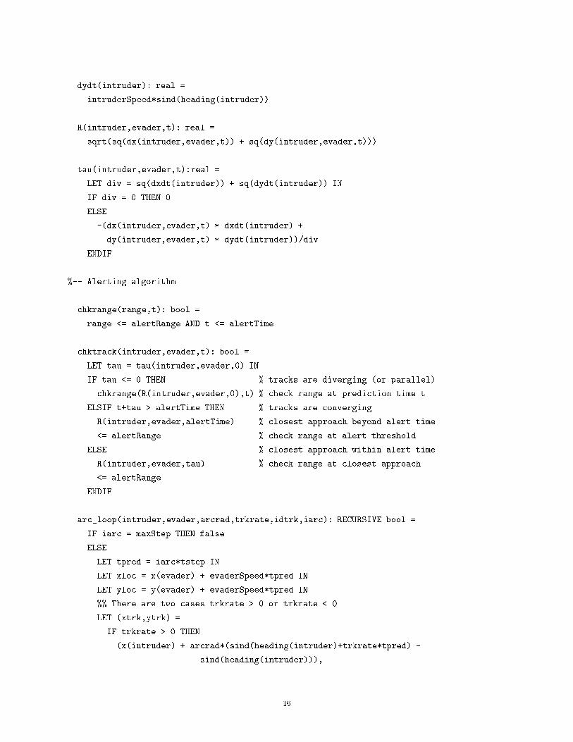
dydt(intruder): real =
intruderSpeed*sind(heading(intruder))
R(intruder,evader,t): real =
sqrt(sq(dx(intruder,evader,t)) + sq(dy(intruder,evader,t)))
tau(intruder,evader,t):real =
LET div = sq(dxdt(intruder)) + sq(dydt(intruder)) IN
IF div = 0 THEN 0
ELSE
-(dx(intruder,evader,t) * dxdt(intruder) +
dy(intruder,evader,t) * dydt(intruder))/div
ENDIF
%-- Alerting algorithm
chkrange(range,t): bool =
range <= alertRange AND t <= alertTime
chktrack(intruder,evader,t): bool =
LET tau = tau(intruder,evader,0) IN
IF tau <= 0 THEN % tracks are diverging (or parallel)
chkrange(R(intruder,evader,0),t) % check range at prediction time t
ELSIF t+tau > alertTime THEN % tracks are converging
R(intruder,evader,alertTime) % closest approach beyond alert time
<= alertRange % check range at alert threshold
ELSE % closest approach within alert time.
R(intruder,evader,tau) % check range at closest approach.
<= alertRange
ENDIF
arc_loop(intruder,evader,arcrad,trkrate,idtrk,iarc): RECURSIVE bool =
IF iarc = maxStep THEN false
ELSE
LET tpred = iarc*tstep IN
LET xloc = x(evader) + evaderSpeed*tpred IN
LET yloc = y(evader) + evaderSpeed*tpred IN
%% There are two cases trkrate > 0 or trkrate < 0
LET (xtrk,ytrk) =
IF trkrate > 0 THEN
(x(intruder) + arcrad*(sind(heading(intruder)+trkrate*tpred) -
sind(heading(intruder))),
16

y(intruder) + arcrad*(cosd(heading(intruder))-
cosd(heading(intruder)+trkrate*tpred)))
ELSE
(x(intruder) + arcrad*(sind(heading(intruder)) -
sind(heading(intruder))+trkrate*tpred),
y(intruder) + arcrad*(cosd(heading(intruder)+trkrate*tpred)-
cosd(heading(intruder))))
ENDIF IN
IF NOT mod(iarc,idtrk) = 0 THEN % not time for tangential track
LET range = sqrt(sq(xtrk-xloc) + sq(ytrk-yloc)) IN
IF chkrange(range,tpred) THEN true
ELSE arc_loop(intruder,evader,arcrad,trkrate,idtrk,iarc+1)
ENDIF
ELSE % tangential track
LET tantrk = heading(intruder) + tpred*trkrate IN
LET int = intruder WITH [x:=xtrk, y:=ytrk, heading:=tantrk] IN
LET eva = evader WITH [x:=xloc, y:=yloc] IN
IF chktrack(int,eva,tpred) THEN true
ELSE arc_loop(intruder,evader,arcrad,trkrate,idtrk,iarc+1)
ENDIF
ENDIF
ENDIF
MEASURE (maxStep - iarc)
larcalert(intruder,evader): bool =
LET phi = phi(intruder) IN
LET trkrate = trkrate(phi) IN
IF trkrate = 0 THEN
chktrack(intruder,evader,0)
ELSE
LET arcrad = sq(intruderSpeed)/(g*tand(phi)) IN
LET idtrk =
IF trkrate >= 3 THEN 1
ELSIF trkrate >= 1 + 1/2 THEN 2
ELSIF trkrate >= 3/4 THEN 4
ELSE 8
ENDIF IN
arc_loop(intruder,evader,arcrad,trkrate,idtrk,0)
ENDIF
%-- Model of trajectories
next_intruder_state(s,phi): State =
17

LET trk = heading(s) + tstep*trkrate(phi(s)) IN
s WITH [
x := x(s) + intruderSpeed*tstep*cosd(heading(s)),
y := y(s) + intruderSpeed*tstep*sind(heading(s)),
heading := trk,
phi := phi
]
intruder_trajectory(s,df,n): RECURSIVE State =
IF n = 0 THEN s
ELSE
next_intruder_state(intruder_trajectory(s, df, n-1),df(n))
ENDIF
MEASURE n
evader_trajectory(s,n): State =
(#
x := x(s) + evaderSpeed * tstep * n,
y := y(s),
heading := heading(s),
phi := phi(s)
#)
collision_scenario(intruder,evader,df,n): bool =
collision(intruder_trajectory(intruder,df,n),
evader_trajectory(evader,n))
%-- Axioms
sin_cos_sq_one : AXIOM
FORALL (x):
sq(sind(x)) + sq(cosd(x)) = 1
derivative_eq_zero_min : AXIOM
FORALL (intruder,t1,t2):
R(intruder,evader,t1+tau(intruder,evader,t1)) <=
R(intruder,evader,t1+t2)
asymptotic_decrease_zero_to_tau : AXIOM
FORALL (t,t1,t2:real) :
tau(intruder,evader,t) >= 0 AND t2 <= tau(intruder,evader,t) AND
t1 <= t2
IMPLIES
18
R(intruder,evader,t+t1) >= R(intruder,evader,t+t2)
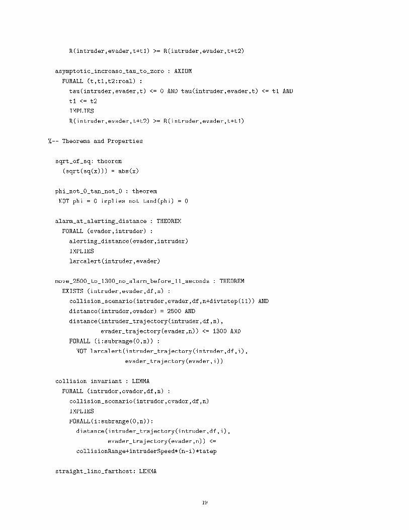
asymptotic_increase_tau_to_zero : AXIOM
FORALL (t,t1,t2:real) :
tau(intruder,evader,t) <= 0 AND tau(intruder,evader,t) <= t1 AND
t1 <= t2
IMPLIES
R(intruder,evader,t+t2) >= R(intruder,evader,t+t1)
%-- Theorems and Properties
sqrt_of_sq: theorem
(sqrt(sq(x))) = abs(x)
phi_not_0_tan_not_0 : theorem
NOT phi = 0 implies not tand(phi) = 0
alarm_at_alerting_distance : THEOREM
FORALL (evader,intruder) :
alerting_distance(evader,intruder)
IMPLIES
larcalert(intruder,evader)
move_2500_to_1300_no_alarm_before_11_seconds : THEOREM
EXISTS (intruder,evader,df,n) :
collision_scenario(intruder,evader,df,n+divtstep(11)) AND
distance(intruder,evader) = 2500 AND
distance(intruder_trajectory(intruder,df,n),
evader_trajectory(evader,n)) <= 1300 AND
FORALL (i:subrange(0,n)) :
NOT larcalert(intruder_trajectory(intruder,df,i),
evader_trajectory(evader,i))
collision_invariant : LEMMA
FORALL (intruder,evader,df,n) :
collision_scenario(intruder,evader,df,n)
IMPLIES
FORALL(i:subrange(0,n)):
distance(intruder_trajectory(intruder,df,i),
evader_trajectory(evader,n)) <=
collisionRange+intruderSpeed*(n-i)*tstep
straight_line_farthest: LEMMA
19

FORALL (intruder,evader,df,n) :
LET straight_trajectory = LAMBDA(n:posnat):0 IN
distance(intruder,
intruder_trajectory(intruder,df,n)) <=
distance(intruder,
intruder_trajectory(intruder,straight_trajectory,n))
absolute_distance: LEMMA
FORALL (intruder,n) :
phi(intruder)=0
IMPLIES
LET straight_trajectory = LAMBDA(n:posnat):0 IN
distance(intruder,
intruder_trajectory(intruder,straight_trajectory,n))
= intruderSpeed*n*tstep
bound : CONJECTURE
FORALL (intruder,evader,df,n) :
collision_scenario(intruder,evader,df,n)
IMPLIES
EXISTS(i:subrange(0,n)) :
NOT alerting_distance(evader_trajectory(evader,i),
intruder_trajectory(intruder,df,i)) AND
larcalert(intruder_trajectory(intruder,df,i),
evader_trajectory(evader,i))
END AILS
20