AIRCRAFT SYSTEM MAINTENANCE - CORE
173
AIRCRAFT SYSTEM AIRCRAFT SYSTEM MAINTENANCE MAINTENANCE Mr. Mr. M.Tozan M.Tozan KFUPM KFUPM
Transcript of AIRCRAFT SYSTEM MAINTENANCE - CORE

AIRCRAFT SYSTEM AIRCRAFT SYSTEM MAINTENANCEMAINTENANCE
Mr. Mr. M.TozanM.TozanKFUPMKFUPM

Objectives
Become familiar with aircraft ground handling proceduresUnderstand operation principles, components & maintenance practices of aircraft systems Provide you with basic knowledge of non destructive inspection methodsImprove your understanding for analyzing, developing and managing aircraft maintenance programs

Course Outline
Aircraft Ground HandlingAircraft Systems/avionics/engineCorrosion and Aircraft Inspection MethodsAircraft Maintenance Planning &Management

Aircraft Ground Handling

Sources of Hazard in Ground Operations
FuelElectricityCompressed gasesSpilled oil and greaseForeign ObjectsRunning aircraft

Be careful around running aircraft

It is also better to be careful in front of the running engine

Ground Support Services & Operations
Electric &Hydraulic serviceAir conditioning & HeatingRefuelingTowing& taxiingBaggage loadingPassenger boardingCateringOthers

Ground Support Equipments (GSE)
GPU (Ground Power Unit-Electricity)
Air conditioning unit
Air Starter

Refueling

Aircraft towing
TOWBAR
WING WALKER

Aircraft should only be towed by appropriate vehicle

Example : B-777 Ground servicing
Fuel
Cargo
water
Clean
FoodElect.
air
a/c
Tow Lav
Fuel
Food
Cargo

A typical ground handling of an aircraft

1. Towing 2. Ramp movements3. Ground service equipment (GSE)4. Hangar movements
0 10 20
30
40
50
Hangar
GSE
Ramp
towing
Frequency of events%
Most significant risk factors for ground damages

IATA (International Air Transport Association) estimates that ground damages cost $5 billion/yr

AIRCRAFT SYSTEMSAIRCRAFT SYSTEMS
AIRCRAFT SYSTEMS

AIRCRAFT HYDRAULIC AIRCRAFT HYDRAULIC SYSTEMSYSTEM

HydraulicSystem
Hydraulic powered systems
UtilitySystems
Flight ControlSystems
Landing gearBrakesSteeringCargo doors

Hydraulic fluids
SYNTHETIC (SKYDROL)HYDRAULIC
MINERALBASED
HYDRAULIC

Basic hydraulic system components
ReservoirsPumpsValvesAccumulatorsFiltersActuatorsBack-up systems

Hydraulic system components


Hydraulic Backup Systems

Ram Air Turbine (RAT)

Hydraulic system failures
There are two main causes of hydraulic system failures:
Hydraulic fluid contamination
Hydraulic leakage

Hydraulic Contamination
SolidContamination
Fluid Contamination
- Air- Water- Solvents- Foreign fluids
Hydraulic contamination
- Organic- Metallic- Inorganic

Hydraulic leakage may come from wrong pipe installation or crack on components

AIRCRAFT PNEUMATIC AIRCRAFT PNEUMATIC SYSTEMSYSTEM

Functions of pneumatic system
High-pressure system provides power for:Engine and wing anti icingOperating engine thrust reversersCabin pressurization, heating and cooling Powering engine starters
Low pressure system provides power for:Driving gyros in the flight instrumentsDeicing boots Inflation of door seals to sustain pressurization

Pneumatic system

Auxiliary Power Unit (APU)

APU functions
Start enginePower generators to provide auxiliary electrical powerPower environmental systems such as air conditioningProvide power for crew functions such as preflight and galley operations

Auxiliary Power Unit (APU)

AIRCRAFT FLIGHT CONTROL AIRCRAFT FLIGHT CONTROL SYSTEMSYSTEM

Flight Control Systems
FLIGHT CONTROLSYSTEMS
SECONDARY FLIGHT CONTROLSSECONDARY FLIGHT CONTROLSPRIMARY FLIGHT CONTROLSPRIMARY FLIGHT CONTROLS
•AILERONS•ELEVATORS•RUDDERS
•FLAPS•LEADING EDGE DEVICES•SPOILERS•SPEED BRAKES•TRIM & CONTROL TABS

Primary Flight Control surfaces

Secondary Flight Control surfaces

Secondary Flight control surfaces
SPEED BRAKE

Aircraft flight control surfaces
C:\Documents and ettings\Administrato

Types of control linkage systems
Mechanical command & mechanical actuation Mechanical command & hydraulic actuationElectric signal command & hydraulic actuation (Fly by wire)

Mechanical command-mechanical actuation

Mechanical command-Hydraulic actuation
HydraulicSupply
Hydraulic servovalve
Hydraulic actuator
Reduces pilot effort when control hinge moments are large, e.g. large control displacements at high speed
Pilot provides
input
Mechanic rodTransmits
input
Hydraulic systemprovidespower
Surfacemoves

Mechanical command-Hydraulic actuation

Electrical command- hydraulic actuation
HydraulicSupply
AnalogueComputer
ElectricalSupply
Electro-hydraulic servovalve
Side-stickcontroller
wire wire
Pilot provides input, computer controls the input, electrical wire transmits the input, hydraulic system provides power.
Pilot provides
input
Computer controls
input
Electric wire transmits
input
Hydraulic systemprovidespower
Surfacemoves

Electrical command hydraulic actuation

Main reasons for flight control malfunctions
Maneuvers that have exceeded operational design limits of the control system.Corrosion and/or distorted or disconnected linkage.Inadequate lubrication and external contamination.

In-flight failures of flight control system
Most significant causes of failures areflaps and vibration.

AIRCRAFT LANDING GEAR AIRCRAFT LANDING GEAR SYSTEMSYSTEM

Functions of landing gear system
Support the weight of the aircraft while it is on the groundTake off and land the aircraft safelyAbsorb landing and taxiing shocksSteer the aircraftStop the aircraft

Main landing gear
Side strut
Torklinks
DragStrut
OleoStrut

Operation of Shock Strut

Main landing gear servicing

Nose landing gear
ApproachIndexer
ShimmyDamper
SteeringCylinders
OleoStruts

Forgetting to remove the safety pin is a contributing factor in LG failure

AIRCRAFT FUEL SYSTEMAIRCRAFT FUEL SYSTEM

Aircraft Fuel System
Provides continuous flow of fuel to enginein all flight conditions. Main components are: Fuel tanksFuel Pumps and valvesFuel FiltersFuel heatersFuel instruments

Fuel tanks
Centre wing box
tank
Inboard and outboard wing box
tanks
Tail plane torsion box tanks

Aircraft Fuel System Components

Fuel Quantity Indicator

Magnetic Fuel Quantity Stick

Fuel system troubles
Contamination- Water- Mixing with other types of fuel- Foreign particles- Microbial growth- SedimentLeakage

Fuel leakage classification

AIRCRAFT CABIN AIRCRAFT CABIN ATMOSPHERE ATMOSPHERE
(ENVIRONMENTAL CONTROL)(ENVIRONMENTAL CONTROL)SYSTEMSYSTEM

Functions of cabin pressurization system
Automatically maintain a maximum cabin altitude of about 8 000' at the aircraft's maximum designed cruising altitudePrevent rapid changes of cabin altitude regardless of rate of climb or descentReasonably fast fresh air exchange to eliminate odors and remove stale air

Cabin pressurization
Cabin altitude : 8,000 ft
outflow

Cabin altitude vs. aircraft altitude

System components
Outflow valve
Pos .Pres. Safety valves
Neg. Pres. Safety valve

Pressurization valves on aircraft
Pos .Pres. Safety valves
Outflow valve
Neg. Pres. Safety valve

Cabin pressure indicators

Air conditioning system
Maintain a comfortable cabin temperature throughout al conditions of flightControl cabin humidity to assure passenger comfort Prevent window foggingProvide cooling for avionics

Types of air conditioning systems
There are two types of air conditioning system used in aircraft.Air cycle machine (ACM) systemVapor cycle system
Air Cycle Machine

Operation of air cycle machine
1
3
4
5
6Compressor Turbine
2
FVC :Flow Control ValvePHX: Primary Heat Exchanger
MHX : Main Heat ExchangerRHX: Reheater
CD : CondenserWE: Water extractor

Animation of operation of ACM system

Air conditioning packs/ram air inletsRAM AIR INLETS
AC PACK#1
AC PACK#2Ram air outlets
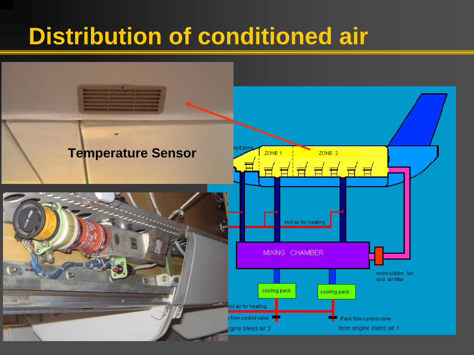
Distribution of conditioned air
Temperature Sensor

Environmental system failures Between 2001 and 2004, 14% of in-flight interruptions havebeen attributed to environmental control system. They can be further divided as shown in the figure.

Water separator is the major problematic component with the highest failures.

AIRCRAFT ENGINESAIRCRAFT ENGINES

Operation of a turbine engine

Turbine engine components

Air inlet

Centrifugal Compressor

Axial flow compressor

Combustion chamber (burner)

Turbine

Exhaust section (Nozzle)

Types of turbine engines

Types of turbine engines

Thrust reversers
Shorten the routine landing distanceReduce the load on the brakesImprove braking control on wet, snow-covered or icy runways

Types of thrust reversers
Clamshell reverser
Cascade reverser

Engine Malfunctions
Compressor Surge:A compressor surge (sometimes called a compressor stall) is the result of instability of the air flow through compressor. It is recognized by a loud bang similar to an explosion. Flame out:A flameout is a condition where the combustion process within the burner has stopped. Hot Start:During engine start, due to fuel scheduling, strong tail wind, etc. turbine temperature rises to relatively high temperatures. This is known as a hot start.

Engine Malfunctions
Foreign Object Damage:Foreign Object Damage (FOD) is ingestion of objects such as tire fragments, runway debris or animals into the engine.Engine Seizure:Engine seizure describes a situation where the engine rotors stop turning in flight, perhaps very suddenly. The static and rotating parts lock up against each other, bringing the rotor to a halt.

Engine failure causes
Major failure causes of aircraft engine during the last four years:- Vibration- Low pressure compressor (N1) problem- Compressor vane

Engine Maintenance
Cold Section- Compressor- Foreign Object DamageHot Section- Combustion chamber, turbine, exhaust- Cracks due to thermal shocks- Dictates TBO (time before overhaul)

Foreign object damage (FOD)

Aircraft corrosion

Most Common Types of Aircraft Corrosion
Pitting corrosionCrevice corrosionIntergranular corrosionExfoliation corrosionBimetalic corrosionStress cracking corrosionFretting corrosion

Pitting corrosion
Pitting corrosion is a localized form of corrosion by which cavities or "holes" are produced in the material.

Crevice corrosion
Crevice corrosion is a localized form of corrosion usually associated with a stagnant solution in crevices (shielded areas) such as those formed under gaskets, washers, insulation material, fastener heads.

Intergranular corrosion
Integranular corrosion is localized attack along the grain boundaries.
Microscopic picture of Inter-granular corrosion of an aircraft component made of 7075-T6 aluminum

Exfoliation corrosion
It is the severe form of intergranularcorrosion.

Bimetalic (dissimilar metal) corrosion
It occurs when two (or more) dissimilar materials are brought into electrical contact under water.
A stainless steel screw in contact with a cadmium plated steel washer.

Stress corrosion cracking
It occurs as the result of the combined effect of sustained tensile stresses and a corrosive environment.
Stress corrosion crack on horizontal stabilizer due to severe metal forming.

Fretting corrosion
It occurs when two mating surfaces, normally at rest which respect to each one another, are subject to slight relative motion.
Corroded pins
Fretting corrosion of tin-plated electrical connector pins mated with gold-plated sockets in F-16 aircraft main fuel shutoff valve.

Corrosion prone areas
Exhaust areasBattery compartment
Engine inlet Wheel well Flap enclosure

Avionic systems corrosion
Avionics are more prone to corrosion than aircraft because;Dissimilar metals are often in electrical contactSmall amount of corrosion can make equipment inoperative

Effect of Atmospheric Conditions
Weather conditions
Atmospheric pollutants

Atmospheric conditions at an air force base in Turkey
ANNUAL MEANPARAMETER
10.32Absolute humidity (g/m3)76.00Relative humidity (%)14.30Temperature (˚C)69.44Rainfall (cm)70.00Particulates (μg/m3)170.00Sulfur dioxide (g/m3)1.50Distance to sea (km)

Protective maintenance against aircraft corrosion
WashingSealing / Application of inhibitorsProtective coating (metallic, organic)Maintaining water drain valves and drain holes for proper operationTraining and equipment

Corrosion
C:\Documents and ettings\Administrato

AIRCRAFT INSPECTION AIRCRAFT INSPECTION METHODSMETHODS

Non-destructive inspection (NDI) methods
Penetrant inspectionMagnetic particle inspectionEddy current inspectionRadiography inspectionUltrasonic inspectionBorescope inspection

Penetrant inspection
1
1 - Cleaning2 - Drying3 - Dye application4 - Inspection
2
3 4
Detects only surface cracksEasiest method

Penetrant inspection
crack

Magnetic particle inspection
1 2
4
1 - Cleaning2 - Magnetization3 - Powder application4 - Inspection
3
Detects surface or near-surface cracks only in ferrous parts.

Magnetic particle inspection
Longitudinal magnetization
Lateral magnetization

Magnetic particle inspection

Magnetic particle inspection
crack

Eddy current testing
Detect surface or near-surface cracks in conductive parts.

Eddy current testing

Eddy current inspection probes
probe

Ultrasonic inspectionIt can detect cracks inside the metallic & nonmetallic part.

Ultrasonic inspection

Ultrasonic inspection techniques(angular application)

Immersed ultrasonic inspection

Radiography Inspection
It can be used to detect crack inside the ferrous and non-ferrous materials

Borescope inspection
It is used to inspect the areas which are hardly accessible such as engine compressor & turbine

Borescope inspection

Borescope kits

Quick reference for choosing appropriate NDI method
NDI methodMaterialDiscontinuity TypePT/ET/RTNonferrous
MT/PT/RTFerrous
RT/ETNonferrous
RT/UTNonferrous/ferrous
UT/RT/ETNonferrousCorrosion
UTMetal/compositesLaminations
RT=Radiographic testing UT=Ultrasonic testing ET=Eddy current testing
MT=Magnetic part testing PT=Penetrant testing
Sub-surface cracks
Surface cracks

AIRCRAFT MAINTENANCEAIRCRAFT MAINTENANCEMANAGEMENT & PLANNINGMANAGEMENT & PLANNING

Maintenance
Maintenance is any one or combination of activities such as;InspectionModificationRepairReplacementOverhaulto restore an aircraft or aircraft component or to keep it in working condition.

Authorities involved in maintenance program development
AUTHORIES
REGULATORYBODIES MANUFACTURERS OPERATORS
•FAA (Federal Aviation administration)•EASA (European Aviation Safety Admin.)•ICAO (International Civil Aviation Organization)

Maintenance Regulations & Documents
Maintenance ManualsService Bulletins Federal Aviation Regulations (FAR)Joint Aviation Requirements (JAR)Airworthiness DirectivesAdvisory CircularsMinimum Equipment List (MEL)Technical orders

Maintenance ProcessesPreventive maintenancePredictive maintenance is performed in order to prevent failure of an item or to discover a hidden failure.Corrective maintenance
Corrective maintenance is performed after the failure to correct the fault.

Maintenance Processes in aviationHard timeOn conditionCondition Monitoring
Maintenance Operations Flight operations

Hard-time Maintenance
It is the oldest, primary preventive maintenance process.
It requires that an appliance or part be periodically overhauled at certain intervals in accordance with the carrier’s maintenance program, or it should be removed from the service.
As soon as the part age reaches predetermined time (flight hour, cycle, or calendar time), it is overhauled or replaced with a new component.

On-condition Maintenance
This is a primary preventive maintenance process.It requires that an appliance or part be periodically inspected or checked against some appropriate physical standards to determine weather it can continue in service.The purpose is to use the part as long as possible before it fails during normal operation (in service operation)

Condition Monitoring
This is a maintenance process for items that have neither “hard time” or “on-condition”maintenance as their primary maintenance process. Condition monitoring is the maintenance process for locating and resolving problem areas through analytical study of malfunctions or failures, not affecting safety of aircraft.

Maintenance Program Development
Maintenance Planning
Document(MPD)
MRBReport
Maintenance Program
Maintenance Review Board (MRB)
OperatorsManufacturer(Maintenance Program
Proposal)

Aircraft operator maintenance program
An air carrier's maintenance program should contain at least the following information:
1) What (Item to be maintained)2) When (time limit) 3) How (task)

1) Items to be maintained (What ?)
The item (part, component, or system) to be maintained should be indicated clearly and accurately. This is done usually by ATA (air Transport Association) Chapter numbers, part serial numbers, etc.

2) Time Limit (When ?)
The time limit is the maintenance interval when you perform the maintenance task. There are three (3) units of measure used to establish these limits. An item may have no limits, one limit, or any combination of these limits.

Time Limit
CALENDER TIMEFLIGHT HOURS CYCLES (no. of landings)

3) Maintenance Tasks (How ?)
These include the maintenance services to be done. The maintenance program consists of three types of tasks:Scheduled maintenance tasksUnscheduled maintenance tasksSpecific maintenance requirements for major components of aircraft (engine, propeller, etc.)

Types of Scheduled Maintenance Tasks (services)
Preflight / post-flightTransit Service Overnight Heavy Service Heavy Maintenance ServiceOverhaul Service

Maintenance tasks and letter checks
In maintenance program, the maintenance tasks which are carried out at the sametime are grouped into maintenance packages.These maintenance packages are indicated by "A", "B", "C" and "D" checks. For this reason they are called "letter checks".

Transfer of task types in maintenance program
CHECKSERVICE TYPE
AOVERNIGHT HEAVY SERVICE
CHEAVY MAINTENANCE SERVICE
DOVERHAUL SERVICE

Military aircraft maintenance
Maintenance levelsOrdinary (O) Intermediate (I) Depot (D)
Maintenance types
Pre-flight inspections, scheduled
maintenance, minor failure repair
Term maintenance, failure repair
Term maintenance, damage repair
Location Squadron Airbase Factory-level facility
Duration Minutes - hours Hours - weeks Weeks - months
Example tasksRefueling, minor
repairs, e.g. light bulb change
Component change/repair, e.g.
hydraulic pump change
Elaborate component or structure
changes/repairs, e.g. bird crash repair

How to package the maintenance tasks?
There are two questions that need to be answered about the TIME LIMIT correctly:
1)What is the best time measurement unit (Calendar day, flight hour or cycle)?
2)What is the optimum time limit for part replacements or inspections?

1) What is the best time measurement unit for me (Calendar day, flight hour or cycle)?
Operator A:Average usage : 7000 fh/year“C” checks: 3500 flight hour
Operator B :Average usage: 7000 fh/year“C” checks: 15 months
Aircraft : Boeing 747-400Usage by design : High daily flight hour utilization“C” check interval: 15 months or 3500 flight hours
Result: Operator A will perform more “C” checks than Operator B which results in increase in maintenance cost with no increased level of safety and reliability.

2) What is the optimum time limit for part scheduled replacements or inspections?
Scheduled tasks are to be performed at regular intervals.Maintenance Planning Document (MPD) prepared by the manufacturer is the main document that provides the user with time intervals for various tasks. However, these are recommended intervals by the manufacturer. Each operator should customize these recommended time intervals based upon its own operating and environmental conditions, maintenance capabilities. To determine the optimal interval is a very difficult task that has to be based on information about the failure rate function.

Operating life and failures of a component
Operating life of a component may include three periods from the failures point of view: Early life periodUseful life periodWear-out life period

Failure Characteristics of aircraft components
Time (flight hours)
Failu
re r
ate
Early life Useful
lifeWearOut
Candidates for periodic replacement
Decreasing failurerate Constant failure
rate Increasing failurerate
10005000

Early life period
Early failures occur early in the operating life of a component and are characterized by a decreasing failure rate with increasing age. Main causes of early failures are:
Poor manufacturing techniquesPoor quality controlImproper storage of the componentImproper installationContamination

Useful life period
Useful life period is characterized by constant (or random) failure rate. During useful life components fail by change unexpectedly. Main causes of change failures are:
MisapplicationAbuseStorms, lightning, etc.Foreign object damage (FOD)

Wear-out period
Wear-out failures occur late in operating life and characterized by an increasing failure rate with increasing age. Main causes of wear-out failures are:
AgingWearFatigueCorrosion and erosionPoor service, maintenance, and repair.

Case studyESTIMATION OPTIMUM TIME OF REPLACEMENT FOR AN AIRCRAFT COMPONENT
Manufacturer's maintenance document recommends replacement of a spring in aircraft APU fuel pump at an interval of 60 flight hours. Although you are applying the manufacturer recommendation, fuel pump often fails unexpectedly and produce many unscheduled maintenance tasks. You are assigned to analyze and recommend solution to this problem.
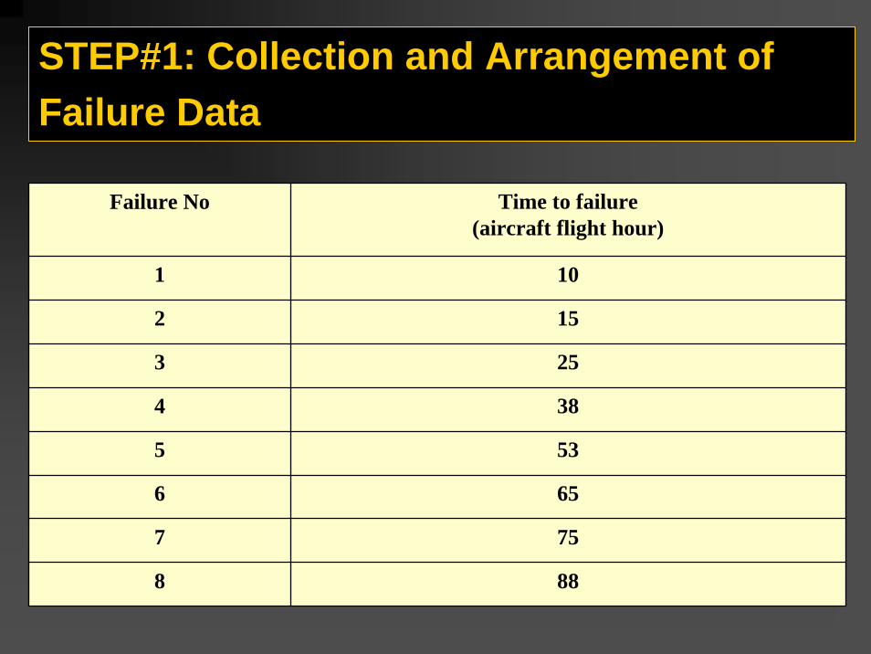
STEP#1: Collection and Arrangement of Failure Data
Time to failure(aircraft flight hour)
Failure No
101
152
253
384
535
656
757
888

STEP#2: Calculation of failure rate
Failure rateTime between failures∆t
Time to
failure(flight hour)
Failure Number( i )
1 / [(5)(8+1-1)]=0.0251010.0141520.013132530.013153840.020125350.033106560.04013757--888
)i1n)(t(1FR
−+Δ=
n= 8 (total number of failures)
15-10=525-15=10
?

STEP#3 : Analysis
0
0.01
0.02
0.03
0.04
0.05
0 20 40 60 80Flight hours
Failu
re ra
te
This is the optimum replacement time
Plot column # 4 vs. Column # 2

CONTINUOUS AIRWORTHINESS MAINTENANCE PROGRAM (CAMP)
A continuous airworthiness maintenance program (CAMP) is the set of processes certificate holders (operators) must use to keep their aircraft in an airworthy condition.The FAA requires operators to establish and maintain two separate, but equal, functions within their CAMP :- required maintenance actions - required maintenance inspection

AIRCRAFT ELECTRICAL SYSTEM

Electrical System
Electrical Power sourcesElectrical Components
- Control devices- Conversion devices- Protection devices.
Power distribution systems and loads

Electric Power Sources
CellTerminals
Container
Main connector
Ventpipe
Ni-Cd Battery Generator
Aircraft equipments operate at two electrical power levels115 VAC @ 400 Hz28 VDC
There are two power sources on the aircraft to generate these electric powers:BatteriesGenerators

Electrical power requirements during a typical flight
0
5
10
15
20
25Ex
terio
r lig
htin
g
Flig
ht c
ompa
rtmen
t lig
htin
g
Pass
enge
r cab
in li
ghtin
g
Gal
ley
Toile
ts
Ente
rtain
men
ts
Win
dshi
eld
heat
ing
Avi
onic
s
Air c
ondi
tioni
ng
Fuel
Hyd
raul
ics
Flig
ht c
ontro
ls
Pow
er R
equi
red
(kW
)

ELECTRICALSYSTEMCOMPONENTS

Electrical components
RELAY
Transformer rectifier unit (TRU)
CIRCUIT BREAKERS

Main electrical system troubles
Open circuit : Circuit that is not complete or continuous. When an open occurs the affected component stop to operate, but the other components still remain in operative condition.
Short Circuit: It occurs when electricity is allowed to take a shortcut through or around a component or system. It has two effects:Affected components have no power and fail to operateThe other component will be subjected to higher level of current causing them to burnout.

Aircraft electrical system diagram

Right generator bus fault

CONTINUOUS AIRWORTHINESS MAINTENANCE PROGRAM (CAMP)
CAMP
SCHEDULEDMAINTENANCE
AIRCRAFT INSPECTION
UNSCHEDULED MAINTENANCE
RELABILITY CONTROL