Aircraft Mooring Device
32
( Word to PDF Converter - Unregistered ) http://www.Word-to-PDF-Converter.net Aircraft mooring device The present invention relates to a device for mooring an aircraft. To avoid the movement of an aircraft in case of strong wind, its front landing gear is moored with the help of at least one line to at least one ring anchored in the ground. Also, the parking places for aircraft comprise at ground level flush rings which do not extend above ground level. To carry out mooring, a first technique consists in providing at least one line whose first end is secured to a ring in the ground and the second end to an anchoring point on the aircraft. To obtain effective anchoring, it is preferable to use two lines which are connected to the aircraft symmetrically so as better to distribute the forces. A second technique consists in providing a single line whose ends are secured to two rings in the ground, disposed symmetrically relative to the front landing gear, the line passing through an anchoring point on the aircraft. This solution has the advantage of distributing symmetrically the forces and requiring only a single line. Moreover, the mooring of the aircraft can also be necessary at the time of loading or unloading the aircraft so as to prevent it from tipping rearwardly. In this case, the mooring is carried out on the front landing gear. These mooring techniques are not satisfactory for the following reasons. Even if the lines can comprise tensioning devices such as a ratchet tensioner, the tension is static and provided for only one condition of the aircraft. However, during its loading or unloading, the suspension of the front landing gear compresses or extends as a function of the load. In the case of extension, if the line or line were already tensioned, the supplemental tension by reason of the elevation of the aircraft can give rise to damage to the mooring. In case of compression, the line or line which were previously tensioned become slack because of the lowering of the aircraft and free in their movements, rendering mooring ineffective. Also, the present invention seeks to overcome the drawbacks of the existing aircraft mooring devices, by providing a new device providing effective mooring continuously, despite changes in the posture of the aircraft. To this end, the invention has for its object a mooring device adapted particularly for an aircraft, comprising at least one line or the like ensuring connection between an anchoring point on the aircraft and the ground, characterized in that it comprises dynamic control means of the tension of the line as a function of variations of the distance between the anchoring point on the aircraft and the ground. This arrangement permits having a line that is always tensioned despite variations of load on the suspension device, during loading or unloading of the aircraft.
-
Upload
pugal-venthan -
Category
Documents
-
view
541 -
download
0
Transcript of Aircraft Mooring Device

( Word to PDF Converter - Unregistered ) http://www.Word-to-PDF-Converter.net
Aircraft mooring device
The present invention relates to a device for mooring an aircraft. To avoid the movement ofan aircraft in case of strong wind, its front landing gear is moored with the help of at least oneline to at least one ring anchored in the ground. Also, the parking places for aircraft compriseat ground level flush rings which do not extend above ground level.
To carry out mooring, a first technique consists in providing at least one line whose first endis secured to a ring in the ground and the second end to an anchoring point on the aircraft. Toobtain effective anchoring, it is preferable to use two lines which are connected to the aircraftsymmetrically so as better to distribute the forces. A second technique consists in providing asingle line whose ends are secured to two rings in the ground, disposed symmetrically relativeto the front landing gear, the line passing through an anchoring point on the aircraft. Thissolution has the advantage of distributing symmetrically the forces and requiring only a singleline.
Moreover, the mooring of the aircraft can also be necessary at the time of loading orunloading the aircraft so as to prevent it from tipping rearwardly. In this case, the mooring iscarried out on the front landing gear.
These mooring techniques are not satisfactory for the following reasons. Even if the lines cancomprise tensioning devices such as a ratchet tensioner, the tension is static and provided foronly one condition of the aircraft. However, during its loading or unloading, the suspension ofthe front landing gear compresses or extends as a function of the load. In the case ofextension, if the line or line were already tensioned, the supplemental tension by reason of theelevation of the aircraft can give rise to damage to the mooring. In case of compression, theline or line which were previously tensioned become slack because of the lowering of theaircraft and free in their movements, rendering mooring ineffective.
Also, the present invention seeks to overcome the drawbacks of the existing aircraft mooringdevices, by providing a new device providing effective mooring continuously, despitechanges in the posture of the aircraft.
To this end, the invention has for its object a mooring device adapted particularly for anaircraft, comprising at least one line or the like ensuring connection between an anchoringpoint on the aircraft and the ground, characterized in that it comprises dynamic control meansof the tension of the line as a function of variations of the distance between the anchoringpoint on the aircraft and the ground. This arrangement permits having a line that is alwaystensioned despite variations of load on the suspension device, during loading or unloading ofthe aircraft.

( Word to PDF Converter - Unregistered ) http://www.Word-to-PDF-Converter.net
Preferably, the device is adapted to occupy two conditions, the first so-called free condition inwhich it is adapted to follow the variations of distance between the anchoring point on theaircraft and the ground, by permitting elongation or shortening of the line, and a secondso-called blocked condition, in which it opposes the unwinding of the line. According toanother characteristic, the device comprises means adapted to measure the speed ofunwinding of the line, said device passing from the free condition to the blocked conditionwhen the unwinding speed exceeds a certain threshold or is subject to abrupt acceleration.
This arrangement permits limiting the risk of swinging of the aircraft rearwardly or itsmovement during a strong gust of wind.
Other characteristics and advantages will become apparent from the description whichfollows, of the invention, which description is given only by way of example, with respect tothe accompanying drawings, in which:
FIG. 1 is a side elevational view of an aircraft.
FIG. 2 is a view showing the mooring device of the front landing gear of the aircraft.
FIG. 3 is a detailed view showing one embodiment of a device for dynamic control of thetension of the line according to the invention, and
FIG. 4 is a schematic view illustrating the fluid circuits of the device of FIG. 3.
In FIG. 1, there is shown at 10 an aircraft comprising particularly a front landing gear 12shown in detail in FIG. 2.
So as to immobilize the aircraft 10 and/or to avoid its rearward swinging during loading orunloading, the upper portion of the front landing gear 12 disposed above the suspension (notshown) and secured to the body of the aircraft, is connected to the ground with the help of amooring device 14.
One or more so-called anchoring rings 16 are provided at ground level so as to permit easieranchoring. These rings are preferably flush in horizontal position and disposed on each sideof the front landing gear 12 so as to obtain symmetric distribution of the forces due tomooring.
According to techniques used, the mooring device 14 comprises one or more lines 18connecting the upper part of the front landing gear to the ground. According to a preferredembodiment shown in FIG. 2, the securing device comprises a line 18 whose ends areconnected to anchoring rings 16, said line passing through a ring or opening 20, calledanchoring point of the aircraft, provided in the upper portion of the front landing gear. As a

( Word to PDF Converter - Unregistered ) http://www.Word-to-PDF-Converter.net
modification, there could be provided two lines 18, each having a first end connected to theanchoring point of the aircraft and a second end connected to the ground.
To permit easy securement, the line or lines comprise at their ends hooks 22, preferably witha tongue or in the form of a snap hook.
The line or lines 18 have a suitable length, and are made of suitable material to permitwithstanding the forces. Moreover, a line can be made in a single piece or from severalelements disposed end to end. Finally, the line can have different cross-sectional shapes, saidsections being constituted by a single element or several elements disposed parallel ortwisted.
In known manner, the line can be provided or not with static tensioning means 24 such as aratchet tensioner.
According to the invention, the mooring device 14 comprises means 26 to control the tensionof a line 18 dynamically, adapted to adjust the unwinding of the line 18 as a function of thevariation or variations of the distance separating the anchoring point 20 on the aircraft withthe anchoring point 16 on the ground.
According to a preferred embodiment shown in FIG. 2, the mooring device 14 comprises acarriage 28, with preferably at its lower portion rollers 30 and at its upper portion a handle 32facilitating its movement, and a line 18 connected to a first end of the carriage 18 andcomprising at the other end a hook 22, a ratchet tensioner 24 being preferably provided on theline. Preferably, the carriage 28 comprises means 34 for storing the line which can or notpermit the automatic rewinding of said line 18.
In its lower portion, the carriage 28 comprises means for securement to the ground in theform for example of a hook 36 permitting the securement of the carriage and hence its line 18to an anchoring ring.
As a modification, the carriage 28 can be connected to several lines 18.
According to the invention, the dynamic control device 26 for the tension of a line 18 isdisposed on the carriage 28. This device 26 permits adjusting automatically and continuouslythe length of the line 18, when the distance separating the anchoring point 20 on the aircraftand the anchoring point on the ground varies, particularly during loading or unloading of theaircraft.
Preferably, this device 26 comprises means adapted to measure the speed of unwinding of theline 18. Thus, as soon as the speed of unwinding exceeds a certain threshold or is subject toabrupt acceleration, particularly when the aircraft tends to swing rearwardly or during a gust

( Word to PDF Converter - Unregistered ) http://www.Word-to-PDF-Converter.net
of wind, the device opposes the unwinding of the line so as to maintain a constant lengthbetween the anchoring point 20 on the aircraft and the anchoring point 16 on the ground.
The dynamic control device 26 for the tension of a line comprises means 38 which tend totension the line 18, said means 38 being adapted to occupy two conditions, a first so-calledfree condition in which it is adapted to follow the variations of distance between theanchoring point 20 of the aircraft and the anchoring point 16 on the ground, by exerting onthe line 18 a substantially constant tension and by permitting the elongation or shortening ofthe line, and a second so-called blocked condition, in which it opposes the unwinding of theline.
According to a preferred embodiment and shown in FIGS. 3 and 4, the means 38 are presentin the form of a single acting jack 40, or preferably two jacks, whose base 42 of the body isconnected to the upper portion of the carriage 28 and whose piston 44 oriented downwardlycomprises at its end a shell 46 supporting a pulley or roller 48 adapted to apply tension to theline 18, whose first length at its end connected to the upper portion of the carriage 88 andsecond length 52 leave by an opening 54 also provided in the upper portion of the carriage 28.The jack or jacks 40 are single acting and tend to tension the line 18, as shown by the arrow56. Thus, for a path of X mm of the piston 44, there is obtained a variation in the length of theline of 2X mm. In FIG. 3, there is shown the assembly in two different positions, pistonscompressed and pistons extended.
As shown in FIG. 4, the jack or jacks 40 are connected to a reservoir 58 of fluid so as toensure permanent adjustable tension in the line 18, particularly when the distance between theanchoring point 20 of the aircraft and the anchoring point to the ground decreases.
A unidirectional flow rate regulator 60, provided between the jack or jacks 40 and thereservoir 58, ensures a shock absorbing function to the unwinding of the line 18 and permitsthe compression of the jack or jacks 40, particularly when the distance between the anchoringpoint 20 of the aircraft and the anchoring point 16 on the ground increases. This regulator 60also permits controlling the speed of unwinding of the line 18. Thus, as soon as the speedexceeds a certain threshold or is subject to abrupt acceleration, the regulator opposes the flowof fluid between the jack or jacks 40 and the reservoir 58, such that the jack or jacks 40 are inthe blocked condition and oppose the unwinding of the line 18.
A so-called bypass valve 62 can be provided in parallel to the regulator 60 to connect the jackor jacks to the reservoir 58.
The operation of the device of the invention will now be described.
The carriage 28 is moved near the front landing gear 12 and its hook 36 is hooked to ananchoring ring 16. Then, the operator passes the line 18 through the anchoring point 20 of the

( Word to PDF Converter - Unregistered ) http://www.Word-to-PDF-Converter.net
aircraft and hooks the hook 22 to a second anchoring ring 16. He exerts a tension on the line18 with the help of the ratchet tensioner 24 so as to place the tensioning means 38 in anappropriate condition. If the aircraft is loaded and the shock absorber of the front landing gearmust extend, the tensioning means 38 will be almost not compressed. On the contrary, if theaircraft must be loaded and the front landing gear shock absorber must compress, the tensionmeans will be compressed so as to be able to exert tension on the line.
During hooking and adjustment of the tension, the exhaust of the jack or jacks is open, thevalve 52 being open. Afterward, in operation, the exhaust of the jack or jacks is controlled,and the valve 62 is closed.
According to another characteristic of the invention, visual information can be provided topermit adjustment of the tension at the time of correct mooring.

( Word to PDF Converter - Unregistered ) http://www.Word-to-PDF-Converter.net
Unit - 4: Auxiliary system (also called utility system)
Terminal Objectives: Upon completion of this chapter, you will have a working knowledge ofbleed-air, liquid cooling, windshield wiper/ washer, rain repellant, fire extinguishing, andthermal radiation protection utility systems.
The utility systems of an aircraft provide an additional measure of flight safety, pilot comfortand convenience, and contributes to the overall mission capability of the aircraft. Those utilitysystems of primary concern to you that are included in this chapter are the various bleed-air,liquid cooling, fire extinguishing, and thermal radiation protection systems.
AUXILIARY BLEED-AIR SYSTEMS Learning Objective: Recognize the operatingprinciples and functions of auxiliary bleed-air utility systems. An aircraft's auxiliary bleed-airsystem furnishes supply air for air-conditioning and pressurization systems, as well as forelectronic equipment cooling, windshield washing, anti-icing, and anti-g systems. Thebleed-air system also pressurizes fuel tanks, hydraulic reservoirs, and radar waveguides onseveral types of aircraft.
The air for these systems is tapped off downstream of the air-conditioning turbine before anycooling takes place, or at various points within the air-conditioning system. Bleed air forthese systems can range Up to 400° F (205° C) at pressures of up to 125 psi. Because eachtype of aircraft has a somewhat different approach in system design, temperatures, andpressures, the systems and components in this manual will be representative of types foundthroughout the Navy. Under no circumstances should this manual be regarded as the finalsource of technical data used to perform aircraft maintenance. For the
most up-to-date information, refer to the proper Maintenance Instructions Manual (MIM) forthe system concerned.
WINDSHIELD ANTI-ICE/ RAIN REMOVAL SYSTEM This system is designed toprovide a means of maintaining visibility from the aircraft. The F-18 windshield anti-ice/ rainremoval system is typical of systems found in jet air-craft. This system supplies controlledtemperature air from the air cycle air-conditioning system (ACS) to provide airflow over theexternal surface of the windshield for rain removal and windshield anti-icing.
System Control The system is electrically controlled and pneumatically operated. There arethree modes of operation controlled by the windshield anti-ice/ rain removal switch.

( Word to PDF Converter - Unregistered ) http://www.Word-to-PDF-Converter.net
1. OFF. The anti-ice/ rain removal air control regulating valve is closed, and there is noairflow over the windshield. 2. RAIN. Low-pressure (2.5 psig) and low-volume (20 lbs/ min)air at 250° F directed across the windshield through the anti-ice/ rain removal nozzle.
3. ANTI-ICE. High-pressure (16 psig) and high-volume (57 lbs/ min) air at 250° F directedacross the windshield through the anti-ice/ rain removal nozzle.
Low Limit Temperature Control Refer to figure 1-1 for component location. The supply airtemperature is controlled to a lower limit of 290° F by the warm air temperature control valveand the warm air temperature sensor. If air temperature supplied by the air cycle ACS exceeds290° F, the warm air temperature control valve will close and stop airflow from the bleed-airsystem. The 290° F supply temperature is cooled as it passes through the ducting toapproximately 250° F at the nozzle. The 250° F temperature provides enough heat forwindshield deicing, yet is low enough to prevent damage to the windshield.
High Limit Temperature Control The warm air over temperature sensor actuates whensupply air temperature reaches 375°± 25° F and signals the flow/ temperature limiting anti-icemodulating valve. This valve regulates airflow supply, which reduces bleed airflow throughthe primary heat exchanger and reduces airflow
Figure 1-1.- Windshield Anti-ice and rain removal system component locator.
supply temperature to below 375°± 25° F. The combined action of the warm air overtemperature sensor and flow/ temperature limiting anti-ice modulating valve also provides therequired protection against a defective warm air temperature control valve.
Anti-Ice/ Rain Removal Air Control Regulating -Valve The anti-ice/ rain removal aircontrol regulating valve completes the final pressure regulation and flow control before

( Word to PDF Converter - Unregistered ) http://www.Word-to-PDF-Converter.net
airflow reaches the anti-ice/ rain removal nozzle. The valve regulates pressure and flow ratedepending on the position of the windshield anti-ice/ rain removal s w i t c h.
Windshield Overheat Temperature Sensor The windshield overheat temperature sensor,located downstream of the anti-ice/ rain removal air control regulating valve, is atemperature-activated switch, which opens if airflow temperature reaches 290°± 5° F. Itcloses when airflow temperature drops to 280°± 5° F. When the switch is open, a ground islost to the signal data converter and the signal data computer, which causes the digital displayindicator to display a (WDSHLD HOT) caution message.
ANTI-G SYSTEM The anti-g system supplies and controls the flow of air pressure to thepilot's anti-g suit to compensate for forces exerted upon the human body during flightconditions. This system is designed to accomplish the following:
1. Provide protection against grayout, blackout, and unconsciousness
2. Alleviate fatigue and decreased mental alertness, which may result from repeatedaccelerations below the blackout level
3. Provide a method by which the pilot may relieve leg stiffness and physical tension duringflight
4. Provide the pilot with a physical indication of the approximate acceleration to which theair-craft is being subjected

( Word to PDF Converter - Unregistered ) http://www.Word-to-PDF-Converter.net
Engineering Aerospace: Aircraft FuelSystems
Minimal functional requirement of fuel systems is to supply fuel to the engine in sufficientquantity and quality and at a certain pressure. The system contains of two sub-systems; thefuselage fuel system and the engine fuel system. This web page deals with the formersub-system.
The construction of the fuel tank system largely depends on the task of getting the fuel fromthe tank to the tank's exit, and from the tank's exit to the engine. The location of the tanks isusually determined by the platform's structure, available space and impact on CG (centre ofgravity) location. In some aircraft, external tanks, belly tanks or tip tanks may be fitted. Whenadditional fuel is needed, for example, for an extended range, ferry tanks are employed.
Belly Tank[http://www.airglas.com/belly_tank/index
.html]
External Tank[http://aeroweb.brooklyn.cuny.edu/specs/mcdodoug/fa
-18b.htm]
Tip Tank Ferry Tank
Components of fuel systemLow pressure feed system
Plumbing
Plumbing is the name given to the fuel supply lines. They are depicted as solid in theillustration but in real life obviously this is not true.
Lines are generally made from metallic tubing, not pipes.
Routing must be placed on the opposite side of the aircraft from the oxygen supplyand below any electrical wiring.
The flow of fuel inside the fuel lines may produce static electricity. The lines are

( Word to PDF Converter - Unregistered ) http://www.Word-to-PDF-Converter.net
therefore electrically connected to prevent any electrical charge accumulation.
Fuel tank
This is the fuel storage component. It must be large enough to carry fuel for the wholemission.
Fuel tanks must have means of dumping fuel in cases of emergency.
They must be vented so that used fuel may be replaced by air or inert gases. If there isinsufficient flow of air into the tank, it may collapse (due to loading caused by highperformance or steep descend from altitude to sea level). For integral wing tanks, thepressure difference may cause structural damage and component failure.
Fuel tanks may have a sump which collects water and solid particles in fuel.
Level indicator
As the name suggests, this component provides the flight crew with the currentmeasurement of fuel content.
Fuel measurement are difficult to measure as they depend on fuel tank shape andaircraft attitude.
Pumps
The pumps may be mounted externally or immersed in the fuel.
It is important that the pumps are free of fuel vapour intrusion as they supply fuel tothe engine. To avoid this, air separators are installed at the pump inlets.
Pressure switch
The switch gives no indicator of the pressure value but rather reacts to the presence ofpressure which is above the pre-set lower limit of the switch.
Relying solely on pump power indication is insufficient because even though powerswitch may be on, the pump may not be working due to seized rotor or blocked inlet.The pressure switch accounts for this.
It gives the flight crew an indication of which pumps are operating since not all pumpsare switched on during operation (during take-off and aerobatics, both pumps are on).
Non Return Valves (NRV's)
Since during operation only one pump may be working, the NRV ensures that fuelpumped from the operating pump is not returned to the fuel tank via inoperativepump.
Pump by-pass valve
This valve allows the fuel from other tanks to enter the indicated tank.
If incorporated with a cross feed valve, it becomes a three way valve.

( Word to PDF Converter - Unregistered ) http://www.Word-to-PDF-Converter.net
Tank isolation valve
This valve isolates the tank from the fuel system. This is usually done in cases ofemergency or if a fuel leak develops in the tank, thus draining the remaining aircraftfuel.
Under normal operating conditions, this valve is open.
Cross feed valve
Requirements state that the engine may only be supplied with fuel from one tank at atime. The cross feed valve allows for this. It supplies fuel from other tanks.
This valve is usually closed under normal operating conditions.
Low pressure valve
This valve is fitted after all tanks have had access to the fuel line.
It allows maintenance on any part of the fuel circuit in the fuselage that is notconnected to the tank fuel distribution circuit.
Power drain valve
This valve allows quick discharge of fuel from the system for maintenance oremergency purposes.
Power drain valve must be closed before engine start up.
High pressure feed system
Backing pump
This is not an essential component, however, in case the engine requires a fuelpressure higher than that produced by tank pumps, this pump is able to do so.
It is required that the engine must still operate without the use of this pump.
Fuel Cool Oil Cool (FCOC)
The volatility (ability of evaporate) of fuel may be increased by heating it. This isparticularly important if fuel is supplied from wing tanks where it has been exposed tolow temperature soak at altitude.
The hot oil from engine heats up the cool fuel and in the process cools itself off, thusreducing the number of oil cooling components in the platform.
Fuel heater
If additional fuel heating is required, the fuel heater is able to do this by the use of

( Word to PDF Converter - Unregistered ) http://www.Word-to-PDF-Converter.net
high pressure compressor gas.
Fuel filter
As the name suggests, this component filters out unwanted particles contained in thefuel.
The filter may be configured to trap water, in which case, it may become blocked updue to ice formation.
To avoid clogging when contaminants and/or ice are trapped, a bypass valve isinstalled to get around a blocked filter.
Regular inspection is essential unless the filter is equipped with an electricalsignalling device which indicates blockage.
Generally, change over from fuselage to engine occurs between these two components.
Flow meter
Quantity of fuel supplied to the engine is an important piece of information formanagement of flight fuel use.
If installed as it is depicted in the above illustration, it doesn't account for the fuelbypassing the engine and returning to tanks.
To give a correct fuel flow to engine indication, it can be installed after the fuelcontrol unit (FCU) where any fuel flowing must go to the engine.
Pressure transmitter
This transmitter measures the pressure of the fuel entering the engine.
If there is a problem during the mission, the flight crew can eliminate the fuel pressureas a cause of this problem by reading the value off the pressure transmitter.
Pressure switch
This switch monitors the pressure of fuel entering the engine. If a low pressure issensed, the switch automatically alerts the crew and activates master caution warning.
High Pressure pump (HP pump)
This gear pump supplies the engine with fuel and is driven through an accessorygearbox mounted to the engine.
It is capable of producing pressures of up to 5.5 MPa.
Aircraft Engine instrumentsHere is a brief description of the recommended instruments for 2 and 4 stroke AircraftEngine monitoring and the reasons why they are necessary. These informations and muchmore can be found in our Engine Maintenance Logs.

( Word to PDF Converter - Unregistered ) http://www.Word-to-PDF-Converter.net
At Aero PropulsionTechnologies, we designed acheat sheet in business cardformat which shows you theallowable temperatures foryour 2-stroke engine. Ask usfor one or print one yourself bydownloading the followingfile:
2-stroke Aircraft EnginesCylinder Head Temperature (CHT) and Liquid TemperatureThe cylinder head temperature instrument is very useful on an air-cooled engine. It isless so on a liquid-cooled engine, where it is replaced by a liquid temperatureinstrument.On an air cooled engine, it is recommended to have a probe for each cylinder, as bothcylinder heads are separate. A liquid cooled engine, with its joined cylinder head, onlyrequires one probe.In both cases, it is important to regularly monitor the temperatures in flight asabnormal overheating can indicate a cooling problem, faulty lubrication or too lean afuel/air mixture.
Exhaust Gas Temperature (EGT)This instrument is very useful on any type of engine as it offers an insight oncombustion temperatures. It is wise to monitor it in flight but it is particularly usefulon the ground for carburetor tuning. Too high a temperature indicates too lean afuel/air mixture, while too cold a temperature indicates a rich mixture. Adjustingmixture to the ideal temperatures allows the engine to run at optimal efficiency.It is recommended to use one probe for each cylinder to ensure they run in unison.Please note that the readings of certain CHT and EGT probes are affected by ambienttemperature. Check your instrument and probe instructions for details.
Tachometer

( Word to PDF Converter - Unregistered ) http://www.Word-to-PDF-Converter.net
The tachometer measures the number of revolutions the engine performs per minute.It is useful in evaluating engine performance. For example, too low or too high amaximum engine speed at takeoff can reveal a problem. It is also useful in setting thepropeller pitch to allow the engine to reach its optimal takeoff and cruise speeds.
HourmeterThis instrument counts the number of hours your engine has been running. It isparticularly useful in keeping a maintenance log!
Aero Propulsion Technologies offers a full range of engine instruments
At Aero PropulsionTechnologies, we designed acheat sheet in bookmarkformat which shows you theallowable temperatures foryour 4-stroke engine. Ask usfor one or print one yourself bydownloading the followingfile:4STref.pdf / 153Kb /Adobe Acrobat forma
4-stroke Aircraft EnginesOil PressureThe oil pressure instrument monitors the proper operation of your engine’s lubricationsystem. It may reveal a low oil level, leaks, restrictions and other system malfunctions.
Oil TemperatureThe oil temperature instrument allows you to ensure that your engine’s lubricant isoperating at the proper temperature. Oil lubricates optimally only within a specificrange of temperatures which should be reached at warmup and preserved at all times.It may reveal insufficient or excessive oil radiator cooling and may reveal somelubrication system malfunctions.

( Word to PDF Converter - Unregistered ) http://www.Word-to-PDF-Converter.net
Cylinder Head Temperature (CHT)We found that many pilots confuse this instrument with a coolant temperatureinstrument, and sometimes label it as such. The probe to this instrument actuallymeasures the temperature of the metal in your cylinder head. It allows you to monitorthe proper operation of the liquid cooling system that cools your cylinder heads yet itdoes not measure the actual temperature of that liquid.
Exhaust Gas Temperature (EGT)This instrument measures the temperature of your exhaust gases as they exit thecombustion chamber and pass through the exhaust manifold. It offers an insight oncombustion temperatures and allows you to monitor the quality of the air/fuel mixture.Too high a temperature would indicate a lean mixture, while too low would indicate arich mixture. It may also reveal loss of compression in the cylinders.
Fuel PressureThe fuel pressure instrument indicates the proper operation of your fuel pump and fuelsupply system. It may reveal leaks, restrictions or a malfunction of the carburetor floatvalve system.
Manifold PressureThis instrument offers an insight on how hard the engine is working. The moreair/fuel mixture entering the engine, the higher the manifold pressure will be. It isparticularly useful in setting the propeller pitch for optimal engine efficiency atdifferent power settings. It may also reveal leaks in the intake system.
Coolant temperatureNo provision for a coolant temperature probe is provided on Rotax 4-stroke enginesand for good reason: the Cylinder Head Temperature instrument offers a better insightinto the proper operation of the liquid cooling system and may reveal problems, suchas the formation of air bubbles, that a coolant temperature instrument would not.
Coolant pressureA coolant pressure probe may be installed, as it can help monitor the general operationof the cooling system and may reveal leaks and restrictions.
TachometerThe tachometer measures the number of revolutions the engine performs per minute.It is useful in evaluating engine performance. For example, too low or too high amaximum engine speed at takeoff can reveal a problem. It is also useful in setting thepropeller pitch to allow the engine to reach its optimal takeoff and cruise speeds.
HourmeterThis instrument counts the number of hours your engine has been running. It isparticularly useful in keeping a maintenance log!
Aero Propulsion Technologies offers a full range of engine instrumentsV.S.Venkataraman

( Word to PDF Converter - Unregistered ) http://www.Word-to-PDF-Converter.net
Providing Superior Products and Unparalleled CustomerService Since 1979 Home Panel Pics Contact Us Downloads Testimonials Dealer List Returns
Glass PanelMVP-50P PistonMVP-50P TurbopropEngine Analyzers

( Word to PDF Converter - Unregistered ) http://www.Word-to-PDF-Converter.net
UBG-16 Bar GraphUS-8A (16 Channels)SR-8A (8 Channels)Fuel Flow/PressurePrimaryStandardRPMR-1 TachometerManifold PressureM-1 Manifold PressureVolts & AmpsVA-1A VoltammeterOil Pressure/TempOPT-1 Press/TempFuel LevelFL-2 Dual LevelFL-1 Single LevelTemp InstrumentsSingle ChannelMulti-ChannelRemote SwitchesPrimary Remote SwitchesClocksASC-5A Altitude ClockSC-5 Super ClockTurbopropR-1 N1 (NG)R-1 N2 (NP)M-1-ITTM-1-T (Torque)M-1-TOTAccessoriesAnnunciatorsProbesPressure TransducersFlow TransducersProduct Overview
Every EI product is proudly designed, manufactured andsupported in Bend, Oregon, USA
THE MVP-50P is NOW STC'D for Single and TWINAircraft! UBG-16 REBATES!!

( Word to PDF Converter - Unregistered ) http://www.Word-to-PDF-Converter.net
STC'd, TSO'd Piston
TSO'd Turboprop
STC'd EGT/CHT Bar Graph
STC'd, TSO'd Fuel Flow &Pressure
STC'd, TSO'd DigitalTachometer
STC'd, TSO'd ManifoldPressure
STC'd, TSO'd OilPressure/Temp
Fuel Level
STC'd Volts & Amps
STC'd, TSO'd Single ChannelTemp
STC'd, TSO'd Multi ChannelTemp
Digital Clocks

( Word to PDF Converter - Unregistered ) http://www.Word-to-PDF-Converter.net
STC'd, TSO'd Probes
STC'd, TSO'd Annunciators
A gyroscope is a device for measuring or maintaining orientation, based on the principles ofconservation of angular momentum.A mechanical gyroscope is essentially a spinning wheelor disk whose axle is free to take any orientation. This orientation changes much less inresponse to a given external torque than it would without the large angular momentumassociated with the gyroscope's high rate of spin. Since external torque is minimized bymounting the device in gimbals, its orientation remains nearly fixed, regardless of any motionof the platform on which it is mounted.
Gyroscopes based on other operating principles also exist, such as the electronic,microchip-packaged MEMS gyroscope devices found in consumer electronic devices, solidstate ring lasers, fibre optic gyroscopes and the extremely sensitive quantum gyroscope.
Applications of gyroscopes include navigation (INS) when magnetic compasses do not work(as in the Hubble telescope) or are not precise enough (as in ICBMs) or for the stabilization offlying vehicles like radio-controlled helicopters or UAVs. Due to their high precision,gyroscopes are also used to maintain direction in tunnel mining.[2]

( Word to PDF Converter - Unregistered ) http://www.Word-to-PDF-Converter.net
Contents
1 Description and diagram
2 History
3 Properties
4 Variations
4.1 Gyrostat
4.2 MEMS
4.3 FOG
4.4 VSG or CVG
4.5 DTG
4.6 London moment
5 Modern uses
6 See also
7 References
8 Further reading
9 External links
Description and diagram
Diagram of a gyro wheel. Reaction arrows about the output axis (blue) correspond to forcesapplied about the input axis (green), and vice versa.Within mechanical systems or devices, a conventional gyroscope is a mechanism comprisinga rotor journalled to spin about one axis, the journals of the rotor being mounted in an innergimbal or ring, the inner gimbal is journalled for oscillation in an outer gimbal which isjournalled in another gimbal for a total of three gimbals.

( Word to PDF Converter - Unregistered ) http://www.Word-to-PDF-Converter.net
The outer gimbal or ring which is the gyroscope frame is mounted so as to pivot about anaxis in its own plane determined by the support. This outer gimbal possesses one degree ofrotational freedom and its axis possesses none. The next inner gimbal is mounted in thegyroscope frame (outer gimbal) so as to pivot about an axis in its own plane that is alwaysperpendicular to the pivotal axis of the gyroscope frame (outer gimbal). This inner gimbal hastwo degrees of rotational freedom. Similarly, next innermost gimbal is attached to the innergimbal which has three degrees of rotational freedom and its axis possesses two.
The axle of the spinning wheel defines the spin axis. The rotor is journaled to spin about anaxis which is always perpendicular to the axis of the innermost gimbal. So, the rotorpossesses four degrees of rotational freedom and its axis possesses three. The wheel respondsto a force applied about the input axis by a reaction force about the output axis.
The behaviour of a gyroscope can be most easily appreciated by consideration of the frontwheel of a bicycle. If the wheel is leaned away from the vertical so that the top of the wheelmoves to the left, the forward rim of the wheel also turns to the left. In other words, rotationon one axis of the turning wheel produces rotation of the third axis.
A gyroscope flywheel will roll or resist about the output axis depending upon whether theoutput gimbals are of a free- or fixed- configuration. Examples of some free-output-gimbaldevices would be the attitude reference gyroscopes used to sense or measure the pitch, rolland yaw attitude angles in a spacecraft or aircraft.
Animation of a gyro wheel in actionThe centre of gravity of the rotor can be in a fixed position. The rotor simultaneously spinsabout one axis and is capable of oscillating about the two other axes, and thus, except for itsinherent resistance due to rotor spin, it is free to turn in any direction about the fixed point.Some gyroscopes have mechanical equivalents substituted for one or more of the elements,e.g., the spinning rotor may be suspended in a fluid, instead of being pivotally mounted ingimbals. A control moment gyroscope (CMG) is an example of a fixed-output-gimbal devicethat is used on spacecraft to hold or maintain a desired attitude angle or pointing directionusing the gyroscopic resistance force.
In some special cases, the outer gimbal (or its equivalent) may be omitted so that the rotor hasonly two degrees of freedom. In other cases, the centre of gravity of the rotor may be offsetfrom the axis of oscillation and thus the centre of gravity of the rotor and the centre ofsuspension of the rotor may not coincide.
[edit] History
( Word to PDF Converter - Unregistered ) http://www.Word-to-PDF-Converter.net
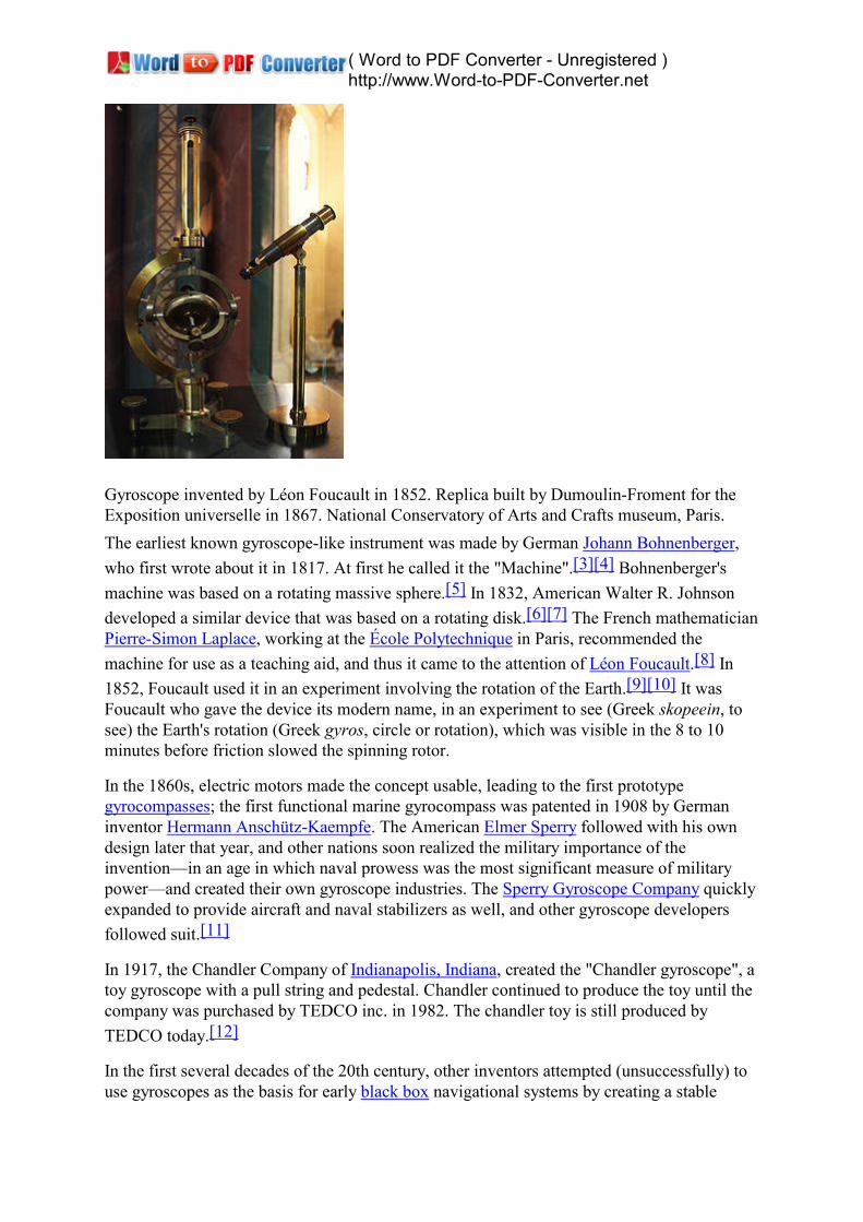
Gyroscope invented by Léon Foucault in 1852. Replica built by Dumoulin-Froment for theExposition universelle in 1867. National Conservatory of Arts and Crafts museum, Paris.The earliest known gyroscope-like instrument was made by German Johann Bohnenberger,who first wrote about it in 1817. At first he called it the "Machine".[3][4] Bohnenberger'smachine was based on a rotating massive sphere.[5] In 1832, American Walter R. Johnsondeveloped a similar device that was based on a rotating disk.[6][7] The French mathematicianPierre-Simon Laplace, working at the École Polytechnique in Paris, recommended themachine for use as a teaching aid, and thus it came to the attention of Léon Foucault.[8] In1852, Foucault used it in an experiment involving the rotation of the Earth.[9][10] It wasFoucault who gave the device its modern name, in an experiment to see (Greek skopeein, tosee) the Earth's rotation (Greek gyros, circle or rotation), which was visible in the 8 to 10minutes before friction slowed the spinning rotor.
In the 1860s, electric motors made the concept usable, leading to the first prototypegyrocompasses; the first functional marine gyrocompass was patented in 1908 by Germaninventor Hermann Anschütz-Kaempfe. The American Elmer Sperry followed with his owndesign later that year, and other nations soon realized the military importance of theinvention—in an age in which naval prowess was the most significant measure of militarypower—and created their own gyroscope industries. The Sperry Gyroscope Company quicklyexpanded to provide aircraft and naval stabilizers as well, and other gyroscope developersfollowed suit.[11]
In 1917, the Chandler Company of Indianapolis, Indiana, created the "Chandler gyroscope", atoy gyroscope with a pull string and pedestal. Chandler continued to produce the toy until thecompany was purchased by TEDCO inc. in 1982. The chandler toy is still produced byTEDCO today.[12]
In the first several decades of the 20th century, other inventors attempted (unsuccessfully) touse gyroscopes as the basis for early black box navigational systems by creating a stable

( Word to PDF Converter - Unregistered ) http://www.Word-to-PDF-Converter.net
platform from which accurate acceleration measurements could be performed (in order tobypass the need for star sightings to calculate position). Similar principles were lateremployed in the development of inertial guidance systems for ballistic missiles.[13]
During World War Two, the gyroscope became the prime component for aircraft andanti-aircraft gun sights.[14]
[edit] Properties
A gyroscope in operation with freedom in all three axes. The rotor will maintain its spin axisdirection regardless of the orientation of the outer frame.A gyroscope exhibits a number of behaviours including precession and nutation. Gyroscopescan be used to construct gyrocompasses which complement or replace magnetic compasses(in ships, aircraft and spacecraft, vehicles in general), to assist in stability (Hubble SpaceTelescope, bicycles, motorcycles, and ships) or be used as part of an inertial guidance system.Gyroscopic effects are used in tops, boomerangs, yo-yos, and Powerballs. Many other rotatingdevices, such as flywheels, behave gyroscopically although the gyroscopic effect is not beingused.
The fundamental equation describing the behavior of the gyroscope is:
where the vectors τ and L are, respectively, the torque on the gyroscope and its angularmomentum, the scalar I is its moment of inertia, the vector ω is its angular velocity, and thevector α is its angular acceleration.
It follows from this that a torque τ applied perpendicular to the axis of rotation, and thereforeperpendicular to L, results in a rotation about an axis perpendicular to both τ and L. Thismotion is called precession. The angular velocity of precession ΩP is given by the crossproduct:

( Word to PDF Converter - Unregistered ) http://www.Word-to-PDF-Converter.net
Precession on a gyroscopePrecession can be demonstrated by placing a spinning gyroscope with its axis horizontal andsupported loosely (frictionless toward precession) at one end. Instead of falling, as might beexpected, the gyroscope appears to defy gravity by remaining with its axis horizontal, whenthe other end of the axis is left unsupported and the free end of the axis slowly describes acircle in a horizontal plane, the resulting precession turning. This effect is explained by theabove equations. The torque on the gyroscope is supplied by a couple of forces: gravity actingdownwards on the device's centre of mass, and an equal force acting upwards to support oneend of the device. The rotation resulting from this torque is not downwards, as might beintuitively expected, causing the device to fall, but perpendicular to both the gravitationaltorque (horizontal and perpendicular to the axis of rotation) and the axis of rotation(horizontal and outwards from the point of support), i.e. about a vertical axis, causing thedevice to rotate slowly about the supporting point.
Under a constant torque of magnitude τ, the gyroscope's speed of precession ΩP is inverselyproportional to L, the magnitude of its angular momentum:
where θ is the angle between the vectors ΩP and L. Thus if the gyroscope's spin slows down(for example, due to friction), its angular momentum decreases and so the rate of precessionincreases. This continues until the device is unable to rotate fast enough to support its ownweight, when it stops precessing and falls off its support, mostly because friction againstprecession cause another precession that goes to cause the fall.
By convention, these three vectors, torque, spin, and precession, are all oriented with respectto each other according to the right-hand rule.
To easily ascertain the direction of gyro effect, simply remember that a rolling wheel tends,when it leans to the side, to turn in the direction of the lean.
Variations Gyrostat
A gyrostat is a variant of the gyroscope. It consists of a massive flywheel concealed in a solidcasing. Its behaviour on a table, or with various modes of suspension or support, serves to

( Word to PDF Converter - Unregistered ) http://www.Word-to-PDF-Converter.net
illustrate the curious reversal of the ordinary laws of static equilibrium due to the gyrostaticbehaviour of the interior invisible flywheel when rotated rapidly. The first gyrostat wasdesigned by Lord Kelvin to illustrate the more complicated state of motion of a spinning bodywhen free to wander about on a horizontal plane, like a top spun on the pavement, or a hoopor bicycle on the road.
MEMS
A MEMS gyroscope takes the idea of the Foucault pendulum and uses a vibrating element,known as a MEMS (Micro Electro-Mechanical System). The MEMS-based gyro was initiallymade practical and producible by Systron Donner Inertial (SDI). Today, SDI is a largemanufacturer of MEMS gyroscopes.
FOG
A fiber optic gyroscope (FOG) is a gyroscope that uses the interference of light to detectmechanical rotation. The sensor is a coil of as much as 5 km of optical fiber. Thedevelopment of low loss single mode optical fiber in the early 1970s for thetelecommunications industry enabled the development of Sagnac effect fiber optic gyros.
VSG or CVG
A vibrating structure gyroscope (VSG), also called a coriolis vibratory gyroscope (CVG)uses a resonator made of different metallic alloys. It takes a position between the lowaccuracy, low cost MEMS gyroscope and the higher accuracy and higher cost fiber opticgyroscope (FOG). Accuracy parameters are increased by using low intrinsic dampingmaterials, resonator vacuumization, and digital electronics to reduce temperature dependentdrift and instability of control signals.
High-Q Wine-Glass Resonators for precise sensors like HRG or CRG are based on Bryan's"wave inertia effect". They are made from high-purity quartz glass or from single-crystallinesapphire.
DTG
A dynamically tuned gyroscope (DTG) is a rotor suspended by a universal joint with flexurepivots.[] The flexure spring stiffness is independent of spin rate. However, the dynamicinertia (from the gyroscopic reaction effect) from the gimbal provides negative springstiffness proportional to the square of the spin speed (Howe and Savet, 1964; Lawrence,1998). Therefore, at a particular speed, called the tuning speed, the two moments cancel eachother, freeing the rotor from torque, a necessary condition for an ideal gyroscope.
( Word to PDF Converter - Unregistered ) http://www.Word-to-PDF-Converter.net
The basic principles of air navigation are identical to general navigation, which includes theprocess of planning, recording, and controlling the movement of a craft from one place toanother.[1]
Successful air navigation involves piloting an aircraft from place to place without getting lost,breaking the laws applying to aircraft, or endangering the safety of those on board or on theground. Air navigation differs from the navigation of surface craft in several ways: Aircrafttravel at relatively high speeds, leaving less time to calculate their position en route. Aircraftnormally cannot stop in mid-air to ascertain their position at leisure. Aircraft aresafety-limited by the amount of fuel they can carry; a surface vehicle can usually get lost, runout of fuel, then simply await rescue. There is no in-flight rescue for most aircraft. Andcollisions with obstructions are usually fatal. Therefore, constant awareness of position is

( Word to PDF Converter - Unregistered ) http://www.Word-to-PDF-Converter.net
critical for aircraft pilots.
The techniques used for navigation in the air will depend on whether the aircraft is flyingunder the visual flight rules (VFR) or the instrument flight rules (IFR). In the latter case, thepilot will navigate exclusively using instruments and radio navigation aids such as beacons,or as directed under radar control by air traffic control. In the VFR case, a pilot will largelynavigate using dead reckoning combined with visual observations (known as pilotage), withreference to appropriate maps. This may be supplemented using radio navigation aids.
Contents1 Route planning
1.1 IFR planning
2 In flight
3 Navigation aids
4 References
5 See also
6 External links
Route planningThe first step in navigation is deciding where one wishes to go. A private pilot planning aflight under VFR will usually use an aeronautical chart of the area which is publishedspecifically for the use of pilots. This map will depict controlled airspace, radio navigationaids and airfields prominently, as well as hazards to flying such as mountains, tall radiomasts, etc. It also includes sufficient ground detail - towns, roads, wooded areas - to aid visualnavigation. In the UK, the CAA publishes a series of maps covering the whole of the UK atvarious scales, updated annually. The information is also updated in the notices to airmen, orNOTAMs.
The pilot will choose a route, taking care to avoid controlled airspace that is not permitted forthe flight, restricted areas, danger areas and so on. The chosen route is plotted on the map,and the lines drawn are called the track. The aim of all subsequent navigation is to follow thechosen track as accurately as possible. Occasionally, the pilot may elect on one leg to follow aclearly visible feature on the ground such as a railway track, river, highway, or coast.

( Word to PDF Converter - Unregistered ) http://www.Word-to-PDF-Converter.net
Adjustment of an aircraft's heading to compensate for wind flow perpendicular to the groundtrackWhen an aircraft is in flight, it is moving relative to the body of air through which it is flying;therefore maintaining an accurate ground track is not as easy as it might appear, unless thereis no wind at all — a very rare occurrence. The pilot must adjust heading to compensate forthe wind, in order to follow the ground track. Initially the pilot will calculate headings to flyfor each leg of the trip prior to departure, using the forecast wind directions and speedssupplied by the meteorological authorities for the purpose. These figures are generallyaccurate and updated several times per day, but the unpredictable nature of the weather meansthat the pilot must be prepared to make further adjustments in flight. A general aviation (GA)pilot will often make use of either the E6B flight computer - a type of slide rule - or apurpose-designed electronic navigational computer to calculate initial headings.
The primary instrument of navigation is the magnetic compass. The needle or card alignsitself to magnetic north, which does not coincide with true north, so the pilot must also allowfor this, called the magnetic variation (or declination). The variation that applies locally isalso shown on the flight map. Once the pilot has calculated the actual headings required, thenext step is to calculate the flight times for each leg. This is necessary to perform accuratedead reckoning. The pilot also needs to take into account the slower initial airspeed duringclimb to calculate the time to top of climb. It is also helpful to calculate the top of descent, orthe point at which the pilot would plan to commence the descent for landing.
The flight time will depend on both the desired cruising speed of the aircraft, and the wind - atailwind will shorten flight times, a headwind will increase them. The E6B has scales to helppilots compute these easily.
The point of no return, sometimes referred to as the PNR, is the point on a flight at which aplane has just enough fuel, plus any mandatory reserve, to return to the airfield from which itdeparted. Beyond this point that option is closed, and the plane must proceed to some otherdestination. Alternatively, with respect to a large region without airfields, e.g. an ocean, it canmean the point before which it is closer to turn around and after which it is closer to continue.Similarly, the Equal time point, referred to as the ETP (also Critical point(CP)), is the point inthe flight where it would take the same time to continue flying straight, or track back to thedeparture aerodrome. the ETP is not dependant on fuel, but wind, giving a change in ground

( Word to PDF Converter - Unregistered ) http://www.Word-to-PDF-Converter.net
speed out from, and back to the departure aerodrome. In Nil wind conditions, the ETP islocated halfway between the two aerodromes, but in reality it is shifted depending on thewindspeed and direction.
The aircraft that is flying across the Ocean for example, would be required to calculate ETPsfor one engine inoperative, depressurization, and a normal ETP; all of which could actuallybe different points along the route. For example, in one engine inoperative anddepressurization situations the aircraft would be forced to lower operational altitudes, whichwould affect its fuel consumption, cruise speed and ground speed. Each situation thereforewould have a different ETP.
Commercial aircraft are not allowed to operate along a route that is out of range of a suitableplace to land if an emergency such as an engine failure occurs. The ETP calculations serve asa planning strategy, so flight crews always have an 'out' in an emergency event, allowing asafe diversion to their chosen alternate.
The final stage is to note which areas the route will pass through or over, and to make a noteof all of the things to be done - which ATC units to contact, the appropriate frequencies,visual reporting points, and so on. It is also important to note which pressure setting regionswill be entered, so that the pilot can ask for the QNH (air pressure) of those regions. Finally,the pilot should have in mind some alternative plans in case the route cannot be flown forsome reason - unexpected weather conditions being the most common. At times the pilot maybe required to file a flight plan for an alternate destination and to carry adequate fuel for this.The more work a pilot can do on the ground prior to departure, the easier it will be in the air.
IFR planning
In many respects this is similar to VFR flight planning except that the task is generally madesimpler by the use of special charts that show IFR routes from beacon to beacon with thelowest safe altitude (LSALT), bearings (in both directions) and distance marked for eachroute. IFR pilots may fly on other routes but they then have to do all of these calculationsthemselves with the LSALT calculation being the most difficult. The pilot then needs to lookat the weather and minimum specifications for landing at the destination airport and thealternate requirements. The pilot must also comply with all the rules including their legalability to use a particular instrument approach depending on how recently they last performedone.
In recent years, strict beacon-to-beacon flight paths have started to be replaced by routesderived through Performance Based Navigation (PBN) techniques. When operators aredeveloping flight plans for their aircraft, the PBN approach encourages them to assess theoverall accuracy, integrity, availability, continuity and functionality of the aggregatenavigation aids present within the applicable airspace. Once these determinations have beenmade, the operator develops a route that is the most time and fuel efficient while respectingall applicable safety concerns — thereby maximizing both the aircraft's and the airspace'soverall performance capabilities.
Under the PBN approach, technologies are able to evolve over time (ground beacons becomesatellites become...) without requiring the underlying aircraft operation to be recalculated. Aswell, navigation specifications used to assess the sensors and equipment that are available inan airspace can be cataloged and shared to inform equipment upgrade decisions and the
( Word to PDF Converter - Unregistered ) http://www.Word-to-PDF-Converter.net
ongoing harmonization of the world's various air navigation systems.
In flightOnce in flight, the pilot must take pains to stick to plan, otherwise getting lost is all too easy.This is especially true if flying in the dark or over featureless terrain. This means that the pilotmust stick to the calculated headings, heights and speeds as accurately as possible, unlessflying under visual flight rules. The visual pilot must regularly compare the ground with themap, (pilotage) to ensure that the track is being followed although adjustments are generallycalculated and planned. Usually, the pilot will fly for some time as planned to a point wherefeatures on the ground are easily recognised. If the wind is different from that expected, thepilot must adjust heading accordingly, but this is not done by guesswork, but by mentalcalculation - often using the 1 in 60 rule. For example a two degree error at the halfway stagecan be corrected by adjusting heading by four degrees the other way to arrive in position atthe end of the leg. This is also a point to reassess the estimated time for the leg. A good pilotwill become adept at applying a variety of techniques to stay on track.
While the compass is the primary instrument used to determine one's heading, pilots willusually refer instead to the direction indicator (DI), a gyroscopically driven device which ismuch more stable than a compass. The compass reading will be used to correct for any drift(precession) of the DI periodically. The compass itself will only show a steady reading whenthe aircraft has been in straight and level flight long enough to allow it to settle.
Should the pilot be unable to complete a leg - for example bad weather arises, or the visibilityfalls below the minima permitted by the pilot's license, the pilot must divert to another route.Since this is an unplanned leg, the pilot must be able to mentally calculate suitable headingsto give the desired new track. Using the E6B in flight is usually impractical, so mentaltechniques to give rough and ready results are used. The wind is usually allowed for byassuming that sine A = A, for angles less than 60° (when expressed in terms of a fraction of60° - e.g. 30° is 1/2 of 60°, and sine 30° = 0.5), which is adequately accurate. A method forcomputing this mentally is the clock code. However the pilot must be extra vigilant whenflying diversions to maintain awareness of position.
Some diversions can be temporary - for example to skirt around a local storm cloud. In suchcases, the pilot can turn 60 degrees away his desired heading for a given period of time. Onceclear of the storm, he can then turn back in the opposite direction 120 degrees, and fly thisheading for the same length of time. This is a 'wind-star' maneuver and, with no winds aloft,will place him back on his original track with his trip time increased by the length of onediversion leg.
Navigation aidsMain article: Radio navigation
( Word to PDF Converter - Unregistered ) http://www.Word-to-PDF-Converter.net
Good pilots use all means available to help navigate. Many GA aircraft are fitted with avariety of navigation aids, such as Automatic direction finder (ADF), inertial navigation,compasses, radar navigation, VHF omnidirectional range (VOR) and GNSS.
ADF uses non-directional beacons (NDBs) on the ground to drive a display which showsthe direction of the beacon from the aircraft. The pilot may use this bearing to draw a line onthe map to show the bearing from the beacon. By using a second beacon, two lines may bedrawn to locate the aircraft at the intersection of the lines. This is called a cross-cut.Alternatively, if the track takes the flight directly overhead a beacon, the pilot can use theADF instrument to maintain heading relative to the beacon, though "following the needle" isbad practice, especially in the presence of a strong cross wind - the pilot's actual track willspiral in towards the beacon, not what was intended. NDBs also can give erroneous readingsbecause they use very long wavelengths, which are easily bent and reflected by groundfeatures and the atmosphere. NDBs continue to be used as a common form of navigation insome countries with relatively few navigational aids.
VOR is a more sophisticated system, and is still the primary air navigation system establishedfor aircraft flying under IFR in those countries with many navigational aids. In this system, abeacon emits a specially modulated signal which consists of two sine waves which are out ofphase. The phase difference corresponds to the actual bearing relative to true north that thereceiver is from the station. The upshot is that the receiver can determine with certainty theexact bearing from the station. Again, a cross-cut is used to pinpoint the location. Many VORstations also have additional equipment called DME (distance measuring equipment) whichwill allow a suitable receiver to determine the exact distance from the station. Together withthe bearing, this allows an exact position to be determined from a single beacon alone. Forconvenience, some VOR stations also transmit local weather information which the pilot canlisten in to, perhaps generated by an Automated Surface Observing System.
Prior to the advent of GNSS, Celestial Navigation was also used by trained navigators onmilitary bombers and transport aircraft in the event of all electronic navigational aids beingturned off in time of war. Originally navigators used an astrodome and regular sextant but themore streamlined periscopic sextant was used from the 1940s to the 1990s. From the 1970s

( Word to PDF Converter - Unregistered ) http://www.Word-to-PDF-Converter.net
airliners used inertial navigation systems, especially on inter-continental routes, until theshooting down of Korean Air Lines Flight 007 in 1983 prompted the US government to makeGPS available for civilian use.
Finally, an aircraft may be supervised from the ground using surveillance information frome.g. radar or multilateration. ATC can then feed back information to the pilot to help establishposition, or can actually tell the pilot the position of the aircraft, depending on the level ofATC service the pilot is receiving.
The use of GNSS in aircraft is becoming increasingly common. GNSS provides very preciseaircraft position, altitude, heading and ground speed information. GNSS makes navigationprecision once reserved to large RNAV-equipped aircraft available to the GA pilot. Recently,more and more airports include GNSS instrument approaches. GNSS approaches consist ofeither overlays to existing non-precision approaches or stand-alone GNSS non-precisionapproaches.