
Aircraft Flap Control System: Proposal of a Simulink … the PDU output with the right and the left...
11
Abstract— One of the most important requirements in the design of secondary flight control actuation system is the proper limitation of the asymmetry between left and right wing flap surfaces; these asymmetries, that are typically due to mechanical transmission failures, must be timely detected and neutralized in order to guarantee the aircraft safety (especially during takeoff and landing flight phase in which the effects of these asymmetries could generates uncontrollable aircraft attitudes). In particular, when the angular asymmetry exceeds a defined critical value, the flap control system must detect and identify the incoming failure and actuate proper stopping procedures in order to limit this increasing asymmetry; to this purpose, it is necessary to conceive effective control algorithms able to perform an early fault detection avoiding false alarms. In recent applications, the most commonly used architectures employ the reversible actuators with wingtip brakes and centrally located PDU (of a dual motor type for operational reliability) because it is cheaper and more efficient, nevertheless, especially in severe fault conditions (torque shaft break under very high aerodynamic load) could generate unacceptable asymmetries. Therefore the development of enhanced flap actuation systems based on innovative layout or enhanced monitoring and control techniques can improve significantly the operating performances of the secondary flight control systems. In order to evaluate the behaviors of a real flap actuation system, simulating with a proper accuracy its dynamic responses and testing the performances of different monitoring and control algorithms, the authors propose a robust simulation developed in Matlab-Simulink numerical environment. By means the proposed numerical simulation model it is also possible to simulate a wide range of operating conditions (variable aerodynamic load, different mechanical layouts and several hydraulic and mechanical failures), to test new flap control system solutions (alternative architectures, new no-back devices or damping systems) and to evaluate the robustness of the aforesaid asymmetry monitoring techniques. Keywords—Aircraft Secondary Flight Controls, Flap Actuation System, Control and Monitoring Algorithms, Flap Asymmetry, Mechanical Transmission Failures. P. Maggiore is with the Department of Mechanical and Aerospace Engineering (DIMEAS), Politecnico di Torino, Corso Duca degli Abruzzi, 24 - 10129 - Torino, ITALY. (e-mail: [email protected]). D. Belmonte is with the Department of Mechanical and Aerospace Engineering (DIMEAS), Politecnico di Torino, Corso Duca degli Abruzzi, 24 - 10129 - Torino, ITALY. (e-mail: [email protected]). M. D. L. Dalla Vedova is with the Department of Mechanical and Aerospace Engineering (DIMEAS), Politecnico di Torino, Corso Duca degli Abruzzi, 24 - 10129 - Torino, ITALY. (corresponding author phone: +390110906850; e-mail: [email protected]). I. INTRODUCTION HE flap actuation systems of most commercial and military aircraft consist of a centrally located Power Drive Unit (PDU), a shaft system and a certain number of actuators (normally two for each flap surface). Secondary flight controls are a critical feature of the aircraft system as they actuate flap and slat surfaces fulfilling these main specifications: 1) on-off command type (discrete actuation mode)1; 2) modification of wing aerodynamic coefficients; 3) actuation during take-off and landing phases, keeping the surfaces on a stable extracted position. Depending on the performance requirements and on the specified interface with the other aircraft systems and structure, several different configurations have been used in the design of such actuation systems. PDU’s can be either hydromechanical or electromechanical and be either of a single or dual motor type. In the last case the outputs of the two motors can be either torque summed or speed summed. The shaft system generally consists of torque tubes connecting the PDU output with the right and the left wing actuators; however, the flap actuation systems of small commercial aircrafts often use flexible drive shafts rotating at high speed in place of the low speed rigid shafts. The final actuators are often linear-type and are usually based on reversible screw actuators (i.e. ballscrew or rollerscrew devices specifically developed for such applications in the aeronautical field) though some solutions still use less efficient components like the acme and lead screws (usually irreversible or partially reversible); nevertheless, some solutions are also based upon rotary type systems (usually reversible). These systems must be able to prevent asymmetries between the left and right wing flaps in case of a shaft failure (detected by a dedicated asymmetry monitoring system) and to hold the surfaces in the commanded position following the shutoff command given when no actuation is required. 1 The discrete flap/slat actuation is typical of civil and military transport aircrafts, but, especially for modern fighter aircrafts, have been developed most performant actuation systems, usually known as Combat Flap/Slat, characterized by a continuous actuation. Aircraft Flap Control System: Proposal of a Simulink Test Bench for Evaluating Innovative Asymmetry Monitoring and Control Techniques Dario Belmonte, Matteo D. L. Dalla Vedova and Paolo Maggiore T INTERNATIONAL JOURNAL OF MATHEMATICAL MODELS AND METHODS IN APPLIED SCIENCES Volume 10, 2016 ISSN: 1998-0140 51
Transcript of Aircraft Flap Control System: Proposal of a Simulink … the PDU output with the right and the left...
Abstract— One of the most important requirements in the design
of secondary flight control actuation system is the proper limitation
of the asymmetry between left and right wing flap surfaces; these
asymmetries, that are typically due to mechanical transmission
failures, must be timely detected and neutralized in order to guarantee
the aircraft safety (especially during takeoff and landing flight phase
in which the effects of these asymmetries could generates
uncontrollable aircraft attitudes). In particular, when the angular
asymmetry exceeds a defined critical value, the flap control system
must detect and identify the incoming failure and actuate proper
stopping procedures in order to limit this increasing asymmetry; to
this purpose, it is necessary to conceive effective control algorithms
able to perform an early fault detection avoiding false alarms.
In recent applications, the most commonly used architectures
employ the reversible actuators with wingtip brakes and centrally
located PDU (of a dual motor type for operational reliability) because
it is cheaper and more efficient, nevertheless, especially in severe
fault conditions (torque shaft break under very high aerodynamic
load) could generate unacceptable asymmetries. Therefore the
development of enhanced flap actuation systems based on innovative
layout or enhanced monitoring and control techniques can improve
significantly the operating performances of the secondary flight
control systems.
In order to evaluate the behaviors of a real flap actuation system,
simulating with a proper accuracy its dynamic responses and testing
the performances of different monitoring and control algorithms, the
authors propose a robust simulation developed in Matlab-Simulink
numerical environment. By means the proposed numerical simulation
model it is also possible to simulate a wide range of operating
conditions (variable aerodynamic load, different mechanical layouts
and several hydraulic and mechanical failures), to test new flap
control system solutions (alternative architectures, new no-back
devices or damping systems) and to evaluate the robustness of the
aforesaid asymmetry monitoring techniques.
Keywords—Aircraft Secondary Flight Controls, Flap Actuation
System, Control and Monitoring Algorithms, Flap Asymmetry,
Mechanical Transmission Failures.
P. Maggiore is with the Department of Mechanical and Aerospace
Engineering (DIMEAS), Politecnico di Torino, Corso Duca degli Abruzzi, 24
- 10129 - Torino, ITALY. (e-mail: [email protected]).
D. Belmonte is with the Department of Mechanical and Aerospace
Engineering (DIMEAS), Politecnico di Torino, Corso Duca degli Abruzzi, 24
- 10129 - Torino, ITALY. (e-mail: [email protected]).
M. D. L. Dalla Vedova is with the Department of Mechanical and
Aerospace Engineering (DIMEAS), Politecnico di Torino, Corso Duca degli
Abruzzi, 24 - 10129 - Torino, ITALY. (corresponding author phone:
+390110906850; e-mail: [email protected]).
I. INTRODUCTION
HE flap actuation systems of most commercial and
military aircraft consist of a centrally located Power Drive
Unit (PDU), a shaft system and a certain number of actuators
(normally two for each flap surface).
Secondary flight controls are a critical feature of the aircraft
system as they actuate flap and slat surfaces fulfilling these
main specifications:
1) on-off command type (discrete actuation mode)1;
2) modification of wing aerodynamic coefficients;
3) actuation during take-off and landing phases, keeping the
surfaces on a stable extracted position.
Depending on the performance requirements and on the
specified interface with the other aircraft systems and
structure, several different configurations have been used in
the design of such actuation systems. PDU’s can be either
hydromechanical or electromechanical and be either of a
single or dual motor type. In the last case the outputs of the
two motors can be either torque summed or speed summed.
The shaft system generally consists of torque tubes
connecting the PDU output with the right and the left wing
actuators; however, the flap actuation systems of small
commercial aircrafts often use flexible drive shafts rotating at
high speed in place of the low speed rigid shafts.
The final actuators are often linear-type and are usually
based on reversible screw actuators (i.e. ballscrew or
rollerscrew devices specifically developed for such
applications in the aeronautical field) though some solutions
still use less efficient components like the acme and lead
screws (usually irreversible or partially reversible);
nevertheless, some solutions are also based upon rotary type
systems (usually reversible).
These systems must be able to prevent asymmetries between
the left and right wing flaps in case of a shaft failure (detected
by a dedicated asymmetry monitoring system) and to hold the
surfaces in the commanded position following the shutoff
command given when no actuation is required.
1The discrete flap/slat actuation is typical of civil and military transport
aircrafts, but, especially for modern fighter aircrafts, have been developed
most performant actuation systems, usually known as Combat Flap/Slat,
characterized by a continuous actuation.
Aircraft Flap Control System: Proposal of a
Simulink Test Bench for Evaluating Innovative
Asymmetry Monitoring and Control Techniques
Dario Belmonte, Matteo D. L. Dalla Vedova and Paolo Maggiore
T
INTERNATIONAL JOURNAL OF MATHEMATICAL MODELS AND METHODS IN APPLIED SCIENCES Volume 10, 2016
ISSN: 1998-0140 51

Fig. 1 Wing tip Brakes (WTB) Flap Architecture.
Fig. 2: No-Back Irreversibility Brakes (NBB) Flap Architecture
If the actuators use an irreversible screw, the above
mentioned requirements are intrinsically accomplished; if the
actuators are reversible (in order to obtain higher efficiency) a
brake system is necessary:
• controlled wingtip brakes (one for each wing) located at
the end of the transmission line, close to the position
transducers (Fig. 1), that are engaged in order to brake the
system after that a failure has been positively recognized;
• self-acting irreversibility brakes within each actuator,
which self-engage when the actuator output overruns the
input shaft (Fig. 2).
It must be noted that, in actual applications, the most
commonly used architectures employ the reversible actuators
with wingtip brakes and centrally located PDU (a dual motor
type for operational reliability) because it is cheaper and more
efficient, nevertheless the associated high asymmetries in case
of failure. Whichever the actual configuration of the flap
actuation system is, its dynamic behavior is strongly dependent
from the actuator dynamics; so an appropriate actuator
simulation model is necessary to evaluate the system behavior
with a high degree of accuracy, both in failure and in normal
operating conditions. A high compactness is recommended,
nevertheless the high computational accuracy requested.
II. AIMS OF WORK
The aim of this work is to propose a numerical algorithm
able to simulate the dynamic behavior of a typical flap
actuation system, with a suitable level of accuracy, considering
the effects due to the fracture shaft failure and non-linear
physical phenomena. The proposed model (representing the
whole electro-hydro-mechanical actuation system and the
related asymmetry monitoring systems) has been validated
comparing its behaviors with the results reported in [1].
III. SECONDARY FLIGHT CONTROL SYSTEM
As previously reported, the secondary flight control system,
typically realized by means of electro-hydro-mechanic position
SMs, modifies the aerodynamic characteristics of the aircraft
wing adapting lift, drag and camber line profile to a defined
flight condition (e.g. takeoff, landing or maneuvered flight).
In other words, flaps and slats are devices mounted on the
trailing edges of the wings of a fixed-wing aircraft and
typically used to alter the lift characteristics of a wing,
reducing the speed at which the aircraft can be safely flown
and increasing the angle of descent for landing. They shorten
takeoff and landing distances lowering the stall speed and
increasing the drag. There are many different types of flaps
used, depending on the size, speed and complexity of the
aircraft on which they are to be used, as well as the era in
which the aircraft was designed. Plain flaps, slotted flaps, and
Fowler flaps are the most common. Krueger flaps are
positioned on the leading edge of the wings and are often used
on many jet airliners. In this paper, as shown in Figure 3, the
authors consider a Fowler flap configuration (i.e. a flap layout
commonly used in aircraft and able to give a maximum lift
coefficient increase up to 30% and the best profile camber).
Fig. 3 Schematic Diagram for Triple Slotted Flap
INTERNATIONAL JOURNAL OF MATHEMATICAL MODELS AND METHODS IN APPLIED SCIENCES Volume 10, 2016
ISSN: 1998-0140 52

Fig. 4 Schematic Diagram of an irreversibility No-Back Brake (NBB).
As previously mentioned, the flap control systems must
satisfy many types of requirements in terms of performance,
accuracy, reliability and specified interface with other aircraft
systems and primary structure; in particular, the asymmetry
limitation between left and right wing flaps represents one of
the most critical design requirements as regards actuation,
monitoring and position control of these systems.
During normal operating conditions the typical asymmetry
between right and left flaps is generally very small: in
particular some physical non-linear phenomena as the backlash
and the elastic deformation of the mechanical transmission
(actuators and torque shaft units) contribute to this asymmetry
during the actuation under non symmetrical loads. Referring to
the percentage of the full travel of the flap surface, this
asymmetry usually produces a value lower than 0.05%, as
regards the backlash, and lower than 0.5%, for the elastic
deflection. Generally, these narrow angular asymmetries are
not able to significantly degrade the maneuverability and
controllability of the aircraft, but it must be noted that the
secondary flight controls can be affected to many other types
of failures able to degrade or compromise its correct
functioning: to this purpose, these systems are designed with a
conservative safe-life approach which imposes to replace the
critical components after a predefined amount of flight hours
(or operating cycles)2. It must be noted that a mechanical
failure can occur in any component of the actuation system
(shafts, PDU, actuators). The failure of the PDU or of an
actuator results in the inability to operate the affected flap
system. Such a failure condition, though being regarded as a
major type of failure, is not critical to the flight safety, as it is
the case of large asymmetries between the left and right
surfaces resulting from uncontrolled shaft failures3.
2The safe-life design approach lacks the possibility to evaluate the possible
initial flaws (occurred during manufacturing) that could generate a sudden
fault compromising the safety of the aircraft; moreover, such method does not
allow to individuate a specific failed component to be replaced instead to
intervene to the whole unit (with related inefficiencies and extra costs).
3As example of critical Incident related to large asymmetry flap control
system, it is possible to note that on January, 27th 2009 an aircraft model
ATR42-320 of the Empire Airline at the airport of Lubbock, Texas, USA had
a crash during landing phase.
In fact, if a shaft failure occurs the following events take
place: the part of the actuation system upstream of the fracture
point keeps rotating with the PDU in the commanded direction
until a shutoff command is not given to the PDU, while the
portion of the shaft system downstream of the fracture point
exhibits a behavior that depends on its design characteristics.
If the actuators are irreversible, this part of the system
decelerates rapidly to a stop because the aerodynamic loads
acting on the high-lift surfaces cannot backdrive the actuators
and the small kinetic energy of the transmission system is soon
dissipated by irreversibility losses affecting the system.
Vice versa, if the actuators are reversible, the aerodynamic
loads are capable of back driving the failed part of the
actuation system, which can accelerate faster when subjected
to large loads because of its low inertia.
In this case, in order to stop the uncontrolled surfaces, the
actuation system must be either equipped with wingtip brakes
(Fig. 1) or with proper irreversibility devices (Fig. 2).
These two configurations are, respectively, based on:
• controlled wingtip brakes (WTB), one for each wing,
located at the end of the transmission line, close to the
position transducers, that become engaged and stop the
system after a failure has been recognized;
• self-acting irreversibility brakes (typically known as No-
Back Brakes or NBB) within each actuator, which self-
engage when the output of the surface actuator (i.e. the flap
actual position) overruns the input shaft4 (Fig. 4).
The relative merits of the three solutions (non-reversible
actuators, reversible actuators with wingtip brakes, reversible
actuators with irreversibility brakes) and which of the three is
better is a long debated matter: the maximum asymmetry in
failure conditions is greater with the wingtip brake solution,
the solution with non-reversible actuators requires higher
hydraulic power owing to its lower efficiency and the
irreversibility brake solution, that overcomes the shortcomings
of the two previous solutions, is more expensive.
4This particular system brakes the flap surface, without any
electromechanical command, every time that the external load torque results
bigger than corresponding reference torque calibrated by the reference torque
spring of the NBB system.
INTERNATIONAL JOURNAL OF MATHEMATICAL MODELS AND METHODS IN APPLIED SCIENCES Volume 10, 2016
ISSN: 1998-0140 53
Therefore, the most commonly used architecture for high-
medium performance aircrafts employs the reversible actuators
with wingtip brakes and centrally located PDU (of a dual
motor type for operational reliability) because it is cheaper and
more efficient, nevertheless the associated high asymmetries in
case of failure; whereas for low-medium performance aircrafts
the most commonly used architecture employ irreversible
actuators, nevertheless the associated lower efficiencies.
Whichever design solution is taken, an asymmetry between
the surfaces upstream and downstream of the failure develops
as long as the PDU is running and the wingtip brakes, if
present, are not engaged. This developing asymmetry must be
detected and a corrective action taken in order to keep its
maximum value within a safe limit by means of appropriate
monitoring devices equipped with suitable software whose
selection is dealt in [1]. Further, when a failure occurs in the
wingtip brakes (reversible actuators architecture), consisting of
the inability to apply the proper brake torque to the
transmission, a flight safety critical condition can arise,
particularly following a previous shaft failure; a similar
condition can occur when the irreversible actuators turn to be
reversible because of structural vibrations and/or temperature
troubles. Another possible trouble can occur when the supply
pressure of the hydraulic system drops under a defined value,
not allowing position servomechanism proper operations.
The monitoring system must be able to detect and properly
correct the above mentioned failures. According to the
different failure modes above mentioned, several monitoring
techniques are considered. In case of the inability of the
wingtip brakes (reversible architecture) to apply braking
torques, or in case of irreversible actuators turning to be
reversible, the following monitoring technique is employed: if
a position error greater than a defined value is produced by a
surface position variation without any command variation,
then wingtip or irreversibility brake failure is recognized and
the hydraulic system is permanently pressurized. In case of a
supply pressure drop, the monitoring device is able to shut-off
the control system until the correct pressure is restored.
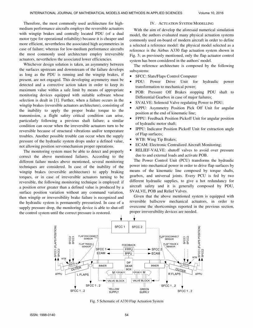
IV. ACTUATION SYSTEM MODELLING
With the aim of develop the aforesaid numerical simulation
model, the authors evaluated many physical actuation systems
commonly used on-board of modern aircraft in order to define
a selected a reference model: the physical model selected as a
reference is the Airbus A330 flap actuation system shown in
Fig. 5; as previously mentioned, only the flap actuator control
system has been considered in the authors' model.
The reference architecture is composed by the following
subsystems:
• SFCC: Slats/Flaps Control Computer
• PDU: Power Drive Unit for hydraulic power
transformation to mechanical power;
• POB: Pressure Off Brakes stopping PDU shaft to
Differential Gearbox in case of major failures;
• SVALVE: Solenoid Valve regulating Power to PDU;
• APPU: Asymmetry Position Pick Off Unit for angular
position at the end of kinematic line;
• FPPU: Feedback Position Pickoff Unit for angular position
of hydraulic motor shaft;
• IPPU: Indicator Position Pickoff Unit for extraction angle
of Flap surfaces;
• WTB: Wing Tip Brakes;
• ECAM: Electronic Centralized Aircraft Monitoring;
• RELIEF-VALVE: shutoff valves to avoid over pressure
due to and external loads and activate POB.
The Power Control Unit (PCU) transforms the hydraulic
power into mechanical power in order to drive flap surfaces by
means of the kinematic line composed by torque shafts,
gearbox, and universal joints. Every PCU is fed by two
different hydraulic supplies, to give a hot redundancy for
aircraft safety and it is generally composed by PDU,
SVALVE, POB and Relief Valves.
Given that the above mentioned system is equipped with
reversible ballscrew mechanical actuators, in order to
overcome the shortcomings reported in the previous section,
proper irreversibility devices are needed.
Fig. 5 Schematic of A330 Flap Actuation System
INTERNATIONAL JOURNAL OF MATHEMATICAL MODELS AND METHODS IN APPLIED SCIENCES Volume 10, 2016
ISSN: 1998-0140 54

In particular, as shown in Fig. 5, the irreversibility of the
whole transmission is performed by means of two wing-tip
brakes located at the two outer ends of the shaft system. When
a mechanical transmission break occurs (in reversible
systems), in order to stop the flap surfaces for each wing (and
limit the corresponding asymmetry), the monitoring and
control system engages the WTB friction disks, reducing the
input pressure of the hydraulic Power Supply, in order to
develop a proper braking torque.
Although the WTB is the common used irreversibility
system, its asymmetry performances in case of major failure of
torque shaft fracture could result unreliable under particular
flight conditions (e.g. conditions of very high aerodynamic
load), especially using simple asymmetry control based on
differential position monitoring [1]. It should be noted that, in
case of catastrophic transmission failure, the performance
given by the actuation system equipped with WTB could be
improved by implementing more effective flap asymmetry
monitoring techniques [1-3].
V. PROPOSED NUMERICAL MODEL
As previously described, the primary goal of this work is to
propose a numerical simulation model, developed in the
Matlab/Simulink® environment, able to simulate a modern
flap actuation control system, described in the above
paragraphs, improving WTB architecture with innovative
monitoring and control algorithm. It must be noted that the
characteristics of the proposed simulation model (i.e. modular
layout and multi-domain physical-based parametric modelling)
allows simulating various flap actuation system configurations
taking into account different operating conditions.
Moreover, it allows to test innovative layout solutions and
to evaluate the performance and the robustness of new
monitoring techniques (using the proposed model as a suitable
numerical test-bench in order to support the decision making
process during design activities). As previously mentioned, in
this work a specific aircraft (i.e. A330) has been considered as
reference model for the flap actuation system in order to define
the set of physical parameters and boundary condition able to
adapt the dynamic responses of the proposed numerical model
with the real system ones. In particular, this reference allows to
identify (and collect) the different technical data related to:
• Geometries of main components (e.g. Flap surfaces, torque
shafts, irreversibility brakes, gearboxes);
• Operative flight conditions (e.g. takeoff, approach and
landing phases): using to define aerodynamic loads
working on the flap system;
• Operative parameters of main actuation system components
(e.g. transmission stiffness, mechanical backlashes,
material characteristics, bearings and hinges friction
coefficients).
Furthermore, dedicated design algorithm are developed to
customize NBB solution for different aircraft configuration as
a reference system to evaluate classical WTB solutions
improved by innovative monitoring and control techniques.
The numerical model reported in Fig. 6 is consistent with
physical model described in the previous paragraph (Fig. 5).
It is composed of nine subsystems:
1) Com: an input block that generates surface position
commands (Com);
2) SFCC: subsystem simulating the Slat/Flaps Control
Computer functions (e.g. a PID controller closing the
position loop) and the related Monitoring and Asymmetry
Control Algorithms; this block generates as output a
command signal for control system of servovalve (SV) [2];
3) Flapper-Nozzle SV: third order electromechanical model to
calculate SV spool displacement as a function of SFCC
command signals [4];
4) Fluid Dynamic SV Model: fluid dynamic model to
correlate spool displacement XS to differential pressure
P12 and flow rate QJ managed by SV [5-6];
5) PSR: supply pressure generated by electrohydraulic pump;
6) PDU: second order numerical model simulating the global
power drive units behaviors [3]; it is able to calculate the
mechanical power generated by the hydraulic motors
taking into account inertia, elastic torque acting on each
transmission line, viscous damping, internal friction
phenomena and differential pressure supplied by hydraulic
systems;
7) Transmission Model: motion transmission model
evaluating backlash and stiffness of torque shaft and
universal joint and gear boxes, detailing specific
parameters for left and right line;
8) TRL,TRR: Value of aerodynamic loads acting both left and
right flap surfaces;
9) Left/Right Surface-Actuator: Left/Right Surface-Actuator:
second order numerical model that simulates the dynamic
response of flap surfaces and ballscrew actuators taking
into account static and dynamic friction phenomena and
main features of WTB and NBB systems.
Some nonlinear phenomena need to be managed by the
numerical simulation model in order to improve accuracy state
by means of particular dedicated simulation algorithms. In our
proposed simulation model we manage different nonlinear
physic phenomena as static and dynamic Coulomb’s friction,
backlashes, stiffness and viscous dumping and transient
hydraulic behavior [7]. For each nonlinear phenomenon a
specific numerical approach is defined and integrated within
some model subsystems, leaving aside, where is possible, a
massive integration related to a more complex numerical effort
avoiding a negligible effect on model behaviors. As previously
reported, the proposed numerical model has been developed
taking into account various researches available in literature; it
must be noted that, in terms of numerical modelling, this paper
proposes original contributions related to the implementation
of the mechanical subsystems (kinematic transmission chain
and surface actuators), the development of the different control
logics (e.g. multidomain flap asymmetry monitoring
implemented by means of Stateflow/Simulink state machines)
and the integration of the different contributions/subsystem.
INTERNATIONAL JOURNAL OF MATHEMATICAL MODELS AND METHODS IN APPLIED SCIENCES Volume 10, 2016
ISSN: 1998-0140 55

Fig. 6 Proposed MATLAB/SIMULINK® simulation model of flap actuation system
In particular, in the next part of this chapter, will be
presented the numerical models developed by the authors to
simulate the dynamic behavior of the mechanical items of the
flaps transmission line. It must be noted that the mechanical
items of the flaps transmission line play an important role in
the achievement of the authors' goals because the
performances of the whole flap actuation model (sensibility,
accuracy, robustness and computational burden) are
significantly influenced by the quality of the modeling of the
mechanical parts. The “Torque Shaft Transmission”,
schematically shown in Fig. 7, simulates the behavior of the
whole mechanical transmission: it must be noted that this
subsystem is a simplified lumped numerical model simulating
the dynamic behavior of the transmission chain (composed by
the speed reducer gearboxes and the torque shafts linked
together by universal joints). In this numerical model, the
whole kinematic line is divided in three subsections
representing the high, medium and low speed sections of the
physical subsystems: gearmotor model as fast shaft,
mechanical transmission model as intermediate shaft and
surface-actuators as low shaft. By means of proper
conversions, all torque calculations are elaborated within the
intermediate shaft so we consider these gear ratios related to
speed reducers: ZM from fast shaft to intermediate shaft, ZS
from the intermediate shaft to low shaft. As Shown in(1) and
(2), the mathematical model of the mechanical transmission is
calculated as a function of the gearmotor angular position θM
and the deflection surface angle θS (reduced to the same drive
shaft); it must be noted that, within the proposed Simulink
numerical model, the first angle is indicated as ThM, while the
second one is referred as ThSL for left surface and ThSR for
right surface. Given that the transmission lines could be
affected by mechanical backlashes, the proposed numerical
model is able to simulate their effects by means of lumped
parameters BLG: as shown in Fig. 7, for each wing the
corresponding torque dead bands is calculated in (1) as a
function of deformation angle θTrasm.
(1)
(2)
The torque CTrasm, transmitted by the mechanical shaft is
calculated in (3) as sum two terms: an elastic term,
proportional to the transmission differential torsion by means
of an elastic stiffness coefficient KG (4), and a viscous one,
proportional to the differential angular velocity of the
transmission by means of a damping coefficient CG (5),
representing hysteresis behavior of the material used for
transmission components when the aforesaid deformation
speed is different than zero.
(3)
(4)
(5)
The parameter IRG is a Boolean value used by the authors
to simulate the torque shaft failure (in nominal condition it is
set to 1 but, in case of transmission break, assumes null values
in order to simulate the annulment of the transmitted reaction
torque following the breaking of the kinematic chain).
As shown in (6), the aforesaid stiffness coefficient KG is
composed by two different terms considering an arbitrary
division of kinematic line useful to introduce the effects of the
system within the transmission model.
In particular, the coefficient KMin represents the equivalent
stiffness of portion of mechanical transmission between the
PDU torque output and the mechanical input of the surface
actuator, while the coefficient KMout is related to the
equivalent stiffness of the transmission downstream the said
actuator input.
(6)
INTERNATIONAL JOURNAL OF MATHEMATICAL MODELS AND METHODS IN APPLIED SCIENCES Volume 10, 2016
ISSN: 1998-0140 56

Fig. 7 Block diagram of the mechanical transmission model
(left and right transmission lines) equipped with WTBs
By means of an analogous approach it is simulated
simulated the CG viscous elastic coefficient as indicated in (7):
(7)
Therefore, the mechanical transmission model of the flap
actuation system equipped with WTBs has been modelled as
shown in Fig. 8. Vice versa, in order to simulate a flap
actuation system equipped with NBBs, it is necessary to
consider the effects of this irreversibility device on the
equivalent values of stiffness and viscous dumping of the
transmission system: indeed, the insertion of the no-back
brake, because of its elastic compliance, modifies the
equivalent stiffness of the kinematic line. As reported in (8),
the equivalent stiffness of the mechanical transmission
equipped with MBBs are then modelled introducing another
term KNB representing the NBB elastic compliance.
(8)
(9)
Furthermore, in this case the elastic torque acting on the flap
mechanical transmission is expressed as a function of two
different components: the first one, as shown in (9), represents
the elastic reaction of the kinematic line (having torsional
stiffness KGNBB) under the effects of a given torsional
deformation θTrasm, while the second, expressed in (11), takes
into account the internal stiffness of the brake spring KNBF
explained in (10).
(10)
(11)
Similarly the viscous elastic dumping coefficient CG is
modified by the presence of NBB introducing an additional
term CNB related to viscous elastic damping between input
and output of NBB component.
Fig. 8 Block diagram of the mechanical transmission model
(left and right transmission lines) equipped with NBBs
(12)
(13)
Another effect due to the introduction of the NBB within
flap actuation systems is the internal backlashes of NBB
mechanism: it is simulated by means of a coefficient ThTF
which represents the amplitude of a dead band linked to Celast2
and expressed as a function of the internal springs deformation
angle θNBB; within this band also Celast1 has zero value.
Therefore, as shown in Fig. 8, the numerical model
representing the transmission equipped with NBBs takes into
account two different backlash type: the first term (called
BLG) is shown in (14) and, similarly to the case of systems
with WTBs, takes into account the backlashes affecting the
mechanical transmission, while the second one (ThTF),
reported in (15), evaluates the effects of the eventual NBBs
internal backlashes.
(14)
(15)
An important nonlinear physics behavior simulated in this
numerical model is related to the Coulomb’s friction
phenomena. The analysis elaboration for a robust friction
model must mathematically describe the physical phenomenon
distinguishing between the four possible conditions:
• mechanical element initially stopped which must persist in
standstill condition;
• mechanical element initially stopped which must break
away;
• mechanical element initially moving which must persist in
movement;
• mechanical element initially moving which must stop.
This ability is important, especially in order to point out
some specific behaviors concerning the moving parts of
whatever mechanical system characterized by dry friction,
large displacements and speeds, forward-backward movements
and eventual standstill or stick-slip conditions.
INTERNATIONAL JOURNAL OF MATHEMATICAL MODELS AND METHODS IN APPLIED SCIENCES Volume 10, 2016
ISSN: 1998-0140 57

According to these considerations, the ability to select the
correct friction force sign as a function of the actuation rate
sense, to distinguish between the sticking condition (static) and
the slipping (dynamic) one, to evaluate the eventual stop of the
previously running mechanical element, to keep correctly in a
standstill condition the previously still mechanical element or
to evaluate the eventual break away of the previously still
element itself must be considered as the most relevant merit.
In aeronautical field, such problems are strictly inherent in
servomechanism behavior analysis and so it is particularly
interesting to employ these numerical methods in the
simulation of their dynamics.Many authors have developed
models to simulate static and dynamic Coulomb’s friction
forces as Stribeck, Karnopp, Quinn et al. [8-11].
All these models give simulations not corresponding to the
real behavior, manifesting problems of “zero crossing
velocity” between static and dynamic friction, or using the
values of the main parameters arbitrarily defined by the users
which make these models not reliable [12] or, even, make
them cause of numerical instability (e.g. the numerical limit
cycles, attributable to incorrect identification of the transition
between static and dynamic conditions, that characterize the
dynamic response of mechanical systems simulated by
numerical algorithms that use the SIGN friction model) [13].
In order to avoid the aforesaid numerical problems, the
authors have integrated the friction algorithm proposed by
Borello et al. [14] (shown in Fig. 9) into the subsystems
simulating the dynamic behavior of the different mechanical
items. This friction model is based on these variables:
• FSJ: Static Friction Force;
• FDJ: Dynamic Friction Force;
• FF: Resultant Friction Force;
• DThSL: Speed Transmission Line;
• DThSL SP: Reference value (not reset) of DThSL;
• ActTh: Active Force on actuator surface system.
The breaking condition imposed by the model in case of
zero crossing of the actuation speed, in case of left wing
transmission, is shown in (16):
(16)
in which DThSL SP is the reference rotational speed of the
transmission subsystems, calculated during the previous
integration time and used to perform the aforesaid zero-
crossing detection. It must be noted that, if the sticking state
imposed by (16) doesn't result a static condition (because the
so calculated static friction force is not able to equilibrate the
active forces acting on the dynamic system), the comparison
between the active and the friction forces acting on the
dynamic system would cause its breakaway in the following
integration time (incipient motion conditions).
In order to guarantee suitable levels of accuracy and fidelity,
the Borello friction algorithm is directly implemented in the
numerical models simulating the dynamic response of the
mechanical components of the flap actuation system;
specifically, it is integrated within the numerical models of
PDU hydraulic motors, gearboxes and actuators.
Fig.9: Block Diagram of Reference Friction Model
The actuator surface model considers dynamic equilibrium
equation (17) among Act active torques, Cres resistant torques,
CIN inertia component as a function of angle, speed,
acceleration of flap surface.
(17)
(18)
(19)
The frictional torques developed by WTBs or NBBs are
evaluated by a dedicated algorithm able to take into account
their effects and the eventual interactions with the
corresponding mechanical systems. Given that several braking
systems have been considered, the authors developed different
specific simulation models. A design process aimed to define
the braking torque developed by the irreversibility brakes
provides the operating parameters of the simulation model.
The NBBs are modelled by means of a simplified model
implemented in Simulink through a lookup table: the braking
torque FFnoback is calculated as a function of the driving net
torque ∆TG (for instance, considering the left wing
transmission, the aforesaid net torque is calculated as a
difference between the driving torque TGL and the
corresponding aerodynamic external load TRL).It must be
noted that in case of positive values of ∆TG the NBB gives a
minimum constant torque value FF_NBBmin in every motion
condition. Vice versa, when ∆TG takes negative values, the
corresponding braking torque evolves according to Fig. 10.
Fig.10 NBB Braking Torque as a function of ∆TG
INTERNATIONAL JOURNAL OF MATHEMATICAL MODELS AND METHODS IN APPLIED SCIENCES Volume 10, 2016
ISSN: 1998-0140 58

Fig.11 WTB Braking Torque as a function of PSR
The WTBs are similarly simulated by means of a “Simulink
Lookup Table” in which the braking torque is calculated (by
means of a simplified model) as a function of pressure supply
value PSR within the hydraulic circuit driving the WTBs.
The friction discs of the WTBs begin to develop a braking
torque when the flap control system commands the braking by
closing the dedicated relief valves. When the flap control
system activates the WTB, the PSR time transient is simulated
by first order model transfer function from nominal value of
PSR to PSVc minimum hydraulic pressure to apply a braking
torque, as indicated in Fig. 11.
The Simulink subsystem that implements the proposed
integrated reference friction model is shown in Fig.12; it is
able to calculate the global braking torque as sum of two
components respectively related to the frictional effects on
mechanical transmission and NBBs.
Fig.12: Block diagram representing the NBBs braking torque
algorithm integrated into the reference friction model.
VI. AIRCRAFT AND AUTOPILOT MODELLING
In order to assess the amount of perturbations induced on
the aircraft attitude by the failures of the flap actuation system,
also the lateral-directional dynamics of the aircraft and of its
autopilot has been simulated. The dynamics characterizing the
aircraft lateral-directional behavior is represented by the
usually considered model reported in the current literature
[15]. The autopilot control laws have been assumed to be of a
PID type, which is adequate to approximate the actual
autopilot control within the objective of the present work.
By measuring the aircraft roll angle the autopilot PID
controller develops the commands to the ailerons and to the
rudder. These flight controls have in turn been simulated as
second order systems having speed and position saturations
[3]. The aircraft data taken for the simulations are typical of a
commercial transport jet aircraft; the purpose of this selection
is purely exemplifying, because the aircraft behavior following
the failure is substantially similar for all the types of aircrafts.
VII. MONITORING ASYMMETRY TECHNIQUES
The current monitoring technique is based on the detection
of the differential position between left and right flap surfaces.
Its use generally slightly reduces the asymmetry, but in some
cases it may have an unreliable behavior [1]. To overcome
these shortcomings different monitoring strategies have been
developed by the authors in [2]. The assessment of their
effectiveness has been performed using the aforesaid Simulink
test bench, evaluating the ability of the different techniques to
limit the asymmetry following a torque shaft fracture.
For this purpose, the standard PID controller has been
integrated with a numerical algorithm that implements several
asymmetry monitoring techniques, characterized by an
increasing complexity and performances:
• Differential position control (type 1).
• Differential position and speed control (type 2).
• Differential position and speed conditioned control (type
2a).
• Differential position and speed proportional control (type
2c).
• Differential position and speed variable conditioned
control (type 2d).
The differential position control technique, referred as
asymmetry monitoring technique type 1, performs the flap
asymmetry detection by comparing the electrical signals of the
position transducers placed at the ends of left and right shaft
subsystems. If this difference is greater than a defined limit
∆θLim persisting for more than a given evaluation time, an
asymmetry failure is recognized and shut-off command
procedure is activated to engage the WTBs. The improved
asymmetry monitoring techniques, which are belonging to the
type 2 monitoring family, are based on detecting both position
and speed differences of the two ends of the transmission line
[1-3]. If either the position or the speed differential exceeds its
established reference threshold for more than a given
evaluation time, then an asymmetry is recognized.
VIII. SIMULATION RESULTS
In order to evaluate the performance of the proposed
numerical model and its ability to test the aforesaid monitoring
techniques, several simulations have been run simulating a
mechanical failure of the transmission shaft with a resulting
asymmetry between right and left surfaces. It must be pointed
out that the asymmetries obtained in case of large loads are
always higher than the low load ones [1]; therefore in the
present work only loaded actuations are considered.
INTERNATIONAL JOURNAL OF MATHEMATICAL MODELS AND METHODS IN APPLIED SCIENCES Volume 10, 2016
ISSN: 1998-0140 59
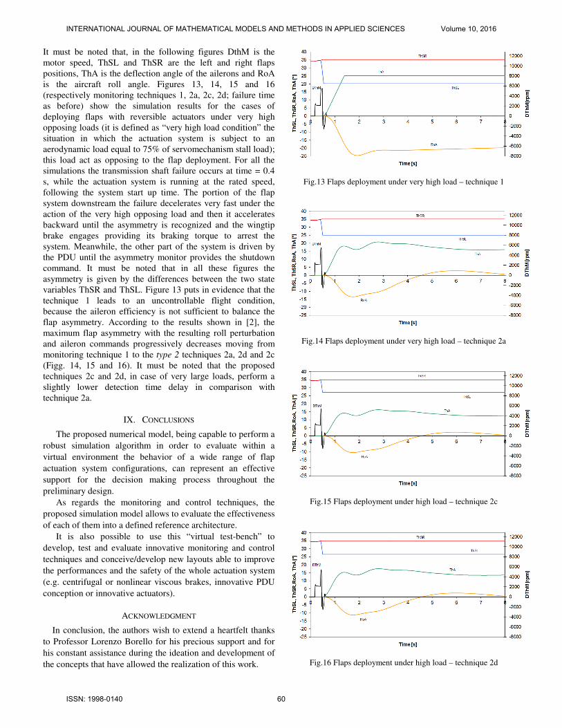
It must be noted that, in the following figures DthM is the
motor speed, ThSL and ThSR are the left and right flaps
positions, ThA is the deflection angle of the ailerons and RoA
is the aircraft roll angle. Figures 13, 14, 15 and 16
(respectively monitoring techniques 1, 2a, 2c, 2d; failure time
as before) show the simulation results for the cases of
deploying flaps with reversible actuators under very high
opposing loads (it is defined as “very high load condition” the
situation in which the actuation system is subject to an
aerodynamic load equal to 75% of servomechanism stall load);
this load act as opposing to the flap deployment. For all the
simulations the transmission shaft failure occurs at time = 0.4
s, while the actuation system is running at the rated speed,
following the system start up time. The portion of the flap
system downstream the failure decelerates very fast under the
action of the very high opposing load and then it accelerates
backward until the asymmetry is recognized and the wingtip
brake engages providing its braking torque to arrest the
system. Meanwhile, the other part of the system is driven by
the PDU until the asymmetry monitor provides the shutdown
command. It must be noted that in all these figures the
asymmetry is given by the differences between the two state
variables ThSR and ThSL. Figure 13 puts in evidence that the
technique 1 leads to an uncontrollable flight condition,
because the aileron efficiency is not sufficient to balance the
flap asymmetry. According to the results shown in [2], the
maximum flap asymmetry with the resulting roll perturbation
and aileron commands progressively decreases moving from
monitoring technique 1 to the type 2 techniques 2a, 2d and 2c
(Figg. 14, 15 and 16). It must be noted that the proposed
techniques 2c and 2d, in case of very large loads, perform a
slightly lower detection time delay in comparison with
technique 2a.
IX. CONCLUSIONS
The proposed numerical model, being capable to perform a
robust simulation algorithm in order to evaluate within a
virtual environment the behavior of a wide range of flap
actuation system configurations, can represent an effective
support for the decision making process throughout the
preliminary design.
As regards the monitoring and control techniques, the
proposed simulation model allows to evaluate the effectiveness
of each of them into a defined reference architecture.
It is also possible to use this “virtual test-bench” to
develop, test and evaluate innovative monitoring and control
techniques and conceive/develop new layouts able to improve
the performances and the safety of the whole actuation system
(e.g. centrifugal or nonlinear viscous brakes, innovative PDU
conception or innovative actuators).
ACKNOWLEDGMENT
In conclusion, the authors wish to extend a heartfelt thanks
to Professor Lorenzo Borello for his precious support and for
his constant assistance during the ideation and development of
the concepts that have allowed the realization of this work.
Fig.13 Flaps deployment under very high load – technique 1
Fig.14 Flaps deployment under very high load – technique 2a
Fig.15 Flaps deployment under high load – technique 2c
Fig.16 Flaps deployment under high load – technique 2d
INTERNATIONAL JOURNAL OF MATHEMATICAL MODELS AND METHODS IN APPLIED SCIENCES Volume 10, 2016
ISSN: 1998-0140 60

REFERENCES
[1] L. Borello, and G. Villero, “Mechanical failures of flap control systems:
proposal of advanced monitoring techniques,” International Journal of
Mechanics and Control, vol. 5, no. 2, 2004.
[2] L. Borello, G. Villero, and M. D. L. Dalla Vedova, “New asymmetry
monitoring technics,” Aerospace Science and Technology, vol. 13, no.
8, pp. 475–497, 2009.
[3] L. Borello, and M. D. L. Dalla Vedova, “Flaps Failure and Aircraft
Controllability: Developments in Asymmetry Monitoring Techniques,”
Journal of Mechanical Science and Technology (JMST), vol. 28, no.
11, pp. 4593–4603, November 2014.
[4] L. Borello, M. D. L. Dalla Vedova, and P. Alimhillaj, “Proposal of
Innovative Fluid Dynamic Nonlinear Servovalve Synthetic Models,”
International Journal of Mechanics and Control (JoMaC), vol. 14, no.
2, pp. 39–49, December 2013.
[5] F. Fraternale, A. Caimano, P. Maggiore, M. D. L. Dalla Vedova, and L.
Pace, “Comparative analysis of a hydraulic servo-valve,” International
Journal of Fluid Power, vol. 14, pp. 53–62, 2013.
[6] M. D. L. Dalla Vedova, P. Maggiore, and L. Pace. “Proposal of
Prognostic Parametric Method Applied to an Electrohydraulic
Servomechanism Affected by Multiple Failures,” WSEAS Transactions
on Environment and Development, pp. 478–490, 2014.
[7] M. D. L. Dalla Vedova, P. Maggiore, G. Jacazio, and M. Sorli, “A
prognostic model for electrohydraulic servovalves,” in Annual
Conference of the Prognostics and Health Management Society, pp.
478–490, 2009.
[8] D. Karnopp, “Computer simulation of stick-slip friction in mechanical
dynamic systems,” Journal of Dynamic Systems, Measurement and
Control, vol. 107, pp. 100–103, March 1985.
[9] D. D. Quinn, “A new regularization of Coulomb friction,” Trans. Of
ASME: Journal of Vibration and Acoustics, vol. 126, no. 3, pp. 391–
397, 2004.
[10] R. Kikuuwe, N. Takesue., A. Sano, H. Mochiyama, and H. Fujimoto,
“Fixed-step friction simulation: from classical coulomb model to
modern continuous models,” in International Conference on Intelligent
Robots and Systems IEEE/RSJ 2005, pp. 3910–3917, June 2005.
[11] D. Guida, F. Nilvetti, and C. M. Pappalardo, “Dry Friction Influence on
Inverted Pendulum Control,” in Selected Topics on Applied
Mathematics, Circuits, System, and Signals, Athens, 29–31 December
2009, pp.49–54. ISBN:9789604741472
[12] L. Borello, and M. D. L. Dalla Vedova, “Load dependent coulomb
friction: a mathematical and computational model for dynamic
simulation in mechanical and aeronautical fields,” International
Journal of Mechanics and Control (JoMaC), vol. 7, no. 1, pp. 19–30,
2006.
[13] D. Guida, F. Nilvetti, and C. M. Pappalardo, “Instability Induced by Dry
Friction,” International Journal of Mechanics, vol. 3, no. 3, pp. 44–51,
2009. ISSN:1998-4448.
[14] L. Borello, and M. D. L. Dalla Vedova, “A dry friction model and robust
computational algorithm for reversible or irreversible motion
transmission,” International Journal of Mechanics and Control
(JoMaC), vol. 13, no. 2, pp. 37–48, December 2012.
[15] B. Etkin, and D.R. Lloyd, Dynamics of Flight: Stability and Control,
John Wiley & Sons, 1982.
Dario Belmonte received the M.Sc. at Politecnico di Torino in 2011. Since
2011 he worked as assistant researcher at the Department of Mechanics and
Aerospace Engineering and GE Avio Aero srl. His research activity is mainly
focused on analysis and numerical simulation of dynamic systems and
aerospace servomechanism, integrating correlations between FEM and CAT (
experimental data) related to structural vibrational analysis for Gear Box and
Propulsor Turbine modules.
Matteo D. L. Dalla Vedova received the M.Sc. and the Ph.D. from the
Politecnico di Torino in 2003 and 2007, respectively. He is currently assistant
researcher at the Department of Mechanics and Aerospace Engineering. His
research activity is mainly focused on the aeronautical systems engineering
and, in particular, is dedicated to design, analysis and numerical simulation of
on board systems, study of secondary flight control system and conception of
related monitoring strategies and developing of prognostic algorithms for
aerospace servomechanism.
Paolo Maggiore is a professor at the Mechanical and Aerospace Engineering
Department of Politecnico di Torino, that joined in 1992, where he teaches
aerospace general systems engineering. Currently his assistant researchers and
PhD students are involved in projects ranging from hydrogen fuel cell
powered airplanes and UAVs, and health monitoring of flight controls, to
multi-disciplinary design optimization of aerospace systems design.
INTERNATIONAL JOURNAL OF MATHEMATICAL MODELS AND METHODS IN APPLIED SCIENCES Volume 10, 2016
ISSN: 1998-0140 61