Flight Evaluation of Advanced Controls and Displays for Transition ...

1
Aircraft Controllability and Primary Flight Displays
- A Human Factor Centered Approach By Knut Lande General Manager/Flight Safety Advisor LandAvia Ltd www.landavia.no October 2013 Summary The global air accident rate has gradually decreased during the last decades. During the 1990’s Controlled Flight into Terrain (CFIT) and Approach and Landing Accidents (ALA) were the “biggest killers”1 in aviation. Continuous focus and efforts by the airlines, manufacturers, and not least Flight Safety Foundation, has succeeded in reducing this type of accidents. However, today the “biggest killer” has changed to be Loss of Control in the air type of accidents (LOC-I). When analyzing these accidents we find that lack of pilot knowledge and skills quite often are significant cause factors. It seems that the development in aviation technology and automation has made the aircraft so reliable and the flying so automated that the pilots are left out of the loop. During routine flight this works fine, but if unexpected situations are encountered the pilots are not capable of handling flight situations “old timers” would call “basic flying” situations. The improvements in aeronautical technology might have had a negative effect on pilot education and training. Aircraft manufacturers and aviation authorities may also have contributed to this trend by advertising “low workload” cockpits and less required pilot training. Reduced focus on aerobatic flight and unusual attitude recovery training, combined with more automation, may have influenced basic piloting skills. Even though modern flight deck design is overall improved, there might have been some loss in instrument readability/interpretability during unexpected upset flight conditions and unusual attitude recovery. Using today’s technology, flight displays could be made more intuitive and easier to read in an unexpected and blurred flight situation. Also, by making flight control inceptors more intuitive, and thus improve tactile feedback cues, the pilots may be kept in the loop and be more prepared to take control in an unexpected situation. Several LOC accidents are related to aircraft stall. This may be an indication that the state-of-the-art Primary Flight Displays (PFD) are not presenting the aircraft flight condition in a most intuitive way, and not presenting the pilot with a clear indication of Angle of Attack (AOA). 1 Expression used by Flight Safety Foundation

2
Further, it may indicate that the pilot knowledge and skill in basic stall and upset recovery are insufficient. During this author’s 35 years as a member of SETP there have been many presentations and many papers on aircraft controllability. However, there have not been many SETP presentations or papers on PFD research and testing. An aircraft’s stability, control and handling qualities are very important to the pilot’s ability to control the aircraft. However, regardless of how ideal the aircraft’s handling qualities are, it is of limited value if the handling pilot becomes confused and disorientated during an unusual attitude (UA) or upset recovery (UR). Several of the recent accidents seem to be related to PFD’s and the pilots knowledge and training in interpreting their displays. It may be time for SETP to focus also on PFD’s in addition to aircraft handling qualities. Accident Statistics The global air accident statistics have gradually improved over the last 50 years (Fig. 1). This has mainly been caused by gradual improvements in aeronautical engineering and technological innovations. Examples on this are improved Weather Radars (WR), Navigation Displays (ND), Vertical Displays (VD), Traffic and Collision Avoidance Systems/Airborne Collision Avoidance System (TCAS/ACAS), Ground Proximity Warning System/Terrain Avoidance and Warning System/Enhanced Ground Proximity Warning System (GPWS/TAWS/EGPWS), Category II/III Landing Systems, etc.
Figure 1. Major accidents by decade (by courtesy of FSF).

3
During the 1990’s Controlled Flight into Terrain (CFIT) and Approach and Landing Accidents (ALA) were dominating accident categories (Fig. 2). These accidents were considered to be the “biggest killers in aviation” during the 1990’s.
Figure 2. CFIT accident statistics (provided by FSF).
The latest technological advancements, e.g. improved ND, VD, GPWS/TAWS/EGPWS helped reduce these categories of accidents. However, the reduction in CFIT accidents led to increased focus on Loss of Control in Flight (LOC-I) accident statistics which seems to remain high (Fig. 3).

4
Figure 3. LOC-I accident statistics (provided by FSF).
The common factors in most LOC accidents seem to be lack of pilot knowledge and piloting skills. David Learmount, Flight International, has stated (3 January 2012)2: http://www.flightglobal.com/news/articles/in-focus-airlines-run-up-a-safety-debt-365509/
“What has most affected the nature of pilots' work is the influence of low-cost carriers, which has brought radical change in many airlines' relationships with flight crew. But what has most changed an airline's crew recruiting and management is the decline of the military as a provider of pilot skills. Meanwhile, there has been a loss of pilot exposure to anything other than pre-packaged flight planning, followed by automated flight on the line. When circumstances are unusual, non-standard, or not automated, a resulting lack of pilot resilience has been leading to fatal loss of control (LOC) accidents, making LOC the biggest killer accident category this century - taking over from controlled flight into terrain in the last. This fact is acknowledged by industry bodies like the International Air Transport Association (IATA) and the International Civil Aviation Organisations (ICAO), respectively IATA's training and qualification initiative (ITQI) and ICAO's next generation aviation professionals (NGAP). So the carriers cannot say they have not been warned, but these efforts have not been translating into action at airline level. Just as a reminder, the number of fatalities caused by airline accidents in the 1980s was about 1,100 annually, whereas the numbers now are less than 800 a year despite the fact that the revenue passenger kilometers flown now are three times what they were then. The industry could revert to the bad old days, but for a different reason: now the aircraft are better, but the skills to operate them are degrading”.
2 Reference 14

5
It is the author’s opinion that the progress in modern Glass Cockpit and Flight Display design have improved the navigation task, but not contributed to improving pilots’ attitude in space situational awareness. It may be argued that some of the modern Flight Displays are not very intuitive or helpful in a loss of control situation. Further, the increased use of cockpit automation seems to have influenced the education and training of younger pilots. We have also seen that manufacturers advertise their airplanes as easy to fly (“low workload”) and unable to stall. Such statements are unrealistic and misleading to student pilots. Any student pilot should have a basic knowledge in physics and be taught from basic training that any heavier than air vehicle must always be aerodynamically controlled and may “fall out of the sky” if not the flight conditions producing a sustainable lift are maintained, i.e. a minimum airspeed, or more accurately, an Angle of Attack (AOA) below maximum allowable. Whether the airplane is stalling or out of control for other reasons does not matter. Even though todays accident rates in aviation are quite low, the latest LOC accidents are avoidable and seem to be caused by a combination of inefficient PFD’s and lack of knowledge and basic flying skills among the pilots. Some Typical LOC-I Accidents Stall during high altitude cruise West Caribbean Airways WCW708 (MD-82). Venezuela 2005 – high altitude stall (“coffin corner”) – climbed rapidly from 31,000 ft to 33,000 ft to avoid TS – altitude could not be sustained – on autopilot which gradually lifted the nose to hold altitude until AP disengaged and A/C entered a stall. Contributing cause factors: Allowed airspeed drop to stall speed - improper stall recovery - A/C held with aft stick in a (controllable) deep stall with engine climb power until crashing –pilots confused. http://avherald.com/h?article=4308e7d6&opt=0 Air France AF447 (A330-203). South Atlantic 2009 - high altitude stall after loss of IAS (“coffin corner”) – A/C held in a controllable deep stall with aft stick with engine climb power until it crashed in the sea. Contributing cause factors: Loss of control – not controlling attitude – allowed the A/C to stall – improper stall recovery – A/C held in controllable deep stall with climb power – pilots confused. http://www.bea.aero/docspa/2009/f-cp090601.en/pdf/f-cp090601.en.pdf http://www.youtube.com/watch?v=kERSSRJant0&feature=endscreen Stall during Approach

6
Colgan Air DHC-8-Q400. Buffalo, USA 2009 – stall during approach – went through stick shaker and pusher. Contributing cause factors: Improper stall recovery - overrode the pusher (by pulling) and entered a fatal spin to the right – pilots confused. http://www.ntsb.gov/doclib/reports/2010/AAR1001.pdf Turkish Airlines B737-800. Amsterdam 2009 – stall during final approach on autopilot with one radar altitude malfunctioning – stick shaker at 460 feet. Contributing cause factors: Improper stall recovery – too late recovery actions – pilots confused. http://www.skybrary.aero/bookshelf/books/1175.pdf Asiana Airlines B777-200ER San Fransisco 2013 – approach to stall during approach on autopilot. The aircraft “fell through” and hit the runway embankment nose high with stick shaker on. The accident investigation is ongoing, but based on public statements from the NTSB it may seem that contributing cause factors may be related to interpretation of flight displays and pilot experience – pilots confused. http://www.ntsb.gov/investigations/2013/asiana214/asiana214.html
“Airspeed eroded, despite six eyes on the Asiana 777 flight deck.3 Complications and distractions aside, over-reliance on automation systems appears to have trumped basic flying skills and crew resource management in the crash of Asiana Airlines Flight 214 at San Francisco International Airport on July 6. The accident will put additional pressure on an industry already grappling with implementing training and human-factors lessons learned from recent high-profile pilot-error-related accidents such as the 2009 Colgan Air Q400 loss-of-control crash in Buffalo, N.Y., and the Air France A330 accident off the coast of Brazil. In response to the Colgan accident, the FAA will soon publish a final rule requiring first-officer hires to have at least 1,500 hr. of flight time and an air transport pilot certificate and type rating, a six-fold increase compared to the 250 hr. and commercial pilot certificate minimums today. Meanwhile, avionics manufacturers are making headway on research to simplify the complex and often confusing human-machine interfaces that hinder rather than help pilots. Rockwell Collins is working on a project to reduce the number of federated automatic flight control (auto-flight) modes added to the flight deck. By aligning auto-flight modes with pilot "goals"-arriving at a certain point at a certain time with a
3 Curt Lewis & Associates, Flight Safety Information, July 15, 2013

7
given amount of fuel-researchers were able to design a prototype mode manager that effectively gives pilots seven auto-flight mode choices rather than as many as 38. Adding to the confusion are multiple modes for autot hrottle systems that link to complex auto-flight and autopilot systems. Auto throttles provide automatic speed or vertical speed control, including stall prevention in some modes, allowing pilots to focus on other tasks. According to Boeing documentation, the 777's autopilot has five operating modes. Mode confusion could have played a role in the Asiana crash -the pilot-in-command of the highly automated 777-200ER expected that the Boeing 's auto throttle system would hold the aircraft's approach speed to a preset value of 137 kt. as the aircraft, high on the initial approach, descended to capture a visual or electronic glideslope. The system did not maintain the speed, leaving the engines at flight idle through the final portions of the approach and placing the aircraft very near an aerodynamic stall less than 200 ft. above San Francisco Bay in a high-drag state with landing gear and flaps deployed to 30 deg. before pilots detected the error. The crew attempted a full-thrust go-around, but the call came too late, as the twinjet's main landing gear and tail clipped a seawall ahead of Runway 28L 1.5 sec. later.
Figure 4. Asiana Airlines Flight 214 (Internet 15 July 2013)4.
4 ASIANA 214 simulation Click here: (Internet 15 July 2013)

8
CHC AS 332L2 Super Puma Sumburgh Airport, Shetland Islands 2013 – loss of airspeed during final instrument approach – on autopilot in vertical speed mode – manual torque (power) – pitch attitude increased to 20° nose up and airspeed dropped below 30 KIAS, torque increased to 115 % with rate of descent increasing to 1,800 ft/min – pilots confused. The initial AAIB analysis showed that the combination of the nose-high attitude, low airspeed, high rate of descent and high power, placed the helicopter in a Vortex Ring State (VRS) entry condition during the final stages of the flight. The ongoing AAIB investigation will focus on the operational aspects of the flight; specifically on the effectiveness of pilot monitoring of instruments during the approach, operational procedures and the training of flight crews. http://www.aaib.gov.uk/cms_resources.cfm?file=/S7-2013%20AS332%20L2%20G-WNSB.pdf Accident summary These are just examples of recent LOC accidents. All of these accidents indicate pilot’s confusions and lack of basic aeronautical knowledge and flying skills. Most of the accidents are related to knowledge about angle of attack and stall recovery. The MD-82 and A330 accidents are related to lack of knowledge about flying in the “coffin corner” (Fig. 5), where the stall speed/mach is higher and maximum speed is lower, reducing the margin between Vmax (VMO/MMO) and Vstall. The Colgan, Turkish and Asiana accidents were all related to lack of air speed/high alpha control during approach, and subsequently stalled. They did not recognize the high alpha flight condition and were not able to prevent the accidents. We see that these types of accidents are not only related to fixed wing aircraft. While airplanes may stall and enter controllable deep stall, helicopters may enter (controllable) Vortex Ring State (VRS) which, from a piloting point of view, may be comparable to an airplane stall. The recovery is similar - nose down and increase power. Accident Investigations Historically, most LOC accidents were labeled «Pilot/Human Error». Professor Dr. Sidney Dekker offers two views on Human Error (2006)5: The Old View: “Human error is a cause of trouble” (Bad Apple Theory). The New View: “Human error is a symptom of trouble deeper inside a system”. Professor Dr. James Reason (1997)6:
5 Reference 15

9
”The Organizational model views human error more as a consequence than as a cause. Errors are the symptoms that reveal the presence of latent conditions in the system at large”. Dr. Simon Bennett (2012)7: “Malfunctions are to be expected in aircraft, by virtue of their interactive complexity, tight coupling and risk-and-error-prone operating environment. In the risk-laden world of aviation the pilot is the last line of defense”. In modern accident investigation theory Human Error is not considered a cause of accidents. LOC accidents have several underlying cause factors and most LOC accidents are Organizational Accidents. Coffin Corner When flying at high altitude the air density is low; hence lift and thrust are reduced. The airplane angle of attack is increased to compensate for the loss of lift. The mach number increases as a function of lower temperature. Thus the maximum cruise true airspeed (VMO) approaches the critical mach number (MMO) and must be reduced (mach buffet). At the same time, due to mach effects the stall speed/mach no increases. As the airplane climbs the cruise speed is gradually reduced and approaches the minimum flying speed or critical angle of attack (stall buffet). Hence, the margin between high mach buffeting and low speed buffeting becomes smaller and smaller with altitude. This flight conditions has been labeled the “coffin corner” due to the challenging flight conditions (Fig. 5). Hand flying at high altitude by reference to airspeed only is very challenging. It is very difficult to control the airspeed accurately and angle of attack is required for precise airspeed control.
Figure 5. Coffin Corner (Wikipedia 2012).
6 Reference 16
7 Reference 17

10
Aerodynamic Stall and AOA indicators Aeronautical knowledge about the relationship between angle of attack and flying speed, and the necessary training has been basic pilot knowledge and training requirement for decades. However, based on the recent LOC accidents it seems that the focus on stall theory and training has diminished. Aerodynamic stall occurs when the airspeed reduces below stall speed which varies according to flight conditions (Fig. 6). However, it is not the airspeed itself but the angle of attack which is the critical factor (Fig. 7). The airspeed is an indirect indication of the angle of attack in level flight. During maneuvering flight the wing will still stall at the CL Max but at a higher indicated stall speed. Hence, it is only in level flight the pilots have a good reference to the actual stall speed. An angle of attack indicator will give direct indication in relation to the stall angle of attack. This is basic pilot knowledge, but for some unknown reason the aircraft manufacturers and certifying authorities have been reluctant to include an angle of attack indicator as a primary flight instrument.
Figure 6. Aerodynamic Stall Figure 7. Airplane stall angle of attack (D. Carbaugh, Boeing 2010). (D. McKenney, ALPAI 2010).
Stalls can occur when performing any maneuver. The wing “does not know” about airplane attitude or airspeed (Fig. 8).
Figure 8. Stall during maneuvering (Wikipedia 2012).

11
The wing “stops flying” when the critical angle of attack is exceeded. Result is stall - and if not properly educated and trained, the pilot may lose control. An Angle of Attack (AOA) indicator which clearly and intuitively tells the pilot the margin to stall or minimum control may mitigate such loss of control. This is the most fundamental and basic knowledge the student pilots are required to know, and that the airspeed indicator is just an “aerodynamic indicator” which does not tell the pilot how much lift margin he has, but is related to the forces acting on the aircraft. This has been an item for discussion for several decades. Technically it is not complicated to install useable and intuitive angle of attack indicators in airplanes. This is merely a policy issue. US Navy and some Air Force fighter airplanes have had alpha indicators installed for years, in addition to stall warning and artificial stall recovery systems. Some examples from the author’s personal experience related to flying with angle of attack indicators:
Figure 9. Examples of airplanes with angle of attack instruments (TA-4J, A-7D, F-104C/D, K. Lande).
Figure 10. Early block F-16A AOA indicator (Arun Karwal, NLR. Internet 2013).

12
Figure 11. A-10C AOA indicator (Internet 2013).
Pilots used to alpha indicators found these very intuitive and useful, showing the lift and performance margin in maneuvering and accelerated flight as well in approach and slow speed flight conditions. However, for unknown reasons it appears that FAA, EASA, Boeing and Airbus have been reluctant to provide pilots with this information. Reference 19 describes flight in the SR-71A Balckbird. The author makes several references to AOA and instrument displays. From ref. 19 are some citations:
“Practically all high-speed military jets have an angle of attack (AOA) indicator in the cockpit.” “AOA is an excellent indication of how well (or how poorly) an airplane is flying through the air.” “Until AOA indicators were developed, pilots had to know their aircraft’s flying characteristics at all gross weights, fuel loads, g-loads, flap settings, airspeeds, and other variables that affected the plane’s stall speed. An AOA indicator took all those variables into account and became a reliable indication of how well the aircraft was performing. In high-speed fighter aircraft, this development was a tremendous improvement because the pilot had only to check his AOA indicator to see how his aircraft is performing. Once an aircraft reached its critical AOA, it stalled.” “When I applied for the SR-71 program in 1973, part of the evaluation process at Beal consisted of two T-38 rides with an experienced SR-71 pilot making sure your flying skills and general airmanship were good. I had never flown the T-38 before and was

13
somewhat apprehensive about how the plane handled. My acceptance into the SR-71 program was riding on how well I could fly it. I distinctly remember my evaluator telling me to fly the T-38 just like it was an F-4 and to use the AOA. Once he said that, I flew it easily.”
As a result of the many LOC accidents in recent years, there is a growing interest in installing AOA indicators as part of the PFD. This author, just as many other military pilots of the “cold war era”, has flown several aircraft with AOA indicators. The experience gained is that AOA is a very intuitive primary flight indicator and just as valuable as the airspeed indicator. The author has read several comments from pilots not used to AOA indicators, supplemented by some test pilots caution against reliance on AOA indicators, with reference to inaccuracies and limitations. Extract from a Boeing article8:
“Angle of attack (AOA) is an aerodynamic parameter that is key to understanding the limits of airplane performance. Recent accidents and incidents have resulted in new flight crew training programs, which in turn have raised interest in AOA in commercial aviation. Awareness of AOA is vitally important as the airplane nears stall. It is less useful to the flight crew in normal operational range. On most Boeing models currently in production, AOA information is presented in several ways: stick shaker, airspeed tape, and pitch limit indicator. Boeing has also developed a dedicated AOA indicator integral to the flight crew’s primary flight display. AOA has been used as a primary performance parameter for years on some military aircraft, particularly on fighters. There are many good reasons for this. In general, fighters operate more often at the extremes of the envelope, often flying at maximum lift for minimum radius turns. For other applications, AOA minimizes the pilot (usually single-place) workload by giving a simple target to fly. AOA is accurate enough for these applications. In addition, the higher sweep and lower aspect ratio of the wing reduce the sensitivity to AOA errors. AOA has proved particularly useful for approach to aircraft carriers, where it is important to maintain a consistent approach attitude for each landing. In this case, “backside” approach techniques are used, where glide path is controlled primarily by changes in thrust while the aircraft is held at a fixed AOA. Use of this technique during approach on commercial jet airplanes would be contrary to the pitch commands provided by the flight director bars, and to the speed hold mode of the auto throttle, which is often used during approach.
8 John E. Cashman et al, Boeing article. Internet 2013

14
The last sentence is part of the problem. The mentioned technique is contradicting to basic aircraft flight mechanics and piloting principles. Student pilots learn the basic theory of controlling the AOA/airspeed with elevator and VSI by power during training.
Figure 12. Boeing AOA indicator (Boeing 2013).
AOA is measured on most modern aircraft and the data is used in the aircraft computers to calculate various flight parameters. Further, the AOA indication is of most importance when maneuvering or flying close to the stall AOA. Hence, the indication will be most useful during slow speed flight or during LOC and upset recoveries. Boeing is offering AOA indicator as an option (Fig. 12). However, this may not be the most efficient type of display. This author suggests that an AOA indicator should be a more prominent type of indicator.
Figure 13. Examples of AOA indicators (Internet 2013).
AOA indicators are becoming standard in civil experimental aircraft (Fig. 13):9
“After installation the unit is calibrated in the air during a short flight. There are two modes in which the AOA is measured: Flaps up and flaps down (15 degrees or more). Both are set at 1.15 x stall speed. At those speeds the audio warning, “Angle! Angle! Push!” will sound.
9 Cecil Rives, September 2004 Falco Builders Letter

15
I have flown with it now for about 100 hours and feel that I have greater “peace of mind” than I did before. I suppose you could call it a security blanket. I make my final approaches a little slower (65 knots over the fence), and I think make better landings. AOA is controlled by the elevator and rate of descent with the throttle. (I still keep one eye on the ASI, though). There have been a couple of instances when the aural warning of “Angle! Angle! Push!” has been heard on my headset. Nice to know someone is monitoring the AOA.”
Developments in Flight Displays LOC-I is not only related to pilot knowledge and training, but just as much to Flight Displays, Control Sticks and Levers (inceptors/thrust levers), in other words the Human – Machine – Interface. The author has been exposed to Flight Displays developed from the 1930’s to present day state of the art (by flying historic, vintage and state of the art aircraft). The experience is that standardization of flight instruments is less important to a pilot’s situational awareness and flight control. It is more important that the pilot “feels at home” in the cockpit and knows “blind folded” where the individual instruments and switches are located, and that the instruments are intuitive, easy to read and interpret. The author trained instrument flying in the two seats T-33 (Fig. 14) and flew operationally in the single seat RF-84F (Fig. 15). The difference did not matter as we were trained to cross check our instruments in a certain scan pattern (Fig. 30). Further, the flight instruments were similar in format and sizes, and one recognized the instruments from one aircraft to another, even though the location could differ.
Figure 14. Lockheed T-33A (K. Lande). Figure 15. Republic RF-84F (K. Lande).
It is worth noticing that we did not have a stand by attitude indicator available. To compensate we trained Partial Panel where the ADI was covered or disconnected (by circuit breaker).

16
Figure 16. Canadair CF-104 (Photo : Marc Bourque via K. Lande).
With the introduction of gyro stabilized inertial platforms the stand by attitude indicator became standard, but there was still no instrument layout standardization (Fig. 16). Note the large instrument sizes which made situational awareness in unusual attitudes easier. It is also worth mentioning the large AI with heading indication. With reference to just one indicator one got an instant “3D sense” of the flight attitude. This type of AI was used in several US aircraft, Apollo and Space Shuttle during the 1960’s and 1970’s. Compare this with today’s electronic ADI indicators which do not give the pilot the same “3D” sensation of “attitude in space”, but only gives a “flat 2D” impression of attitude. During the 1960’s the military Flight Displays became standardized. This was following the commercial flight deck standardization starting in the 1950’s10 (Fig. 17).
10
Reference 8

17
Figure 17. Northrop F-5A (1960’s) (T.O. 1F-5A-1 via K. Lande).
FAR 25 specified the flight instruments arranged in a T-shaped pattern, with the Attitude Director Indicator (ADI) in center, Horizontal Situation Indicator (HSI) below, airspeed located to the left of the ADI, altimeter to the right, with the vertical speed immediately below the altimeter. This arrangement became known as the “Basic–T”.
Figure 18. Douglas C-47 (1940’s) (K. Lande). Figure 19. Commercial Airliner (1970’s) (K. Lande).
Figures 18 and 19 show the development in flight displays in transport aircraft, from the non-standardized flight deck of a C-47 and the FAA standardized flight deck of a commercial airliner of the 1970’s. This standard “basic–T” 11 lay out is still a certification requirement for modern aircraft in FAR 25 and EASA CS-25 (Fig. 20). 11
Reference 13

18
Figure 20. Airbus standard flight display layout (Airbus).
We see that the relationship between the ADI and the other flight instruments are retained in the “basic–T” fashion. However, it may be argued that even if the scan distance is reduced, so is the instrument readability. Another aspect is the regulated installation of stand by instruments, but no associated requirement for training in use of these instruments12.
Figure 21. Conventional airspeed indicator (Wikipedia). Figure 22. State of the art airspeed indicator
(Wikipedia).
In an unusual attitude situation the old fashion round dial airspeed indicator is easy to read (Fig. 21), with large numbers, solid white needle pointer and a intuitive indication. With the pointer on the right hand side, a pull on the stick will increase the angle of attack and reduce
12
Reference 8

19
the airspeed. The approximate position of the pointer in relation to the position and color on the scale give the pilot an approximate sense of the airspeed and the lift margin in a glance, in addition to give the pilot a good rate of change in airspeed. The same type of instrument could just as well display AoA. The instrument would be intuitive in the sense that pulling on the control stick/yoke would increase/rotate the indicator needle to a higher digit and vice versa (pull-increase AOA, push-decrease AOA). What can be more intuitive to a pilot than pulling on the stick that increases the AOA/reduces the IAS, and pushing on the stick that decreases AOA/increases IAS. It is interesting to note the format developed by USAF in 1958, and introduced in operational aircraft such as F-105, F-106, F-111, C-141 and C-5 (Fig. 23). USAF research concluded that the airspeed scale digits should be increaseing downwards, i.e. “lower the nose, increase the airspeed” (“fly-to-principle”).
Figure 23. USAF Integrated Flight Instrument System (IFIS), 1958.13
On the other hand, the present state-of-the-art airspeed indicator (Fig. 22) is not intuitive, even if they have a “speed trend indicator”. This is not optimal as a rate indicator, especially in turbulence. The scale numbers are increasing upwards. This is opposite to raising the aircraft nose (pulling on the stick). From basic training every pilot is taught: raising the nose will decrease the speed and lowering the nose will increase the airspeed. Further, by raising the nose and hence reducing the airspeed, the moving scale should move downwards with decreasing digits from the top14. Therefore, the state-of-the-art airspeed
13
Reference 3 14
Reference 9
20
indicator is not intuitive and the vertical scale should be reveresed. Pushing the aircraft nose down would then result in increasing airspeed.
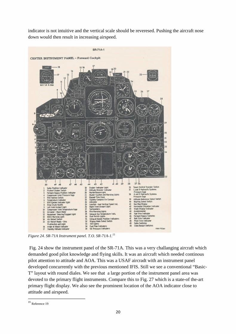
Figure 24. SR-71A Instrument panel. T.O. SR-71A-1.15
Fig. 24 show the instrument panel of the SR-71A. This was a very challanging aircraft which demanded good pilot knowledge and flying skills. It was an aircraft which needed continous pilot attention to attitude and AOA. This was a USAF aircradt with an instrument panel developed concurrently with the previous mentioned IFIS. Still we see a conventional “Basic-T” layout with round diales. We see that a large portion of the instrument panel area was devoted to the primary flight instruments. Compare this to Fig. 27 which is a state-of the-art primary flight display. We also see the prominent location of the AOA indicator close to attitude and airspeed. 15
Reference 19
21
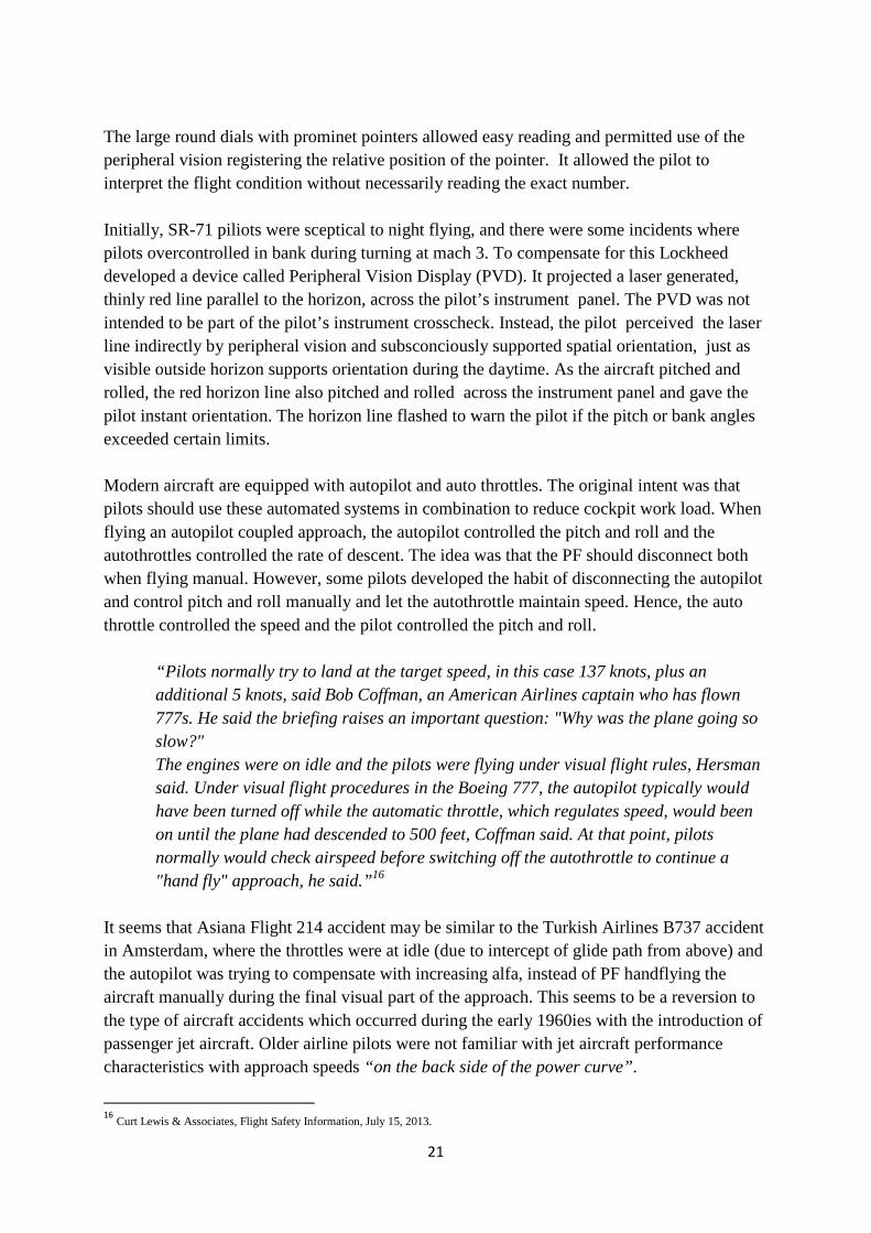
The large round dials with prominet pointers allowed easy reading and permitted use of the peripheral vision registering the relative position of the pointer. It allowed the pilot to interpret the flight condition without necessarily reading the exact number. Initially, SR-71 piliots were sceptical to night flying, and there were some incidents where pilots overcontrolled in bank during turning at mach 3. To compensate for this Lockheed developed a device called Peripheral Vision Display (PVD). It projected a laser generated, thinly red line parallel to the horizon, across the pilot’s instrument panel. The PVD was not intended to be part of the pilot’s instrument crosscheck. Instead, the pilot perceived the laser line indirectly by peripheral vision and subsconciously supported spatial orientation, just as visible outside horizon supports orientation during the daytime. As the aircraft pitched and rolled, the red horizon line also pitched and rolled across the instrument panel and gave the pilot instant orientation. The horizon line flashed to warn the pilot if the pitch or bank angles exceeded certain limits. Modern aircraft are equipped with autopilot and auto throttles. The original intent was that pilots should use these automated systems in combination to reduce cockpit work load. When flying an autopilot coupled approach, the autopilot controlled the pitch and roll and the autothrottles controlled the rate of descent. The idea was that the PF should disconnect both when flying manual. However, some pilots developed the habit of disconnecting the autopilot and control pitch and roll manually and let the autothrottle maintain speed. Hence, the auto throttle controlled the speed and the pilot controlled the pitch and roll.
“Pilots normally try to land at the target speed, in this case 137 knots, plus an additional 5 knots, said Bob Coffman, an American Airlines captain who has flown 777s. He said the briefing raises an important question: "Why was the plane going so slow?" The engines were on idle and the pilots were flying under visual flight rules, Hersman said. Under visual flight procedures in the Boeing 777, the autopilot typically would have been turned off while the automatic throttle, which regulates speed, would been on until the plane had descended to 500 feet, Coffman said. At that point, pilots normally would check airspeed before switching off the autothrottle to continue a "hand fly" approach, he said.”16
It seems that Asiana Flight 214 accident may be similar to the Turkish Airlines B737 accident in Amsterdam, where the throttles were at idle (due to intercept of glide path from above) and the autopilot was trying to compensate with increasing alfa, instead of PF handflying the aircraft manually during the final visual part of the approach. This seems to be a reversion to the type of aircraft accidents which occurred during the early 1960ies with the introduction of passenger jet aircraft. Older airline pilots were not familiar with jet aircraft performance characteristics with approach speeds “on the back side of the power curve”.
16
Curt Lewis & Associates, Flight Safety Information, July 15, 2013.

22
“The instructor pilot told investigators that at 500 ft. altitude, he realized the aircraft was below the PAPI's visual glideslope and told the left seat pilot to "pull back" on the control yoke. "He had set the speed at 137 kt. and assumed the autothrottles were maintaining the speed," the NTSB says. Depending on the auto-flight mode selected, autothrottles, if armed and turned on, should automatically control engine thrust to maintain a preset speed, in this case 137 kt., the reference landing speed for the 777-200ER that day.”17
This control technique is opposite of basic piloting principle, and eventually the pilots may develop a habit of controlling the aircraft’s vertical flight path in this manner. We may also see the effect of this habit in the AF447 accident, where the PF was pulling on the control stick (in stead of lowering the nose) and adding full thrust and thus “fly out of the high AOA condition”. This would be in line whith his previous training with Airbus systems, where he normally is protected by autothrust if approaching stall AOA. Hence, an AOA indicator should be a mandated supplement to the airspeed indicator, and by the same token it would be logical to have an airspeed scale with decreasing digits with increasing stick pull (“fly to - principle” ), or even better, a round dial as shown in Fig. 21. The combination of intuitive flight displays and controls (inceptors) should be related to basic flight principles learned during basic pilot training. The digits on state-of-the-art flight instruments might also be smaller than previously and not so easy to read in a “blurred” situation and dynamic flight (LOC) situation. The same may be said about the altimeter and vertical speed scales. Such scales are more suited to computers than to aircraft displays. These types of displays were introduced during the 1980’s and were driven by the avionics manufacturers. I have seen limited research reports documenting the benefits and efficiency of the modern flight display indicators, other than engineering and cost benefits18. According to available literature regarding vertical scale instruments and movement, the benefits of todays flight displays in a LOC situation is doubtful19. I am convinced that modern glass flight displays have improved the horisontal navigation and helped reduce CFIT accidents. However, they are less intuitive and efficient in resolving the pilots sense of the “3D attitute in space” in a LOC situation (unusual attitude or upset situation), and may have contributed to some of the recent LOC accidents. With todays digital technology it should be possible to design more functional and intuitive Flight Displays.
17
Curt Lewis & Associates, Flight Safety Information, July 15, 2013. 18
References 7 and 9 19
References 4, 5, 7 and 9

23
Figure 25. Cirrus SR-22 (Cirrus).
The future flight displays might be something similar to Fig. 25, displaying a synthetic picture of the outside world. The effect will be much the same as looking through a Head-Up-Display (HUD). The effect will be more like visual flying. The larger the screens, the better the effect. However, regardless of display types, the aircraft will still be sustained in the air by the laws of aerodynamics. The angle of attack is one of the critical factors for sustained aircraft lift and should be included in the pilots cross check. The flight displays in most commercial aircraft of today were introduced during the 1980’s and has not changed much, even though todays digital technology make most designs possible.
Figure 26. Airbus 320 (Airbus1982).
Traditionally, test pilot schools and SETP members have focused on Stability and Control where handling qualities have played a significant role. The fact that flight displays and cockpit controls (inceptors) have a large influence on a pilot’s ability to control an aircraft in normal and unusual flight situations seems to have been neglected. Even though test pilots perform cockpit assessments, their assessments seldom results in major changes to the primary flight displays or controls. The SETP members have a large influence on cockpit design and flight displays, and it may be time to reconsider the present trend, and to get more involved in the development of flight displays and controls. It may be time to look for new types of displays which are more intuitive, based on human factor considerations and basic flight principles.

24
Figure 27. Airbus Flight Deck (Airbus 2012).
Figure 28. Boeing Flight Deck (Boeing 2013).

25
Figure 29. Boeing 787-8 Flight Deck (Boeing 2013).
Figure 30. CyberJet SJ 30 (Metalcraft Technologies, Internet 2013).

26
Helicopter PFDs
Figure 31. Agusta Westland AW 101 (AW 2011). Figure 32. Eurocopter EC 225 (EC 2011).
Figure 33. Sikorsky S-92A (Sikorsky 2011). Aircraft Controllability With reference to the previously mentioned accidents it is also worth mentioning the role of control sticks (inceptors) and handles. These should be even more intuitive than modern controls. It is important that pilots receive feedback cues from the controls which help them assessing the flight situation and giving the pilots better situational awareness without total reliance on sight and visual readings20. It may be argued that the PM (pilot monitoring) in AF447 could not see the control input of the PF. Hence, it is not clear if he was aware that the PF held full aft stick and was holding the aircraft in a controllable deep stall.
20
References 9 and 10

27
Figure 34. Pilot information cueing channels21.
The pilots use several information cueing channels during aircraft control (Fig. 34). The visual cues are most effective, but tactile cues are also of great importance during certain flight conditions (i. e. moving controls/inceptors give pilot feedback cues).
Figure 35. The series pilot model22
The basic piloting model is “the series pilot model” as described by Field 2004 (Fig. 35). The model describes basic piloting technique as student pilots are taught during basic training. The model is intuitive and is the most effective model during low speed manual handling of aircraft. The flight displays and controls (inceptors) should be based on this model. It may seem that todays pilots’ knowledge about basic aircraft performance is not adequate. During the 1950-60 era, when the jet aircraft was introduced, it was focused on “operations on the back side of the power curve”. This was a result of several approach accidents, both in the military and commercial aviation. Pilots became quite familiar with the theory of aircraft performance, where pitch attitude controlled the airspeed and power controlled the rate of climb and descent: R/C = (T –D)V/W R/D = (D -T)V/W
21
References 9 and 10 22
References 9 and 10

28
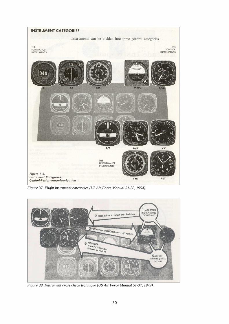
With many autopilot modes and pilots increased reliance on autopilots, these basic aerodynamic principles seem to be forgotten by airline pilots normally controlling the aircraft through the autopilot. Developments in Pilot Education and Training Instrument flying (“blind flying”) was first introduced by Jimmy Doolittle in USA in 1929. However, it was not until World War II that instrument flying became standard pilot proficiency. After the war instrument flying was continuously developed by improved instrumentation and pilot procedures. The concept of Attitude Flying was introduced (Fig. 36). The basic principle is that the pilot controls the airspeed by lowering or raising the nose attitude of the aircraft. He/she controls the heading by banking in the wanted direction of flight and thus turning to the required heading. These are the basic and intuitive piloting principles both in visual and instrument flight. In visual flight the pilot uses the natural horizon as reference, and in instrument flight he/she uses the attitude indicator (“artificial horizon”). This concept was further developed into categories of instruments; Control Instruments consisting of Attitude and Power Instruments, Performance Instruments and Navigation Instruments. The principle was simple and intuitive; the pilot controlled the attitude of the aircraft by reference to only two instruments and monitored the performance and navigation instruments for proper response (Fig. 37). A special pilot instrument cross check was developed (Fig. 38), where the main instruments were the Attitude and Power indicators (Control Instruments). Improper cross check technique could result in chasing the performance indicators prohibiting stabilized flight (Fig. 39). The student pilots were trained according to these principles and learned to scan the instruments in a certain scan pattern, where the Attitude Indicator was in the center and the most frequent scanned instrument. The faster this scan could be developed, the better situational awareness for the pilot. Today’s state-of-the-art instrument panel seems to have lost some of the benefits of the older panel (Fig. 40). The panel seems very clean and uncluttered and is certainly saving space (and money). It is quite sufficient during routine benign flight conditions within 15° of pitch and 30° of roll attitude, but not optimal during a dynamic unusual attitude (LOC) situation. And what is the standard instrument cross check for the state-of-the-art instrument panel (of the “glass cockpit”)?

29
Figure 36. The concept of attitude instrument flying (US Air Force AF Manual 51-38 1954).
30
Figure 37. Flight instrument categories (US Air Force Manual 51-38, 1954).
Figure 38. Instrument cross check technique (US Air Force Manual 51-37, 1979).

31
Figure 39. Factors influencing cross check technique (US Air Force Manual 51-37, 1979).
During basic and advanced flight training, both in visual and instrument flight, it was emphasised that the primary Flight Control Instruments were the Attitude Indicator and the RPM/Power instrument – Pitch controlled airspeed and Power controlled climb and descent according to: R/C = (T – D)V/W R/D = (D -T)V/W This knowledge was also the fundamental basis for controlling an aircraft during any emergency or upset flight condition:
• Maintain aircraft control (by use of attitude and power) (Aviate)
• Analyse the situation (Navigate) • Take proper action (Communicate)
Today’s pilots seem to forget this, possibly because authorities and manufacturers allow design and operational use of conflicting control laws and operational practice.

32
Figure 40. State-of- the- art PFD. Recommended Cross Check Technique? (Wikipedia 2013).
With reference to State-of-the-art (“all in one”) PFD’s, what is the recommended instrument scan pattern? The author has several hundred flight hours with similar types of display, but was not introduced to any recommended scan pattern. The general idea was that all the information is included on one display, “right in front of you”. However, several LOC accidents in recent years may indicate that the state-of-the-art PFD’s are not as efficient as thought of in the industry. These types of PFD’s are satisfactory only during benign flight conditions, but not during a dynamic or upset flight situation leading to an unusual attitude. In such flight conditions all flight parameters are changing and the human brain may be saturated by changing parameters and digits that need direct readings and interpretation. Fig. 41 shows a new Universal PFD with a computer generated picture of the outside world. These types of AI may give the pilot a better situational awareness in an unusual attitude. Even better would be a larger screen with analog round dials with pointers, including AOA indicator.

33
Figure 41. Universal Avionics PFD (Internet 2013).
Fig. 42 shows a similar PFD from Rockwell Collins. The airspeed, AOA, altitude and VSI are overlaid on the terrain picture. This PFD would help the pilots maintain their situational awareness even in unusual attitudes and high alpha flight conditions. Otherwise, the same comments as to Fig. 41. As an experienced flight and aerobatic instructor the author has seen the reactions of students with limited or no outside references. During such flight conditions the student pilot’s loose aircraft control very quickly. However, once visual reference to the outside terrain is regained, they may regain aircraft control within reasonable time. Therefore, future Primary Flight Displays should be based on a synthetic picture of the outside world with overlaid primary flight instruments, and where the AOA indicator should get a prominent display.

34
The human brain is analogue and there seem to be human factor indications that round analogue instruments may be easier and quicker to read/interpret than digital indications23. This may be important during dynamic flight situations. A reminder to this effect is that most people use wrist watches with round dials and pointers (analogue display) in lieu of watches with digits (digital display).
Figure 42. Rockwell Collins Proline Fusion (Internet 2013).
Figure 43. Enhanced Flight Vision System (Curt Lewis & Associates, Flight Safety Information, September 5, 2013). 23
Reference 8 and Fig. 21

35
Fig. 43 shows a modern Enhanced Flight Vision System (EFVS) on a head Up Display (HUD) for use below 100 ft during landing. In line with previous arguments this author considers that the display may be more human factor centered by substituting the digital information for airspeed, groundspeed, radio altitude and vertical speed with “pointers with dots” as shown in Fig. 46 (based on human factor research, ref. 4), or variants of dial and pointer display.
Figure 44. Pilatus PC-12 PFD (Rein Inge Hoff, September 2013).
Figure 44 show the PFD of the Pilatus PC-12. Based on the author’s previous arguments this display could have been improved by using the whole screen area for the attitude display, with overlaid round dials for airspeed/AOA and altitude, etc, similar to the TRQ, ITT and NG indicators on the left. These engine instruments should not be part of the PFD and should not occupy valuable space on the PFD. Figure 45 shows a proposed flight display in reference 20, based on the computer state-of-the-art 20 years ago. With the advancement in computer and avionics technologies during the latest decades, it is somewhat strange that these technologies have not materialized in new advanced cockpit displays in modern aircraft.

36
Figure 45. The Big Picture (Coombs 1990)24. Cockpit Displays – Test and Evaluation Reference 21 addresses test and evaluation of cockpit displays:
“There have been a number of papers and articles written about operational difficulties with modern display and other cockpit systems. As we see it, the problem has been a series of discontinuities between the users and the designers, between the designers and the testers, and between the users and the testers. As a result of the first discontinuity, between users and designers, inadequate design requirements are established. This is particularly unfortunate as systems can be (and are being) designed with greater and greater capabilities in terms of automatic flight and guidance and flight control. Without adequate requirements, it is hardly surprising that there are problems encountered in operational use.
24
Reference 20

37
The second discontinuity, between designers and testers, reduces the opportunities for feedback to the designer. In fact, with today’s economic setting, many systems are practically committed to production by the time they reach flight test. Only if there are very serious problems, will these systems be corrected. The third discontinuity, between users and testers, results in inadequate test criteria. As a result of this discontinuity, we are left with highly subjective criteria which vary from tester to tester. Or we have inappropriate criteria.” “ The display design must consider why the pilot needs the data and what the pilot is expected to do with the data. According to Singleton, several questions must be answered during development of a display:
� Does the pilot’s need justify the display? � What data does the pilot need that has not been provided? � Can the average pilot obtain what is required easily? � Does the display conform to the real world?
To other cockpit displays? With previous pilot habits and skills? With required decisions and actions?”
Research on Primary Flight Displays and inclusion of AOA Indicator
The author has not seen any research papers related to the state-of-the-art PFD’s used throughout the industry or presentations during SETP symposiums. Reference 4 describes the results of a research program related to readability of different types of airspeed and altitude displays on HUD’s.
Figure 46. Different types of Airspeed and Altitude displays with Mean Subjective Ratings25.
25
Reference 4

38
References 11 and 12 describe the results of a research project at National Research Council (NRC) in Canada, testing out the efficiency of some types of attitude references in recovering from unusual attitudes (UA).
Figure 47. Arc-segmented attitude reference (ASAR). Figure 48. Moving horizon pitch ladder display.
Figure 49. Asymmetric attitude reference display.
Figure 50. Reaction time. Figure 51. Correct initial control input.
It is not suggested that these types of displays are the solution to LOC accidents. However, these research studies indicate that in an unusual attitude flight situation the shape and format of primary attitude displays play a significant role, and may help pilots quickly regain control of an upset aircraft.

39
The author has not seen any research data supporting the human factor benefits of the state-of-the-art PFD’s of today. The display types are 30 years old and it is time to develop new PFD based on human factor research and technological advancements. The author suggest that SETP should get more involved in human factor focused development, simulator and flight experiment, and flight testing of new types of PFD’s.
Conclusions
Several recent LOC accidents indicate that the human factor related aspects of primary flight displays, lack of AOA displays, flight control and inceptor design, and pilot education and training, play a significant role in the pilot’s handling of an aircraft. It is recommended that the industry initiate more human factor based research within these areas26. SETP should get more involved in human factor focused development, simulator and flight experiment, and flight testing of new types of PFD’s. 26
One such research program is being performed by Embry-Riddle Robertson Safety Institute http://prescott.erau.edu/rsi/projects/AoApage/index.html

40
References
1. USAF Test Pilot School, Stability and Control Handbook, FTC-TIH-68-1002 1968.
2. NASA Technical Memorandum 74097, Aerodynamic Characteristics of Airplanes at High Angles of Attack. Joseph R. Chambers and Sue B. Grafton, NASA Langley Research Centre 1977.
3. Svimonoff, C. The Air Force Integrated Flight Instrument Panel. WADC TR 58-431,
October 1958.
4. Ercoline, W and Gillingham, K. Effect of Variations in Head-Up Display Airspeed and Altitude Representations on Orientation Recognition. Proceedings of the Human Factors Society 34th Annual Meeting 1990.
5. Reising, M. J., Butterbaugh, L. C., Liggett, K. K. Preliminary Assessment of primary
Flight Display Symbology for Electro-optic Head-Down Displays, June 1991.
6. Human Factors Team Report on the Interfaces between Flight Crews and Modern Flight Deck Systems. FAA 1996.
7. Lovesay, E. J. The Instrument Explosion – a Study of Aircraft Cockpit Instruments.
Applied Ergonomics 1997.
8. Lande, K. Standardization of Flight Decks - Operational Aspects. Soekkha, H (Ed). Aviation Safety - Human Factors - System Engineering - Flight Operations - Economics - Strategies - Management, pp. 189-201. Proceedings of the International Aviation Safety Conference 1997 (IASC-97). VSP BV 1997.
9. Harris, D. Head-down flight deck display design. Harris, D (Ed). Human Factors for Civil Flight Deck Design, pp. 69-102. Ashgate 2004.
10. Field, E. Handling qualities and their implications for flight deck design. Harris, D (Ed). Human Factors for Civil Flight Deck Design. pp. 157-181. Ashgate 2004.
11. Brown, A. P., Dillon, G. C. J., Erdos, R. Flight Manoeuvres and Spin Characteristics of the Harvard Mk 4: Application to Human Factors Flight Research. AIAA 2004-4815, 2004.
12. Leslie, T. NRC Canada Harvard Unusual Attitude Recovery Research Project. AB-FRL-2002-0045, June 2002.
13. AC 25-11A. Electronic Flight Deck Displays. FAA 2010.
14. Learmount, David. In Focus, Flight International. January 2012.
15. Dekker, S. The Field Guide to Understanding Human Error. Ashgate 2006.

41
16. Reason, J. Managing the Risks of Organizational Accidents. Ashgate 1997.
17. Bennett, S. Dr. The Air France 447 Accident – Organizationally and Socially Produced? RAeS, The Aerospace Professional, p. 20-21. October 2012.
18. Lande, K. Causes for Pilot Mistakes - Aircraft Controllability - Cockpit Design -
Flight Displays - Basic Pilot Training. SETP Flight Test Workshop, Salzburg November 2012.
19. Graham H. Richard, Col. USAF (Ret). Flying the SR-71 Blackbird, Zenith Press 2008.
20. Coombs L. F. E., The Aircraft Cockpit, from stick-and-string to fly-by-wire, Patrick Stephens 1990.
21. Newman Rickhard L. and Greeley Kevin W., Cockpit Displays: Test and Evaluation, Ashgate 2001.