AIRCRAFT CIRCULARS 17ATIOYAL AVISORY coI:MITTE … · · 2013-08-31AIRCRAFT CIRCULARS 17ATIOYAL...
12
AIRCRAFT CIRCULARS 17ATIOYAL AVISORY coI:MITTE FOR AEFOATJTICS No. 203 THE VICKERS-SU p :RI,:ARINE SCPA" (BRITISH) A Ii1itary Plying Boat Washington :a: 1933 https://ntrs.nasa.gov/search.jsp?R=19930090282 2018-05-30T23:12:26+00:00Z
Transcript of AIRCRAFT CIRCULARS 17ATIOYAL AVISORY coI:MITTE … · · 2013-08-31AIRCRAFT CIRCULARS 17ATIOYAL...

AIRCRAFT CIRCULARS
17ATIOYAL AVISORY coI:MITTE FOR AEFOATJTICS
No. 203
THE VICKERS-SUp:RI,:ARINE SCPA" (BRITISH)
A Ii1itary Plying Boat
Washington
:a: 1933
https://ntrs.nasa.gov/search.jsp?R=19930090282 2018-05-30T23:12:26+00:00Z

ITATIONAL ADVISORY COMMITTEE FOR AERONAUTICS
AIRCRAFT CIRCULAR NO. 203
THE VICKERS-SUPERMARIHE 11 SCAPA 11 (:BRITISH)*
A Military Flying Boat
The "Scapa" has been designed to be used for observa-tion, bombing, torpedo transport, and training and naviga-tional instruction. The character of the military load carried will, of course, depend upon which of these func-tions the flying boat is fulfilling, but the arrangement of. the crew's stations remains the same. In the extreme bows there is a special machine-gun mounting which can be re-moved and stowed farther aft, leaving the front cockpit free for mooring operations, etc. This cockpit has, in the extreme nose of the hull, a hinged watertight door which is used for bomb sighting.
AER0DYNAL'IC DESIGN
Quite remarkable care has been taken in the design of the "Scapa to reduce head resistance. The hull itself has very clean lines, and on it is mounted a wing struc-ture in which the number of parts has been reduced to a minimum. Apart from the slanting struts which carry the two Rolls-Royce Kestrel engines, there is but a single pair of iitorplane struts on each side. The engine na-cellos themselves are of streamline form (fig. 4), and by placing the water radiators at the rear end of the nacelle, the usual unsightly and drag-producing excrescences are avoided. Lateral stability on the water is insured by two wing-tip floats, also of low-drag form and mounted each on a single pair of struts.
A monoplane tail is carried on the rising stern por-tion of the hull, to which it is braced by two struts on each side. Above the stabilizer are mounted two vertical fins carrying horn-balanced rudders. The IjflhI area caused by the tail is not, therefore, large, and the rear guns have a wide field of fire.
"From Plight, April 26, 1934, Plight, February 27, 1936, and The.Aeroplane, February 26, 1936.

2 N.A.C.A. Aircraft Circular No . . .203
Between the forward .cockpit and the wings is the pi-, lots' compartment which, in the "Scapa", is provided . with a sliding roof and side windows. The navigator and engi-neer are housed aft of the pilot cabin, between it and the hull frame which carries the front lower wing spar, while slightly farther. aft, between the two spar frames, is the WIT operator's station. Behind the wings are the two rear gun positions which, as already.' mentioned, afford very good tail protection owing to the shape and location 0.1' the tail srfaces (fig. 5).
If the Scapa is being used for extended cruises, provision is made for sleeping accommodation., food and wa-ter stowage, cooking table, and other special equipment. Stowage is also arranged for a collapsible dingey, an en-gine ladder, an engine maintenance platform, and a spare propeller.
STRUCTURAL FEATURES
Light alloys, and stainless steel ai'e the chief struc-tural materials of the"Scapa". The stainless steel is used mainly for highly stressed fittings, and the light alloy for planking, frames, wing' spars, and wing ribs, Doped fabric is used for covering the wings and tail sur-faces.
Extensive tank tests on models resulted in a hull form which combines low air drag with clean running on the water and good. seaworthiness.
For some years it was customary for British flying boats to have flaring chines, with the underwater body showing a flat vee curving sharply from keel to chine in order to keep down spray when the seaplane was taxying and taking off. Modern tendency is toward flat sides and-near-ly straight-line vees in the hull bottom. The 'Scapa in this respect may be regarded as an intermediate type in that the curves of earlier seaplanes are retained, but have become very much flattened out. This is,' of cOu±s 'e, an ad-vantage from a manufacturing point of view, as it avoids a great deal of panel beating. If a sheet of material, metal in this case, is bent simply, it will be found that a straight edge can be laid along it in such a way as to make continuous contact. If, however, one tries to, bond the sheet in t'vo directions, it is found that this cannot be done except by working on the sheet in such, a way as to

N..C.A. Aircra't Circular No. ..Q3. 3
cause it to stretch in some places and. contract in others. It is this process'which'is known as panel . beating. Dif-ferently explained., one can:benda';heet- of metal around a c r linder but not around a barrel.
The sections of the."Scapa" hayc; been so chosen that panel beating is a'lmost . entirely..avoided, the.raain excep-tion being the region around:the:extremebows. Porthe rest, the sheet-metal covering of the"Scapa" hull is put on in fairly large panels (roughly, .4 ft.. 6 in. long by 20 in. wide) ,,so that the number of joints which have to be made watertight is reduced to a minimum.
In building the flscapaI hulls:, the keel is first se-cured on the stocks. The keel is built up to form an 1 section,',and consists of a.flat stri p cut to the contour which the keel is desired to have, stiffened at top and bottom by flanges. These consist of extruded T sections, the vertical limbs of the-T's being riveted to the edges of the keel web. . . . .
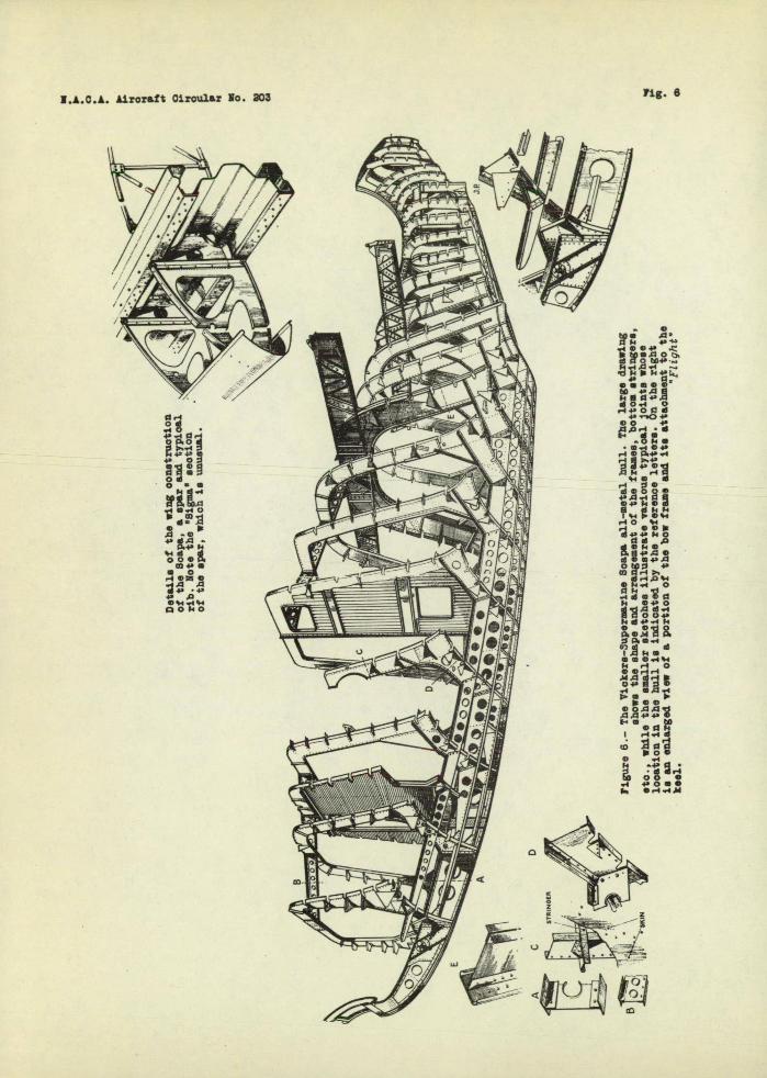
When the keel 'has boon finished, the frames are erect-ed on it in their proper positions and temporarily held in place, while some, of the fore-and-aft stringers are at-tached. The main stringers are, of two-general types: plain channel sections formed by bending .th'e sheet: itself to form the flanges, and. T sections in which. theedge farthest from the Dlanking is formed by two L-section strips , riveted through the web of the stringer. The stringer 'edge in con-tact with the 'planking is usually bent over to, lie flat against the planking being riveted to it.,.Apart from I-section stringers, use is also . -made of the .so-calledZ section, in which the two angles are riveted on.'in.oppo-site directions. The Z. section has the advantage that it leavQs the member very accessible for riveting. Interme-diate light stringers in the "Scapa" are of what one might call £ section. That is to say,..the edge in contact with the-hull planking is bent over at . right , angl .es for riveting, while the free-'edge is curled over to give extra stiffness. The stringers are attached to the'-frames by small gussets, flanged over to provide the necessary riv-eting area, as shown in figure 6.
Several types of frare arc used... The simplest is a: plain channel section, having outer and inner flanges formed by simply bending over the edges of the fresh nate-rial itself . . Others have the flanges'formed by.riveted-on angles. The spar frames are of slightly more substan-

4 LA.C.A. Aircraft Circular 1o. 203
tial côntruction, having two angles riveted on at the planhing, two at the free edge, the latter being further reinforced by a cap-strip having its edges curled over for stiffness.
These spar frames have their webs extended upward to form the webs of the main wing spars, so that the roots of the lower wing are actually integral with -the hull. The details will be understood from a reference to figures 6, 7, and 8. It should be noted that the stringers of the "Scapa" are continuous from bow to stern, and that they are notched into the frames, as shown in the sketches. In another form of hull construction, the frames are contin-uous, and the stringers interrupted at the frames, being attached to them by gussets. At present it does not seem decided which form of construction is the most satisfac-tory.
When the frames and most of the stringers are in place on the hull, the planking begins. The chine is formed by an L-section strip. This is temporarily held in place by screws to the frames, small pieces of metal of the same thickness as the, actual planking being inserted o leave the necessary gar, The sheets of the planking.
are then uoffered up" to the job, marked out, cut to size, and fitted. when a perfect fit has been attained, the piece of sheet is taken to the anodizing plant for treat-rient, and when that is finished it is brought back to the job, inserted in its proper place and finally secured by rivets to frames, stringers, and chine.. Whre the plates overlap, the edge of the outer is "stepped over the edge of the inner before they are riveted together,' so that ex-cept at the seams the two adjacent plates-are perfectly in line. Marine glue is brushed on the edges before the plates are riveted together to insure watertightness.
At the two steps a transverse covering strip is used to insure a:watertight joint. This strip is of Z-section, and conforms to the transverse shape of the hull at the steps. An interior view of the hull fore and aft is given in figures 9 and 10.
In the wing construction of the "Scapa" fairly normal practice is followed'. An exception is ,, however, found, in Ihe wing spars, which are of very unusual section. Per-haps this section may be described as a Z-section, resem-bling roughly, the Greek capital letter sigma. It congists

T.A.C.A. Aircraft Circular No. 203 5
of a single corrugated web to which are riveted the two flanges.
Several advantages are gained by this very ingenious sDar construction. As the spar is "open" from both sides, the riveting, holding-up, etc., becomes very easy. The sections are simple to form on rolling mill and drawbench, the web by pressing, and finally the attachment of ribs and drag bracing can be very simply carried out.
It is obvious that the type of spar web used is not by itself able to resist any very considerable vertical loads without collapsing. On the side of the spar where the spar flanges are attached to the web, the necessary strength in a vertical direction is obtained by the angle strips used to attach and reinforce the ribs. On the "open side, similar stiffnixg is, introduced, and where local loads demand stiffeners in between rib locations, these take the form of simple channel section struts, riveted to the spar flange.
The wing ribs are mostly of duralumin tube construc-tion, but some of the heavier ribs, such as those which form compression ribs, or which carry bomb loads, tanks, etc., have channel section flanges with chahel section ties.
The wings are of equal-span biplane form, and the ai-lerons, fitted to all four wings, have Frise balances. The one-piece elevator has a hor.n balance at each end, ar-ranged in a somewhat unusual way. Instead of the horn bal-ance of aprcximatel.y triangular shape, those. of the fl .Scapa T elevator are of rectangular form, and are inset in the tail surfaces, not at the extreme end but a. short way from the tips. The. trailing edge,of the ele .ator has been cut away at an angle, probably in order to render the in- set balances more effective.
ENGINE INSTALLATION
Two objects were achieved by placing the. Kest rel en-gines mrnediately under the upper wing in the 11Scapa11 The position should give lowai.r 4rag, and at the same time the propellers are kept well clear of spray. The ex-haust. tail pipes a'e pointed outward so as to keep the hot exhaust gases from striking the radiators which, as previ-

6 M.A.C.A. Aircraft Circular To. 203
ously mentioned, are placed at the tail ends of the na-celles, under the trailing edge of the top wing.
Two gasoline tanks arc housed in the top center sec-tion. Each tank has a capacity of 230 gallons, and supply to the cninos is normally by direct gravity food from the tanks. Pumps are, however, provid0 to insure an adequate supply of fuel at abnormal attitudes (such as very stoop climb) when the tanks are nearly empty. Should the pumps. fail, the fuel is bypassed and the gravity head i' suffi-cient for normal attitudes. Oil is carried. in two tanks which form the loading edge of the top cantor section and incorporate oil coolers.
Special attention has been given to ease of mainte-nance, and although the high placing of the engines has rendered them slightly inaccessible, the use of enf;ine ladders and platforms facilitates the work, while large manholes enable the accessories at the back of the engines to be reached.
For launching the "Scapa" from a slipway or from the beach, and for bringing it ashore again under its own power, a launching trolley is provided. This consists of two sop-. arate units, cach . comrising a wheel and three struts. Each unit is attached at throopoins by quick-release pins: two points on the hull and one point on the lower wing. A tail trolley is also supplied.
For emergency, provision has been made for carrying a spare engine on the lower center section. The absence of central struts leaves an open space on the center line of the seaplane, in the angle between the center bay wing bracing wires and internal supports are provided so that a spare engine can, if necessary, be carried here.
DIME T S 10 IT S
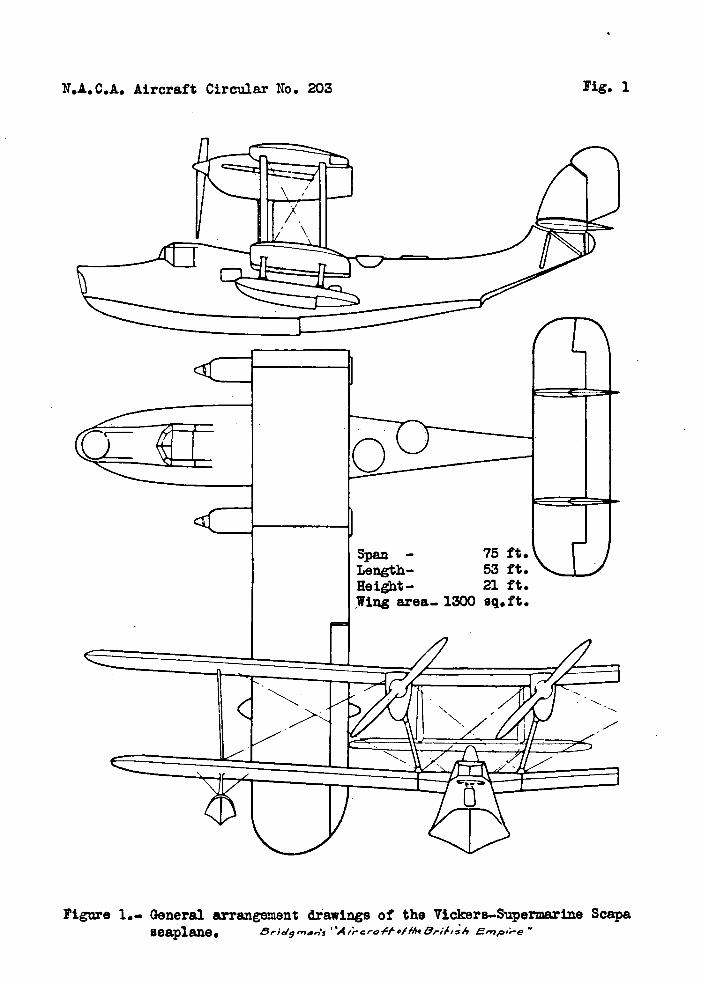
Span
75 ft. 22.85 m
Length, over-all
53 ft. 16.2 m
Height (on beaching chassis)
21 ft. 6.4 m
Wing area 1,300 sq.ft. 121.0 m2
N.L.C.A. Aircraft Circular No. 203
Fig. 1
Figure 1... General arrangement diawings of the Vickers—Sipermarine Scapa seaplane. 8,-IS9 ma.,s 4,rcrtofThe8pd,4 Empi.-e'

LA. C.A. Aircraft Circular No. 203
Figs. 2,3,4
I
Figures 2,3.- Three-quarter views of the Supermarine Scapa observation seaplane. (2 Rolls-Royce Kestrel engines). Paris Office NA.C.A.
Figure 4.- View of the Scapa engine nacelle, which has been placed on its side in order to show the
inspection doors in the floor by which engineers reach the engines. The nacelle I. of all-metal eonstraetion. "Flight"

•L
-I
4 i11Ij
/
a
N.A.C.A. Aircraft Circular No. 203
!
Ir. -i I
_w 7 Dfl
MOM
LAAM
La
!fl jN '=
i
ii WWAI
IN
!IiJI I .'iip-
I.A.O.A. Aircraft Otroul&r 10. 203Fig. 6
0 A.
4. -I
•
0
140 044 P.4 P C -I
C0
0 P414 • 44
P4.
0
dog
44
000

0
43
1-443
S
I
LI
r-1
U
P,S
43 P2 HIJ
I, a)
N
.4) 43 0 o
I j. o
Go
1
N.A.C.A. Aircraft Circular No. 203
Figs. 7,8,9,10


![[XLS]worldwideaerospace.comworldwideaerospace.com/Worldwide Aerospace Inv1.xlsx · Web view95-XXX-6D1-19552 9603A 704A46860001 PANEL, FAILURE AVISORY 960453-1 RESERVOIR ASSY HYDRAULIC](https://static.fdocuments.in/doc/165x107/5ac5f0027f8b9aa0518e42b4/xls-aerospace-inv1xlsxweb-view95-xxx-6d1-19552-9603a-704a46860001-panel-failure.jpg)