Aircraft Accident Report 1/2013, Civil Aviation Department ... Accident Report.pdf · 1 FACTUAL...
92
AIRCRAFT ACCIDENT REPORT 1/2013 ACCIDENT INVESTIGATION DIVISION Civil Aviation Department The Government of Hong Kong Special Administrative Region Report on the accident to Eurocopter AS332 L2 Super Puma Registration B-HRN operated by the Government Flying Service of Hong Kong at Shing Mun Reservoir on 27 December 2010 Hong Kong April 2013
Transcript of Aircraft Accident Report 1/2013, Civil Aviation Department ... Accident Report.pdf · 1 FACTUAL...
AIRCRAFT ACCIDENT REPORT 1/2013
ACCIDENT INVESTIGATION DIVISION
Civil Aviation Department The Government of
Hong Kong Special Administrative Region
Report on the accident to Eurocopter AS332 L2 Super Puma Registration B-HRN operated
by the Government Flying Service of Hong Kong at Shing Mun Reservoir on 27 December 2010
Hong Kong April 2013
In accordance with Annex 13 to the ICAO Convention on International Civil Aviation and the
Hong Kong Civil Aviation (Investigation of Accidents) Regulations, the sole objective of this
investigation is the prevention of aircraft accidents. It is not the purpose of this activity to
apportion blame or liability.
i
iHHUH7 i!ll:l!<i!ll:~
!"R.M:.!ll!: CiVIL AVIATION DEPARTMENT
The Government of the Hong Kong Speclai .A.dministrative Region
~ it! ::!\: ~ ill ~ jit ~ llfiH~ ~ JIUlf! !m Hit EHit J#f; ~, im Civil Aviation Department Headquarters 1 Tung Fai Road, Hong Kong International Airport, Lantau, Hong Kong
The Honourable C Y Leung, GBM, GBS, JP The ChiefExecutive
Hong Kong Special Administrative Region People's Republic of China
Dear Sir,
~~ Tel: (852) 2910 6363
IIJ)l::~J:j; Fax: (852) 2501 0640
~~11ii\~ Our ref:
*lil:l~~ Your ref:
16 April 2013
In accordance with Regulation 1 0( 6) of the Hong Kong Civil Aviation (Investigation of Accidents) Regulations, I have the honour to submit the report by Mr. LEUNG Man-fat, an Inspector of Accidents, on the circumstances of the accident to a Eurocopter AS332 L2 Super Puma helicopter, registration B-HRN at Shing Mun Reservoir on 27 December 2010.
Yours faithfully,
(Norman S M LO) Director-General of Civil Aviation
~~MR~·~~$&~M-~M~~~·S$~ Committed to a Safe, Efficient and Sustainable Air Transport System
MFLEUNG
Text Box
ii
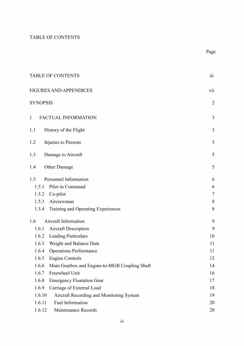
TABLE OF CONTENTS
Page
TABLE OF CONTENTS iii
FIGURES AND APPENDICES vii
SYNOPSIS 2
1 FACTUAL INFORMATION 3
1.1 History of the Flight 3
1.2 Injuries to Persons 5
1.3 Damage to Aircraft 5
1.4 Other Damage 5
1.5 Personnel Information 6
1.5.1 Pilot in Command 6
1.5.2 Co-pilot 7
1.5.3 Aircrewman 8
1.5.4 Training and Operating Experiences 8
1.6 Aircraft Information 9
1.6.1 Aircraft Description 9
1.6.2 Leading Particulars 10
1.6.3 Weight and Balance Data 11
1.6.4 Operations Performance 11
1.6.5 Engine Controls 12
1.6.6 Main Gearbox and Engine-to-MGB Coupling Shaft 14
1.6.7 Freewheel Unit 16
1.6.8 Emergency Floatation Gear 17
1.6.9 Carriage of External Load 18
1.6.10 Aircraft Recording and Monitoring System 19
1.6.11 Fuel Information 20
1.6.12 Maintenance Records 20
iii
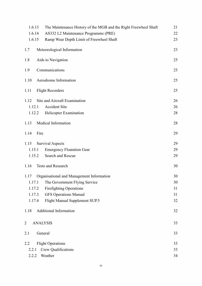
1.6.13 The Maintenance History of the MGB and the Right Freewheel Shaft 21
1.6.14 AS332 L2 Maintenance Programme (PRE) 22
1.6.15 Ramp Wear Depth Limit of Freewheel Shaft 23
1.7 Meteorological Information 23
1.8 Aids to Navigation 25
1.9 Communications 25
1.10 Aerodrome Information 25
1.11 Flight Recorders 25
1.12 Site and Aircraft Examination 26
1.12.1 Accident Site 26
1.12.2 Helicopter Examination 28
1.13 Medical Information 28
1.14 Fire 29
1.15 Survival Aspects 29
1.15.1 Emergency Floatation Gear 29
1.15.2 Search and Rescue 29
1.16 Tests and Research 30
1.17 Organisational and Management Information 30
1.17.1 The Government Flying Service 30
1.17.2 Firefighting Operations 31
1.17.3 GFS Operations Manual 31
1.17.4 Flight Manual Supplement SUP.5 32
1.18 Additional Information 32
2 ANALYSIS 33
2.1 General 33
2.2 Flight Operations 33
2.2.1 Crew Qualifications 33
2.2.2 Weather 34
iv

2.2.3 Weight and Balance 35
2.2.4 Operational Procedures and Ditching 37
2.2.5 Helicopter Performance 40
2.3 Survivability 40
2.4 Engineering 41
2.4.1 Helicopter General 41
2.4.2 The No.2 Engine-to-MGB Coupling Shaft and the Free Turbine Overspeed Safety
System 42
2.4.3 DECU 42
2.4.4 Flight Data 43
2.4.5 Voice Recording of the Cockpit Ambient 43
2.4.6 EuroARMS 44
2.5 Examination of the Main Gearbox 44
2.6 Examination of the Right Freewheel Unit 45
2.6.1 Freewheel Shaft 45
2.6.2 Rollers and Cage 47
2.7 Analysis of Oil Samples from the Freewheel Unit 51
2.8 Growth of Ramp Wear 52
2.9 Deformation of MGB under Flight Loads 53
2.10 Effect of MGB Casing Deformation on Freewheel Rollers 55
2.11 Effect of Power Level on Position of Freewheel Roller on Ramp 56
2.12 Evolution of Ramp Wear 57
2.12.1 Ramp Wear Growth and Flight Loads 57
2.12.2 Wear on Ramp #4 and #10 58
2.12.3 Wear on Ramp #1 and #7 60
2.12.4 MGB Deformation and the Ramp Wear Limits 61
2.13 Actions Already Taken by Eurocopter 63
2.13.1 Freewheel Shaft Ramp Wear Limit 63
2.13.2 Freewheel Shaft and Ball Bearing Replacement during MGB Overhaul 63
2.13.3 Redesign of Freewheel Shaft 64
2.13.4 MGB Modification 64
v
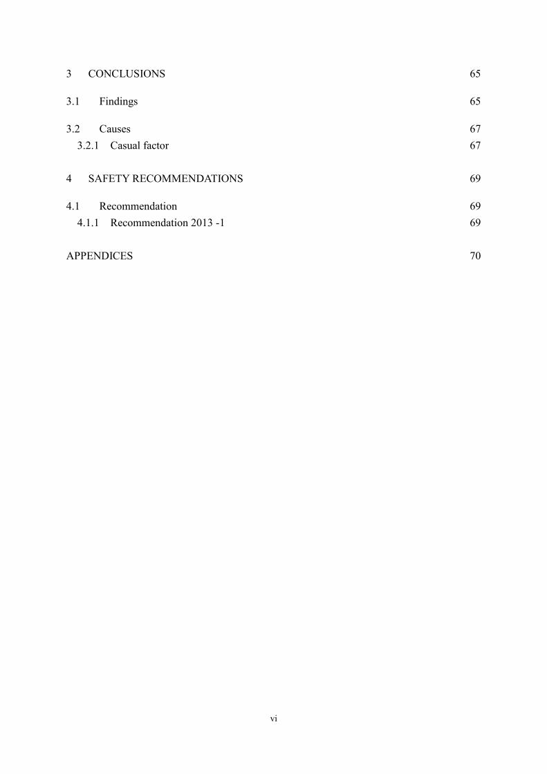
3 CONCLUSIONS 65
3.1 Findings 65
3.2 Causes 67
3.2.1 Casual factor 67
4 SAFETY RECOMMENDATIONS 69
4.1 Recommendation 69
4.1.1 Recommendation 2013 -1 69
APPENDICES 70
vi
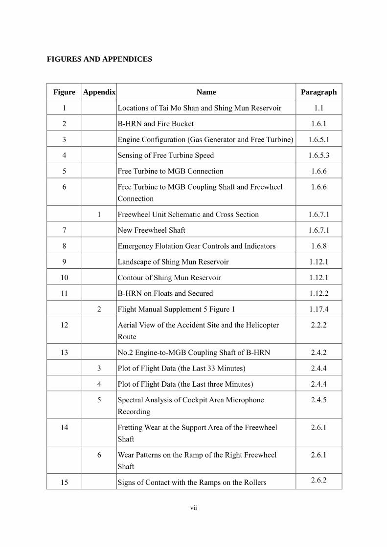
FIGURES AND APPENDICES
Figure Appendix Name Paragraph
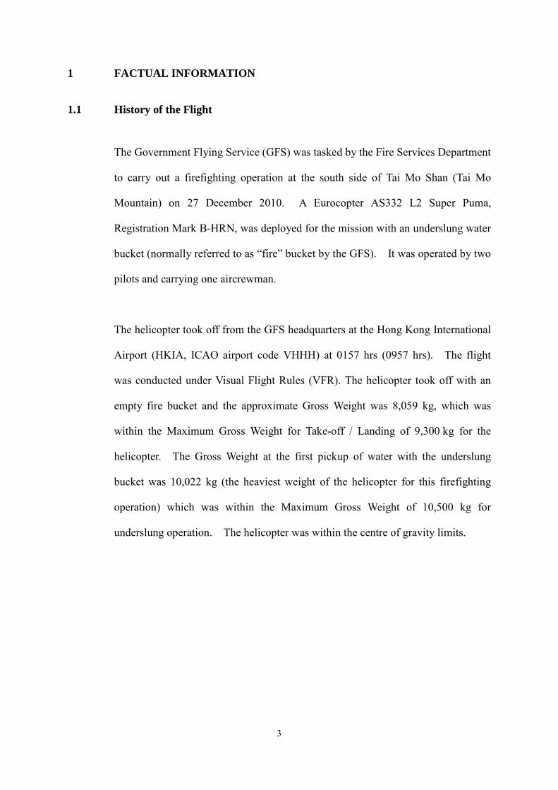
1 Locations of Tai Mo Shan and Shing Mun Reservoir 1.1
2 B-HRN and Fire Bucket 1.6.1
3 Engine Configuration (Gas Generator and Free Turbine) 1.6.5.1
4 Sensing of Free Turbine Speed 1.6.5.3
5 Free Turbine to MGB Connection 1.6.6
6 Free Turbine to MGB Coupling Shaft and Freewheel Connection
1.6.6
1 Freewheel Unit Schematic and Cross Section 1.6.7.1
7 New Freewheel Shaft 1.6.7.1
8 Emergency Flotation Gear Controls and Indicators 1.6.8
9 Landscape of Shing Mun Reservoir 1.12.1
10 Contour of Shing Mun Reservoir 1.12.1
11 B-HRN on Floats and Secured 1.12.2
2 Flight Manual Supplement 5 Figure 1 1.17.4
12 Aerial View of the Accident Site and the Helicopter Route
2.2.2
13 No.2 Engine-to-MGB Coupling Shaft of B-HRN 2.4.2
3 Plot of Flight Data (the Last 33 Minutes) 2.4.4
4 Plot of Flight Data (the Last three Minutes) 2.4.4
5 Spectral Analysis of Cockpit Area Microphone Recording
2.4.5
14 Fretting Wear at the Support Area of the Freewheel Shaft
2.6.1
6 Wear Patterns on the Ramp of the Right Freewheel Shaft
2.6.1
15 Signs of Contact with the Ramps on the Rollers 2.6.2
vii
16 Wear on the Ends of the Rollers 2.6.2
17 Upper and Lower Faces of Cage 2.6.2
18 Fretting Wear on the Cage at Areas in Contact with Rollers
2.6.2
19 Comparison of Wear on Cage Recess Facing Ramp #1 2.6.2
20 Comparison of Wear on Cage Recess Facing Ramp #3 2.6.2
21 MGB Casing Deformation under Flight Loads (Distortion X 200)
2.9
22 Analysis of Loads on Rollers with Finite Element Model
2.10
23 Roller Positions on Ramp Corresponding to Levels of Power
2.11
24 Micro-displacement of Ramp Rollers and Evolution of Wear
2.12.1
25 Wear Analysis on Ramp #4 and #10 2.12.2
26 Ramp #7 and Spigot 2.12.3
27 Wear Analysis on Ramp #1 2.12.3
viii
GLOSSARY OF ABBREVIATIONS
ADD Acceptable deferred defect
ADELT Automatic Deployable Emergency Locator Transmitter
APS Aircraft Prepared for Service
ATC Air Traffic Control
BEA Bureau d’Enquetes et d’Analyses pour la Securite de l’Aviation Civile
CAD Civil Aviation Department
CVR Cockpit Voice Recorder
DECU Digital engine control unit
EASA European Aviation Safety Agency
EC Eurocopter
EUROCAE European Organisation for Civil Aviation Electronics
FDR Flight Data Recorder
GPS Global Positioning System
HI High
HKIA Hong Kong International Airport
HKO Hong Kong Observatory
HKSARG Hong Kong Special Administrative Region Government
HMU Hydro-mechanical control unit
hPa Hectopascals (unit measurement for atmospheric pressure)
hrs Hours
HUMS Health and Usage Monitoring System
IAS Indicated Airspeed
ICAO International Civil Aviation Organisation
IFR Instrument Flight Rules
IGB Intermediate gearbox
kg kilograms
ix
km kilometres
kt knots
LDP Landing decision point
LR Letter to Repair Stations
MEL Minimum equipment list
MGB Main gearbox
MRV Repair Manual
NF Engine free turbine rotational speed
NG Engine gas generator rotational speed
NL Speed of the free turbine (MGB entrance)
NMD Navigation and Mission Display
NR Main rotor speed
ºC Degrees Celsius
OCF Oil cooler fan
OEI One engine inoperative
PF Pilot flying
PNF Pilot not flying
PRE AS332 L2 Maintenance Programme
PWR Power
QNH Corrected mean sea level atmospheric pressure
SE Single engine
SLL Service life limit
SSCVFDR Solid State Cockpit Voice and Flight Data Recorder
TBO Time between overhaul
TDP Take-off decision point
TGB Tail gearbox
TSN Time since new
x
UMS Usage Monitoring System
UTC Co-ordinated Universal Time
VFR Visual Flight Rules
xi
ACCIDENT INVESTIGATION DIVISION
CIVIL AVIATION DEPARTMENT
Aircraft Accident Report 1/2013
Registered Owner: The Government of the Hong Kong Special
Administrative Region
Operator: The Government Flying Service
Aircraft Type: Eurocopter AS332 L2 Super Puma
Nationality: Hong Kong, China
Registration: B-HRN
Place of Accident: Shing Mun Reservoir located at the area between Tsuen Wan
and Sha Tin in the New Territories
Latitude:
Longitude:
22º 23.01' N
114º 08.77' E
Date and Time: 27 December 2010 at 0237 hrs UTC (1037 hrs Hong Kong local
time)
All times in this report are in UTC with Hong Kong local time
in parenthesis.
1
SYNOPSIS
The Accident Investigation Division of the Civil Aviation Department (CAD) was notified of
the accident by the duty Air Traffic Control supervisor at the Hong Kong International
Airport (HKIA) at 0247 hrs (1047 hrs) on 27 December 2010, and the investigation
commenced immediately after the notification. In accordance with the established
international practices the Bureau d’Enquetes et d’Analyses Pour la Securité de l’Aviation
Civile (BEA), representing the State of Manufacture of the helicopter, was informed of the
accident. The BEA appointed an Accredited Representative to lead a team of investigators
from Eurocopter (the helicopter manufacturer) and Turbomeca (the engine manufacturer).
The accident occurred whilst the Eurocopter AS332 L2 Super Puma helicopter operated by
the Government Flying Service (GFS) was carrying out a firefighting operation at the south
side of Tai Mo Shan on 27 December 2010. The helicopter was operated by two pilots and
carrying one aircrewman. After the sixth water pickup from the nearby Shing Mun
Reservoir, and whilst the helicopter was rotating to gain forward speed at 129 ft above the
water surface, the No.2 engine gas generator rotation speed (NG) wound down due to the
functioning of the automatic overspeed protection system. The helicopter then ditched in a
controlled manner into the reservoir, and was then kept afloat by the four emergency floats.
There was no injury to the three crew members on board or other persons on ground.
An extensive investigation of the main gearbox (MGB) and the right freewheel unit identified
that the automatic shutdown of No.2 engine was due to free turbine overspeed as the result of
a slippage of the right freewheel shaft in the MGB.
One safety recommendation has been issued by this report.
2
1 FACTUAL INFORMATION
1.1 History of the Flight
The Government Flying Service (GFS) was tasked by the Fire Services Department
to carry out a firefighting operation at the south side of Tai Mo Shan (Tai Mo
Mountain) on 27 December 2010. A Eurocopter AS332 L2 Super Puma,
Registration Mark B-HRN, was deployed for the mission with an underslung water
bucket (normally referred to as “fire” bucket by the GFS). It was operated by two
pilots and carrying one aircrewman.
The helicopter took off from the GFS headquarters at the Hong Kong International
Airport (HKIA, ICAO airport code VHHH) at 0157 hrs (0957 hrs). The flight
was conducted under Visual Flight Rules (VFR). The helicopter took off with an
empty fire bucket and the approximate Gross Weight was 8,059 kg, which was
within the Maximum Gross Weight for Take-off / Landing of 9,300 kg for the
helicopter. The Gross Weight at the first pickup of water with the underslung
bucket was 10,022 kg (the heaviest weight of the helicopter for this firefighting
operation) which was within the Maximum Gross Weight of 10,500 kg for
underslung operation. The helicopter was within the centre of gravity limits.
3
Figure 1 Locations of Tai Mo Shan and Shing Mun Reservoir
At 0210 hrs (1010 hrs), the helicopter arrived at the scene of the hill fire at Tai Mo
Shan and the pilot selected the adjacent Shing Mun Reservoir as the source of
water pickup. After the sixth water pickup with the bucket filled and just lifted
clear of the water surface, and whilst the helicopter was rotating to gain forward
speed at 129 ft above the water surface, the pilot noticed that the helicopter
suddenly yawed, and the crew members heard an engine winding down sound.
The flight crew noted warning lights “ALARM”, “PWR 2” and “OEI HI”
displayed on the instrument panel. In addition, the captain noticed that the No.2
engine gas generator rotation speed (NG) was winding down and passing through
30% on the No.2 engine NG gauge. About one second later, No.2 engine shut
4
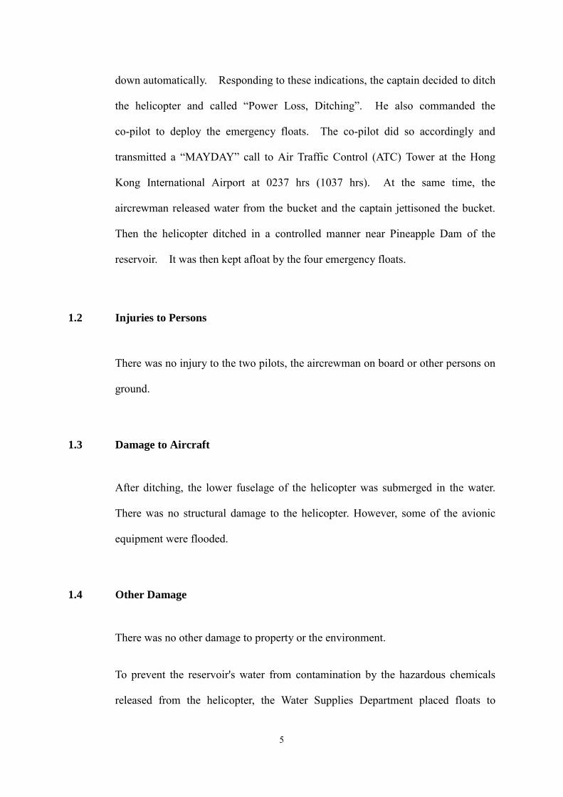
down automatically. Responding to these indications, the captain decided to ditch
the helicopter and called “Power Loss, Ditching”. He also commanded the
co-pilot to deploy the emergency floats. The co-pilot did so accordingly and
transmitted a “MAYDAY” call to Air Traffic Control (ATC) Tower at the Hong
Kong International Airport at 0237 hrs (1037 hrs). At the same time, the
aircrewman released water from the bucket and the captain jettisoned the bucket.
Then the helicopter ditched in a controlled manner near Pineapple Dam of the
reservoir. It was then kept afloat by the four emergency floats.
1.2 Injuries to Persons
There was no injury to the two pilots, the aircrewman on board or other persons on
ground.
1.3 Damage to Aircraft
After ditching, the lower fuselage of the helicopter was submerged in the water.
There was no structural damage to the helicopter. However, some of the avionic
equipment were flooded.
1.4 Other Damage
There was no other damage to property or the environment.
To prevent the reservoir's water from contamination by the hazardous chemicals
released from the helicopter, the Water Supplies Department placed floats to
5

cordon off the helicopter and guard against any potential fuel and oil spill. They
also took samples of the water for testing and confirmed that there were no signs of
contamination.
1.5 Personnel Information
1.5.1 Pilot in Command
Pilot: Male, aged 33 years
Licences: Air Transport Pilot’s Licence (Helicopter) Issued on 23 January 2007. Valid until 22 January 2017
Aircraft ratings: Eurocopter AS332 L2 Super Puma; Eurocopter EC155
Aircraft Rating on Type Certificate of Test:
25 October 2010. Valid
Proficiency Check on type: 25 October 2010. Valid
Line/Role Check on type: 27 October 2010. Valid
Medical Certificate: Class 1, renewed 20 Oct 2010, Valid to 31 October 2011 No Limitations
Flying Experience: (hours)
Total helicopter: Total on type: Last 90 days: Last 28 Days: Total for the day:
3,373 1,918
71 36 0.5
Previous rest period: 16 hours 50 minutes
6
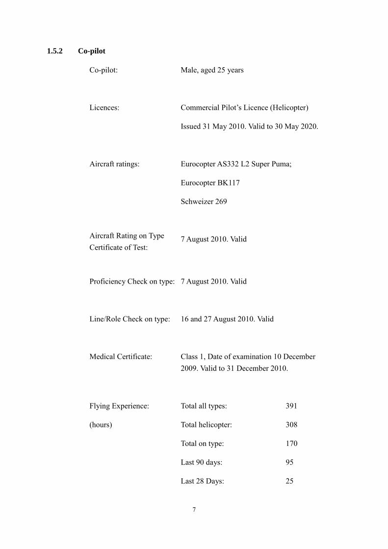
1.5.2 Co-pilot
Co-pilot: Male, aged 25 years
Licences: Commercial Pilot’s Licence (Helicopter)
Issued 31 May 2010. Valid to 30 May 2020.
Aircraft ratings: Eurocopter AS332 L2 Super Puma;
Eurocopter BK117
Schweizer 269
Aircraft Rating on Type 7 August 2010. Valid Certificate of Test:
Proficiency Check on type: 7 August 2010. Valid
Line/Role Check on type: 16 and 27 August 2010. Valid
Medical Certificate: Class 1, Date of examination 10 December 2009. Valid to 31 December 2010.
Flying Experience: Total all types: 391
(hours) Total helicopter: 308
Total on type: 170
Last 90 days: 95
Last 28 Days: 25
7
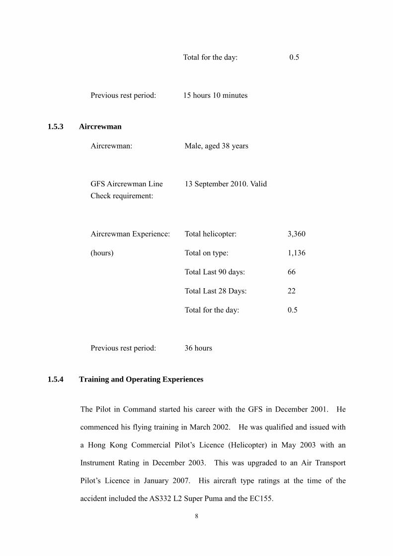
Total for the day: 0.5
Previous rest period: 15 hours 10 minutes
1.5.3 Aircrewman
Aircrewman: Male, aged 38 years
GFS Aircrewman Line 13 September 2010. Valid Check requirement:
Aircrewman Experience: Total helicopter: 3,360
(hours) Total on type: 1,136
Total Last 90 days: 66
Total Last 28 Days: 22
Total for the day: 0.5
Previous rest period: 36 hours
1.5.4 Training and Operating Experiences
The Pilot in Command started his career with the GFS in December 2001. He
commenced his flying training in March 2002. He was qualified and issued with
a Hong Kong Commercial Pilot’s Licence (Helicopter) in May 2003 with an
Instrument Rating in December 2003. This was upgraded to an Air Transport
Pilot’s Licence in January 2007. His aircraft type ratings at the time of the
accident included the AS332 L2 Super Puma and the EC155.
8
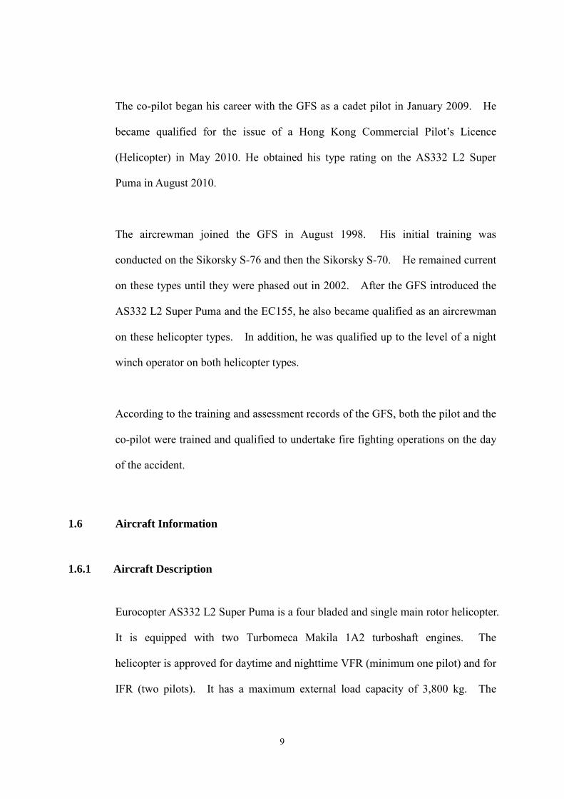
The co-pilot began his career with the GFS as a cadet pilot in January 2009. He
became qualified for the issue of a Hong Kong Commercial Pilot’s Licence
(Helicopter) in May 2010. He obtained his type rating on the AS332 L2 Super
Puma in August 2010.
The aircrewman joined the GFS in August 1998. His initial training was
conducted on the Sikorsky S-76 and then the Sikorsky S-70. He remained current
on these types until they were phased out in 2002. After the GFS introduced the
AS332 L2 Super Puma and the EC155, he also became qualified as an aircrewman
on these helicopter types. In addition, he was qualified up to the level of a night
winch operator on both helicopter types.
According to the training and assessment records of the GFS, both the pilot and the
co-pilot were trained and qualified to undertake fire fighting operations on the day
of the accident.
1.6 Aircraft Information
1.6.1 Aircraft Description
Eurocopter AS332 L2 Super Puma is a four bladed and single main rotor helicopter.
It is equipped with two Turbomeca Makila 1A2 turboshaft engines. The
helicopter is approved for daytime and nighttime VFR (minimum one pilot) and for
IFR (two pilots). It has a maximum external load capacity of 3,800 kg. The
9

accident helicopter was equipped with optional emergency floatation gear for
ditching.
(Courtesy of the GFS)
Figure 2 B-HRN with Fire Bucket
1.6.2 Leading Particulars
Manufacturer: Eurocopter
Type: AS332 L2 Super Puma
Aircraft serial no. 2547
Year of manufacture: 2001
Certificate of Registration: 514
Certificate of Airworthiness: 357-8
Engines: Two Turbomeca Makila 1A2 turboshaft engines
Maximum Approved Gross 10,500 kg Weight:
10
Total airframe hours:
Total flight cycles:
5264.3
17,629
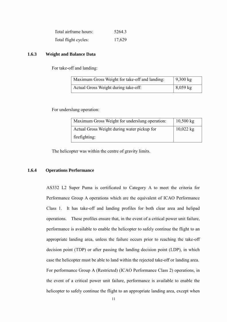
1.6.3 Weight and Balance Data
For take-off and landing:
Maximum Gross Weight for take-off and landing: 9,300 kg
Actual Gross Weight during take-off: 8,059 kg
For underslung operation:
Maximum Gross Weight for underslung operation: 10,500 kg
Actual Gross Weight during water pickup for
firefighting:
10,022 kg
The helicopter was within the centre of gravity limits.
1.6.4 Operations Performance
AS332 L2 Super Puma is certificated to Category A to meet the criteria for
Performance Group A operations which are the equivalent of ICAO Performance
Class 1. It has take-off and landing profiles for both clear area and helipad
operations. These profiles ensure that, in the event of a critical power unit failure,
performance is available to enable the helicopter to safely continue the flight to an
appropriate landing area, unless the failure occurs prior to reaching the take-off
decision point (TDP) or after passing the landing decision point (LDP), in which
case the helicopter must be able to land within the rejected take-off or landing area.
For performance Group A (Restricted) (ICAO Performance Class 2) operations, in
the event of a critical power unit failure, performance is available to enable the
helicopter to safely continue the flight to an appropriate landing area, except when
11
the failure occurs early during the take-off manoeuvre or late in the landing
manoeuvre, in which cases a forced landing may be required.
1.6.5 Engine Controls
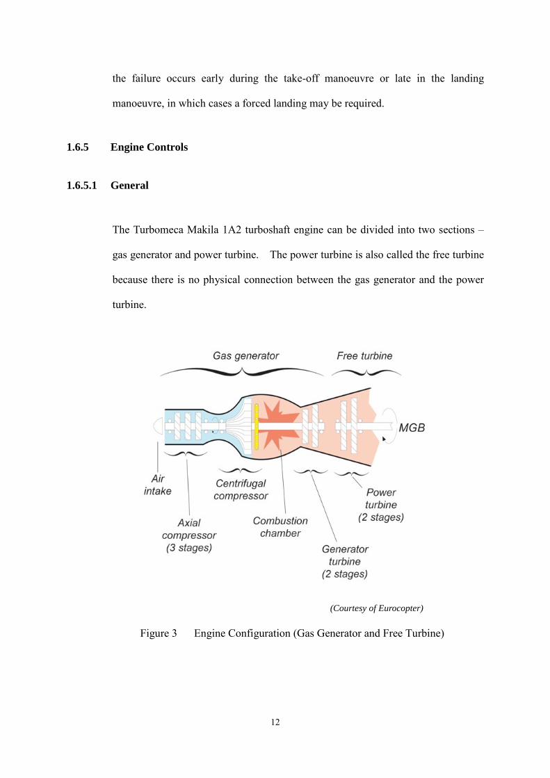
1.6.5.1 General
(Courtesy of Eurocopter)
Figure 3 Engine Configuration (Gas Generator and Free Turbine)
12
The Turbomeca Makila 1A2 turboshaft engine can be divided into two sections –
gas generator and power turbine. The power turbine is also called the free turbine
because there is no physical connection between the gas generator and the power
turbine.
1.6.5.2 Digital Engine Control Unit
Each engine is equipped with a digital engine control unit (DECU) which controls
and monitors the engine operations. There is cross link between the two DECUs.
Irrespective of the power required for flight, the DECU together with the
hydro-mechanical control unit (HMU) maintains the free turbine rotational speed
(NF) constant by varying the NG, hence on the constant power developed by the
engine. The free turbine is connected to the MGB by means of an
engine-to-MGB coupling shaft. A safety system is in place to provide overspeed
protection for the free turbine.
1.6.5.3 Free Turbine Overspeed Safety System
There are three toothed wheels on the free turbine shaft. The wheels rotate in
front of three pairs of sensors. The signals from sensors F’2 and F’3 are used by
the "NF overspeed" safety device. Should the engine-to-MGB coupling shaft
break, the free turbine rotating with no load races. To prevent the free turbine to
disintegrate under the effect of very high centrifugal forces, an automatic free
turbine overspeed safety system is in place. When the free turbine speed reaches
121.5 % of its nominal speed, the detection logic of the safety system cuts off the
fuel injected into the engine and the engine will be shut down automatically.
Moreover, this control logic will inhibit the shutting down of the second engine and
restarting of the engine shut down.
13
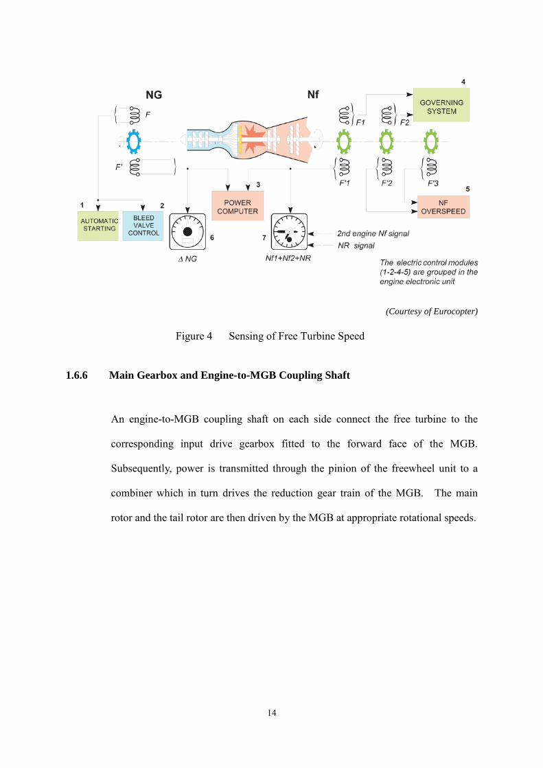
(Courtesy of Eurocopter)
Figure 4 Sensing of Free Turbine Speed
1.6.6 Main Gearbox and Engine-to-MGB Coupling Shaft
An engine-to-MGB coupling shaft on each side connect the free turbine to the
corresponding input drive gearbox fitted to the forward face of the MGB.
Subsequently, power is transmitted through the pinion of the freewheel unit to a
combiner which in turn drives the reduction gear train of the MGB. The main
rotor and the tail rotor are then driven by the MGB at appropriate rotational speeds.
14

(Courtesy of Eurocopter)
Figure 5 Free turbine to MGB connection
(Courtesy of Eurocopter)
Figure 6 Free Turbine to MGB Coupling Shaft and Freewheel Connection
15

1.6.7 Freewheel Unit
1.6.7.1 Ramp and roller type
The freewheel is a ‘ramp and roller’ unit. This type of freewheel depends on
wedging action to transmit torque. Cylindrical freewheel rollers are used to
transmit torque from the input (freewheel shaft) to the output member (freewheel
pinion).
The freewheel shaft is an equilateral polygon with the 12 ramps and equal number
of rollers. The rollers are positioned on the ramps by a cage which is positioned
by a spring so that the rollers touch both the ramps and the freewheel pinion. The
cage holds the rollers towards the upper end of the ramps to minimise roller slip
during engagement. Each ramp has a flat surface when it is brand new. A
schematic of the freewheel unit and its cross section are presented in Appendix 1.
(Courtesy of Eurocopter)
Figure 7 New Freewheel Shaft
16
1.6.7.2 Engagement and Disengagement between MGB and Engine
When torque is applied to the freewheel shaft so as to force the rollers up the ramps,
the rollers become wedged between the freewheel shaft and the freewheel pinion,
thereby locking these members together allowing the engine to drive the MGB.
When the freewheel pinion attempts to rotate faster than the freewheel shaft or the
engine torque is lost the rollers roll out from the wedged position and slide on the
freewheel shaft, thereby decoupling the freewheel shaft from the freewheel pinion.
Any factors breaking the locking of these members, when the freewheel unit is in
driving mode, will contribute to a disconnect between the MGB and the
corresponding engine. When a freewheel unit is disengaged, the corresponding
engine is disconnected from the MGB. The rotors and accessories are then driven
by the remaining operating engine.
1.6.8 Emergency Floatation Gear
The Super Puma is fitted with an emergency flotation gear which comprises four
float assemblies. It is designed to maintain the aircraft afloat after ditching
allowing precious time for evacuation. The buoyancy is ensured by four floats
simultaneously inflated with compressed helium from the pressurised bottles prior
to ditching. Once the personnel onboard have evacuated, the aircraft may be
towed on the water at a maximum speed of 4 knots.
The inflation of the floats is manually controlled by an electrical firing system. The
control unit of the system is installed on the right hand side of the centre console in
17
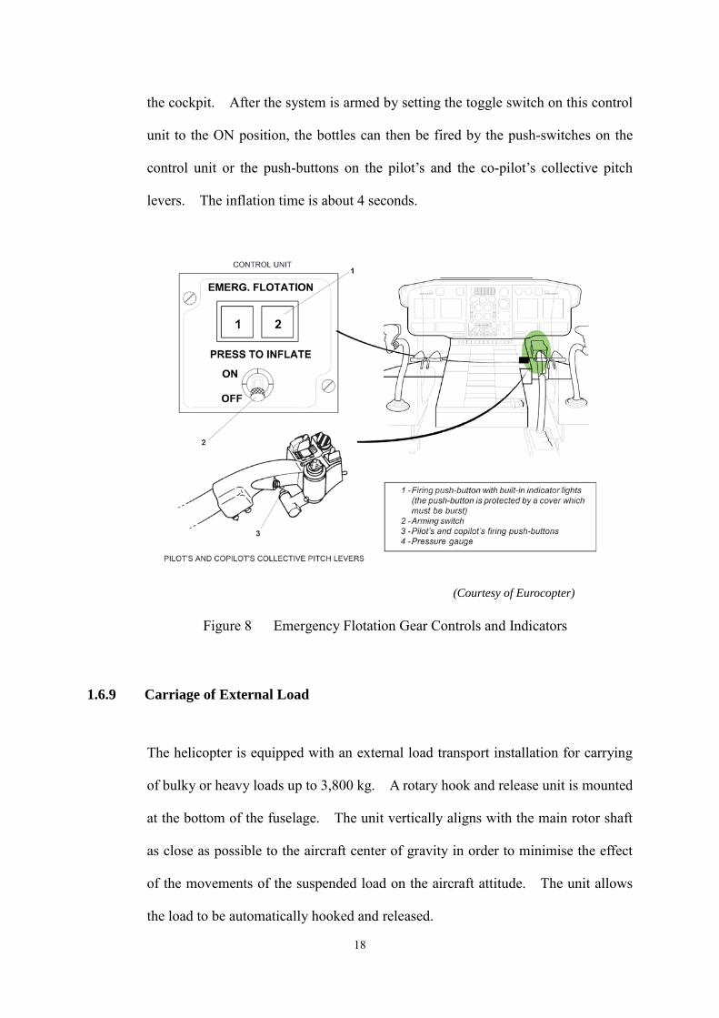
the cockpit. After the system is armed by setting the toggle switch on this control
unit to the ON position, the bottles can then be fired by the push-switches on the
control unit or the push-buttons on the pilot’s and the co-pilot’s collective pitch
levers. The inflation time is about 4 seconds.
(Courtesy of Eurocopter)
Figure 8 Emergency Flotation Gear Controls and Indicators
1.6.9 Carriage of External Load
The helicopter is equipped with an external load transport installation for carrying
of bulky or heavy loads up to 3,800 kg. A rotary hook and release unit is mounted
at the bottom of the fuselage. The unit vertically aligns with the main rotor shaft
as close as possible to the aircraft center of gravity in order to minimise the effect
of the movements of the suspended load on the aircraft attitude. The unit allows
the load to be automatically hooked and released.
18
In an emergency such as engine failure, the hook on the unit can be opened
electrically by pressing a push-button on the pilot’s and copilot’s cyclic sticks.
The load can then be dropped instantly in flight. These controls are active only
when the mission selector is set to SLING position. The pilot can also release the
load mechanically by means of a trigger switch on the collective pitch lever.
A digital load dynamometer is mounted with the hook to measure the weight of the
carried load. The hook configuration and the "weight transported" are indicated
by the Navigation and Mission Display (NMD) in front of each pilot.
1.6.10 Aircraft Recording and Monitoring System
B-HRN was equipped with a Eurocopter Aircraft Recording and Monitoring
System (EuroARMS). The EuroARMS incorporates three systems and functions,
namely a solid state cockpit voice and flight data recorder (SSCVFDR), the Usage
Monitoring System (UMS) and the Health and Usage Monitoring System (HUMS).
The UMS records operating time, flying time, landing count, engine cycle count,
main rotor speed (NR) cycle and torque cycle count. It also provides continuous
exceedance monitoring for MGB over-torque, engine exceedance and NR
exceedance. In addition, it record alarms and failures displayed by onboard
system (aircraft status) and alarms of EuroARMS equipment (system status).
The HUMS makes it possible to record vibration data from sensors that are
strategically placed around the helicopter. The HUMS monitors vibration from
major mechanical component such as engine, engine-to-MGB coupling shafts,
19
MGB gears, shaft and bearings, ancillary modules, intermediate gearbox (IGB) and
tail gearbox (TGB) gears, shafts and bearings, oil cooler fan (OCF), and main and
tail rotors. The data can then be retrieved and analysed to detect incipient defects
in the major components of the helicopter, before these defects can become a
hazard to flight. The system may also be used to improve the reliability of the
airframe and its components by identifying sources of abnormal or increasing
vibration. HUMS data trending is predicted on the comparison of data that has
been obtained during as stable and as consistent a period of flight as practicable.
For this reason, data is most typically recorded when either on the ground or in the
cruise.
1.6.11 Fuel Information
After the accident, fuel samples were taken from the helicopter for analysis. The
analysis report concluded that the fuel samples conformed to the specification of
Jet A-1.
1.6.12 Maintenance Records
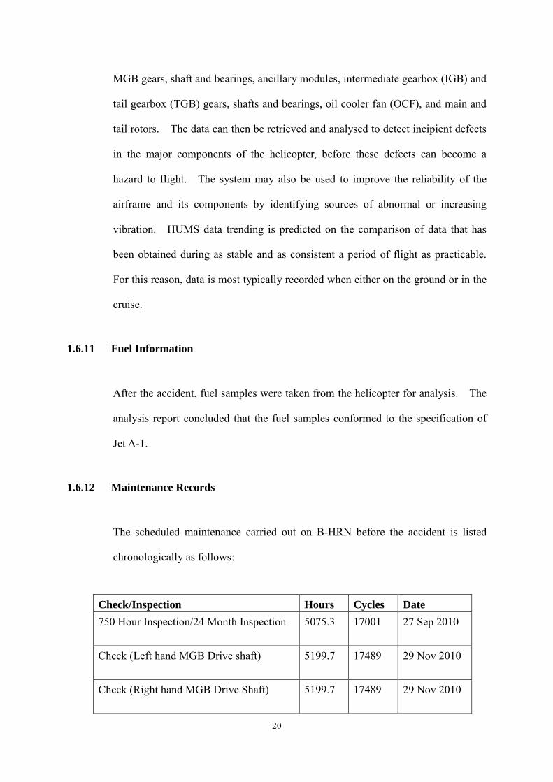
The scheduled maintenance carried out on B-HRN before the accident is listed
chronologically as follows:
Check/Inspection Hours Cycles Date 750 Hour Inspection/24 Month Inspection 5075.3 17001 27 Sep 2010
Check (Left hand MGB Drive shaft) 5199.7 17489 29 Nov 2010
Check (Right hand MGB Drive Shaft) 5199.7 17489 29 Nov 2010
20
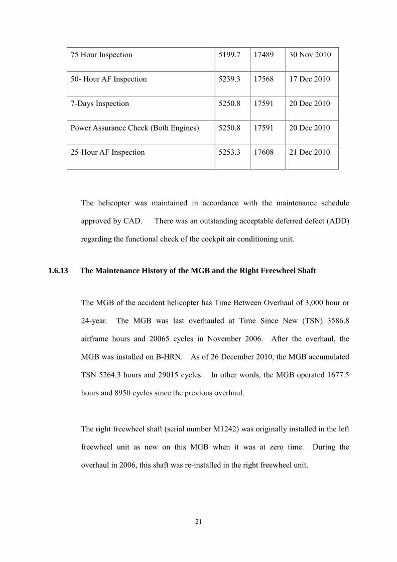
75 Hour Inspection 5199.7 17489 30 Nov 2010
50- Hour AF Inspection 5239.3 17568 17 Dec 2010
7-Days Inspection 5250.8 17591 20 Dec 2010
Power Assurance Check (Both Engines) 5250.8 17591 20 Dec 2010
25-Hour AF Inspection 5253.3 17608 21 Dec 2010
The helicopter was maintained in accordance with the maintenance schedule
approved by CAD. There was an outstanding acceptable deferred defect (ADD)
regarding the functional check of the cockpit air conditioning unit.
1.6.13 The Maintenance History of the MGB and the Right Freewheel Shaft
The MGB of the accident helicopter has Time Between Overhaul of 3,000 hour or
24-year. The MGB was last overhauled at Time Since New (TSN) 3586.8
airframe hours and 20065 cycles in November 2006. After the overhaul, the
MGB was installed on B-HRN. As of 26 December 2010, the MGB accumulated
TSN 5264.3 hours and 29015 cycles. In other words, the MGB operated 1677.5
hours and 8950 cycles since the previous overhaul.
The right freewheel shaft (serial number M1242) was originally installed in the left
freewheel unit as new on this MGB when it was at zero time. During the
overhaul in 2006, this shaft was re-installed in the right freewheel unit.
21
1.6.14 AS332 L2 Maintenance Programme (PRE)
1.6.14.1 Service Life Limit
According to the PRE, the freewheel shaft has a service life limit (SLL) of 50,000
hours. Service life limited components are exposed to fatigue damage due to
in-service stress, and whose failure may jeopardise the aircraft safety. There are
no other airworthiness limits for the freewheel shaft in the PRE. In addition, the
Time Between Overhaul (TBO) of the MGB with provision of HUMS is 3,000
flight hours or 24-year, whichever is sooner.
1.6.14.2 Torque Variation Cycles
The number of torque variation cycles, according to the PRE, varies significantly
with the multiple missions that can be performed by an AS332 L2 Super Puma.
For examples, external load carrying operations can involve a very large number of
torque cycles, up to 60 per hour, while passenger carrying flights of 1 hour only
lead to 1 torque cycle per hour. Therefore, no fixed number has been specified by
Eurocopter in order to avoid premature removal of components that are little
exposed to torque variations. The lifetime of the components concerned is
specified in a number of cycles. Therefore, the number of torque cycles logged
must be monitored carefully and counted as follows:
1 LANDING WITH OR WITHOUT STOPPING THE ROTOR = 1 CYCLE.
1 EXTERNAL LOAD CARRYING OPERATION = 2 CYCLES.
The cycles related to external load carrying operation must be added to the landing
operation cycles.
22
1.7
1.6.15 Ramp Wear Depth Limit of Freewheel Shaft
The wear limit of the ramp surface of the freewheel shaft is published in the Repair
Manual (MRV). In November 2006, the maximum allowable wear limit was 0.05
mm. In February 2007, Eurocopter issued Letter to Repair Stations (LR) No.214
to Repair Stations to tighten the limit from 0.05 mm to 0.005 mm.
LR No.214 was issued because Eurocopter identified major dents on the ramps of
the freewheel shafts in an MGB under overhaul. These dents may impair correct
freewheel operation.
Meteorological Information
At the time of the accident, Hong Kong was influenced by a dry winter monsoon
which maintained a fine and dry weather. The visibility was more than 10 km
with clear sky. The Corrected Mean Sea Level Atmospheric Pressure (QNH) was
1021 hPa. The one-minute mean wind speed, recorded by the Hong Kong
Observatory (HKO) at the Sha Tin Automatic Weather Station (the nearest station
to the accident site) at 0237 hrs (1037 hrs), was 7.4 knots and the 1-minute mean
wind direction was 63 degree.
Shortly after the accident, extra meteorological observations were made at the
HKO Headquarters and HKIA, and the collected weather information was as
follows:
23
(i) Meteorological observation made at 0248 UTC on 27 December 2010 at
HKO Headquarters in Tsim Sha Tsui, Kowloon
Wind Direction: 100 degrees
Wind Speed: 3.9 knots
Visibility: 27 km
Temperature: 14.2 ºC
Dew point temperature: 5.7 ºC
MSL pressure: 1021.1 hPa
Cloud: Nil
Weather: No significant weather
(ii) Meteorological observation made at 0245 UTC on 27 December 2010 at
HKIA
Wind Direction: 320 degrees, wind direction varied from 280 degree to
360 degree during the 10 minutes preceding the observation
Wind Speed: 6 knots
Visibility: 10 km or more
Temperature: 15 ºC
Dew point temperature: 2 ºC
QNH: 1021 hPa
Cloud: No cloud below 5000 feet
Weather: No significant weather
24
1.8 Aids to Navigation
Ground-based navigation aids and on board navigation aids and their serviceability
were not a factor in this occurrence.
1.9 Communications
Before the helicopter ditched, the co-pilot had made a "MAYDAY" call which was
acknowledged by ATC Tower at the Hong Kong International Airport. An aircraft
accident alert was then initiated by ATC Tower. Communications between the
crew and ATC was not a factor in this occurrence.
1.10 Aerodrome Information
It is not relevant to this accident.
1.11 Flight Recorders
The aircraft was equipped with an Allied Signal AR-602C combined solid state
cockpit voice and flight data recorder, which was integrated with the EuroARMS.
The SSCVFDR complied with European Organisation for Civil Aviation
Electronics (EUROCAE) Document ED-55 and can record 10 hours of flight data
of 214 parameters at a rate of 128 words per second.
The SSCVFDR has four voice channels (three for crew and one for area) and is
capable of 60 minutes of record duration. For the installation on this helicopter,
only two crew channels plus the area channel are utilised. The two crew channels
25
are narrow band and they detect the voice of the pilot and the co-pilot through their
headset microphones. The area channel is a wide band channel and it captures all
the audio signals generated in the cockpit acoustic environment via an area
microphone on the aft cockpit ceiling. The audio signals captured by the area
microphone are transmitted directly into the cockpit voice recorder (CVR). Those
signals picked up through the crew microphones are acquired by a summing
amplifier and then input into the CVR.
After the accident, the recorder was recovered without any damage. It was later
replayed and the voice recording and the flight data were retrieved successfully
using normal replay techniques, with the assistance from Eurocopter. The last 10
hours of aircraft data, together with the last hour of audio from the pilots and the
aircrewman, were downloaded for the investigation.
1.12 Site and Aircraft Examination
1.12.1 Accident Site
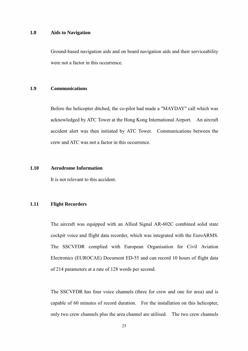
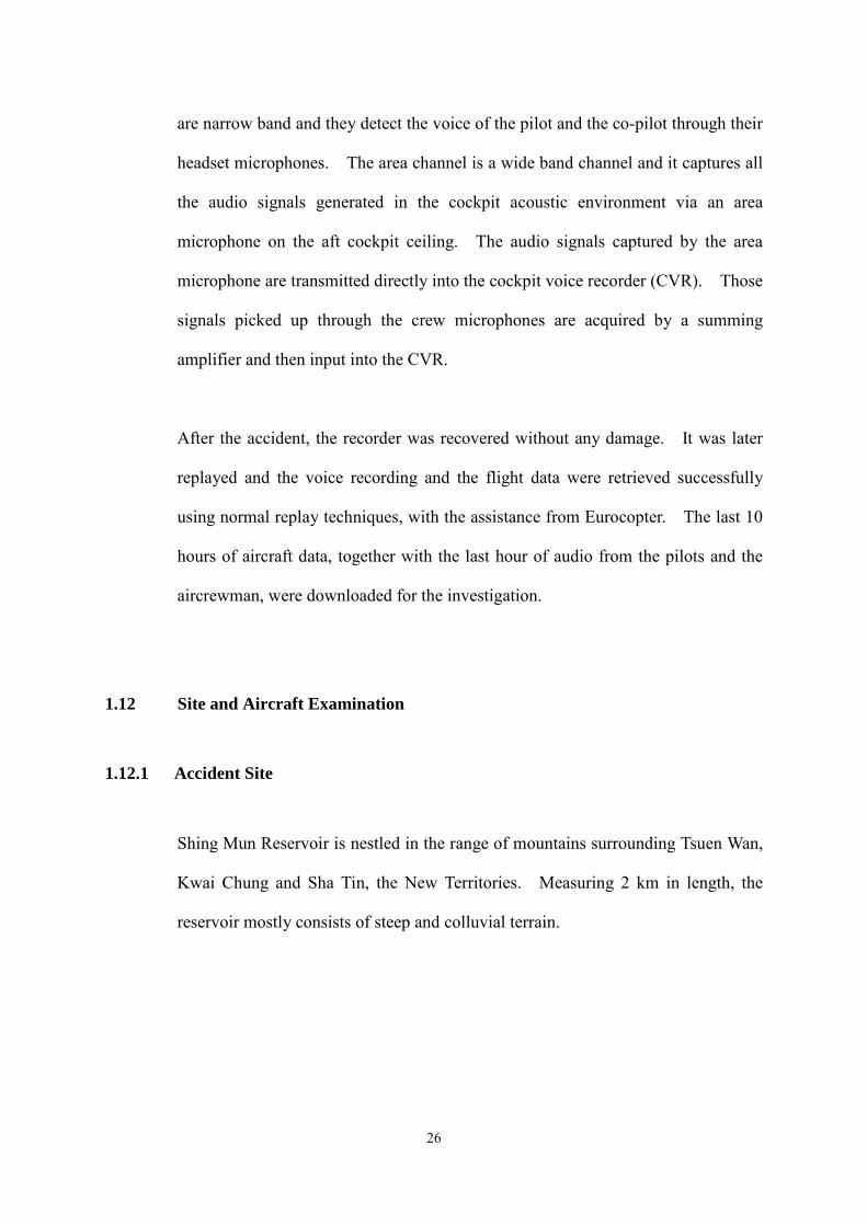
Shing Mun Reservoir is nestled in the range of mountains surrounding Tsuen Wan,
Kwai Chung and Sha Tin, the New Territories. Measuring 2 km in length, the
reservoir mostly consists of steep and colluvial terrain.
26
(Courtesy of Lands Department, HKSARG)
Figure 9 Landscape of Shing Mun Reservoir
(Courtesy of Lands Department, HKSARG)
Figure 10 Contour of Shing Mun Reservoir
27
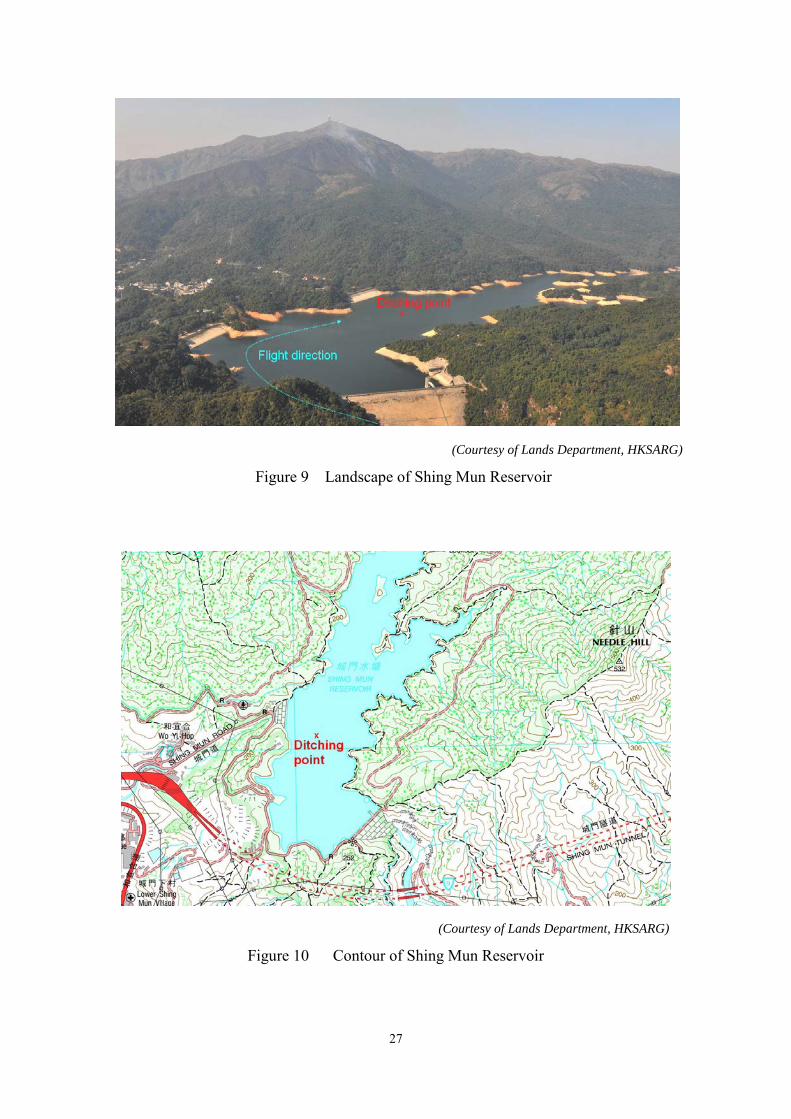
1.12.2 Helicopter Examination
The helicopter ditched in a controlled manner with the four emergency floats
deployed and fully inflated, and it was then kept afloat. There was no structural
damage to the helicopter caused by the accident. Some of the airframe, electrical
and electronic components were damaged due to being submerged into water.
The helicopter was rescued from the reservoir two days later and transported back
to the GFS Headquarters for further investigation.
Figure 11 B-HRN on Floats and Secured
1.13 Medical Information
The three crew members were not injured in the ditch. They exited the helicopter
and swam ashore with inflated life jackets. They were then sent to a hospital for
medical examination and were later discharged.
28
1.14 Fire
There was no evidence of fire in flight or after the helicopter ditched.
1.15 Survival Aspects
1.15.1 Emergency Floatation Gear
After the helicopter ditched, the crew decided not to jettison the cockpit doors.
They evacuated the helicopter through the cabin exit instead because they were
concerned about the danger of the jettisoned cockpit doors cutting and damaging
the four floatation bags located just outside the cockpit doors.
The cabin floor was still dry when they left the helicopter as the floats were strong
and effective, and water had not entered the cabin. Deciding to swim to the
western dam wall, they inflated the life jackets after jumping into the water. It
took the crew about 20 minutes to reach the western dam wall and climbed up the
wall to arrive at a track that offered more protection from the cold.
1.15.2 Search and Rescue
The emergency rescue units arrived at the scene about 10 minutes later to provide
assistance. Since the helicopter was kept afloat by the four floats, the hydrostatic
switch at the cabin floor structure and the water detector in the casing of the
Automatic Deployable Emergency Locator Transmitter (ADELT) were not in
contact with water. Therefore, the ADELT was not activated after ditching.
29
1.16 Tests and Research
After the accident, the SSCVFDR, the EuroARMS computer and the two DECUs
were removed from the helicopter. The flight data and the voice recordings in the
SSCVFDR were later retrieved with the assistance from Eurocopter. Furthermore,
the voice recording of the cockpit ambient, the EuroARMS computer and the two
DECUs were sent to the BEA for spectral and data analysis with assistance from
Eurocopter and Turbomeca. In addition, the MGB of the helicopter was sent back
to Eurocopter for detailed examination with the process being monitored by the
BEA.
1.17 Organisational and Management Information
1.17.1 The Government Flying Service
The GFS is a disciplined service department of the Government of the Hong Kong
Special Administrative Region. As of 31 December 2011, it has an establishment
of 227 personnel responsible for flight operations, aircraft maintenance and
administration. The GFS Headquarters is located at the south-western corner of
HKIA. It provides flying services, mainly for firefighting, search and rescue, air
ambulances, law enforcement agencies' operations and the carriage of VIPs. A
mixed helicopter fleet was operated at HKIA, comprising three Eurocopter AS332
L2 Super Puma and four EC155B1 helicopters. The Super Puma was introduced to
service during the period between late 2001 / early 2002 and the EC155B1 was
introduced during the period between late 2002 / early 2003. The GFS also
operates two Jetstream 41 fixed wing aeroplanes.
30
1.17.2 Firefighting Operations
The AS332 L2 Super Puma helicopters are used for assisting the Agriculture,
Fisheries and Conservation Department and the Fire Services Department on
countryside fire suppression operations when the needs arise. They can carry
large loads of water by using helicopter buckets. In addition to the standard fire
bucket system, the Super Puma helicopters can also be fitted with a ‘belly tank'
with its own suction pump and fire foam delivery system to enhance the
firefighting capability. According to the figures published by the GFS, on
average, the helicopters fly approximately 300 hours in response to firefighting call
outs every year.
1.17.3 GFS Operations Manual
GFS Operations Manual Volume 3, “AS332 L2 Operating Procedures and MEL”,
requires that the Pilot Flying, among other duties, to carry out a brief including
actions to be taken in case of an emergency such as an engine failure during
take-off. For underslung load operations, it states that single engine failures at
any point above the Safe Single Engine Speed (Blue Line + 10) will normally
allow the load to be retained initially. In firefighting operations with water bucket
however, aircraft emergencies such as engine, transmission or tail rotor failures
may cause immediate rapid descent of the aircraft and may require immediate
bucket jettison. At any point above the Safe Single Engine Speed
(Blue Line + 10), the helicopter can continue in flight. At any point below it, the
helicopter has to make a force landing (or ditch).
31
1.17.4 Flight Manual Supplement SUP.5
This Supplement contains additional information on Automatic Pilot System SAR
Modes. It covers normal and emergency procedures for the use of the automatic
functions, such as holding in hover flight with respect to the surface at a
determined height, and monitoring of the designated safety height with automatic
increase in collective pitch when the aircraft height drops below the designated
safety height. It also provides a performance chart (Figure 1 in this Supplement
Height Loss After Engine Failure at Hover Flight, see Appendix 2) for the
determination of height loss after engine failure in hover flight.
The figure shows that at a temperature of 15 ºC and an altitude of 200 feet, the
height loss, after an engine failure in nil wind and at a calculated All Up Weight of
9,087 kg with the underslung fire bucket, is 210 feet, and for an All Up Weight of
7,479 kg without the underslung fire bucket the height loss is 60 feet.
1.18 Additional Information
There was no other factual information that was relevant to the circumstances
leading up to the occurrence.
32
2 ANALYSIS
2.1 General
During lifting the filled up water bucket at Shing Mun Reservoir in the sixth
operation and when the helicopter was on transition to forward flight, No.2 engine
shut down automatically due to a free turbine overspeed signal. The captain
decided to ditch the helicopter into the reservoir.
Based on these facts, the investigation team identified the flight operations and the
helicopter systems to be investigated and analysed.
2.2 Flight Operations
2.2.1 Crew Qualifications
The pilot accumulated 3,373 hours on helicopters and 1,918 hours on this type.
The co-pilot had 308 hours on helicopters and 170 hours on this type. They were
properly licensed, medically fit and adequately rested to operate the flight. They
were also entirely familiar with the terrain surrounding Shing Mun Reservoir.
The pilots’ actions in the accident flight and their post-accident statements
indicated that their knowledge and understanding of the helicopter systems was
adequate.
It is believed that their experience level and rest periods do not have any bearing on
the causes of the accident.
33
2.2.2 Weather
From the weather information recorded at the Sha Tin Automatic Weather Station
and the two meteorological observations made after the accident, it could be seen
that the wind at the lower level was light and variable, generally from an easterly
direction.
According to the pilot, the wind was from the north-east at height. Lower down
at the reservoir the wind was modified, some of it curling down the south-easterly
way, some of it coming down the north-easterly way. The wind was light and
sometimes showing zero. This showed that at the southern side of the reservoir
the wind was light from a south-easterly direction and in the north it was from a
north-easterly direction, with a demarcation line just about abeam the western dam
wall. Observations made from a reconnaissance flight after the accident
confirmed the pilot’s observation.
On the other hand, the flight data recorder (FDR) showed that the helicopter was in
a downwind approach to the southern part of the reservoir to pick up water. It
could be concluded here that the helicopter, when picking up water, was in a light
downwind position, and when in the transition to forward flight, when it passed the
western dam wall, at the demarcation line, the helicopter would be in an into wind
condition.
As the wind was light and the direction was modified by the surrounding terrain,
the decision by the pilot to approach and take off in a north-easterly direction,
34
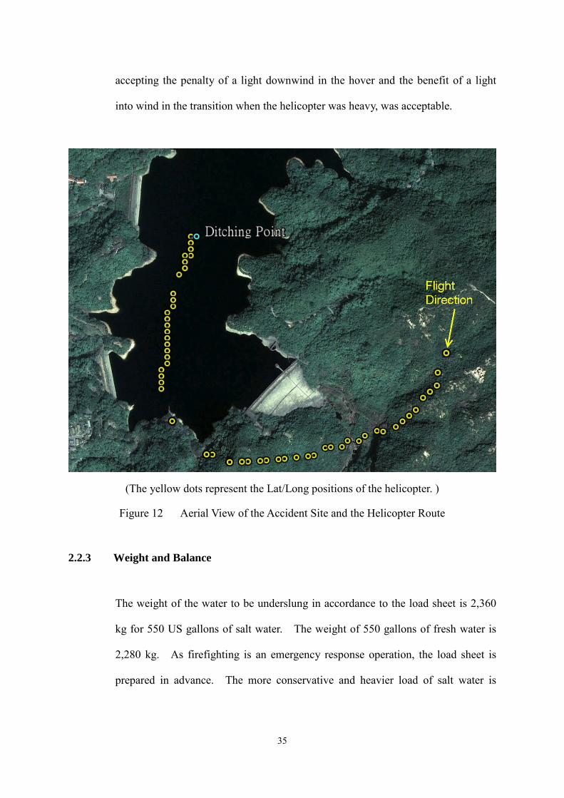
accepting the penalty of a light downwind in the hover and the benefit of a light
into wind in the transition when the helicopter was heavy, was acceptable.
(The yellow dots represent the Lat/Long positions of the helicopter. )
Figure 12 Aerial View of the Accident Site and the Helicopter Route
2.2.3 Weight and Balance
The weight of the water to be underslung in accordance to the load sheet is 2,360
kg for 550 US gallons of salt water. The weight of 550 gallons of fresh water is
2,280 kg. As firefighting is an emergency response operation, the load sheet is
prepared in advance. The more conservative and heavier load of salt water is
35
used for the calculation, as the nearest source of water cannot be ascertained until
after the callout or when the helicopter reaches the site of the fire.
Fresh water at Shing Mun reservoir was used, in this case, therefore the calculated
Gross Weight at the first pickup of water should be 9,942 kg if 550 gallons of fresh
water was picked up. However, the underslung weight of the bucket, according to
the data recorded in the FDR, showed a variation of between 1,837 kg and 1,379
kg just before No.2 engine shut down. This variation of weight might be due to
the positive and negative gravity forces acting on the bucket while it was being
underslung in flight. The difference between the calculated and the actual
recorded on the FDR was that the calculation of the load sheet used the
conservative figure assuming that the bucket was filled to the brim, this might not
be the case in an actual situation, where the bucket might not be filled to the brim,
and there might be spillage during the pickup process. After No.2 engine shut
down, the weight of the bucket of water as shown on the FDR varied between
1,343 kg and 0 kg. The first 0 kg was recorded when the helicopter was 19 feet
on the radio altimeter, when the bucket might have completely separated from the
helicopter after being jettisoned.
If we took the median of the maximum weight of 1,837 kg and the minimum
weight of 1,379 kg of the underslung water bucket as recorded in the FDR, the
median weight of the underslung water bucket would be as 1,608 kg. The Gross
Weight of the helicopter just prior to the shutdown of No.2 engine would be
calculated as follows:
36
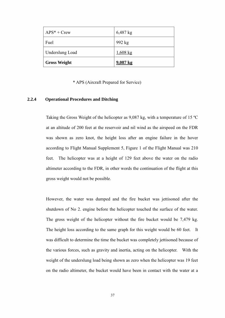
APS* + Crew 6,487 kg
Fuel 992 kg
Underslung Load 1,608 kg
Gross Weight 9,087 kg
* APS (Aircraft Prepared for Service)
2.2.4 Operational Procedures and Ditching
Taking the Gross Weight of the helicopter as 9,087 kg, with a temperature of 15 ºC
at an altitude of 200 feet at the reservoir and nil wind as the airspeed on the FDR
was shown as zero knot, the height loss after an engine failure in the hover
according to Flight Manual Supplement 5, Figure 1 of the Flight Manual was 210
feet. The helicopter was at a height of 129 feet above the water on the radio
altimeter according to the FDR, in other words the continuation of the flight at this
gross weight would not be possible.
However, the water was dumped and the fire bucket was jettisoned after the
shutdown of No 2. engine before the helicopter touched the surface of the water.
The gross weight of the helicopter without the fire bucket would be 7,479 kg.
The height loss according to the same graph for this weight would be 60 feet. It
was difficult to determine the time the bucket was completely jettisoned because of
the various forces, such as gravity and inertia, acting on the helicopter. With the
weight of the underslung load being shown as zero when the helicopter was 19 feet
on the radio altimeter, the bucket would have been in contact with the water at a
37
height of about 30 to 40 feet above water (the length of the underslung bucket with
the sling, taking a swing of the underslung bucket into consideration).
It would therefore be reasonable to take the average the total height loss of the
helicopter at the median weight of the underslung fire bucket before No.2 engine
shut down, and the height loss without the underslung fire bucket to approximate
the height loss of the helicopter, in order to determine the possibility of continuing
the flight.
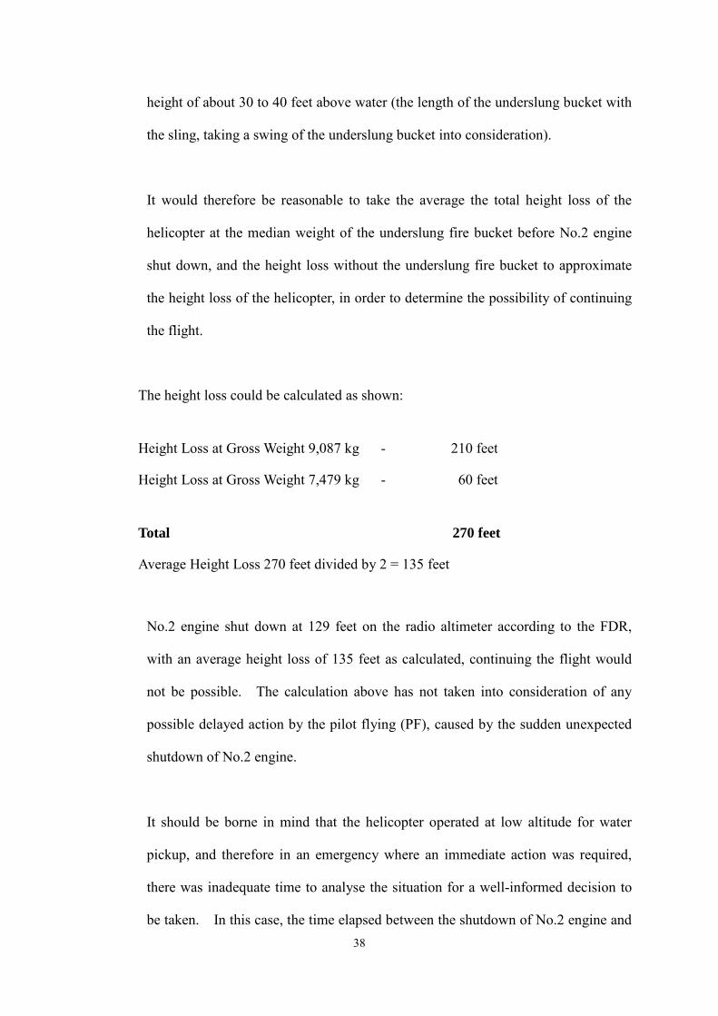
The height loss could be calculated as shown:
Height Loss at Gross Weight 9,087 kg - 210 feet
Height Loss at Gross Weight 7,479 kg - 60 feet
Total 270 feet
Average Height Loss 270 feet divided by 2 = 135 feet
No.2 engine shut down at 129 feet on the radio altimeter according to the FDR,
with an average height loss of 135 feet as calculated, continuing the flight would
not be possible. The calculation above has not taken into consideration of any
possible delayed action by the pilot flying (PF), caused by the sudden unexpected
shutdown of No.2 engine.
It should be borne in mind that the helicopter operated at low altitude for water
pickup, and therefore in an emergency where an immediate action was required,
there was inadequate time to analyse the situation for a well-informed decision to
be taken. In this case, the time elapsed between the shutdown of No.2 engine and 38
the helicopter touching the water surface was 30 seconds. The pilot had to decide
within the first couple of seconds, the action to be taken in order to achieve a
successful fly-away or to execute a safe forced landing. Due to the time
constraints, the immediate action to be taken was normally decided in the brief, in
order that time might not be wasted in case of the failure of an engine.
It should also be noted that within the 30 seconds the PF assisted by the pilot not
flying (PNF), had to fly the helicopter, jettison the underslung bucket, activate the
floatation system and to put out a “Mayday” call. In this case, the aircrewman on
hearing the captain calling “Power Loss going for ditching” called “Dump, Dump,
Dump” and dumped the water to get rid of the excess weight from the helicopter, to
enable a better helicopter configuration for a safe forced landing. According to
the captain, the crew had been briefed the emergency procedures for power loss,
and he decided to ditch in case of power loss before “blue line + 10”. Blue line is
a line in blue, calculated by the Flight Management System and indicated in the
Airspeed Indicator that showed the minimum airspeed, where at the conditions
given, the helicopter would be able to achieve level flight. The figure “+10” was
the airspeed above the blue line where the helicopter would be able to achieve a
climb of 100 feet per minute. In this case, the location of the blue line would be at
approximately 40 knots. Volume 3, Chapter 5 Paragraph A.a of the Operations
Manual states that “SE (single engine) failures at any point above the Safe Single
Engine speed (“Blue Line + 10”) would normally allow the load to be retained
initially.”
The terrain surrounding Shing Mun reservoir is mountainous. The reservoir is
long and narrow at an altitude of about 600 feet, with a north-easterly alignment.
39
The water pickup spot is located in the south eastern side of the reservoir, about
one and a half kilometers is the north eastern end of the reservoir. Further up to the
north east of the reservoir about 2 kilometres away is Lead Mine Pass at about
1,500 ft, the lowest part of the terrain in that direction. In the eastern side are hills
up to 1,500 feet and to the west is Tai Mo Shan rising up to 3,000 feet. Given the
conditions of the terrain and the high Gross Weight of the helicopter with the
underslung fire bucket, it is reasonable that the crew decided that they would ditch
the helicopter at an airspeed below “Blue Line + 10”.
2.2.5 Helicopter Performance
In firefighting operations, normally, only Performance Group A (Restricted)
(Performance Class 2) operations could be carried out due the high gross weight
required in transporting the maximum amount of water possible to fight a fire.
This was an accepted international practice for emergency response operations
where the acceptable risk was higher.
Only during the time that the helicopter is picking up water and before its
subsequent acceleration the helicopter may not continue the flight in the event of
an engine failure. At other time, even with the fire bucket filled, the helicopter is
capable to continue flying without jettisoning the bucket after an engine failure.
2.3 Survivability
After the helicopter ditched with the floats fully inflated, the captain called for the
General Cut Out to be pulled, this action would shut down the other engine and
isolate all the fuel and electrical systems except the emergency battery. A number
40
of electrical systems and electric lines were located at the bottom of the helicopter,
the isolation of the electrical systems would minimise the danger of any short
circuit. The rotor brake was then applied gently by the co-pilot in accordance
with the request from the captain to avoid capsizing the helicopter. After the
ditching of the helicopter the crew decided to evacuate the helicopter.
In the circumstances, the decision to ditch the helicopter was reasonable. The
crew managed to perform a safe forced landing, as the persons in the helicopter did
not suffer any injuries and the helicopter was not damaged due to the impact of the
helicopter coming into contact with the water, caused by the controlled ditching.
This was in accordance to the conditions set out in Performance Class 2 or Group A
Restricted operations.
2.4 Engineering
2.4.1 Helicopter General
The helicopter was certified and equipped in accordance with the CAD
airworthiness requirements. The helicopter had a valid Certificate of
Airworthiness in the Transport Category (Passenger). The maintenance records
indicated that the helicopter was maintained in accordance with the approved
maintenance schedule. The weight and the centre of gravity of the helicopter
were also within the prescribed limits. There was no evidence of any known
defect or malfunction in the helicopter before the flight that could have contributed
41
to the occurrence. The fuel samples taken after the accident was examined and
verified to be of the proper grade and quality, and contained no contamination.
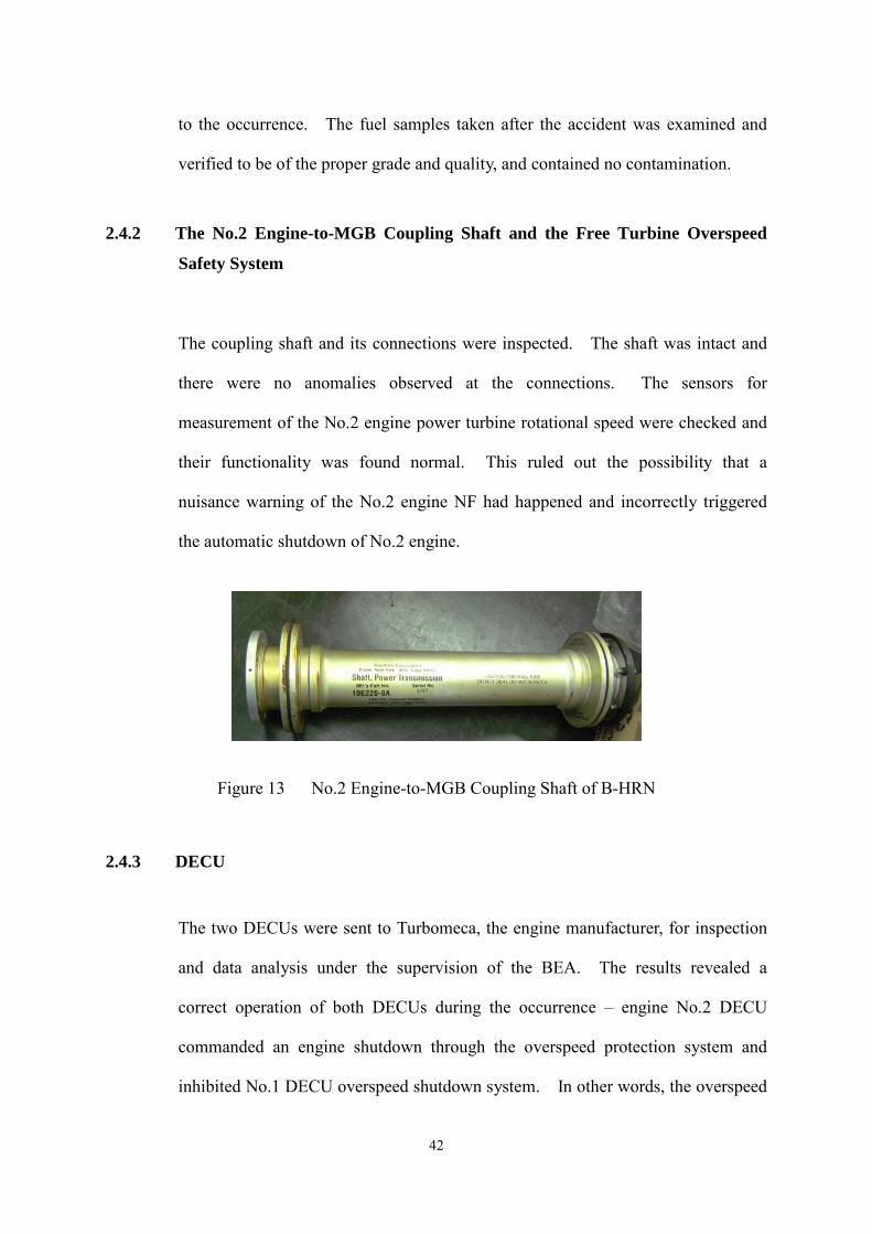
2.4.2 The No.2 Engine-to-MGB Coupling Shaft and the Free Turbine Overspeed
Safety System
The coupling shaft and its connections were inspected. The shaft was intact and
there were no anomalies observed at the connections. The sensors for
measurement of the No.2 engine power turbine rotational speed were checked and
their functionality was found normal. This ruled out the possibility that a
nuisance warning of the No.2 engine NF had happened and incorrectly triggered
the automatic shutdown of No.2 engine.
Figure 13 No.2 Engine-to-MGB Coupling Shaft of B-HRN
2.4.3 DECU
The two DECUs were sent to Turbomeca, the engine manufacturer, for inspection
and data analysis under the supervision of the BEA. The results revealed a
correct operation of both DECUs during the occurrence – engine No.2 DECU
commanded an engine shutdown through the overspeed protection system and
inhibited No.1 DECU overspeed shutdown system. In other words, the overspeed
42
function of either DECU was in compliance with the manufacturer’s technical
specifications.
2.4.4 Flight Data
The accident flight lasted about 55 minutes and the voice and data recording was
stopped after the captain called for the General Cut Out to be pulled. After the
flight data were retrieved, and the investigation team noted that there was a sudden
rise of NF of No.2 engine at 02:37:14 to 128%. There were no other anomalies in
the engine parameters except the power turbine overspeed on No.2 engine.
Since there were no anomalies on the power turbine and the engine-to-MGB
coupling shaft of No.2 engine, and the free turbine overspeed safety system, it was
believed that the ‘disconnect’ could have been caused by a slippage in the right
freewheel unit which was mechanically connected to the engine-to-MGB coupling
shaft. Therefore, the MGB and the right freewheel unit became the focus of the
investigation. The plots of the flight data (the last 33 minutes and the last three
minutes) are presented in Appendix 3 and Appendix 4 respectively.
2.4.5 Voice Recording of the Cockpit Ambient
A spectral analysis on the cockpit ambient sound recording picked up by the
cockpit area microphone was conducted by the BEA. This recording gave
relevant information regarding rotors, engines and main gear box.
43
The analysis identified a thud immediately followed by the increase in the
frequency of the NF information. While the NF reached the value of 121%, the
NG suddenly decreased as for an engine shutdown. The maximum NF observed
was 132%. There was also a sudden drop of the main gearbox frequencies during
the thud duration. The results of the spectral analysis in graphical format are
presented in Appendix 5.
The spectral analysis confirmed the NF overspeed of one of the two engines.
Although it could not be determined, by this analysis alone, whether the increase in
the power turbine rotational speed happened on No.1 or No.2 engine, together with
the SSCVFDR data it could confirm that overspeed of the power turbine of No.2
engine occurred in flight.
2.4.6 EuroARMS
The data in the EuroARMS computer and the previously downloaded data were
analysed and no anomalies were found related to this occurrence. Although
EuroARMS is an effective means of monitoring major mechanical components on
the helicopter, there are certain components, such as freewheel units, which may
not generate any detectable levels of vibration during the normal operations.
Therefore, this kind of components cannot be effectively monitored by the
EuroARMS.
2.5 Examination of the Main Gearbox
Since the power turbine of No.2 engine was connected to the right freewheel unit
in the MGB, the MGB was disassembled and examined by Eurocopter under the
44
supervision of the BEA at the Eurocopter facilities at Marignane, Marseille, France.
After the examination, there were no abnormal wear and tear observed in the MGB
by visual inspection.
Therefore, the right freewheel unit was further stripped down for detailed
examination.
2.6 Examination of the Right Freewheel Unit
According to Eurocopter, this was the first accident on AS332 L2 Super Puma due
to freewheel slippage. The freewheel unit was disassembled, the freewheel shaft,
the rollers and the cage were closely examined.
2.6.1 Freewheel Shaft
Fretting wear was observed on the right freewheel shaft at the area in contact with
the support bearings (ball bearing and roller bearing), between ramps #4 and #7
and between ramps #9 and #12. The fretting wear was caused by a known
phenomenon called the "false Brinell effect", which might occur when the MGB
was running with the freewheel engaged. In such operating conditions, the
freewheel roller bearings and the freewheel rollers did not rotate and, therefore,
vibrations inherent to MGB operation might cause this phenomenon.
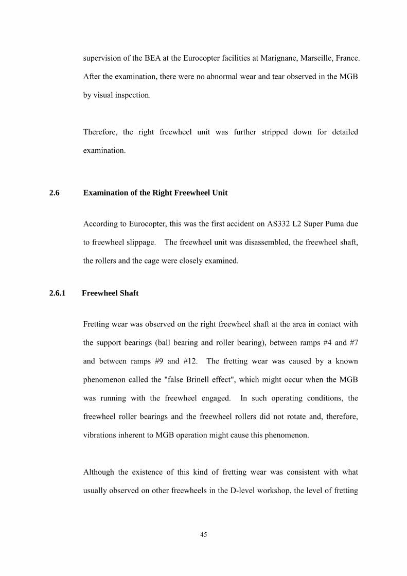
Although the existence of this kind of fretting wear was consistent with what
usually observed on other freewheels in the D-level workshop, the level of fretting
45
on this freewheel shaft was a little higher than what was usually observed during
MGB overhaul.
(Courtesy of Eurocopter)
Figure 14 Fretting Wear at the Support Area of the Freewheel Shaft
On the other hand, detailed visual inspection was conducted on the 12 ramps.
The close-up photos of them are presented in Appendix 6. The geometrical
conformity and the hardness of the freewheel shaft were checked, and they were
found in conformity with their specifications. The conditions of the freewheel
shaft were similar to other freewheel shafts observed in overhaul, except that this
freewheel shaft had a higher level of ramp wear. It should be noted that this MGB
only operated for 1,677.5 hours since the previous overhaul and its next overhaul
should be due in another 1,322.5 hours in service. It meant that the ramp wear on
this freewheel shaft grew at a rate higher than what Eurocopter had predicted in the
maintenance programme. The causes of the high growth rate of ramp wear are
further discussed in paragraph 2.8 and 2.12.
46
2.6.2 Rollers and Cage
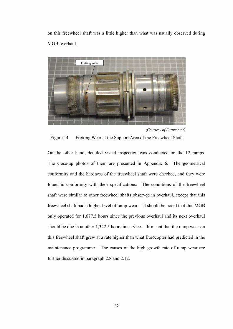
The rollers were found in conformity with the specifications. During the detailed
visual inspection, signs of contact with the ramps at the “low-wear” areas were
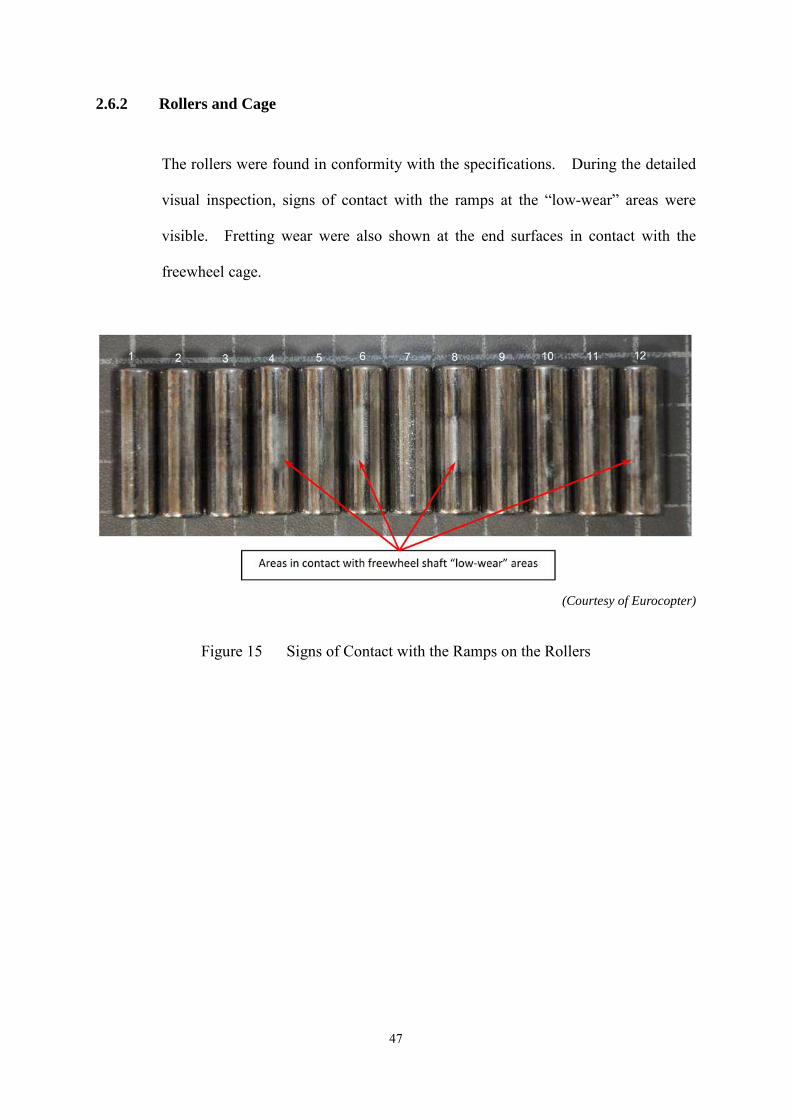
visible. Fretting wear were also shown at the end surfaces in contact with the
freewheel cage.
(Courtesy of Eurocopter)
Figure 15 Signs of Contact with the Ramps on the Rollers
47
(Courtesy of Eurocopter)
Figure 16 Wear on the Ends of the Rollers
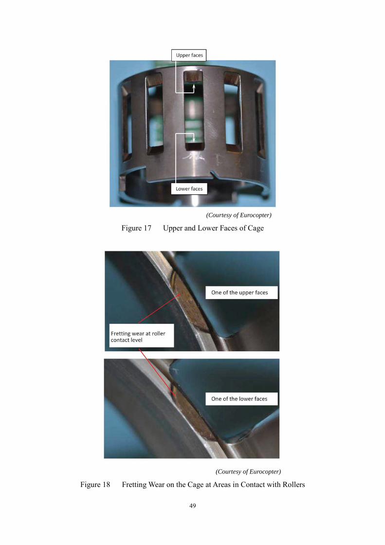
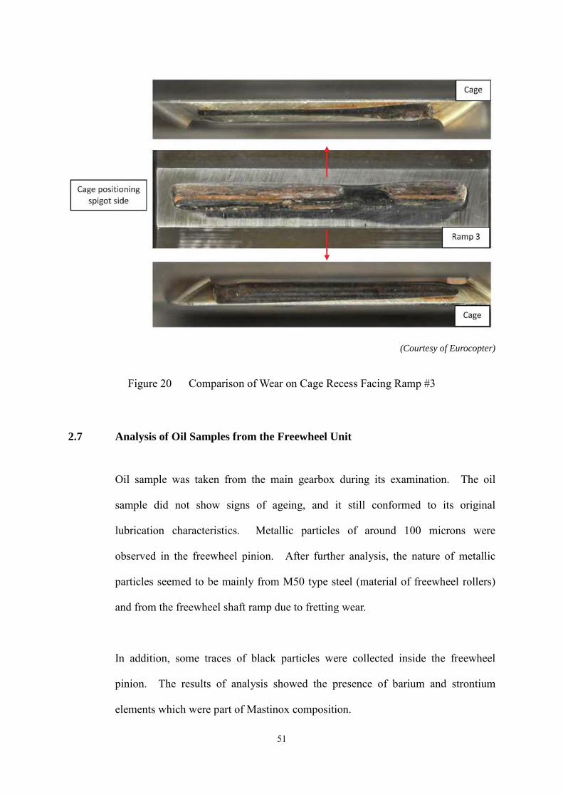
On the other hand, fretting wear was observed at the upper and lower faces of the
cage. However, the fretting wear was considered normal. In addition, the
guidance springs for the cage were also found in good conditions.
48
(Courtesy of Eurocopter)
Figure 17 Upper and Lower Faces of Cage
(Courtesy of Eurocopter)
Figure 18 Fretting Wear on the Cage at Areas in Contact with Rollers
49

Furthermore, from the wear on the lateral surfaces of the cage recess facing ramp
#1, and similarly on ramp #7, it could be observed that the roller had stayed
parallel to the ramp and the recess during the operation. The photographs of #1
ramp and cage recesses are shown as follows.
(Courtesy of Eurocopter)
Figure 19 Comparison of Wear on Cage Recess Facing Ramp #1
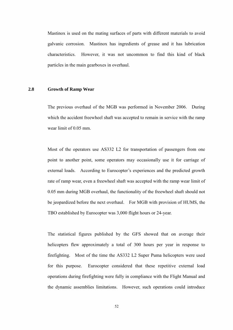
A similar comparison was carried out on ramp #3 and the cage recess. It could be
observed that the roller did not work parallel to the ramp and the cage recess,
probably due to the micro-displacement of the roller. Similar wear shapes were
also observed on ramps other than ramp #1 and #7.
50
2.7
(Courtesy of Eurocopter)
Figure 20 Comparison of Wear on Cage Recess Facing Ramp #3
Analysis of Oil Samples from the Freewheel Unit
Oil sample was taken from the main gearbox during its examination. The oil
sample did not show signs of ageing, and it still conformed to its original
lubrication characteristics. Metallic particles of around 100 microns were
observed in the freewheel pinion. After further analysis, the nature of metallic
particles seemed to be mainly from M50 type steel (material of freewheel rollers)
and from the freewheel shaft ramp due to fretting wear.
In addition, some traces of black particles were collected inside the freewheel
pinion. The results of analysis showed the presence of barium and strontium
elements which were part of Mastinox composition.
51
2.8
Mastinox is used on the mating surfaces of parts with different materials to avoid
galvanic corrosion. Mastinox has ingredients of grease and it has lubrication
characteristics. However, it was not uncommon to find this kind of black
particles in the main gearboxes in overhaul.
Growth of Ramp Wear
The previous overhaul of the MGB was performed in November 2006. During
which the accident freewheel shaft was accepted to remain in service with the ramp
wear limit of 0.05 mm.
Most of the operators use AS332 L2 for transportation of passengers from one
point to another point, some operators may occasionally use it for carriage of
external loads. According to Eurocopter’s experiences and the predicted growth
rate of ramp wear, even a freewheel shaft was accepted with the ramp wear limit of
0.05 mm during MGB overhaul, the functionality of the freewheel shaft should not
be jeopardized before the next overhaul. For MGB with provision of HUMS, the
TBO established by Eurocopter was 3,000 flight hours or 24-year.
The statistical figures published by the GFS showed that on average their
helicopters flew approximately a total of 300 hours per year in response to
firefighting. Most of the time the AS332 L2 Super Puma helicopters were used
for this purpose. Eurocopter considered that these repetitive external load
operations during firefighting were fully in compliance with the Flight Manual and
the dynamic assemblies limitations. However, such operations could introduce
52
2.9
some extra loads leading to an increased deformation of the MGB casing, which
was considered a contributing factor to the ramp wear rate of a freewheel shaft.
Since the level of ramp wear depends on the number of flight hours and the flight
spectrum (flight loads and torque variation cycles), it is apparent that the high ramp
wear rate of this freewheel shaft could be related to this kind of flight operations.
Further investigations were pursued to establish the connection between the ramp
wear rate and firefighting operations, with focus on the effects of flight loads on
the MGB casing and the freewheel rollers.
Deformation of MGB under Flight Loads
Through computational analysis and also Eurocopter’s experience on the MGB
characteristics, it can be known that the main gearbox casings are subject to
deformation under normal loads, such as carrying external underslung loads.
Although both the left and the right freewheel units transmit the same level of
power, the level of deformation is significantly higher in the area of the right
freewheel unit. The black lines in the following figure show an undistorted MGB
casing, while the red lines show the deformation of the casing under load.
53

(Courtesy of Eurocopter)
Figure 21 MGB Casing Deformation under Flight Loads (Distortion X 200)
The B-HRN MGB casing was of a standard before Eurocopter 07 52472
modification (Reinforced casing for 332 MK2 MGB). It meant that an increased
deformation would be induced in the right freewheel area under loads, even the
loads were within the Flight Manual limitations.
Eurocopter modification 07 52472 was issued before the accident happened. It is
an optional modification for the reinforcement of the MGB casing. According to
Eurocopter, the non-reinforced MGB casing is no longer available for replacement.
54
When the MGB casing requires replacement, only a reinforced casing will be
installed.
2.10 Effect of MGB Casing Deformation on Freewheel Rollers
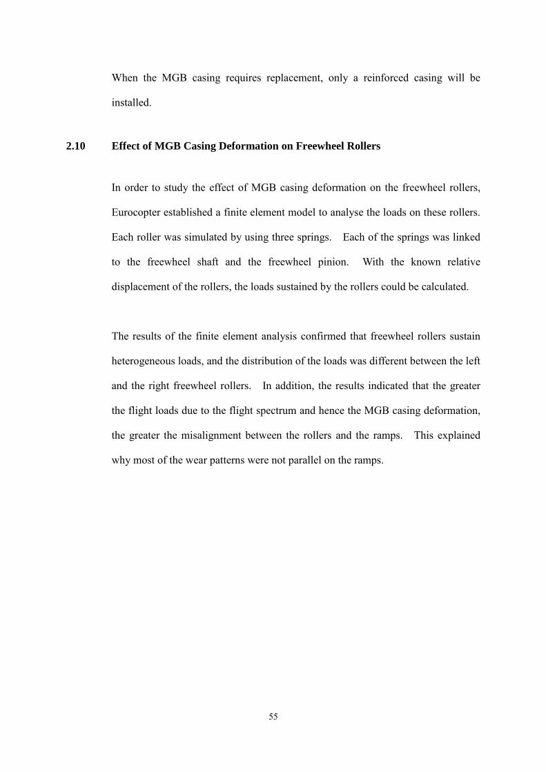
In order to study the effect of MGB casing deformation on the freewheel rollers,
Eurocopter established a finite element model to analyse the loads on these rollers.
Each roller was simulated by using three springs. Each of the springs was linked
to the freewheel shaft and the freewheel pinion. With the known relative
displacement of the rollers, the loads sustained by the rollers could be calculated.
The results of the finite element analysis confirmed that freewheel rollers sustain
heterogeneous loads, and the distribution of the loads was different between the left
and the right freewheel rollers. In addition, the results indicated that the greater
the flight loads due to the flight spectrum and hence the MGB casing deformation,
the greater the misalignment between the rollers and the ramps. This explained
why most of the wear patterns were not parallel on the ramps.
55
Vertical arrows indicate the load distribution on the rollers. (Courtesy of Eurocopter)
Figure 22 Analysis of Loads on Rollers with Finite Element Model
2.11 Effect of Power Level on Position of Freewheel Roller on Ramp
The position of a roller riding on a ramp depends on the level of power transmitted
through the freewheel unit. The higher the power, the higher the position of a
roller on a ramp. It should be noted that when the helicopter is used for
operations involving frequent torque variation, such as carrying water bucket for
firefighting in the accident flight, there were significant roller movement on the
ramp surfaces. The figure below shows a typical wear mark and its areas
corresponding to the levels of power.
56

(Courtesy of Eurocopter)
Figure 23 Roller Positions on Ramp Corresponding to Levels of Power
2.12 Evolution of Ramp Wear
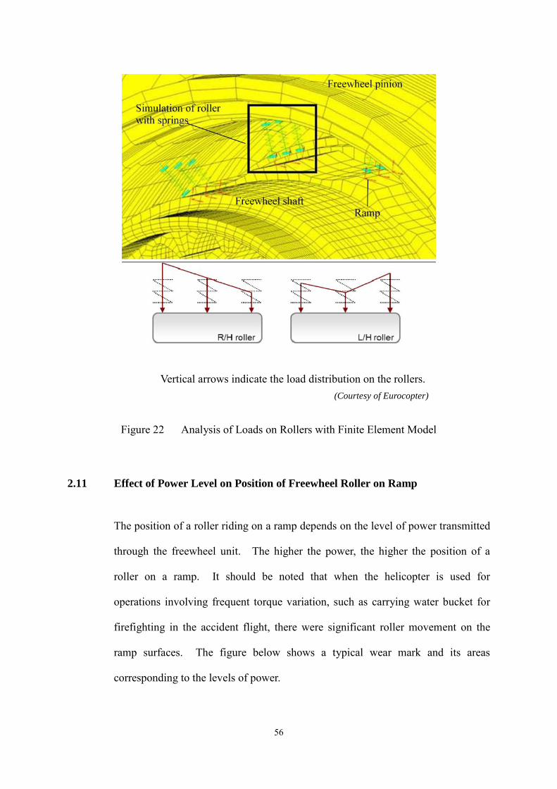
2.12.1 Ramp Wear Growth and Flight Loads
Figure 24 shows a schematic of micro-displacement of ramp rollers and the
evolution of ramp wear. The roller misalignment and the heterogeneous loads on
the rollers are the results of deformation of MGB casing under flight loads, and the
rollers would have micro-displacement on the ramps during the flight operations.
It has been mentioned earlier that the level of ramp wear depends on the number of
flight hours and the flight spectrum (flight loads and torque variation cycles).
Therefore, it can be understood that when the helicopter was used for firefighting
operations and there were repeated cyclical rubbing between the rollers and the
ramp surfaces, the amount of wear with each ramp surface increased over a period
of time and at a higher rate.
57
(Courtesy of Eurocopter)
Figure 24 Micro-displacement of Ramp Rollers and Evolution of Wear
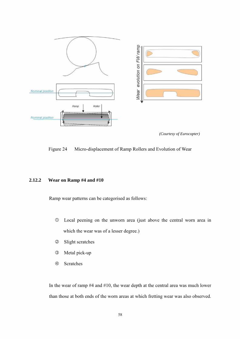
2.12.2 Wear on Ramp #4 and #10
Ramp wear patterns can be categorised as follows:
Local peening on the unworn area (just above the central worn area in
which the wear was of a lesser degree.)
Slight scratches
Metal pick-up
Scratches
In the wear of ramp #4 and #10, the wear depth at the central area was much lower
than those at both ends of the worn areas at which fretting wear was also observed.
58
On these “low-wear” areas, circumferential scratches were observed indicating that
the rollers had slipped on these areas.
(Courtesy of Eurocopter)
Figure 25 Wear Analysis on Ramp #4 and #10
It was highly probable that the shiny wear marks in the above photos were created
by the displacement of the rollers just before the freewheel slippage happened.
Firstly, the rollers climbed on the non-worn area (area ) due to maximum power
required to lift up water load, and the roller displacement induced local peening.
Then the rollers slid on the upper edge of the worn area due to displacement of
rollers. This roller displacement caused slight scratches at area . After that,
the rollers slid from the unworn area to the worn area and failed to re-engage.
The rollers then continued to slide downward and backward creating metal pick-up
at area and scratches at area .
59
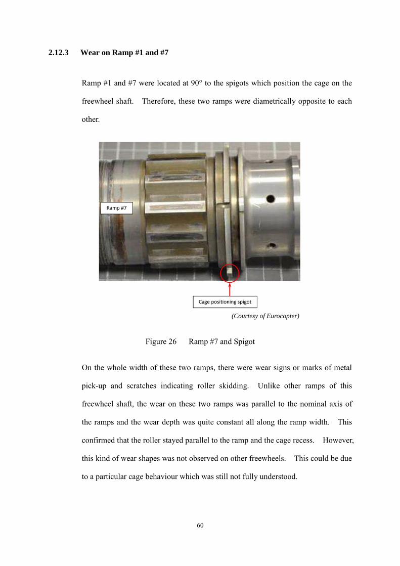
2.12.3 Wear on Ramp #1 and #7
Ramp #1 and #7 were located at 90° to the spigots which position the cage on the
freewheel shaft. Therefore, these two ramps were diametrically opposite to each
other.
(Courtesy of Eurocopter)
Figure 26 Ramp #7 and Spigot
On the whole width of these two ramps, there were wear signs or marks of metal
pick-up and scratches indicating roller skidding. Unlike other ramps of this
freewheel shaft, the wear on these two ramps was parallel to the nominal axis of
the ramps and the wear depth was quite constant all along the ramp width. This
confirmed that the roller stayed parallel to the ramp and the cage recess. However,
this kind of wear shapes was not observed on other freewheels. This could be due
to a particular cage behaviour which was still not fully understood.
60
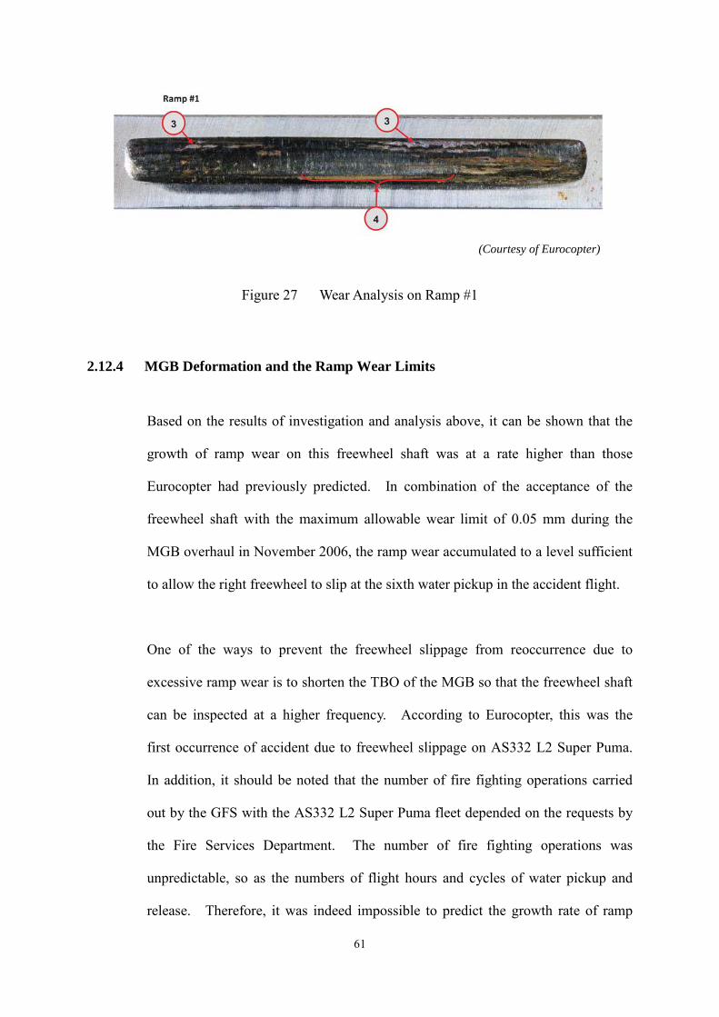
(Courtesy of Eurocopter)
Figure 27 Wear Analysis on Ramp #1
2.12.4 MGB Deformation and the Ramp Wear Limits
Based on the results of investigation and analysis above, it can be shown that the
growth of ramp wear on this freewheel shaft was at a rate higher than those
Eurocopter had previously predicted. In combination of the acceptance of the
freewheel shaft with the maximum allowable wear limit of 0.05 mm during the
MGB overhaul in November 2006, the ramp wear accumulated to a level sufficient
to allow the right freewheel to slip at the sixth water pickup in the accident flight.
One of the ways to prevent the freewheel slippage from reoccurrence due to
excessive ramp wear is to shorten the TBO of the MGB so that the freewheel shaft
can be inspected at a higher frequency. According to Eurocopter, this was the
first occurrence of accident due to freewheel slippage on AS332 L2 Super Puma.
In addition, it should be noted that the number of fire fighting operations carried
out by the GFS with the AS332 L2 Super Puma fleet depended on the requests by
the Fire Services Department. The number of fire fighting operations was
unpredictable, so as the numbers of flight hours and cycles of water pickup and
release. Therefore, it was indeed impossible to predict the growth rate of ramp
61
wear with the fire fighting operations. If the growth rate of ramp wear cannot be
predicted, it may not be possible to establish a new TBO in order to prevent the
possible freewheel slippage before it happens. Moreover, shortening of the TBO
of the MGB in consideration of the fire fighting operations will penalise the
operators providing passenger carrying services with AS332 L2 Super Puma.
In this accident, the freewheel slippage was caused by mainly the unpredicted high
growth rate of ramp wear due to MGB deformation and its associated effects on the
freewheel rollers, in combination of the maximum allowable wear limit of 0.05
mm for the acceptance of the freewheel shaft during the previous MGB overhaul.
It is considered that if appropriate corrective actions can be taken against the MGB
deformation and the wear acceptance limit of the freewheel shaft respectively, the
prevention of freewheel slippage from reoccurrence can still be effectively
achieved.
The investigation led to an understanding that if the non-reinforced MGB casing
would be modified so as to reduce the deformation, in particular during heavy load
lifting operations, the misalignment between the rollers and the ramps could be
reduced. This would allow more uniform contact and load between the mating
surfaces, and hence more even ramp wear pattern on the ramps. Consequently,
the ramp wear would grow at a rate comparable to those of passenger carrying
operations. In other words, it would not be necessary to establish different wear
limits for different operators which could be confusing to them. Therefore, the
same control measure of determining the period of overhaul and limits of the ramp
wear based on the traditional hours and cycles can still be applied effectively to
MGB operated for heavy load lifting and passenger carrying services.
62
On the other hand, AS332 L2 Super Puma helicopter operating with right
freewheel shaft previously accepted with the 0.05 mm maximum wear limit will be
of a higher risk of ramp wear closer to the limits, but the risk will not be significant
unless they have a non-reinforced MGB casing and also frequently engaged in
heavy load lifting operations.
2.13 Actions Already Taken by Eurocopter
2.13.1 Freewheel Shaft Ramp Wear Limit
In 2007, Eurocopter issued Letter to Repair Stations LR No.214 to tighten the
maximum ramp wear depth limit from 0.05 mm to 0.005mm. In other words,
only MGB overhauled after LR No.214 came into effect would benefit from the
tightened wear limit.
2.13.2 Freewheel Shaft and Ball Bearing Replacement during MGB Overhaul
As a result of this accident, Eurocopter also issued Letter to Repair Stations LR
No.248 to mandate the installation of a new shaft and a new cage in the right
freewheel unit, and the replacement with new ball bearings for both left and right
freewheel shafts when an MGB is under a Complete Overhaul every 3,000 flight
hours. In other words, even a right freewheel shaft is accepted with the maximum
ramp wear depth limit of 0.005 mm, it will only be re-used in the left freewheel
unit.
63
2.13.3 Redesign of Freewheel Shaft
Eurocopter advised that a new freewheel unit was under design. The new design
would be available for installation in new MGB and MGB under overhaul.
2.13.4 MGB Modification
Eurocopter modification 07 52472 (Reinforced casing for 332 MK2 MGB) was
available for the reinforcement of the MGB casing before the accident happened;
however, it was only an optional modification.
64

3
3.1.1
CONCLUSIONS
3.1 Findings
3.1.2
3.1.3
3.1.4
3.1.5
3.1.6
3.1.7
3.1.8
The flight crew were properly licensed, trained and qualified to
conduct the flight and were well rested.
The helicopter was certified, equipped and maintained in accordance
with existing Hong Kong airworthiness regulations.
The mass and the centre of gravity of the aircraft were within the
prescribed limits.
The maintenance records indicated that the aircraft was maintained
in compliance with the approved maintenance schedule.
The visibility of the flight was 10 km or more and there was no
significant weather.
When the accident occurred, the helicopter was on its sixth water
pickup with the bucket filled, just lifted clear of the water surface
and rotated to gain forward speed at 129 ft above the water surface.
No.2 engine shut down due to the automatic protection from free
turbine overspeed.
The captain decided to ditch the helicopter and it ditched in a
controlled manner and was intact. It was then kept afloat by the
four emergency floats.
Before ditching, a “MAYDAY” call was transmitted by the co-pilot
which was acknowledged by Air Traffic Control (ATC) Tower at
Hong Kong International Airport.
65
3.1.9
3.1.10 All three crew members were unharmed and they managed to swim
ashore before the rescue fire fighters arrived.
3.1.11 There were no known defects or malfunction in the aircraft systems
which could have contributed to the accident.
3.1.12 The overspeed of the No.2 engine free turbine speed NF was the
result of the No.2 freewheel unit slippage.
3.1.13 The modification standard of the MGB was before the Eurocopter
modification 07 52472 (Reinforced casing for 332 MK2 MGB)
which was introduced on 19 October 2001 to reinforce the MGB
casing at the right freewheel area and reduce the deformation of the
casing in operations.
3.1.14 When the MGB was previously overhauled in 2006, the right
freewheel shaft was accepted to remain in service while the ramp
wear limit at the time was 0.05 mm.
3.1.15 HUMS did not record any anomalies related to the freewheel units
as it was not designed to detect degradation in the units.
3.1.16 The SSCVFDR was fitted in accordance with regulatory
requirements.
3.1.17 The spectral analysis on the cockpit ambient sound recording
together with the SSCVFDR data confirmed that overspeed of the
power turbine of No.2 engine occurred in flight.
3.1.18 The ramp wear on the freewheel shaft grew at a rate higher than
what Eurocopter had predicted in the maintenance programme.
66
3.1.19 Computational analysis showed that the level of MGB casing
deformation is significantly higher in the area of the right freewheel
unit.
3.1.20 The finite element analysis on the loads on the freewheel rollers
confirmed that freewheel rollers sustain heterogeneous loads, and
the distribution of the loads was different between the left and the
right freewheel rollers. In addition, the results indicated that the
greater the flight loads due to the flight spectrum and hence the
MGB casing deformation, the greater the misalignment between the
rollers and the ramps.
3.1.21 The roller misalignment and the heterogeneous loads on the rollers
are the results of deformation of MGB casing under flight loads, and
the rollers would have micro-displacement on the ramps during the
flight operations.
3.1.22 When the helicopter was used for fire fighting operations, the ramp
wear grew at a higher rate than passenger carrying operations.
3.1.23 The freewheel slippage was caused by mainly the unpredicted high
growth rate of ramp wear due to MGB deformation and its
associated effects on the freewheel rollers, in combination of the
maximum allowable wear limit of 0.05 mm for the acceptance of the
freewheel shaft during the previous MGB overhaul.
3.2 Causes
3.2.1 Casual factor
The investigation identified the following causal factors. Numbers in parenthesis
refer to the relevant paragraph number in Sections 2 and 3 of this Report.
67
3.2.1.1 The automatic shutdown of No.2 engine was due to free turbine
overspeed as the result of a slippage of the right freewheel shaft in the
MGB. (2.4, 3.1.7, 3.1.12, 3.1.17)
3.2.1.2 The right freewheel unit slipped because of the unpredicted growth
rate of ramp wear and the maximum allowable wear limit of 0.05 mm
for the acceptance of the freewheel shaft during the previous MGB
overhaul. (2.12.4, 3.1.23)
3.2.1.3 Due to the deformation of MGB under flight loads and the associated
effects on the freewheel rollers, during fire fighting operations the
ramp wear grew at a higher rate than those Eurocopter had predicted.
(2.8, 2.9, 2.10, 2.11, 2.12, 3.1.18. 3.1.21, 3.1.22)
68
4 SAFETY RECOMMENDATIONS
4.1 Recommendation
Based on the findings, causal factors and actions already taken by Eurocopter, the
investigation team has made one safety recommendation.
4.1.1 Recommendation 2013 -1
It is recommended that the European Aviation Safety Agency (EASA) mandate the
installation of an MGB modified in accordance with Eurocopter modification 07
52472 (Reinforced casing for 332 MK2 MGB) on AS332 L2 Super Puma which
are operated for carriage of heavy loads with torque variation cycles. (3.2.1.3)
69
1
2
3
4
5
6
APPENDICES
Appendix Freewheel unit schematic and cross section
Appendix Flight Manual Supplement 5 Figure 1
Appendix Plot of Flight Data (the Last 33 Minutes)
Appendix Plot of Flight Data (The Last Three Minutes)
Appendix Spectral Analysis of Cockpit Area Microphone Recording
Appendix Wear Patterns on the Ramp of the Right Freewheel Shaft
70
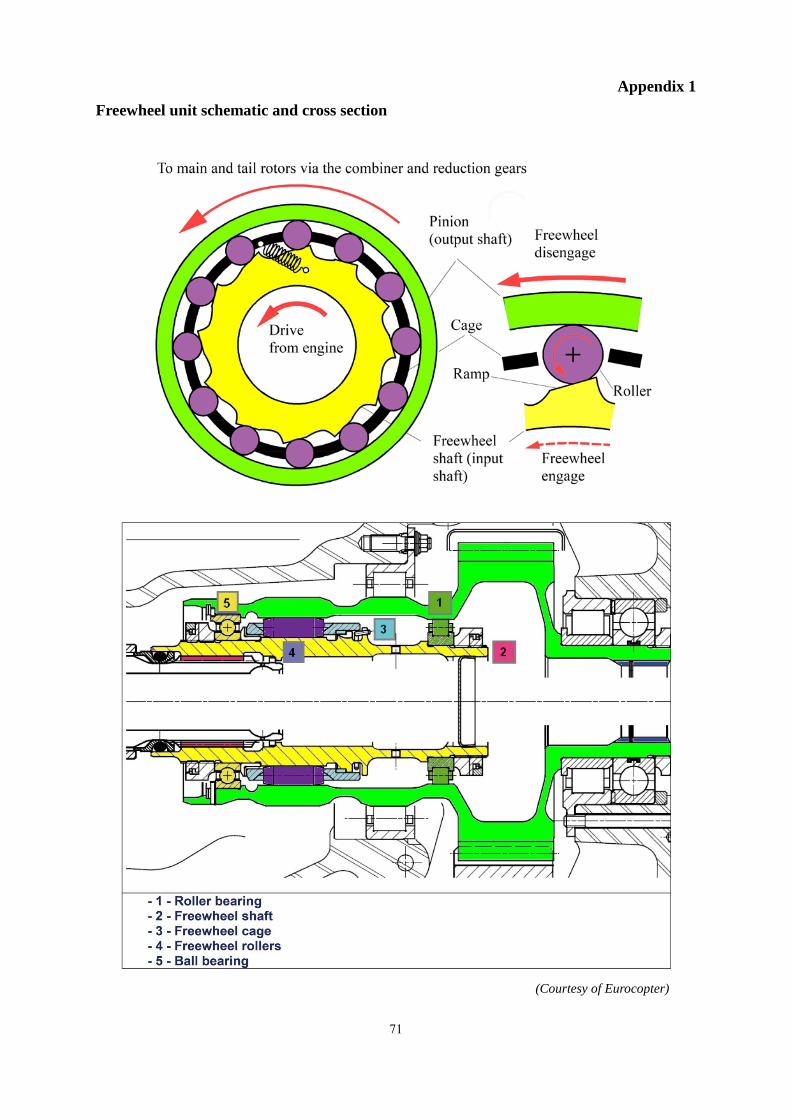
Appendix 1 Freewheel unit schematic and cross section
(Courtesy of Eurocopter)
71
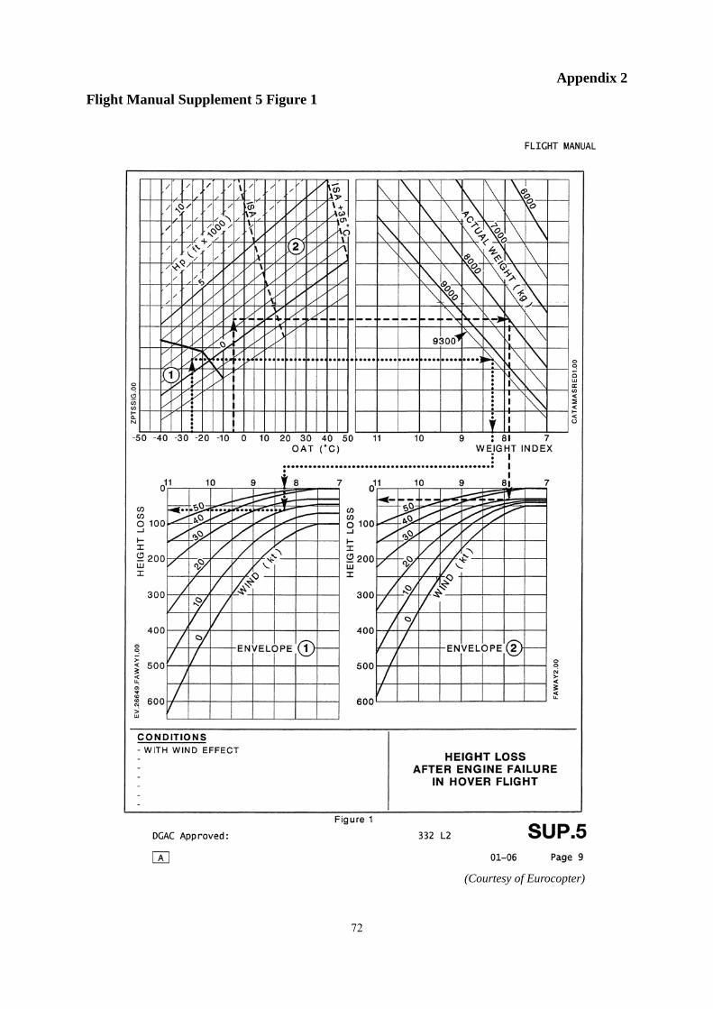
Appendix 2
Flight Manual Supplement 5 Figure 1
(Courtesy of Eurocopter)
72
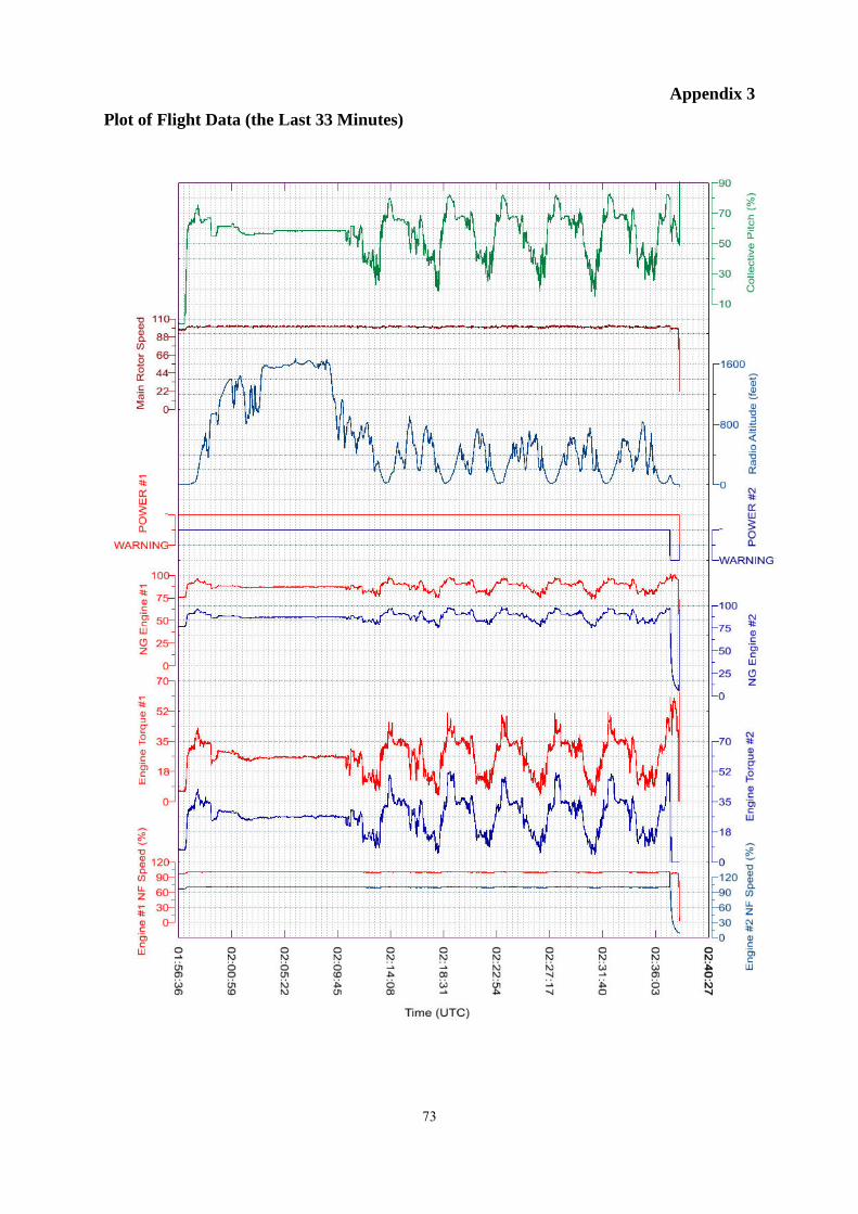
Appendix 3 Plot of Flight Data (the Last 33 Minutes)
73
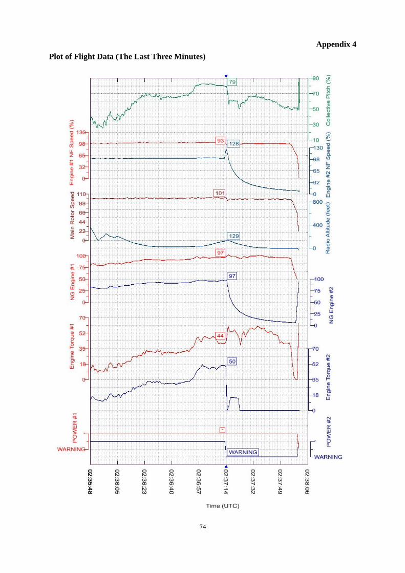
Appendix 4 Plot of Flight Data (The Last Three Minutes)
74

Appendix 5 Spectral Analysis of Cockpit Area Microphone Recording
A thud is heard at time 3731.24 seconds (duration 160 to 200 milliseconds). It was followed by the increase in frequency of the NL (speed of the free turbine at the MGB entrance). At time 3731.6 seconds while the NL reached the value of 121%, the NG suddenly decreased as for an engine shutdown. The NL max value observed in the spectral analysis was 132% (see below).
75
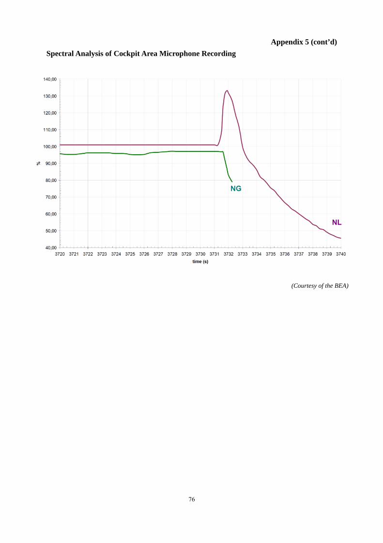
Appendix 5 (cont’d) Spectral Analysis of Cockpit Area Microphone Recording
(Courtesy of the BEA)
76
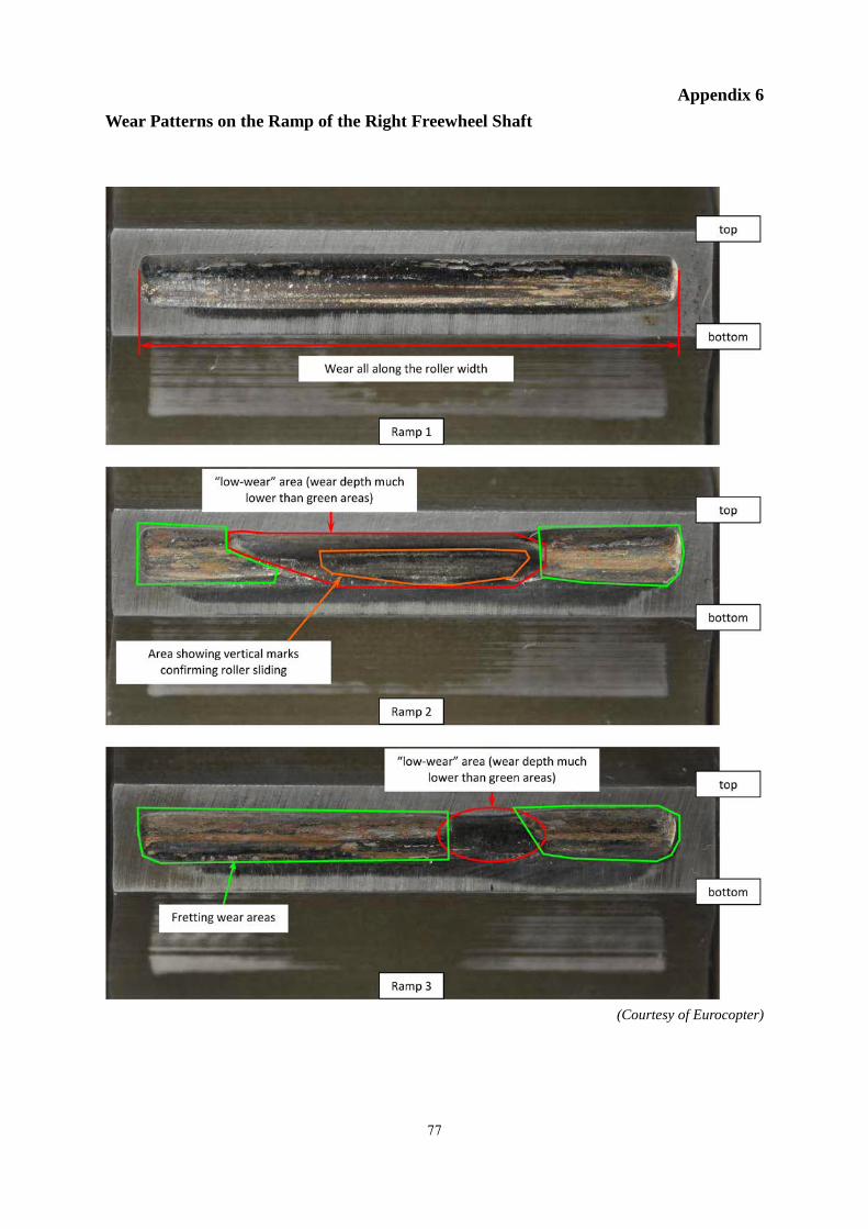
Appendix 6 Wear Patterns on the Ramp of the Right Freewheel Shaft
(Courtesy of Eurocopter)
77
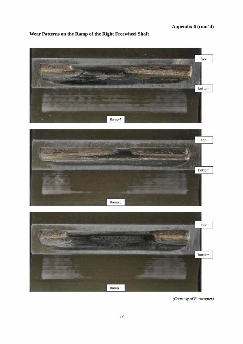
Appendix 6 (cont’d) Wear Patterns on the Ramp of the Right Freewheel Shaft
(Courtesy of Eurocopter)
78
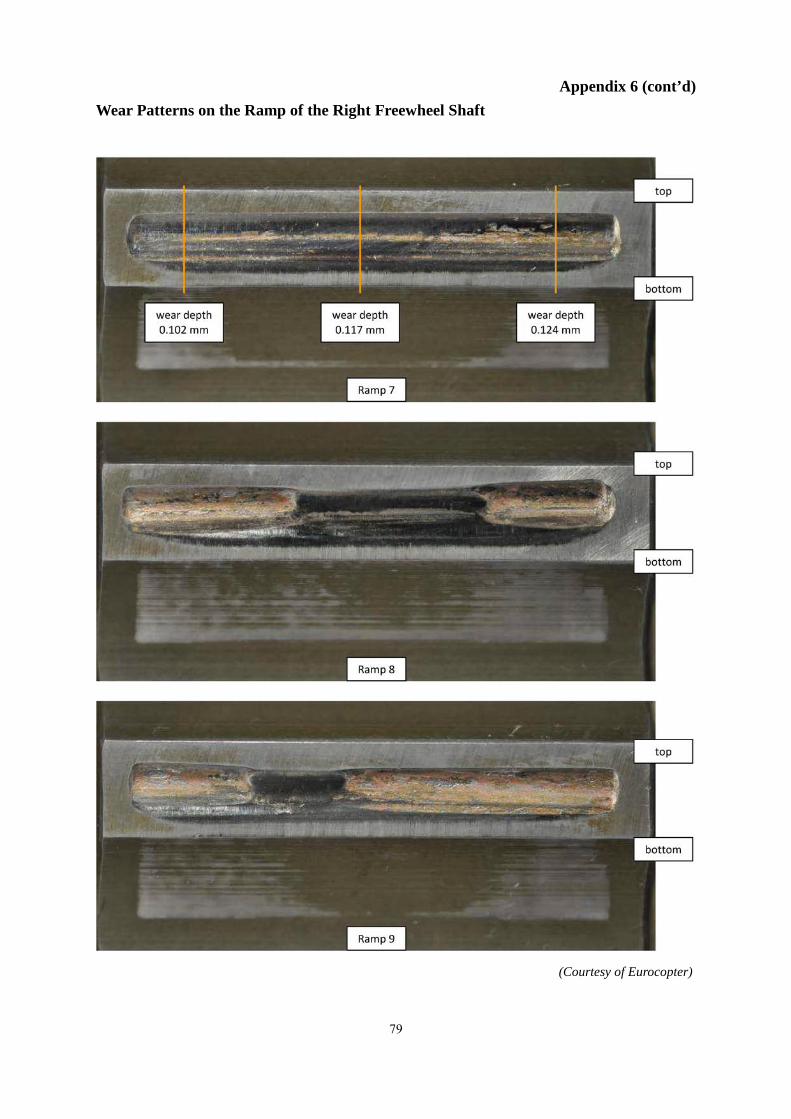
Appendix 6 (cont’d) Wear Patterns on the Ramp of the Right Freewheel Shaft
(Courtesy of Eurocopter)
79
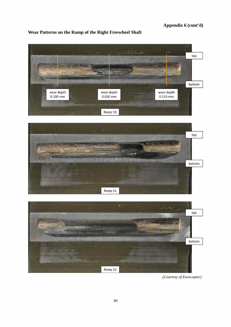
Appendix 6 (cont’d) Wear Patterns on the Ramp of the Right Freewheel Shaft
(Courtesy of Eurocopter)
80