
Airbus_28_A300_A310_Fuel
74
MTT M540000/R3.4 16AUG01 MTT M540000/R3.4 16AUG01 For Training Purposes Only For Training Purposes Only ATA 28 ATA 28 A300/A310 A300/A310 28- 28-1 ATA 28 ATA 28 Fuel Fuel
-
Upload
elijah-paul-merto -
Category
Documents
-
view
13 -
download
3
description
Airbus A300/A310 ATA 28 Training Manual. Contains the operation of the Fuel System.
Transcript of Airbus_28_A300_A310_Fuel

MTT M540000/R3.4 16AUG01MTT M540000/R3.4 16AUG01For Training Purposes OnlyFor Training Purposes Only
ATA 28ATA 28A300/A310A300/A310
28-28-11
ATA 28ATA 28FuelFuel

MTT M540000/R3.4 16AUG01MTT M540000/R3.4 16AUG01For Training Purposes OnlyFor Training Purposes Only
ATA 28ATA 28A300/A310A300/A310
28-28-22
A300/A310 Fuel System
GENERAL DESCRIPTION
The Fuel System includes six tanks with two (2) fuel pumps each, theVent System, Fuel Quantity Indicating System (FQIS), Refuel/DefuelSystem, and the associated Fuel System Controls and Indicators. Thefuel is stored in integral wing tanks, in a Center Tank located in the WingCenter Box, and in a Trim Tank (A300 Only) located in the HorizontalStabilizer Assembly.
Normally the wing tanks supply the engine on their respective side, buteach engine and the APU can crossfeed from any Wing or Center Tank.APU fuel is provided from the LH side of the Crossfeed Line.
The fuel feed sequence is automatic. Negative acceleration has noadverse effect on fuel supply. To shut off the fuel supply to the enginesand APU, three electrically controlled Fuel Fire Shutoff Valves are
provided (One Per Engine and APU). Each individual tank is shut off byan electrically controlled Isolation Valve. Refueling and Defueling ispossible, if required, by Battery Number 1 power only. Fuel transferbetween Wing and Center Tanks is possible on the ground only.
When Outer Tank fuel is consumed, VMO is reduced (MaximumOperating Speed). The tanks contain adequate baffling to prevent unduefuel movement. For removal of water accumulation in the tanks, 10Water Drain Valves are provided: Two (2) in each Outer Tank and CenterTank, One (1) in each Inner Tank and Vent Tank (Surge Tank). Anadditional volume in each tank allows for a 2% thermal expansion of fuelwithout spillage. In the Center Tank, a Water Drain Scavenge Systemenables water to be drawn into the Main Engine Number 1 and 2 FfeedSystem and consumed.

MTT M540000/R3.4 16AUG01MTT M540000/R3.4 16AUG01For Training Purposes OnlyFor Training Purposes Only
ATA 28ATA 28A300/A310A300/A310
28-28-33
A300/A310 Fuel System - Tank Layout
A300-600R
A310-200

MTT M540000/R3.4 16AUG01MTT M540000/R3.4 16AUG01For Training Purposes OnlyFor Training Purposes Only
ATA 28ATA 28A300/A310A300/A310
28-28-44
Engine and APU Fuel Feed
DESCRIPTION
Each tank is equipped with two fuel pumps. Each Outer Tank is providedwith an Isolation Valve which connects it to the Main Engine Fuel FeedManifold. An Isolation Valve connects the LH Inner tank pumps and theCenter Tank LH Pump to the LH side of the manifold, another oneconnects the RH Inner Tank Pumps and the Center RH Tank Pump tothe RH side of the manifold. The Isolation Valves are electricallyoperated and manually controlled.
The Crossfeed Line and the Crossfeed Valve interconnect the left andthe right side of the Crossfeed Manifold. The Crossfeed Valve iselectrically operated simultaneously by two motors. Each engine is fedfrom the respective side of the manifold. Pump activation is controlled bythe automatic fuel feed sequence or by manual selection. The APU isfed from the left side of the Crossfeed Line. If the APU is started withouttank pumps available, the APU LP (Low Pressure) Fuel Boost Pump willoperate. The pump is automatically activated when the fuel supplypressure is below 22 PSI (17.5 PSI). By selecting the Crossfeed ValveOPEN, an engine can be fed from the opposite side of the Main EngineFuel Manifold and the APU from the right side of the Crossfeed Line.
In case of a fire, the fuel supply to the Engine(s) 1 / 2 or the APU is shutoff by the LP Valves Fire Shutoff Valves) which are electrically operatedby two motors (One only in the case of APU), when the related ENGFIRE or APU FIRE handle is pulled. The Inner and Center Tank Pumpscannot run at the same time. The tank pumps are controlled by the INR,CTR and OUTR TK PUMP switches on the FUEL Panel 430VU sectionof the Overhead Panel in the Flight Compartment, which also permitsselection of the Automatic Feed Mode (Center and Inner Tanks Only).
AUTOMATIC FEED MODE SELECTION
The Outer Tank Pumps are not connected by the Automatic Feed Mode.The Automatic Feed Mode is selected, provided at least one pump ineach Inner and Center Tank is selected NORM.
It will be deselected if any of the four pumps (Two Pumps per Tank) inthe LH/RH Inner Tanks or the two pumps (LH/RH Center Tank Pumps) inthe Center Tank are selected OFF, or if the MODE SELECTOR on theREFUEL/DEFUEL Panel 110VU (A300/Some A310) orREFUELL/DEFUEL Panel on the Maintenance Panel (A310 Only) isselected REFUEL. Fuel Feed Mode is then MANUAL and all the pumpsare then directly controlled from their respective Pushbutton Switch(PBsw).
AUTOMATIC FEED MODE SEQUENCE
At engine start, if CTR TK is not empty, CTR TK will feed. 3 minutes laterthe Inner Tank Pumps feed. After takeoff, at Leading Edge Slatretraction, CTR TK feeds again until it is empty (A300/A310). If fuel iscarried in the Trimmable Horizontal Stabilizer (THS), the Fuel FeedSequence operates in a different mode.
NOTE: In the case of landing with fuel in the Center Tank, feeding willtransfer to Inner Tanks three (3) minutes after touchdown, until engineshut down.

MTT M540000/R3.4 16AUG01MTT M540000/R3.4 16AUG01For Training Purposes OnlyFor Training Purposes Only
ATA 28ATA 28A300/A310A300/A310
28-28-55
A300/A310 Fuel System - Schematics
MTT M540000/R3.4 16AUG01MTT M540000/R3.4 16AUG01For Training Purposes OnlyFor Training Purposes Only
ATA 28ATA 28A300/A310A300/A310
28-28-66
Fuel Transfer System
Two pumps in each Wing and Center Tank supply fuel to the MainEngines 1 and 2. The pumps supply fuel at the necessary pressure andflow rate through Wing Tank Isolation Valves and Low Pressure V (FireShutoff Valves). If the Crossfeed Valve is OPENED, fuel supplied toMain Engine 1 or 2, or both Main Engines 1 and 2 from any Main Tank(Center, Inner or Outer Tanks). During this mode of operation, fuel canbe quantities can be controlled to control fuel balance between the Leftand Right Wings.
A Fuel Transfer System automatically supplies fuel to the Center Tankfrom the Trim Tank (A300 Only), or from the Center or Inner Tank(s) tothe Trim Tank (A300 Only), through a double walled flexible hose andstainless steel rigid pipe housed in an alloy shroud. This system controlsthe Aircraft Center of Gravity (CG) during flight conditions . TheAutomatic Transfer is overridden by the Trim Tank Isolation ValveSystem (A300 Only). Under certain flight conditions, transfer may bemanually overridden at any time.

MTT M540000/R3.4 16AUG01MTT M540000/R3.4 16AUG01For Training Purposes OnlyFor Training Purposes Only
ATA 28ATA 28A300/A310A300/A310
28-28-77
A300/A310 Fuel System - Schematics

MTT M540000/R3.4 16AUG01MTT M540000/R3.4 16AUG01For Training Purposes OnlyFor Training Purposes Only
ATA 28ATA 28A300/A310A300/A310
28-28-88
A300 FUEL Panel 430 VU
OPERATION
1. ENG 1, APU and ENG 2 LP VALVE ANNUNCIATORSThe position of the LP valves in the fuel feed lines to both enginesand the APU is displayed. The valves close only when the respectiveFIRE handle is pulled.• In line
Flowbar comes on Green, SHUT light is off. The valve is open.• SHUT
SHUT light comes on Amber, the flowbar is off. The valve isclosed.
2. X FEED FLOWBAR, PUSHBUTTON SWITCHThe P/B switch controls the operation of the fuel cross feed valve.• Released-out
The flowbar comes on Green and crosses the system synoptic.The valve is closed.
• Pressed-InThe flowbar comes on Green and is in line. The valve is open.The indication "FUEL X FEED" is given on the SCAM MEMOpage.
3. ISOL VALVES PUSHBUTTON SWITCHESAll four P/B switches are guarded. They control the position of therelated tankisolation valve in the fuel feed line. The inner tank isolation valvesshut off the fuel supply from the respective center tank pump as well.• P/B switch pressed-in
The valve is opened. The flowbar comes on Green, in line.• P/B switch released-out
The valve is closed. The OFF light comes on White. The flowbaris off.
• Flowbar flashingThe valve position disagrees with the P/B switch setting.
4. OUTR TK/PUMP 1 AND 2 PUSHBUTTON SWITCHESControl tank pumps in outer tanks.• ON (P/B switch pressed-in)
Pump is in operation, but fuel is only fed when delivery pressurefrom inner or center tank pumps drop below threshold.
• OFF (P/B switch released-out)Pump is deactivated, the OFF light comes on White.
• LO PRThe light comes on Amber when the delivery pressure drops due topump failure or fuel starvation. The LO PR light is inhibited when thepump is switched OFF. Illumination of the LO PR light activates theECAM system.

MTT M540000/R3.4 16AUG01MTT M540000/R3.4 16AUG01For Training Purposes OnlyFor Training Purposes Only
ATA 28ATA 28A300/A310A300/A310
28-28-99
A300 FUEL Panel 430 VU
1
2
3
4

MTT M540000/R3.4 16AUG01MTT M540000/R3.4 16AUG01For Training Purposes OnlyFor Training Purposes Only
ATA 28ATA 28A300/A310A300/A310
28-28-1010
A300 FUEL Panel (Continued)
5. INR TK/PUMP AND CTR TK/PUMP PUSHBUTTON SWITCHES.The 3 pair of pushbuttons permit the selection of the feed mode logic.- if one pump at least in each tank is selected NORM, the automatic
feed mode is selected.- if the four pumps in the INR tanks or the two pumps in the CTR
tank are selected OFF, the automatic feed mode is deselected.• Norm (P/B switch pressed in)
Pump operation depends on FEED MODE- AUTO: pump is activated according to feed mode logic.- MAN: pump is directly activated.
• OFF (P/B switch released out)Pump is not activated. The White light is ON.
• FAULTThe light comes on Amber, associated with ECAM.- as a single warning, when the delivery pressure drops. This
indicates a pump failure or fuel starvation.- associated with all the other inner (or center) tank pump
FAULT lights in case of automatic feed mode failure. TheFAULT light is inhibited when the switch is selected OFF.
NOTE:1. When one of the two CTR TANK pumps is running, the indication
"CTR TANK FEEDING" is given on the ECAM MEMO page.2. Switching from CTR to INR tanks feeding may occur prematurely
during climb, due to pitch angle.

MTT M540000/R3.4 16AUG01MTT M540000/R3.4 16AUG01For Training Purposes OnlyFor Training Purposes Only
ATA 28ATA 28A300/A310A300/A310
28-28-1111
A300 FUEL Panel 430 VU
5 5

MTT M540000/R3.4 16AUG01MTT M540000/R3.4 16AUG01For Training Purposes OnlyFor Training Purposes Only
ATA 28ATA 28A300/A310A300/A310
28-28-1212
A300/A310 FUEL Panel 430 VU
MTT M540000/R3.4 16AUG01MTT M540000/R3.4 16AUG01For Training Purposes OnlyFor Training Purposes Only
ATA 28ATA 28A300/A310A300/A310
28-28-1313
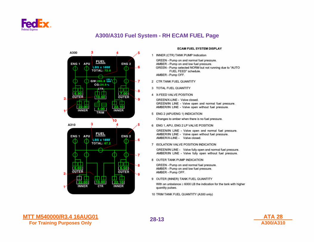
A300/A310 Fuel System - RH ECAM FUEL Page
MTT M540000/R3.4 16AUG01MTT M540000/R3.4 16AUG01For Training Purposes OnlyFor Training Purposes Only
ATA 28ATA 28A300/A310A300/A310
28-28-1414
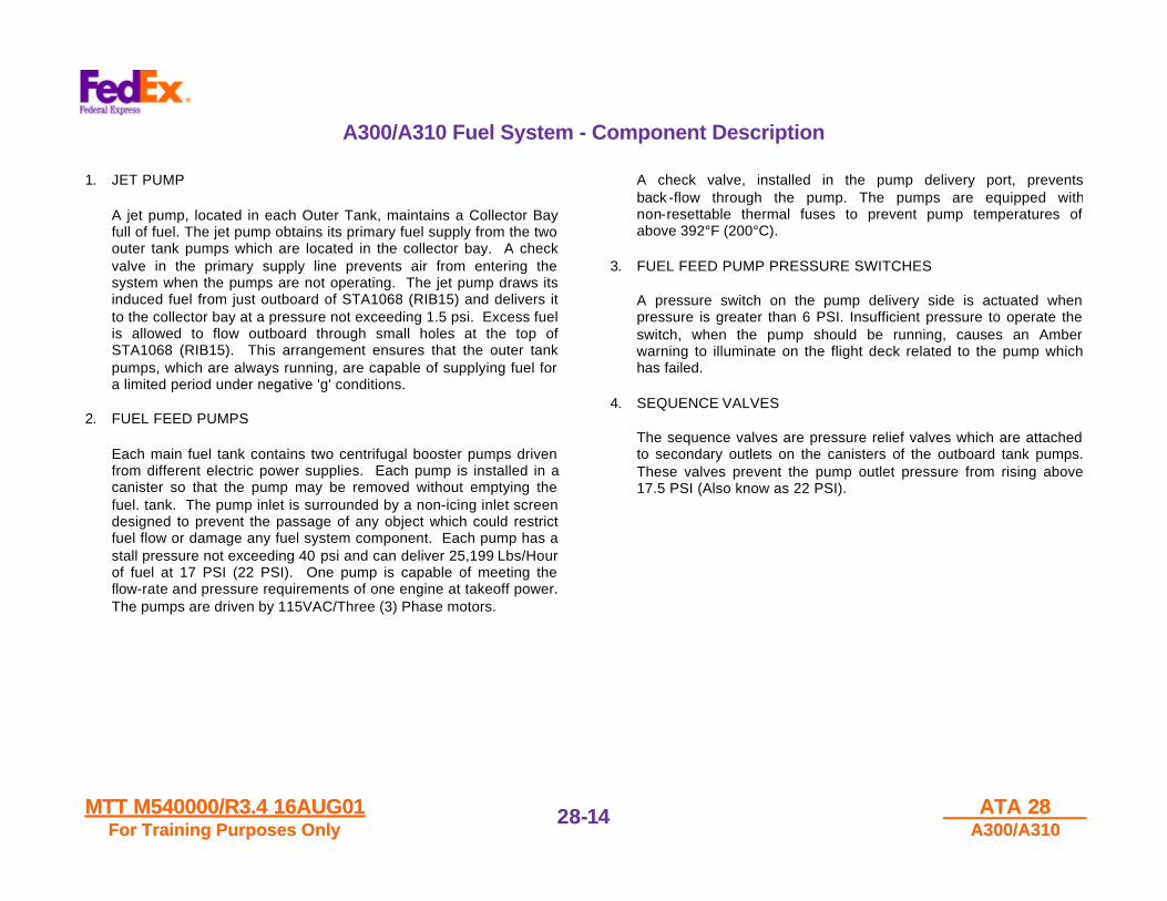
A300/A310 Fuel System - Component Description
1. JET PUMP
A jet pump, located in each Outer Tank, maintains a Collector Bayfull of fuel. The jet pump obtains its primary fuel supply from the twoouter tank pumps which are located in the collector bay. A checkvalve in the primary supply line prevents air from entering thesystem when the pumps are not operating. The jet pump draws itsinduced fuel from just outboard of STA1068 (RIB15) and delivers itto the collector bay at a pressure not exceeding 1.5 psi. Excess fuelis allowed to flow outboard through small holes at the top ofSTA1068 (RIB15). This arrangement ensures that the outer tankpumps, which are always running, are capable of supplying fuel fora limited period under negative 'g' conditions.
2. FUEL FEED PUMPS
Each main fuel tank contains two centrifugal booster pumps drivenfrom different electric power supplies. Each pump is installed in acanister so that the pump may be removed without emptying thefuel. tank. The pump inlet is surrounded by a non-icing inlet screendesigned to prevent the passage of any object which could restrictfuel flow or damage any fuel system component. Each pump has astall pressure not exceeding 40 psi and can deliver 25,199 Lbs/Hourof fuel at 17 PSI (22 PSI). One pump is capable of meeting theflow-rate and pressure requirements of one engine at takeoff power.The pumps are driven by 115VAC/Three (3) Phase motors.
A check valve, installed in the pump delivery port, preventsback -flow through the pump. The pumps are equipped withnon-resettable thermal fuses to prevent pump temperatures ofabove 392°F (200°C).
3. FUEL FEED PUMP PRESSURE SWITCHES
A pressure switch on the pump delivery side is actuated whenpressure is greater than 6 PSI. Insufficient pressure to operate theswitch, when the pump should be running, causes an Amberwarning to illuminate on the flight deck related to the pump whichhas failed.
4. SEQUENCE VALVES
The sequence valves are pressure relief valves which are attachedto secondary outlets on the canisters of the outboard tank pumps.These valves prevent the pump outlet pressure from rising above17.5 PSI (Also know as 22 PSI).
MTT M540000/R3.4 16AUG01MTT M540000/R3.4 16AUG01For Training Purposes OnlyFor Training Purposes Only
ATA 28ATA 28A300/A310A300/A310
28-28-1515
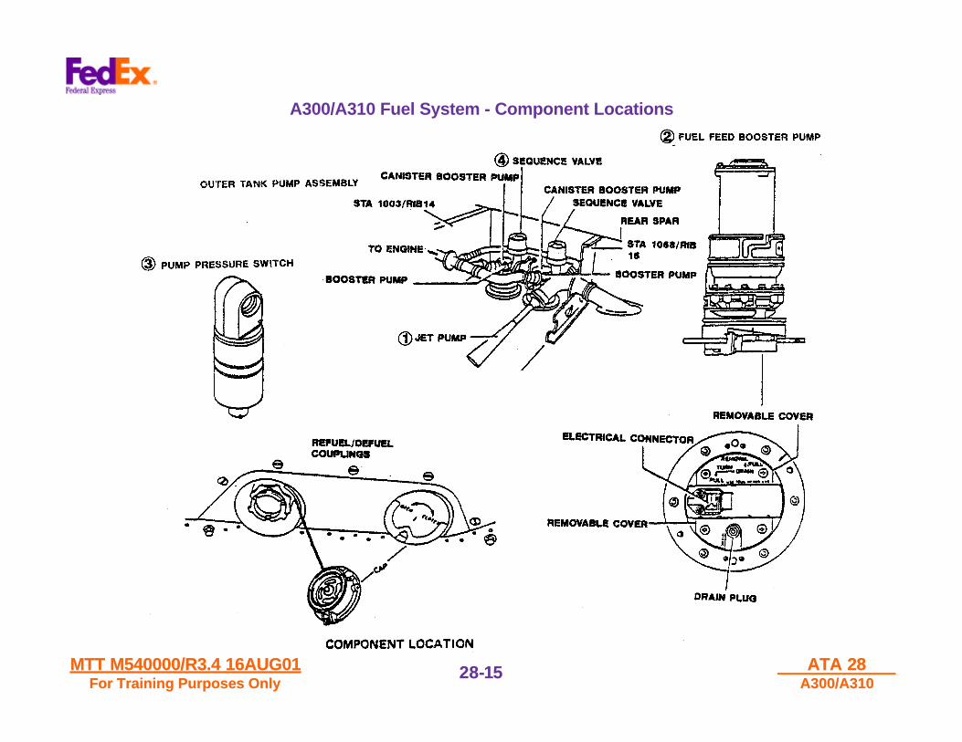
A300/A310 Fuel System - Component Locations
MTT M540000/R3.4 16AUG01MTT M540000/R3.4 16AUG01For Training Purposes OnlyFor Training Purposes Only
ATA 28ATA 28A300/A310A300/A310
28-28-1616
Fuel System Valves - Component Description
1. CROSSFEED VALVE
The valve, which is flange-mounted in the center tank on the rearspar, is an electrically-actuated spherical plug type and comprises abody with line attachments, spherical plug and control. spindle. Thecontrol spindle protrudes through the rear spar and the electricalactuator is mounted outside the tank.
2. LOW PRESSURE VALVE (LP VALVE)
The LP Valve (Fire Shutoff Valve), which is flange-mounted by theinlet port to an adapter on the front spar, is an electrically-actuatedspherical-plug type and comprises a cast body with line attachment,spherical plug and control spindle. The actuator comprises twoelectric motors driving a common gearbox to provide 90 degreespherical-plug travel. Microswitches stop the motors at the end oftravel and complete the position indication circuits. The motors drivethe reduction gear which allows either motor to drive the valve whenthe other is not electrically powered or is mechanically incapable ofrotating. Final drive is through a locking mechanism (Autoloc) whichdisengages the output shaft from the reduction gear when the motorsare signaled to stop by the limit switches.
3. ISOLATION VALVE
The Wing Tank Isolation Valves are electrically actuated,spherical-plug valves, of two inch diameter, and consist of a bodywith pipe attachments, a ball, and spindle. The wing tank isolationvalves flange mount to the inside of the tank rear; the spindlesprotrude through the tank walls, and the wing tank isolation valveelectrical actuators are mounted on the outside of the tank. The trimtank isolation valve is mounted inside the trim tank in the transfer fuelfeed line, close to the tank outlet, in the lower skin. The mounting ofthe valve and actuator is such that reactive loads are not transmittedto the fuel lines.

MTT M540000/R3.4 16AUG01MTT M540000/R3.4 16AUG01For Training Purposes OnlyFor Training Purposes Only
ATA 28ATA 28A300/A310A300/A310
28-28-1717
A300/A310 Fuel System - Component Location
MTT M540000/R3.4 16AUG01MTT M540000/R3.4 16AUG01For Training Purposes OnlyFor Training Purposes Only
ATA 28ATA 28A300/A310A300/A310
28-28-1818
Fuel Vent Surge Tank System
Description
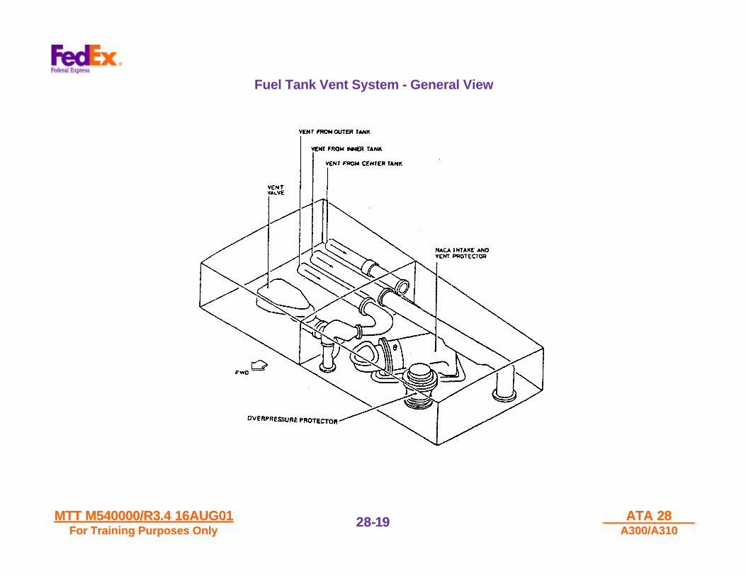
At the tip of each wing, a Vent Surge Tank is connected to theatmosphere by a flush NACA Intake (NACA is the abbreviation forNational Advisory Committee of Aeronautics – USA / up to Year 1958and now NASA (National Aeronautics and Space Administration) / USAsince Year-1958) and to the tanks by vent pipes. Each Inner (or Outer)Tank is connected to the Vent Surge Tank located in its respective wing.The Center Tank vents into the LH Wing Vent Tank.
The Vent System ensures positive pressure on the fuel in specific pitchand roll attitudes of the aircraft. It prevents tank overpressure duringrefueling. It takes the excess fuel, in case of a Refuel/Defuel Valvefailure or in case of high thermal expansion, to the Vent Surge Tankswhich serve as expansion chambers.
Fuel in the Vent Surge Tank is siphoned back and goes into itsassociated tanks when the engines demand fuel from these tanks. Fuelmay be vented overboard when the Vent Surge Tank is full. Asadditional overpressure protection each Inner Tank, Center Tank andVent Surge Tanks are provided with Overpressure Protectors consistingof carbon safety discs. The positioning of Overpressure Carbon SafetyDiscs ensures that the fuel loss is limited in the event of an overpressureconditions.
MTT M540000/R3.4 16AUG01MTT M540000/R3.4 16AUG01For Training Purposes OnlyFor Training Purposes Only
ATA 28ATA 28A300/A310A300/A310
28-28-1919
Fuel Tank Vent System - General View

MTT M540000/R3.4 16AUG01MTT M540000/R3.4 16AUG01For Training Purposes OnlyFor Training Purposes Only
ATA 28ATA 28A300/A310A300/A310
28-28-2020
Center and Inner Tanks - Warning Logic
Shown below are the different warnings that will occur in the Flight Compartmentin the event the fault shown occurs in the Center and Inner Tanks. Also depictedgraphically are the different Flight Phases at which the warnings will or will notoccur.

MTT M540000/R3.4 16AUG01MTT M540000/R3.4 16AUG01For Training Purposes OnlyFor Training Purposes Only
ATA 28ATA 28A300/A310A300/A310
28-28-2121
Center and Inner Tanks - Warning Logic

MTT M540000/R3.4 16AUG01MTT M540000/R3.4 16AUG01For Training Purposes OnlyFor Training Purposes Only
ATA 28ATA 28A300/A310A300/A310
28-28-2222
Fuel Quantity Indication System (FQIS)
DescriptionEach tank is equipped with several capacitance probes. In each tank oneprobe is fitted with a Capacity Index Compensator which senses thedielectric constant of the fuel. The signals from the probes are processedin a computer which also receives signals from:• A CADENSICON which samples fuel during refueling and provides
fuel specific gravity and dielectric constant. The Cadensicon Unitsamples the first 888 pounds of fuel coming onboard from the FuelTruck or Line Ramp Fuel Hydrant being distributed to the selectedfuel tanks.
The fuel sampling information data for oncoming fuel Specific Gravity(SG) and Dielectric Constant measure is sent to the Fuel QuantityIndicating System Amplifier. The measured data information of theoncoming fuel from the fueling source is compared with the OnboardFuel Tank Specific Gravity and Dielectric Constant. This is requiredto calculate the amount of fuel required by the setting of theRefueling Panel 110VU Preselector Unit to allow proper loading offuel in the aircraft fuel tanks.
• An Attitude Sensor providing Roll and Pitch Angle. The sensor islocated in the Avionics Bay, in the aft left hand corner or the bay,below the Inertial Reference System (IRS) Number 2 Unit mountingplatform. The sensor is adjustable for aircraft attitude in a levelcondition to provide accurate Roll and Pitch Attitude Angle duringautomatic refueling operations.
The resulting quantity in each tank is displayed individually on the FUELQTY indicator. The quantities are also displayed on the FUEL QTYindicator on the refuel/defuel panel. The quantity indicating is also usedto actuate the fuel shut off at a preselected level during refueling. As aback -up for tank quantity measuring on the ground, manual (magnetic)stick indicators are mounted in the bottom of each tank.

MTT M540000/R3.4 16AUG01MTT M540000/R3.4 16AUG01For Training Purposes OnlyFor Training Purposes Only
ATA 28ATA 28A300/A310A300/A310
28-28-2323
A300 Fuel Quantity Indicating System
Located at Zone 612STA 515 R/H WIng

MTT M540000/R3.4 16AUG01MTT M540000/R3.4 16AUG01For Training Purposes OnlyFor Training Purposes Only
ATA 28ATA 28A300/A310A300/A310
28-28-2424
Fuel Quantity Indication
A. FUEL QUANTITY INDICATOR
1. OUTR, INR, CTR/TT TANKS FUEL QTYFuel quantity in each tank is displayed in a window in lbs x 1000.
Last digit of each indicator may be replaced by a dash in case of:- cadensicon failure- attitude sensor failure- pitch angle greater than 15° for at least 4 minutes.
This means that the quantity indication is still valid but no longeraccurate enough. To avoid spurious indication of fuel quantityindicator error when fuel tanks are almost empty, dashes will notbe displayed when any single tank has a fuel quantity of lessthan 1100 lbs. In the case of unknown fuel characteristics acombination of standard and previously measured right innertank fuel characteristics will be used.
2. LO LVL Warning LightsLow level lights come on Red when the remaining fuel quantity inthe related outer tank. drops to approximately 1765 lbs. TheECAM system is activated.
B. FF/FU INDICATORS
A Fuel Flow-Fuel used indicator is provided for each engine.
1. FF INDICATIONThe mass fuel flow to the engine is indicated by a pointer on ascale graduated in lbs/hr x 1000.
2. FU COUNTEROn the digital read out, fuel used is indicated in lbs x 1000. Thetotal fuel quantity consumed by the engine is indicated ascomputed by integration of the fuel flow parameter.
The fuel used indication is reset to 0 automatically (when theysimultaneously receive these two signals:)- Aircraft on ground- Engine start (start valve opened).

MTT M540000/R3.4 16AUG01MTT M540000/R3.4 16AUG01For Training Purposes OnlyFor Training Purposes Only
ATA 28ATA 28A300/A310A300/A310
28-28-2525
Flight Compartment Fuel Quantity Indication
MTT M540000/R3.4 16AUG01MTT M540000/R3.4 16AUG01For Training Purposes OnlyFor Training Purposes Only
ATA 28ATA 28A300/A310A300/A310
28-28-2626
Aircraft Fuel System - Fuel Level Probes
1. FUEL PROBES
Each probe consists of high mechanical strength, insulatedlaminated epoxy glass tubes; the inner walls are coated with puresilver to form the capacitor surfaces. Several coats of lacquer areused to protect against chemical agents. Each probe is equippedwith an attachment tab and centering ring, for attachment to the tankstructure. Terminals are identified by number and color coding, anddiffering sizes are used to help safeguard against wrong connection.Trim tank probes have bayonet-type terminals, identified by colorcoding. Each set of probes is located so that at least one probe isalways cutting the fuel surface. Any change in fuel quantity thereforeresults in a change in probe immersion and a consequent change inprobe capacitance.
2. CAPACITANCE INDEX COMPENSATOR
The compensators are of similar construction to the probes. Acompensator unit is located at the bottom of each tank and isimmersed in fuel until the tank is almost empty. The unit has a dripshield for protection against condensing water vapor, and terminalssimilar to those on the fuel probes. Each compensator has acapacitance proportional to the dielectric constant of the fuel.
3. CADENSICON
The cadensicon is located on the front spar of the right wing, with itsinlet connected to the refuel branch line, downstream of the rightinner tank refuel/ defuel valve. Its outlet is connected back into theright inner tank. Thus, when the right inner tank is receiving fuel, asample is passing through the cadensicon. The cadensicon ismounted on an adapter plate, containing two self-sealing poppetvalves which allow the cadensicon to be removed with fuel in thetank. The adapter plate also contains a check valve to prevent airbeing sucked through the cadensicon during suction defueling.Housed in the cadensicon are a capacitor, which provides a signalproportional to the dielectric constant of the incoming fuel, and adensitometer, which provides a signal proportional to fuel density.
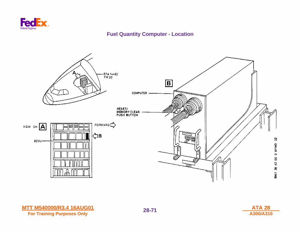
4. COMPUTER
The computer is packaged in a 3MCU case which carries fuel signalconnections on the front face and power and output connections onthe back face. Also on the front face is a RESET/MEMORY CLEARpushbutton switch.
NOTE: SUMMING ADAPTER: One high impedance and one lowimpedance summing adapter is located in each tank wall. The probeswithin each tank are wired through the summing adapters so that, bydisconnecting the adapter, individual probes may be checked for correctcharacteristics.

MTT M540000/R3.4 16AUG01MTT M540000/R3.4 16AUG01For Training Purposes OnlyFor Training Purposes Only
ATA 28ATA 28A300/A310A300/A310
28-28-2727
Wing Tank Fuel System - Fuel Quantity Indication
MTT M540000/R3.4 16AUG01MTT M540000/R3.4 16AUG01For Training Purposes OnlyFor Training Purposes Only
ATA 28ATA 28A300/A310A300/A310
28-28-2828
A300-605R CG Control System (CGCS)
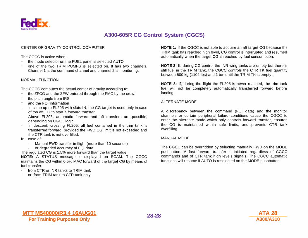
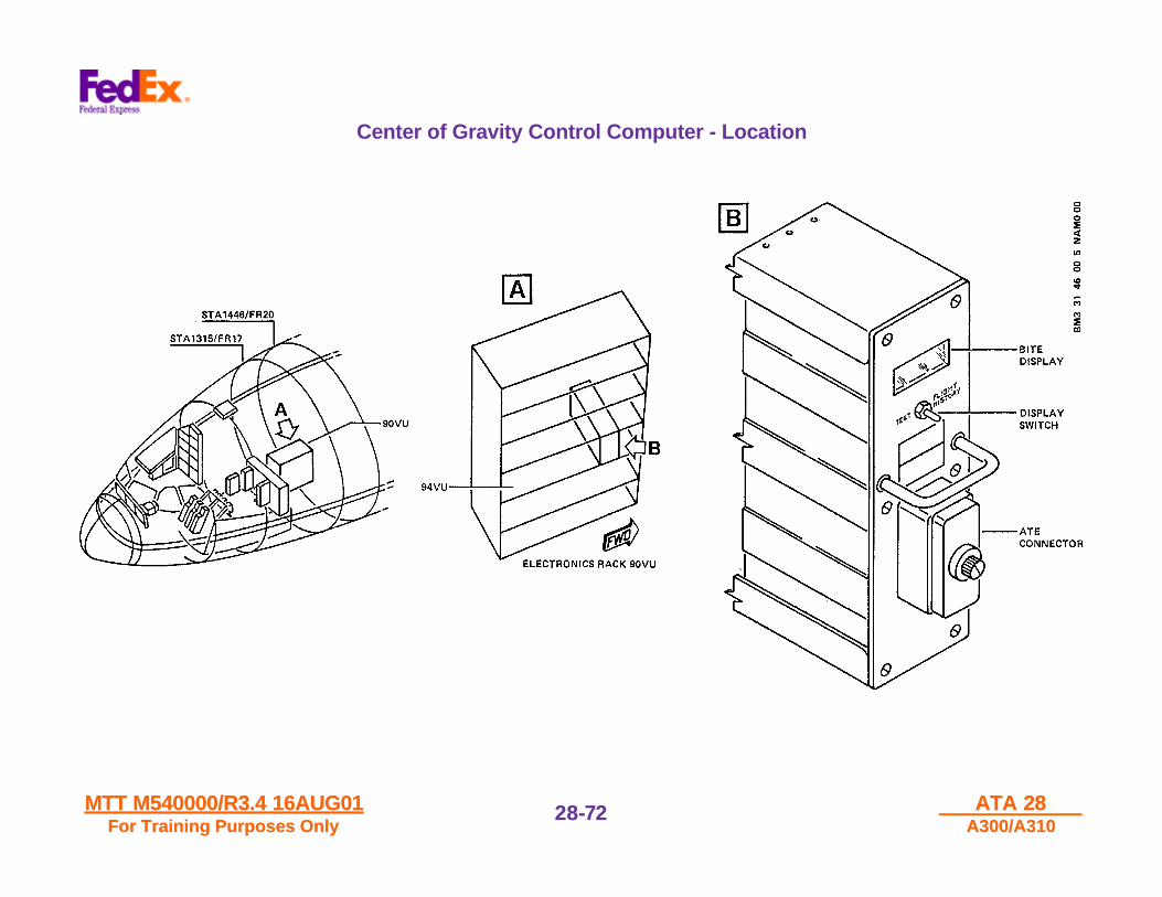
CENTER OF GRAVITY CONTROL COMPUTER
The CGCC is active when:• the mode selector on the FUEL panel is selected AUTO• one of the two TRIM PUMPS is selected on. It has two channels.
Channel 1 is the command channel and channel 2 is monitoring.
NORMAL FUNCTION
The CGCC computes the actual center of gravity according to:• the ZFCG and the ZFW entered through the FMC by the crew.• the pitch angle from IRS• and the FQI information- In climb up to FL205 with slats IN, the CG target is used only in case
of too aft CG to start a forward transfer.- Above FL205, automatic forward and aft transfers are possible,
depending on CGCC logic.- In descent, crossing FL205, all fuel contained in the trim tank is
transferred forward, provided the FWD CG limit is not exceeded andthe CTR tank is not overfilled.
In case of:- Manual FWD transfer in flight (more than 10 seconds)- or degraded accuracy of FQI data
The regulated CG is 1.5% more forward than the target value.NOTE: A STATUS message is displayed on ECAM. The CGCCmaintains the CG within 0.5% MAC forward of the target CG by means offuel transfer:- from CTR or INR tanks to TRIM tank- or, from TRIM tank to CTR tank only.
NOTE 1: If the CGCC is not able to acquire an aft target CG because theTRIM tank has reached high level, CG control is interrupted and resumedautomatically when the target CG is reached by fuel consumption.
NOTE 2: If, during CG control the INR wing tanks are empty but there isstill fuel in the TRIM tank, the CGCC controls the CTR TK fuel quantitybetween 500 kg (1102 lbs) and 1 ton until the TRIM TK is empty.
NOTE 3: If, during the flight the FL205 is never reached, the trim tankfuel will not be completely automatically transferred forward beforelanding.
ALTERNATE MODE
A discrepancy between the command (FQI data) and the monitorchannels or certain peripheral failure conditions cause the CGCC toenter the alternate mode which only controls forward transfer, ensuresthe CG is maintained within safe limits, and prevents CTR tankoverfilling.
MANUAL MODE
The CGCC can be overridden by selecting manually FWD on the MODEpushbutton. A fast forward transfer is initiated regardless of CGCCcommands and of CTR tank high levels signals. The CGCC automaticfunctions will resume if AUTO is reselected on the MODE pushbutton.

MTT M540000/R3.4 16AUG01MTT M540000/R3.4 16AUG01For Training Purposes OnlyFor Training Purposes Only
ATA 28ATA 28A300/A310A300/A310
28-28-2929
A300-605R CG Control System - CGCS

MTT M540000/R3.4 16AUG01MTT M540000/R3.4 16AUG01For Training Purposes OnlyFor Training Purposes Only
ATA 28ATA 28A300/A310A300/A310
28-28-3030
A300-605R CG Control System - CGCS
AUTOMATIC MODE
To operate the system, one or both TRIM TK pump pushbutton switchesmust be pressed in, the TRIM TK AUTO/MODE switch released (out)and Zero Fuel Center of Gravity (ZFCG) and Zero Fuel Weight (ZFW) fedinto the Flight Management System (FMS).
If the CG does not conform to the stored value for the appropriate flightphase, a Forward or Aft transfer will be initiated.
• Forward transfer will normally be in steps of 661 lb. to 772 lb. untilinner tanks are empty, then:
• Forward transfers will be in steps of 1102 lb. These quantities are togive (in cruise) a CG approx. 0.5% forward of target with subsequentfuel burn bringing CG back to target.

MTT M540000/R3.4 16AUG01MTT M540000/R3.4 16AUG01For Training Purposes OnlyFor Training Purposes Only
ATA 28ATA 28A300/A310A300/A310
28-28-3131
A300-605R CG Control System (CGCS) - Trim Tank Pumps

MTT M540000/R3.4 16AUG01MTT M540000/R3.4 16AUG01For Training Purposes OnlyFor Training Purposes Only
ATA 28ATA 28A300/A310A300/A310
28-28-3232
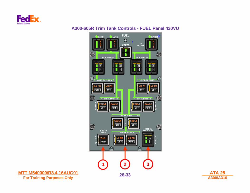
A300-605R Trim Tank Controls - FUEL Panel 430VU
1. TRIM TK MODE PUSHBUTTON SWITCH
• AUTOIn flight, CG is automatically controlled by the CGCC (providedone TRIM TK PUMP at least is selected ON and the TRIM TKISOL VALVE p/b switch is not selected OFF).
• FWDThe FWD light illuminates White. Fuel is transferred forward(provided one TRIM TK PUMP, at least, is selected ON and theTRIM TK ISOL VALVE p/b switch is not selected OFF).
• FAULT lightIlluminates Amber when:- the CGCC is at fault or- the CG moves aft of the limit.
2. TRIM TK PUMP 1 (OR 2) PUSHBUTTON SWITCH
• NORMAL POSITIONThe PUMPS are activated according to the CGCC logic or ifTRIM TK MODE p/b switch is selected FWD.
• OFFThe light illuminates White. The PUMPS cannot be activated.
• LO PRIlluminates Amber if low pressure is detected.
3. TRIM TK ISOL VALVE PUSHBUTTON SWITCH
• AUTOThe valve is OPEN or SHUT depending on its logic.
• OFFThe light illuminates White. The valve is closed.
• FLOW BAR (Green)In line when the valve is open. Flashing during the valve transit.
MTT M540000/R3.4 16AUG01MTT M540000/R3.4 16AUG01For Training Purposes OnlyFor Training Purposes Only
ATA 28ATA 28A300/A310A300/A310
28-28-3333
A300-605R Trim Tank Controls - FUEL Panel 430VU
1 2 3

MTT M540000/R3.4 16AUG01MTT M540000/R3.4 16AUG01For Training Purposes OnlyFor Training Purposes Only
ATA 28ATA 28A300/A310A300/A310
28-28-3434
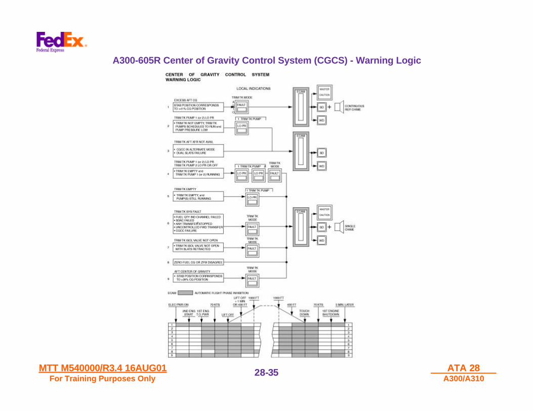
A300-605R Center of Gravity Control System (CGCS) - Warning Logic
Shown below are the different warnings that will occur in theFlight Compartment in the event the fault shown occurs in theCenter of Gravity Control System (CGCS). Also depictedgraphically are the different Flight Phases at which thewarnings will or will not occur.
MTT M540000/R3.4 16AUG01MTT M540000/R3.4 16AUG01For Training Purposes OnlyFor Training Purposes Only
ATA 28ATA 28A300/A310A300/A310
28-28-3535
A300-605R Center of Gravity Control System (CGCS) - Warning Logic
MTT M540000/R3.4 16AUG01MTT M540000/R3.4 16AUG01For Training Purposes OnlyFor Training Purposes Only
ATA 28ATA 28A300/A310A300/A310
28-28-3636
Secondary Fuel Gauging System - Magnetic Level Indicators (MLIs)
GENERAL
The system comprises:• Manual (Magnetic Level Indicator – MLI) stick indicators used to
measure fuel depth in each tank.• An attitude indicator to measure aircraft attitude in roll and pitch
axes.
These two values are then used to read the fuel quantity in the FuelQuantity Charts.
MANUAL (MAGNETIC) STICK INDICATORS
Location: They are located as follows:• two in each outer tank• three in each inner tank• and one in the center tank
DESCRIPTION
When the stick latch is unlocked, the rod can be slowly withdrawn. Whenthe attraction between the fuel stick magnet and the float magnet is felt,the fuel depth can be read on the rod.
NOTE: Do not use force when withdrawing indicator rod as this willdisengage float magnet from the rod magnet and bring the rod downonto the mechanical stop.

MTT M540000/R3.4 16AUG01MTT M540000/R3.4 16AUG01For Training Purposes OnlyFor Training Purposes Only
ATA 28ATA 28A300/A310A300/A310
28-28-3737
A310 Secondary Fuel Gauging System - MLI Component Location

MTT M540000/R3.4 16AUG01MTT M540000/R3.4 16AUG01For Training Purposes OnlyFor Training Purposes Only
ATA 28ATA 28A300/A310A300/A310
28-28-3838
Flight Compartment - FUEL Panel (430 VU)
1. ENG 1, APU and ENG 2 LP VALVE ANNUNCIATORS
The position of the LP valves in the fuel feed lines to both enginesand the APU is displayed. The valves close only when the respectiveFIRE handle is pulled.• In line
Flowbar comes on Green, SHUT light is off. The valve is open.• SHUT
SHUT light comes on Amber, the flowbar is off. The valve isclosed.
2. X FEED FLOWBAR, PUSHBUTTON SWITCHThe P/B switch controls the operation of the fuel cross feed valve.• Released-out
The flowbar comes on Green and crosses the system synoptic.The valve is closed.
• Pressed-InThe flowbar comes on Green and is in line. The valve is open.The indication "FUEL X FEED" is given on the SCAM MEMOpage.
3. ISOL VALVES PUSHBUTTON SWITCHESAll four P/B switches are guarded. They control the position of therelated tankisolation valve in the fuel feed line. The inner tank isolation valvesshut off the fuel supply from the respective center tank pump as well.• P/B switch pressed-in
The valve is opened. The flowbar comes on Green, in line.• P/B switch released-out
The valve is closed. The OFF light comes on White. The flowbaris off.
• Flowbar flashingThe valve position disagrees with the P/B switch setting.
4. OUTR TK/PUMP 1 AND 2 PUSHBUTTON SWITCHESControl tank pumps in outer tanks.• ON (P/B switch pressed-in)
Pump is in operation, but fuel is only fed when delivery pressurefrom inner or center tank pumps drop below threshold.
• OFF (P/B switch released-out)Pump is deactivated, the OFF light comes on White.
• LO PRThe light comes on Amber when the delivery pressure drops due topump failure or fuel starvation. The LO PR light is inhibited when thepump is switched OFF. Illumination of the LO PR light activates theECAM system.

MTT M540000/R3.4 16AUG01MTT M540000/R3.4 16AUG01For Training Purposes OnlyFor Training Purposes Only
ATA 28ATA 28A300/A310A300/A310
28-28-3939
Flight Compartment - FUEL Panel 430 VU
1
2
3
4

MTT M540000/R3.4 16AUG01MTT M540000/R3.4 16AUG01For Training Purposes OnlyFor Training Purposes Only
ATA 28ATA 28A300/A310A300/A310
28-28-4040
A300/A310 Refueling/Defueling System
Description
Two standard pressure refuel/defuel couplings (2.5 Inch) are mountedunder the RH wing. Refueling and defueling may be completed from thisstation. Refueling or defueling is controlled from the refuel/defuel panel atthe outer side of the RH air conditioning compartment. Refuel/defuelvalves which are electrically controlled, open or shut off the fueling linesto the individual tanks. The refuel/defuel valves can be opened manuallyby mechanical controls at the wing LE and the LH main gear well, ifelectrical power is not available.
AUTOMATIC PRESSURE REFUELING
The maximum refueling pressure is 50 PSI. The desired quantity of fuelcan be selected by the fuel quantity preselector on the refuel/defuelpanel. With the automatic loading sequence, the outer tanks are normallycompletely filled while, simultaneously, the remaining fuel load isdistributed to the inner and center tanks based upon the fuel loadrequired.
Refueling is automatically terminated when the preselected quantity isreached. Complete refueling can be achieved in about 24 minutes. Incase of automatic system malfunction, refueling can be controlled byplacing the REFUEL/REFUEL VALVES switches in OPEN or SHUTposition as required. Each tank is fitted with high level sensors to controlthe maximum refuel quantity. If sensors are submerged, thecorresponding refuel/defuel valve closes.
MTT M540000/R3.4 16AUG01MTT M540000/R3.4 16AUG01For Training Purposes OnlyFor Training Purposes Only
ATA 28ATA 28A300/A310A300/A310
28-28-4141
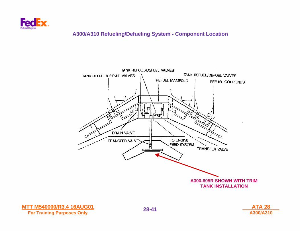
A300/A310 Refueling/Defueling System - Component Location
A300-605R SHOWN WITH TRIMTANK INSTALLATION

MTT M540000/R3.4 16AUG01MTT M540000/R3.4 16AUG01For Training Purposes OnlyFor Training Purposes Only
ATA 28ATA 28A300/A310A300/A310
28-28-4242
Refueling / Defueling System
1. CENTER TANK RELIEF VALVE
The center tank is provided with a relief valve which is open when therefuel/defuel panel door is open. In case of excessive replenishment ofthe tank due to quantity preselector and high level sensor malfunction,the valve enables fuel to be delivered into the RH inner tank. If this valveis not open, center tank refueling (or defueling) is not possible.
2. TRANSFER VALVES
When open, the transfer valve connects the engine fuel feed system tothe refuel/ defuel system. The transfer valve is an electrically-actuatedspherical-plug valve of two inch diameter, similar to the tank isolationvalves. The valve is installed on the inside of the center tank wall by aflange comprised of the body, spherical plug and spindle. The spindleprotrudes through the tank wall and connects with the electrical actuatorinstalled on the outside of the tank.
3. REFUEL/REFUEL VALVES
Each refuel/defuel valve is installed in an aluminum alloy canister havingfuel inlet and outlet connections. The canisters for the inner and outertanks are flange bolted to the aft face of the front spar within the innertank of each wing. The canisters for the center tank and trim tank areflange bolted to the forward dace of the rear spar within the center tank.A second trim tank canister is flange bolted to the rear face of the frontspar in the trim tank.
STANDBY GRAVITY REFUELING
After removing sealing caps on top of the wings, the individual wing tankscan be refueled by gravity, if absolutely required. To refuel the centertank, the fuel transfer procedure has to be applied.
FUEL TRANSFER
On the ground, fuel can be transferred from any tank to any other tank.The transfer valve must be open. The refuel/defuel valves of the tanksupplying fuel must be shut and the fuel tank pump activated. Therefuel/defuel valves of the tanks to be supplied must be open.
REFUELING
Refueling can be performed by suction applied at the refuel/defuelcouplings (up to 11 psi) and/or using the fuel pumps with the transfervalve open.
POWER SUPPLY FOR REFUELING/REFUELING
For refueling and defueling, normally the APU generator should be online or an external electrical power source connected to the aircraft.However; if required, refueling is possible with aircraft battery power. Inthis case battery 1 supplies the FUELING BUS with DC and through theemergency inverter with AC.

MTT M540000/R3.4 16AUG01MTT M540000/R3.4 16AUG01For Training Purposes OnlyFor Training Purposes Only
ATA 28ATA 28A300/A310A300/A310
28-28-4343
Refueling / Defueling System - Component Location

MTT M540000/R3.4 16AUG01MTT M540000/R3.4 16AUG01For Training Purposes OnlyFor Training Purposes Only
ATA 28ATA 28A300/A310A300/A310
28-28-4444
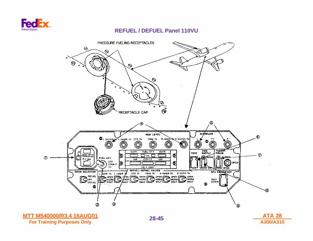
Refuel / Defuel Control Panel 110VU
1. FUEL QUANTITY PRESELECTOR- PRESELECTED Quantity
The quantity for automatic refueling is governed by the setting ofthe preselector. The counter displays the preselected total fuelquantity in lbs x 1000. The Knob must be pulled then turned toadjust the preselected quantity to the desired value.
- ACTUAL QuantityThis counter displays the actual quantity in lbs x 1000. Knobmust be pushed in to read actual.
2. FUEL QTY SWITCHEnables selection on the FUEL QTY indicator of this panel theindication of CTR TK or trim tank or CTR plus trim tank quantity.
3. FUEL QTY INDICATORThe indicator is the same as the one used in the flight compartment.
4. HIGH LEVEL INDICATOR LIGHTSA light comes ran Blue if the high level sensor in a tank issubmerged. The corresponding refuel/defuel valve closesautomatically. Illuminates when pressed to test.
5. OVERFLOW L,R AND TT WARNING LIGHTSA light comes on Amber when the overflow sensor in the relatedvent surge tank is submerged. Illuminates when pressed to test.
6. GUARDED PUSHBUTTON TEST SWITCHWhen pressed-in, high level and overflow sensor circuits are tested.The test is successful when all the six HIGH LEVEL lights and L, Rand TT OVERFLOW lights come on. In addition, a test of the fuelindication circuits is initiated. A successful test is indicated by 8'sdisplayed in all positions of the FUEL QTY indicator windows, andthe preselected and actual quantity indicator.
7. TRANSF VALVE GUARDED SWITCHThis switch controls the transfer valve which connects the fuelcrossfeed line with the refuel/defuel line.• OPEN
The valve is open, fuel can be transferred from one tank to theother by respective fuel pump activation.
• CLOSENormal position, transfer valve closed.
8. PWR SUPPLY GUARDED SWITCHThis switch controls the power supply mode for the refuel/defuelsystem.• NORM
System can be powered by external power source or by APUgenerator.
• BATSystem is powered by BAT 1 and EMER inverter.
9. APU EMERGENCY/SHUT DOWN PUSHBUTTON SWITCHThis P/B switch is guarded. When pressed (in), the APU shutdownsequence is initiated.
MTT M540000/R3.4 16AUG01MTT M540000/R3.4 16AUG01For Training Purposes OnlyFor Training Purposes Only
ATA 28ATA 28A300/A310A300/A310
28-28-4545
REFUEL / DEFUEL Panel 110VU

MTT M540000/R3.4 16AUG01MTT M540000/R3.4 16AUG01For Training Purposes OnlyFor Training Purposes Only
ATA 28ATA 28A300/A310A300/A310
28-28-4646
Refuel / Defuel Panel 110VU
10. REFUEL/DEFUEL VALVES SWITCHESThese switches control the operation of the valves for each individualtank. They are guarded at NORMAL.
NOTE: For REFUEL: trim tank valve will not open unless CTR tank valveis also selected OPEN. For DEFUEL, with fuel in trim tank, CTR tankcannot be defuelled unless trim tank is also selected.
• Valves are controlled by automatic fueling logic depending onposition of the MODE SELECTOR switch and quantitypreselection. Valves close automatically when high level isdetected, and mode switch is in refuel position.
• OPENValves open when the MODE SELECTOR switch is in DEFUELposition or when it is in REFUEL position and high level sensor isnot submerged.
• SHUTValves closed independent from MODE SELECTOR switchposition.
11. MODE SELECTOR SWITCHThis switch controls the operating mode for automatic fueling and theactivation of REFUEL/DEFUEL VALVE switches for manualoperation.• OFF
Refuel/defuel valves closed, switches not activated.• REFUEL
Refuel/defuel valves operated by auto refueling logic (NORMAL)and switches activated for manual operation (OPEN or SHUT),provided the high level sensors are dry.
• DEFUELRefuel/defuel valve switches activated for manual operation(OPEN or SHUT), regardless of level sensor signals.

MTT M540000/R3.4 16AUG01MTT M540000/R3.4 16AUG01For Training Purposes OnlyFor Training Purposes Only
ATA 28ATA 28A300/A310A300/A310
28-28-4747
A300 / Some A310 Refuel / Defuel Control Panel 110VU and Some A310 Panel 476VU
FLIGHT DECK
PANEL 476VURH AIR CONDITIONING FAIRING AREA -
PANEL 110VU
MTT M540000/R3.4 16AUG01MTT M540000/R3.4 16AUG01For Training Purposes OnlyFor Training Purposes Only
ATA 28ATA 28A300/A310A300/A310
28-28-4848
A300 Fuel Level Sensors
DESCRIPTION
Fuel Level Sensors, located in each tank, feed signals to a multichannelamplifier which detects and amplifies the signals and supplies switchingfunctions to the appropriate circuits.
LEVEL SENSOR DESCRIPTION
Each sensor consists of a number of resistors and thermistors, which aremounted on a printed circuit board, and provide a constant temperaturecompensated current supply to sensing thermistors. The circuitry ispotted, in a thermosetting compound, to provide high thermal inertiawhile the sensing thermistor is exposed to the tank environment. Thesensor assembly is mounted in a perforated protective can on a WingTank Rib or Floor Member, as appropriate.
OPERATION
When the sensing thermistor is in air, its temperature is raised by theapplied current. When the thermistor is immersed, the high thermalconductivity of the fuel, in comparison with air, causes the thermistortemperature to fall. The associated change in resistance causes avoltage change to be sensed by the amplifier.
AMPLIFIER (FIN 8QJ)
The rack mounted amplifier is supplied from the aircraft 28VDC Busbarand contains a channel for each level sensor. The amplifier provides thefollowing functions:- A Current Power Supply, limited to intrinsically safe values, for each
sensor.- A Detection Circuit to identify immersion of the sensing thermistor.- A Power Amplifier and switching stage to provide the appropriate
output to the switching circuits.

MTT M540000/R3.4 16AUG01MTT M540000/R3.4 16AUG01For Training Purposes OnlyFor Training Purposes Only
ATA 28ATA 28A300/A310A300/A310
28-28-4949
A300-605R Fuel Level Sensors - Component Location - With Trim Tank
MTT M540000/R3.4 16AUG01MTT M540000/R3.4 16AUG01For Training Purposes OnlyFor Training Purposes Only
ATA 28ATA 28A300/A310A300/A310
28-28-5050
Center Wing Tank - Fuel Vapor Seal
GENERAL DESCRIPTION
VAPOR SEAL / CENTER TANK
The vapor seal comprises a flexible glass fiber membrane coated with anelastomer. Within certain areas, adjacent to equipment in the airconditioning compartment, the vapor seal is made of aluminum alloy. Themembrane is attached to the pressure floor and fuselage sides to providea sealed interspace at the tank front face and lower surface. Themembrane is retained by aluminum alloy clamp strips and bolts.
VENTILATION SYSTEM / CENTER TANK
Air flows from the pressurized zone through a line located at STA2612(FR40/41) which is connected to a transverse distribution pipeimmediately below the pressure floor. The distribution pipe has holesdrilled along its length through which the air flows by cabin to ambientpressure differential.
DRAINAGE AND EXHAUST / CENTER TANK
A drainage and exhaust network at low points in the base of the vaporseal is connected to an outlet in a drain mast located in the fuselagebottom skin. The system network forms the ventilation air exhaust pathand liquid drain path. The drain points are located on each side of thevapor seal at STA2983 (FR47/48) and the drain mast between STA3248(FR52) and STA3301 (FR53).

MTT M540000/R3.4 16AUG01MTT M540000/R3.4 16AUG01For Training Purposes OnlyFor Training Purposes Only
ATA 28ATA 28A300/A310A300/A310
28-28-5151
Center Wing Tank - Vapor Seal - Component Location

MTT M540000/R3.4 16AUG01MTT M540000/R3.4 16AUG01For Training Purposes OnlyFor Training Purposes Only
ATA 28ATA 28A300/A310A300/A310
28-28-5252
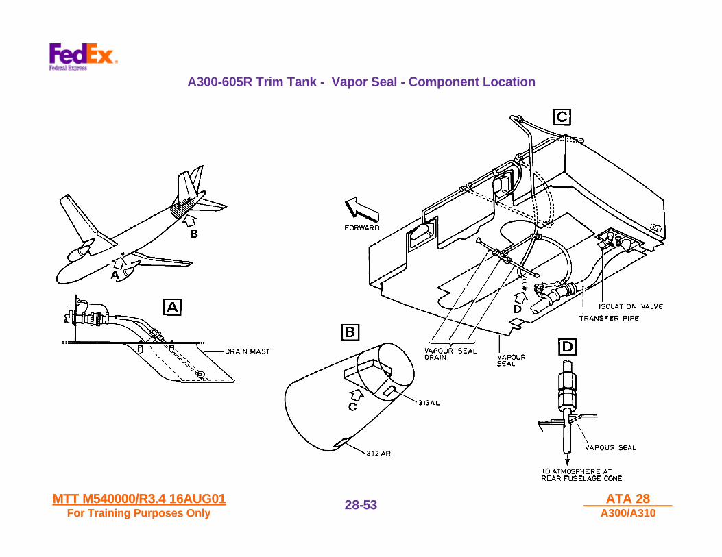
A300-605R Trim Tank - Fuel Vapor Seal
GENERAL DESCRIPTION
VAPOR SEAL/TRIM TANK
The vapor seal comprises a flexible membrane coated with an elastomer.The membrane is attached to the tank structure front, rear and sides upto the horizontal stabilizer cut out cover shield. The membrane isretained by aluminum alloy clamp strips and bolts.
VENTILATION SYSTEM/TRIM TANK
Air flows from the air inlet located at the LH side of the lower rearfuselage cone (FR86/87) via a flexible hose to a T-joint from which twodistribution pipes are connected. Air then flows into the vapor sealinterspace at the front spar area via the distribution pipes, by ambientpressure differential.
DRAINAGE AND EXHAUST SYSTEM/TRIM TANK
A drainage and exhaust network at two low points in the base of the trimtank vapor seal is connected to the trim tank transfer pipe shroud. Theshroud drain line is connected to an outlet in the drain mast located in thefuselage bottom skin between STA3248 (FR52) and STA3301 (FR53).The system network forms the ventilation air exhaust path and the liquiddrain path in the trim tank fuel transfer line and the A.P.U. fuel feed line.
MTT M540000/R3.4 16AUG01MTT M540000/R3.4 16AUG01For Training Purposes OnlyFor Training Purposes Only
ATA 28ATA 28A300/A310A300/A310
28-28-5353
A300-605R Trim Tank - Vapor Seal - Component Location
MTT M540000/R3.4 16AUG01MTT M540000/R3.4 16AUG01For Training Purposes OnlyFor Training Purposes Only
ATA 28ATA 28A300/A310A300/A310
28-28-5454
Left Wing Outer Fuel Tank - Fuel Temperature Probe
GENERAL DESCRIPTION
A Tank Fuel Temperature System provides indication of FuelTemperature on the LH ECAM-MEMO Page. The Fuel TemperatureSensor is positioned in the LH Outer Fuel Tank on the Left Wing RearSpar structure.

MTT M540000/R3.4 16AUG01MTT M540000/R3.4 16AUG01For Training Purposes OnlyFor Training Purposes Only
ATA 28ATA 28A300/A310A300/A310
28-28-5555
Left Wing Outer Fuel Tank - Fuel Temperature Sensor - Component Location
MTT M540000/R3.4 16AUG01MTT M540000/R3.4 16AUG01For Training Purposes OnlyFor Training Purposes Only
ATA 28ATA 28A300/A310A300/A310
28-28-5656
Engine Pylon Assembly - Fuel Line Routing
GENERAL DESCRIPTION
A double walled fuel line leads from the forwardarea of the wing thru the pylon to the enginedisconnect junction box. The sections of the fuel lineare located within pylon compartments.
The double walled fuel line is routed adjacent to theBleed Air System Precooler Assembly. Thepurpose of using hot radiated engine bleed air to theto warm the incoming fuel to the Main Engine FuelSystem prior to being burned in the EngineCombustion Section.
This provides better atomization of the incoming fuelto the engine to increase engine performance due toimproved combustion of the cold fuel from the WingFuel Tanks
Engine and pylon compartments have beendesigned to prevent fluid leakage from coming incontact with an ignition source.

MTT M540000/R3.4 16AUG01MTT M540000/R3.4 16AUG01For Training Purposes OnlyFor Training Purposes Only
ATA 28ATA 28A300/A310A300/A310
28-28-5757
Engine Pylon - Main Engine Fuel Line - Routing Location

MTT M540000/R3.4 16AUG01MTT M540000/R3.4 16AUG01For Training Purposes OnlyFor Training Purposes Only
ATA 28ATA 28A300/A310A300/A310
28-28-5858
Maintenance Panel Controls and Indications - FUEL Test Panel
1. FUEL QTY/FAULT SIM & LO LVL TEST SELECTOR SWITCHAllows testing of the outer tanks low level sensors and the 2channels of the quantity indicating system.
2. FAULT SIM ANNUNCIATOREach FAULT light illuminates White when the selector switch isselected CHAN 1 (or 2) to indicate satisfactory operation of thecorresponding system.
3. SYS MONITOR PUSHBUTTON SWITCHMonitors and tests the quantity indicating system.- Release-out: FAULT light comes on White if a fault is detected
by the incorporated BITE.- Pressed-in: TEST light comes on White. FUEL QTY indicator
displays a code indicating the detected failure.
4. CGCC FAULT LIGHT (A300 Only)Illuminates White if a CGCC fault is detected.
NOTE: A reset of CGCC is only possible if the CGCC bite has beenread.
5. CTR TK RELIEF VALVE ANNUNCIATOR (A300 Only)- OPEN light comes on White when the valve is fully open.- SHUT light comes on White when the valve is fully closed.
6. ENG 1 (or 2) LP (Low Pressure)VALVE ANNUNCIATORFAULT light comes on Amber when:- The valve is closed by one motor only- or one of the two relays provided to isolate the valve opening
supply to its associated motor (in case of failed fire handlecontact) is inoperative.
NOTE : The LP Valve is also called Engine Fire Shutoff Valve.

MTT M540000/R3.4 16AUG01MTT M540000/R3.4 16AUG01For Training Purposes OnlyFor Training Purposes Only
ATA 28ATA 28A300/A310A300/A310
28-28-5959
Maintenance Panel - FUEL Test Panel BITE
1
2
3
4
5
6
A300-605R PANEL SHOWN
WITH CGC SYSTEM TRIM TANK
CGCS = CENTER OF GRAVITY CONTROLSYSTEM

MTT M540000/R3.4 16AUG01MTT M540000/R3.4 16AUG01For Training Purposes OnlyFor Training Purposes Only
ATA 28ATA 28A300/A310A300/A310
28-28-6060
Fuel Tank Access And Working Areas
DESCRIPTION - INNER AND OUTER TANKS
Each Inner and Outer fuel tank is divided into working areascorresponding to the compartments located between Wing StructuralRibs. Each Wing Rib is identified by white color paint on the outboardside of each rib in the mid-position.
Most of these compartments have manholes located in the LH/RH Winglower surface areas.
Compartments not provided with manholes are accessible from adjacentcompartments through manholes in the Wing Ribs internal structuralareas.

MTT M540000/R3.4 16AUG01MTT M540000/R3.4 16AUG01For Training Purposes OnlyFor Training Purposes Only
ATA 28ATA 28A300/A310A300/A310
28-28-6161
Wing Fuel Tank Manhole Covers - Types and Locations
MTT M540000/R3.4 16AUG01MTT M540000/R3.4 16AUG01For Training Purposes OnlyFor Training Purposes Only
ATA 28ATA 28A300/A310A300/A310
28-28-6262
Fuel Tank Access - Center Tank
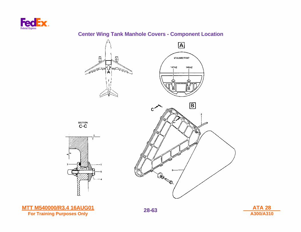
GENERAL DESCRIPTION
The Center Tank is divided into three compartments, separated bybulkheads. Two manholes in the Rear Spar at STA 2982/FR47,accessible from the Hydraulics Bay (Main Landing Gear Wheel Wells),provide access to the two rear compartments through manholes in thebulkheads.
MTT M540000/R3.4 16AUG01MTT M540000/R3.4 16AUG01For Training Purposes OnlyFor Training Purposes Only
ATA 28ATA 28A300/A310A300/A310
28-28-6363
Center Wing Tank Manhole Covers - Component Location

MTT M540000/R3.4 16AUG01MTT M540000/R3.4 16AUG01For Training Purposes OnlyFor Training Purposes Only
ATA 28ATA 28A300/A310A300/A310
28-28-6464
A300-605R Fuel Trim Tank - Tank Access
GENERAL DESCRIPTION
Manholes in Trim Tank lower surface allow access to Rib Compartments.Rib Compartments not provided with a manhole are accessible throughan adjacent compartment. Panel 312AR gives access to the two CenterSection manholes.
Each Trimmable Horizontal Stabilizer (THS) Rib is identified by whitecolor paint on the outboard side of each rib in the mid-position.

MTT M540000/R3.4 16AUG01MTT M540000/R3.4 16AUG01For Training Purposes OnlyFor Training Purposes Only
ATA 28ATA 28A300/A310A300/A310
28-28-6565
A300-605R Trim Tank Access - Manhole Location

MTT M540000/R3.4 16AUG01MTT M540000/R3.4 16AUG01For Training Purposes OnlyFor Training Purposes Only
ATA 28ATA 28A300/A310A300/A310
28-28-6666
A300/A310 Crossfeed Flow Bar Indication Failure - MEL Procedure

MTT M540000/R3.4 16AUG01MTT M540000/R3.4 16AUG01For Training Purposes OnlyFor Training Purposes Only
ATA 28ATA 28A300/A310A300/A310
28-28-6767
A300/A310 Crossfeed Flow Bar Indication Failure - MEL Procedure
MTT M540000/R3.4 16AUG01MTT M540000/R3.4 16AUG01For Training Purposes OnlyFor Training Purposes Only
ATA 28ATA 28A300/A310A300/A310
28-28-6868
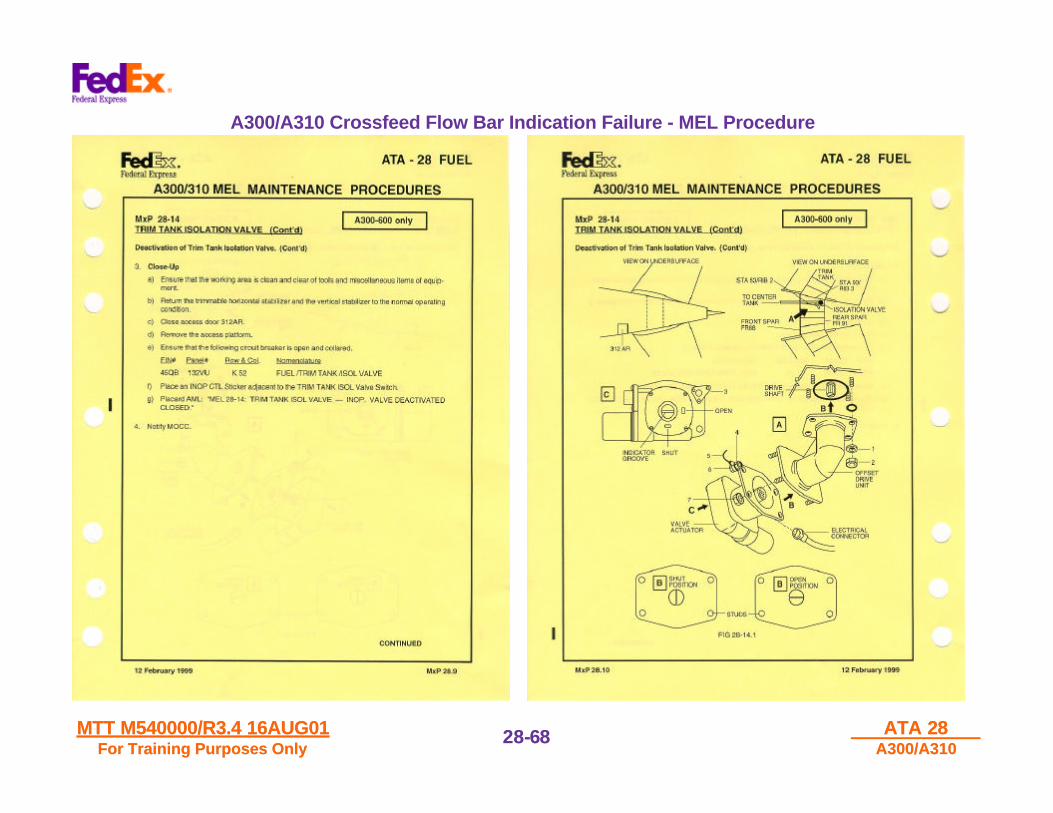
A300/A310 Crossfeed Flow Bar Indication Failure - MEL Procedure

MTT M540000/R3.4 16AUG01MTT M540000/R3.4 16AUG01For Training Purposes OnlyFor Training Purposes Only
ATA 28ATA 28A300/A310A300/A310
28-28-6969
A300/A310 Crossfeed Flow Bar Indication Failure - MEL Procedure
MTT M540000/R3.4 16AUG01MTT M540000/R3.4 16AUG01For Training Purposes OnlyFor Training Purposes Only
ATA 28ATA 28A300/A310A300/A310
28-28-7070
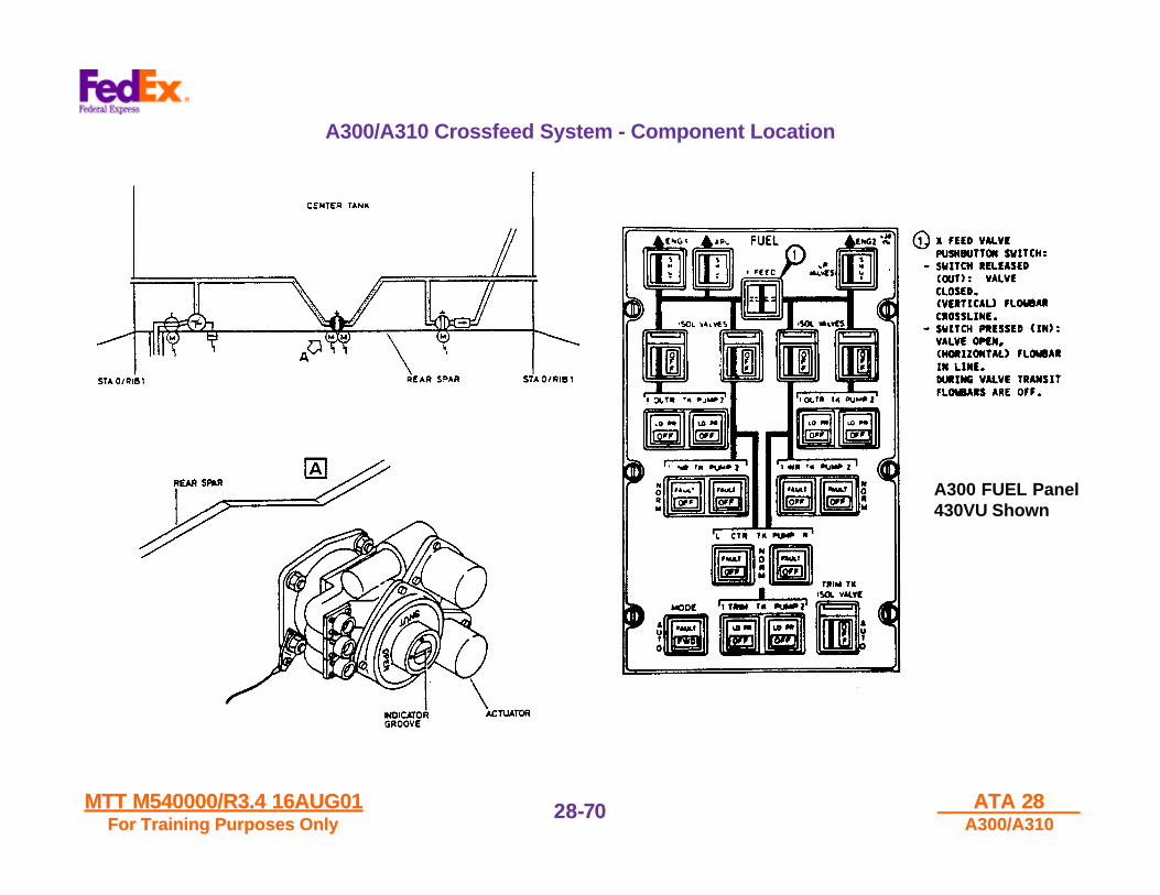
A300/A310 Crossfeed System - Component Location
A300 FUEL Panel430VU Shown
MTT M540000/R3.4 16AUG01MTT M540000/R3.4 16AUG01For Training Purposes OnlyFor Training Purposes Only
ATA 28ATA 28A300/A310A300/A310
28-28-7171
Fuel Quantity Computer - Location
MTT M540000/R3.4 16AUG01MTT M540000/R3.4 16AUG01For Training Purposes OnlyFor Training Purposes Only
ATA 28ATA 28A300/A310A300/A310
28-28-7272
Center of Gravity Control Computer - Location

MTT M540000/R3.4 16AUG01MTT M540000/R3.4 16AUG01For Training Purposes OnlyFor Training Purposes Only
ATA 28ATA 28A300/A310A300/A310
28-28-7373
Fuel Level Amplifier - Location

MTT M540000/R3.4 16AUG01MTT M540000/R3.4 16AUG01For Training Purposes OnlyFor Training Purposes Only
ATA 28ATA 28A300/A310A300/A310
28-28-7474
THIS PAGE INTENTIONALLY
LEFT BLANK
ATA 28 - END
COURSE CODE - M540000


