AIRBUS A320 Flight Mode Annunciator
12
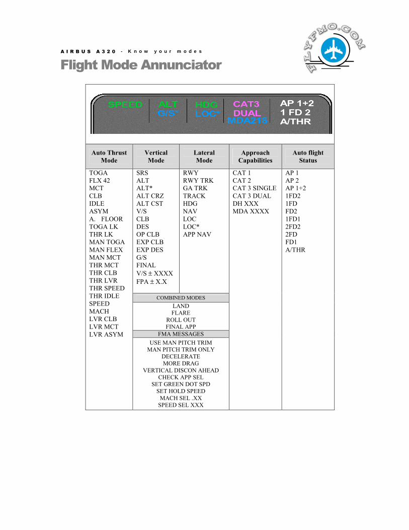
AIRBUS A320 - Know your modes Flight Mode Annunciator Auto Thrust Mode Vertical Mode Lateral Mode Approach Capabilities Auto flight Status SRS ALT ALT* ALT CRZ ALT CST V/S CLB DES OP CLB EXP CLB EXP DES G/S FINAL V/S ± XXXX FPA ± X.X RWY RWY TRK GA TRK TRACK HDG NAV LOC LOC* APP NAV COMBINED MODES LAND FLARE ROLL OUT FINAL APP FMA MESSAGES TOGA FLX 42 MCT CLB IDLE ASYM A. FLOOR TOGA LK THR LK MAN TOGA MAN FLEX MAN MCT THR MCT THR CLB THR LVR THR SPEED THR IDLE SPEED MACH LVR CLB LVR MCT LVR ASYM USE MAN PITCH TRIM MAN PITCH TRIM ONLY DECELERATE MORE DRAG VERTICAL DISCON AHEAD CHECK APP SEL SET GREEN DOT SPD SET HOLD SPEED MACH SEL .XX SPEED SEL XXX CAT 1 CAT 2 CAT 3 SINGLE CAT 3 DUAL DH XXX MDA XXXX AP 1 AP 2 AP 1+2 1FD2 1FD FD2 1FD1 2FD2 2FD FD1 A/THR
Transcript of AIRBUS A320 Flight Mode Annunciator
A I R B U S A 3 2 0 - K n o w y o u r m o d e s
Flight Mode Annunciator
Auto Thrust Mode
Vertical Mode
Lateral Mode
Approach Capabilities
Auto flight Status
SRS ALT ALT* ALT CRZ ALT CST V/S CLB DES OP CLB EXP CLB EXP DES G/S FINAL V/S ± XXXX FPA ± X.X
RWY RWY TRK GA TRK TRACK HDG NAV LOC LOC* APP NAV
COMBINED MODES LAND FLARE
ROLL OUT FINAL APP
FMA MESSAGES
TOGA FLX 42 MCT CLB IDLE ASYM A. FLOOR TOGA LK THR LK MAN TOGA MAN FLEX MAN MCT THR MCT THR CLB THR LVR THR SPEED THR IDLE SPEED MACH LVR CLB LVR MCT LVR ASYM USE MAN PITCH TRIM
MAN PITCH TRIM ONLY DECELERATE MORE DRAG
VERTICAL DISCON AHEAD CHECK APP SEL
SET GREEN DOT SPD SET HOLD SPEED
MACH SEL .XX SPEED SEL XXX
CAT 1 CAT 2 CAT 3 SINGLE CAT 3 DUAL DH XXX MDA XXXX
AP 1 AP 2 AP 1+2 1FD2 1FD FD2 1FD1 2FD2 2FD FD1 A/THR
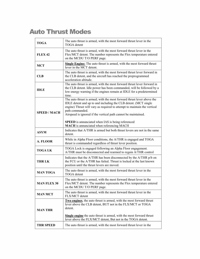
Auto Thrust Modes TOGA The auto thrust is armed, with the most forward thrust lever in the
TOGA detent
FLEX 42 The auto thrust is armed, with the most forward thrust lever in the Flex/MCT detent. The number represents the Flex temperature entered on the MCDU T/O PERF page.
MCT Single Engine: The auto thrust is armed, with the most forward thrust lever in the MCT detent.
CLB The auto thrust is armed, with the most forward thrust lever forward in the CLB detent, and the aircraft has reached the preprogrammed acceleration altitude.
IDLE
The auto thrust is armed, with the most forward thrust lever forward in the CLB detent. Idle power has been commanded, will be followed by a low energy warning if the engines remain at IDLE for a predetermined time.
SPEED / MACH
The auto thrust is armed; with the most forward thrust lever above the IDLE detent and up to and including the CLB detent. (MCT single engine) Thrust will vary as required to attempt to maintain the vertical path commanded. Airspeed is ignored if the vertical path cannot be maintained. SPEED is annunciated when IAS is being referenced MACH is annunciated when referencing MACH
ASYM Indicates that A/THR is armed but both thrust levers are not in the same detent.
A. FLOOR While in Alpha Floor conditions, the A/THR is engaged and TOGA thrust is commanded regardless of thrust lever position.
TOGA LK TOGA Lock is engaged following an Alpha Floor engagement. A/THR must be disconnected and rearmed to regain A/THR control
THR LK Indicates that the A/THR has been disconnected by the A/THR p/b on the FCU or the A/THR has failed. Thrust is locked at the last known position until the thrust levers are moved.
MAN TOGA The auto thrust is armed, with the most forward thrust lever in the TOGA detent
MAN FLEX 30 The auto thrust is armed, with the most forward thrust lever in the Flex/MCT detent. The number represents the Flex temperature entered on the MCDU T/O PERF page.
MAN MCT The auto thrust is armed, with the most forward thrust lever in the FLX/MCT detent
MAN THR
Two engines, the auto thrust is armed, with the most forward thrust lever above the CLB detent, BUT not in the FLX/MCT or TOGA detent. Single engine the auto thrust is armed, with the most forward thrust lever above the FLX/MCT detent, But not in the TOGA detent.
THR SPEED The auto thrust is armed, with the most forward thrust lever in the
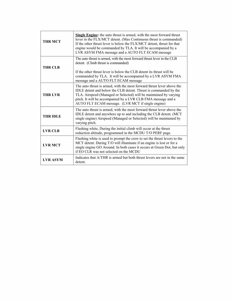
THR MCT
Single Engine: the auto thrust is armed, with the most forward thrust lever in the FLX/MCT detent. (Max Continuous thrust is commanded) If the other thrust lever is below the FLX/MCT detent, thrust for that engine would be commanded by TLA. It will be accompanied by a LVR ASYM FMA message and a AUTO FLT ECAM message
THR CLB
The auto thrust is armed, with the most forward thrust lever in the CLB detent. (Climb thrust is commanded)
If the other thrust lever is below the CLB detent its thrust will be commanded by TLA. It will be accompanied by a LVR ASYM FMA message and a AUTO FLT ECAM message
THR LVR
The auto thrust is armed, with the most forward thrust lever above the IDLE detent and below the CLB detent. Thrust is commanded by the TLA. Airspeed (Managed or Selected) will be maintained by varying pitch. It will be accompanied by a LVR CLB FMA message and a AUTO FLT ECAM message. (LVR MCT if single engine)
THR IDLE
The auto thrust is armed; with the most forward thrust lever above the IDLE detent and anywhere up to and including the CLB detent. (MCT single engine) Airspeed (Managed or Selected) will be maintained by varying pitch.
LVR CLB Flashing white, During the initial climb will occur at the thrust reduction altitude, programmed in the MCDU T/O PERF page.
LVR MCT
Flashing white is used to prompt the crew to set the thrust levers to the MCT detent. During T/O will illuminate if an engine is lost or for a single engine GO Around. In both cases it occurs at Green Dot, but only if EO CLR was not selected on the MCDU
LVR ASYM Indicates that A/THR is armed but both thrust levers are not in the same detent.
Vertical Modes
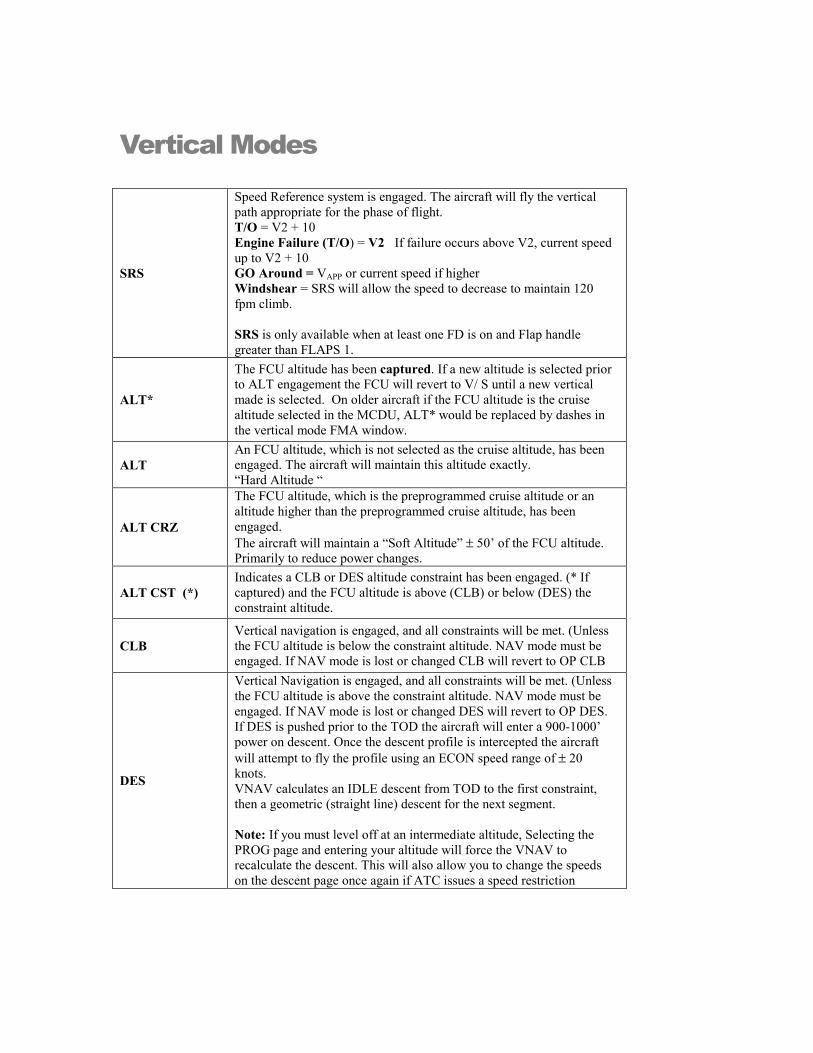
SRS
Speed Reference system is engaged. The aircraft will fly the vertical path appropriate for the phase of flight. T/O = V2 + 10 Engine Failure (T/O) = V2 If failure occurs above V2, current speed up to V2 + 10 GO Around = VAPP or current speed if higher Windshear = SRS will allow the speed to decrease to maintain 120 fpm climb. SRS is only available when at least one FD is on and Flap handle greater than FLAPS 1.
ALT*
The FCU altitude has been captured. If a new altitude is selected prior to ALT engagement the FCU will revert to V/ S until a new vertical made is selected. On older aircraft if the FCU altitude is the cruise altitude selected in the MCDU, ALT* would be replaced by dashes in the vertical mode FMA window.
ALT An FCU altitude, which is not selected as the cruise altitude, has been engaged. The aircraft will maintain this altitude exactly. “Hard Altitude “
ALT CRZ
The FCU altitude, which is the preprogrammed cruise altitude or an altitude higher than the preprogrammed cruise altitude, has been engaged. The aircraft will maintain a “Soft Altitude” ± 50’ of the FCU altitude. Primarily to reduce power changes.
ALT CST (*) Indicates a CLB or DES altitude constraint has been engaged. (* If captured) and the FCU altitude is above (CLB) or below (DES) the constraint altitude.
CLB Vertical navigation is engaged, and all constraints will be met. (Unless the FCU altitude is below the constraint altitude. NAV mode must be engaged. If NAV mode is lost or changed CLB will revert to OP CLB
DES
Vertical Navigation is engaged, and all constraints will be met. (Unless the FCU altitude is above the constraint altitude. NAV mode must be engaged. If NAV mode is lost or changed DES will revert to OP DES. If DES is pushed prior to the TOD the aircraft will enter a 900-1000’ power on descent. Once the descent profile is intercepted the aircraft will attempt to fly the profile using an ECON speed range of ± 20 knots. VNAV calculates an IDLE descent from TOD to the first constraint, then a geometric (straight line) descent for the next segment. Note: If you must level off at an intermediate altitude, Selecting the PROG page and entering your altitude will force the VNAV to recalculate the descent. This will also allow you to change the speeds on the descent page once again if ATC issues a speed restriction
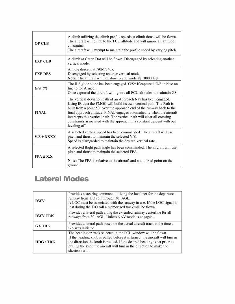
OP CLB
A climb utilizing the climb profile speeds at climb thrust will be flown. The aircraft will climb to the FCU altitude and will ignore all altitude constraints. The aircraft will attempt to maintain the profile speed by varying pitch.
EXP CLB A climb at Green Dot will be flown. Disengaged by selecting another vertical mode.
EXP DES An idle descent at .80M/340K Disengaged by selecting another vertical mode. Note: The aircraft will not slow to 250 knots @ 10000 feet.
G/S (*) The ILS glide slope has been engaged. G/S* If captured, G/S in blue on line to for Armed. Once captured the aircraft will ignore all FCU altitudes to maintain GS.
FINAL
The vertical deviation path of an Approach Nav has been engaged. Using IR data the FMGC will build its own vertical path. The Path is built from a point 50’ over the approach end of the runway back to the final approach altitude. FINAL engages automatically when the aircraft intercepts this vertical path. The vertical path will clear all crossing constraints associated with the approach in a constant descent with out leveling off.
V/S ±±±± XXXX A selected vertical speed has been commanded. The aircraft will use pitch and thrust to maintain the selected V/S. Speed is disregarded to maintain the desired vertical rate.
FPA ±±±± X.X
A selected flight path angle has been commanded. The aircraft will use pitch and thrust to maintain the selected FPA. Note: The FPA is relative to the aircraft and not a fixed point on the ground.
Lateral Modes
RWY
Provides a steering command utilizing the localizer for the departure runway from T/O roll through 30’ AGL. A LOC must be associated with the runway in use. If the LOC signal is lost during the T/O roll a memorized track will be flown.
RWY TRK Provides a lateral path along the extended runway centerline for all runways from 30’ AGL, Unless NAV mode is engaged.
GA TRK Provides a lateral path based on the actual aircraft track at the time a GA was initiated.
HDG / TRK
The heading or track selected in the FCU window will be flown. If the heading knob is pulled before it is turned, the aircraft will turn in the direction the knob is rotated. If the desired heading is set prior to pulling the knob the aircraft will turn in the direction to make the shortest turn.
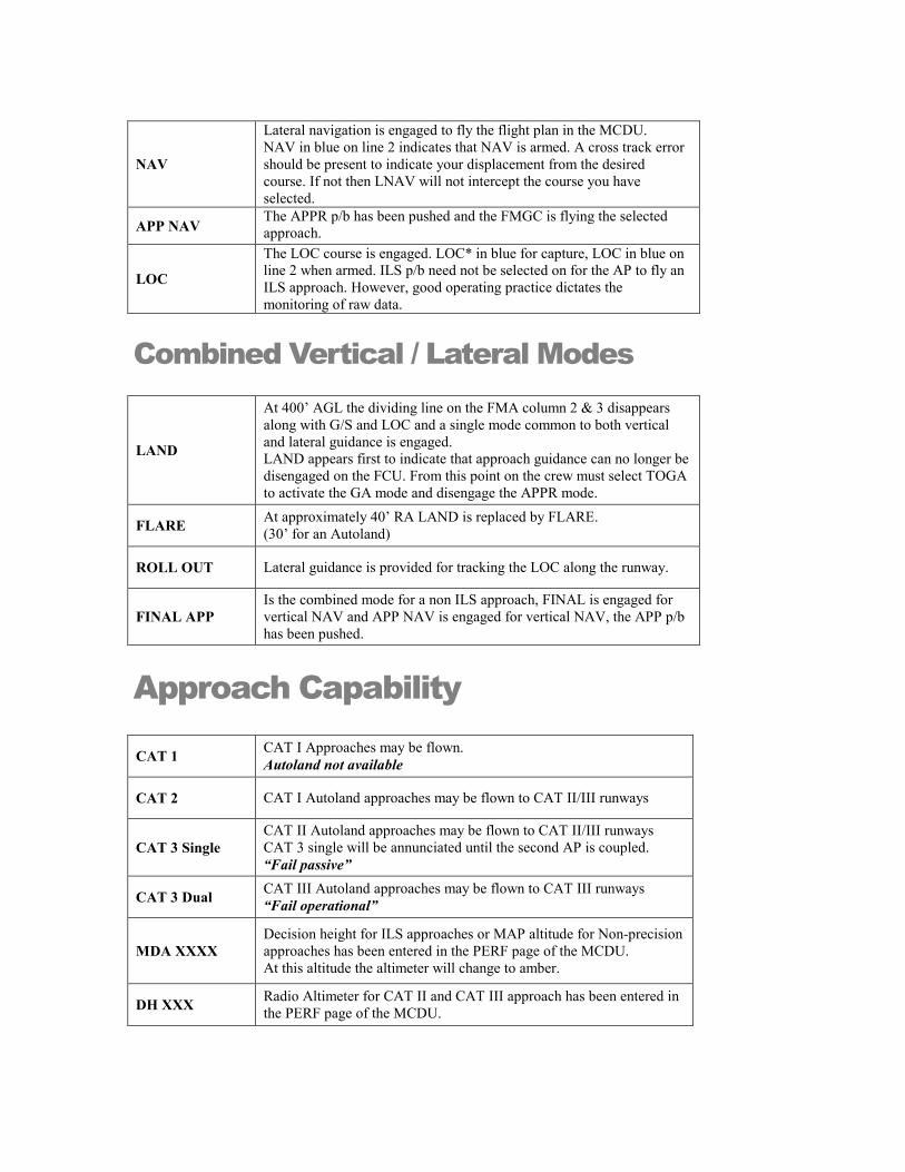
NAV
Lateral navigation is engaged to fly the flight plan in the MCDU. NAV in blue on line 2 indicates that NAV is armed. A cross track error should be present to indicate your displacement from the desired course. If not then LNAV will not intercept the course you have selected.
APP NAV The APPR p/b has been pushed and the FMGC is flying the selected approach.
LOC
The LOC course is engaged. LOC* in blue for capture, LOC in blue on line 2 when armed. ILS p/b need not be selected on for the AP to fly an ILS approach. However, good operating practice dictates the monitoring of raw data.
Combined Vertical / Lateral Modes
LAND
At 400’ AGL the dividing line on the FMA column 2 & 3 disappears along with G/S and LOC and a single mode common to both vertical and lateral guidance is engaged. LAND appears first to indicate that approach guidance can no longer be disengaged on the FCU. From this point on the crew must select TOGA to activate the GA mode and disengage the APPR mode.
FLARE At approximately 40’ RA LAND is replaced by FLARE. (30’ for an Autoland)
ROLL OUT Lateral guidance is provided for tracking the LOC along the runway.
FINAL APP Is the combined mode for a non ILS approach, FINAL is engaged for vertical NAV and APP NAV is engaged for vertical NAV, the APP p/b has been pushed.
Approach Capability
CAT 1 CAT I Approaches may be flown. Autoland not available
CAT 2 CAT I Autoland approaches may be flown to CAT II/III runways
CAT 3 Single CAT II Autoland approaches may be flown to CAT II/III runways CAT 3 single will be annunciated until the second AP is coupled. “Fail passive”
CAT 3 Dual CAT III Autoland approaches may be flown to CAT III runways “Fail operational”
MDA XXXX Decision height for ILS approaches or MAP altitude for Non-precision approaches has been entered in the PERF page of the MCDU. At this altitude the altimeter will change to amber.
DH XXX Radio Altimeter for CAT II and CAT III approach has been entered in the PERF page of the MCDU.
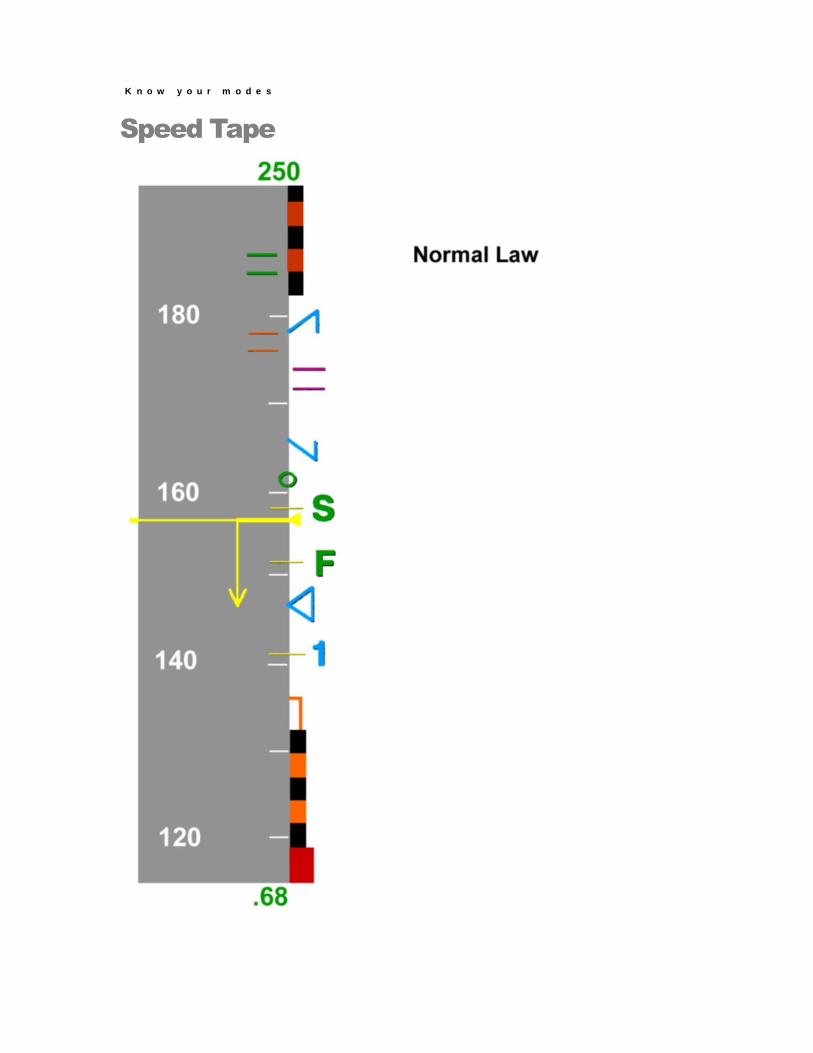
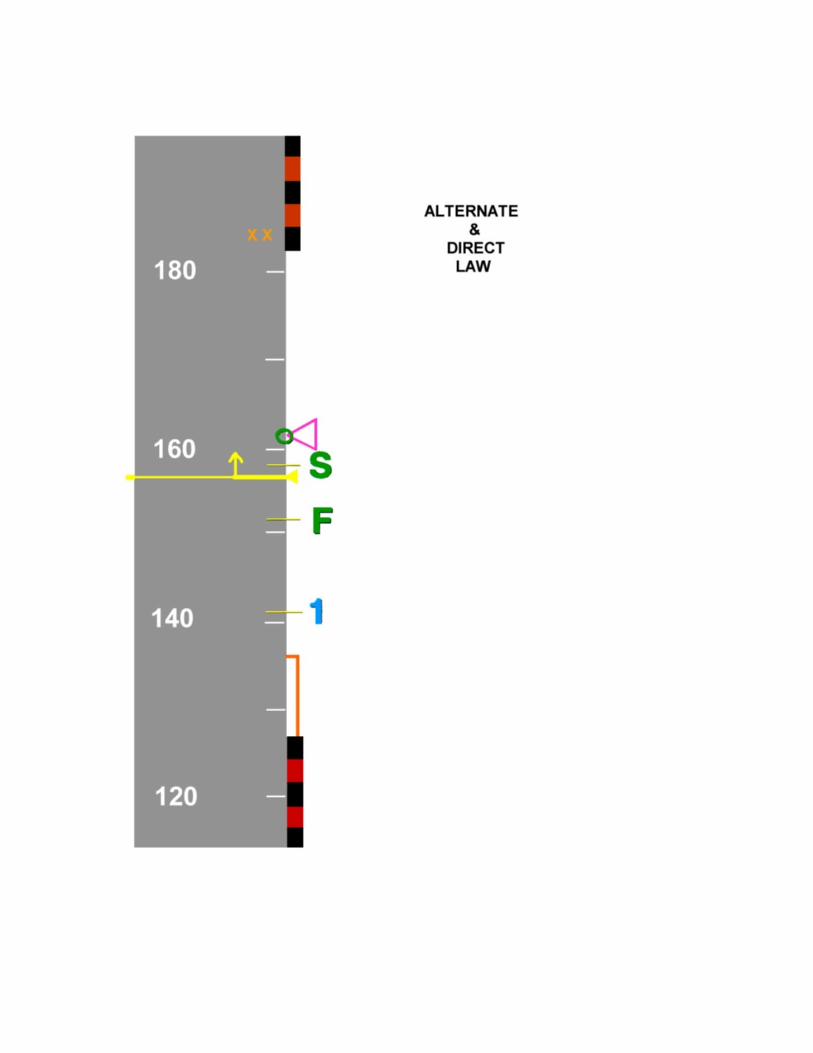
Speed Tape
K n o w y o u r m o d e s
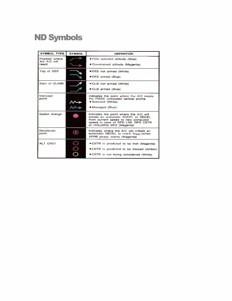
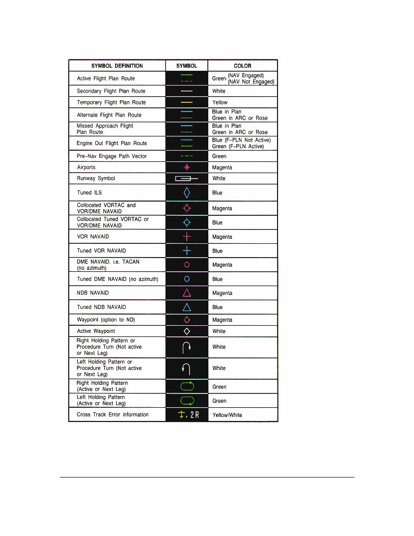
ND Symbols
MBH
Typewriter
Situational awareness, all the time more self confidence Bruno Mecha | [email protected]
A319/A320/A321 FMGS – AP / FD modes
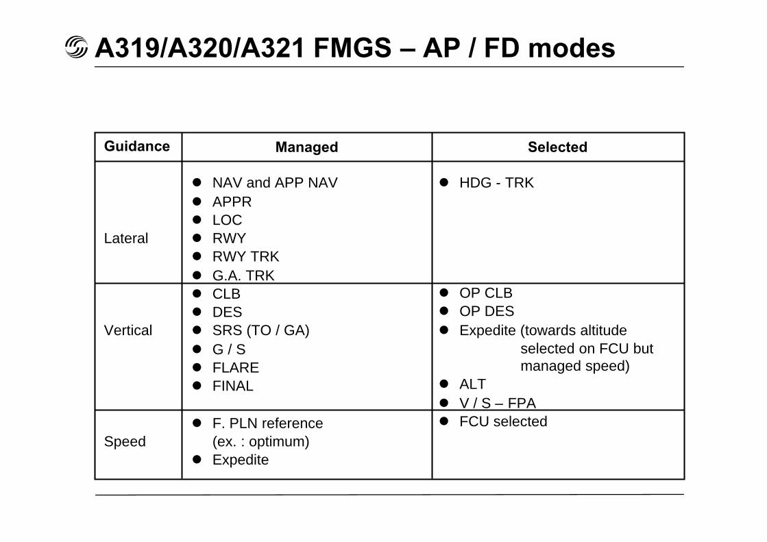
Guidance
Lateral
Vertical
Speed
Managed Selected
NAV and APP NAV APPR LOC RWY RWY TRK G.A. TRK CLB DES SRS (TO / GA) G / S FLARE FINAL
F. PLN reference(ex. : optimum)
Expedite
HDG - TRK
OP CLB OP DES Expedite (towards altitude
selected on FCU butmanaged speed)
ALT V / S – FPA FCU selected
A319/A320/A321 FMGS – AP / FD modes
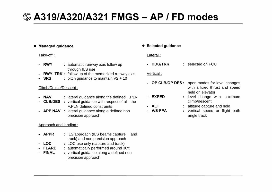
Managed guidance
Take-off :
- RWY : automatic runway axis follow upthrough ILS use
- RWY. TRK : follow up of the memorized runway axis- SRS : pitch guidance to maintain V2 + 10
Climb/Cruise/Descent :
- NAV : lateral guidance along the defined F.PLN- CLB/DES : vertical guidance with respect of all the
F.PLN defined constraints- APP NAV : lateral guidance along a defined non
precision approach
Approach and landing :
- APPR : ILS approach (ILS beams capture andtrack) and non precision approach
- LOC : LOC use only (capture and track)- FLARE : automatically performed around 30ft- FINAL : vertical guidance along a defined non
precision approach
Selected guidance
Lateral :
- HDG/TRK : selected on FCU
Vertical :
- OP CLB/OP DES : open modes for level changeswith a fixed thrust and speedheld on elevator
- EXPED : level change with maximumclimb/descent
- ALT : altitude capture and hold- V/S-FPA : vertical speed or flight path
angle track