Airborne Particle Counter - Flukeassets.fluke.com/manuals/985_____umeng0000.pdf · this warranty is...
32
March 2012 © 2012 Fluke Corporation. All rights reserved. Specifications are subject to change without notice. All product names are trademarks of their respective companies. 985 Airborne Particle Counter Users Manual
Transcript of Airborne Particle Counter - Flukeassets.fluke.com/manuals/985_____umeng0000.pdf · this warranty is...

March 2012 © 2012 Fluke Corporation. All rights reserved. Specifications are subject to change without notice. All product names are trademarks of their respective companies.
985 Airborne Particle Counter
Users Manual

LIMITED WARRANTY AND LIMITATION OF LIABILITY
Each Fluke product is warranted to be free from defects in material and workmanship under normal use and service. The warranty period is one year and begins on the date of shipment. Parts, product repairs, and services are warranted for 90 days. This warranty extends only to the original buyer or end-user customer of a Fluke authorized reseller, and does not apply to fuses, disposable batteries, or to any product which, in Fluke's opinion, has been misused, altered, neglected, contaminated, or damaged by accident or abnormal conditions of operation or handling. Fluke warrants that software will operate substantially in accordance with its functional specifications for 90 days and that it has been properly recorded on non-defective media. Fluke does not warrant that software will be error free or operate without interruption. Fluke authorized resellers shall extend this warranty on new and unused products to end-user customers only but have no authority to extend a greater or different warranty on behalf of Fluke. Warranty support is available only if product is purchased through a Fluke authorized sales outlet or Buyer has paid the applicable international price. Fluke reserves the right to invoice Buyer for importation costs of repair/replacement parts when product purchased in one country is submitted for repair in another country. Fluke's warranty obligation is limited, at Fluke's option, to refund of the purchase price, free of charge repair, or replacement of a defective product which is returned to a Fluke authorized service center within the warranty period. To obtain warranty service, contact your nearest Fluke authorized service center to obtain return authorization information, then send the product to that service center, with a description of the difficulty, postage and insurance prepaid (FOB Destination). Fluke assumes no risk for damage in transit. Following warranty repair, the product will be returned to Buyer, transportation prepaid (FOB Destination). If Fluke determines that failure was caused by neglect, misuse, contamination, alteration, accident, or abnormal condition of operation or handling, including overvoltage failures caused by use outside the product’s specified rating, or normal wear and tear of mechanical components, Fluke will provide an estimate of repair costs and obtain authorization before commencing the work. Following repair, the product will be returned to the Buyer transportation prepaid and the Buyer will be billed for the repair and return transportation charges (FOB Shipping Point). THIS WARRANTY IS BUYER'S SOLE AND EXCLUSIVE REMEDY AND IS IN LIEU OF ALL OTHER WARRANTIES, EXPRESS OR IMPLIED, INCLUDING BUT NOT LIMITED TO ANY IMPLIED WARRANTY OF MERCHANTABILITY OR FITNESS FOR A PARTICULAR PURPOSE. FLUKE SHALL NOT BE LIABLE FOR ANY SPECIAL, INDIRECT, INCIDENTAL, OR CONSEQUENTIAL DAMAGES OR LOSSES, INCLUDING LOSS OF DATA, ARISING FROM ANY CAUSE OR THEORY. Since some countries or states do not allow limitation of the term of an implied warranty, or exclusion or limitation of incidental or consequential damages, the limitations and exclusions of this warranty may not apply to every buyer. If any provision of this Warranty is held invalid or unenforceable by a court or other decision-maker of competent jurisdiction, such holding will not affect the validity or enforceability of any other provision.
Fluke Corporation P.O. Box 9090 Everett, WA 98206-9090 U.S.A.
Fluke Europe B.V. P.O. Box 1186 5602 BD Eindhoven The Netherlands
11/99

i
Table of Contents
Title Page
Introduction .................................................................................................................... 1 How to Contact Fluke ..................................................................................................... 1 Applications .................................................................................................................... 1 Safety Information .......................................................................................................... 2 Battery ............................................................................................................................ 3 Product Overview ........................................................................................................... 3
The Buttons ............................................................................................................... 5 Product Connections ................................................................................................. 6 Charge Base Connections ......................................................................................... 7
Operation ....................................................................................................................... 8 Power On/Off ............................................................................................................. 8 Product Test .............................................................................................................. 8 How to Purge the Product Sensor ............................................................................. 8 How to Take a Sample .............................................................................................. 9 Navigation Menu........................................................................................................ 9

985 Users Manual
ii
Sample Screen Menu ............................................................................................... 10 Buffered Data Menu .................................................................................................. 11 Setup Menus ............................................................................................................. 11 Sample Setup Submenus ......................................................................................... 13
Alarm Setup Submenu ......................................................................................... 13 Data Display Setup Submenu .............................................................................. 13 Setting the Method of Counting Data ................................................................... 14 Location Setup Submenu ..................................................................................... 14
Communication Setup Submenus ............................................................................. 15 Communication Setup .......................................................................................... 15 General Setup Submenu ...................................................................................... 15 Diagnostics Submenu .......................................................................................... 15 Login Submenu .................................................................................................... 16 Trend Data ........................................................................................................... 17
Data Export .................................................................................................................... 18 How to Move Product Data to a PC with a USB Cable ............................................. 18 How to Move Product Data to a Flash USB Drive ..................................................... 18 How to Move Product Data with an Ethernet Cable .................................................. 19
Maintenance .................................................................................................................. 21 Specifications ................................................................................................................ 22
General ..................................................................................................................... 22 Environmental ........................................................................................................... 23

iii
List of Tables
Table Title Page
1. Symbols ................................................................................................................................. 3 2. Product Components ............................................................................................................. 5 3. Buttons .................................................................................................................................. 5 4. Product Connections ............................................................................................................. 6 5. Charge Base Connections ..................................................................................................... 7 6. Main Menu Icons ................................................................................................................... 9 7. Sample Options ..................................................................................................................... 12 8. Sample Setup Submenus ...................................................................................................... 13 9. Location Submenu Icons ....................................................................................................... 14 10. Communication Submenu Icons ............................................................................................ 15

985 Users Manual
iv

v
List of Figures
Figure Title Page
1. Product Components ............................................................................................................. 4 2. Product Connections ............................................................................................................. 6 3. Charge Base Connections ..................................................................................................... 7 4. Sample Screen ...................................................................................................................... 10 5. Exported Data ....................................................................................................................... 20

985 Users Manual
vi

1
Introduction The Fluke 985 Airborne Particle Counter (the Product) is a portable instrument that measures and reports air contamination.
The Product stores 10,000 samples in memory and records the date, time, counts, and sample volume of each sample.
Use the supplied USB cable, an Ethernet connection, or a flash USB drive (not supplied) to download data to a PC.
How to Contact Fluke To contact Fluke, call one of the following telephone numbers:
• Technical Support USA: 1-800-44-FLUKE (1-800-443-5853)
• Calibration/Repair USA: 1-888-99-FLUKE (1-888-993-5853)
• Canada: 1-800-36-FLUKE (1-800-363-5853)
• Europe: +31 402-675-200
• Japan: +81-3-6714-3114
• Singapore: +65-6799-5566
• Anywhere in the world: +1-425-446-5500
Or, visit Fluke's website at www.fluke.com.
To register your product, visit http://register.fluke.com.
To view, print, or download the latest manual supplement, visit http://us.fluke.com/usen/support/manuals.
Applications The Particle Counter can be used to:
• Monitor cleanrooms • Investigate indoor air quality • Monitor gowning rooms • Test filter seals • Locate particle contamination sources • Monitor particle size distributions

985 Users Manual
2
Safety Information A Warning identifies conditions and procedures that are dangerous to the user. A Caution identifies conditions and procedures that can cause damage to the Product or the equipment under test.
Warning
To prevent possible electrical shock, fire, or personal injury: • The Product contains a laser device and
a rechargeable lithium battery pack. Do not disassemble this Product, it contains no user-serviceable parts.
• Do not use, and disable the Product if it is damaged.
• Use the Product only as specified or hazardous laser radiation exposure can occur.
• Do not open the Product. The laser beam is dangerous to eyes. Have the Product repaired only by an approved technical site.
• Do not look directly into the laser with optical tools (for example, binoculars, telescopes, microscopes). Optical tools can focus the laser and be dangerous to the eye.
• Do not use the Product if it operates incorrectly.
• Read the entire Users Manual before using the Product.

Airborne Particle Counter Battery
3
Table 1 tells you about symbols used on the Product and in this manual.
Table 1. Symbols
Symbol Description
Risk of Danger. Important information. See Manual.
Hazardous voltage. Risk of electrical shock.
Do not dispose of this product as unsorted municipal waste. Go to Fluke’s website for recycling information.
Conforms to European Union directives.
Warning. Laser.
Conforms to relevant Australian standards.
This product contains a Lithium-ion battery. Do not mix with the solid waste stream. Spent batteries should be disposed of by a qualified recycler or hazardous materials handler per local regulations. Contact your authorized Fluke Service Center for recycling information.
Battery A rechargeable Lithium-ion battery powers the Product. After you unpack and examine the Product, fully charge the battery before the first use. After the initial charge, charge the battery when the battery icon on the screen shows that battery power is low.
To charge the battery:
1. Put the Product on the Charge Base.
2. Connect the ac adapter to a power source.
3. Connect the ac adapter to the dc input socket on the Charge Base.
An amber light on the front of the Charge Base shows that the base is powered. The light changes to green when the Product is connected to the base.
If the ac adapter cord is connected to the Product, a green light shows above the power jack.
If the Product is on, the battery icon flashes as the battery charges. The icon is solid (does not flash) when the battery is fully charged. Approximately 3.5 hours is necessary to charge a discharged battery. The battery is not user-serviceable.
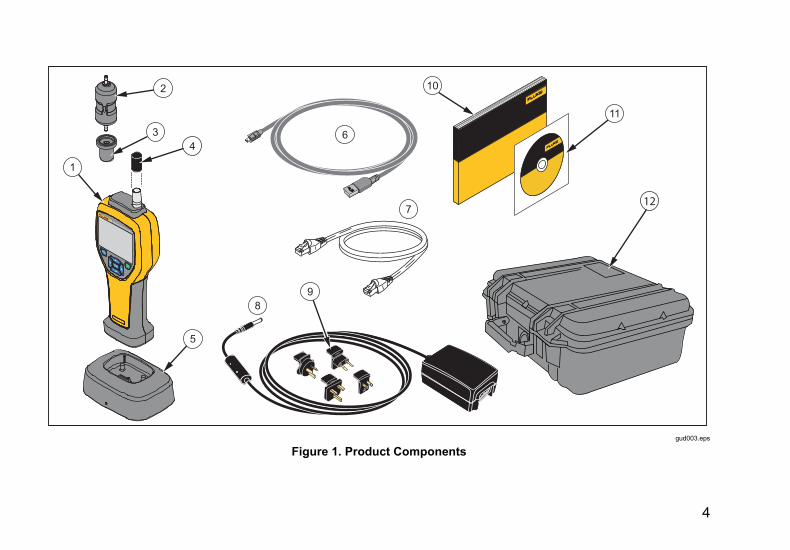
Product Overview This section gives you a brief description of each Product component. See Figure 1 and Table 2 to see the items that are shipped with the Product.
4
1
2
7
89
10
6
12
11
34
5
gud003.eps
Figure 1. Product Components

Airborne Particle Counter Product Overview
5
Table 2. Product Components
Item Description
The Product
Zero-Count Filter
Filter Adapter
Probe Cap
Product Charge Base
USB Cable
Ethernet Cable
AC Adapter
International Power Plug Adapters
985 Getting Started
985 User Manual CD
Product Carrying Case
The Buttons See Table 3 for a description of the Product buttons. For more information on the buttons, see the “Operation” section.
Table 3. Buttons
Button Description
Power- Push to turn the Product ON. Push again and hold for 3 seconds to turn the Product OFF .
Menu- Push to access the Product menus. The Menus are: Sample Screen, Buffered Data Screen, Sample Setup, Communication Setup, and Trend Data. Sample Setup and Communication Setup also have submenus.
Enter/Select- Push to select a menu option. Also use to start and stop a sample when in the Sample Screen.
Navigation- Push to move through the Product menus, menu selections, and to change values.

985 Users Manual
6
Product Connections Power and data connections are on the bottom of the Product and on the rear of the Charge Base. The Ethernet connection is only available on the base. Table 4 and Figure 2 show you the Product connections.
Table 4. Product Connections
Item Description
Power Charge LED
USB Port
Base Input
Flash USB drive Port
Tripod Mount
DC Power Input
32
6
4
5
1
gud001.eps
Figure 2. Product Connections

Airborne Particle Counter Product Overview
7
Charge Base Connections Power and data connections are also on the rear of the Charge Base. The Ethernet connection is only available on the base. Table 5 and Figure 3 show you these connections.
Table 5. Charge Base Connections
Item Description
Ethernet Port
DC Power Input
USB Port
"12V 1.2A
™
321
gud006.eps
Figure 3. Charge Base Connections

985 Users Manual
8
Operation The subsequent sections tell you about Product operation.
Power On/Off Push to turn-on and turn-off the Product.
When the Product is turned on, a splash screen shows, followed by the default sample screen.
You can start to collect samples immediately from the sample screen. The samples use the default or stored sample setup values that you can configure.
Before you use the Product, make sure the battery is fully charged. See “The Battery” section.
Product Test Electrical noise, sensor leakage, or other interference can cause the Product to give incorrect data.
To check operation:
1. Attach the Zero-Count Filter.
2. In the Data Display Setup screen, enable the 0.3 μm channel and set Concentration mode to COUNTS.
3. In the Sample Setup screen:
1. Set the sample time to 5 minutes 2. Set the hold time to 00:00:00 3. Set the delay time to 00:00:03
4. Set the MODE to Automatic 5. Set the number of CYCLES = 2.
4. Start the Product sampling and let it complete the 2 x 5 minute samples.
5. Examine the particle counts from the sample. Counts must align with these specifications for instrument operation to be verified:
No more than 1 particle >0.3 μm in 5 minutes
How to Purge the Product Sensor Particles must be purged (removed) from the Product sensor before use in a clean room or clean environment, and after each high-sampling count. To purge the sensor:
1. Attach the adapter and the Zero-Count Filter.
2. Set the Product to sample continuously (set the Count Mode to Cumulative.)
3. Start the count procedure. Continue the count procedure until there are no new counts.
4. Remove the Zero-Count Filter for normal operation.

Airborne Particle Counter Operation
9
How to Take a Sample Before you take a sample, make sure that you remove the protective cap. To take a sample, select the Sample screen and push . The Product samples with values in the Sample Setup menu. To stop a sample, let the sample procedure complete or push again. See the “Sample Setup Menu” section to set the sample values.
Navigation Menu The navigation menu lets you move through the five different sections of the Product software. To go to the Navigation menu, push . The live navigation icon in the middle of the screen is larger and brighter than the other icons. There are five main menus. See Table 6.The Sample Setup and Communication Setup menus also have submenus. See the “Sample Setup Submenus” section.
Table 6. Main Menu Icons
Icon Menu Item
Sample Screen
Buffered Data Screen
Sample Setup
Communication Setup
Trend Data

985 Users Manual
10
To get in to the navigation menu and select a menu option:
1. Push .
2. Push or to highlight a menu icon. Arrows above and below an icon show that there is a submenu item.
3. Push or to move through the submenus.
4. Push to choose the highlighted icon. The submenu or screen for the selected submenu is shown.
5. Evaluate, edit data, and configure fields as necessary.
Fields and controls in a screen can include radio buttons, text fields, and numeric fields, check boxes and drop down menus. An onscreen keyboard shows when a text field is necessary. Use the keyboard to record data in the field.
Sample Screen Menu The sample screen is the default screen that shows after the Product is turned-on. The screen shows the current sample settings as you take samples. Push or to select from loaded locatons. See Figure 4.
samplescreen.jpg
Figure 4. Sample Screen

Airborne Particle Counter Operation
11
Buffered Data Menu The Product can store 10,000 samples. To see the Buffered Data:
1. Push .
2. Push until the Buffered Data Screen Menu icon shows.
3. Push to see the buffered data samples.
4. To move through each sample, push or . Hold down or to move through the samples faster.
Delete Records From the Buffered Data Screen menu, you can erase all of the samples:
1. Push to highlight .
2. Push .
3. The Product gives you a selection to erase the data.
4. To erase the data, push to highlight and push . All data is erased.
To exit this menu, keep highlighted and push . The Product goes to the buffered data screen.
Setup Menus There are two setup menus:
• Sample Setup
• Communication Setup
Use these menus and their submenus to configure the Product.
Note
In the setup menus there is Help. To access Help, use the Product buttons to highlight and push . An explanation of the setup menu is shown. When completed, push to go back to the previous menu.
Sample Setup Menu To see the primary Sample Setup Menu:
1. Push .
2. Push until the Sample Setup Menu icon shows.
3. Push to go to the Sample Setup screen.
From this menu, you can set the parameters shown in Table 7.

985 Users Manual
12
Table 7. Sample Options
Option Description
Method
Time: The Product samples for the time recorded in this field.
Range: 00:00:01 to 23:59:59. In the Time-based sampling method, this value plus the hold time equals one cycle.
Volume: The Product sample is equal to the volume recorded in this field. In the volume-based sample procedure, this value, plus the hold time, is equal to one cycle. The sample stays at the estimated value.
Hold The time between samples. Range: 00:00:00 to 23:59:59
Delay The time before the first sample starts after is pushed. Range: 00:00:03 to 23:59:59.
Cycles
The total of sample and hold intervals. Range: 0 to 999.
When in Automatic mode, the Product stops after the last cycle is complete. A value of 0 makes the Product run until you push .
Mode
Automatic: the Product samples refer to the recorded parameters.
Manual: the Product samples once and stops.
Beep: Uses Automatic mode settings but ignores count alarm settings. The Product beeps for each particle counted.

Airborne Particle Counter Operation
13
Sample Setup Submenus The Sample Setup Menu includes three submenus. Submenu icons are shown in Table 8 and the subsequent sections tell you about these submenus.
Table 8. Sample Setup Submenus
Icon Submenu Item
Alarm Setup
Data Display Setup
Location Setup
Alarm Setup Submenu The Product Alarm can be set to trigger from different particle dimensions. To update or change a parameter:
1. From the primary Sample Setup Menu icon, push to show the Alarm Setup icon.
2. Push to go into the submenu.
3. You can set the Product Alarm to sound when Particle sizes from 0.3 µm to 10.0 µm.
Use the Product buttons to select and record the menu data.
Data Display Setup Submenu How the Product shows and keeps data can be changed in the Data Display Setup submenu. To update or change a parameter:
1. From the main Sample Setup Menu icon, push twice to show the Data Display Setup icon.
2. Push to go into the submenu.
3. Use the Product buttons to select and record the menu data.
4. Push to configure the parameter.

985 Users Manual
14
The Data Display Setup screen includes check boxes, radio buttons and drop-down menu fields. The Sample screen changes to agree with the display setup.
Parameters such as font size can be different for different configurations.
Setting the Method of Counting Data The choices for data counting are:
Cumulative
Cumulative counting mode includes all particles that are greater than or equal to the particle size selected in the Sample Volume field.
Differential
Differential counting mode includes all particles that are greater than or equal to the particle size selected in the Sample Volume field, but less than the next largest particle size.
Location Setup Submenu Sample location can be recorded for the samples. If the Product is used in multiple areas, it will make the samples clear if the sample location was recorded. 75 locations can be added.
To update or change a location parameter:
1. From the primary Sample Setup Menu icon, push three times to show the Location Setup icon.
2. Push to enter the submenu.
3. Use the Product buttons to choose an action for the location setup. See Table 9.
4. After the location data is changed, push to return to the navigation menu.
Table 9. Location Submenu Icons
Icon Description
Add a location
Edit a location
Delete a location
In the locations, use this to move a selected location down in the list.
In the locations, use this to move a selected location up in the list.

Airborne Particle Counter Operation
15
Communication Setup Submenus The Communication Setup Menu includes two submenus. Submenu icons are shown in Table 10 and the subsequent sections tell you about these submenus.
Table 10. Communication Submenu Icons
Icon Submenu Item
General Setup
Diagnostics
Login
Communication Setup Check DHCP for automatic LAN configuration or uncheck it to set an IP address, Subnet, and Gateway manually.
General Setup Submenu Product hardware setup can be changed with the General Setup submenu. These parameters can be changed:
• Backlight Timeout in seconds: 000 to 999 seconds
• Backlight Contrast: High, Medium, or Low
• Security: You can add a password for the Product. The default password is “123456”. If password is changed and lost, contact Fluke Customer Service to reset it. See the “How to Contact Fluke” section.
• Feedback Volume: Mute, Low, Medium, High
• The Current System Date: MDY, YMD, DMY formats
• The Current System Time: 12 hour or 24 hour
To exit the submenu, push .
Diagnostics Submenu The Diagnostics Submenu shows you static product information:
• Model Number
• Serial Number

985 Users Manual
16
The submenu also shows dynamic data that you can see as a sample is taken:
• Present Battery Voltage
• Calibration: OFF or a voltage during a live sample
• Laser Current: OFF or mA during a live sample
• Motor Current
• Pump Hours (cumulative)
• Laser Hours (cumulative)
• Calibration Date
• Calibration Due Date
At the bottom of the screen, there are these abbreviations, with versions listed:
• FW = firmware
• BL = Bootloader
• FP = FPGA code
• HW = hardware
• BD = Board Dash number
To exit the submenu, push .
Login Submenu
As stated prior, you can lock the General Setup submenu so that the parameter settings cannot be changed.
If the General Setup submenu is locked:
1. Push or to highlight .
2. Push to access the login screen.
3. Enter the password.
The general setup items can now be changed. You can disable password security in the General Setup submenu, but until you disable it, you are still in security mode and it will be necessary for you to enter the password each time you want to go to the General Setup submenu.

Airborne Particle Counter Operation
17
Trend Data
The Product can show you data trends with the Trend Data screen.
Data trends are plotted and graphed in size and count values over time. The graph updates automatically as new data is available. Historical data can also be plotted by location.
To plot particle size data in real time:
1. Push and or to get to the Trend Data icon.
2. Push to enter the Trend Data Screen. The Trend Graph screen is shown.
3. Push .
The Graph Setup screen is shown with the Sampling Control icon active by default.
4. Push to start the sample process with the current setup or change the settings in the Graph Setup screen first, then highlight the Sampling Control icon and push . The sample process starts.
Note
Refer to the Help screen for more information about Graph Setup.
The right side of the trend graph is fixed at the most recent sample. Push to adjust the number of sample points displayed in the trend graph. The maximum number of samples displayed is 255. Use and to adjust the Y axis scale.
Note
If historical location data is selected for review at the Trend setup screen, the x-axis will only be linear if the sample times of each of the data records are the same.

985 Users Manual
18
Data Export The Product stores collected data in flash memory. The data is stored until the data is cleared and is retained when the Product is off. Data can be moved to a PC or laptop with a USB cable, a flash USB drive, or transmitted through an Ethernet connection. A sample report, seen in Excel, is shown in Figure 5.
How to Move Product Data to a PC with a USB Cable To move Product data to a PC with a USB cable:
1. Connect the USB cable to the Product or the Charge Base USB port. If you use the Charge Base, the Product must be on the base. See the “Product Connections” and “Charge Base Connections” sections. When you connect the USB cable, you will
see .
2. Use Windows Explorer to go to the HPC USB Drive.
3. Windows Explorer will open and show you the Data.tsv file icon. Right click on the file and open it with Excel or a text editor. A sample report, seen in Excel, is shown in Figure 5.
How to Move Product Data to a Flash USB Drive To move Product data to a flash USB drive:
1. Connect the USB flash drive to the Product USB drive port. See Figure 2. When you connect the USB drive, wait for the USB drive icon ( ) to show at the bottom of the display.
2. Push and go to the Buffered Data Screen.
3. Push .
4. Push to highlight the data export icon ( ).
5. Push to export the data to the flash USB drive.
To see the data:
1. Use Windows Explorer to go to the flash USB drive.
2. On the drive, there will be a Data.tsv file. Double click the file open it. The file can be opened with a text editor or Microsoft Excel. A sample report, seen in Excel, is shown in Figure 5. Note that each time you download data to the drive, previously downloaded data is overwritten.

Airborne Particle Counter Data Export
19
How to Move Product Data with an Ethernet Cable To move Product data to a PC with an Ethernet cable, you can connect the Ethernet cable to the PC or directly to an Ethernet connection source.
If you connect directly to the PC Ethernet port, you must be able to connect to the network, for example, with a wireless connection. With this setup, the Product IP address and subnet will need to be set manually.
1. The Charge Base must be used for Ethernet connectivity. Connect the Ethernet cable to the Charge Base Ethernet port and to the Ethernet source. The Product must be on the base. See the “Charge Base Connections” section.
When the Ethernet cable is connected, you will see the Ethernet connection icon on the lower display ( ).
2. With a web browser, go to the internet address HPC[Product Serial Number]. After “HPC” add your Product serial number without brackets. A website where you can download the Data.tsv file to your PC opens.
3. Double click on the filename to download or open the file.
To see the data:
1. If the file was downloaded, use Windows Explorer to go to the directory where the file was downloaded. If you choose to open the file from the web browser, go to step 2.
2. Double-click the file open it. The file can be opened with a text editor or Microsoft Excel. A sample report, seen in Excel, is shown in Figure 5.

985 Users Manual
20
report.jpg
Figure 5. Exported Data

Airborne Particle Counter Maintenance
21
Maintenance
Warning
To prevent possible electrical shock, fire, or personal injury: • Have an approved technician repair the
Product.
• Use only specified replacement parts.
• Do not put battery cells and battery packs near heat or fire. Do not put in sunlight.
• Do not disassemble or crush battery cells and battery packs.
For safe operation and maintenance of the product:
• Repair the Product before use if the battery leaks.
• Connect the battery charger to the mains power outlet before the Product.
• Do not keep cells or batteries in a container where the terminals can be shorted.

985 Users Manual
22
Specifications General Particle-Size Range ....................................... (0.3, 0.5, 1.0, 2.0, 5.0, 10.0) µm
Channels ....................................................... 6
Flow Rate ...................................................... 0.1 cfm (2.83 L/min)
Light Source .................................................. 775 nm to 795 nm, 90 mW class 3B laser
Calibration ..................................................... PSL particles in air (NIST traceable)
Counting Efficiency ........................................ 50 % @ 0.3 µm; 100 % for particles >0.45 µm (per ISO 21501)
Zero Count Level ........................................... 1 count / 5 minute (per JIS B9921)
Concentration Limits ...................................... 10 % at 4,000,000 per cubic ft (per ISO 21501)
Count Mode ................................................... raw counts, #/ft3, #/m3, #/l in cumulative or differential mode
Data Storage ................................................. 10,000 records (rotating buffer)
Delay Time .................................................... 0 hours to 24 hours
Sample Inlet ................................................... Isokinetic Probe
Security .......................................................... Adminstrator password controlled (optional)
Communication Modes .................................. USB or Ethernet
Display .......................................................... QVGA color with backlight
Alarms ........................................................... User defined for each particle size
Dimensions .................................................... (27.2 x 9.9 x 5.3) cm (10.7 x 3.9 x 2.1) inches

Airborne Particle Counter Specifications
23
Weight ........................................................... 680.39 g (1.5 lb)
Environmental IP Rating ....................................................... 40
Operating Humidity........................................ <95 % RH non-condensing
Protection Class ............................................ Pollution Degree 2
Operating Temperature ................................. 10 °C to 40 °C (50 °F to 104 °F)
Operating Altitude.......................................... up to 6000 ft. ASL
Storage Humidity ........................................... up to 98 % RH non-condensing
Storage Temperature .................................... -10 °C to 50 °C (14 °F to 122 °F)
Power ............................................................ AC Adapter, 100 to 240 Vac, 12 Vdc, 2.5 A
Battery Type .................................................. LI-Ion 7.4 V, 2600 mAh
Charge time ................................................... 3.5 hours
Battery Duration ............................................ 5 hours continuous sampling. 10 hours with typical use model.
Agency Approvals ......................................... ,

985 Users Manual
24


![[Welding] Miller Buyer's Guide; Plasma Cutting Buyer's Handbook (eBook, 20 Pages)](https://static.fdocuments.in/doc/165x107/55cf9a94550346d033a2702a/welding-miller-buyers-guide-plasma-cutting-buyers-handbook-ebook.jpg)