Air Vents - EMES · Air Vent ID Charts Table AV-316-1. Armstrong Air Vents Illustration Type Flow...
22
Air Vents
Transcript of Air Vents - EMES · Air Vent ID Charts Table AV-316-1. Armstrong Air Vents Illustration Type Flow...

Air Vents

Air Vents
ProvenSame proven, free-floating allstainless steel mechanism asused in Armstrong steamtraps.
High pressureArmstrong air/gas vents canhandle applications to 186 bar.
Leak-tightPositive closing, free-floatingstainless steel lever ensures
leak-tight closing under allconditions.
Body optionsVariety of body materials
available: polysulfone, castiron, forged steel and all
stainless steel. A materialfor every application.
Armstrong International SA • Parc Industriel des Hauts-Sarts (2e Avenue) • 4040 Herstal • BelgiumTel.: +32 (0)4 240 90 90 • Fax: +32 (0)4 248 13 61
www.armstrong.be • [email protected]
Air
Vent
s

With the desired capacity in m³/h known, find the orifice sizerequired from the table on this page. Then find the vent or ventswith the correct orifice size on pages AV-318 to AV-327 that willoperate at the required pressure with a liquid of the specificgravity being handled.
Example – Find a model number that will vent 88,3 m³/h of air(including safety factor of 1,5 - 2,0) from a liquid with a specificgravity of 0,93 at 17 bar. Using the table below, follow the 17bar line across to the number 103. Orifice size is 5/32". Now goto pages AV-318 to AV-327 checking the 5/32" orifice lines tolocate a vent for 17 bar or higher with 0,90 gravity liquid.
Note: Since specific gravity falls between 0,95 and 0,90, use0,90 gravity data. The model 3-AV on page AV-320 is the one touse.
For Venting During Filling OnlyIf a vent is required only for getting rid of air when a system isstarted up, such as when starting up a deep well pump or fillingan empty pipe, tank or other vessel, ability of the vent to openat operating pressure can be ignored. In these cases, a modelnumber with a large orifice for fast venting may be selected, butthe vent will not open after air is expelled and the systemreaches operating pressure.
Selecting The Armstrong Air/Gas Vent
Table AV-315-1. Discharge of Air Through an Orifice in m³/h at a Standard Atmospheric Pressure of 1 bar(a) and 21°C
Pressurebarg
Orifice Diameter, inch
1/16" 5/64" 3/32" #38 7/64" 1/8" 9/64" 5/32" 3/16" 7/32" 1/4" 9/32" 5/16" 11/32" 3/8" 7/16" 1/2" 9/16" 5/8" 3/4" 7/8" 1 1/16"0,3 1,10 1,72 2,46 2,63 3,36 4,38 5,56 6,85 9,87 13,4 17,5 22,3 27,4 33,1 39,4 53,7 70,2 88,9 110 158 214 3160,4 1,21 1,87 2,70 2,89 3,67 4,79 6,07 7,49 10,8 14,7 19,2 24,3 29,9 36,2 43,2 58,6 76,6 97,0 120 173 234 3470,5 1,29 2,02 2,91 3,11 3,96 5,16 6,54 8,07 11,6 15,8 20,7 26,2 32,3 39,1 46,4 63,2 82,6 104 129 185 253 3740,6 1,46 2,28 3,28 3,52 4,47 5,83 7,37 9,11 13,1 17,8 23,3 29,6 36,4 44,0 52,5 71,4 93,3 118 146 209 285 4210,8 1,67 2,62 3,75 4,03 5,11 6,68 8,46 10,4 15,0 20,4 26,7 33,8 41,8 50,5 60,1 81,9 107 135 167 241 328 483
1,0 1,85 2,91 4,18 4,47 5,67 7,42 9,40 11,6 16,7 22,8 29,7 37,5 46,4 56,1 66,8 90,9 119 150 185 267 364 5371,4 2,12 3,31 4,77 5,11 6,49 8,48 10,7 13,3 19,0 26,0 34,0 43,0 53,0 64,1 76,3 104 136 172 212 306 416 6131,7 2,34 3,67 5,28 5,66 7,19 9,40 11,9 14,7 21,1 28,7 37,5 47,6 58,6 71,0 84,4 115 150 190 234 338 460 6782,0 2,62 4,08 5,88 6,29 8,00 10,4 13,2 16,3 23,4 31,9 41,8 52,8 65,2 79,0 94,0 128 167 212 262 375 511 7542,4 2,94 4,60 6,63 7,08 9,02 11,8 14,9 18,3 26,5 36,0 47,1 59,6 73,6 89,0 106 144 189 238 294 425 578 851
2,8 3,28 5,11 7,37 7,88 10,0 13,1 16,6 20,4 29,4 40,1 52,3 66,3 81,9 99,1 118 160 209 265 328 471 642 9463,1 3,60 5,62 8,10 8,66 11,0 14,4 18,2 22,4 32,5 44,2 57,6 72,9 90,0 109 130 177 231 292 360 518 705 1 0403,5 3,92 6,13 8,83 9,45 12,0 15,7 19,9 24,5 35,3 48,1 62,9 79,5 98,0 119 141 192 251 318 392 566 770 1 1334,1 4,57 7,14 10,3 11,0 14,0 18,3 23,1 28,5 41,1 55,9 73,1 92,4 114 138 164 224 292 370 457 658 895 1 3204,8 5,20 8,14 11,7 12,5 16,0 20,9 26,3 32,6 46,9 63,7 83,3 106 130 157 187 255 333 421 520 749 1 021 1 505
5,5 5,84 9,12 13,2 14,1 17,8 23,4 29,6 36,5 52,7 71,5 93,4 118 146 177 211 287 374 474 584 841 1 145 1 6896,2 6,47 10,1 14,6 15,6 19,9 26,0 32,8 40,4 58,3 79,3 104 131 162 195 233 318 415 525 647 933 1 269 1 8727,0 7,12 11,1 16,0 17,2 21,7 28,4 36,0 44,5 64,1 87,2 114 144 178 216 257 348 455 576 712 1 025 1 393 2 0567,6 7,75 12,1 17,5 18,7 23,8 30,9 39,2 48,4 69,7 94,8 124 157 194 234 279 379 496 627 775 1 115 1 517 2 2388,5 8,68 13,6 19,5 20,9 26,7 34,8 44,0 54,4 78,2 107 139 177 217 263 313 426 556 703 868 1 252 1 704 2 511
10 10,3 16,0 23,1 24,8 31,4 41,1 52,0 64,2 92,4 126 164 207 257 311 369 503 658 831 1 026 1 478 2 012 2 96614 13,4 20,9 30,2 32,3 41,1 53,7 68,0 83,8 121 164 214 272 335 406 483 658 858 1 086 1 341 1 930 2 628 3 87517 16,5 25,8 37,2 39,9 50,6 66,3 83,8 103 149 202 265 335 413 501 596 810 1 058 1 341 1 655 2 382 3 243 4 78120 19,7 30,8 44,3 47,4 60,3 78,7 99,6 123 177 241 314 399 493 595 708 965 1 259 1 594 1 967 2 834 3 858 5 68828 26,0 40,6 58,4 62,5 79,5 104 131 162 233 318 415 525 649 785 934 1 271 1 662 2 255 2 594 3 736 5 087 7 499
35 32,3 50,3 72,5 77,6 98,7 129 163 202 291 394 515 652 805 975 1 160 1 578 2 063 2 610 3 221 4 640 6 315 9 31141 38,4 60,1 86,6 92,8 118 154 195 241 347 471 615 780 962 1 164 1 385 1 886 2 464 3 118 3 848 5 540 7 542 11 12252 47,9 74,8 108 115 147 192 243 299 432 586 766 970 1 196 1 448 1 723 2 346 3 063 3 879 4 788 6 895 9 384 13 83769 63,5 99,2 143 153 195 255 321 398 573 778 1 016 1 286 1 589 1 992 2 287 3 113 4 066 5 146 6 354 9 149 12 452 18 361
Armstrong International SA • Parc Industriel des Hauts-Sarts (2e Avenue) • 4040 Herstal • BelgiumTel.: +32 (0)4 240 90 90 • Fax: +32 (0)4 248 13 61
www.armstrong.be • [email protected] AV-315
Air Vents
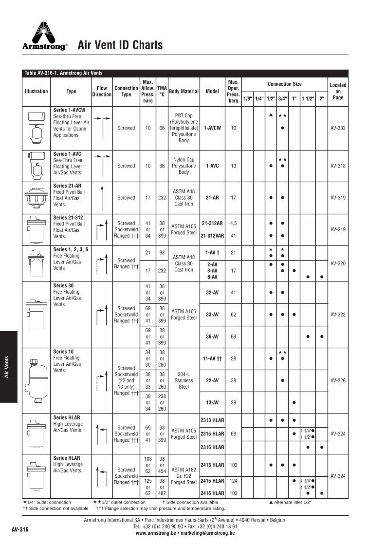
Air Vent ID Charts
Table AV-316-1. Armstrong Air Vents
Illustration Type FlowDirection
ConnectionType
Max.Allow.Press.barg
TMA°C Body Material Model
Max.Oper.Press.barg
Connection Size Locatedon
Page1/8" 1/4" 1/2" 3/4" 1" 1 1/2" 2"
Series 1-AVCWSee-thru FreeFloating Lever AirVents for OzoneApplications
Screwed 10 66
PBT Cap(PolybutyleneTerephthalate)Polysulfone
Body
1-AVCW 10
▲ ��
� AV-332
Series 1-AVCSee-Thru FreeFloating LeverAir/Gas Vents
Screwed 10 66Nylon Cap
PolysulfoneBody
1-AVC 10 �
��
� AV-318
Series 21-ARFixed Pivot BallFloat Air/GasVents
Screwed 17 232ASTM A48Class 30Cast Iron
21-AR 17 � � AV-319
Series 21-312Fixed Pivot BallFloat Air/GasVents
ScrewedSocketweldFlanged †††
41or34
38or
399
ASTM A105Forged Steel
21-312AR
21-312VAR
4,5
41
�
�
�
�
AV-319
Series 1, 2, 3, 6Free FloatingLever Air/GasVents
ScrewedFlanged †††
21 93ASTM A48Class 30Cast Iron
1-AV † 21 �
�
�
�
AV-32017 232
2-AV3-AV6-AV
17� �
� �
� �
Series 30Free FloatingLever Air/GasVents
ScrewedSocketweldFlanged †††
41or34
38or
399
ASTM A105Forged Steel
32-AV 41 � �
AV-32269or41
38or
39933-AV 62 � � �
69or41
38or
39936-AV 69 � �
Series 10Free FloatingLever Air/GasVents Screwed
Socketweld(22 and13 only)
Flanged †††
34or30
38or
260
304-LStainless
Steel
11-AV †† 28 �
��
�
AV-32638or33
38or
26022-AV 38 �
39or34
238or
26013-AV 39 �
Series HLARHigh LeverageAir/Gas Vents Screwed
SocketweldFlanged †††
69or41
38or
399
ASTM A105Forged Steel
2313 HLAR
69
� � �
AV-3242315 HLAR ��
�
2316 HLAR � �
Series HLARHigh LeverageAir/Gas Vents Screwed
SocketweldFlanged †††
103or62
38or
454 ASTM A182Gr. F22
Forged Steel
2413 HLAR 103 � � �
AV-324125or62
38or
482
2415 HLAR
2416 HLAR
124
103
� �
�
� �
�1/4" outlet connection ��1/2" outlet connection † Side connection available ▲ Alternate inlet 1/2"†† Side connection not available ††† Flange selection may limit pressure and temperature rating.
1 1/4"1 1/2"
1 1/4"1 1/2"
Armstrong International SA • Parc Industriel des Hauts-Sarts (2e Avenue) • 4040 Herstal • BelgiumTel.: +32 (0)4 240 90 90 • Fax: +32 (0)4 248 13 61
www.armstrong.be • [email protected]
Air
Vent
s

Air Vent ID Charts
1 1/4"
1 1/4"
�1/4" outlet connection ��1/2" outlet connection † Side connection available ▲ Alternate inlet 1/2"†† Side connection not available ††† Flange selection may limit pressure and temperature rating.All models comply with the Pressure Equipment Directive PED 97/23/EC. For details, see specific product page or Armstrong PED Certificate.
Table AV-317-1. Armstrong Air Vents
Illustration Type FlowDirection
ConnectionType
Max.Allow.Press.barg
TMA°C
BodyMaterial Model
Max.Oper.Press.barg
Connection Size Locatedon
Page1/8" 1/4" 1/2" 3/4" 1" 1 1/2" 2"
Series HLARHighLeverageAir/Gas Vents
ScrewedSocketweldFlanged †††
146or
117
38or
482
ASTM A182Gr. F22
Forged Steel
25133G-HLAR 146 � � �
AV-324174or
138
38or
482
15155G-HLAR 172 � � �
255or
207
38or
482
16155G-HLAR 186 � �
Series TTFThermostaticAir Vents Straight-Thru
Right Angle 20 232 304-LStainless Steel
TTF-1
TTF-1R21 � � AV-328
TAVBThermostaticBellows withIntegralVacuumBreaker
Straight-ThruScrewed 20 232 304L
Stainless Steel
TAVB-2
10
�
AV-329
TAVB-3 �
Series TV-2ThermostaticAir Vents Screwed 9 177 ASTM B62
Cast Bronze TV-2 8,5 � AV-331
Series TS-2ThermostaticAir Vents Threaded 3,5 149 ASTM B62
Bronze TS-2 3,5 � � AV-330
AV-11, AV-13HydronicSystem AirVents Screwed
3,5
1099 Brass
AV-11
AV-13
3,5
10� � � AV-333
Armstrong International SA • Parc Industriel des Hauts-Sarts (2e Avenue) • 4040 Herstal • BelgiumTel.: +32 (0)4 240 90 90 • Fax: +32 (0)4 248 13 61
www.armstrong.be • [email protected] AV-317
Air Vents

1-AVC See-Thru Air VentFor Pressures to 10 bar or Specific Gravity Down to 0,80
A See-Thru Body – So You’ll Know When It’s WorkingNow, you can literally see what you’ve been missing – the earlywarning signs of a system problem. Since you’ll know theoperating condition of the air vent, you won’t have to waste timeand money scheduling maintenance that isn’t needed. In otherwords, you will be able to react to a condition before it becomesa problem.
A simple ball float mechanism requiring no electricity to operate,the new Armstrong 1-AVC discharges automatically only whenair/gas are present. That means no liquid loss as with manualventing.
An Inside LookSee-thru body means you can observe changing conditions asthey occur. See a problem in the making – instead of having todeal with it after the fact.
Efficient OperationSimple ball float mechanism discharges only when air ispresent so it doesn’t waste liquid.
Positive SeatingFree-floating valve mechanism assures positive seating so itprevents liquid loss. There are no fixed pivots to wear or createfriction, and wear points are heavily reinforced for long life.
Reduced MaintenanceStainless steel internals mean corrosion resistance and reducedmaintenance.
Corrosion ResistanceLong-lasting polysulfone body and reinforced nylon cap resistcorrosion and provide long, trouble-free service life.
Compare… and Save the DifferenceSeeing is really believing – especially when you compare theArmstrong see-thru air vent with manual venting. Measure thedifferences in the time and money you can save with a moreefficient, easier-to-maintain system. For more information ortechnical assistance, contact your local ArmstrongRepresentative.
Note: The Armstrong 1-AVC should not be used in anenvironment where there are high levels of ketones orchlorinated or aromatic hydrocarbons.
1-AVC
Table AV-318-1. 1-AVC List of MaterialsName of Part Material
Cap Reinforced NylonBody Polysulfone*O-Rings (Body Cap and Fitting) Nitrile Elastome CompoundFloat Lever and Screws Stainless SteelValve & Seat Stainless SteelFitting & Pipe Plug Reinforced NylonRetainer Ring Zinc Plated Steel
Table AV-318-2. 1-AVC Physical Datamm
Inlet Connection 15 – 20Outlet Connection 15“A” Face-to-Face 89“B” Height 171“C” Bottom to C 152Maximum Allowable Pressure (Vessel Design) 10 bar @ 65°CMaximum Operating Pressure 10 barSpecific Gravity Range 1,00 to 0,80Weight in kg (screwed) 0,45
Table AV-318-3. 1-AVC CapacityDifferential Pressure
Orifice size (in) m³/hbar1,0
1/8"
7,32,0 11,03,5 16,15,0 22,27,0 28,78,5 34,810,0 41,1
AlternateInlet
Outlet
Inlet
* UV sensitive.
Note: Discharge of air through an orifice in m³/h at a standard atmosphericpressure of 1 bar(a) and 21°C.
L
All sizes comply with the article 3.3 of the PED (97/23/EC).
Armstrong International SA • Parc Industriel des Hauts-Sarts (2e Avenue) • 4040 Herstal • BelgiumTel.: +32 (0)4 240 90 90 • Fax: +32 (0)4 248 13 61
www.armstrong.be • [email protected]
Air
Vent
s
All dimensions and weights are approximate. Use certified print for exact dimensions. Design and materials are subject to change without notice.
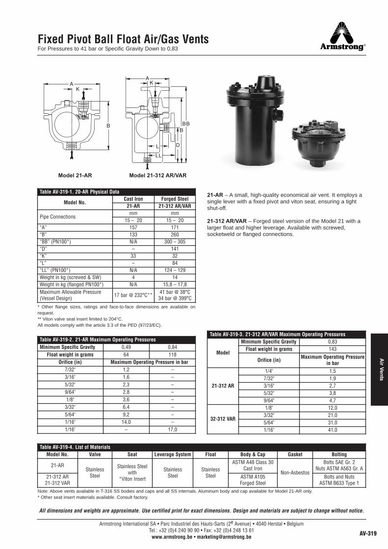
Fixed Pivot Ball Float Air/Gas VentsFor Pressures to 41 bar or Specific Gravity Down to 0,83
21-AR – A small, high-quality economical air vent. It employs asingle lever with a fixed pivot and viton seat, ensuring a tightshut-off.
21-312 AR/VAR – Forged steel version of the Model 21 with alarger float and higher leverage. Available with screwed,socketweld or flanged connections.
Note: Above vents available in T-316 SS bodies and caps and all SS internals. Aluminum body and cap available for Model 21-AR only.* Other seat insert materials available. Consult factory.
* Other flange sizes, ratings and face-to-face dimensions are available onrequest.** Viton valve seat insert limited to 204°C.All models comply with the article 3.3 of the PED (97/23/EC).
Model 21-AR Model 21-312 AR/VAR
Table AV-319-1. 20-AR Physical Data
Model No.Cast Iron Forged Steel
21-AR 21-312 AR/VAR
Pipe Connectionsmm mm
15 – 20 15 – 20“A” 157 171“B” 133 260“BB” (PN100*) N/A 300 – 305“D” – 141“K” 33 32“L” – 84“LL” (PN100*) N/A 124 – 129Weight in kg (screwed & SW) 4 14Weight in kg (flanged PN100*) N/A 15,8 – 17,8Maximum Allowable Pressure(Vessel Design) 17 bar @ 232°C** 41 bar @ 38°C
34 bar @ 399°C
Table AV-319-2. 21-AR Maximum Operating PressuresMinimum Specific Gravity 0,49 0,84
Float weight in grams 64 118Orifice (in) Maximum Operating Pressure in bar
7/32" 1,2 –3/16" 1,6 –5/32" 2,3 –9/64" 2,8 –1/8" 3,6 –3/32" 6,4 –5/64" 9,2 –1/16" 14,0 –1/16" – 17,0
Table AV-319-3. 21-312 AR/VAR Maximum Operating Pressures
Model
Minimum Specific Gravity 0,83Float weight in grams 143
Orifice (in) Maximum Operating Pressurein bar
21-312 AR
1/4" 1,57/32" 1,93/16" 2,75/32" 3,89/64" 4,7
32-312 VAR
1/8" 12,03/32" 21,05/64" 31,01/16" 41,0
Table AV-319-4. List of MaterialsModel No. Valve Seat Leverage System Float Body & Cap Gasket Bolting
21-ARStainless
Steel
Stainless Steelwith
*Viton Insert
StainlessSteel
StainlessSteel
ASTM A48 Class 30Cast Iron
Non-Asbestos
Bolts SAE Gr. 2Nuts ASTM A563 Gr. A
21-312 AR21-312 VAR
ASTM A105Forged Steel
Bolts and NutsASTM B633 Type 1
Armstrong International SA • Parc Industriel des Hauts-Sarts (2e Avenue) • 4040 Herstal • BelgiumTel.: +32 (0)4 240 90 90 • Fax: +32 (0)4 248 13 61
www.armstrong.be • [email protected] AV-319
Air Vents
All dimensions and weights are approximate. Use certified print for exact dimensions. Design and materials are subject to change without notice.

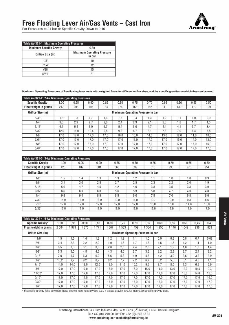
Free Floating Lever Air/Gas Vents – Cast IronFor Pressures to 21 bar or Specific Gravity Down to 0,40
Armstrong free floating lever Air/Gas Vents use the samebodies, caps, lever mechanisms, valves and seats of Armstronginverted bucket steam traps that have been proven in years ofservice.
Elliptical floats and high leverage make it possible to open largeorifices to provide adequate capacity for vent size and weight.The hemispherical valve, seat and leverage are identical indesign, materials and workmanship to those for saturatedsteam service up to 69 bar, with the exception of the addition ofa guidepost to assure a positive, leaktight valve closing underall conditions.
1-AV – A cast iron air vent that uses a positive-closing freefloating lever to ensure leaktight closing under all conditions.This vent is good for low capacity air/gas venting up to 21 bar.
2-AV, 3-AV and 6-AV – Cast iron vents using the same provenfree floating lever mechanisms used in Armstrong steam traps.For applications where high air/gas venting capacity is requiredup to 17 bar.
Model 1-AV Model 2-AV, 3-AV and 6-AV
Table AV-320-1. Physical Data
Model No.Cast Iron
1-AV** 2-AV 3-AV 6-AV
Pipe Connectionsmm mm mm mm
15* – 20* 15 – 20 20 – 25 40 – 50“A” 89 133 162 259“B” 140 203 273 432“BB” (PN40***) N/A 320 – 330 400 – 392 562 – 568“D” – 111 155 213“K” 21 – – –“L” – 62 73 123“LL” (PN40***) N/A 179 – 189 203 – 195 180 – 186Weight in kg (screwed) 1,8 6 10 36Weight in kg (flanged PN40***) N/A 8,7 – 9,6 13,6 – 14,2 42,6 – 45,0Maximum Allowable Pressure(Vessel Design)
21 bar @ 93°C17 bar @ 232°C 17 bar @ 232°C 17 bar @ 232°C 17 bar @ 232°C
Table AV-320-2. List of MaterialsModel No. Valve & Seat Leverage System Float Body & Cap Gasket Bolts Nuts
1-AV
Stainless SteelASTM A48Class 30Cast Iron
Non-asbestos
ASTM A193 Gr. B7ASTM A563
Gr. A2-AV
SAE Gr. 23-AV6-AV
* Outlet connection 1/4". ** 1-AV available with side connection if specified on order. On models 2-AV, 3-AV and 6-AV, pipe size of side connections is same as that of inlet and outletconnections. Some floats are oil filled. Consult factory for details.*** Other flange sizes, ratings and face-to-face dimensions are available on request.Shade indicates products that are CE Marked according to the PED (97/23/EC). All the other models comply with the Article 3.3 of the same directive.
Armstrong International SA • Parc Industriel des Hauts-Sarts (2e Avenue) • 4040 Herstal • BelgiumTel.: +32 (0)4 240 90 90 • Fax: +32 (0)4 248 13 61
www.armstrong.be • [email protected]
Air
Vent
s
All dimensions and weights are approximate. Use certified print for exact dimensions. Design and materials are subject to change without notice.
Free Floating Lever Air/Gas Vents – Cast IronFor Pressures to 21 bar or Specific Gravity Down to 0,40
* If specific gravity falls between those shown, use next lowest: e.g., if actual gravity is 0,73, use 0,70 specific gravity data.
Table AV-321-1. Maximum Operating PressuresMinimum Specific Gravity 0,80
Orifice Size (in) Maximum Operating Pressurein bar
1/8" 107/64" 12#38 15
5/64" 21
Table AV-321-2. 2-AV Maximum Operating PressuresSpecific Gravity* 1,00 0,95 0,90 0,85 0,80 0,75 0,70 0,65 0,60 0,55 0,50
Float weight in grams 217 206 195 184 174 163 152 141 130 119 109
Orifice Size (in) Maximum Operating Pressure in bar
5/46" 1,8 1,8 1,7 1,6 1,5 1,4 1,3 1,2 1,1 1,0 0,91/4" 3,0 2,9 2,7 2,6 2,4 2,3 2,1 2,0 1,8 1,7 1,53/16" 6,7 6,4 6,0 5,7 5,4 5,0 4,7 4,4 4,1 3,7 3,45/32" 12,0 11,0 10,4 9,8 9,3 8,7 8,1 7,6 7,0 6,4 5,81/8" 17,0 17,0 17,0 17,0 16,0 15,0 14,0 13,0 12,0 11,0 10,07/64" 17,0 17,0 17,0 17,0 17,0 17,0 17,0 17,0 15,0 14,0 13,0#38 17,0 17,0 17,0 17,0 17,0 17,0 17,0 17,0 17,0 17,0 16,0
5/64" 17,0 17,0 17,0 17,0 17,0 17,0 17,0 17,0 17,0 17,0 17,0
Table AV-321-3. 3-AV Maximum Operating PressuresSpecific Gravity 1,00 0,95 0,90 0,85 0,80 0,75 0,70 0,65 0,60
Float weight in grams 423 402 381 360 339 318 296 275 254
Orifice Size (in) Maximum Operating Pressure in bar
1/2" 1,5 1,4 1,3 1,3 1,2 1,1 1,0 1,0 0,93/8" 3,1 3,0 2,8 2,7 2,5 2,3 2,2 2,0 1,95/16" 5,0 4,7 4,5 4,2 4,0 3,8 3,5 3,3 3,09/32" 6,6 6,3 6,0 5,6 5,3 5,0 4,7 4,3 4,01/4" 9,9 9,4 8,9 8,5 8,0 7,5 7,0 6,5 6,07/32" 14,0 13,0 13,0 12,0 11,0 10,7 10,0 9,3 8,63/16" 17,0 17,0 17,0 17,0 17,0 16,0 15,0 14,0 13,05/32" 17,0 17,0 17,0 17,0 17,0 17,0 17,0 17,0 17,0
Table AV-321-4. 6-AV Maximum Operating PressuresSpecific Gravity* 1,00 0,95 0,90 0,85 0,80 0,75 0,70 0,65 0,60 0,55 0,50 0,45 0,40
Float weight in grams 2 084 1 979 1 875 1 771 1 667 1 563 1 459 1 354 1 250 1 146 1 042 938 833
Orifice Size (in) Maximum Operating Pressure in bar
1 1/6" 1,5 1,5 1,4 1,3 1,2 1,2 1,1 1,0 0,9 0,8 0,8 0,7 0,627/8" 2,4 2,3 2,2 2,0 1,9 1,8 1,7 1,6 1,5 1,3 1,2 1,1 1,03/4" 3,5 3,3 3,1 3,0 2,8 2,6 2,4 2,3 2,1 1,9 1,8 1,6 1,45/8" 5,3 5,0 4,8 4,5 4,3 4,0 3,7 3,5 3,2 2,9 2,7 2,4 2,29/16" 7,0 6,7 6,3 6,0 5,6 5,3 4,9 4,6 4,2 3,9 3,6 3,2 3,91/2" 10,2 9,7 9,2 8,7 8,2 7,7 7,2 6,7 6,2 5,6 5,1 4,6 4,17/16" 14,0 14,0 13,0 12,0 12,0 11,0 10,2 9,5 8,7 8,0 7,3 6,6 5,93/8" 17,0 17,0 17,0 17,0 17,0 17,0 16,0 15,0 14,0 13,0 12,0 10,4 9,3
11/32" 17,0 17,0 17,0 17,0 17,0 17,0 17,0 17,0 17,0 17,0 15,0 14,0 12,05/16" 17,0 17,0 17,0 17,0 17,0 17,0 17,0 17,0 17,0 17,0 17,0 17,0 16,09/32" 17,0 17,0 17,0 17,0 17,0 17,0 17,0 17,0 17,0 17,0 17,0 17,0 17,01/4" 17,0 17,0 17,0 17,0 17,0 17,0 17,0 17,0 17,0 17,0 17,0 17,0 17,0
Maximum Operating Pressures of free floating lever vents with weighted floats for different orifice sizes, and the specific gravities on which they can be used.
Armstrong International SA • Parc Industriel des Hauts-Sarts (2e Avenue) • 4040 Herstal • BelgiumTel.: +32 (0)4 240 90 90 • Fax: +32 (0)4 248 13 61
www.armstrong.be • [email protected] AV-321
Air Vents

Free Floating Lever Air/Gas Vents – Forged SteelFor Pressures to 69 bar or Specific Gravity Down to 0,40
32-AV, 33-AV and 36-AV – Forged steel vents using the sameproven free floating lever mechanisms used in Armstrong steamtraps.
For applications where high air/gas venting capacity is requiredup to 69 bar. Available with screwed, socketweld or flangedconnections.
Model 32-AV, 33-AV and 36-AV
Table AV-322-1. 30-AV Series List of MaterialsModel No. Valve & Seat Leverage System Float Body & Cap Gasket Bolting
32-AVStainless Steel ASTM A105
Forged Steel Non-asbestos Bolts ASTM A193 Gr. B7Nuts ASTM A194 Gr. 2H33-AV
36-AV
Table AV-322-2. 30-AV Series Physical Data
Model No.Forged Steel
32-AV † 33-AV † 36-AV †Pipe Connections 15 – 20 20 – 25 40 – 50“A” 171 203 301“B” 259 295 435“BB” (PN100*) 300 – 305 343 – 349 – 355 500 – 505“D” 141 154 229“K” 32 37 54“L” 86 98 154“LL” (PN100*) 127 – 132 145 – 153 – 159 198 – 204Weight in kg (screwed & SW) 14 22 74Weight in kg (flanged PN100*) 15,8 – 17,8 25,0 – 26,0 83,2 – 87,2
Maximum Allowable Pressure(Vessel Design)
41 bar @ 38°C34 bar @ 399°C
69 bar @ 38°C41 bar @ 399°C
† Available in Type 316 SS. Consult factory. Pipe size of side connections if provided is same as that of inlet and outlet connections. Some floats are oil filled.Consult factory for details.
* Other flange sizes, ratings and face-to-face dimensions are available on request.Shade indicates products that are CE Marked according to the PED (97/23/EC). All the other models comply with the Article 3.3 of the same directive.
Armstrong International SA • Parc Industriel des Hauts-Sarts (2e Avenue) • 4040 Herstal • BelgiumTel.: +32 (0)4 240 90 90 • Fax: +32 (0)4 248 13 61
www.armstrong.be • [email protected]
Air
Vent
s
All dimensions and weights are approximate. Use certified print for exact dimensions. Design and materials are subject to change without notice.
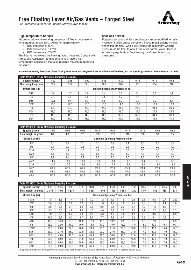
Free Floating Lever Air/Gas Vents – Forged SteelFor Pressures to 69 bar or Specific Gravity Down to 0,40
High-Temperature ServiceMaximum allowable working pressures of floats decrease attemperatures above 38°C. Allow for approximately:
• 10% decrease at 93°C• 15% decrease at 147°C• 20% decrease at 204°C
The float is not always the limiting factor, however. Consult withArmstrong Application Engineering if you have a high-temperature application that also requires maximum operatingpressures.
Sour Gas ServiceForged steel and stainless steel traps can be modified to resisthydrogen sulfide stress corrosion. These modifications involveannealing the float, which will reduce the maximum workingpressure of the float to about half of its normal value. ConsultArmstrong Application Engineering for allowable workingpressures.
Table AV-323-1. 32-AV Maximum Operating PressuresSpecific Gravity 1,00 0,95 0,90 0,85 0,80 0,75 0,70 0,65
Float weight in grams 335 318 301 285 268 251 234 218
Orifice Size (in) Maximum Operating Pressure in bar
5/16" 2,8 2,7 2,6 2,4 2,3 2,1 2,0 1,91/4" 4,7 4,4 4,2 4,0 3,7 3,5 3,3 3,03/16" 10,3 9,8 9,3 8,8 8,2 7,7 7,2 6,75/32" 18,0 17,0 16,0 15,0 14,0 13,0 12,0 12,01/8" 30,0 29,0 27,0 26,0 24,0 23,0 21,0 20,07/64" 39,0 37,0 35,0 33,0 31,0 29,0 27,0 25,0#38 41,0 41,0 41,0 41,0 39,0 36,0 34,0 31,0
5/64" 41,0 41,0 41,0 41,0 41,0 41,0 41,0 41,0
Table AV-323-2. 33-AV Maximum Operating PressuresSpecific Gravity* 1,00 0,95 0,90 0,85 0,80 0,75 0,70 0,65 0,60
Float weight in grams 423 402 381 360 339 318 296 275 254
Orifice Size (in) Maximum Operating Pressure in bar
1/2" 1,5 1,4 1,3 1,3 1,2 1,1 1,0 1,0 0,93/8" 3,1 3,0 2,8 2,7 2,5 2,3 2,2 2,0 1,95/16" 5,0 4,7 4,5 4,2 4,0 3,8 3,5 3,3 3,09/32" 6,6 6,3 6,0 5,6 5,3 5,0 4,7 4,3 4,01/4" 9,9 9,4 8,9 8,5 8,0 7,5 7,0 6,5 6,07/32" 14,0 13,0 13,0 12,0 11,0 10,7 10,0 9,3 8,63/16" 21,0 20,0 19,0 18,0 17,0 16,0 15,0 14,0 13,05/32" 33,0 32,0 30,0 28,0 27,0 25,0 24,0 22,0 20,01/8" 62,0 62,0 61,0 58,0 54,0 51,0 48,0 44,0 41,07/64" 62,0 62,0 62,0 62,0 62,0 62,0 61,0 57,0 52,0
Table AV-323-3. 36-AV Maximum Operating PressuresSpecific Gravity* 1,00 0,95 0,90 0,85 0,80 0,75 0,70 0,65 0,60 0,55 0,50 0,45 0,40
Float weight in grams 2 084 1 979 1 875 1 771 1 667 1 563 1 459 1 354 1 250 1 146 1 042 938 833
Orifice Size (in) Maximum Operating Pressure in bar
1 1/16" 1,5 1,5 1,4 1,3 1,2 1,2 1,1 1,0 0,9 0,8 0,8 0,7 0,627/8" 2,4 2,3 2,2 2,0 1,9 1,8 1,7 1,6 1,5 1,3 1,2 1,1 1,03/4" 3,5 3,3 3,1 3,0 2,8 2,6 2,4 2,3 2,1 1,9 1,8 1,6 1,45/8" 5,3 5,0 4,8 4,5 4,3 4,0 3,7 3,5 3,2 2,9 2,7 2,4 2,29/16" 7,0 6,7 6,3 6,0 5,6 5,3 4,9 4,6 4,2 3,9 3,6 3,2 3,91/2" 10,2 9,7 9,2 8,7 8,2 7,7 7,2 6,7 6,2 5,6 5,1 4,6 4,17/16" 14,0 14,0 13,0 12,0 12,0 11,0 10,2 9,5 8,7 8,0 7,3 6,6 5,93/8" 23,0 22,0 21,0 19,0 18,0 17,0 16,0 15,0 14,0 13,0 12,0 10,4 9,3
11/32" 30,0 29,0 27,0 26,0 24,0 23,0 21,0 20,0 18,0 17,0 15,0 14,0 12,05/16" 39,0 37,0 35,0 33,0 31,0 29,0 27,0 26,0 24,0 17,0 17,0 17,0 16,09/32" 51,0 49,0 46,0 44,0 41,0 39,0 36,0 33,0 31,0 17,0 17,0 17,0 17,01/4" 69,0 69,0 67,0 64,0 60,0 56,0 53,0 49,0 45,0 17,0 17,0 17,0 17,07/32" 69,0 69,0 69,0 69,0 69,0 69,0 69,0 69,0 64,0 17,0 17,0 17,0 17,03/16" 69,0 69,0 69,0 69,0 69,0 69,0 69,0 69,0 69,0 17,0 17,0 17,0 17,0
Maximum Operating Pressures of free floating lever vents with weighted floats for different orifice sizes, and the specific gravities on which they can be used.
* If specific gravity falls between those shown, use next lowest: e.g., if actual gravity is 0,73, use 0,70 specific gravity data.
Armstrong International SA • Parc Industriel des Hauts-Sarts (2e Avenue) • 4040 Herstal • BelgiumTel.: +32 (0)4 240 90 90 • Fax: +32 (0)4 248 13 61
www.armstrong.be • [email protected] AV-323
Air Vents

High Leverage Ball Float Type Air Relief TrapsFor Low Flows at Pressures to 186 bar or Specific Gravity Down to 0,49
The Armstrong High Leverage Series of Air Relief traps weredeveloped especially for venting gases from low specific gravityfluids at high pressures. They use standard Armstrong forgedsteel bodies with very high leverage air relief mechanisms.Available with screwed, socketweld or flanged connections.
Note: Models 2313-HLAR, 2316-HLAR, 2413-HLAR and 2415-HLAR are also available with cast T-316 stainless steel bodyand all-stainless steel internals. Consult factory.
Sour Gas ServiceForged steel and stainless steel traps can be modified to resisthydrogen sulfide stress corrosion. These modifications involveannealing the float, which will reduce the maximum workingpressure of the float to about half its normal value. ConsultArmstrong Application Engineering for allowable workingpressures.
Table AV-324-1. Physical Data – High Leverage Ball Float Type Air Relief TrapsModel No. 2313-HLAR 2315-HLAR 2316-HLAR 2413-HLAR 2415-HLAR 2416-HLAR 25133G-HLAR 25155G-HLAR 26155G-HLAR
PipeConnections
mm mm mm mm mm mm mm mm mm15 – 20 – 25 25 – 32 – 40 40 – 50 15 – 20 – 25 25 – 32 – 40 40 – 50 15 – 20 – 25 20 – 25 – 32 25 – 32
“A” 203 248 302 219 273 318 216 263 298“B” 295 381 435 305 379 448 362 412 613“BB”
(PN100 – 160 – 250*)343 – 349 –
355442 – 444 –
446 500 – 505 353 – 360 –366
440 – 444 –448 515 – 526 472 – 473 –
487540 – 540 –
540 740 – 740
“D” 154 198 229 137 184 229 75 102 127“G” 130 175 213 137 175 219 146 187 213“K” 37 44 54 37 44 54 33 44 44“L” 98 119 146 102 122 148 – – –
"LL" (PN100 – 160*) 145 – 153 –159
171 – 173 –175 198 – 204 149 – 156 –
162181 – 183 –
187 211 – 244 185 – 187 –190
214 – 214 –214 224 – 224
Weight in kg (SW) 21 44 73 31 59 95 51 78 147Weight in kg (flanged PN100 – 160 – 250*)
23,0 – 25,0– 26,0
46,0 – 50,0– 53,0 84,2 – 88,2 35,0 – 37,0 –
38,060,6 – 64,6
– 67,6104,0 –108,0
56,0 – 57,0 –58,0
101,0 – 102,0– 103,0 154,2 – 160,2
Maximum AllowablePressure(Vessel Design)
69 bar @ 38°C41 bar @ 399°C
103 bar @ 38°C62 bar @ 454°C
125 bar @ 38°C62 bar @ 482°C
146 bar @ 38°C117 bar @
482°C
174 bar @ 38°C138 bar @
482°C
255 bar @ 38°C207 bar @
482°C
Table AV-324-2. HLAR Series List of Materials
Model No. Valve &Seat
LeverageSystem Float Body & Cap Gasket
2313-HLAR2315-HLAR2316-HLAR
Stainless Steel
ASTMA105
Forged Steel CompressedAsbestos-free2413-HLAR
2415-HLAR2416-HLAR
ASTMA182
Grade F22Forged Steel
25133G-HLAR25155G-HLAR26155G-HLAR
Spiral WoundStainless Steelnon-asbestos
Table AV-324-3. 2315-HLAR Maximum Operating PressuresSpecific Gravity 1,00 – 0,61 0,60 – 0,49
Float weight in grams 255 191
Orifice size (in) Maximum Operating Pressure in bar
3/16" 56
415/32"
691/8"3/32"
A
D
B
K
L
BB
LL
AlternateInlet
Inlet
† Available with cast 316 stainless steel body and all stainless steel internals. Consult factory.* Other flange sizes, ratings and face-to-face dimensions are available on request.All products are CE Marked according to the PED (97/23/EC).
Armstrong International SA • Parc Industriel des Hauts-Sarts (2e Avenue) • 4040 Herstal • BelgiumTel.: +32 (0)4 240 90 90 • Fax: +32 (0)4 248 13 61
www.armstrong.be • [email protected]
Air
Vent
s
All dimensions and weights are approximate. Use certified print for exact dimensions. Design and materials are subject to change without notice.

High Leverage Ball Float Type Air Relief TrapsFor Low Flows at Pressures to 186 bar or Specific Gravity Down to 0,49
Maximum Operating Pressures of free floating lever vents with weighted floats for different orifice sizes, and the specific gravities on which they can be used.
Table AV-325-3. 2413-HLAR Maximum Operating PressuresSpecific Gravity 1,00 – 0,90 0,89 – 0,69 0,68 – 0,54
Float weight in grams 266 191 135Orifice size (in) Maximum Operating Pressure in bar
1/8"
103 69 337/64"3/32"5/64"1/16"
Table AV-325-5. 2415-HLAR Maximum Operating PressuresSpecific Gravity 1,00 – 0,85 0,84 – 0,61 0,60 – 0,49
Float weight in grams 390 255 191Orifice size (in) Maximum Operating Pressure in bar
3/16" 83 56
415/32" 119 801/8"
124 833/32"
Table AV-325-4. 2416-HLAR Maximum Operating PressuresSpecific Gravity 1,00 – 0,70 0,69 – 0,55
Float weight in grams 624 439Orifice size (in) Maximum Operating Pressure in bar
7/32"
103 333/16"5/32"1/8"3/32"
Table AV-325-6. 25133G HLAR Maximum Operating PressuresSpecific Gravity 1,00 – 0,98 0,97 – 0,90 0,89 – 0,69 0,68 – 0,54
Float weight in grams 298 266 191 135Orifice size (in) Maximum Operating Pressure in bar
1/8"
146 103 69 337/64"3/32"5/64"1/16"
Table AV-325-7. 25155G HLAR Maximum Operating PressuresSpecific Gravity 1,00 – 0,95 0,94 – 0,86 0,85 – 0,63 0,62 – 0,50
Float weight in grams 437 390 262 191
Orifice size (in) Maximum Operating Pressure in bar
3/16" 93 83 58
415/32" 132 119 821/8"
172 138 833/32"
Table AV-325-8. 26155G HLAR Maximum Operating PressuresSpecific Gravity 1,00 – 0,95 0,94 – 0,86 0,85 – 0,63 0,62 – 0,50
Float weight in grams 437 390 262 191
Orifice size (in) Maximum Operating Pressure in bar
3/16" 93 83 58
415/32" 132 119 821/8"
186 138 833/32"
Table AV-325-1. 2313-HLAR Maximum Operating PressuresSpecific Gravity 1,00 – 0,69 0,68 – 0,54
Float weight in grams 191 135Orifice size (in) Maximum Operating Pressure in bar
1/8"
69 337/64"3/32"5/64"1/16"
Table AV-325-2. 2316-HLAR Maximum Operating PressuresSpecific Gravity 1,00 – 0,61 0,60 – 0,49
Float weight in grams 624 439
Orifice size (in) Maximum Operating Pressure in bar
7/32"
69 333/16"5/32"1/8"3/32"
Armstrong International SA • Parc Industriel des Hauts-Sarts (2e Avenue) • 4040 Herstal • BelgiumTel.: +32 (0)4 240 90 90 • Fax: +32 (0)4 248 13 61
www.armstrong.be • [email protected] AV-325
Air Vents

Free Floating Lever Air/Gas Vents – All Stainless SteelFor Pressures to 41 bar or Specific Gravity Down to 0,50
The Armstrong all-stainless steel guided lever air vents havebeen developed to provide positive venting of air/gases underpressure.
The body and cap and all working parts of the models 11-AV,22-AV and 13-AV are made of high strength, corrosion resistantstainless steel. Body and caps are welded together to form apermanently sealed, tamperproof unit with no gaskets. Ellipticalfloats and high leverage provide up to 195 m³/h capacity forthese compact air/gas vents. Lever action is guided to assureproper seating of the valve under all operating conditions.
11-AV, 22-AV and 13-AV – All stainless steel construction whereexposure to either internal or external corrosion is a problem.These air/gas vents have the same proven free floatingmechanisms used in other Armstrong steam traps. Pressuresto 41 bar @ 38°C.
A
B
K
L
D
BB
LL
B
AK
BB
Model 11-AV Model 22-AV and 13-AV
Table AV-326-1. 10-AV Series Physical DataModel No. 11-AV 22-AV 13-AV
Pipe Connections 15 – 20** 20 25“A” 70 99 114“B” 183 221 289“BB” (PN40*) 225 – 230 271 375“D” – 86 156“K” 14 22 30“L” – 67 83"LL" (PN40*) – 117 126Weight in kg (screwed & SW) 0,80 2,3 3,4Weight in kg (flanged PN40*) 2,9 – 4,0 5,2 7,3
Maximum Allowable Pressure (Vessel Design)
34 bar @ 38°C30 bar @ 260°C
41 bar @ 38°C33 bar @ 260°C
39 bar @ 38°C34 bar @ 360°C
Table AV-326-2. 10-AV Series List of Materials
Model No. Valve & Seat LeverageSystem Float Body & Cap
11-AV *440Stainless
Steel
303/304Stainless
Steel
304Stainless
Steel
SealedStainless Steel
304-L22-AV13-AV
* Standard flanges are in carbon steel, stainless steel flanges are optional. Other flange sizes, ratings and face-to-face dimensions are available on request.** 1/2" outlet.Shade indicates products that are CE Marked according to the PED (97/23/EC). All the other models comply with the Article 3.3 of the same directive.
* Type 316 SS valve and seat available. Consult factory.
Armstrong International SA • Parc Industriel des Hauts-Sarts (2e Avenue) • 4040 Herstal • BelgiumTel.: +32 (0)4 240 90 90 • Fax: +32 (0)4 248 13 61
www.armstrong.be • [email protected]
Air
Vent
s
All dimensions and weights are approximate. Use certified print for exact dimensions. Design and materials are subject to change without notice.

Free Floating Lever Air/Gas Vents – All Stainless SteelFor Pressures to 41 bar or Specific Gravity Down to 0,50
Table AV-327-1. 11-AV Maximum Operating PressuresMinimum Specific Gravity 0,75 0,50
Float weight in grams 82 – Standard 59 – Special
Orifice Size (in) Maximum Operating Pressure in bar
1/8" 12 8#38 18 12
5/64" 28 21
Table AV-327-2. 22-AV Maximum Operating PressureSpecific Gravity* 1,00 0,95 0,90 0,85 0,80 0,75 0,70 0,65 0,60 0,55 0,50
Float weight in grams 282 268 254 240 226 212 152 141 130 119 109
Orifice Size (in) Maximum Operating Pressure in bar
5/16" 2,4 2,3 2,2 2,0 1,9 1,8 1,3 1,2 1,1 1,0 0,91/4" 3,9 3,7 3,5 3,4 3,2 3,0 2,1 2,0 1,8 1,7 1,53/16" 8,7 8,2 7,8 7,4 7,0 6,5 4,7 4,4 4,1 3,7 3,45/32" 14,9 14,2 13,5 12,7 12,0 11,2 8,1 7,6 7,0 6,4 5,81/8" 25,6 24,3 23,0 21,8 20,5 19,2 13,9 12,9 12,0 11,0 10,07/64" 32,7 31,1 29,5 27,9 26,2 24,6 17,8 16,5 15,3 14,0 12,8#38 40,7 38,7 36,7 34,7 32,7 30,6 22,1 20,6 19,0 17,5 15,9
5/64" 41,4 41,4 41,4 41,4 41,4 41,4 32,6 30,3 28,1 25,8 23,5
Table AV-327-3. 13-AV Maximum Operating PressureSpecific Gravity* 1,00 0,95 0,90 0,85 0,80 0,75 0,70 0,65 0,60
Float weight in grams 423 402 381 360 339 318 296 275 254
Orifice Size (in) Maximum Operating Pressure in bar
1/2" 1,5 1,4 1,3 1,3 1,2 1,1 1,0 1,0 0,93/8" 3,1 3,0 2,8 2,7 2,5 2,3 2,2 2,0 1,95/16" 5,0 4,7 4,5 4,2 4,0 3,8 3,5 3,3 3,09/32" 6,6 6,3 6,0 5,6 5,3 5,0 4,7 4,3 4,01/4" 9,9 9,4 8,9 8,5 8,0 7,5 7,0 6,5 6,07/32" 14,0 13,0 13,0 12,0 11,0 10,7 10,0 9,3 8,63/16" 21,0 20,0 19,0 18,0 17,0 16,0 15,0 14,0 13,05/32" 33,0 32,0 30,0 28,0 27,0 25,0 24,0 22,0 20,01/8" 39,0 39,0 39,0 39,0 39,0 39,0 39,0 39,0 39,07/64" 39,0 39,0 39,0 39,0 39,0 39,0 39,0 39,0 39,0
Maximum Operating Pressures of free floating lever vents with weighted floats for different orifice sizes, and the specific gravities on which they can be used.
* If specific gravity falls between those shown, use next lowest: e.g., if actual gravity is 0,73, use 0,70 specific gravity data.
Armstrong International SA • Parc Industriel des Hauts-Sarts (2e Avenue) • 4040 Herstal • BelgiumTel.: +32 (0)4 240 90 90 • Fax: +32 (0)4 248 13 61
www.armstrong.be • [email protected] AV-327
Air Vents
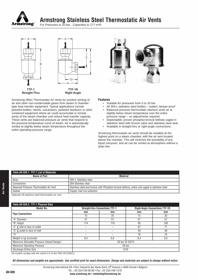
Armstrong Stainless Steel Thermostatic Air VentsFor Pressures to 20 bar…Capacities to 177 m³/h
Armstrong offers Thermostatic Air Vents for positive venting ofair and other non-condensable gases from steam in chambertype heat transfer equipment. Typical applications includejacketed kettles, retorts, vulcanizers, jacketed sterilizers or othercontained equipment where air could accumulate in remoteareas of the steam chamber and reduce heat transfer capacity.These vents are balanced pressure air vents that respond tothe pressure-temperature curve of steam. Air is automaticallyvented at slightly below steam temperature throughout theentire operating pressure range.
Features• Suitable for pressures from 0 to 20 bar• All 304-L stainless steel bodies – sealed, tamper-proof• Balanced pressure thermostatic element vents air at
slightly below steam temperature over the entirepressure range – no adjustments required
• Dependable, proven phosphor-bronze bellows caged instainless steel with bronze valve and stainless steel seat
• Available in straight-thru or right-angle connections
Armstrong thermostatic air vents should be installed at thehighest point on a steam chamber, with the air vent locatedabove the chamber. This will minimize the possibility of anyliquid carryover, and air can be vented at atmosphere without adrain line.
A
B
A
B
C
HD
TTF-1Straight-Thru
TTF-1RRight Angle
Table AV-328-1. TTF-1 List of MaterialsName of Part Material
Body 304–L Stainless steelConnections 304 Stainless steelBalanced Pressure Thermostatic Air Vent Stainless steel and bronze with Phosphor-bronze bellows, entire unit caged in stainless steelGasket Copper clad non-asbestos
Table AV-328-2. TTF-1 Physical DataModel No. Straight-thru Connections TTF-1 Right-Angle Connections TTF-1R
Pipe Connectionsmm mm mm mm15 20 15 20
“A” Diameter 57 57 57 57“B” Height 114 119 95 100“C” C inlet to face of outlet – – 67 71“D” C outlet to face of inlet – – 49 48“H” – – 78 76Weight in kg (screwed) 0,4 0,5 0,4 0,5Maximum Allowable Pressure (Vessel Design) 20 bar @ 232°CMaximum Operating Pressure 20 barDischarge Orifice Size 3/16"
Optional: All stainless steel thermostatic air vent.
LL
All models comply with the article 3.3 of the PED (97/23/EC).
Armstrong International SA • Parc Industriel des Hauts-Sarts (2e Avenue) • 4040 Herstal • BelgiumTel.: +32 (0)4 240 90 90 • Fax: +32 (0)4 248 13 61
www.armstrong.be • [email protected]
Air
Vent
s
All dimensions and weights are approximate. Use certified print for exact dimensions. Design and materials are subject to change without notice.

Armstrong International SA • Parc Industriel des Hauts-Sarts (2e Avenue) • 4040 Herstal • BelgiumTel.: +32 (0)4 240 90 90 • Fax: +32 (0)4 248 13 61
www.armstrong.be • [email protected]
Stainless Steel Thermostatic Air Vent/Vacuum BreakerFor Pressures to 10 bar…Capacities to 93 m³/h
The Armstrong TAVB is a combination thermostatic airvent/vacuum breaker that is ideally suited for steam-filledvessels with modulating controls. The TAVB will vent air andother non-condensables from vessels such as shell and tubeheat exchangers, jacketed kettles and steam coils during theiroperation. It will also break the vacuum that forms during steamcontrol modulation.
This balanced pressure air vent responds to the pressure-temperature curve of steam, and the soft-seated vacuumbreaker responds to 0,0051 bar of vacuum.
Features• Maximum allowable pressure: 20 bar• Maximum allowable temperature: 185°C• Maximum working pressure: 10 bar• All stainless steel welded construction• NPT connections
Armstrong thermostatic air vents should be installed at thehighest point on a steam chamber, with the air vent locatedabove the chamber. This will minimize the possibility of anyliquid carryover, and air can be vented to atmosphere without adrain line.
58 mm
47 mm
87 mm
B
Vacuum Breaker3/8" NPT
Table AV-329-1. TAVB Physical Data (dimensions in mm)Model No. TAVB-2 TAVB-3
Pipe ConnectionsThermostatic Air Vent 15 20Vacuum Breaker 3/8" 3/8"
“A” (Diameter) 57 57“B” (Height) 117 119“C” (C Inlet to Face of Vacuum Breaker) 54 54Weight lb (kg) 0,45 0,57Maximum Allowable Pressure (Vessel Design) 20 bar @ 185°CMaximum Operating Pressure 10 barDischarge Orifice Size 3/16"
L
Table AV-329-2. TAVB List of MaterialsName of Part Material
Body 304L Stainless SteelConnections 304 Stainless SteelBalanced Pressure Thermostatic Air Vent Stainless steel and bronze with phosphor-bronze bellows, entire unit caged in stainless steelGasket Copper clad non-asbestosVacuum Breaker Body 303 Stainless SteelValve Stainless SteelSpring 302 Stainless Steel"O" Ring EPDMScreen Stainless Steel
All dimensions and weights are approximate. Use certified print for exact dimensions. Design and materials are subject to change without notice.
Armstrong International SA • Parc Industriel des Hauts-Sarts (2e Avenue) • 4040 Herstal • BelgiumTel.: +32 (0)4 240 90 90 • Fax: +32 (0)4 248 13 61
www.armstrong.be • [email protected] AV-329
Air Vents
All sizes comply with the article 3.3 of the PED (97/23/EC).

TS-2 Thermostatic Air VentFor Pressures to 3,5 bar…Capacities to 44 m³/h
Armstrong TS thermostatic air vent is offered in both angle andstraight patterns. The TS-2 has a balanced pressurethermostatic element with a high quality multiple-convolutionbellows. It’s ideal for venting air from equipment such as steamradiators and convectors, small heat exchangers, and unitheaters. The TS-2 comes with a strong, cast bronze body and astainless steel seat. The valve and seat are renewable in-line.
MaterialsCap: Bronze, ASTM B62Body: Bronze, ASTM B62Union Nipple: Brass, ASTM B584Valve: BrassValve Seat: Stainless steelElement: Phosphor-bronze bellows
A
C
D
B
A
C
D
B
TS-2 Air Vent Angle Type
TS-2 Air Vent Straight Type
Table AV-330-1. TS-2 Physical DataModel TS-2Pattern Angle Straight
Pipe connectionsmm mm mm mm15 20 15 20
“A” Diameter 41 41 41 41“B” Height 75 76 68 73“C” 65 73 102 114“D” 35 41 28 33Weight in kg (screwed) 0,68 0,79 0,68 0,91
All sizes comply with the article 3.3 of the PED (97/23/EC).
Armstrong International SA • Parc Industriel des Hauts-Sarts (2e Avenue) • 4040 Herstal • BelgiumTel.: +32 (0)4 240 90 90 • Fax: +32 (0)4 248 13 61
www.armstrong.be • [email protected]
Air
Vent
s
All dimensions and weights are approximate. Use certified print for exact dimensions. Design and materials are subject to change without notice.

TV-2 Thermostatic Air VentFor Pressures to 9 bar…Capacities to 78 m³/h
Armstrong offers the Model TV-2 Balanced PressureThermostatic Air Vent for positive venting of air from chambertype heat transfer equipment with no loss of steam. Typicalapplications include jacketed kettles, retorts, vulcanizers,jacketed sterilizers or other contained equipment where aircould accumulate at the top of the steam chamber and reduceheat transfer capacity.
The Model TV-2 is a balanced-pressure thermostatic air ventthat responds to the pressure-temperature curve of steam atany pressure from light vacuum to maximum operatingpressure. Air is automatically vented at slightly below steamtemperature throughout the entire operating pressure range.
The thermostatic element is a charged multi-convolutionphosphor bronze bellows caged in stainless steel. Valve andseat are also stainless steel designed to meet the most rigidcycling specifications known for this type of service.
Features• Stainless steel hemispherical valve and seat• Thermostatic element comprises a multi-convolution
phosphor bronze bellows caged in stainless steel• Thermostatic element is charged with water to provide
positive opening of the valve at slightly below steamtemperature and positive closing in the presence ofsteam throughout the operating pressure range
• ASTM B62 cast bronze body
Armstrong Model TV-2 Thermostatic Air Vents should beinstalled at the highest points of steam chambers with inletconnections to the vents higher than the highest points of thechambers. Thus installed there is a minimum hazard of anyliquid carryover and air can be vented to atmosphere with nodrain line necessary.
All dimensions and weights are approximate. Use certified print for exact dimensions. Design and materials are subject to change without notice.
TV-2 Thermostatic Air Vent
Table AV-331-1. TV-2 Physical Data
Pipe Connectionsmm15
“A” (Diameter) 56“B” (Height) 89Weight in kg (screwed) 0,8Maximum Operating Pressure 9 barMaximum Temperature 177°C
Table AV-331-2. TV-2 MaterialsName of Part Material
Body & Cap Cast bronze ASTM B62Gasket Compressed non-asbestos
Thermostatic UnitBellowsCage and Cover
Phosphor bronzeStainless steel
Thermostatic Unit Gasket Copper cladAll sizes comply with the article 3.3 of the PED (97/23/EC).
Armstrong International SA • Parc Industriel des Hauts-Sarts (2e Avenue) • 4040 Herstal • BelgiumTel.: +32 (0)4 240 90 90 • Fax: +32 (0)4 248 13 61
www.armstrong.be • [email protected] AV-331
Air Vents

1-AVCW See-Thru Air Vent for Ozone ApplicationsFor Pressures to 10 bar or Specific Gravity Down to 0,80
What Is Ozone?Ozone is a gas that forms naturally during thunderstorms whenlightning converts normal oxygen molecules (O2) into ozone(O3). The fresh, sweet smell in the air after a storm is the smellof ozone. The unstable ozone molecule reacts rapidly with mostsubstances and is an extremely strong natural oxidant.
How Is Commercial Ozone Produced?Ozone can be formed by exposing air to ultraviolet light;however, the most common method of generating ozone is bypassing air through an electrical discharge. Because ozone hasstrong oxidizing properties, its production requires corrosion-resistant equipment.
How Is Ozone Used in Water Filtration and Purification?Because ozone is such an effective oxidant, it kills viruses,bacteria, mold, mildew, fungus and germs. Passing ozonethrough water achieves high purification rates without anychemical residue. Oxygen is the only by-product.
Typical Customer Applications:• Purifying standing ground water in Third World countries.• Conditioning water for poultry and livestock.• Purifying water in the bottled water industry.• Filtering and purifying water for process applications.
A See-Thru Body Shows You It’s WorkingNow, you can literally see what you’ve been missing. TheArmstrong 1-AVCW See-Thru Air Vent lets you easily check itsoperating condition. You won’t have to waste time and moneyscheduling maintenance that isn’t needed, and you can quicklyreact to a condition before it becomes a problem.
Efficient OperationSimple ball-float mechanism doesn’t need electricity to operate.The air vent automatically discharges only when air or gas ispresent. No liquid is lost, as with manual venting.
Positive SeatingFree-floating valve mechanism ensures positive seating andprevents liquid loss. There are no fixed pivots to wear or createfriction. Wear points are heavily reinforced for long life.
Corrosion ResistanceLong-lasting PBT (polybutylene terephthalate) cap providestrouble-free operation. Stainless steel internal parts resistcorrosion and reduce maintenance.
Compare – and Save the DifferenceSeeing really is believing – especially when you compare theArmstrong 1-AVCW See-Thru Air Vent with manual venting.Measure the time and money you can save with a moreefficient, easier-to-maintain system. For more information ortechnical assistance, contact your local ArmstrongRepresentative.
Note: The Armstrong 1-AVCW should not be used in anenvironment where there are high levels of ketones orchlorinated or aromatic hydrocarbons.
1-AVCW
Inlet
AlternateInlet
Outlet
Table AV-332-1. 1-AVCW List of MaterialsName of Part Material
Cap PBT (Polybutylene Terephthalate)Body Polysulfone*O-Rings (Body Cap and Fitting) VitonFloat Lever and Screws Stainless SteelValve & Seat Stainless SteelFitting PBT (Polybutylene Terephthalate)Retainer Ring Zinc Plated Steel
Table AV-332-2. 1-AVCW Physical Datamm
Inlet Connection (In Body) 20Inlet Connection (Alternate) 15Outlet Connection 15“A” Face-to-Face 89“B” Height 172“C” Bottom to C 152Maximum Allowable Pressure (Vessel Design) 10 bar @ 66°CMaximum Operating Pressure 10 barSpecific Gravity Range 1,00 to 0,80Weight in kg (screwed) 0,5
Table AV-332-3. 1-AVCW CapacityDifferential Pressure
Orifice Size m³/hbar1,0
1/8"
7,32,0 11,03,5 16,15,0 22,27,0 28,78,5 34,810,5 41,1
* UV sensitive
Note: Discharge of air through an orifice in m³/h at a standard atmosphericpressure of 1 bar(a) and 21°C.
L
All sizes comply with the article 3.3 of the PED (97/23/EC).
Armstrong International SA • Parc Industriel des Hauts-Sarts (2e Avenue) • 4040 Herstal • BelgiumTel.: +32 (0)4 240 90 90 • Fax: +32 (0)4 248 13 61
www.armstrong.be • [email protected]
Air
Vent
s
All dimensions and weights are approximate. Use certified print for exact dimensions. Design and materials are subject to change without notice.
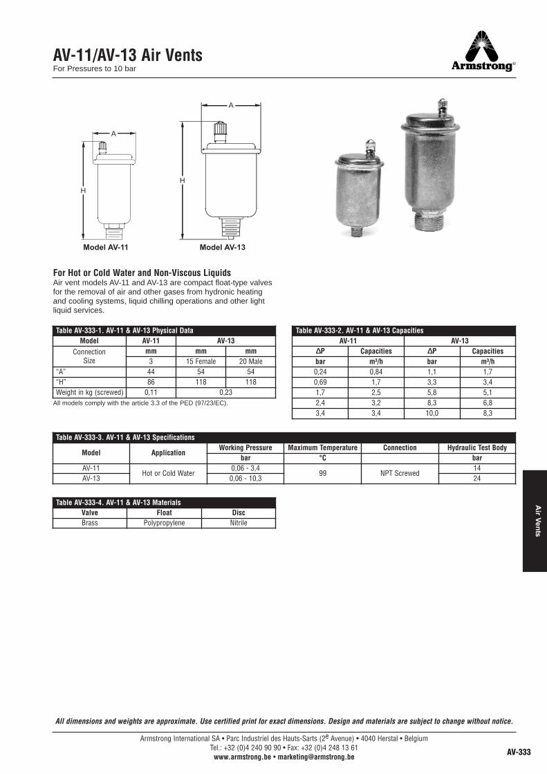
AV-11/AV-13 Air VentsFor Pressures to 10 bar
All dimensions and weights are approximate. Use certified print for exact dimensions. Design and materials are subject to change without notice.
For Hot or Cold Water and Non-Viscous LiquidsAir vent models AV-11 and AV-13 are compact float-type valvesfor the removal of air and other gases from hydronic heatingand cooling systems, liquid chilling operations and other lightliquid services.
A
H
A
H
Model AV-11 Model AV-13
Table AV-333-1. AV-11 & AV-13 Physical DataModel AV-11 AV-13
ConnectionSize
mm mm mm3 15 Female 20 Male
“A” 44 54 54“H” 86 118 118Weight in kg (screwed) 0,11 0,23
Table AV-333-2. AV-11 & AV-13 CapacitiesAV-11 AV-13
∆∆P Capacities ∆∆P Capacitiesbar m³/h bar m³/h0,24 0,84 1,1 1,70,69 1,7 3,3 3,41,7 2,5 5,8 5,12,4 3,2 8,3 6,83,4 3,4 10,0 8,3
Table AV-333-3. AV-11 & AV-13 Specifications
Model ApplicationWorking Pressure Maximum Temperature Connection Hydraulic Test Body
bar °C barAV-11
Hot or Cold Water0,06 - 3,4
99 NPT Screwed14
AV-13 0,06 - 10,3 24
Table AV-333-4. AV-11 & AV-13 MaterialsValve Float DiscBrass Polypropylene Nitrile
All models comply with the article 3.3 of the PED (97/23/EC).
Armstrong International SA • Parc Industriel des Hauts-Sarts (2e Avenue) • 4040 Herstal • BelgiumTel.: +32 (0)4 240 90 90 • Fax: +32 (0)4 248 13 61
www.armstrong.be • [email protected] AV-333
Air Vents