Air Traffic Controller - Welcome to MilitaryNewbie.com ... · NONRESIDENT TRAINING COURSE Air...
594
NONRESIDENT TRAINING COURSE Air Traffic Controller NAVEDTRA 14342 DISTRIBUTION STATEMENT A: Approved for public release; distribution is unlimited.
Transcript of Air Traffic Controller - Welcome to MilitaryNewbie.com ... · NONRESIDENT TRAINING COURSE Air...

NONRESIDENTTRAININGCOURSE
Air Traffic Controller
NAVEDTRA 14342
DISTRIBUTION STATEMENT A: Approved for public release; distribution is unlimited.
PREFACE
About this course:
This is a self-study course. By studying this course, you can improve your professional/military knowledge, as well as prepare for the Navywide advancement-in-rate examination. It contains subject matter about day-to-day occupational knowledge and skill requirements and includes text, tables, and illustrations to help you understand the information. An additional important feature of this course is its reference to useful information in other publications. The well-prepared Sailor will take the time to look up the additional information.
History of the course:
• Sep 1998: Original edition released. • Aug 2003: Administrative update released. Technical content was not reviewed or revised.
Published by NAVAL EDUCATION AND TRAINING
PROFESSIONAL DEVELOPMENT AND TECHNOLOGY CENTER
NAVSUP Logistics Tracking Number0504-LP-102-2477


TABLE OF CONTENTS
CHAPTER PAGE
1. Aviation Weather ................................................................................................... 1-1
2. Air Navigation and Aids to Air Navigation ........................................................... 2-1
3. Military Aircraft Identification, Performance, and Characteristics........................ 3-1
4. Airport Lighting, Markings, and Equipment.......................................................... 4-1
5. Air Traffic Control Equipment............................................................................... 5-1
6. Airspace Classification........................................................................................... 6-1
7. Flight Assistance Service ....................................................................................... 7-1
8. General Flight Rules and IFR/SVFR Control Procedures...................................... 8-1
9. Control Tower Operations...................................................................................... 9-1
10. Radar Operations……………………………………………………………… 10-1
11. Shipboard Operations…………………………………………………………. 11-1
12. Facility Operations……………………………………………………………. 12-1
INDEX.........................................................................................................................................INDEX-1


CHAPTER 1
AVIATION WEATHEROverview
Introduction
Objectives
Weather phenomenon, as it affects aviation, is an integral part of your job as anAir Traffic Controller (AC). You will be part of a team to keep pilots informedof current, and forecasted weather conditions that will effect the safety of flightand sometimes the pilots' very survival.
As an AC, you must accurately report weather conditions and recognize anydifferences between the actual weather conditions, as observed from the tower,and those indicated by the current report. You must understand how currentand developing meteorological conditions affect just about every decision youand the pilot make, from the preflight planning stage to landing rollout. It iscritical that you understand the information in this chapter and realize theimpact weather has on the safe, expeditious flow of air traffic.
The material in this chapter will enable you to:
Identify standard (sea level) pressure and associated atmosphericterms, their characteristics, and effects.Identify the major cloud formations and types, their generalcharacteristics, and the levels at which they occur.Identify the types, effects, designations, and characteristics offronts.State possible controller operational considerations for certainweather conditions.Identify the activities that provide weather service to pilots, and themethods used to distribute weather information.Decode weather data using standard codes and contractions.State the proper broadcasting procedures and phraseology used totransmit weather information to pilots.Obtain weather information from pilots and relay it to aircraft andarea air traffic control facilities.Identify and explain the different types of forecasts, advisories, andwarnings issued by the Navy and the National Weather Service(NWS).
Continued on next page
1-1

Overview, Continued
Acronyms The following table contains a list of acronyms that you must know tounderstand the material in this chapter:
Acronym Meaning
AC Air Traffic Controller
AG Aerographer's Mate
AGL Above ground level
AIRMET (WA) Airmen's meteorological information
ASOS Automated surface observation system
AWOS Automated weather observation system
FAA Federal Aviation Administration
FIDO Flight data input/output
METAR Aviation Routine Weather Reports
MSL Mean sea level
nm Nautical mile
NWS National weather service
PIREP Pilot weather report
RCR Runway condition reading
RSC Runway surface condition
SIGMET (WS) Significant meteorological information
SPECI Aviation Selected Special Weather Reports
TAF Terminal area forecast
UTC Coordinated Universal Time
WST Convective SIGMET
Continued on next page
1-2

Overview, Continued
Topics This chapter is divided into six sections:
1-B-1
Section Topic See Page
A Atmosphere 1-A-1
B Clouds and Their Characteristics
C Fronts and Associated Weather 1-C-1
D Weather Hazards 1-D-1
E Weather Observation Codes and Phraseology 1-E-1
F Weather Forecasts, Advisories, and Warnings 1-F-1
1-3


Section AAtmosphere
Overview
Introduction All of the weather that we experience occurs in the atmosphere, which is a thinblanket of gases that surrounds the earth. The radiant energy of the sun is thecatalyst that causes the different weather and wind patterns that we experience.In this section we will discuss some of the basic characteristics of ouratmosphere.
In this section This section covers the following topics:
Topic See Page
Earth's Atmosphere 1-A-2
Atmospheric Pressure and Temperature 1-A-4
Pressure Systems 1-A-7
1-A-1

Earth's Atmosphere
Background The atmosphere is a thin blanket of gases, mostly nitrogen and oxygen, thatsurrounds the earth and is held in place by the earth's gravity. All of theweather that we experience occurs within 7 miles of the earth's surface. Theradiant energy of the sun causes the different weather and wind patterns that weexperience. In this section, we will discuss some of the basic characteristics ofour atmosphere.
Layers of theatmosphere
The earth's atmosphere extends upward many hundreds of miles and is dividedinto five basic layers with narrow boundaries between the bottom four layers.
Layer orBoundary
Remarks
Troposphere Extends upwards from the earth’s surface approximately 7miles. All weather occurs in this layer.
Tropopause Boundary separating the troposphere and the stratosphere.Height varies, normally found at higher elevations nearequatorial regions and decreases in height towards theNorth and South Pole. Jet stream occurs in the tropopause.
Stratosphere Extends upwards to approximately 30 miles. Temperatureincreases with height. Ozone concentration is heaviest inthis layer.
Additional boundaries and layers above the stratosphere include thestratopause, mesophere, thermosphere, and ectosphere.
Continued on next page
1-A-2

Earth's Atmosphere, Continued
Diagram A vertical cross section of the earth's atmosphere is depicted below.
1-A-3

Atmospheric Pressure and Temperature
Background The atmosphere is made up of molecules that we call air. These air moleculeshave weight (approximately 1.2 ounces per cubic foot at sea level), and theamount of weight these air molecules exert on the earth's surface is calledatmospheric pressure. You must understand how an aircraft uses atmosphericpressure to determine altitude and how pressure and temperature changes havean affect on the aircraft's instruments.
Units of There are two basic units used to measure and report the atmospheric pressure,measurement inches and millibars.
Atmospheric pressure is measured using either a mercury or aneroid barometer.Air pressure pressing against a mercury barometer causes mercury to rise in anevacuated glass tube. Air pressure at sea level causes the mercury to rise in theglass tube, on the average, 29.92 inches (standard sea-level pressure). Mercuryis used because it is such a dense, heavy liquid, the same pressure would causewater to rise approximately 400 inches in the same tube. An aneroid barometeruses a thin metal strip in an evacuated case to measure pressure.
In the United States, we report the barometric pressure in inches (for example,29.92 inches) and this is the unit of measurement that you will be mostconcerned with. However, a pilot will occasionally ask for the altimeter inmillibars which is the scientific unit of measurement. Normally you will haveto contact the weather reporting service for your station to obtain this reading.The table below gives a comparison of inches to millibars:
Inches
27.17
27.46
29.92
28.05
28.64
26.58 900
26.87 910
27.76 940
28.35 960
Millibars Inches Millibars
28.94 980
29.24 990
920 29.53 1000
930 29.82 1010
1013.25
950 30.12 1020
30.42 1030
970 30.71 1040
Continued on next page
1-A-4

Atmospheric Pressure and Temperature, Continued
Altimeters Atmospheric pressure is used to indicate the altitude of an aircraft. Abarometer (aneroid type) carried on board an aircraft is called an altimeter.The altimeter has a scale to indicate altitude instead of pressure. As an aircraftincreases altitude there is less air above the aircraft therefore less pressure onthe altimeter. An aircraft uses surface pressure as a reference point, so the pilotmust change altimeter setting as he flies along a route of flight below 18,000feet (above 18,000 feet all aircraft set their altimeters at 29.92). It is critical toflying safety that an aircraft have the correct altimeter setting for the area it isoperating in.
Effects of An aircraft must have the correct altimeter setting for the area in which it ischanges in operating since this is what altitude and vertical separation are based on.atmospheric Without having the correct altimeter setting the indicated altitude of the aircraftpressure will not be correct.
For example, when an aircraft flies from a high-pressure area into a low-pressure area and the altimeter setting is not corrected, the altimeter will readtoo high. Going from a low-pressure area to a high-pressure area, the altimeterwill read too low. A simple rule to help you remember this is:
Flying From Altimeter Reads
High to low pressure
Low to high pressure
Too high
Too low
Effects ofchanges intemperature
The same rule applies to temperature changes. The altimeter of a plane flyingfrom a low-temperature area into a high temperature area will read too low; andfrom a higher temperature area to a lower temperature area, too high.
Temperature Altimeter Reads
High to low temperature Too high
Low to high temperature Too low
Continued on next page
1-A-5

Atmospheric Pressure and Temperature, Continued
Errors inaltimeter
The approximate amount of error in the altimeter reading that is due toincorrect altimeter setting can be determined for the lower levels of theatmosphere by applying the corrections in the following table:
Pressure Change Altimeter Error
1 inch of mercury 1,000 feet
1/10 inch of mercury 100 feet
1/100 inch of mercury 10 feet
1-A-6

Pressure Systems
Introduction Pressure systems are either high-pressure (anticyclonic) areas or low-pressure(cyclonic) areas. A basic understanding of pressure systems, theirdistinguishing characteristics, and the weather phenomena associated with themis necessary to understand concepts that will be presented later in this chapter.
Formation andmovement
One of the reasons that high and low-pressure areas form is the uneven heatingof the earth’s surface. Areas near the equator receive more heat which causesthe air to expand and rise which produces an area of low pressure.
The atmosphere tends to maintain equal pressure over the entire earth. Whenthis equilibrium is upset (for example, by the formation of a high- pressurearea), air flows from areas of high pressure to areas of low pressure attemptingto maintain equal pressure. The heavier denser air from the north and southpoles moves along the earth’s surface towards the equator while the lighterwarmer air moves towards the poles.
As this air moves, it doesn’t travel in a straight line from equator to pole,because it is affected by:
The earth's rotationUneven heating over water and landSeasonal and daily temperature changes
The earth's rotation causes the air to flow to the right of its normal path in thenorthern hemisphere and to the left in the southern hemisphere. This explainswhy, in the northern hemisphere, weather patterns and high- and low-pressuresystems generally move from west to east.
Cyclones (low-pressuresystems)
In a low-pressure system, barometric pressure decreases toward the center. Thewind flow around the system is counterclockwise in the northern hemisphere.A low-pressure system is generally associated with unfavorable flyingconditions because of low clouds, restricted visibility, and strong gusty winds.Hurricanes, Typhoons, and Tropical Storms are examples of severe low-pressure systems.
Continued on next page
1-A-7

Pressure Systems, Continued
Anticyclones(high-pressure
In the northern hemisphere, the wind flow around a high-pressure area is
systems)clockwise. Flying conditions are generally more favorable in high-pressuresystems because there are fewer clouds, better visibility, less wind, and fewerareas of concentrated turbulence. The diagrams below depict wind flowaround low- and high-pressure areas.
1-A-8
Section BClouds and Their Characteristics
Overview
Introduction Clouds have been called signposts in the sky. They are an indication of whatthe atmosphere is doing. Understanding cloud types will help you to predictweather conditions, recognize potential weather hazards, and assist the pilot inthe safe handling of his or her flight.
In this section This section covers the following topics:
Topic See Page
Cloud Composition and Formations 1-B-2
Cloud Types and Characteristics 1B-3
1-B-1

Clouds Composition and Formations
Introduction Clouds are composed of small liquid water droplets and/or ice crystals.
Cloudcomposition
Clouds form when the temperature of the surrounding air is between 5°F and32°F and are composed mostly of supercooled water droplets with smallamounts of ice crystals. Below 5°F, clouds are composed almost entirely ofice crystals.
Cloud particles (droplets) are extremely small, about one-thousandth of an inchin diameter, and as they become more dense, or clustered together, theybecome visible as clouds. The average raindrop contains about one milliontimes the water in a cloud droplet.
Cloudformations
Clouds are arranged in three families, low (surface to 6500 feet), middle (6500feet to 16,500 feet) and high (16,500 feet to 45,000 feet) and are categorizedinto 10 basic types that have many different forms and varieties. Twoadditional types of cloud formations are cumulonimbus mamma and lenticular.
1-B-2

Cloud Types and Characteristics
Introduction There are many different types of clouds with their own distinguishingcharacteristics.
Cloud types The table below lists some of the more common types of clouds, theircharacteristics, and some of the hazards associated with each.
Type
Cirrus
Characteristics Hazards to Aviation
Fibrous and delicate in appearance. Flying conditions are good.Clouds look like white wisps against the Negligible turbulence. Pure icesky. First sign of approaching bad crystal composition of theseweather. When these clouds become clouds precludes surface icingmore compact and merge into on the aircraft.cirrostratus, an approaching warm frontmay be indicated.
Cirrocumulus Appear like fleecy flakes or small white Light to moderate turbulence.cotton balls. Like the scales on a No icing on aircraft surfaces.fish—often called a mackerel sky.
Cirrostratus Smooth, thin-layered cloud covering all Icing and turbulence usuallyor most of the sky, giving the sky a milky present; no hazard to flying.appearance. Produces halo around sun ormoon. When these clouds lower,thicken, and merge into altostratus, theapproach of a warm front and badweather is imminent.
Altocumulus Sometimes appear like cirrocumulus, but Poor visibility within thesethe balls or flakes are thicker and grayer. clouds. Light to moderateAppear similar to a herd of sheep in the turbulence and icing. The icingsky. The underside of each cloud is dark is usually the clear type.because of the thickness.
Altostratus Appear as a thick gray or blue-graysmooth overcast. Thicker and lesstransparent than cirrostratus clouds.Precipitation in the form of light rain orsnow.
Light to moderate icing(predominantly rime ice). Lightturbulence. Visibility withinthese clouds is 50 to 200 yards.
Continued on next page
1-B-3

Clouds Types and Characteristics, Continued
Type
Nimbostratus
Characteristics
Thick, dark gray clouds that areformless in appearance.Precipitation is always falling fromthese clouds (may not always reachthe surface).
Hazards to Aviation
Moderate to heavy turbulenceand icing with very poorvisibility within and below thecloud.
Stratocumulus Occur as an extensive and fairly Poor visibility within theselevel layer marked by thick rolls and clouds. Light to moderatedark, rounded masses underneath. turbulence. Moderate icingPrecipitation infrequent; when conditions. May form clear oroccurs, it is in the form of very light rime ice.rain showers or snow flurries.
Stratus Flat, shapeless, dull gray, uniformlayer of cloud. Precipitation in theform of drizzle only.
Only light turbulence andmoderate icing may be present.Visibility is very poor whendrizzle occurring.
Cumulus Dense clouds with verticaldevelopment. The cloud’s uppersurfaces are dome shaped andexhibit rounded protuberances,while their bases are nearlyhorizonal.
Strong updrafts occur within andunder these clouds. Turbulenceand icing of varying intensitiesare common depending on theextent of vertical development.
Cumulonimbus
CumulonimbusMamma
Lenticular
Cumulus clouds with great vertical Extreme turbulence and severedevelopment that resembles icing. Severe up and downmountains or towers. Tops may drafts.. Microbursts and low-extend higher than 60,000 feet and level wind shear occur under thisresemble an anvil. Precipitation is type of cloud. Damaging hail isviolent, intermittent showers. possible.
Large, baggish clouds with This type of cloud indicatesprotuberances, like udders or extreme turbulence. Conditionspouches, on the undersurface. ideal for tornado development.
Clouds have the shape of lenses or Usually associated with extremealmonds. Normally formed by wind turbulence.flow in mountainous areas.
Continued on next page
1-B-4

Clouds Types and Characteristics, Continued
1-B-5


Section CFronts and Associated Weather
Overview
Introduction In this section, we will discuss the general nature of fronts, how fronts formand move, and the weather patterns associated with the four classificationsof fronts (cold, warm, stationary, and occluded).
In this section This section covers the following topics:
Front Classification
Cold Fronts
Warm Fronts
Stationary Fronts
Occluded Fronts
Topic See Page
1-C-2
1-C-4
1-C-5
1-C-6
1-C-7
1-C-1

Front Classification
Background To understand fronts, we must first define and understand what an air mass is.
An air mass is any huge body of air whose physical properties (temperatureand moisture) are horizontally and vertically uniform. When air stagnates overcertain regions, it acquires properties from the underlying surface (sourceregion) and forms an air mass. The prevailing weather over any area at anygiven time generally depends on the properties and characteristics of theprevailing air mass. In time, these air masses move out of their source region,because of the general circulation of the earth's atmosphere, the terrain, andother factors. In the northern hemisphere, cold air masses from the polarregions tend to move southward, while warm air masses from the tropicalregions tend to move northward.
When two different air masses meet, the boundary or surface that separatesthese air masses is called a front.
Classification Fronts are generally classified according to the relative motions of the airmasses involved. The four chief classifications and their descriptions arecontained in the following table:
Type
Cold front
Description
A front whose motion is such that cold air displaceswarm air at the surface.
Warm front A front whose motion is such that warm air replaces coldair at the surface.
Stationary A front that has little or no motion.front
Occluded front A complex front resulting when a surface cold frontovertakes a warm front.
Continued on next page
1-C-2

Front Classification, Continued
Classification(continued)
The weather associated with fronts and frontal movement is called frontalweather. It is more complex and variable than air mass weather. The typeand intensity of frontal weather is determined by a number of things (i.e.slope of the front, water vapor content, stability of the air mass . . . ) and mayrange from a minor wind shift with no clouds or other visible weatheractivity to severe thunderstorms accompanied by low clouds, poor visibility,hail, and severe turbulence and icing. Let's consider each of the frontalcategories and the weather pattern each usually produces.
1-C-3

Cold Fronts
Introduction A cold front occurs when cold air invades a region occupied by warm air.
Cold frontcharacteristics
In a cold front, the cold air wedges under the warm air pushing the warm airupwards.
Certain weather characteristics and conditions are associated with thepassage of cold fronts. In general, the temperature and humidity decrease,pressure rises, and in the northern hemisphere the wind shifts clockwise(clockwise movement on the wind direction indicator–usually fromsouthwest to northwest) with the passage of a cold front.
When the warm air mass is unstable and moist, showers and thunderstormsoccur just ahead of the front, and rapid clearing occurs behind the front.Squall lines and tornadoes are associated with fast moving cold fronts.
When the warm air is relatively dry, a cold front may not produce precipitationor clouds.
1-C-4

Warm Fronts
Introduction A warm front occurs when cold air retreats before an advancing mass of warmair.
Warm front With a warm front, the warm air slides over the cold air.characteristics
As with a cold front, the weather associated with a warm front variesdepending on the degree of stability and moisture of the warm air mass.
Certain characteristics and weather conditions are associated with the passageof warm fronts. In the northern hemisphere, the winds veer from southeast tosouthwest or west, but the shift is not as pronounced as with the cold front.Temperatures are colder ahead of the warm front and warmer after the frontpasses. Clearing usually occurs after the passage of a warm front, but undersome conditions drizzle and fog may occur within the warm sector. Normally,the speed of a warm front is less than that of cold fronts; the average speed of awarm front is about 10 knots.
1-C-5

Stationary Fronts
Introduction Sometimes the opposing forces of different air masses are such that the frontalsurface shows little or no movement. Since neither air mass is replacing theother, the front is known as a stationary front.
Stationary The weather conditions occurring with a stationary front are similar to thosefront found with a warm front but are usually less intense. An annoying feature ofcharacteristics the stationary front and its weather pattern is that it may persist and hamper
flights for several days in the same area.
1-C-6
Occluded Front
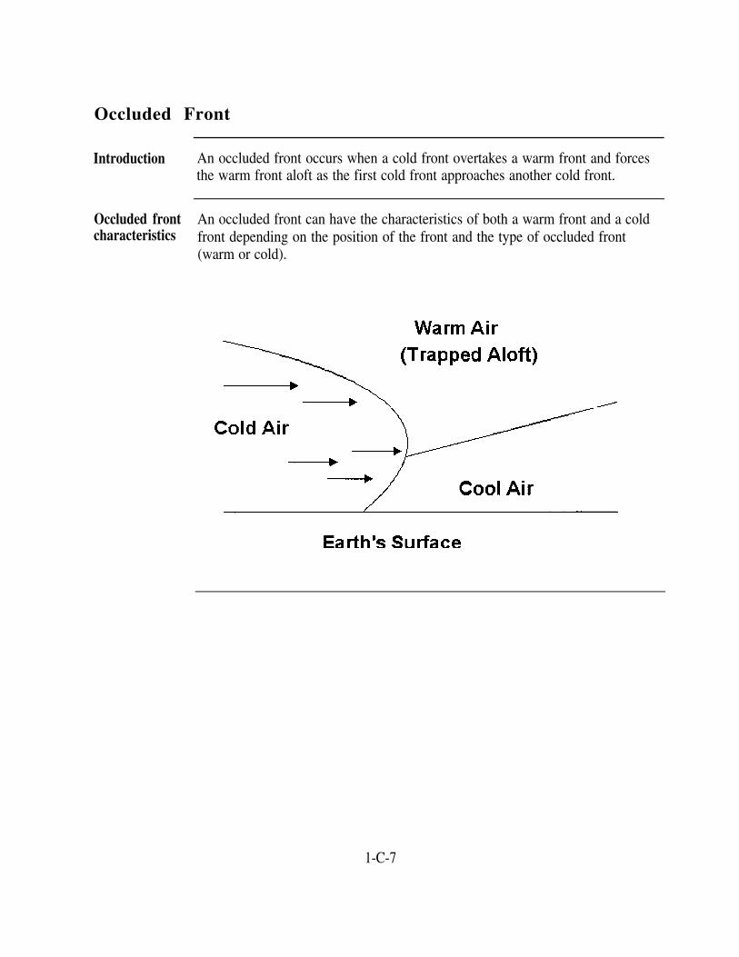
Introduction An occluded front occurs when a cold front overtakes a warm front and forcesthe warm front aloft as the first cold front approaches another cold front.
Occluded front An occluded front can have the characteristics of both a warm front and a coldcharacteristics front depending on the position of the front and the type of occluded front
(warm or cold).
1-C-7


Section DWeather Hazards
Overview
Introduction In this section, we will discuss some of the more serious weather hazards. Acomprehensive knowledge of these hazards and how they affect an aircraft isessential to providing good service. This knowledge also enables you to planahead and keep pilots informed of known and anticipated weather conditions.
In this section This section covers the following topics:
Fog and Precipitation
Icing
Turbulence
Thunderstorms
Topic See Page
1-D-2
1-D-5
1-D-9
1-D-11
1-D-1

Fog and Precipitation
Introduction Fog is defined as a cloud on the earth's surface. It has sufficient density in theatmosphere to interfere with visibility.
Fog consists of visible water droplets or ice particles suspended in theatmosphere. It differs from other clouds in that it exists on the ground or overthe surface of bodies of water. It differs from rain or mist in that its water orice particles are more minute and are suspended (they do not fall earthward).
Fog formation The difference between the dew point (the temperature to which air, at constantpressure, and water vapor content must be cooled for saturation to occur) andthe temperature is used to predict fog formation. The smaller the differencebetween the temperature and the dew point, the greater the possibility of fogformation. Dew point spread is the term used to describe the difference, indegrees, between the two. Fog seldom forms when the dew point spread isgreater than 4° F.
Wind is another factor that influences the formation of fog. The followingtable shows the various wind conditions and whether or not they are favorablefor the formation of fog:
Wind Fog Formation PotentialCalm Fog will form but is generally very shallow.
Light With dust-laden air, is ideal for fog formation.Produces deep layers of fog.
Moderately strong Tends to keep fog from forming as it circulates theair too rapidly for fog producing conditions to exist.
Strong Will dissipate fog that has already formed.
Continued on next page
1-D-2

Fog and Precipitation, Continued
Air mass fog Fog is divided into two classes: air mass fog and frontal fog. We willdiscuss each class separately since there are different requirements thatgovern the formation of each.
Air mass fog occurs within a given air mass and is formed when the layer ofair close to the earth's surface is cooled by contact with a colder surfacebelow.
radiation fog, advection fog, upslope fog, and steam fog.
There are four types of air mass fog. Each type gets its name from theparticular manner in which air is cooled to the dew point. The four types are
TypeRadiation fog
Advection fog
Upslope fog
Steam fog
DescriptionMore commonly known as ground fog, it is themost common problem for air traffic control.Usually forms at night and dissipates before midmorning. Best conditions for formation are a coolclear night, light wind, and high humidity.
Because advection fog covers large areas, it isconsidered the most dangerous to aviation. Formswhen air moves over a land or water surface that iscolder than the air mass that is passing over it.
Forms when air is forced to ascend a gradual slope.Forms in very deep layers and requires considerabletime to dissipate.
Forms when cold air moves over warm water.Evaporation from the surface of the warm watersaturates the cold air and causes fog to form.
Continued on next page
1-D-3

Fog and Precipitation, Continued
Frontal Fog Frontal fog is another hazard that must be added to the list of weathertroubles associated with fronts. There are two classes of frontal fog: warm-front fog and cold-front fog.
Class
Warm-front fog
Description
Much more extensive than cold-front fog and is adefinite hazard to flight operations. Formed by rainfalling from warm air into cold air along the frontalsurface.
Cold-front fog Cold-front fog is rare. It forms in the cold air massjust behind the cold front. This type of fog dissipatesrapidly due to the fast movement of cold fronts.
Precipitation Precipitation includes all forms of moisture that fall to the earth’s surface.Snow, drizzle, and rain are the most common forms of precipitation thatcause a restriction to visibility.
TypeSnow
CharacteristicsUsually the most effective in reducing visibility. Heavysnow and blowing snow frequently reduce surfacevisibility to near zero.
Rain
Drizzle
Rarely reduces surface visibility to below 1 mile. Has atendency to wash dust, smoke, and fog out of the air.
Often accompanied by fog and results in lower visibilitythan rain.
1-D-4

Icing
Background A severe weather hazard to flying is airframe icing. Having a throughunderstanding of when and how ice forms on aircraft will enable you to lendinvaluable assistance to pilots.
The formation of ice on an aircraft reduces lift and thrust by adding weight tothe structure and changing the airfoil shape of wings, tail, and propeller(s).There are three types of airframe ice: rime, clear (glaze), and frost. Icingconditions encountered in flight are a combination of rime and clear ice, withthe characteristics of one or the other being dominant. Frost usually forms onaircraft on the ground. For the formation of ice on aircraft in flight, twoconditions are necessary: the aircraft must be flying through rain, drizzle, orcloud droplets; and at the time the water droplets strike the aircraft, theirtemperature and the temperature of the surface of the aircraft must be 32° F orcolder. Heaviest airframe icing generally occurs within the temperature rangeof 15°F to 32°F provided moisture is available.
Clear ice Clear ice, sometimes referred to as glaze ice, is considered the most serious ofthe three types. It is clear, dense, solid, and adheres firmly to the structure uponwhich it forms. If the water droplets strike an aircraft in such rapid successionthat none has a chance to freeze before the next strikes in the same place, theleading edges of the aircraft structures are kept covered by a film of liquidwater. This film of water, cooled by contact with the colder air and by partialevaporation, freezes from the inside out, forming a clear, dense, strong layer ofice attached to the wing or other surfaces upon which it is freezing. Clear iceon an airfoil is depicted below.
Continued on next page
1-D-5

Icing, Continued
Clear ice Some of the conditions that produce a liquid film of water on aircraft(continued) favorable to the formation of clear ice are:
Large water droplets such as are found in cumuliform cloudsLarge number of cloud droplets (dense clouds)Temperature just slightly below freezingAn unstable or conditionally unstable air mass
Clear icing does not seriously distort airfoil shape but can add appreciably tothe aircraft's weight.
Rime ice Rime ice is a rough, whitish, opaque deposit of ice formed from tiny super-cooled water drops found in the stratiform clouds of stable air. Rime iceusually occurs at a lower temperature than does clear ice.
Unlike clear ice, rime forms as each super-cooled water droplet that strikesthe airfoil freezes completely before another strikes in the same place. Theresulting deposit is tiny pellets of ice frozen together in a spongy mass.Rime ice on an airfoil is depicted below.
Continued on next page
1-D-6

Icing, Continued
Rime ice(continued)
The conditions that favor the formation of rime ice are:
Temperatures far below freezing
Very small water droplets such as are found in stratiform cloudsA relatively small number of water droplets that are found inclouds that are not dense
Rime ice weighs less than clear ice, but rime ice may seriously distort airfoilshape and thereby diminish lift.
Frost Frost is a light, whitish, feathery crystalline ice, snow-like in character. Itforms a dangerous coating on an aircraft surface that adds drag and alters theaerodynamic characteristics of the aircraft. Frost occurs when thetemperature on the surface of the aircraft is below freezing at the timecondensation takes place. This icing condition usually forms on aircraft onthe ground. It can also form on airborne aircraft if the aircraft very quicklyflies from a region where the temperature is well below freezing to a regionwhere the temperature is considerably higher and the air is very moist.
Carburetoricing
In addition to the three types of airframe icing, another type of icing thatmerits discussion is carburetor icing. Carburetor icing occurs over a widerange of temperatures and gives the effect of slowly closing the throttle.Carburetor ice forms when the vaporization of fuel is combined with theexpansion of air as it passes through the carburetor, and it can cause acomplete engine failure.
Continued on next page
1-D-7

Icing, Continued
Icing intensities Aircraft icing is classified into four intensities for reporting purposes. Thefollowing table contains the four intensity categories and a brief descriptionof each:
IntensityTrace
Light
Moderate
Severe
DescriptionIce has become perceptible. Unless encountered for anextended period of time (over 1 hour), it is not hazardouseven though deicing/anti-icing equipment is not used.The rate of accumulation may create a problem if flight isprolonged in this environment (over 1 hour). Occasionaluse of deicing/anti-icing equipment removes/preventsaccumulation. It does not present a problem if thedeicing/anti-icing equipment is used.
The rate of accumulation is such that even short encountersbecome potentially hazardous and the use of deicing/anti-icing equipment or flight diversion is necessary.
The rate of accumulation is such that deicing/anti-icingequipment fails to reduce or control the hazard. Immediateflight diversion is necessary.
1-D-8

Turbulence
Introduction An unseen but most dangerous condition to aircraft is turbulence. The effectof turbulence on aircraft ranges all the way from a few annoying bumps tosevere jolts. Some types of turbulence have caused aircraft in flight to breakup and disintegrate. Your job requires that you collect data on turbulenceand issue advisories as appropriate.
Types andcauses ofturbulence
Naturally caused turbulence may exist with or without cloud conditions.Turbulence in clouds, such as that associated with thunderstorms, isextremely dangerous. Turbulence is reported in varying degrees of intensity.The classification of intensities are light, moderate, severe, and extreme.
In general, there are four causes for the development of natural turbulence.
Type Cause
Mechanical Caused when wind flow is disturbed and transformed intoirregular movements. Air near the surface flows overobstructions, such as irregular terrain (hills and mountains)and buildings.
Frontal Caused by the lifting of warm air by moving cold fronts.The most severe turbulence is caused by fast-moving coldfronts that contain moist air.
Thermal Occurs when cold air moves over warmer ground whichcauses localized vertical air movements.
Wind Shear This is a severe change in either wind speed or direction.An extreme form of wind shear that can be hazardous toaircraft operation sometimes forms close to the surface.An example of this is found when a pocket of cold airremains near the surface while the air above it hasremained warm. Between the two layers, a narrow band ofvery turbulent air forms. Aircraft passing through this areaoften encounter considerable turbulence. Wind shear athigher altitudes is referred to as clear air turbulence(CAT).
Continued on next page
1-D-9

Turbulence, Continued
Degrees ofturbulence
As stated earlier, turbulence is classified and reported in degrees orintensities. To further clarify this, the following table gives a briefdescription of these intensities:
Classification DescriptionLight
Moderate
Severe
Extreme
Momentarily causes slight changes in altitude and/orattitude (pitch, roll, or yaw).
Similar to light turbulence but of greater intensity,although the aircraft remains under control. At times, apilot will report light or moderate chop. This refers tothe type of turbulence that causes a rhythmic bumpinesswith little attitude change. The term chop is used onlywith light or moderate turbulence.
Causes large abrupt changes in altitude and/or attitude.Aircraft may be momentarily out of control.
Causes aircraft to be violently tossed about. Aircraftmay be practically out of control.
In any case of reported turbulence, relay the information to other pilots in thearea and to the station weather office for dissemination. Aircraft type isimportant when you deal with turbulence reports since intensities are basedon aircraft reaction to the turbulence. A report of moderate turbulencereported by a Cessna 150 would cause little concern to a C5A pilot.
1-D-10

Thunderstorms
Introduction The thunderstorm is an extremely violent and formidable weather hazard.Thunderstorms are almost always accompanied by strong gusts of wind,severe turbulence, and occasionally, hail. You must relay thunderstorminformation to a pilot and occasionally advise or assist a pilot onthunderstorm avoidance. The turbulence within most thunderstorms isconsidered one of the worst hazards of flying.
Thunderstorm The life cycle of a thunderstorm cell consists of three distinct stages: thestages cumulus stage, the mature stage, and the anvil or dissipating stage. These
stages are depicted below.
Continued on next page
1-D-11

Thunderstorms, Continued
Thunderstorm Cumulus Stage: Although most cumulus clouds do not becomestages thunderstorms, the initial stage of a thunderstorm is always a cumulus cloud.(continued) The chief distinguishing feature of this cumulus or building stage is an
updraft which prevails throughout the entire cell. Such updrafts vary inspeed from a few feet per second to as much as 100 feet per second in maturecells.
Mature Stage: The beginning of surface rain with adjacent updrafts anddowndrafts, initiates the mature stage. By this time, the peak of the averagecell has attained a height of 25,000 feet or more. As the raindrops begin tofall, the frictional drag between the raindrops and the surrounding air causesthe air to begin a downward motion. The descending saturated air soonreaches the level where it is colder than its environment. At this level, itsrate of downward motion is accelerated. This accelerated downward motionis a downdraft.
Anvil or Dissipating Stage: Throughout the life span of a mature cell, asmore and more air aloft is being dragged down by falling raindrops, thedowndraft spreads out to take the place of the dissipating updraft. As thisprocess progresses, the entire lower portion of the cell becomes an area ofdowndraft. Since this is an unbalanced situation and the descending motionin the downdraft effects a drying process, the entire structure begins todissipate. The high winds aloft have now carried the upper section of thecloud into the anvil form, indicating that the cell is starting to dissipate.
Continued on next page
1-D-12

Thunderstorms, Continued
Thunderstorm It is important that you be familiar with the following information providedweather on thunderstorm weather. This knowledge will assist you in providing
service to pilots that are in or around a thunderstorm.
Rain: Precipitation in a storm may be ascending if encountered in a strongupdraft. The precipitation may be suspended, seemingly without motion yetin extremely heavy concentrations, or it may be falling to the ground. Apilot could enter a cloud and be swamped by rain even though none has beenobserved from surface positions. Rain is found in almost every case of cloudpenetration below the freezing level. Where no rain is encountered, thestorm probably has not developed into the mature stage.
Hail: Hail of various sizes is present within most thunderstorm cells. Thepresence of damaging hail within the cloud and under the cloud shouldalways be considered with moderate or severe storms. Hail may beencountered up to 25 miles downstream (ahead) of a thunderstorm in theclear air under the thunderstorm anvil.
Turbulence: Moderate to severe turbulence may be encountered up to 20miles from the center of severe storms at any altitude and up to 10 milesfrom the centers of less severe storms. Severe or extreme turbulence is mostoften found in the anvil cloud 15 to 20 miles ahead of the storm center at allaltitudes within the cloud. Because of the strong up and downdraftsassociated with a thunderstorm, there is always a possibility of severe low-level wind shear.
Lightning: The electricity generated by a thunderstorm is rarely a greathazard to an aircraft from the standpoint of its airframe, but other lightninghazards include temporary blindness, damage to navigational and electronicequipment, and punctures to the aircraft's skin. Lightning occurs within thecloud, including the anvil portion, and is most frequent near the freezinglevel. Lightning also occurs between adjoining clouds and between the cloudand the ground. Although lightning frequently exits the cloud base, it mayexit the side of the cloud and strike the ground up to 12 miles away from thecloud.
Continued on next page
1-D-13

Thunderstorms, Continued
Thunderstorm Icing: Both rime and clear icing may be encountered. Clear iceweather accumulation in thunderstorms above the freezing level can be so rapid that(continued) an aircraft may become incapable of maintaining level flight.
Effect on Altimeters: Pressure usually falls rapidly with the approach of athunderstorm. It rises sharply with the onset of the first gusts and the arrivalof the cold downdraft and heavy rain showers. The pressure then falls backto the original pressure as the rain ends and the storm moves on. This cycleof pressure change may occur in 15 minutes. Of greatest concern arepressure readings that are too high. If you had issued an altimeter setting toan arriving aircraft during the peak of a storm, the aircraft could be too highon his approach.
Surface Wind: A significant hazard associated with thunderstorm activity isthe rapid change in surface wind direction and speed immediately prior tostorm passage (first gust). The strong winds at the surface that areaccompanying thunderstorm passage are the result of the horizontal spreadingout of downdraft currents from within the storm that occurs as these currentsapproach the surface of the earth. The total wind speed is a result of thedowndraft divergence plus the forward velocity of the storm cell. Thus, thewind speeds at the leading edge of the cell are greater than those at thetrailing edge. During the passage of a thunderstorm cell, winds shift andbecome strong and gusty. Also, wind speeds occasionally exceed 55 knots.
1-D-14

Overview
Introduction
Section EWeather Observation Codes and Phraseology
Accurate knowledge of developing weather conditions within your airfield orship's area of concern is critical to flying safety. You will base manyoperational decisions on the current and forecast weather situation.
ACs are concerned mostly with weather conditions in the immediate vicinityand within 50 miles of the airport. You use weather observations and forecastsregularly for planning purposes. You are more concerned with present weatherconditions and those weather conditions expected within the hour.
In this section, we will discuss the weather support products and code formsthat you will most frequently encounter and need to interpret.
In this section This section covers the following topics:
Support Functions
Topic See Page
1-E-2
Aviation Routine Weather Reports 1-E-3
Weather Observation Systems 1-E-15
1-E-1

Support Functions
Introduction Aviation weather support is provided to each naval air station by the NavalMeteorology and Oceanography Command.
Aviationweathersupport
Most naval air stations are supported by meteorological detachments orfacilities staffed with forecasters and observers trained to provide accurateobservations of the current weather. These facilities also provide TAFs,tailored computer flight plans, general weather forecasts, and Flight WeatherBriefings, DD Form 175-1.
You will find it necessary to interpret weather observation codes and the TAF.These code formats are used to report current and forecast conditions at yourairfield and surrounding airfields, and are also used to report expectedconditions recorded on the DD Form 175-1.
Aboard ship, the CVs, LHAs, and LHDs all have a complement of AGsassigned to provide similar services. The AGs are available to discuss theweather and any question you may have about the observation or forecastcodes.
1-E-2

Aviation Routine Weather Reports
Introduction The two types of weather observations used in the United States are METARand SPECI. To perform effectively as an AC, you must be familiar withweather observation terminology and codes. Pilots rely heavily on weatherinformation in all phases of their flight, and you, as a controller, are responsiblefor relaying this information.
METAR andSPECIobservations
The table below shows an example of a typical METAR or SPECI observationand describes each separate section of the observation. METARs are issuedfor each station in the U.S. at least once each hour when the airfield is open.Because of this, these observation are sometimes called hourly observations.SPECIs are issued whenever significant changes occur to specific weatherelements between observation periods.
Actual Report Example:METAR KNPA 210955Z COR 07020G35KT 11/2SM R10L/2000FT +RAGR SQ FG
SCT015 BKN030 02/M08 A2999
1 2 3 4 5 6(METAR) (KNPA) (2109552) (COR) (07020G35KT) (1 1/2SM)
7 8 9 10 11(R10L/2000FT) (+RAGR SQ FG) (SCT015 BKN030) (02/M08) (A2999)Section Description
1 Type of report (METAR/SPECI).
2 Station identifier.
89
10
11
Present weather group.
Sky condition group.
Temperature and dew point group.
Altimeter setting group.
3 Date and time of report. Recorded in UTC and based on 24-hour clock.
4 Report modifier (AUTO or COR).
5 Wind group.
6 Visibility group.
7 Runway visual range group.
Continued on next page
1-E-3

Aviation Routine Weather Reports, Continued
Type of report Aviation weather observations are classified as either a METAR or a SPECI.A METAR is a routine scheduled report used for reporting surfacemeteorological data.
A SPECI contains all the data elements found in a METAR, but it's anunscheduled report. A SPECI is taken when a significant change in weatheroccurs between the METAR observation periods.
A METAR or SPECI has two sections: the body that consists of a maximumof 11 groups, and the remarks that consists of a maximum of three categoriesof remarks.
Stationidentifier
A four-letter identifier identifies the station sending a METAR or SPECIreport. Location identifiers are found in Location Identifiers, FAA Order7350.6. International identifiers can be found in ICAO Document 7910.
Date and timeof report
Six digits representing the actual date and time of the report followed by Z todenote UTC. The first two digits indicate the day of the month; the secondtwo, the hour; the last two, the minutes.
Reportmodifier
A report modifier is not required on every report. The absence of a modifiermeans that the report is either a manual report or an augmented report. AUTOindicates the information came from an automated station. COR indicates acorrection to a previously issued METAR or SPECI.
Wind group Wind information is normally encoded in a five- or six-digit grouprepresenting the direction and speed of the wind. The wind character, suchas a gust, is reported in a METAR or SPECI as the wind changes require.
The direction from which the wind is blowing is the wind direction reported.A north wind means that the wind is blowing from the north. Wind directionis reported in tens of degrees starting at true north (360°) and movingclockwise from east to west. When wind direction is encoded, three digitsare used: "010" represents 010°, "100" is 100°, "280" is 280°, etc. "000"means a calm or no-wind situation.
Continued on next page
1-E-4

Aviation Routine Weather Reports, Continued
Wind group Variable wind direction is encoded in two formats; one for wind speeds of 6(continued) knots or less, and one for wind speeds of 7 knots or more.
For example, if the wind direction cannot be determined and the wind speedis variable at 4 knots, the wind is encoded as "VRB04KT". For a wind thatvaries between 160° to 250° at 12 knots, the wind is encoded as "21012KT160V250."
Wind speed is given in knots. The speed reported is actually the averagespeed for a period of time, usually 2 minutes. Wind speed is encoded usingtwo or three digits immediately following the wind direction. When the windis calm, the speed is encoded using "00." The encoded group for a calmwind would be "00000KT" in a METAR or SPECI.
The character of the wind refers to the increase and decrease or variability ofspeed in gusts.
Gust: A gust is a change in speed of 10 knots or more between peaks andlulls. The speed of the gust is the maximum instantaneous wind speedrecorded during the most recent 10 minutes of the actual time of the METARor SPECI. Gusts are encoded by suffixing the letter G to the average speedfollowed by the peak speed in the gusts.
For example, if the wind is from 070°, the average being 20 knots with gustsof 35 knots, this wind group would appear as "07020G35KT."
Continued on next page
1-E-5

Aviation Routine Weather Reports, Continued
Visibility group Visibility is an extremely important factor in the decisions you will bemaking that involve air traffic control. For this reason, your visibilityreports must be timely and accurate.
Visibility is the greatest distance that selected objects can be seen andidentified. Visibility is reported in statute miles (nautical miles on boardships) and fractions thereof up to 3 miles, the nearest whole mile from 3 to15 miles, and the nearest 5 miles beyond 15 miles. Because of horizonlimitations, 7 miles is considered unrestricted. Few stations can see beyond 7miles.
When you are assigned to a control tower, you are required to take visibilityobservations when the visibility is less than 4 miles. You will be given anexamination (administered by the weather personnel) and certified as avisibility observer. From the control tower, you are able to observe rapidlychanging conditions and inform weather personnel and pilots of deterioratingconditions that may affect the safe operation of aircraft.
Prevailing visibility is reported in the hourly aviation weather report orMETAR. Prevailing visibility is the greatest distance that you can seethroughout at least half of the horizon circle. The half of the horizon circleneed not necessarily be continuous. The diagram below indicates how toobtain prevailing visibility from the horizon circle.
Continued on next page
1-E-6

Aviation Routine Weather Reports, Continued
Visibility group When the prevailing visibility or tower visibility is 4 miles or less and the(continued) tower visibility differs from the prevailing visibility, the tower visibility is
placed in the remarks section of a METAR or SPECI. In this case, the towervisibility is used to determine aircraft approach and departure weatherminimums.
NOTE: The tower visibility is a prevailing visibility. The difference is theprevailing visibility in the body of a METAR is the visibility value observedat the surface observation point. Whereas, the tower visibility is a prevailingvisibility observation taken at the tower cab level. Both are prevailingvisibilities.
Runway visual The RVR is an instrumentally derived value that represents the horizontalrange group distance a pilot will see down the runway from the approach end.
Continued on next page
1-E-7

Aviation Routine Weather Reports, Continued
Present The present weather group is entered in a METAR or SPECI immediatelyweather group following the RVR group. However, if RVR is not reported, the present
weather group follows the visibility group.
The present weather group consists of weather phenomena and associatedqualifiers. Weather phenomena is broken down into three groups—precipitation, obscurations, and other phenomena. The table below lists thevarious weather phenomena by group.
Precipitation Obscuration Other
DZ — Drizzle BR — Mist PO — Well-Developed Dust/SandWhirls
RA — Rain FG — Fog SQ — Squalls
SN — Snow FU — Smoke FC — Funnel Cloud
SG — Snow Grains VA — Volcanic Ash SS — Sandstorm
IC — Ice Crystals DU — Widespread DS — DuststormDust
PE — Ice Pellets SA — Sand
GR — Hail HZ — Haze
GS — Small Hail and/or PY — SpraySnow Pellets
NOTE: The code +FC indicates tornadoes and waterspouts.
NOTE: When an automated weather station is unable to determine the type of precipitation, thestation uses the code UP to indicate unknown precipitation.
Continued on next gage
1-E-8

Aviation Routine Weather Reports, Continued
Present Qualifiers fall into two categories—intensity or proximity and descriptors.weather group Intensity is either light (-), moderate, or heavy (+). The absence of a(continued) qualifier denotes a moderate intensity. The only proximity qualifier is
vicinity (VC). Descriptors are listed in the following table:
Descriptors
MI - Shallow BL - Blowing
PR - Partial
BC - Patches
SH - Shower(s)
TS - Thunderstorm
DR - Low Drifting FZ - Freezing
The table below displays some examples of qualifiers and weatherphenomena together.
Type of Phenomenon Coding
Well-developed tornado or waterspout +FC
Rain shower SHRA
Freezing rain FZRA
Freezing drizzle FZDZ
Light rain -RA
Snow showers SHSN
Shallow (ground) fog
Partial fog
MIFG
PRFG
BLSABlowing sand
Low drifting snow DRSN
Fog in the vicinity VCFG
Continued on next page
1-E-9

Aviation Routine Weather Reports, Continued
Sky condition To help explain the different parts of the cloud group, we will use thegroup example SCT015 BKN030.
The numbers in the above example indicate the height of the cloud layer orvertical visibility into the layer. This number is in hundreds of feet AGL, sothe number 015 would be 1,500 feet AGL and the 030 would be 3,000 feetAGL.
Sky cover classifications describe cloud layers or obscuring phenomena.Classifications such as SCT and OVC indicate sky cover. To determine thecorrect classification, weather personnel divide the sky into eighths andfigure out how much of the sky is covered. Then, the correct classification isselected. The following table provides the classification, its meaning, and theassociated amount of sky coverage:
Classification Meaning Sky Cover AmountSKC Sky clear 0/8
FEW Trace > 0/8 - 2/8
SCT Scattered 3/8 - 4/8
BKN Broken 5/8 - 7/8
OVC Overcast 8/8
VV Vertical 8/8visibility Used with surfaced-based
obscuring phenomena
Temperature The temperature and the dew point are encoded to the nearest whole-degreeand dew point Celsius using two digits. If either the temperature or dew point is belowgroup zero, it is preceded by a capital letter "M."
For example, a temperature of 2°C with a dew point of -8°C is encoded as"02/M08."
When the temperature is not available, this group is not encoded. When thedew point is not available, the temperature is encoded as "02/."
Continued on next page
1-E-10

Aviation Routine Weather Reports, Continued
Altimeter The altimeter is a measurement of the atmospheric pressure in inches ofmercury reported to the nearest hundredth of an inch. This altimeter settingis what the pilot sets into his or her aircraft altimeter. It will indicate thealtitude above MSL of the aircraft at the location for which the value wasdetermined. An altimeter value of 29.99 is encoded as "A2999."
Remarks andadditive data
In addition to the regularly reported data, A METAR or SPECI contains aremarks section at the end of the sequence. The three categories of theentries in the remarks section that you need to be aware of are as follows:
Remarks about surface-based obscuring phenomena that identify thetype of phenomena obscuring the sky and the amount of the skycovered.Remarks made to elaborate on any of the coded data in the observationreport. Generally, these remarks are made to amplify significantweather in the observation report.
Runway surface condition (RSC) and average runway conditionreadings (RCR) codes. RSC and RCR codes are included in theremarks section whenever conditions on the runway produce less thanthe normal braking conditions for landing aircraft. Different codesmay be combined and each condition should be followed by adecelerometer value. A decelerometer is a device use to determinebraking action. The following table describes how RCRs relates tobraking action and landing roll:
RCR Equivalent Braking Action Percent increase in LandingRoll
02 to 05 Nil 100 or more
06 to 12 Poor 99 to 46
13 to 18 Fair (Medium) 45 to 16
19 to 25 Good 15 to 0
Continued on next page
1-E-11

Aviation Routine Weather Reports, Continued
Remarks andadditive data(continued)
The following table lists codes used to describe runway conditions and theirmeanings:
Code Meaning
WR Wet runwaySLR Slush on runway
PSR Packed snow on runway
LSR Loose snow on runway
IR Ice on runway
RCRNR Braking action is impeded but base operations is closed anddecelerometer readings are not recorded
These codes can be appended by a capital letter "P" for patchy or the word"SANDED" when the runway has been treated with sand or other frictionenhancing materials. The symbol "//" is used to indicate a runway is wet,slush covered, or that a decelerometer reading is not available. Thefollowing table lists some examples of RSC coding and their meanings:
Code Meaning
PSR10 Packed snow on runway, decelerometer reading 10.
IR//
LSR05P DRY
Ice on runway, no decelerometer reading available.
Loose snow on runway, decelerometer reading 05, patchy, rest ofrunway dry.
PSR10 HFS IR06 Packed snow on runway, decelerometer reading 10 on touchdownportion. The rollout portion is a high friction surface (HFS) with iceon the runway, decelerometer reading 06.
Continued on next page
1-E-12

Phraseology You must transmit weather information to pilots via radio. The following tablelists examples of weather report coding and the phraseology that you use whenyou broadcast weather reports using standard FAA voice procedures. For amore extensive listing, refer to Flight Services, FAA Order 7110.10.
Example Phraseology
07020G35KT Wind zero seven zero at two zero gusts three five
00000KT Wind calm
31008KT Wind three one zero at eight
27011G20KT 280V350 Wind two seven zero at one one gusts two zero; windvariable between two eight zero and three five zero
VRB04KT Wind variable at four
1 1/2SM Visibility one and one-half
1/16SM Visibility one sixteenth
14SM Visibility one four
+RAGR Heavy rain, hail
-FZRAPE Light freezing rain, ice pellets
FEW010 Few clouds at one thousand
Continued on next page
Aviation Routine Weather Reports, Continued
Remarks and As you can see, aviation routine weather report coding is complex, and thereadditive data are elements that have not been covered in this section. The Surface METAR(continued) Observations User's Manual, NAVMETOCCOMINST 3141.2, and Surface
Weather Observing-METAR, FAA Order 7900.5A, should be consulted if youhave any questions on entries or codes.
1-E-13

Aviation Routine Weather Reports, Continued
Phraseology(continued)
Table continued from page 1-E-13.
Example Phraseology
SCT015 BKN030 One thousand five hundred scattered, ceiling threethousand broken
BKN010 Ceiling one thousand broken
SCT025 OVC300 Two thousand five hundred scattered, ceiling three zerothousand overcast
02/M08 Temperature two, dew point minus eight
17/15 Temperature one seven, dew point one five
A2999 Altimeter two niner niner niner
A3017 Altimeter three zero one seven
1-E-14

Weather Observation Systems
Introduction Many airports throughout the National Airspace System are installingautomated weather observation systems. Using sensors, these systems obtainand broadcast valuable meteorological data to aircraft. This weatherinformation can be extremely important to aircraft operating in and out ofuncontrolled airports. Two such systems are the Automated WeatherObservation System (AWOS) and the Automated Surface Observation System(ASOS).
AWOS AWOS is a real time system consisting of various sensors, a processor, acomputer generated voice subsystem, and transmitter to broadcast local minute-by-minute weather directly to aircraft. AWOS has four operational levels.
AWOS-A reports only altimeter settings.AWOS-1 reports the altimeter setting, wind data, temperature, dew point,and density altitude.AWOS-2 reports all the information provided in AWOS-1 plus visibility.AWOS-3 reports all the information provided in AWOS-2 plus cloud andceiling data.
AWOSbroadcast
AWOS information is transmitted over a discrete radio frequency or the voiceportion of a local NAVAID. The system transmits a 20 to 30 second weathermessage each minute. These messages are updated each minute and arereceivable within 25 nm of the AWOS site at altitudes at or above 3,000 feetAGL.
ASOS ASOS is designed to support aviation operations and weather forecastactivities. This system provides continuous minute-by-minute observationsand performs the basic observing functions necessary to generate an METAR.The ASOS consists of sensors, data collection packages, a acquisition controlunit, and peripherals and displays.
Continued on next page
1-E-15

Weather Observation Systems, Continued
ASOS(continued)
Two types of automated ASOS stations exist.
AO1 for automated weather reporting stations without a precipitationdiscriminator.AO2 for automated stations with a precipitation discriminator.
NOTE: A precipitation discriminator can determine the difference betweenliquid and frozen or freezing precipitation.
ASOSbroadcast
ASOS information can be transmitted over a discrete VHF radio frequency orthe voice portion of a local NAVAID. An aircraft should be able to receivethese transmissions up to a maximum of 25 nm from the ASOS site and amaximum altitude of 10,000 feet AGL.
1-E-16

Section FWeather Forecasts, Advisories, and Warnings
Overview
Introduction Airfield operators, pilots, and air traffic control personnel cannot plan flightoperations or workloads on existing weather conditions only; they must alsorely on predicted weather conditions (forecasts). The following discussion onforecasts, advisories, pilot reports, and warnings will inform you of what isavailable to assist you in your planning.
In this section This section covers the following topics:
Weather Forecasts
Weather Advisories
Topic See Page
1-F-2
1-F-4
Pilot Reports
Weather Warnings
1-F-6
1-F-7
1-F-1

Weather Forecasts
Introduction In order to plan ahead at your facility, you must know what the current andpredicted weather conditions will be. Forecasts are an extremely importanttool. You must know what forecasts are available, how to use them, and howthe forecasted weather will impact your facility in order to plan effectively.
Forecasts Forecasts come in several forms. The following table lists forecasts to assistyou in understanding the different types of forecasts that are available:
Type Remarks
TAF Terminal aerodrome forecast issued by the NWS for specificlocations (terminal) four times a day. A TAF is valid for 24hours. Each TAF replaces the previous TAF and is amended asneeded.
FA Area forecast issued by the NWS that covers an entire region,such as the Mid-Atlantic states. Describes anticipated cloud,weather, and icing conditions. FAs are issued four times a dayand are valid for a period of 24 hours. FAs start with a synopsis,which describes the movements of significant fronts, pressuresystems, and circulation patterns.
FD Winds and temperature aloft forecast issued by the NWS twice aday. FDs assist pilots in determining estimated times of arrivaland fuel consumption. FDs can also give a pilot an idea wherehis or her aircraft may encounter icing conditions.
Continued on next page
1-F-2

Weather Forecasts, Continued
Change groups Change groups indicate a change in any or all TAF elements from thepredominant condition. Each change group indicates the time during which thechanges are forecast to occur. The TAF uses four change groups as listed in thefollowing table.
Change Group Meaning
RAPID A change in prevailing conditions that will take placeduring a period of time less than 1/2 hour.
GRADU A change in prevailing conditions that will take placeduring a period of time lasting more than 1/2 hour but lessthan 2 hours.
TEMPO Used to indicate temporary changes in a prevailingforecast condition. Each change should last less than 1hour, and if the change is to occur more than once, thetotal time of all occurrences should not exceed one-halfthe total time covered by the forecast.
INTER Used to indicate intermittent changes from a predominateforecast condition. Intermittent changes occur morefrequently than temporary changes and last for shorterperiods of time.
1-F-3

Weather Advisories
Introduction In-flight advisories serve to notify enroute pilots of the possibility ofencountering hazardous flying conditions that may not have been forecast at thetime of the preflight weather briefing.
NWS FlightAdvisories
The NWS issues in-flight weather advisories designated ConvectiveSIGMETs (WST), SIGMETs (WS), and AIRMETs (WA). These advisoriesare often transmitted to air traffic control facilities via the flight datainput/output (FDIO) system.
Advisory Remarks
Convective Convective SIGMETs are issued for any of the followingSIGMET phenomena:
Severe thunderstorms due to:
— surface winds greater than or equal to 50 knots— hail at the surface greater than or equal to 3/4 inches in
diametertornadoes
Embedded thunderstormsA line of thunderstormsThunderstorms greater than or equal to VIP level 4affecting 40 percent or more of an area at least 3,000 squaremiles
NOTE: Radar weather echo intensity levels are sometimesexpressed during communications as VIP levels. VIP isderived from the component of the radar that produces theinformation—video integrator and processor.
Since thunderstorms are the reason for issuance, severe orgreater turbulence, severe icing, and low-level wind shear areimplied and will not be specified in the advisory.
Continued on next page
1-F-4

Weather Advisories, Continued
NWS FlightAdvisories(continued) Advisory Remarks
SIGMET Weather advisory issued concerning weather significant to thesafety of all aircraft. SIGMET advisories cover:
Severe and extreme turbulence or clear air turbulence notassociated with thunderstormsSevere icing not associated with thunderstormsDust storms, sandstorms, or volcanic ash that lower surfaceor inflight visibilities to below 3 milesVolcanic eruption
AIRMET AIRMETs are issued for all aircraft and specifically lightaircraft having limited capability because of lack ofequipment, instrumentation, or pilot qualifications. AIRMETsare issued for:
Moderate icingModerate turbulenceSustained winds of 30 knots or more at the surfaceWidespread area of ceilings less than 1,000 feet orvisibility less than 3 milesExtensive mountain obscurement
AIRMETs are issued on a schedule basis every 6 hours withunscheduled amendments issued as required.
1-F-5

Pilot Reports
Introduction Pilot reports of weather conditions encountered in-flight are called PIREPs.PIREPs are a valuable source of weather information that often would nototherwise be available. Reports concerning cloud tops, wind, icing levels,etc., are extremely valuable to weather service personnel and pilots whenthey are planning and executing their flights.
SolicitingPIREPS
Part of your job will be to solicit PIREPs. You must solicit PIREPs whenrequested or when one or more of the following conditions exists or isforecast for your area:
Ceiling at or below 5,000 feetVisibility (surface or aloft) at or less than 5 milesThunderstorms and related phenomenaTurbulence of moderate degree or greaterIcing of light degree or greaterWind shearVolcanic ash cloudsBraking action advisories are in effect
You should relay weather information you receive from pilots to otheraircraft, station weather offices, and concerned air traffic control facilities assoon as possible. PIREPs of tornadoes, funnel clouds, waterspouts, severeor extreme turbulence, hail, severe icing, and wind shears are classified asSEVERE PIREPs. You must immediately relay SEVERE PIREPs to allpilots, station weather offices, and other air traffic control facilities withinyour local area. For more detailed information on PIREPs, refer to FlightServices, FAA Order 7110.10.
1-F-6

Weather Warnings
Introduction Within the United States, the NWS issues plain language Watch Areastatements and Warning Area statements.
NWS Severeweatherwatches andwarnings
When conditions are favorable for certain dangerous weather conditions todevelop (such as flooding, flash flooding, severe thunderstorms, ortornadoes), the NWS issues a Watch. When any dangerous condition hasformed and is affecting an area, the NWS issues a Warning. Weatherpersonnel monitor Watches and Warnings and will alert you if there is apossibility that they will effect your local area. Weather personnel are alsorequired to brief pilots on any Watches or Warnings and note them on theFlight Weather Briefing Form, DD Form 175-1.
Military Station weather personnel, independently or in conjunction with the NWS,watches, may issue advisories or warnings, or recommend to base operations thatwarnings, andconditions
various readiness conditions be set. Basic guidance on conditions ofreadiness is contained in Warnings and Conditions of Readiness ConcerningHazardous or Destructive Weather Phenomena, OPNAVINST 3140.24,while more specific guidance is usually found in amplifying localinstructions.
Thunderstorm Conditions - There are four thunderstorm conditions:Thunderstorm II, Thunderstorm I, Severe Thunderstorm II, and SevereThunderstorm I. Definitions for each are contained in the table below.
Condition Definition
Thunderstorm II Thunderstorms with winds less than 50 knots and/or hail less than 3/4 inchare expected to develop within 25 nautical miles (nmi) of the stationwithin 6 hours.
Thunderstorm I A thunderstorm with winds less than 50 knots and/or hail less than 3/4inch has developed and is expected to move within 10 nmi of the stationwithin the next hour.
Severe Severe thunderstorms with winds greater than or equal to 50 knots, or hailThunderstorm II equal to or greater than 3/4 inch, or severe thunderstorms with tornado
activity are expected within 25 nmi of the station within 6 hours.
Continued on next page
1-F-7

Weather Warnings, Continued
Militarywatches,warnings, andconditions(continued)
Table continued from page 1-F-5.
Condition
SevereThunderstorm I
Definition
A severe thunderstorm (winds greater or equal to 50 knots, or hail greaterthan or equal to 3/4 inch) has developed and is expected to be within 10nmi of the station within 1 hour. When a tornado has developed and isexpected to be close, within 10 nmi of the station, within 1 hour, thecondition may be set as Tornado I, or a Tornado Warning may be issued.
Condition Definition
High- Wind(Advisory)Condition II
Non-thunderstorm winds sustained between 18 and 33 knots, or numerousgusts equal to or greater than 24 knots are expected within 24 hours.
High-Wind(Advisory)Condition I
Non-thunderstorm winds sustained between 18 and 33 knots, or numerousgusts equal to or greater than 24 knots are expected within 12 hours.
Gale (Warning) Non-thunderstorm winds sustained between 34 to 47 knots are expectedCondition II within 24 hours.
Gale (Warning)Condition I
Non-thunderstorm winds sustained between 34 to 47 knots are expectedwithin 12 hours.
Storm (ForceWinds)Condition II
Non-thunderstorm sustained winds of 48 knots or greater are expectedwithin 24 hours.
Wind Conditions - There are several military conditions of readiness in usewhen high winds are expected at airfields. The table below lists theconditions and gives a brief definition of each.
Continued on next page
1-F-8
Weather Warnings, Continued
Militarywatches,
Table continued from page 1-F-6.
warnings, andconditions(continued)
Condition Definition
Storm (ForceWinds)Condition I
Non-thunderstorm sustained winds of 48 knots or greater are expectedwithin 12 hours.
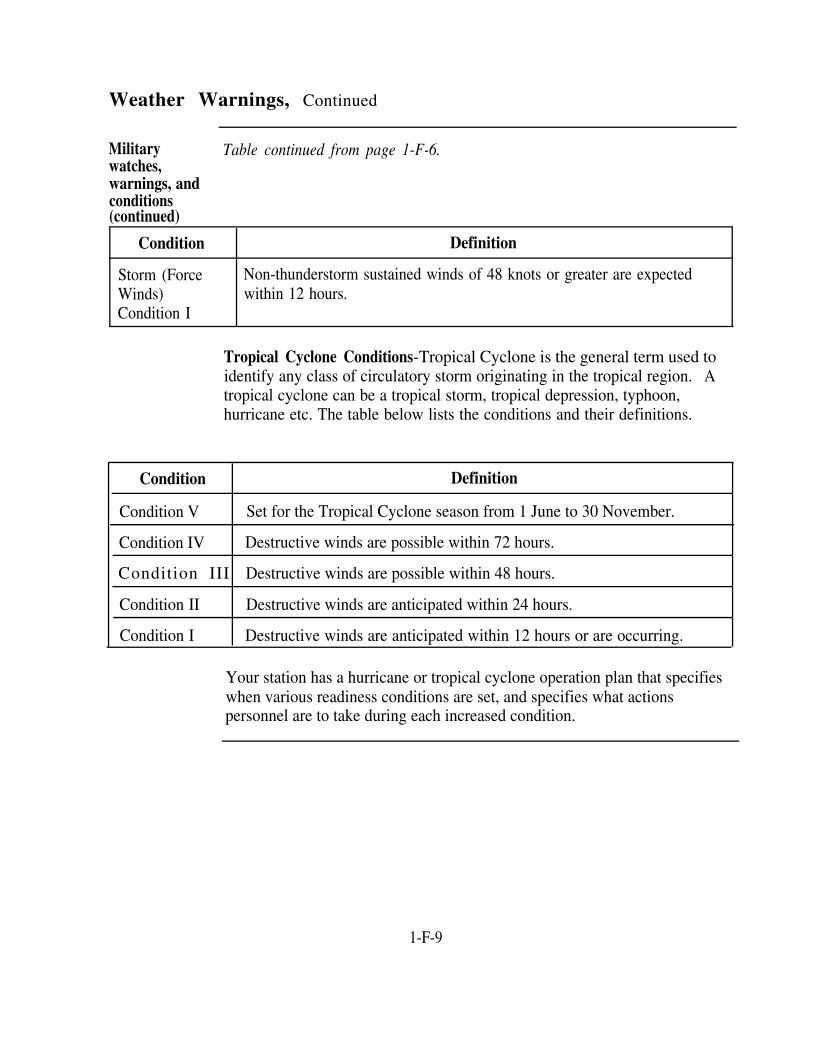
Tropical Cyclone Conditions-Tropical Cyclone is the general term used toidentify any class of circulatory storm originating in the tropical region. Atropical cyclone can be a tropical storm, tropical depression, typhoon,hurricane etc. The table below lists the conditions and their definitions.
Condition Definition
Condition V Set for the Tropical Cyclone season from 1 June to 30 November.
Condition IV Destructive winds are possible within 72 hours.
Condition III Destructive winds are possible within 48 hours.
Condition II Destructive winds are anticipated within 24 hours.
Condition I Destructive winds are anticipated within 12 hours or are occurring.
Your station has a hurricane or tropical cyclone operation plan that specifieswhen various readiness conditions are set, and specifies what actionspersonnel are to take during each increased condition.
1-F-9


CHAPTER 2
AIR NAVIGATION AND AIDS TO AIR NAVIGATION
Overview
Introduction In this chapter, you will be introduced to basic navigation, air navigation, andthe equipment, charts, and publications used to facilitate air navigation.Understanding the above information is an integral part of the knowledgerequired to perform your duties as an air traffic controller. The more you knowabout what goes into planning and completing a successful flight, the betterequipped you are to provide direction and offer assistance. The material in thischapter should give you a basic understanding of the principles of navigation,air navigation, and the aids that are available to assist the pilot in navigating theaircraft from one point to another.
Objectives The material in this chapter will enable you to:
Describe the fundamentals and terms of navigation and the fundamentalsof plotting a position.Describe the different procedures used to plot a position.Identify the various aeronautical charts and publications used in airnavigation, when they are updated, and the factors involved in chartconstruction and design.Describe the basic components, functions, uses, and limitations ofvarious navigational aids as they relate to air traffic control.State the minimum standards required for monitors, monitor facilities,and monitoring of navigational aids (NAVAIDS).
Continued on next page
2-1

Overview, Continued
Acronyms The following table contains a list of acronyms that you must know tounderstand the material in this chapter:
Acronym Meaning
ADF Automatic direction finder
AIM Aeronautical Information Manual
ATC Air traffic control
CH Compass heading
DH Decision height
DME Distance measuring equipment
DOD Department of Defense
ECN Enroute change notice
FAA Federal Aviation Administration
FCCN Foreign clearance change notice
FCG Foreign clearance guide
FLIP Flight information publication
GHz Gigahertz
Hz Hertz
ICAO International Civil Aviation Organization
ICN Interim change notice to the Foreign Clearance Guide
IFR Instrument flight rules
ILS Instrument landing system
Continued on next page
2-2

Overview, Continued
Acronyms(continued)
Table continued from page 2-2.
Acronym Meaning
IM Inner marker, relative to the ILS
IR IFR military training routes
MH Magnetic heading
MHZ Megahertz
MM Middle marker, relative to the ILS
MSL Mean sea level
NAS National airspace system
NAVAID Navigational aid
NDB
NIMA
Nondirectional beacon
National Imagery and Mapping Agency
NOTAM Notice to airmen
OM
PCN
Outer marker, relative to the ILS
Planning change notice
RB Relative bearing
STAR
SID
SR
TACAN
TB
TH
Standard instrument departure
Slow speed low altitude training route
Standard terminal arrival
Tactical air navigation
True bearing
True heading
Continued on next page
2-3

Overview, Continued
Acronyms(continued)
Table continued from page 2-3.
Acronym Meaning
UCN Urgent change notice to FLIP products
UHF Ultra high frequency
UTC Coordinated universal time
VFR
VHF
Visual flight rules
Very high frequency
VOR VHF omnidirectional range
VOT VOR test facility
VR VFR military training route
Z Zulu time
ZD Zone description
Topics This chapter is divided into four sections:
Section Topic See Page
A Basic Concepts of Air Navigation 2-A-1
B Elementary Plotting 2-B-1
C Aeronautical Charts 2-C-1
D Navigational Aids 2-D-1
2-4

Section ABasic Concepts of Air Navigation
Overview
Introduction Navigation is generally defined as the process of directing movement fromone place to another. Air navigation is the process of directing themovement of an aircraft from one point to another. Air navigation hasborrowed and adapted many of the instruments, practices, and procedures ofmarine navigation; thus, basic knowledge and skills are the same for marineand air navigation. In performing your daily duties, you should have anunderstanding of the basic fundamentals of air navigation.
In this section This section covers the following topics:
Topic See Page
Position Determination 2-A-2
Reference Lines on Earth 2-A-4
Direction
Distance
2-A-6
2-A-9
Time 2-A-10
2-A-1

Position Determination
Introduction Regardless of the specific method of navigation, or combination of methods,used by a navigator, the procedures applied must furnish a solution to thethree basic problems of navigation. The three basic problems are:
1. How to determine position
2. How to determine the direction in which to proceed to get from oneposition to another
3. How to determine distance and the related factors of time and speed
Position Of the three problems facing every navigator, determining position,direction, or distance, the most important is determining position. Unless itis known where the aircraft is located, the movements of the aircraft cannotbe directed with accuracy. The term position refers to an identifiablelocation on earth or a point within a man-made system of artificialcoordinates.
We must have a system for designating any position on the surface of earth;therefore, a map or chart is the primary tool used in navigation. Without achart it would be impossible to navigate. It is important to understand certainfacts shown on these charts about earth’s surface. Some of these facts will befamiliar to you and others may not. To ensure that all the facts are knownabout earth’s surface, refer to the table on the following page.
Continued on next page
2-A-2

Position Determination, Continued
Earth facts Before we begin to examine charts, it is important to understand thefollowing facts about earth itself:
Facts about Earth
Earth is not a perfect sphere.
The diameter at the equator equals approximately 6,888 nautical miles.
The polar diameter is approximately 6,865 nautical miles, or 23 miles lessthan the diameter at the equator.
Technically, earth is shaped like an oblate spheroid (a sphere flattened atthe poles).
For the purposes of navigation, we assume that we are working with aperfect sphere. The differences between the two diameters are smallenough to be considered insignificant.
Nautical charts do NOT take earth's oblateness into account.
2-A-3

Reference Lines on Earth
Introduction The location of any point on earth may be defined by using a system ofgeographic coordinates (grid) much like you would use a state or city map.
Geographiccoordinates
The following table contains explanations and definitions used in determiningposition on earth's "grid." The table should help you to understand howposition can be determined for any place on earth.
Term Definition Example
Equator A great circle around the earthdividing the Northern andSouthern hemisphere. Startingline for latitude. A great circle isa circle that is the intersection ofthe surface of a sphere with aplane passing through the centerof the sphere.
Latitude (L) Parallels of latitude (L) are usedto locate points north or southfrom the equator (0° L) to thepoles (90° L). The suffix "north"or "south" is an essential part ofthe description and must alwaysbe included. Parallels of Latitudeare always parallel to the plane ofthe equator.
Prime Meridian A line running from the North toSouth Pole through Greeenwich,England. The starting point forthe measurement of longitude.
Continued on next page
2-A-4

Reference Lines on Earth, Continued
Geographiccoordinates
Table continued from page 2-A-4.
(continued)Term
Longitude
Definition
Meridians of longitude (LO) areused to locate points east andwest. Longitude is based on greatcircles passing through the poles.These great circles are divided inhalf by the poles, with each halfbeing assigned a value of east orwest. Longitude is measured indegrees of arc, from 0° to 180°east or west from the primemeridian. The suffix "east" or"west" is an essential part of thedescription and must always beincluded.
Example
Using a "grid" composed of lines of latitude and longitude superposed over theearth, you can understand how any point or position on earth can be accuratelyplotted.
2-A-5

Direction
Introduction Direction is the second problem of navigation that we will discuss. Direction isdefined as the position of one point in space relative to another withoutreference to the distance between them.
Point system The usual reference point when discussing direction is true north, althoughothers will be used and discussed later in this chapter. The point system forspecifying a direction is not adequate for modern navigation. This system wasused by simply stating the cardinal point of the compass as the direction totravel. The cardinal points of the compass are north, south, east, and west.When you use the point system, these cardinal points are modified to achievegreater accuracy, for example, northeast, north-northwest, southeast etc.
Numericalsystem
Today, we use the numerical system for navigation. The numerical systemdivides the horizon into 360 degrees, starting with north as 000 degrees andcontinuing clockwise through east 090 degrees, south 180 degrees, west 270degrees and back north.
Magneticcompass
As its name implies, the magnetic compass uses the force known as magnetism.Earth has a magnetized core, two magnetic poles, and lines of force that form amagnetic field. Like any other magnet, earth also has a north magnetic poleand a south magnetic pole. Although the poles are placed at specificgeographic sites on magnetic charts, the locations of the magnetic poles changeslightly at times.
As in a magnet, the lines of magnetic force running between the North andSouth Poles create a magnetic field, which affects any magnetic substance. Asa result, a freely suspended magnetic bar or needle tends to align itself withearths lines of magnetic force.
The magnetic compass retains its importance despite the invention of thegyrocompass. While the gyrocompass is an extremely accurate instrument, it ishighly complex, is dependent on an electrical power supply, and is subject tomechanical damage. Conversely, the magnetic compass is entirelyself-contained, fairly simple, and not easily damaged.
Continued on next page
2-A-6

Direction, Continued
Heading Compasses are used to determine heading, which is the angle measureddetermined by clockwise from a reference point to the longitudinal axis of the aircraft.a compass
When the angle is expressed with relation to true north, it is known as trueheading (TH). When it is measured from magnetic north, it is calledmagnetic heading (MIS). And should it be measured from compass north,the term used would be compass heading (CH). In each case, the angle ismeasured in a clockwise direction from the north reference to the longitudinalaxis of the aircraft. You should determine which reference was used, sinceall references do not have the same value. This is done by designating thereference by one of the terms true, magnetic, or compass.
Variation When a magnetized needle is influenced by earth's magnetic field, thedirection it points to is magnetic north. The direction of the geographicNorth Pole is called true north. The angle between magnetic north and truenorth is termed variation. Variation differs at different points on earth.When the needle points to true north, then magnetic north and true northcoincide and the variation is zero. When the needle points east of true north,the variation is east; when the needle points west of true north, the variationis west.
Continued on next page
2-A-7

Direction, Continued
Deviation A compass, however, is affected by all magnetic fields. A piece of iron closeto a compass needle tends to deflect it from magnetic north. Whenever anelectric current passes through a wire, a magnetic field is set up around thewire. The combined effect of all the magnetic fields within the aircraftcauses an error in the compass known as deviation.
Deviation varies as an aircraft changes headings because the metal structureand electrical devices turn with the aircraft, creating a different alignmentrelationship.
Since deviation may vary with each heading, deviation is determined for eachheading that differs by approximately 15 degrees. This is done mostcommonly on the ground by making use of a large compass rose (a largeconcrete area) with magnetic headings inscribed at 15-degree increments.Deviation is checked by comparing the compass reading with the knownmagnetic heading. If deviation is present and the north point of the compasspoints eastward of magnetic north, the deviation is east; if it points westwardof magnetic north, the deviation is west.
NOTE: The sum of variation and deviation is termed compass error.
2-A-8

Distance
Introduction Distance is the spatial separation between two points without regard todirection. In navigation, it is measured by the length of a line on the surfaceof earth from one point to the other.
units ofmeasurement
Obviously, there must be some way to accurately describe the distancetraveled. The customary units are yards, miles, or kilometers. The "mile"used in navigation is the international nautical mile, 6,076 feet, which islonger than the statute mile used in land travel (5,280 feet). Also, 1 minuteof arc on the equator is equal to 1 nautical mile, and 1 minute of arc on ameridian (1 minute of latitude) is equal to 1 nautical mile.
2-A-9

Time
Introduction The consideration of time is always of major importance in the flightplanning process. Almost every planning action is concerned in some waywith the timely arrival at the destination and intermediate fixes en route.
Background To understand the concept of time, we must have a basic knowledge of howtime is derived. In the late 1800s, the development of comparatively rapidtransit systems, such as the railroad and the steamship, made the developmentof an accurate method of keeping time a necessity. The concept that a meansolar day was equal to a theoretical mean sun passing completely aroundearth at the equator once every 24 hours was developed. This concept cameto be widely used for marking the passage of time. One mean solar day is 24hours in length, with each hour consisting of 60 minutes, and each minute,60 seconds.Since the mean sun completes one circuit of earth (360°) every24 hours, it follows that it moves at the rate of 15° of arc as measured at theequator, or 15° of longitude, per hour (360° ÷ 24 = 15°).
Continued on next page
2-A-10

Time, Continued
Zoneidentification
The figure on the following page shows a standard time zone chart of theworld. Each sector appears as a vertical band 15° of longitude in width.Notice that each zone on the chart is defined by the number of hours ofdifference between the time kept within that zone and the time kept within thezone centered on the prime (0°) meridian, passing through Greenwich,England. Each zone is labeled with letters, called time zone indicators,which assist in identification of the zones.
Time based upon the relationship of the mean sun with the prime meridian iscalled UTC. It is also referred to as ZULU time because of its time zoneindicator letter (Z).
The farther to the west of Greenwich that a time zone lies, the earlier will thetime kept in that zone be in relation to UTC. This is indicated by placing aplus (+) sign in front of the hourly difference figure to indicate that thehours must be added to the local zone time to convert it to UTC.to the east of Greenwich a time zone is located, the later its time will berelative to UTC. This is indicated by a minus (-) sign, indicating that thehours must be subtracted to obtain UTC. The Greenwich zone extends 71/2° either side of the prime meridian. A new time zone boundary lies every15° thereafter, across both the Eastern Hemisphere and the WesternHemisphere, resulting in the twenty-fourth zone being split into two halvesby the 180th meridian. The half on the west side of this meridian keeps time12 hours behind UTC, making its difference + 12, while the half on the eastside is -12. These zones are numbered + 1 through + 12 to the west of theGreenwich zone, and -1 through -12 to the east.
Continued on next page
2-A-11
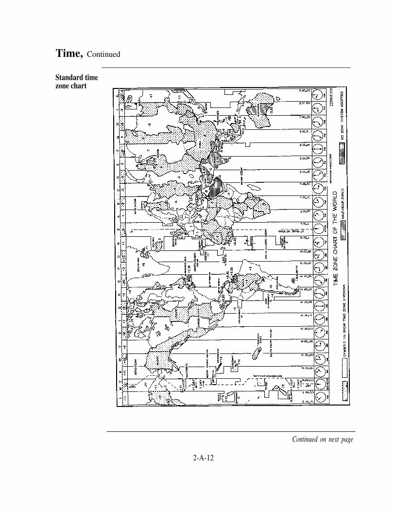
Continued on next page
2-A-12
Time, Continued
Standard timezone chart

Time, Continued
Coordinated The unit of time that you will be working with is UTC. Because UTC isUniversal Time based on scientific computations instead of the rate of rotation and revolution
of earth, the increased accuracy has enhanced air navigation.
Timeconversions
As a general rule, the standard time zone in any particular position on earthcan be found simply by dividing its longitude by 15. When the remainder ofthis division is less than 7 1/2°, the quotient represents the number of thezone; if greater than 7 1/2°, the location is the next zone away from theGreenwich meridian. When there is no remainder, the location lies exactlyon the central meridian of a time zone. The sign of the zone is determinedby the hemisphere in which the position is located. In the WesternHemisphere, the sign is positive (+), and in the Eastern Hemisphere, it isnegative (-).
Applying the proper sign to the number found by division yields the ZD. Ifthe standard time zone where Norfolk, Virginia, is located were required, itslongitude, 76° 18.0' W, would be divided by 15, to yield a quotient of 5 witha remainder of 1°18'. Notice that Norfolk is located in the +5 time zoneand has the time zone indicator letter R assigned.
Time signals Time in the countries of the world is determined by national observatories,such as the U.S. Naval Observatory in Washington, D.C., and the RoyalObservatory in Greenwich, England.
Station WWV, at Fort Collins, Colorado, and station WWVH, on the islandof Kauai in Hawaii, continuously broadcast signals based on NavalObservatory time. These broadcasts may be heard with any ordinary radioreceiver. Complete schedules and information on Navy time signals are inthe Flight Information Handbook.
2-A-13


Section BElementary Plotting
Overview
Introduction Plotting is the primary method of determining geographical position. Whetheryou are working in Air Operations on an aircraft carrier or Base Operations at ashore facility, the principles of plotting are the same. The information in thissection will be useful to you in almost all phases of air traffic control.
In this section This section covers the following topics:
Topic See Page
Plotting Lines of Position 2-B-2
Bearings and Headings 2-B-3
Plotting Aircraft Position Using Radar and TACAN 2-B-5
2-B-1

Plotting Lines of Position
Introduction To understand how a fix or position is determined, you must understand whatlines of position (LOPs) are and how they work.
Lines ofposition
A fix, or accurate position, can be obtained on a chart by finding a specificlandmark. When a NAVAID or radar is not used, each fix is established bytwo or more LOPs. A LOP may be a visible line on the ground, like a highwayor another object of known position, but it is not visible until it is drawn on achart.
To understand how LOP are obtained, let’s first suppose that an aircraft isflying VFR over a railroad, but its location along the length of the railroad isnot known. If the railroad can be located on the chart, a line of position can beestablished. Then, a second railroad that crosses the first is seen and thenlocated on the chart. The exact location of the aircraft along the railroad is nowdetermined. Remember, a fix is an accurate position.
2-B-2

Bearings and Headings
Introduction As an air traffic controller, you need to understand the terms bearing andheading. It is important that you understand the difference between the twoand how they are used to determine LOPs, positions, and fixes.
Headings Earlier in this chapter we talkedabout headings. For the purpose ofthis discussion we will talk aboutTH only. TH is the anglemeasured from true northclockwise to the longitudinal (foreand aft) axis of the aircraft, and itis measured in degrees from 0 to360. The figure shows the aircraftto be on a true heading of 210°.
Bearings There are two forms of bearing, true bearing (TB) and relative bearing (RB).For this discussion, we will talk about the aircraft's bearing relationship to themountain peak depicted in the figures.
Relativebearing
RB is the angle measured from thelongitudinal axis of the aircraftclockwise to a line passing through anobject. Simply put, RB is the positionof an object relative to the nose of theaircraft. For example, if an object wasdirectly behind an aircraft, its relativebearing would be 180° regardless ofthe aircraft's heading. In the example,the mountain peak's relative bearing is070°.
Continued on next page
2-B-3

Bearings and Headings, Continued
True bearings TB is the relation of an object to theaircraft using true north as thereference point instead of theaircraft’s position. TB is usefulwhen the aircraft is turning, and it isdifficult to determine the aircraft’sactual heading. The figure shows thetrue bearing (280°.) of the mountainpeak from the aircraft.
TH, RB, TBrelationship
The relationship between TH, RB, and TB is shown in the figure below.
2-B-4

Plotting Aircraft Position Using Radar and TACAN
Introduction An aircraft can determine its position and obtain a fix by using its airborneradar and TACAN systems.
Radar fix Airborne radar is oriented so that 360° isrepresented by the nose of the aircraft. Byuse of a radarscope in the aircraft, therelative bearing and the distance that theaircraft is from known landmarks can bedetermined, providing a fix. The figure tothe right gives an example of a radar fix foran airborne aircraft.
TACAN fix TACAN provides bearing and distanceinformation. By use of aircraftinstruments, the pilot can determine whatTACAN radial the aircraft is on and itsdistance from the TACAN station. Sincethe position of the TACAN station isknown, a fix, or the aircraft's position,can be determined relative to the TACANstation. The figure to the right shows anexample of a TACAN fix.
2-B-5


Section C
OverviewAeronautical Charts
Introduction The availability of up-to-date aeronautical charts and publications at ATCfacilities is important. Outdated or incorrect publications have been the sourceof numerous aircraft accidents. You are required to possess a thoroughknowledge of the maintenance and use of those charts and publicationsrequired at your facility. The branch chief normally has the responsibility forchart and publication procurement, but all personnel of the branch should beproficient in maintaining and using charts necessary for flight safety.
In this section This section covers the following topics:
NIMA
Topic See Page
2-C-2
Flight Information Publications Program 2-C-4
Miscellaneous Flight Information Products 2-C-8
2-C-1

NIMA
Introduction The NIMA has the overall responsibility for the management and distributionof all DoD navigational charts and publications. The NIMA Order FulfillmentDepartment, Requisition Processing Branch (ISDFR) has several strategicallylocated distribution control points for the distribution of all NIMA products.This branch also responds to inquiries regarding such things as orderingprocedures, product availability, disposition of excess stock, and many otherareas.
Chartinformation
The following table lists some of the more common NIMA products that youwill use in your facility. The table is not a complete list of NIMA products andyour facility may use other NIMA products not listed here.
Product General Information
Catalog of Maps, Charts, and Provides information on the availability and sources of supplyRelated Products, Part I, Vol. I for all aeronautical charts, special-purpose charts, FLIPs, and
related products. It is published semiannually and providesproduct descriptions, chart indexes, ordering procedures, andinformation on Automatic Initial Distribution (AID).
Semiannual Bulletin Digest,Part 1 -Aeronautical Products
This digest is published semiannually. It provides a listing ofnew editions of all aeronautical charts, special purpose charts,and related products. The Semiannual Bulletin Digest alsocontains current editions of charts and publications, itemsbeing deleted, canceled charts and publications, and specialnotices. A new issue of the Semiannual Bulletin Digestreplaces the previous issues and accumulates all changes thathave occurred since the most recently issued digest.
Continued on next page
2-C-2

NIMA, Continued
Chartinformation(continued)
Table continued from page 2-C-2.
Product General Information
Aeronautical Chart Updating Provides the chart-user with a cumulative listing. ofManual (CHUM) significant chart discrepancies that may affect flight safety.
Also provides chart additions and notices of special interestto be considered when using current editions of publishedaeronautical charts. The manual is published semiannuallyand replaces all previous issues of the CHUM Supplementand CHUM
Aeronautical Chart Updating The CHUM Supplement provides the same information asManual (CHUM) Supplement the CHUM but is published on a monthly basis between the
issue months of the CHUM. Each new CHUM Supplementincludes all changes that have occurred since the mostrecently issued CHUM
Automaticinitialdistribution
Automatic Initial Distribution (AID) refers to the automatic issue ofpredetermined quantities of new or revised products. AID is the means bywhich your basic load of maps and charts is kept current with no actionrequired by your command. All products in the NIMA Catalog are availablethrough AID. Each user on AID is required to revalidate their requirementsannually; a listing of requirements is furnished for this purpose.
2-C-3

Flight Information Publications Program
Introduction The Flight Information Publications Program uses the concept that there arebasically three separate phases of flight: flight planning, en route operations,and terminal operations.
FLIP planning The FLIP Planning document is intended primarily for use in groundplanning at base operations offices. It is arranged into four sections: (1)General Planning, (2) Area Planning, (3) Special-Use Airspace, and (4)Military Training Routes, North and South America. These books may berevised between publication dates by issuing a PCN on a scheduled basis or aUCN as required. A PCN or UCN may contain a consolidation of variouschanges and/or corrections to several pages of a book to preclude publishingindividual replacement pages. The following table gives a brief descriptionof the books and charts used in this area:
Book or Chart
General Planning
Description
The General Planning document has general information on allFLIPS, explanations of the divisions of Unites States airspace,terms and abbreviations, operations and firings over the highseas, and aviation weather codes. It also includes informationon flight plans and pilot procedures that have commonworld-wide application, plus information on ICAO procedures.This book is published every 32 weeks with PCNs issued at the16-week midpoint.
Area Planning (AP/1, 2,3, and 4)
AP/1, 2, 3, & 4 books contain planning and procedural datafor specific geographical areas of the world. With theexception of AP/4, these books are published every 24 weekswith PCNs issued at the 8- and 16-week interval points.
Area Planning (AP/1A, AP/1A, 2A, 3A, & 4A books contain information on2A, 3A, and 4A) (Special prohibited, restricted, danger, warning, and alert areas byUse Airspace) country. Military operations and parachute jumping areas are
also listed. These books and AP/4 are published every 48weeks with PCNs at the 16- and 32-week interval points.
NOTE: The AP/4 and AP/4A are combined into one booklet.
Continued on next page
2-C-4

Flight Information Publications Program, Continued
FLIP planning Table continued from page 2-C-4.(continued)
Book or Chart Description
Area Planning (AP/1B) This publication contains information relative to military(Military Training Routes, training routes and refueling tracks for both fixed-wing aircraftNorth and South America) and helicopters. This book is published every 8 weeks.
Charts containing graphic depictions of the IR, VR, SR routesystems throughout the United States and Alaska are alsoincluded.
FLIP enroute FLIP enroute and terminal publications are designed to provide airwayand terminalpublications
structure, radio navigation, approach, and landing information for use duringthe in-flight phase of IFR operations. The DoD Enroute Supplements(IFR/VFR) support these publications with supplemental aerodrome, facility,communication, and procedural information. The table below lists the mostfrequently used FLIP enroute and terminal publications.
Publication Description
Enroute Low Altitude Charts* Enroute Low Altitude charts portray the airway system andrelated data required for IFR operation at altitudes below18,000 MSL. Twenty-eight low altitude charts are availablelabeled L-l through L-28. L-1 through L-26 cover theentire United States; L-27 and L-28 are designed for pilotswho frequently plan flights north and south along the eastcoast.
Enroute High AltitudeCharts*
Enroute High Altitude charts portray the airway system andrelated data required for IFR operations at and above FL180 MSL. Six high altitude charts labeled H-1 through H-6are available, and they can be assembled to form a wallplanning chart for the high altitude airway structure.
Continued on next page
2-C-5

Flight Information Publications Program, Continued
FLIP enroute Table continued from page 2-C-5.and terminalpublications(continued)
Publication
Enroute IFR Supplement*
Enroute VFR Supplement
Flight Information Handbook
Terminal High Altitude*
Terminal Low Altitude*
Description
The Enroute IFR Supplement is a bound booklet containingan alphabetical listing of IFR airports and facilities in theUnited States.
The Enroute VFR Supplement contains an alphabeticallisting of selected United States VFR airports withsketches. This supplement is published every 24 weekswith enroute change notices (ECNs) issued at the 12-weekmidpoint.
The Flight Information Handbook is a DoD publicationissued every 32 weeks. It contains information not subjectto frequent change that is required by DoD aircrews inflight. Sections include emergency procedures, FLIP andNOTAM abbreviations and codes, national andinternational flight data and procedures, conversion tables,standard time signals, and meteorological information.This publication is intended for worldwide use inconjunction with DoD FLIP Enroute Supplements.
Terminal High Altitude publications contain high-altitudeinstrument approach procedures, airport diagrams, SIDs,and radar instrument approach minimums. Terminal HighAltitude information for the United States is published infour booklets.
Terminal Low Altitude publications contain approvedlow-altitude instrument approach procedures, airportdiagrams, SIDs, and radar instrument approach minimums.Terminal Low Altitude information for the United States ispublished in 12 booklets. A terminal change notice (TCN)is issued at the 4-week midpoint.
Continued on next page
2-C-6

Flight Information Publications Program, Continued
FLIP enroute * Charts are issued every 8 weeks with an effective date. Although action isand terminal taken to update this data during the revision cycle, NOTAMS must bepublications(continued)
consulted for the latest information on changing data.
FLIPgeographicareas
FLIP products are produced for the following geographical areas:
AfricaAlaskaCanada and North AtlanticCaribbean and South AmericaEastern Europe and AsiaEurope, North Africa, and Middle EastPacific, Australasia, and AntarcticaUnited States
DAFIF The Digital Aeronautical Flight Information File (DAFIF) providesworldwide digital flight information selected from the DoD FLIP. It is usedfor existing and developing automated applications such as flight planningsystems, flight simulators, and flight management computer systems.
The output media is CD/ROM updated every 28 days. The followingstandard outputs are available:
Full file high and low altitude dataNavigational aids onlyTransaction high and low (changes to previous full-file)
2-C-7

Miscellaneous Flight Information Products
Introduction There are many flight information publications, but we will only discussForeign Clearance Guide, Aeronautical Information Manual, and Notices toAirmen. Also, it is important to remember that this section does not containall of the publications that you may deal with. A more extensive list isprovided in the Flight Planning chapter of the NATOPS Air Traffic ControlFacilities Manual, NAVAIR 00-80T-114. Each facility will have a completelisting of all the publications that they use, and you should becomecompletely familiar with that list.
ForeignClearanceGuide (FCG)
The FCG provides information on aircraft diplomatic clearance and entrancerequirements along with special restrictions and general briefing informationfor all foreign nations, U.S. possessions, and U.S. controlled or administeredareas outside CONUS. Amendments are issued through Interim ChangeNotices (ICNs), Foreign Clearance Change Notices (FCCNs), and revisedbooklets. The FCG general information sections and indexes are issuedannually; revised area booklets are issued each month by specific area on a4-month cycle. FCCNs are issued monthly and contain all permanent andtemporary changes not yet published. ICNs are issued for immediatenotification purposes. The FCG is broken down as follows:
General information sectionCountry index to area bookletsArea booklets
Africa and Southwest AsiaEuropeNorth and South AmericaPacific, South Asia, and Indian Ocean
Index of associated publications
Continued on next page
2-C-8

Miscellaneous Flight Information Products, Continued
Maintainingthe FCG
AeronauticalInformationManual
Airport/FacilityDirectory(AFD)
Some important points concerning the maintenance of the FCG are:
ICNs are transmitted by ROUTINE, PRIORITY, or IMMEDIATEmessage.FCCNs received by mail must be separated upon receipt and reviewed todetermine which ICNs are incorporated.The covers of revised booklets must be read to determine which ICNs andFCCNs are incorporated.
The Aeronautical Information Manual (AIM) is designed to provide theaviation community with basic flight information and ATC procedures foruse in the National Airspace System. You should be familiar with thismanual for ready reference when assisting pilots. It contains a wealth of datarelated to ATC functions. The AIM is complemented by Notices to Airmenand the Airport/Facility Directory publications.
The AIM has information of a relatively permanent nature, such asdescriptions of aeronautical lighting and airport visual aids; descriptions ofvarious navigation aids with proper use procedures; procedures for obtainingweather, preflight, and in-flight services; arrival, departure, and en routeprocedures; emergency procedures; and a pilot and controller glossary. TheAIM is published or revised approximately every 6 months.
The AFD is a 7-volume booklet series that contains data on airports, seaplanebases, heliports, NAVAIDs, communications data, weather data sources,airspace, special notices, parachute jumping areas, and operationalprocedures. These booklets cover the conterminous United States, PuertoRico, and the Virgin Islands.
The AFD also lists data that cannot be readily depicted in graphic form suchas airport hours of operation, types of fuel available, runway widths, andlighting codes. The AFD is published every 56 days.
Continued on next page
2-C-9

Miscellaneous Flight Information Products, Continued
SectionalAeronauticalCharts
VFR TerminalArea Charts(TAC)
U.S. IFR/VFRLow AltitudePlanning Chart
U.S. TerminalProceduresPublication(TPP)
Sectional Charts are designed for visual navigation of slow- to medium-speedaircraft. The topographic information consists of contour lines, shadedrelief, drainage patterns, and an extensive selection of visual checkpoints andlandmarks used for flight under VFR. These charts also include cities andtowns, roads, railroads, and other distinct landmarks. The Sectional Chartsare revised semiannually except that most Alaskan charts are revisedannually.
TACs depict the airspace designated as Class B airspace. These charts aresimilar to sectional charts but have more detail because the chart scale islarger. The TAC is designed for pilots who operate to or from airfieldswithin or near Class B or Class C airspace. TACs are revised semiannuallyexcept Puerto Rico and Virgin Island charts are revised annually.
The IFR/VFR Low Altitude Planning Chart is designed for preflight andenroute flight planning for IFR and VFR flights. This chart depicts lowaltitude airways and mileage, NAVAIDs, airports, special use airspace,cities, time zones, major drainage, a directory of airports with their airspaceclassification, and a mileage table showing great circle distances betweenmajor airports. Planning charts are revised annually.
TPPs are published in 20 volumes covering the conterminous United States,Puerto Rico, and the Virgin Islands. TPPs include:
Instrument Approach Procedure (IAP) ChartsStandard Instrument Departure (SID) ChartsStandard Terminal Arrival (STAR) ChartsAirport Diagrams
Continued on next page
2-C-10

Miscellaneous Flight Information Products, Continued
The DACS is designed to be used with aeronautical charts for flight planningpurposes only—it should not be used as a substitute for a chart. DACS areproduced every 56 days and reflect digitally what is shown on the enroutehigh and low charts. The DACS has nine sections.
DigitalAeronauticalChartSupplement(DACS)
Section 1:Section 2:Section 3:dataSection 4:Section 5:routesSection 6:Section 7:Section 8:Section 9:
High altitude airways, conterminous U.S.Low altitude airways, conterminous U.S.Selected instrument approach procedure, NAVAID, and fix
Military training routesAlaska, Hawaii, Puerto Rico, Bahamas, and selected oceanic
STARsSIDsPreferred IFR routes (low and high altitude)Air route and airport surveillance radar facilities
2-C-11


Section DNavigational Aids
Overview
Introduction
In this section
Various types of air navigation aids are in use today, each serving a specialpurpose in the total system. Although they have varied owners, the FAA hasthe statutory authority to establish, operate, and maintain a common system ofair navigational facilities, and to prescribe standards for the operation of anyaids used for IFR flight in controlled airspace. This common system is referredto as the National Airspace System (NAS).
Knowledge of the basic theory of radio, applicable to both communications andair navigation equipment, increases your understanding of the uses andlimitations of radios and how they interface within the NAS.
This section contains the following tonics.
Topic See Page
Radio Theory 2-D-2
Nondirectional Radio Beacon 2-D-4
VHF/UHF Omnidirectional Ranges 2-D-5
Distance Measuring Equipment 2-D-8
Omniranges, General 2-D-9
Instrument Landing System 2-D-11
Monitoring Navigation Aids 2-D-14
2-D-1

Radio Theory
Introduction To understand the information in this section, it is essential for you to have abasic understanding of radio theory and the principles involved.
Frequency Radiated electromagnetic energy suitable for radio communication is called aHertzian wave. This wave can be represented as a sine curve. The top of thewave represents the maximum positive value, and the bottom represents themaximum negative value. Either maximum may be called a peak. Wavelengthis the distance betweencorresponding points on consecutivewaves, or the distance a wave travelsduring- one cycle. Frequency is thenumber of cycles that occur persecond, stated in terms of hertz andabbreviated Hz; the thousands ofcycles per second, stated in kilohertz,abbreviated kHz; the millions of cycles per second, stated in megahertz,abbreviated MHz; or the billions of cycles per seconds, stated in gigahertz,abbreviated GHz.
The radio frequency spectrum extends from approximately 10 kHz to300,000 GHz.
Frequency range Name of the Range Symbol
30—300 kHz Low frequency LF
300—3,000 kHz Medium frequency MF
3—30 MHz
30—300 MHz
High frequency
Very high frequency
HF
VHF
300—3,000 MHz Ultrahigh frequency UHF
Continued on next page
2-D-2

Radio Theory, Continued
Frequency A Hertzian wave is an oscillating electromagnetic field. A continuous seriesof such waves of like characteristics is called a continuous wave (CW)—viewA. Such a wave can be used inMorse code transmissions, the codebeing keyed so that the signal isinterrupted when desired—view B.A continuous wave may be modifiedwith some characteristics of an audiofrequency signal, such as thatproduced by the human voice. Whenused in this way, it is called a carrierwave. The process of modifying thecarrier wave in this manner is calledmodulation. After this has taken place, the carrier wave may be called amodulated carrier wave—view C. When this form of radio transmission isused, the transmitting station generates the carrier wave and modulates it bythe message to be conveyed. The receiver demodulates the incoming signalby removing the modulating signal and converting it to its original form.
2-D-3

Nondirectional Radio Beacon
Introduction The term NDB is a term that describes a class of homing facility.
Nondirectional Nondirectional indicates that these facilities provide a signal, used forradio beacon homing, equally well in all directions. Homing essentially means that the
pilot is keeping the nose of the aircraft pointed at the radio signal whileproceeding toward the sending facility.
NDBs are intended for use with airborne direction-finding equipment toprovide pilots with bearing information and as approach aids when installedin the vicinity of an airport.
Low- or medium-frequency radio beacons normally operate in the frequencyband of 190 to 535 kHz and transmit a continuous three-letter identificationexcept during voice transmission. Voice transmissions are made on radiobeacons unless the letter "W" (without voice) is included in the classdesignator. UHF NDBs operate in the frequency band of 275 to 287 MHz.
When the radio beacon is installed in conjunction with the ILS marker, it isnormally called a Compass Locator and can be used for navigation atdistances of approximately 15 miles or as authorized in an approachprocedure.
Automatic The ADF is an aircraft radio navigation system that senses and indicates thedirection finder direction to an NDB ground transmitter. Direction is indicated to the pilot as
a magnetic bearing or as a relative bearing to the longitudinal axis of theaircraft, depending on the type of indicator installed in the aircraft.
Limitations of Radio beacons and receiving equipment are subject to atmosphericNDBs disturbances, which can make their use undesirable. The radio compass is
subject to signal fade and static during stormy weather, which can result inerratic indicator operation. This can make NDBs unsuitable for homingapproaches or for holding during thunderstorms. At night, other distantstations interfere with signal reception in the same way as standard radioreceivers. Also, homing normally results in a curved course being flown,rather than a straight course, because of crosswinds acting on the aircraft.
2-D-4

VHF/UHF Omnidirectional Ranges
Introduction
VHFomnidirectionalrange (VOR)
Omni is from the Latin word Omnis, which means "all." An omnifacilityprovides an unlimited number of courses (called radials) in all directions.This is in contrast to the first nationwide system of airway beacons (four-course ranges) which provided guidance in only four directions.
Many different types of omnifacilities are in operation today—the VORfacility, the VOR/DME facility, the TACAN facility, and a facility that usesboth VOR and TACAN called the VORTAC.
The VOR is a radio facility that eliminates many of the difficulties previouslyencountered in air navigation. VOR course information is not affected byweather or other factors common to ADF. With a course indicator, it ispossible to select and precisely fly any one of 360 courses to or from a VOR.
VORs operate on frequencies between 108.0 and 117.95 MHz and are usedby all types of aircraft for navigation and approach guidance. Coursesproduced by VOR facilities compare to the 360° points on a compass. Thesecourses, known as radials, are identified by their magnetic bearing from thestation. Regardless of heading, an aircraft on the 090° radial is physicallylocated due east of the station. When an aircraft flies to the station on thisradial, its magnetic course is 270°. Since the transmitting equipment is inthe VHF band, the signals are free of atmospheric disturbances but aresubject to line-of-sight reception. Reception range varies with the altitude ofthe aircraft. VORs are identified by their Morse code identification or by therecorded automatic voice identification which is always indicated by the useof the word "VOR" following the range’s name. The accuracy of coursealignment of the VOR is excellent, generally ±1°.
VOR/DME Some VOR sites are equipped with a DME feature. The VOR/DME sitefurnishes azimuth information from the VOR and distance information fromthe DME facility. These are two separate types of equipment located at thesame site. A pilot's access to azimuth and distance information from such asite is limited only by the aircraft's equipment.
Continued on next page
2-D-5

VHF/UHF Omnidirectional Ranges, Continued
Tactical airnavigation(TACAN)system
Although VOR was a great improvement over earlier navigational systems, agap still existed in the information presented to the pilot. The TACANsystem was developed to fill this gap by providing the pilot with theinformation needed for precise, geographical fixing of the aircraft position atall times.
TACAN added a continuous display of range information to the courseinformation already available. An integral part of TACAN is DME, whichprovides continuous slant range distance information. Like VOR, TACANprovides 360 courses radiating from the station. Also, because the groundequipment is compact and relatively easy to transport, it provides greaterversatility in installation and mobility than the VOR system.
TACAN operates in the UHF frequency band and has a total of 126 two-waychannels. Air-to-ground frequencies (DME) for these channels are in the1025 to 1150 MHz range, and associated ground-to-air frequencies are in the962 to 1024 MHz and 1151 to 1213 MHz ranges. Channels are spaced at1-MHz intervals in these ranges. The TACAN identifies itself aurallythrough Morse code every 35 seconds.
TACAN ground equipment has either a fixed or mobile transmitting unitcapable of providing bearing information to an unlimited number of aircraft,but is limited to 120 simultaneous replies for distance information. Theairborne unit (interrogator), in conjunction with the ground unit(transponder), reduces the transmitted signal to a visual presentation of bothazimuth and distance information.
TACAN facilities are usually dual-transmitter equipped (one operating andone in standby), fully monitored installations which automatically switch tothe standby transmitter when a malfunction occurs. The monitor is located inthe control tower or radar room and provides a warning when an out-of-tolerance condition exists.
The TACAN system readily lends itself to unique military and navalrequirements and the FAA has integrated TACAN facilities with the civilVOR/DME program. Although the theoretical or technical principles ofoperation of TACAN are quite different from those of the VOR facilities, theend result is the same.
Continued on next page
2-D-6

VHF/UHF Omnidirectional Ranges, Continued
VORTAC Integrated VOR and TACAN facilities are called VORTACs. A VORTACprovides the following services:
VOR azimuthTACAN azimuthTACAN distance (DME)
The VOR and TACAN of a VORTAC system are each identified by a three-letter code transmission. In addition, the VOR and TACAN are assignedpaired frequency channels so that pilots using VOR azimuth with TACANdistance can be assured that both signals being received are from the sameground station.
2-D-7

Distance Measuring Equipment
Introduction The distance from a known ground point is essential information necessary toaccuracy in navigation.
DME The availability of DME to a pilot depends on whether there is DMEassociated with the facility being used and whether the equipment needed ison board the aircraft. The two parts to every DME system are the groundstation, called the transponder, and the airborne portion, called theinterrogator. Inquiries are sent from the interrogator to the transponder,which replies with data that the interrogator can process and display to thepilot as distance from the transponder site. DME operates on theline-of-sight principle and furnishes information with a high degree ofaccuracy. Reliable signals may be received at distances up to 199 nm at line-of-sight altitude with an accuracy of better than 1/2 mile or 3 percent of thedistance, whichever is greater.
DME operates on frequencies in the UHF band between 962 to 1213 MHz.Aircraft equipped with TACAN equipment will receive distance informationfrom a VORTAC automatically, while aircraft equipped with VOR must haveseparate DME equipment.
DME can also be associated with an ILS. The ILS provides the pilot withdistance information from the touchdown point on the runway. In such anarrangement, the DME transponder is located at the ILS glide slope site.
2-D-8

Omniranges, General
Introduction You have probably seen several reasons why omniranges are preferable toNDBs. Three reasons quickly come to mind:
they provide straight courses,they are not subject to atmospheric disturbances, andmore accurate fixing is obtainable.
Through the use of DME, reduced separation standards are possible andholding patterns are tightened up, allowing more air traffic to be compressedinto less airspace. It is now routine for a pilot to maneuver from oneradial/DME fix to another.
The following general information on omniranges will help you become abetter controller through the understanding of the use and limitations of theequipment at hand.
Receptiondistance
Like all VHF/UHFtransmissions, omnirangesignals follow a line-of-sightcourse, which causes anincrease in receptiondistance as the altitude of anaircraft increases. To ensurereception at minimum enroute altitude (1,000 feetabove terrain), omnirangesare spaced sufficiently closetogether to assure navigationcoverage over the airway system.
Classification VOR, VORTAC, and TACAN NAVAIDs are classified according to theiroperational use: (1) terminal—T, (2) low altitude—L, or (3) high altitude—H.The use of the facilities beyond the prescribed limitations may result inunreliable indications in the aircraft. You should refer to Flight Services,FAA 7110.10, and the AIM for specific altitude and distance limitations andassociated clearance limitations.
Continued on next page
2-D-9

Omniranges, General, Continued
VOR receiver The FAA VOR test facility (VOT) transmits a test signal that provides userschecks a convenient means to determine the operational status and accuracy of a
VOR receiver while on the ground where a VOT is located. Airborne use ispermitted. Its use is strictly limited, however, to those areas and altitudesspecifically authorized in the Airport/Facility Directory or appropriatesupplement.
Besides the VOT, naval air stations have checkpoints on a taxiway or ramparea marked to indicate the distance and bearing to the TACAN/VOR.
2-D-10

Instrument Landing System
Introduction The most precise en route navigation system is of little value unless anapproach and landing can be successfully completed at the aircraft'sdestination. Since the early days of instrument flight, approach procedureshave been developed and used with a high degree of safety. The ILSprovides an approach path for exact alignment and descent of an aircraft onfinal approach to a runway.
ILS The ILS ground equipment has two highly directional transmitting systemsand, along the approach, three (or fewer) marker beacons. The directionaltransmitters are known as the localizer and the glide slope transmitter. Thesystem may be divided functionally into three parts:
Information Provided Equipment
Guidance Localizer, glide slope
Range Marker beacon, DME
Visual Approach lights, touchdown and centerline lights,runway lights
Each ILS is categorically classified according to the performance capabilityof the ground equipment. A Category I ILS is capable of providingacceptable guidance information down to a decision height (the point where amissed approach is made if the pilot cannot complete the approach visually)of not less than 200 feet. A Category II ILS is capable of providingacceptable guidance down to a decision height of not less than 100 feet. ACategory III ILS is capable of providing acceptable guidance informationwithout decision-height minima.
Localizertransmitter
The localizer transmitter operates on one of 40 ILS channels within thefrequency range of 108.10 to 111.95 MHz. Identification is in Morse codeand consists of a three-letter identifier preceded by the letter "I". The signalprovides the pilot with course guidance to the runway centerline. Thelocalizer antenna is sited at the far end of the runway so that the center of theantenna is in line with the centerline of the runway. The localizer provides
Continued on next page
2-D-11

Instrument Landing System, Continued
Localizertransmitter(continued)
course guidance throughout the descent path to the runway threshold for adistance of 18 nm from the antenna between an altitude of 1,000 feet abovethe highest terrain along the course line and 4,500 feet above the elevation ofthe antenna site. The course line along the extended centerline in theopposite direction to the front course is called the back course.
Glide slopetransmitter
The glide slope transmitter operates on one of 40 ILS channels within thefrequency range of 329.15 to 335.00 MHz. The glide slope transmitter islocated between 750 and 1,250 feet from the approach end of the runway andis offset 250 to 650 feet from the runway centerline. The glide path featureof the ILS is what makes it a precision approach. The principle of operationis similar to that of the localizer, however, the glide path transmitter providesprecision descent information along the final approach course at the desireddegree of glide slope. The glide path projection angle is normally adjusted to3 degrees above horizontal so that it intersects the MM at 200 feet and theOM at about 1,400 feet above the runway elevation. The glide slope isnormally usable to a distance of 10 nm. Since the glide path signal is sentout the front course only, the back course is not a precision approach andwill have higher minimums.
Markerbeacons
ILS marker beacons have a rated power output of 3 watts or less and arelocated along the ILS approach course. Ordinarily, there are two markerbeacons associated with an ILS: the OM, and the MM. Airports with aCategory II or Category III ILS will also have an IM.
The OM normally indicates a position where an aircraft at the proper altitudewill intercept the glide path on the localizer course. The MM indicates aposition approximately 3,500 feet from the landing threshold. This is alsothe position where an aircraft on glide path will be at an altitude ofapproximately 200 feet above the elevation of the touchdown zone. The IMwill indicate a point where an aircraft is at a designated DH on a glide pathbetween the MM and landing threshold.
Continued on next page
2-D-12

Instrument Landing system, Continued
Compasslocator
A radio beacon used in conjunction with ILS markers is called a compasslocator. This beacon transmits nondirectional signals that are used by pilotsto determine bearings.
The range of a compass locator transmitter is at least 15 miles and is oftenlocated at the ILS MM and OM sites. Compass locators transmit two-letteridentification groups. The outer locator transmits the first two letters of thelocalizer identification group, and the middle locator transmits the last twoletters of the localizer identification group.
2-D-13

Monitoring Navigation Aids
Introduction The most refined of the NAVAIDs is of little value when it is not working.Only when these NAVAIDs are on the air and functioning properly can youand the pilot make use of their data. It is essential that you know the statusof NAVAID equipment at all times.
Remotemonitoring
Each facility that is delegated monitoring responsibility is required tocontinuously monitor a NAVAID that is required or desired to remain on theair. This authority may be delegated to any on-station agency provided that(1) continuous manning is maintained; (2) automatic visual and aural alarmsare installed; (3) maintenance personnel are readily available in the event of amalfunction; and (4) NOTAM responsibilities can be met.
When these conditions can't be met, the periods of operation must bepublished in the appropriate FLIP products, and the NAVAID must bemonitored during those periods. Whenever the NAVAID can't bemonitored, it must be put in a nonradiating status or the identification featuremust be removed.
Site monitoring During flight operations, a NAVAID's operational status must becontinuously monitored. Sometimes the equipment used to monitor theNAVAID's status is located at a site different from its actual location (i.e., ina radar room or control tower cab). When the NAVAID's monitorequipment at a remote site malfunctions and the NAVAID can't be monitoredfrom the remote site, personnel must be sent to the NAVAID's actual site.These personnel monitor the NAVAID's status until the conclusion of flightoperations.
When a NAVAID is monitored at the site, you must ensure that themonitoring equipment is operating properly and that reliable two-waycommunications are available between the site and the primary facility.
2-D-14

CHAPTER 3
MILITARY AIRCRAFT IDENTIFICATION,PERFORMANCE, AND CHARACTERISTICS
Overview
Introduction As an air traffic controller, it is essential that you have an understanding ofaircraft mission, performance, and operating characteristics. This doesn't meanthat you have to be a pilot or have a degree in aeronautical engineering, but abasic understanding will enable you to assist the pilot and possibly prevent youfrom issuing control instructions that the pilot cannot perform. Thisinformation is also an integral part of your planning and execution of controlprocedures. In this chapter, we will discuss the military aircraft that you willmost likely come in contact with as a Navy Air Traffic Controller.
Objectives The material in this chapter will enable the student to:
Identify aircraft by their designations.Recognize aircraft performance and maneuverability capabilities.Recognize aircraft operational characteristics.
Acronyms The following list contains acronyms that you must know to understand thematerial in this chapter:
Acronym Meaning
ATC Air traffic control
fpm
ft
feet per minute
feet
Continued on next gage
3-1

Overview, Continued
Acronyms(continued)
Table continued from page 3-1.
Topics
in. inches
kn knots
MEDEVAC Medical evacuation
mph miles per hour
SAR
VOD
Search and rescue
Vertical onboard delivery
This chapter is divided into three sections:
Section Topic See Page
A Aircraft Designation 3-A-1
B General Aircraft Performance and Characteristics 3-B-1
C Selected Navy Aircraft 3-C-1
3-2

Section AAircraft Designation
Overview
Introduction All aircraft of the Armed Forces have tri-service designations; that is, a givenaircraft bears the same alphanumeric identification symbol whether it is usedby the Navy, Army, or Air Force. The designation system uses a sequenceof letters and numbers to identify aircraft by special status, missionmodification, basic mission, and design modification.
In this section This section covers the following topics:
Topic See Page
Basic Mission 3-A-2
Mission Modification 3-A-3
Special Status 3-A-4
Design and Design Modifications 3-A-5
3-A-1

Basic Mission
Introduction As stated in the overview, all military aircraft have a tri-service alphanumericidentification symbol. One portion of this identification symbol is the basicmission identifier.
Basic missionidentifiers
The basic military designator of an aircraft contains a minimum of a letterand a number with the letter (basic mission identifier) always being first inthe sequence (i.e., C-130, F-14, S-3). The letter indicates the basic missionof the aircraft. The table below lists the basic mission letters used by theArmed Forces and the corresponding mission.
Basic Mission
A
B
C
E
F
H
K
O
Attack
Bomber
Cargo/transport
Special electronicinstallation
Fighter
Helicopter
Tanker
Observation
P
R
S
T
U
V
X
Patrol
Reconnaissance
Antisubmarine
Trainer
Utility
VTOL and STOL
Research
3-A-2

Mission Modification
Introduction A mission modification symbol is used in conjunction with the basic missionidentifier to indicate that the basic mission of the aircraft has been changed ormodified.
Missionmodificationsymbol
When an aircraft is modified from its original mission, a missionmodification letter precedes the basic mission letter. For example:
EA-6KC-130
In the above example, the E represents a special electronic installation on an A-6 and the K indicates an C-130 that is capable of tanking other aircraft. Thefollowing table lists the mission modification symbols and their meanings.
Mission Modification Symbols
A
C
D
E
H
K
L
M
Attack
Cargo
Director (for controllingdrone aircraft or missiles)
Special electronicinstallations
Search and rescue
Tanker
Cold weather plane (arcticor antarctic operations)
Missile carrier
Q
R
S
T
U
V
W
Drone
Reconnaissance
Antisubmarine
Trainer
Utility
Staff
Weather
3-A-3

Special Status
Special statusidentifiers
Occasionally, a letter will prefix the basic mission identifier or missionmodification symbol. This letter prefix is called a special status identifier andindicates the special use of an aircraft. The special status identifiers are listedin the table below.
Special Status
G
J
N
X
Y
Z
Permanently grounded (for instruction and ground trainingpurposes)
Special test, temporary (modified for special testing; uponcompletion of tests, plane will be restored to its original design)
Special test, permanent (permanently modified for testing)
Experimental (not yet adopted for service use)
Prototype (purchases in limited numbers for complete testing ofdesign)
Planning (indicates aircraft is in early stages of planning ordevelopment)
3-A-4

Design and Design Modifications
Design anddesignmodificationsymbols
The number following the basic mission symbol indicates the design number ofthe type of aircraft. The designator F-14 shows an aircraft to be the 14thfighter design. If a particular design is modified, the design number isfollowed by another letter (A, B, C . . . ), the alphabetical order of whichidentifies the number of the modification. For example, the C in E-2C tells usthat the original design of this aircraft has been modified three times. Thefollowing figures show examples of how aircraft designations are used.
3-A-5


Section BGeneral Aircraft Performance and Characteristics
Overview
Introduction To provide service to aircraft under your control, you must know something oftheir characteristics and limitations. This knowledge enables you to appreciatesome of the problems that confront the pilot. It also gives you confidence inyour ability and makes it easier for you to plan ahead.
Often you control several aircraft at once, and it is your responsibility toprovide separation between them. A knowledge of the speed, rate of climb anddescent, rate of turn, and maneuverability of different aircraft is vitallyimportant.
In this section This section will cover the following topics:
Topic See Page
Field Elevation, Temperature, and Humidity 3-B-2
Aircraft Speeds
Aircraft Climb and Descent Rates
Fuel Consumption
3-B-3
3-B-4
3-B-5
3-B-1

Field Elevation, Temperature, and Humidity
Introduction The performance and maneuverability of different aircraft vary since each typeof aircraft has its own set of characteristics governing its performance in the airor on the ground. This performance is affected by field elevation andtemperature.
Effects of fieldelevation,temperature,and humidity
Field elevations and runway temperatures are vital elements in the control of jetaircraft. An example of the effect that altitude has on even a light aircraft iswhen an aircraft that has a rate of climb of 420 fpm at sea level has its rate ofclimb reduced to 225 fpm at 5,000 feet. The distance needed for takeoff isdoubled between these two altitudes.
High temperatures and high humidity have similar effects on aircraftperformance. A high-performance jet fighter quite possibly may not operatefrom an airfield with short runways on a day on which high runwaytemperatures prevail, even though the field elevation is only moderately high.Later in the afternoon or at night, the same fighter may be able to effect atakeoff from the same field because the atmosphere cools and becomes moredense during night hours. More lift is afforded an aircraft in dense air,regardless of aircraft type.
Comparison of takeoff distances with increased altitudes
3-B-2

Aircraft Speeds
Introduction One great concern in air traffic control is aircraft speed. While speeds ofconventional-type aircraft vary, speed differences between conventional and jetaircraft are even greater. You need to be aware of these differences and takethem into consideration.
Traffic pattern Traffic pattern speeds are of primary interest since most of your duties are inspeeds terminal control facilities. A very important portion of the traffic pattern is the
final approach course. That is where most accidents or incidents occur. Theyusually are the result of an incorrect sequencing technique, failure to issuetimely information, or failure to consider approach speeds when a landingsequence is issued.
The following example was an actual incident:
A T-2C was "cleared touch-and-go number one" by the tower. The T-2Cwas executing a normal approach at approximately 93 knots. An instructorpilot in the rear seat of a TA-4J was demonstrating an abeam approachprocedure. The TA-4J was "cleared touch-and-go number two" by thetower. The instructor of the TA-4J heard his or her clearance for touch-and-go but failed to understand that he or she was number two on approach.With both aircraft on final approach, the TA-4J passed directly over the T-2C at about 25 feet. Both aircraft touched down on the runway, the TA-4Jin front of the T-2C, and both lifted off again after their touch-and-golandings. The TA-4J never saw the T-2C.
The two aircraft had dissimilar airspeeds (the TA-4J being much faster) andpattern descent rates. Without getting into all of the rights and wrongs of thecase, let's just take it for the lesson it teaches: due consideration must be givento approach speeds and other operational characteristics when landingsequences are assigned.
3-B-3

Aircraft Climb and Descent Rates
Introduction Air Traffic Controllers often need to direct pilots to make altitude changes tomaintain proper separation between flights. Therefore, you should have someidea of what performance rates are within the capability of certain aircraft.
Climb anddescent rates
Conventional-type aircraft climb/descent rates vary from 500 fpm to 2,000fpm, whereas jets climb/descent rates vary from 3,000 fpm to 5,000 fpm.These rates reflect normal operating ranges, and should not be confused withmaximum performance rates. Air traffic control related factors, such asweather, type of flight, and fuel status, must also be considered when you areanticipating separation based on the normal climb or descent characteristics ofaircraft.
Consider a departure controller directing a departing aircraft to a fix whereexisting conditions require that the aircraft be at a specified altitude beforereaching this fix. If the flight were an air evacuation flight with patientsaboard, its rate of climb would certainly be lessened. The controller shouldrecognize this fact. Instead of "driving" the aircraft straight to the fix, thecontroller should determine, by asking the pilot, if he or she can reach thealtitude, and should be responsive to any request for more climbing time.
It is imperative that you apply good control techniques and judgement and beaware of the operating parameters of the different aircraft that you areresponsible for.
3-B-4

Fuel Consumption
Introduction An important characteristic of jets is their high rate of fuel consumption,especially at low altitudes and while operating on the ground.
Jet fuelconsumption
Ideally, jets should be off the ground as soon as possible after engine startup,especially fighters. Fighter jets normally have a short-range capability, which,when coupled with an air traffic control delay, could hamper their missions.
The fuel consumption rate of jets varies, but the following rule of thumb issuggested as a guideline: a typical jet fighter uses fuel at approximately 100pounds per minute (133.5 pounds equals 20 gallons). Fighter pilots prefer toremain at high altitudes as long as possible, since the fuel consumption rate isgreater at low altitudes and fighters often have little fuel left on arrival at theirdestination. As a controller, you must anticipate such action and plan youractivities to prevent undue delays in handling jet traffic.
Also, local directives may give jets priority over conventional aircraft except inemergencies. Therefore, your job is to adhere to established base trafficpriority procedures as closely as possible, and to help a jet conserve fuel by notunduly delaying its operation. If delay is unavoidable, promptly advise thepilot of the situation.
Minimum fuel Occasionally, you may hear a pilot declare "minimum fuel." "Minimum fuel"indicates that the aircraft's fuel supply has reached the state where the pilot canaccept little or no delay upon reaching the destination. It is not necessary thatyou discontinue other approaches or landings and give "minimum fuel" aircraftpriority, but you should give "minimum fuel" aircraft preference if you have oranticipate a traffic conflict. Always relay "minimum fuel" information to thecontroller to whom control jurisdiction is transferred, if applicable.
Do not confuse a "minimum fuel" report with a "low or emergency fuel"report. A "low or emergency fuel" report is an emergency and should be givenpriority. When the remaining usable fuel supply is so low that traffic priority isneeded to ensure the aircraft's safe landing, the pilot should declare anemergency with ATC and should report, in minutes, the amount of fuelremaining. Always relay "low or emergency fuel" information to the controllerto whom control jurisdiction is transferred, if applicable.
3-B-5


Section CSelected Navy Aircraft
Overview
Introduction The remainder of this chapter deals with Navy aircraft. The list contains themajority of the aircraft you will come in contact with, however, it is not allinclusive. This brief overview should help to familiarize you with many of theaircraft with which you will be working. Keep in mind that memorizing exactfigures is not important, but they are used in this text to show the type ofcomparison that you will make when issuing instructions.
The measurements below are rounded to the nearest inch, and the listedapproach speeds are "average" and can vary.
In this section This section will cover the following topics:
Topic Page Topic Page
T-45 Goshawk
EA-6B Prowler
F/A-18 Hornet
HAR Harrier
F-14 Tomcat
S-3 Viking
P-3 Orion
C-130 Hercules
3-C-2
3-C-3
3-C-4
3-C-5
3-C-6
3-C-7
3-C-8
3-C-9
E-2 Hawkeye
BE-20 Super King Air
T-34 Mentor
H-53 Super Stallion/Sea Dragon
H-60 Seahawk
H-3 Sea King
Remotely OperatedAircraft
3-C-10
3-C-11
3-C-12
3-C-13
3-C-14
3-C-15
3-C-16
3-C-1

T-45 Goshawk
T-45Goshawk
T-45 Goshawk
Wing span
Height
Category
Remarks
30 ft 9 in. Length 39 ft 4 in.
13 ft 4 in. Approach speed 144 mph
III Ceiling 40,000 ft
Manufactured by McDonnell Douglas/British Aerospace.Primary mission is to provide intermediate and advancedstrike fighter training. Is aircraft carrier capable. Isreplacing the TA-4 and the T-2.
3-C-2

EA-6B Prowler
EA-6B Prowler
53 ft
16 ft 3 in.
41,400 ft
III
EA-6B Prowler
Wing span
Height
Ceiling
Category
Remarks
Length
Climb rate
Descent rate
Approach speed
59 ft 10 in.
8,600 fpm
3,000 fpm
126 kn
Manufactured by Grumman Corporation. Carrier- andland-based, twin-engine, mid-wing aircraft. PrimaryNavy mission is electronic warfare (jamming)/specialelectronics.
3-C-3

F/A-18 Hornet
F/A-18 Hornet
Wing span
Height
Approach speed
Category
Remarks
F/A-18 Hornet
37 ft 6 in. Length 56 ft 0 in.
15 ft 3 in. Climb rate 8,000 fpm
141 kn Descent rate 6,000 fpm
III Ceiling 50,000 ft.
Manufactured by McDonnell Douglas Corporation.Carrier- and land-based, twin-engine strike fighteraircraft. Afterburner equipped. The F/A-18A, C, and Eare single seat. The F/A-18B, D, and F are two seat.The F/A-18E and F are based on a lengthened andupgraded design.
3-C-4

HAR Harrier
HARHarrier
HAR Harrier
Wing span
Height
Climb rate
Remarks
30 ft 4 in. Length 46 ft 4 in.
11 ft 7 in. Category III
5,000 fpm Descent rate 8,000 fpm
Manufactured by British Aerospace. The HAR is usedby the Marine Corps as a vertical/short takeoff andlanding (V/STOL) aircraft. Its mission is close support,battlefield interdiction, night attack, and reconnaissance.It is capable of operating from unprepared fields andamphibious assault ships (LHA/LHD).
3-C-5

F-14 Tomcat
F-14 Tomcat
F-14 Tomcat
Wing span 64 ft 1 in. Length 62 ft 8 in.
Height 16 ft 0 in. Climb rate 6,000 fpm
Ceiling 53,000 ft Descent rate 4,000 fpm
Category III Approach speed 135 kn
RemarksManufactured by the Grumman Corporation. Sweepwing design, carrier-based, air superiority fighter, long-range interceptor with attack capability. A two-seat,twin-engine aircraft, it has wings that sweep back forhigh-speed flight. Afterburner equipped.
3-C-6

S-3 Viking
S-3 Viking
S-3 Viking
Wing span 68 ft 8 in. Length 53 ft 4 in.
Height 22 ft 9 in. Climb rate 2,000 fpm
Ceiling 35,000 ft Descent rate 2,000 fpm
Approach speed 116 kn Category III
Manufactured by the Lockheed Corporation. Four-seat,Remarks twin turbofan jet, all-weather, carrier-based undersea
warfare aircraft. Variants perform the tanker (KS-3) andelectronic intelligence (ES-3) missions.
3-C-7

P-3 Orion
P-3 Orion
Wing span
Height
Approach speed
Category
Remarks
P-3 Orion
99 ft 8 in. Length 116 ft 10 in.
33 ft 8 in.
140 knots
I I I
Climb rate
Descent rate
1,850 fpm
2,000 fpm
Ceiling 28,300 ft
Manufactured by Lockheed Corporation. Primarymission is land-based maritime patrol and underseawarfare. The aircraft can operate for over 17 hours ontwo engines. Reversible pitch propellers allow theaircraft to land in a relatively short distance (less than3,000 ft).
3-C-8

C-130 Hercules
C-130 Hercules
C-130 Hercules
Wing span 132 ft 7 in. Length 97 ft 9 in.
Height 38 ft 3 in. Climb rate 1,500 fpm
Approach speed 140 mph Descent rate 1,500 fpm
Category III Ceiling 33,000 ft
RemarksManufactured by the Lockheed Corporation. The C-130is a multimission and tactical transport aircraft with fourengines and a high wing. A rear ramp provides access tothe cargo compartment and can be opened in flight forparachuting troops or equipment. Reversible pitchpropellers allow for very short landing distance.
3-C-9

E-2 Hawkeye
E-2 Hawkeye
E-2 Hawkeye
Wing span 80 ft 7 in. Length 57 ft 6 in.
Height 18 ft 3 in. Climb rate 2,690 fpm
Approach speed 115 kn (E-2C) Descent rate 3,000 fpm
Category III Ceiling 37,000 ft
Manufactured by the Grumman Corporation. Theaircraft mission is to serve as an airborne early warning
Remarks platform and as an airborne platform from which tocontrol aircraft. This carrier-based aircraft is capable oftracking more than 2,000 targets simultaneously andrunning more than 40 intercepts. The radome above therear fuselage measures 24 feet in diameter.
3-C-10

BE-20 Super King Air
BE-20 SuperKing Air
BE-20 Super King Air
Wing span 54 ft 6 in. Length 43 ft 9 in.
Height 15 ft 0 in. Climb rate 2,450 fpm
Ceiling 35,000 ft Descent rate 2,500 fpm
Category II
Remarks Manufactured by the Beech Aircraft Corporation.Primary Navy mission is passenger/cargo transport.Twin turboprop engines mounted far forward on the lowwing. T-tail configuration.
3-C-11

T-34 Mentor
T-34 Mentor
T-34 Mentor
Wing span 33 ft 3 in.
Height 9 ft 7 in.
Approach speed 120 mph
Category I
Length 28 ft 8 in.
Climb rate 1,150 fpm
Descent rate 1,150 fpm
35,000 ftCeiling
RemarksManufactured by Beech Aircraft Corporation. Two-seatturboprop used for primary flight training, recruiting, andtarget spotting for strike fighter aircraft. Not carriercapable.
3-C-12

H-53 Super Stallion/Sea Dragon
H-53 SuperStallion/SeaDragon
H-53 Super Stallion Sea Dragon
Fuselage width
Height
Climb rate
Category
Remarks
8 ft 10 in. Length 73 ft 4 in.
17 ft 5 in. Max speed 196 mph
1,500 fpm Descent rate 1,500 fpm
I Ceiling 18,500 ft
Manufactured by Sikorsky Aircraft. Navy uses the CH-53E Super Stallion for VOD and recovery of damagedaircraft from aircraft carriers and the MH-53E SeaDragon for mine countermeasures. Marine Corps usesthe CH-53E for amphibious assault, heavy equipmentand armament transport, and disabled aircraft recovery.Over 1,200-mile maximum range. Generates significantwake turbulence and rotor wash.
3-C-13

H-60 Seahawk
H-60 Seahawk
H-60 Seahawk
Width
Height
Climb rate
Category
Remarks
10 ft 8 in. Length 40 ft 11 in.
12 ft 5 in. Max speed 169 mph
2,000 fpm Descent rate 2,000 fpm
I
Manufactured by Sikorsky Aircraft. Primary mission isundersea warfare and antiship surveillance and targeting.Also provides SAR, MEDEVAC, planeguard, and VOD.Landing gear is non-retractable. SH-60B is embarked oncruisers, destroyers, and frigates in two-planedetachments from HSL squadrons. SH-60F is combinedwith two HH-60Hs in six-plane HS squadrons aboardaircraft carriers. Range is 150 nm with 1-hour loiter.
3-C-14

H-3 Sea King
H-3 Sea King
Main rotordiameter
Height
Climb rate
Ceiling
Remarks
H-3 Sea King
62 ft 0 in.
15 ft 6 in.
1,500 fpm
14,700 ft
Length 72 ft 8 in.
Max speed 166 mph
Descent rate 1,500 fpm
Category I
Manufactured by Sikorsky Aircraft. Previously theNavy’s standard carrier-based undersea warfarehelicopter. Replaced by SH-60. Now flown only in theutility and VIP roles. Maximum range at optimumconditions is 625 miles.
3-C-15

Remotely Operated Aircraft
Introduction As a Navy air traffic controller, you may be assigned to an ATC facility thatdeals with remotely operated aircraft (ROAs). Specific operating proceduressuch as submission of flight schedules, weather minimums, course rules, andapplicable air traffic control procedures should be outlined in local AirOperations Manuals or facility directives. Also, these type of aircraft havedifferent designations such as remotely operated aircraft (ROAs), unmanned airvehicle (UAV), and so forth.
Control station Two-way radio communications must be established between the ROA controlstation and the appropriate ATC facility before takeoff and during the durationof the aircraft flight.
ROA operating Because ROAs are remotely controlled, specific areas ( i.e., exclusive useareas restricted areas) are normally established for their test flights. These aircraft fly
profiles designed to meet particular test criteria. Flight outside these profiles isnormally restricted to:
transitioning to or from the profile,entry into the landing pattern, orproceeding to a pre-designated ditching area under emergency conditions.
Equipmentrequirements
ROAs have extended range capability but are limited in their ability to "see andavoid" other traffic. Therefore, certain equipment requirements are normallyestablished for ROA operations such as:
Fully operational primary and secondary control links,Operating IFF transponder or beacon tracking system,Operational collision avoidance lighting,Operating tracking system, andOperational "auto pilot" return home feature.
3-C-16

CHAPTER 4
AIRPORT LIGHTING, MARKINGS, AND EQUIPMENT
Overview
Introduction As an Air Traffic Controller, you must have a thorough knowledge of theairport layout, airfield markings, and airfield lighting equipment to effectivelycontrol aircraft and vehicular traffic on and in the vicinity of the airport. Theinformation in this chapter will give you a basic understanding and enable youto make sound decisions based on your airfield's capabilities. This chapterdoes not cover everything with which you might possibly come in contact.Since improvements and new equipment come out all the time, make sure thatyou keep current with the equipment and changes at your airfield.
Objectives The material in this chapter will enable you to:
Identify standard airport markings.Identify the standards applicable to airfield lightings systems andindicate the functions of and operating rules for related components.Identify the different types of emergency recovery equipment and theiruses.
Acronyms The following table contains a list of acronyms that you must know tounderstand the material in this chanter:
Acronym
AICUZ
Meaning
Air installations compatible use zones
ARFF Aircraft rescue and firefighting
ATC
ATCF
Air traffic control
Air traffic control facility
EOD
FAAExplosive ordnance disposal
Federal Aviation Administration
Continued on next page
4-1

Overview, Continued
Acronyms(continued)
Table continued from page 4-1.
Acronym Meaning
FAR Federal Aviation Regulation
FCLP
GCA
Field carrier landing practice
Ground controlled approach
HIRL High intensity runway lights
IFR Instrument flight rules
ILS
LIRL
Instrument landing system
Low intensity runway lights
MIRL Medium intensity runway lights
OLS
PAPI
Optical landing system
Precision approach path indicator
RCLS Runway centerline lighting system
REIL Runway end identifier lights
TACAN Tactical air navigation
TDZL Touchdown zone lighting
VASI Visual approach slope indicator
VFR Visual flight rules
VOR VHF Omnidirectional range
Continued on next page
4-2

Overview, Continued
Topics This chapter is divided into three sections:
Section Topic See Page
A Airport Layout 4-A-1
B Airfield Lighting Systems and Operations 4-B-1
C Miscellaneous Airfield Equipment and Emergency 4-C-1Systems
4-3


Section AAirport Layout
Overview
Introduction The layout of each airport is unique. It is important that you become familiarwith the location and function of all the different areas of your airfield. Thebetter you know the layout of your airfield, the better service you canprovide.
In this section This section covers the following topics:
Topic See Page
Airfield Facilities
Runway Markings
4-A-2
4-A-5
Taxiway Markings 4-A-9
Closed, Hazardous, and Other Area Markings 4-A-11
4-A-1

Airfield Facilities
Introduction The Facility Planning Criteria for Navy and Marine Corps ShoreInstallations, NAVFAC P-80, provides planning criteria for determining therequirements for shore-based facilities needed to support fleet and MarineCorps operations. NAVFAC P-80 was written with several purposes inmind. One purpose was to ensure that the existing and planned facilities areneither too small nor too large to accomplish mission objectives. Anotherpurpose was to establish common planning standards within the Navy andother services.
Runways Runways are paved surfaces for the landing and takeoff of aircraft. Thenumber of runways required is determined by the expected traffic density,airfield mission, operational procedures, and environmental factors. Runwayorientation is determined by the analysis of wind data, terrain, noise levels,and planned local development.
Runway classification is dependent on the types of aircraft that operate fromthe runway and is not related to aircraft approach categories. Class Arunways are used primarily for small aircraft operations; they don’t have thepotential for, or foreseeable requirement for, use by heavier aircraft. ClassA runways are less than 8,000 feet long and less than 10 percent of theoperations involve Class B type aircraft. All other runways are Class Brunways except the basic training outlying fields used by T-34 aircraft forwhich special criteria apply.
The standard width for runways built before June of 1981 is 200 feet. Afterthis date, the standard width is normally 75 feet for Class A runways and 200feet for Class B runways. For detailed runway specifications and widthexceptions refer to Facility Planning Criteria for Navy and Marine CorpsShore Installations, NAVFAC P-80.
AICUZ The classification of Navy and Marine corps runways is determined as a partof the Air Installations Compatibility Use Zones (AICUZ) program. Thisprogram, which is defined in Air Installations Compatibility Use Zones(AICUZ) Program, OPNAVINST 11010.36, provides guidelines forachieving compatibility between air installations and neighboringcommunities. Each Navy air installation designated by the Chief of NavalOperations has an Air Installations Compatibility Use Zones (AICUZ) study.
Continued on next page
4-A-2

Airfield Facilities, Continued
AICUZ(continued)
Runwayoverrun areas
Taxiways
This study includes a detailed analysis of aircraft noise, accident potential,land-use compatibility, operational alternatives, and potential solutions toboth existing and potential land-use problems. The foundation of the AICUZprogram is an active local command effort to work with local communities toprevent incompatible development of land adjacent to military airfields.
The primary purpose of runway overrun areas is to provide a reasonablyeffective deceleration area for aborting or overshooting aircraft. This areamay also serve as an emergency all-weather access for fire-fighting, crash,and rescue equipment.
Some runways have paved overruns; these areas are marked with yellowchevrons across them. An area with this type of marking is unusable forlanding, takeoff, and taxiing.
Taxiways are paved surfaces on which aircraft move under their own powerto and from landing, service, and parking areas. Taxiway length dependsupon the specific airfield configuration and layout of support facilities.Taxiways are normally 75 feet wide except for the taxiways that support onlyclass A runways or helicopter landing pavements. Those taxiways are only40 feet wide.
End turn-offs are planned for each Class B runway end and are 150 feet wideexcept those from parallel runways to the parallel taxiway. End turn-offsfrom parallel runways to the parallel taxiway are 200 feet wide. Normalintermediate turn-offs are required for all Class B runways. Normalintermediate turn-offs for Class B runways are 75 feet wide and are placed2,000 feet from each end of the runway and in the remaining runway lengthat intervals of not more than 3,000 feet or less than 2,000 feet. High-speedturn-offs are provided where traffic studies indicate the requirement. High-speed turn-offs are 100 feet wide at the throat tapering to 75 feet and are aminimum of 1,000 feet long.
Taxiways are located to provide adequate clearance between taxiing aircraft,aircraft in adjacent areas, and other obstacles.
Continued on next page
4-A-3

Airfield Facilities, Continued
Parking aprons Parking aprons are required for parking, servicing, loading, and unloadingaircraft. They are connected to the runways by taxiways or tow ways.There is no standard size or configuration for parking aprons. Parking apronsizes are based on the type and number of aircraft to be parked, therequirement for squadron integrity, and 45 versus 90 degree parking. Thearea required includes:
parking space,wing-tip separation between aircraft,interior taxilanes, andperipheral taxilanes.
Compass An aircraft compass calibration pad is a paved area in a magnetically quietcalibration pad area where the aircraft compass is calibrated. A minimum of one compass
calibration pad is provided at each airport; however, additional pads may berequired depending on local demands.
The pad surface is marked every 15 degrees to indicate magnetic bearingsbeginning with magnetic north. Thetaxiway to the compass rose is generallyplaced perpendicular to the taxiway withthe least traffic. Brass or bronze is used inthe construction of a compass rose sinceneither metal affects magnetic instruments.Other metal objects should be kept clear ofthe pad when the compass rose is in use.In the calibration of an aircraft compass,all electrical equipment is turned on andthe engines are kept running to simulateactual flight conditions.
4-A-4

Runway Markings
Introduction Airfield pavement markings are regulated by Federal Aviation Administrationwith overall Navy configuration control established by NAVAIRSYSCOM.The following information complies with current facility-design manuals andmay differ slightly for some facilities built many years ago; however, futureconstruction and modernization of existing facilities will meet theserequirements. Airfield marking and lighting requirements for Navy andMarine Corps can be found in General Requirements for Shorebased AirfieldMarking and Lighting, NAVAIR 51-50AAA-2.
Runwaydesignationmarkings
Runways are numbered according to their inbound magnetic heading,rounded off to the nearest 10 degrees. The runway number is the wholenumber nearest one-tenth the magnetic azimuth of the centerline of therunway. If the magnetic azimuth of the runway centerline is 5 degrees ormore, the designation is the next higher number. If the whole number is lessthan 10, the runway designation number is preceded by a 0. For example:
A runway centerline with a magnetic azimuth of 186 degrees will have thenumber 19 painted on the runway approach end. The whole number 186is rounded to 190, and the zero is dropped.The opposite end of this runway will have a 01 painted on the runwayapproach end. The whole number 006 is rounded to 010, and the zero isdropped.
At airports that are using parallel runways, L indicates left, R indicates right,and C indicates center. All numbers and letters are painted retroreflectivewhite.
Runwaycenterlinemarkings
Runway centerline markings consist of a broken line of 100- to 150-foot-longstripes separated by 60-foot minimum blank spaces. The first centerlinestripe starts 40 feet from the top of the runway designation marking. Thecenterline stripes are 12 to 18 inches wide for basic runways and a minimumof 36 inches wide for other runways. Runway centerline markings areretroreflective white in color.
Continued on next page
4-A-5

Runway Markings, Continued
Other runway The table that follows contains other runway markings that you should bemarkings familiar with.
Marking or Marker Description Example
Precision approach Runway side stripes are painted oninstrument runway the precision instrument runway tomarkings further aid takeoff and landing
guidance.
Runway thresholdmarkings
Runways 200 feet wide have 10stripes marking the landingthreshold, each 12 feet wide by 150feet long. These stripes areseparated by 3 feet except for themiddle space, which has 16 feetbetween stripes. For all thresholdmarkings, the color isretroreflective white.
Displaced threshold Yellow arrows 120 feet long, withmarkings 80-foot spacing between the
arrows, are painted on the unusedend of the runway pavement andpoint to the displaced thresholdmarkings. Four yellow chevronsare also located on the approachside and point at a solid whitetransverse stripe. Displacedthreshold markings are painted withnonretroreflective paint.
Continued on next page
4-A-6

Runway Markings, Continued
Other runway Table continued from page 4-A-6.markings(continued)
Marking or Marker
Runway distancemarkers
Description
Runway distance markers consist ofa row of black and white verticalmarkers (signs) along each side ofthe runway that are spaced 1,000feet longitudinally to inform pilotsof the distance remaining on therunway in thousands of feet. Theedges of the markers nearest therunway in each row must form a linenot less than 50 feet and not morethan 75 feet from the full-strengthrunway edge. The markers must notbe less than 50 feet from the edge ofany intersecting runway or taxiway.
Example
Continued on next page
4-A-7

Runway Markings, Continued
Arresting gear Arresting gear signs on both sides of the runway mark the location of arrestingsigns and gear. These signs have large yellow circles on a black background. Also, amarkings series of 10-foot-diameter retroreflective yellow disks that are painted in a line
across the runway mark the location of the arresting gear pendant cable.
4-A-8

Taxiway Markings
Introduction Taxiway markings are similar to runway markings and are regulated like otherairfield pavement markings.
Taxiwaycenterlinemarkings
Taxiway centerline markings consist of a continuous retroreflective yellowstripe not less than 6 inches wide along the taxiway axis. These markingsprovide taxiway identification and longitudinal guidance for steering theaircraft.
Standardholding positionmarkings
Standard holding position markings are painted with retroreflective yellowpaint and consist of two solid lines and two dashed lines that are 6 inches wide.They are placed across the taxiway at right angles to the taxiway centerline.When the taxiway is associated with a warmup pad, however, the holding linemay be parallel to the centerline of the runway or taxiway that is intersected.These markings are used for holding aircraftat least 175 feet (250 feet preferred) clear ofthe nearest runway edge. Ground trafficmust not proceed beyond the holding linemarking without a control tower clearance.Category II holding position markingsconsist of two parallel solid lines withdouble connecting lines at 10-foot intervals,located not less than 400 feet from therunway centerline.
Continued on next page
4-A-9

Taxiway Markings, Continued
TACANcheckpointmarkings
alignment, crosses the circle and extendsoutside the circle for 20 feet. The arrow is1 foot wide, and the arrowhead is 6 feetlong and 3 feet wide. The arrow is omittedwhen aircraft alignment is not required.
TACAN checkpoint markings are located on the taxiway centerline near therunway threshold. A 20-foot-diameter circle on the taxiway centerline markseach checkpoint. The circle marking stripeis nonretroreflective yellow and is 12inches wide. A nonretroreflective yellowarrow, used by the pilot for aircraft
TACAN TACAN checkpoint signs are used in conjunction with TACAN checkpointcheckpoint sign markings. The pilot uses the information that the checkpoint sign provides
when verifying the operation of a NAVAID in his or her aircraft beforetakeoff. The sign is placed at least 25 feet from the edge of the taxiway andnot less than 200 feet from the runway edge. The sign is normally located onthe same side of the taxiway as the turn onto the runway. The sign informsthe pilot of the identification code and type of NAVAID, radio channel,magnetic bearing, and the distance in nautical miles to the transmittingantenna from the checkpoint. The sign has black characters on a yellowbackground.
4-A-10

Closed, Hazardous, and Other Area Markings
Introduction Where an operational requirement exists, there are provisions for markingclosed, hazardous, and other airport areas.
Closed area A closed area may be a runway, taxiway, or any other movement area (forexample, parking apron) that was once used but is no longer consideredusable. It may be a temporary condition, such as during construction, orpermanently closed.
Closed runwaymarkings
Closed taxiwaymarkings
Closed runways are marked with crosses at each end, near the entrances tointersecting active runways and taxiways, and at intervals not greater than1,000 feet. The crosses are painted with nonretroreflective yellow paint.The arms of the crosses intersect at right angles and are 10 feet wide and 60feet in overall length.
Closed taxiways are marked with crosses ateach end and at potential entrances andintersections with active runways ortaxiways. Crosses also appear at intervalsnot greater than 1,000 feet apart along theclosed length. These crosses are paintedwith nonretroreflective yellow paint. Thearms of the crosses intersect at right anglesand are not less than 5 feet wide and 30 feetin overall length.
Continued on next page
4-A-11

Closed, Hazardous, and Other Area Markings, Continued
Hazardous area Hazardous or failed areas of a taxiway are marked to preclude aircraft frommarkings taxiing on them. The hazardous area on the traffic side of the taxiway is
outlined with a pair of parallel retroflective yellow lines. The area shouldalso be outlined with yellow or orange rectangular flags not less than 18inches on each side. Orange or orange and white cones can also be used.Flags and cones should be 30 inches or less in height.
Runwayoverrunmarkings
Paved overrun areas could easily be mistaken for a landing area. Therefore,runway overrun markings are used on them. These markings are in theshape of a chevron or partial chevron and are painted with nonretroreflectiveyellow paint. The apex of each chevron is at the runway centerline and eachchevron leg makes an angle of 45 degrees to the centerline. The chevronsare equally spaced at 100-foot intervals through the paved overrun area. Thelegs of the chevrons are 3 feet wide and extend out to the edge of the pavedarea but not more than 100 feet on each side of the centerline.
Continued on next page
4-A-12

Closed, Hazardous, and Other Area Markings, Continued
Runwayshouldermarkings
Runway shoulder markings consist of diagonal stripes at 45 degrees to therunway edges uniformly spaced at 100-foot intervals. These stripes shouldpoint away from the runway ends with the change in direction at the runwaymidpoint. Runway shoulder markings are painted with nonretroreflectiveyellow paint. The stripes are 3 feet wide and extend at least 10 feet from therunway edge.
Continued on next page
4-A-13

Closed, Hazardous, and Other Area Markings, Continued
Taxiwayshouldermarkings
Taxiway shoulder markings consist of bars perpendicular to the taxiing areaedge. On straight taxiway segments, the bars are spaced along the edge notmore than 100 feet apart. On curved taxiway segments, the bars are spacedalong the edge not more than 50 feet apart. Taxiway shoulder markings arepainted with nonretroreflective yellow paint. The bars are at least 3 feetwide and are 25 feet long or to within 5 feet of the outer edge of the shoulderpaving, whichever is less.
Continued on next page
4-A-14

Closed, Hazardous, and Other Markings, Continued
Overhead view The figure below shows an overhead view of an airfield and its markings andmarkers. For more information concerning airport markings and markersrefer to General Requirements for Shorebased Airfield Marking and Lighting,NAVAIR 51-50AAA-2.
Carrier deckmarking
Those naval air stations that train pilots ashore for landing aircraft on carriers atsea are equipped with a simulated carrier deck on runway ends selected forFCLP. The carrier deck's placement is dependent on the location of the OLS.Carrier deck markings consist of centerline, edge, and ramp athwartshipmarkings. The markings are nonretroreflective white except for the alternatingsections of the centerline markings that are nonretroreflective yellow. Carrierdeck markings supersede runway markings in areas where they conflict. Thecarrier deck centerline is parallel to and left of the runway centerline. Thelength of the simulated carrier deck is 778 feet.
4-A-15


Section BAirfield Lighting Systems and Operations
Overview
Introduction Airport lighting systems are standardized by the Air Force, Navy, and the FAAto present a uniform and unmistakable appearance. These standards specify thelocation, spacing, and color of lighting components in use. Flight personnelfamiliar with the standards can readily interpret the lighting aids at any airfield.
An airfield lighting system consists of runway lighting and other lighting aidsalong with their controls and power supplies. The major lighting aids thatcould be installed to support an airport's mission are considered in this section.
Procedure Procedures for the operation of airport lighting are in Air Traffic Control, FAAOrder 7110.65. Operation of airport lighting at controlled airports is normallythe responsibility of the tower. When the airfield is closed, all associatedlighting is shut down with the following exceptions:
Navigable airspace obstruction lights as outlined in FAR, Part 77, thatare not associated with the closed airportRotating beacons if used as navigation reference points or visuallandmarks
Since the airport lighting system is controlled from the tower, you must knowhow and when to operate the various components. You might think that youturn everything on at sunset and off at sunrise, but this is not the case.
In this section This section covers the following topics:
Topic See Page
Aeronautical Beacons 4-B-2
Runway Lighting 4-B-5
Miscellaneous Airport Lighting 4-B-9
4-B-1

Aeronautical Beacons
Introduction The aeronautical beacon is a visual aid. Beacons indicate the location of anairport, a landmark, a hazard, or an obstruction to air navigation. The principallight in a beacon rotates or flashes and is of relatively high intensity.
The color or color combination displayed by a particular beacon indicateswhether the beacon marks a landing place, a landmark, a hazard, or obstruction.The common types of beacons are the airport rotating beacon, the identificationor code beacon, and the hazard or obstruction beacons.
Airportrotatingbeacons
An airport rotating beacon is required at each airfield unless adjacent airfieldsshare a common beacon. The following table contains pertinent facts aboutairport rotating beacons:
Airport Rotating Beacon Facts
Rotation Rotation is 6 revolutions per minute and in a clockwise direction whenviewed from above. Is always rotated at a constant speed, which producesthe visual effect of flashes at regular intervals. Flashes may be alternatelygiven as one color or two colors. The signal from the beacon must bevisible for 360 degrees.
Location Located not less than 1,000 feet from the centerline or centerline extendedfrom the nearest runway and not more than 5,000 feet from the nearestpoint of the usable landing area. Is located 750 feet or more from thecontrol tower. Base must be at least 20 feet higher than the elevation ofthe floor of the tower cab.
Continued on next page
4-B-2

Aeronautical Beacons, Continued
Airportrotatingbeacons
Table continued from page 4-B-2.
(continued)
Operation An airport rotating beacon is operated as follows:
Color scheme
Airport Rotating Beacon Facts
Sunset to sunrise-Continuously during airfield operationsSunrise to sunset-When the reported ceiling or visibility is below basicVFR minimums
The colors and color combinations of lights for rotating beacons and theirmeanings are as follows:
A lighted land military airport–Alternating dual peaked (two quick)white between green flashesA lighted land civilian airport–Alternating white and greenA lighted water airport–Alternating white and yellow
Identification An identification or code beacon is required when the airport rotating beacon isor code beacon more than 5,000 feet from the nearest runway or where the rotating beacon
serves more than one airfield.
This beacon is a nonrotating flashing omni-directional light visible through 360degrees. The identification or code beacon flashes a color-coded signal atapproximately 40 flashes per minute. The signal is assigned a code ofcharacters to identify a particular airfield. The identification beacon shall beoperated whenever the associated airport rotating beacon is operated.
Continued on next page
4-B-3

Aeronautical Beacons, Continued
Obstructionlighting
Obstruction lighting consists of flashing and steady-burning red lights.Extremely tall structures require high-intensity strobe lights during both dayand night. Obstruction lights are used to define the vertical and horizontallimits of objects that are hazardous to aircraft operation. These obstructionobjects include permanent construction hazards, natural hazards, fixedequipment, and all installations that encroach on the standard airfieldclearance surfaces. When repair or construction constitutes a temporaryhazard to air navigation, these areas must be adequately lighted withtemporary obstruction lights.
Obstructions are defined as those objects that penetrate the imaginarysurfaces defined in Airfield Safety Clearances, NAVFAC P-80.3. Therequirements for lighting obstructions and other hazards to air navigation areset forth in the General Requirements for Shorebased Airfield Marking andLighting, NAVAIR 51-50AAA-2.
4-B-4

Runway Lighting
Introduction Various runway lights are installed at airports to provide visual guidance atnight and under low-visibility conditions for aircraft during takeoff andlanding.
Runway lightsystemclassifications
Runway light systems are classified according to the intensity or brightnessthat they produce; they are high-intensity runway lights (HIRLs),medium-intensity runway lights (MIRLs), and low-intensity runway lights(LIRLs). Navy requirements indicate that HIRLs shall be used for all newrunway edge lighting installations and should be considered for replacementor improvements of existing runway edge lighting systems.
Runway edge Runway edge lights form the outline of the runway for night operations orlights during periods of reduced visibility. These lights are on both sides of the
runway, extending the entire length. Runway edge lights are spaced amaximum of 200 feet apart. Runway edge lights are bidirectional whitelights. The last 2,000 feet of the runway or one-half of the runway length,whichever is less, is displayed by the lights as aviation yellow on instrumentrunways. Except at intersections where semiflush runway edge lights areused to maintain uniform spacing or within the area of the arresting gear tapesweep, runway edge lights are elevated.
Thresholdlights
Threshold lights are installed to provide positive identification of thebeginning of the operational runway surface for approaching aircraft at nightor during periods of reduced visibility. Threshold lights are installed in astraight line at the end of each runway perpendicular to the runwaycenterline. The outboard lights are unidirectional (toward the aircraftapproach path) green lights. The inboard lights are green but may bebidirectional with red beams (toward the runway) for runway end lights.Threshold lights are connected to and form an integral part of the runwayedge light circuit.
Runway endidentificationlights
Runway end identification (identifier) lights (REIL) provide the pilot withrapid and positive identification of the runway threshold during an approachfor landing. REILs are effective for overriding surrounding lighting thatmight cause pilot confusion such as in the following situations:
Continued on next page
4-B-5

Runway Lighting, Continued
Runway endidentificationlights(continued)
General preponderance of metropolitan or other lighting located withintwo miles of the circling approach to the runwayConfiguration of nonaviation lighting such as boulevard, expressway, orrailroad yard that presents a false or misleading runway identification
REILs consist of flashing light fixtures (strobe lights), one located on eachside of the runway threshold. REILs can be either uni- or omnidirectionaland flash at a rate of 90 (plus or minus 30) flashes per minute. These lightsare installed in line with the threshold lights and 50 feet outboard from eachside of the runway edge. REILs are operated when the associated runwayedge lights are lighted.
Runwaycenterlinelights andtouchdownzone lights
The runway centerline lights (RCL) provide visual aid to assist the pilot inkeeping the aircraft centered on the runway during takeoff and after landing
RCL, where installed, consist ofat night or in reduced visibility conditions.a single row of lights at uniform intervals of 25 feet apart ( 50 feet for FAAtype lights) along the centerline of the runway to provide a continuouslighting reference from threshold to threshold of the runway. The lights aresemiflush and bidirectional. Centerline lighting may be installed on primaryand secondary runways. Runway centerline lights are white from thethreshold to a point 3,000 feet from the runway end. They alternate colors ofred and white from 3,000 feet to 1,000 feet from the runway end and are redin color from 1,000 feet to the runway end. The intensity should be the sameas that of the high-intensity runway lights.
Touchdown zone lights (TDZL) provide visual guidance during finalapproach and landing and indicate the portion of the runway used fortouchdown. These are semiflush white unidirectional lights that are locatedon each side of the runway centerline in a line perpendicular to the runwaycenterline lights. They generally extend from the landing threshold to 3,000feet down the runway at 100-foot intervals.
Continued on next page
4-B-6

Runway Lighting, Continued
Taxiwaylighting
Approach lights
Taxiway edge lights are blue. Their spacing is variable and depends uponthe length of a straight segment of a taxiway or the radius of curvature on ataxiway turn. On straight segments over 300 feet in length with lightingalong both edges, lights are placed up to 200 feet apart. On straightsegments over 300 feet in length with lights along one edge, lights are placedup to 100 feet apart. On straight segments of 300 feet or less with lightsalong one or both edges, lights are placed up to 50 feet apart. Taxiway lightsthat mark a curved edge of a taxiway follow the rule that the sharper theradius of curvature, the closer the lights are placed.
At some naval air stations, taxiway centerline lights are used to supplementedge lights wherever more positive guidance of aircraft is necessary, such asat complex taxiway intersections or large ramp areas where pilot confusionmight occur. They are also used to add directional guidance at high speedtaxiway exits. Taxiway centerline lights are green in color.
The control system for taxiway lights permits the lighting of individualtaxiways or combinations of taxiways to illuminate selected taxi routes.Control of taxiway centerline lights may be separate from or combined withtaxiway edge lights.
Approach lighting systems of varying types, colors, and construction havebeen specifically developed to meet civil and military requirements. Theselights are installed in an area extending outward from the threshold of theinstrument runway and are usually the pilot's first visual contact with theground under extremely low-visibility conditions. Electronic landing aidssuch as GCA and ILS are used to bring the pilot down to approachminimums. Approach lights are required for the pilot's final alignment withthe runway, and runway lights are required for completion of the landing.
High-intensity incandescent lights penetrate farther through fog, smoke, orrain than neon lights. Neon approach lights are being replaced byhigh-intensity incandescent approach lights in the United States.
Continued on next page
4-B-7
Runway lighting, Continued
Approach lights The approach lighting system normally consists of a series of crossbars of(continued) white lights placed perpendicular to the extended runway centerline and
spaced for a distance of 3,000 feet from the runway threshold. The systemalso includes high-intensity blue-white sequence flashing lights (strobes)placed on the extended centerline from 1,000 feet to 3,000 feet from therunway threshold.
The intensity of the approach lights can be varied from the control tower. Tobe most useful, the lights must be sufficiently bright to penetrate the overcasteffectively without blinding the pilot or producing halo effects. Thesequenced flashing lights are controlled independently of other lights and areeither on or off. They are, however, a component of the approach lights;therefore, the approach lights must be on before the sequenced flashing lightswill operate. You should be alert during periods of low visibility and fogbecause the pilot will often request "strobes off" on short final. Whenrebounding off the fog, strobe lights can give off a blinding effect to thepilot.
Information about the various configurations of approach lighting systemsavailable today is contained in both the Flight Information Handbook and theAeronautical Information Manual. Lighting requirements for air trafficcontrol purposes can be found in Air Traffic Control, FAA Order 7110.65.
4-B-8

Miscellaneous Airport Lighting
Introduction There are a number of other lighting systems that you should be aware of asan air traffic controller. Your facility may have some, all, or none of thesesystems. Whatever the case, you should become completely familiar with thesystems at your facility.
approach slope descent guidance information during the approach to a runway. The two-barindicator VASI system provides one visual glide path normally set at 3 degrees. A
Visual The visual approach slope indicator (VASI) is designed to provide visual
three-bar system provides two visual glide paths. The lower glide path isnormally set at three degrees, and the higher glide path is normally set a 1/4of a degree higher. Local obstruction may cause a facility to have a differentglide path angle than listed here. The VASI system consists of red and whitelights located beside the runway that provide the pilot with the followingglide slope information.
Aircraft Position Presentation
Above the glide slope white over white
On the glide slope
Below the glide slope
red over white
red over red
The light units are so arranged that the pilot, during an approach, would seeone of the combinations below.
For more complete information on the VASI system refer to the AIM.
Continued on next page
4-B-9

Miscellaneous Airport Lighting, Continued
Precision With the precision approach path indicator (PAPI), the pilot sees a single rowapproach path of either two or four lights. The visual range of PAPI is approximately 5indicator miles during the day and up to 20 miles at night. PAPI lights are normally
installed on the left side of the runway. PAPI lighting configurations andmeanings are depicted below.
If more lights are seen as red by the pilot, his or her aircraft is too low. Ifmore lights are seen as white by the pilot, his or her aircraft is too high.Navy requirements indicate that PAPI should be installed when entire VASIsystems require replacement.
Obstructionlights
Obstruction lights are on all elevated obstructions on the airport and all otherobstructions within a given glide angle of an airport. Obstruction lightingincludes flashing beacons and steady-burning lights; both are aviation red.Some on-airport obstruction lights are manually controlled from the tower;most obstruction lights have automatic photoelectric switches.
Optical landing Many naval air stations have a Fresnel lens optical landing systemsystem (FLOLS) installed abeam the touchdown point along the left side of a runway
used for field carrier-landing practice. The optical landing system (OLS)provides glide slope information independent of other visual aids; however, itdoes not provide centerline alignment information. The OLS is normallyturned on whenever that runway is being used. Although the shore-basedlens may differ physically from the shipboard lens, the view presented to thepilot is the same in either case.
Continued on next page
4-B-10

Miscellaneous Airport Lighting, Continued
Optical landing The OLS consists of the following lighting components:system(continued) Source Lights—yellow line of lights referred to as the "meatball" or
"ball." A red source light is visible to the pilot when the aircraft is toolow.Datum Lights—horizontal bar of green lights that provides a visualreference for determining the aircraft's position in relation to ideal glidepathWave-off Lights—flashing red lights to inform the pilot to execute amissed approach. Operated by the LSO during FCLPs.Cut Lights—green lights above the source lights. Used by the LSO toacknowledge control of a NORDO (no radio) aircraft.
Continued on next page
4-B-11

Miscellaneous Airport Lighting, Continued
Wheels-uplights
The wheels-up lights are a bar of lights located in the approach area forilluminating the underside of aircraft preparing for landing. This light barconsists of 20 white lights in a line perpendicular to the extended runwaycenterline. The light beams project upward and toward the runwaythreshold. The light bar is on the same side of the extended runwaycenterline as is the air traffic control tower.
Runway wave- The runway wave-off lights consist of six lights, three lights along each sideoff lights of the runway in the touchdown area. These lights present a high-intensity
red flashing signal to inform the pilot approaching for a landing to execute anemergency wave-off or missed approach procedure. The lights are in pairsoutboard of the runway edges. The runway wave-off lights are activated byeither the control tower operators or wheels watch.
The red strobe lights are used for new installations and as replacements ofexisting installations. The three-lamp cluster, flashing, red incandescentlights are obsolete.
4-B-12

S e c t i o n CMiscellaneous Airfield Equipment and Emergency Systems
Overview
Introduction There are a number of other systems and pieces of equipment that you shouldbe aware of as an air traffic controller.
In this section This section covers the following topics:
Wind Cones
Topic See Page
4-C-2
Mobile Communications and Control Vans 4-C-3
Emergency Power
Emergency and Crash Procedures
Emergency Recovery Equipment
4-C-4
4-C-5
4-C-9
4-C-1

Wind Cones
Introduction Wind cones (socks) are installed at the approach end of all runways and in thevicinity of helipads. They provide pilots with visual information of surfacewind direction and general indication of wind speed. This information is mostuseful during takeoff, for orientation to make an approach, and in the finalphase of approach prior to touchdown.
Wind cones Air passing through the wind cone aligns the wind cone with the wind toindicate the direction from which the wind is blowing. The wind cone has anadvantage over the wind tee in that, besides indicating the direction, it alsogives an approximation of wind velocity.
The velocity of the surface wind can be approximated by comparing the angleof the wind cone in its relation to the ground. The wind cone will stand outparallel with the ground when the wind is 15 to 20 knots. Since the wind conestands out parallel to the ground with a steady wind greater than 20 knots, thepilot must exercise caution when the wind cone is his or her only availablereference. A gusty wind is indicated when the wind cone alternately rises andfalls rapidly. When the wind cone hangs limply at the mast, a calm wind isindicated. Should the wind cone swing from side to side and rise and fall,gusty, shifting wind is indicated.
The wind cone may be orange or white. If night flight operations areconducted, the wind cone shall be lighted.
4-C-2

Mobile Communications and Control Vans
Introduction Some ATC facilities have a mobile control tower or radio communications vanfor the Air Traffic Controller to use as temporary operating facilities when theneed arises.
Mobile These vans are used during periods of equipment outages in the main controlcommunications tower. They may also be used by the LSO when field carrier-landing practiceand control (FCLP) is being conducted. Also, this equipment is used when special on-vans airfield operations or tests/evaluations require real-time coordination with the
controllers in the primary control tower.
The mobile control tower provides the controller with the minimum equipmentto perform his or her duties satisfactorily, especially when traffic conditions arerelatively light. Normally, when these temporary facilities are in use, localprocedures limit the tempo of airport flight operations.
4-C-3

Emergency Power
Introduction An emergency generator or other independent power source at each ATCfacility ensures continuous operation of the facility should the primary powersource fail.
Responsibility Commanding officers are responsible for the plans and procedures to ensure thecontinuity of air traffic control services and navigational aids during emergencyconditions such as power failure, fire, flood, and storm damage. For use inemergency conditions, auxiliary power sources must be maintained in optimumoperational condition. To ensure maximum continuity of ATC service, eachATC facility has a preventive maintenance program and a periodic loadoperation and no-load operation.
Use of auxiliary Weather reports, advisories, and radar are monitored to determine when severepower during weather activity is approaching the facility. Facilities that lack reliablesevere weather automatic transfer equipment for auxiliary power must shift to auxiliary power
at least 30 minutes before severe weather is expected to arrive. The ATCFOfficer directs the use of auxiliary power generators for related facilities andnavigational aids.
4-C-4

Emergency and Crash Procedures
Introduction The facilities for fighting fires and aiding personnel involved in crashes are avital part of airport equipment.
Emergency procedures cannot always be prescribed for every situation. Anemergency includes any situation where an aircraft is in danger, lost, or indistress. When it is believed that an emergency exists or is imminent, you asan air traffic controller, must select and pursue a course of action that appearsto be most appropriate under the existing circumstances. You base yourdecision on what course of action is needed by the pilot's request and theinformation he or she provides. The pilot determines what course of action heor she will take. This TRAMAN covers only general emergency procedures.
Crash/search All air stations maintain a current crash bill, which details the duties ofand rescue bill personnel handling emergencies. The Crash/Search and Rescue Bill is
normally contained in the station's Air Operations Manual. Some air stationshave stand-alone bills.
Primary crash- The primary crash-phone circuit is a direct-wired intercommunications systemphone circuit that is installed between stations involved in emergency responses. The
system’s purpose is to provide an immediate means of communication toprimary emergency activities so they may notify all essential supportingactivities. The primary crash-phone circuit must be installed at the followinglocations:
Air traffic control tower (initiating agency)Aircraft fire and rescue alarm roomStructural fire and rescue alarm roomAir operations duty officeStation hospital or dispensarySAR organization (if applicable)
When activating the crash-phone system, you should give at a minimum thefollowing information, if available:
LocationType of aircraftNature of emergency
Continued on next page
4-C-5

Emergency and Crash Procedures, Continued
Primary crash-phone circuit
Fuel stateNumber of personnel aboardExplosives, ordnance stores, or other dangerous cargoLanding runway and estimated time of arrivalAny other pertinent information
Secondarycrash-phonecircuit
The secondary crash-phone circuit can be activated from the control tower orfrom the flight planning desk. On this circuit, telephone receivers areinstalled, as required, at each facility. The following receiving stations areusually on this circuit:
Aircraft fire and rescue alarm roomStructural fire organizationHospital or dispensaryPhotographic laboratoryAircraft maintenance departmentEOD personnelAircraft rescue boat house (if applicable)Security officeOperations office
This circuit allows notification of all essential personnel and activitiessimultaneously by the flight planning dispatcher without further interferencewith control tower operations.
Crash-phonecircuit testing
The crash phone is tested daily at all facilities to make sure it operatessatisfactorily. This test is usually originated by the control tower on theprimary crash-phone circuit and is followed by a test of the secondarycrash-phone circuit by flight planning.
Continued on next page
4-C-6

Emergency and Crash Procedures, Continued
Emergencyradiocommunicationsystems
Two radio networks coordinate crash and fire-fighting activities. Theprimary network is referred to as the crash network (or crash net). Thecrash network provides communications between ‘the control tower andnecessary mobile units such as crash trucks and ambulances. The othernetwork is used as a standby or spare in case of an outage of the primarynetwork. This secondary network is sometimes referred to as the internalsecurity network.
Emergencyresponsibilities
Depending on the phase of flight or the ground location an aircraft is in whenit encounters an emergency or has a crash, any air traffic control activity canreceive the initial information on the occurrence. When an emergency orcrash occurs, control tower personnel must speedily convey the exactinformation to crash, fire-fighting, and rescue units and keep the unitsadvised of the status and pertinent details of the incident. Also, towerpersonnel must closely observe all activity on the airfield and within thevisible traffic pattern and should notify traffic on the field and airborneaircraft under control tower jurisdiction if the crash or emergency will affectairfield operations. At the direction of the operations officer or his or herrepresentative, tower personnel must close the airfield to traffic until the fieldis free for normal operations.
Describingaircraft crashes
Aircraft crashes are usually described as to location by the use of a grid mapsystem especially constructed for crashes. Sometimes it is desirable toconstruct two grid maps. One map is used for crashes on or near the airport,and one map is expanded to cover more area for off-station crashes. In eithercase, the tower crash grid map must coincide with the grid map that isprovided to the various emergency response vehicles, Operations DutyOfficer, security dispatcher, crash-fire dispatcher, hospital or dispensary,SAR team, and emergency operations center.
An emergency or crash generates excitement. However, since you aretransmitting very vital information, it is extremely important that you beCORRECT, CONCISE, and CALM. Remember that you are talking toseveral people at one time and that these people must absorb the informationin order to take proper action.
Continued on next page
4-C-7

Emergency and Crash Procedures, Continued
Immediate An immediate response alert must be maintained at all times while landingsresponse alert and takeoffs are being conducted. The purpose of the immediate response
alert is to provide immediate response to observed, unanticipated emergenciesand to control such fires until the standby alert can effect rescue and fireextinguishment. This alert must be strategically located on the airfield toobserve all takeoffs and landings and to respond immediately to anemergency. Immediate response alert must consist of a major aircraft rescueand firefighting (ARFF) vehicle manned to provide initial fire controlcapabilities. ARFF vehicle and manning requirements are outlined inNATOPS U.S. Navy Aircraft Firefighting and Rescue Manual, NAVAIR 00-80R-14.
Standby alert At all times during flight operations, a standby alert must be maintained.Such an alert must consist of the remaining complement of manned majorARFF vehicles to meet minimum response requirements of the airfield. Thisalert must be maintained to permit arrival at midpoint of the farthest runwaysupported within 3 minutes. Upon notification of an anticipated orimpending emergency landing, the standby alert must assume the condition ofreadiness of immediate response alert at predesignated strategic positions onthe airfield.
Backupstandby alert
During flight operations, a backup standby alert consisting of other medicalor ambulance personnel, EOD personnel, and the structural fire companiesmust be maintained in a condition of readiness that will permit promptresponse from normal working areas to a standby alert position. Uponnotification of an emergency, these forces will assume the condition ofreadiness of the standby alert and await instructions from the senior fireofficer at the scene of the emergency.
4-C-8

Emergency Recovery Equipment
Introduction
E-5 emergencychain-typearresting gear
E-28 emergencyrunwayarresting gear
Emergency recovery equipment is installed at naval airfields to provide ameans of bringing tailhook-equipped aircraft to a safe stop whenever normallanding procedures cannot be used.
Emergency recovery equipment may be used for an aircraft that has a blowntire or has a partial failure of its hydraulic system. The results of thehydraulic system failure could be a possible loss of brakes, and quitefrequently, the inability of the aircraft to lower part or all of its landing gear.
The ATC facility manual for your station will have a detailed diagram andexplanation of terms for the gear used at your facility.
The chain gear is mostly used as an overrun backup arresting system. TheE-5 chain-type emergency arresting gear uses the principle of draggingweight behind an aircraft to stop it. In this instance, the weight is a chainthat has been positioned on the runway parallel to and approximately 1 footinboard from the edges. Two cross-deck pendants (cables stretched acrossthe runway) attached to the ends of the chain permit the aircraft to bearrested. The tailhook catches the cross-deck pendant and drags the chainuntil the aircraft comes to a stop.
The E-28 runway arresting gear is a rotary hydraulic system. It is fast andefficient and needs little maintenance. It can arrest hook-equipped aircraft inall types of landings. The simplicity of the gear's structure and its highreliability make it a superior system. The cycle time for reuse isapproximately 80 seconds.
4-C-9


CHAPTER 5
AIR TRAFFIC CONTROL EQUIPMENT
Overview
Introduction Your job as an air traffic controller is to effect the safe, orderly, expeditiousmovement of aircraft. You must also control vehicular and pedestrian trafficon the airfield. To do this, you use radios, radar, and signaling devices toprovide information and instructions relative to the traffic. The equipment thatwe will discuss in this chapter are the tools of your trade. That you understandyour equipment capabilities and limitations is important. You cannot performyour duties without a thorough understanding of the equipment available toyou.
Objectives The material in this chapter will enable you to:
Identify the uses, functions, and capabilities of equipment used by ATCpersonnel aboard ship.
Identify and describe the types and functions of various equipmentfound in most naval control towers.State the principle upon which radar operates and the general function ofmajor components of a typical radar set. Identify the types, uses, andoperating characteristics of ATC radar systems.
Acronyms The following table contains a list if acronyms that you must know tounderstand the material in this chapter:
Acronym
AFC
Meaning
Automatic frequency control
AFLCS Airfield lighting control system
ARTCC Air route traffic control center
Continued on next page
5-1

Overview, Continued
Acronyms(continued)
Table continued from page 5-1.
Acronym Meaning
ARTS Automated radar terminal system
ASR Airport surveillance radar
ATC Air traffic control
ATCF Air traffic control facility
ATCRBS Air traffic control radar beacon system
ATIS Automatic terminal information service
AZ Azimuth
BRANDS BRITE radar alphanumeric display system
BRITE Bright radar indicator tower equipment
CATCC Carrier air traffic control center
ETVS Enhanced terminal voice switch
FAA Federal Aviation Administration
CCA Carrier controlled approach
CCTV Closed-circuit TV
CDC Combat direction center
CP Circular polarization
CRT
DAIR
DoD
EL
Cathode-ray tube
Direct altitude and identity readout
Department of Defense
Elevation
Continued on next page
5-2

Overview, Continued
Acronyms(continued)
Table continued from page 5-2.
Acronym Meaning
FACSFAC Fleet area control and surveillance facility
FACTS FACSFAC air control tracking system
FLOLS Fresnel lens optical landing system
FTC Fast time constant
GCA Ground controlled approach
ICLS Instrument carrier landing system
IFF Identification friend or foe
ILARTS Integrated launch and recovery television surveillancesystem
ILM Independent landing monitor
IFR Instrument Flight Rules
IVCSS Integrated voice communications switching system
JETDS Joint electronics type designation system
LLWAS Low-level wind-shear alert system
LSO Landing signal officer
MOVLAS Manually operated, visual landing aid system
MSL Mean sea level
MTI Moving target indicator
NAVAID Navigational aid
NOTAM Notice to airmen
PALS Precision approach and landing system
Continued on next page
5-3

Overview, Continued
Acronyms(continued)
Table continued from page 5-3.
PAR Precision approach radar
PPI Plan position indicator
PRF Pulse repetition frequency
SFA Single-frequency approach
SIF Selective identification feature
STC Sensitivity time control
VFR Visual Flight Rules
VIDS Video information distribution system
VISCOM Visual communications system
Topics This chapter is divided into five sections:
Section
A
B
Topic
Joint Electronics Type Designation System
See Page
5-A-1
ATC Communications and CoordinationEquipment
5-B-1
C Control Tower Equipment 5-C-1
D
E
Radar Equipment
Shipboard Equipment
5-D-1
5-E-1
5-4

Section AJoint Electronics Type Designation System
Overview
Introduction The Joint Electronics Type Designation System (JETDS), formerly known asthe AN nomenclature system, was developed to standardize, within the DoD,identification of electronic material and associated equipment.
In this section This section covers the following topic:
Topic See Page
Designation system 5-A-2
5-A-1

Designation System
Introduction JETDS applies to developmental, preproduction, and production models ofsystems, groups, components, and subassemblies of electronic equipment formilitary use. Once assigned, a type designation will never be duplicated.
JETDSnomenclature
In the JETDS, nomenclature consists of a name followed by a typedesignation composed of indicator letters and an assigned number. A typedesignation assignment for a complete system, or set, consists of an AN(which is used to identify major items of electronic equipment), a slant bar, aseries of three letters, a hyphen, and a number. An example of a typedesignator would be Radar Set AN/SPN-43, which is an air search radar setdesigned for CATCC use aboard ship.
The meanings of the three letters following the slant bar may be found in thefollowing table:
Set Indicator Letter
1st LetterInstallation Class
A Piloted aircraft
2nd LetterType of Equipment
A Invisible light, heatradiation
3rd LetterPurpose
A Auxiliary
B Underwater mobile,submarine
C Carrier B Bombing
C Air transportable(inactivated, do not use)
D Pilotless carrier
D Radiac
E Nupac
C Communications (receivingand transmitting)
D Direction finder,reconnaissance, and/orsurveillance
F Fixed Ground F Photographic
G Ground, general use G Telegraph or teletype
E Ejection and/or release
G Fire control or searchlightdirecting
Continued on next page
5-A-2

Joint Electronics Type Designation System, Continued
JETDS Table continued from page 5-A-2.nomenclature
Set Indicator Letter
1st Letter 2nd Letter 3rd LetterInstallation Class Type of Equipment Purpose
K
M
P
S
T
U
V
W
Amphibious
Ground, mobile
Portable
Water surface
Ground transportable
General utility
Ground vehicular
Water surface andunderwater combination
I
J
K
L
M
N
P
Q
R
S
T
V
W
X
Y
Interphone and publicaddress
Electromechanical orinertial wire covered
Telemetering
Countermeasures
Meteorological
Sound in air
Radar
Sonar and underwatersound
Radio
Special types orcombinations of types
Telephone (wire)
Visual and visible light
Armament
Facsimile
Data processing
H
K
M
N
Q
R
S
T
W
X
Recording and/orreproducing
Computing
Maintenance and testassembly
Navigational aids
Special or combination
Receiving, passive, detecting
Detecting and/or range andbearing, search
Transmitting
Automatic flight or remotecontrol
Identification and recognition
5-A-3


Section BATC Communications and Coordination Equipment
Overview
Introduction Some ATC equipment is used in both the control tower and the radar room.Controllers must become familiar with this equipment and its function in eachATC branch.
In this section This section covers the following topics:
Topic See Page
Communications Consoles 5-B-2
Microphones 5-B-10
Voice Reproducers 5-B-11
NAVAID Monitors 5-B-13
Visual Communications 5-B-14
5-B-1

Communications Consoles
Introduction Radio is the primary means of communications with aircraft both in the air andon the ground. Different radio frequencies are established for a particular typeof operation. For example, most Navy towers have the 340.2 MHz, 360.2MHz, 134.1 MHz, and 126.2 MHz frequencies assigned specifically for airporttraffic control purposes. But different operating positions within the samefacility may have to share the same frequency for a particular aircraft due tooperational necessity or an emergency.
A single-piloted IFR aircraft, for example, should be provided a single-frequency approach (SFA) to the maximum extent that communications trafficconditions permit. In this case, the radar facility and the control tower mayfind it necessary to share the same frequency sometime during an aircraft’sapproach. Operational requirements at some airfields may dictate that thefrequency control authority establish additional frequencies for air trafficcontrol.
Additionally, interfacility communications may be necessary for coordinationbetween the different operating positions where physical contact betweencontrollers is not possible. To provide you with this capability,communications consoles allow selection of frequencies andintercommunications modes between your position and other operatingpositions.
Continued on next page
5-B-2

Communications Consoles, Continued
AN/FSA-58 The AN/FSA-58 has many desirable features. The modular characteristics ofcommunication this system permit a virtually unlimited expansion of the basic equipmentconsole without undue installation of additional units.
Some of the features of this communication equipment are as follows:
The modules may be mounted either vertically or horizontally on theconsole.There are no limitations as to the number of transmit or receivecircuits for radiophone channels.Interphone circuits are available between controllers and between thesupervisor and controllers.The supervisor's console contains a power and fault alarm system thatgives both a visual and aural signal when trouble occurs within thesystem.The backup power supply automatically shifts to batteries or a standbypower source in the event of primary power failure.An individual speaker and volume control is at each control position.An override feature is on the supervisor's console.Landline circuits may be patched into the modules.
The AN/FSA-58 is adaptable for use in either the control tower or a radarcontrol room.
A controllers position normally consists of at least four modules each witha speaker amplifier, console amplifier, radiophone (TX/RX) switch, and aninterphone switch. Additional (TX/RX) modules are installed as required.
All push buttons on the console are the lighted, transparent, colored lens typewith provisions for identifying frequency, channel number, position, and soforth. A dimmer switch on the console amplifier controls the intensity ofthese lights.
Continued on next page
5-B-3

Communications Consoles, Continued
AN/FSA-58supervisor'sconsole
The supervisor's console has the same controls as the controller's console.In addition, the supervisor can determine from his or her console whichcontroller is using a particular frequency and what channels the controller hasbeen programmed for. The supervisor can also call all controllerssimultaneously on the inter-phone from his or her console.
RADIO ONLY A jack box is used in conjunction with the AN/FSA-58 communicationand RADIO- equipment. It has two jacks for the headset, one marked "RADIO ONLY"TELCO and the other marked "RADIO-TELCO". For operation without landlines
installed in the system, the headset would be plugged into the "RADIOONLY" jack. When landlines are wired into the console and a controllerrequires access to them and the normal radiophone channels, the headsetwould be plugged into the "RADIO-TELCO" jack. The jack box is equippedwith a switch that allows the controller to change between radiophone andlandline circuits. A red lamp located on the jack box unit glows when theswitch is in the "TELCO" position. With the switch in the "RADIO"position, received transmissions are heard in the headset. Receivedtransmissions are transferred to the speaker when the switch is placed in the"TELCO" position.
Continued on next page
5-B-4

Communications Consoles, Continued
Integratedvoicecommunicationswitchingsystem (IVCSS)
IVCSS is a digital non-blocking 480-channel microprocessor-controlled ATCcommunications switching network. Operators have access to multipleradiophone, interphone, and landline channels in any combination asprogrammed by their supervisors. Other software features include manualring capability, instructor mode, call forwarding, call transfer, remote doorrelease, speed dialing, split operation, and access to multiple conference nets.
Operator positions are of conventional pushbutton design with a dual-tonemulti-frequency (DTMF) keypad that replaces the conventional dial unit. Allposition equipment is modular in design and split operation speaker modulesare optional for all operator positions.
IVCSSsupervisor andmaintenancepositions
Supervisor and maintenance positions do not have conventional pushbuttons.Instead these positions have an interactive touchscreen with menu-drivenaccess to all radiophone, interphone, and landline channels. In addition tomenu-driven touchscreens, these positions have an interactive terminal andcomputer keyboard that gives access to the system's configuration control,diagnostic and traffic data collection menus. From these terminals, thesupervisor or maintenance technician can assign or change positioncapabilities and features, check diagnostic alarms, or view historical use datafor a particular channel or position during the last 24 hours.
All positions have common speaker modules, jackboxes, footswitches, andhandsets or headsets.
NOTE: Control tower positions are identical to standard operator positionsexcept that the direct access (DA) modules and special function modules aredesigned for sunlit working spaces. For this reason tower DA and specialfunction modules are not interchangeable with regular position modules.
Continued on next page
5-B-5

Communications Consoles, Continued
IVCSS The following figure is a sample IVCSS operator console:operatorconsole
Continued on next page
5-B-6

Communications Consoles, Continued
Enhanced ETVS contains centralized communications switching equipment (centralterminal voice switch). Supervisory and maintenance personnel use configuration terminalsswitch (ETVS) to configure the switch via a computer. Supervisors, at the supervisory
configuration terminal, can reconfigure the switch for radio frequencyavailability, landline connections, and functions for each operator position.The switch also supports remotely located configuration terminals andoperator positions.
Operator position equipment is linked to the switch. Operators select andswitch communications channels by using touch entry devices (TEDs) or hardkey panels.
ETVS jacks Two jacks at each position accommodate a trainee and an instructor headsetor handset. The instructor uses the instructor jack to listen to the trainee'sincoming and outgoing radio, telephone, and intercom audio. The instructoralso can preempt the trainee; however, the trainee will still hear theinstructor’s communications.
Continued on next page
5-B-7

Communications Consoles, Continued
ETVS TED A TED is an interface device with a resistive touch-sensitive membrane. Theuser selects pages by touching the membrane. Each page displays a matrix ofselector keys pre-programmed for specific functions. One set of pages isused for radio communications control and another for telephone andintercom communications control. The touch keys display icons and colorbars to provide key status indications. The color bars flash at differentcadences to indicate operational status of each communications circuit.
Continued on next page
5-B-8

Communications Consoles, Continued
ETVS hardkey The hardkey positions is mechanically more reliable than TEDs and providespositions a sealed panel surface. Two types of panels exist:
Integrated Basic Operator Position (IBOP) panel—houses the positionelectronicsMini-Basic Operator Position (MBOP) panel—one that uses a positioncard file, similar to the TED card file, houses the electronics. MBOP issmaller and takes up less console space than the IBOP.
5-B-9

Microphones
Introduction A microphone converts sound energy into corresponding electrical energy.When you speak into a microphone, the audio pressure waves from yourvoice strike the diaphragm of the microphone and cause the diaphragm tomove in and out. The diaphragm is attached to a device that causes currentto flow in proportion to the pressure applied to the diaphragm.
Types andtechniques
There are two types of microphones in use today by ATC facilities—thehand-held type and the headset type. The headset type is considered theeasiest and best to use. Most hand-held microphones are relativelyinefficient, and the slightest variation of microphone position can drasticallyreduce the intelligibility of the message being transmitted.
Proper microphone technique is important in radiotelephone communications.Transmissions should be concise and in a normal conversational tone.Consider the following suggestions for proper technique:
Speak clearly and distinctly.Avoid extremes of voice pitch.Be natural.Use standard phraseologies to the maximum extent practical, but donot be afraid to use plain language where no precedence has been set.Shield your mike from outside noises.Keep your mike a sufficient distance from an associated speaker toavoid acoustical feedback.
In radiotelephone communications, the operator of the equipment becomespart of the system. Along with the power and efficiency of the equipment,the manner in which the message is delivered determines the effectiveness ofthe transmitted signal.
5-B-10

Voice Recorders and Reproducers
Introduction Recorders in ATC facilities record conversations between controllers andaircraft. These recordings are used for aircraft accident analysis; checks oncircuit discipline; analyzing adequacy and accuracy of ATC instructions;immediate playback for assistance in search and rescue; and for voicetraining of ATC personnel. The most commonly used recorder at Navy ATCfacilities is the RD-379(V)/UNH.
NATOPS Air Traffic Control Facilities Manual, NAVAIR 00-80T-114,charges the electronics maintenance division with the maintenance andcustody of recorders and tapes. However, you may be assigned to make awritten transcript or a rerecording of an original recording.
Voice recorder/ The RD-379(V)/UNH is an audio-frequency, solid-state, magnetic-tapereproducerRD-379(V)/UNH
recording system that can make simultaneous recordings of up to 10 channelsof audio information. These channels may be either different frequencies ordifferent operating positions. Information stored on the tape may be playedback through the reproducer head at the recording site, or the tape may beremoved and played back on the separate reproducer RP-214(V)/UN.
The unit contains two identical tape transport assemblies, one of which isalways kept in a standby condition. A fail-safe control tone is continuouslyrecorded and reproduced at a level well below that of the desired voicerecording. If the reproduce head fails to pick up this signal (such as, whenthe tape breaks), recording is automatically switched from the operatingtransport to the standby transport. When this happens, a loud audio alarmactivates at the recording site. This alarm can be extinguished only at therecording site, thus allowing the cause of the alarm to be correctedimmediately.
A shorting tap generates a control signal when most of the tape has beenused. This signal switches the recording from the used-up transport to thestandby transport. Although these tapes do not need to be erased beforereuse, erasing (demagnetizing) will improve the quality of the newrecordings.
Continued on next page
5-B-11

Voice Recorders and Reproducers, Continued
(continued)
Voice recorder/reproducerRD-379(V)/UHN
Voicereproducer RP-214(V)UN
Labelingrecorder tapes
Any one of the 10 channels can be individually monitored on either of thetwo transports. A rotary switch allows the operator to monitor either theincoming signal or the reproduced signal (which occurs approximately 4seconds after the recording is made).
As previously stated, up to 10 channels of data may be recorded. It isnormal practice, however, to use one of these channels to record an audiotime announcement. This recorded time signal is displayed inDAYS-HOURS-MINUTES-SECONDS.
The magnetic tape voice reproducer is a portable, audio-frequency,solid-state, magnetic tape reproducing machine with a 10-channel capability.This unit is able to reproduce any three channels simultaneously and monitorthem on a loudspeaker or headset. Fast-forward and rewind speed enablescuing and searching for specific parts of the recorded tape. Searching for aportion of recorded information is easy. You need only know the time thatthe incident happened and search for it by using the recorded timeannouncement displayed in the window located at the top of the reproducer.
Each tape reel must be labeled before storage with recorder identification anddate of recording. Recorder tapes must be available to ATCF supervisorypersonnel.
Mishap recordings may not be released without consent of the commandingofficer. A chain of custody with appropriate signatures obtained, indicatingrelease and assumption of responsibility, must be established for all originalvoice or video recordings before the recordings are released to authorizedagencies or officials.
5-B-12

NAVAID Monitors
Introduction A malfunction of NAVAID equipment could place a pilot in a criticalposition; therefore, some automatic means must be provided for continuouslychecking a NAVAID system. This is done by electronic NAVAIDmonitoring devices that are sometimes located in the tower.
NAVAIDmonitors
Most monitor equipment is similar in that it provides both a light and anaural alarm to indicate that a particular NAVAID is malfunctioning. Somemonitor equipment provides for an automatic changeover to standbyNAVAID equipment when the main system has failed. Other equipmentrequires that the standby equipment be "dialed" on, which is a method similarto dialing a telephone with certain codes being dialed for certain functions.
When an alarm system of a NAVAID monitoring device goes off, you shouldget nonautomatic standby equipment into operation. Whether the equipmenthas changeover features or not, you should then notify the technicianresponsible for maintenance of the NAVAID equipment to provide for rapidrepairs.
If the NAVAID has to be shut down or is unreliable, you should immediatelynotify the appropriate persons or facilities, which are determined locally.These authorities generally include the duty officer, the associated approachcontrol, if not located in the tower, airborne aircraft, and the ARTCC inwhose area of responsibility the station is located.
Where an indication of NAVAID status is required at positions other than atthe primary (remote) monitor, an additional indicator may be installed toprovide a slave indication from the primary (remote) monitor.
5-B-13

Visual Communications
Introduction Visual communications (VISCOM) is installed in virtually all Navy controltowers. VISCOM is one means used to coordinate between the radarcontroller and the local controller.
VISCOM VISCOM (FSA-97) uses push-buttons and a sequence of lights andassociated aural signals to supplement interphone circuits and to reduce thenumber of voice contacts between the tower and radar controller. Thefollowing description shows how VISCOM can be used at a typical radar andtower facility. Keep in mind that your facility may have different proceduresand that the system does not replace all voice coordination.
Example of VISCOM
Light Color
White
Amber
Green
R e d
Meaning
The white light indicates that an aircraft has entered theATC system and is receiving radar service, or is on adownwind or base leg, or is 15 miles out on a straight-inapproach.
The amber light indicates that the aircraft has reached apoint 6 miles from touchdown or the end of the runway, andclearance is requested to 3 miles.
The green light indicates that the aircraft is approaching 3miles from touchdown or end of runway, and clearance isrequested for landing, touch-and-go, or low approach, asapplicable. The tower controller clears the aircraft byactivating the green light switch, causing the light to becomesteady in both facilities.
The red light indicates that the aircraft is to discontinueapproach to the runway. The tower controller activates thered light by depressing the button, causing the light to flashin both facilities, and furnishes the reason for denying orcanceling the clearance.
5-B-14

Section CControl Tower Equipment
Overview
Introduction At any location where terminal air traffic control (ATC) operations areconducted, the control tower is the hub of the ATC complex. From this hub,all clearances for landings and takeoffs originate even though the aircraft maybe under the direct control of a radar approach control or ground controlledapproach (GCA) facility. The tower local controller provides final clearancefor runway usage. As new methods and equipment are installed at dutystations, every air traffic controller should study diligently not only the methodof operation but also the capabilities and limitations of the equipment and thetechniques used.
In this section This section covers the following topics:
Air Traffic Activity Analyzer
5-C-7
Tower Radar Display
Video Information Distribution System
General Equipment
Portable Traffic Control Light
Topic See Page
Airfield Lighting Control System 5-C-2
5-C-5
5-C-10
5-C-12
5-C-14
5-C-1

Airfield Lighting Control System
Introduction The Airfield lighting control system (AFLCS) (AN/FSN-7) provides for remotecontrol of airfield lighting circuits from control towers. The airfield lightingcan be energized either from the tower cab or a remote site (lighting vault).
AFLCSdescription
AFLCS interfaces with electrical switchgear at various locations on an airfieldto provide ON or OFF and intensity control functions for airfield lightingsystems. AFLCS consists of two major groups:
Tower control equipment (TCE)—located in the control tower anddisplays the status of the airfield lighting systems on a color monitor. TheTCE also responds to operator control inputs by sending coded commandsto various remote control equipment (RCE) distributed around the airfield.Remote control equipment (RCE)—responds to commands from the TCEby changing the status of certain airfield lighting circuits and reporting thenew status back to the TCE for display.
AFLCS modes The AFLCS has two operating modes:of operation
Tower control mode—in this position, the operator can directly controlairfield lighting from the tower cabLocal control mode—in this position, the tower/local toggle switch disablestower control of the switches for maintenance purposes.
The control mode is determined by the position of a tower/local toggle switchlocated on each vault control unit. The AFLCS is normally operated in thetower control mode.
Continued on next page
5-C-2

Airfield Lighting Control System, Continued
AFLCS mapwindow
The following figure is a typical AFLCS map window:
Continued on next page
5-C-3

Airfield Lighting Control System, Continued
AFLCS console The following figure is a typical AFLCS console window:window
5-C-4

Air Traffic Activity Analyzer
Introduction ATCF must collect data for AICUZ analysis and the annual Air ActivityReport. The Air Traffic Activity Analyzer aids in this data collection. Abrief description of the analyzer will be provided in this section; however,the controller should refer to the technical manual for in-depth analyzeroperating procedures.
Air trafficactivityanalyzerdescription
The air traffic activity analyzer is a Windows-based operating systemconsisting of macros arranged on up to six pages with 15 macros per page.These different macros enable the controller to select a variety of differentaircraft operations.
Main window The main window enables the controller to select the owner, type aircraft,runway, approach, operation, and departure associated with an air trafficevent. The major control groups are listed in the following table:
Control Group Function
Aircraft selection Selection of the owner and type aircraft
Runway selection Selection of the runway
Approach selection Selection of the approach
Operation selection Selection of the operation
Departure selection Selection of the departure
Database Record and deletion of air traffic operations
Macro Set and recall macro settings
Continued on next page
5-C-5

Air Traffic Activity Analyzer, Continued
Main windowexample
The figure below is a sample of a main window of an air traffic activityanalyzer.
5-C-6

Portable Traffic Control Light
Introduction The portable traffic control light is sometimes used to control the movement ofpersonnel and vehicles on the landing area as well as the landings and takeoffsof aircraft experiencing radio difficulties or not equipped with a radio. It is adirective light that emits an intense, narrow beam. Signals from the light canbe clearly seen by the pilot of aircraft visible to the tower operator.
Portable traffic The portable traffic control light most commonly used has a mica compositioncontrol light case, a reflector mounted inside at the back, a mechanism for controlling aoperation choice of three different colored lights, and a socket for a light bulb. The light
selector consists of two filters, one red and one green, mounted vertically ontwo arms that extend into a horizontal position from the front to the back.These arms are connected to the light selector handle underneath the case, thusenabling you to select the appropriate color. Also, the selector handle aids inaiming the light. By turning this handle fully clockwise, you put the red filterin place, giving a red light; turning the handle fully counterclockwise puts thegreen filter in place, giving a green light.
The intermediate position, in which neither filter is in place (both at the side ofthe case), produces the clear or white light. The switch that controls the light isin a pistol-type grip located toward the rear of the light, underneath the case. Ithas a spring-loaded toggle switch that automatically opens the circuit whenreleased. This feature enables you to flash the selected color or to hold thetoggle switch down when a steady color is desired. The portable traffic light isnormally installed in control towers from the overhead by means of a cable onpulleys and counterbalanced by weights. This feature keeps the light withinreach for your instant use and in an out-of-the-way position when not in use.
Continued on next page
5-C-7

Portable Traffic Control Light, Continued
Capabilitiesand limitationsof the controllight
You should be thoroughly familiar with the limitations of the traffic controllight and evaluate its capabilities when you anticipate its use. The trafficcontrol light has the following advantages and disadvantages:
Use of control You should not hesitate to use light signals to control traffic, but you must belight careful when using the light gun. You must transmit signals in a deliberate
Advantages
Requires no radio equipment in theaircraft; therefore, all aircraft can becontrolled whether or not theypossess a radio
Provides an emergency method ofcontrol in event of radiofailure-either in the tower or theaircraft
Disadvantages
The pilot may not be looking at thecontrol tower at the time a signal isgiven.
The information transmitted by alight signal is limited. You maytransmit only an approval ordisapproval of the pilot’s anticipatedactions since no explanatory orsupplementary information can betransmitted.
manner so the pilot will know the exact nature of the message. For instance,if the pilot were to start across the runway and you give a fast flashing greenlight, it might, on occasion, appear as a steady green light. The pilot in thatsituation would think that you were giving a takeoff clearance instead of ataxi clearance. The result would be a conflict with other traffic on thecrossing runway.
Indoctrination courses and local rules that minimize vehicle traffic on aircraftmovement areas are established at all ATC facilities. But since vehiculartraffic is sometimes necessary, light signals may be used for controllingvehicles when the control tower has a radio outage.
Continued on next page
5-C-8

Portable Traffic Control Light, Continued
Control lightsignals
Besides the operation and limitations of the portable traffic light, you mustknow the meaning of the traffic control light signals used. You can find thesignals to use for aircraft, vehicles, and personnel on the ground as well asthe signals to use for aircraft in the air in either the Aeronautical InformationManual or Air Traffic Control, FAA Order 7110.65.
Portable traffic Flight inspection procedures for portable traffic control lights are establishedcontrol light for both the ground and the air.flight inspectionprocedures Ground—ensure adequate coverage for operational control of ground
trafficAir—three miles in all quadrants at the lowest traffic pattern altitude
5-C-9

Tower Radar Display
Introduction The volume of traffic in the terminal area requires the use of tower radar toaugment visual control of traffic in the vicinity of major airports. Factors thatcontribute directly to the requirement are varying visibility conditions, a widerange of approach speeds, and larger airport landing areas.
The first radar designed specifically for use in the control tower was the BrightRadar Indicator Tower Equipment, Model 2. This system is commonlyreferred to as BRITE-2, a term derived from the initial letters of the noun nameand the model number.
The BRANDS replaced the BRITE-2 in Navy control towers. WhereasBRITE-2 required a TV camera to relay radar information to the tower,BRANDS interfaces directly with the surveillance radar and the TPX-42 DAIRsystem. When properly used, tower radar systems reduce sequencing andtraffic-flow problems and give you an earlier, more accurate look at developingtraffic situations. By providing you with the exact location of your traffic,tower radar indicators enable you to sequence traffic accurately.
Basic principles The BRANDS displays the transponder code, altitude, and position symbol forof operation each target, in addition to the primary radar return. Each BRANDS consists of
one video indicator, an operational control box, and a TPX-42 indicator controlbox (A box) located in the tower cab; and one video indicator, operationalcontrol box, and an A box located in the maintenance room.
Many TPX-42 system features are included in the BRANDS. Target datablocks are displayed using the TPX-42 format. An option remains to displayall targets, selected targets, or only those targets within selected altitude limits.The range, sweep offset, range mark spacing, and character size of data blocksmay be modified.
Continued on next page
5-C-10

Tower Radar Display, Continued
BRANDS Several new features have also been added to the BRANDS. When the radarfeatures site is not located on the airfield, another location within 10 miles of the
radar site can be permanently offset as the center of the indicator. Fiveinternal BRANDS video maps, customized for each ATC facility, can beused separately or in conjunction with the FA-8970 video mapper. Thebearing and range readout is displayed on the indicator when the cursor andstrobe are used. The decay rate of primary radar video may be modified tothe desirable level.
Use of towerradar
The primary purpose of the tower radar display is to increase efficiency andsafety of flight in Class C, D, and E surface areas. Tower radar supplementsvisual reference by correlating radar targets to visually observed aircraft andthe known reported pilot position. Tower radar also serves as an aid insequencing aircraft. Radar traffic advisories may be provided to an aircraftunder tower control. When the VISCOM system and tower radar are usedtogether, the radar gives the local controller a quick check of radar trafficwhen coordination is effected.
Besides the services listed above, the use of tower radar may be expanded toinclude radar separation and vectoring. Tower radar displays may be usedto ensure separation between successive departures, between arrivals anddepartures, and between overflights and departures within the surface areafor which the tower has responsibility provided the provisions set forth inFacility Management, FAA Order 7210.3 are met.
Daily equipment checks must ensure BRANDS accuracy and proper displayalignment.
5-C-11

Video Information Distribution System
Introduction A new system scheduled for installation at naval air stations is the VideoInformation Distribution System (VIDS). This system is designed toconsolidate, replace, and automate several ATC systems.
VIDSconsolidatedsystems
VIDS will consolidate the processing, control, and display of the informationfrom the following systems:
Master Wind Speed and Direction Indictor (WSDI)Digital Altimeter Setting Indicator (DASI)Airfield Lighting Control System (AFLCS)Automatic Terminal Information Service (ATIS)Facility Time Code Generator (TCG)Automated Surface Observation System (ASOS)Weather visionFlight Data Input/Output (FDIO) SystemRemote video cameras
VIDSreplacementsystems
VIDS will replace the following system components in the control tower:
Slave WSDIsDASI displaysATIS systemsClock displaysWeather vision displaysFDIO remote control units, displays, keyboards, and printersRemote video camera displays and controlsAFLCS
VIDSautomatedsystems
VIDS will automate the following control tower administrative functionsusing a centralized database:
Daily operations logsPosition logs
Continued on next page
5-C-12

Video Information Distribution System, Continued
VIDS window The following is an example of an VIDS ATIS edit window:
5-C-13

General Equipment
Introduction Besides the equipments we have discussed, each Navy control tower isprovided the equipment, logs, and diagrams or status boards, as needed, to meetoperational requirements.
Equipment The following is a list of control tower equipment, logs, and diagrams or statusboards that are normally available:
Weather vision or other display device used to update weather conditionsEmergency communications equipment such as the crash alarm systemBinoculars (at least one pair of 7x50 power or stronger)Airfield lighting and visual landing aids controlsAir traffic activity analyzers for recording the number of aircraft operationsWaveoff (wheels up) lights controlWind speed and direction indicatorAltimeter setting indicatorATISTower logPosition logsAn airfield diagram and status board with the following information:
Runways with length and width Arresting gear status
Taxiways with direction indicated if NOTAM and non-NOTAM fieldnot bidirectional conditions
Intersection takeoff information Status of communications equipment
Arresting gear location and type Outages
Location of navigational aids Weather warnings
Radar equipment status Visual landing aids
NAVAID status (unless NAVAIDmonitors are located in the controltower)
Other pertinent information
5-C-14

Section DRadar Equipment
Overview
Introduction The term radar is formed from the words RAdio Detection And Ranging.Radar systems are integrated into the air traffic control system and are installedat almost all air stations throughout the Navy. In this section, we discuss radaras applied in air traffic control. It is an important tool of your trade.
In this section This section covers the following topics:
Topic See Page
Fundamentals of Radar Operation 5-D-2
Radar Display 5-D-5
Special Circuits, Equipment, and Tolerances 5-D-8
Radar Mapping Systems
Air Traffic Control Radar Beacon System
5-D-10
5-D-12
Radars 5-D-16
Radar Performance Characteristics 5-D-18
5-D-1

Fundamentals of Radar Operation
Introduction
Echo principle
Radar depends on the principle that energy emitted from one point andtraveling at a uniform rate is reflected by obstructing surfaces in its path. Inwhich case a small portion of the original energy returns, at the same rate ofspeed, to the point of origin.
If you shout in the direction of a cliff or some other sound-reflecting surface,you will hear an echo. The sound waves generated by your shout travelthrough the air until they strike the cliff. There they are reflected. They returnto the originating spot, where you hear them as weak echoes. Time elapsesbetween the instant your shout leaves and the instant you hear its echo.Because sound waves travel through air at a relatively slow rate (1,100 feet persecond), you notice the time interval. The farther you are from the cliff, thelonger this time interval will be. If you are 2,200 feet from the cliff when youshout, about 4 seconds will pass before you hear the echo. It takes 2 secondsfor the sound waves to reach the cliff and 2 seconds for them to return.
Continued on next page
5-D-2

Fundamentals of Radar Operation, Continued
Echo principle In radar, the shout of our sound analogy is a series of short signal pulses(continued) from an extremely high frequency transmitter that sends out high-power
electromagnetic radio waves. Electromagnetic waves travel much faster thansound waves. The speed of radio energy is the same as that of light. Anobject in the path of these waves reflects some of the radio energy. Thereflected energy, or echo signal, is picked up by the same antenna used bythe transmitter and is fed to a receiver. The receiver amplifies the signal,changes it to a usable voltage, and feeds it to an indicator.
Distance anddirection
The signal pulse is repeated at definite time intervals. There is a very shortperiod during which the transmitter sends out energy. There is a muchlonger period during which the receiver waits to pick up the reflected signals.The farther away the object, the longer it takes for the energy to reach thetarget and return. When each echo is received, the time betweentransmission and return of the echo is measured electronically. Because weknow the time it takes to receive a reflection from an object and the speed atwhich pulses of radio energy travel, we can calculate the distance to anobject. Because the energy travels to and returns from an object in straightlines, we also know the target’s direction.
Echo display Radar uses hundreds of pulses per second and gets an indication of eachreflected signal.
The antenna radiates the pulses and rotates and shapes the energy into anarrow beam. As the antenna slowly rotates, an illuminated sweep line fromthe center of the display to the outer edge moves around the display (calledscanning). This sweep line is synchronized with the motion of the antenna.If there is no echo (no object in the path of the radar pulse), the sweep line isof uniform intensity on the face of the display. However, if a radar pulse isreflected, it causes the sweep line (or sweep) to momentarily brighten at thelocation of the echo. This process is repeated for each pulse sent out orreturned.
Continued on next page
5-D-3

Fundamentals of Radar Operation, Continued
Echo display(continued)
Echoes from the same object repeatedly brighten the same area, thus makinga steady spot of light. Since the rate at which the pulse travels is known, thesweep can be marked off to represent the distance the pulse travels in thatlength of time. These marks (range marks) assist in determining the echo's(target’s) specific distance from the antenna.
The position of the spot of light (if there is a target echo) on the displayshows both the direction (azimuth) and the distance (range) of the target.The greater the range of a radar set, the slower the antenna rotates. Thisallows more time for the reflected return of pulses to travel the greaterdistance.
NOTE: A term commonly used in the radar environment is paints, forexample, as the radar antenna is rotating, the sweep paints an area on thedisplay.
5-D-4

Radar Display
Introduction There are numerous ways of displaying the radar data once it has beenobtained. The manner of presentation depends upon the use to be made ofthe data.
Plan positionindicator
In ATC, the most frequently used type ofASR display is a plan position indicator,commonly referred to as the PPI scope. Inthis type of radar search indicator, the timereference is at the center of the cathode-raytube face. Bearing information is providedthrough the use of a compass rose. Thecompass rose is a circular device. Itsurrounds the PPI and depicts magneticbearings from 0 to 350 degrees in 10-degreeincrements. The ASR has 360 degrees ofscan.
PPI rangeinformation
Range information on a PPI scope is provided through the use of rangemarks. Range marks show up as bright concentric circles on the scope.Their spacing takes various values (1 mile, 5 miles, and so forth), although atany one time the spacing will be uniform throughout the display.
The PPI scope may be expanded for short ranges. For example, a 5-milerange may actually cover the same area on the face of the tube as a 30-milerange.
Off-centered When an aircraft makes radar approaches, you will often use an off-centeredPPI scope scope. By moving the placement of the antenna sight (the "main bang") on
the radar scope, you will be able to see a greater area of airspace in onedirection. At the same time, this diminishes the airspace area you will beable to view in the opposite direction.
Continued on next page
5-D-5

Radar Display, Continued
Off-centeredPPI scope(continued)
For example, let's say that 30 miles is the greatest range on a range selectorswitch. It is possible to extend the sweep out to 60 miles in any desiredsector by off-centering the main bang to the edge of the tube face. Whethertargets could be seen out to 60 miles depends on the radar system itself andthe type of target. The figure below shows two PPI scopes with the samerange selected, but with one off-centered to increase the area covered to thesoutheast.
Remember that bearing and range information are relative to the main bangon the off-centered scope just as in a normal-centered presentation. It is verysimple to obtain bearing information when you use the centered scope. In thecenter of the surrounding compass rose is the main bang. It may be used as areference point until you become more familiar with bearing information.Because off-centering displaces the main bang from the center of the compassrose, imagine a 360-degree compass rose surrounding the main bangwherever you have placed it on the scope.
Angle marksand precisionapproach radar
Besides range marks, some search radar indicators have angle marks. Theseangle marks are intensified lines that outline the sector scanned by precisionapproach radar antennas. These angle marks enable you to guide anincoming aircraft into the area served by the precision approach radar.
Continued on next page
5-D-6

Radar Display, Continued
Precision The precision approach radar indicator displays azimuth, elevation, and rangeapproach radar information and enables the controller to closely observe aircraft positionindicator during the approach. The indicator used for this presentation is called the
AZ-EL indicator for azimuth and elevation. The elevation presentationappears on the upper portion of the display, the azimuth on the lowerportion. On the elevation portion, a bright line indicates the glidepath. Onthe azimuth portion, a bright line indicates the runway course line. Thebright lines are commonly called cursors. In addition to these cursors, rangemarks are also electronically traced on the AZ-EL indicator. These rangemarks, occuring at 1-mile intervals, are spaced in logrithmic relationship.The first mile from touchdown on the display occupies a greater distance thanthe second mile, and so forth. This has the effect of expanding the display asthe aircraft approaches the runway and provides the controller withincreasingly precise indications of the aircraft's flightpath.
Functionalchecks
Before using your radar, you are required to complete functional checks on theequipment. Should you find any discrepancies, these must be brought to theattention of the supervisor. During your watch, traffic permitting, you shouldperiodically check your alignment.
Radar, like other NAVAIDs, requires flight checks. Refer to US. StandardFlight Inspection Manual, NAVAIR 16-1-520, for types and requirements.
5-D-7

Special Circuits, Equipment, and Tolerances
Introduction A basic PPI display shows all types of radar echoes—both fixed and movingtargets. Ground targets normally displayed as strong echoes and weatherechoes could mask echoes from aircraft flying over these areas. Any echo thatis undesirable, or that prevents the controller from observing aircraft, is calledclutter. Sometimes it is called noise because it is analogous to static of a radioreceiver. When it comes from the ground, it may be called ground return; andwhen from the sea, sea return. Special circuits have been added to the basicradar components to eliminate or reduce clutter.
Special circuits Many factors affect radar control. As an example, the amount of reflectivesurface of an aircraft determines the size of radar return. Remember there arelimitations to radar service due to equipment limitations. The special circuitslisted below are used to overcome equipment limitations.
Circuit Function
Automatic Not an adjustable circuit. Keeps the radar transmitter and receiver tuned tofrequency control the same frequency. Adjusts for the effects of frequency drift. Without
AFC, many echo signals are lost.
Fast time constant FTC offsets the effects of heavy precipitation that tends to block aircrafttargets. Displays only the leading edge of long-duration returns(precipitation) and allows small-target echos to get through withoutchange.
Sensitivity timecontrol
Assures that targets appear with equal intensity, regardless of rangevariation. It also prevents blooming of targets nearer the antenna. At thebeginning of the sweep, where ground clutter has the most effect, STCmakes the gain quite low to reduce the effects of the clutter.
Continued on next page
5-D-8
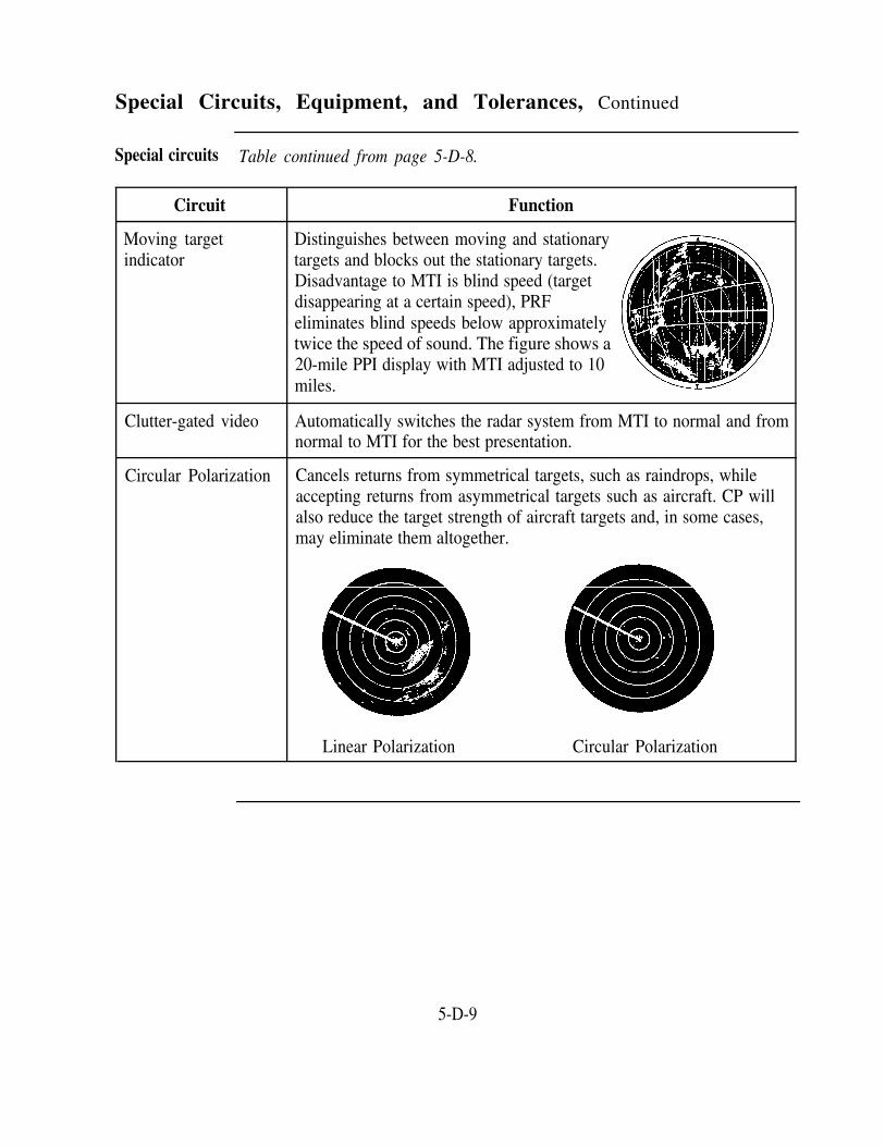
Special Circuits, Equipment, and Tolerances, Continued
Special circuits Table continued from page 5-D-8.
Circuit Function
Moving target Distinguishes between moving and stationaryindicator targets and blocks out the stationary targets.
Disadvantage to MTI is blind speed (targetdisappearing at a certain speed), PRFeliminates blind speeds below approximatelytwice the speed of sound. The figure shows a20-mile PPI display with MTI adjusted to 10miles.
Clutter-gated video Automatically switches the radar system from MTI to normal and fromnormal to MTI for the best presentation.
Circular Polarization Cancels returns from symmetrical targets, such as raindrops, whileaccepting returns from asymmetrical targets such as aircraft. CP willalso reduce the target strength of aircraft targets and, in some cases,may eliminate them altogether.
Linear Polarization Circular Polarization
5-D-9

Radar Mapping Systems
Introduction
Map overlay
Map overlaydrawbacks
A radar controller uses the range marks on the PPI and the compass rosearound the edge of the scope to obtain the position of an aircraft target.Information from these two sources only gives range and azimuth from theradar antenna. It does not depict the geographical location of the aircraft;therefore, some type of map display would be helpful. Two types ofmapping are available as integral parts of a PPI--a map overlay and videomapping.
The simplest form of mapping system is the map overlay. As the nameimplies, it is installed so that it covers the face of the CRT. The overlay ismade of transparent plastic. It has etched into the surface necessaryreference marks as well as the location of NAVAIDs, runways, andobstructions. The overlay is edge-lighted, and you can control the brilliance.
There are two built-in disadvantages to the map overlay. Since the map isinstalled a short distance away from the tube, the targets do not appear inproper relation to the map unless you look at the target from a point directlyabove the target. When your viewing position changes, targets apparently driftaway from one of the etched courses. This causes an error called parallax.You must be extremely careful of your posture so that you can observe thetarget correctly and prevent parallax. The other disadvantage is that the map isonly good for one range setting of the radarscope since it does not expand withthe display on the tube.
Video mapping The video map is a great improvement over the map overlay. The video map isproduced by a separate mapping unit. A scale map with the desired features isdrawn and then reproduced as a round photographic negative. This informationis fed to the video amplifier and then mixed with radar information from thereceiver so that the resulting signals to the PPI contain a combination of radarand map data. The antenna scan and the map scan are synchronized so the mapis developed directly on the PPI as the sweep progresses. The result, andbiggest advantage of the video map, is that the map expands or contracts as therange of the indicator is changed. The map coverage is in direct proportion tothe area covered and is accurate when the scope is off-centered.
Continued on next page
5-D-10

Radar Mapping Systems, Continued
Video Mapping Since the map is produced on the face of the tube along with the radar(continued) information, there is no parallax error. Thus, with a single map and mapping
unit, a number of ranges with corresponding plotting information areavailable for display on several indicators operating independently of eachother.
Video mapdrawbacks
The video map is subject to some drift. Slight errors resulting from drift canusually be corrected by a radar technician. Another disadvantage of thevideo map is the possibility of failure of the mapping unit, which results inno map on the PPI. You should refer to Air Traffic Control, FAA Order7110.65, for procedures to be followed when radar mapping is not available.
5-D-11

Air Traffic Control Radar Beacon System
Introduction Secondary surveillance radar is the term used for the ATC radar beaconsystem. This is in contrast to primary radar that was described during theearlier discussion of the echo principal. Secondary surveillance radar is aseparate system and is capable of independent operation. In normal ATCuse, secondary surveillance radar is slaved with ASR. A display of both theprimary and secondary radar targets is presented on the associated PPI.
Functions The functions of the ATC radar beacon are as follows:
Reinforcement of radar targetRapid target identificationExtension of radar coverage area (up to 200 miles)Transmission of altitude and other data
Components The components of the secondary surveillance radar are as follows:
Interrogator on the groundTransponder in an aircraftDisplay on an ATC radarscope
Continued on next page
5-D-12

Air Traffic Control Radar Beacon System, Continued
Components(continued)
When the word radar is used, it refers to a primary radar system. Primaryradar differs from secondary surveillance radar in that primary radar displaysreflected signals and does not display signals that have been transmitted by anairborne transponder. The two systems work together and are displayed onthe scope at the same time.
Secondarysurveillanceradaradvantages
Secondary surveillance radar effectively counteracts the followingshortcomings of primary radar:
The limiting effect of aircraft reflection areas that vary -with aircraftsize and configurationDisplays degraded by weather conditions, especially precipitationImpairment of the radar display by ground clutter even though theradar is equipped with MTIBlind spots in the antenna coverage pattern
Continued on next page
5-D-13

Air Traffic Control Radar Beacon System, Continued
IFF/SIF Identification Friend or Foe (IFF) electronically distinguishes betweenfriendly and hostile aircraft. Selective Identification Feature (SIF) is a formof IFF that enables the IFF system to generate many variably coded replies.
Interrogator set The Interrogator Set consists of a beacon-type IFF/SIF system and processingunits that provide synthetic video for display on the radar PPI. It enhancesthe radar operator's PPI display by replacing the conventional IFF responsefrom the aircraft with a target symbol that represents a variety of aircraftstatus conditions and with two sets of numbers that provide directidentification and altitude.
The targets are continuously refreshed to prevent target fade and to providethe operator with easy-to-read information. Target trail dots are available toportray course history and/or to provide an indication of ground speed. Theoperator selects the information display that he or she needs on the PPI. Anaircraft emergency, hijack, or communications failure is automaticallydisplayed in addition to the information displays that the operator selects.
Applicationmodes
The IFF/SIF system is known as ATCRBS. The ATCRBS is capable ofmaking interrogations in any four of the six different modes shown in thetable below. Mode A is the civil and military air traffic control mode. Sincecivil mode A is the same as mode 3 in military equipment, this common airtraffic control mode is called mode 3/A. Modes 1 and 2 are military tacticalmodes. Mode B is a civil air traffic control mode, but is not used in theUnited States. Mode C is used for automatic altitude transmissions. Mode Dhas been established, but its use has not been specified.
Mode Application Mode Application
1 Military IFF B Civil (ATC)
2 Military IFF C Civil (Altitude)
3/A Common (ATC) D Civil (unassigned)
Continued on next page
5-D-14

Air Traffic Control Radar Beacon System, Continued
Direct altitude Besides receiving altitude information from transponder-equipped aircraft, theand identity DAIR equipment presents digitally derived synthetic display markers andreadout system numerical data blocks. These blocks do not fade from the scope as do
primary radar targets. This data block displayed adjacent to the center mark(aircraft’s actual position) consists of the assigned beacon code that theaircraft is squawking and the altitude at which the aircraft is flying. Altitudeis indicated in 100-foot increments from MSL.
Altitude data is received through mode C interrogations to aircrafttransponders. Interrogations can be filtered to display only aircraft targetswithin controller-selected altitude levels.
Traffic alert TCAS is an airborne collision avoidance system based on radar beaconand collision signals that operates independent of ground-based equipment. Currently, twoavoidance versions exist:system (TCAS)
TCAS I—provides proximity warnings only to assist the pilot in the visualacquisition of conflicting aircraft. No recommended avoidance maneuversare provided.TCAS II—provides traffic advisories and resolution advisories.Resolution advisories provide recommended maneuvers in a verticaldirection (climb or descend only) to avoid conflicting traffic.
5-D-15

Radars
Introduction In this section, we briefly describe radar equipment in general use. Thisinformation is not all-inclusive or a substitute for familiarity with theequipment in use at your facility. For more detailed information on thecapabilities and operating controls of these systems, study the operator’ssection of the applicable technical manual.
GPN-27 radar The ASR-8 is a solid-state, airport surveillance radar system. It is used to(ASR-8) detect primary radar aircraft targets within 60 miles of the antenna site. The
system is reliable and easy to service. Except for the antenna, majorassemblies are duplicated to provide dual-channel operation. If one channelfails, the operator can switch to the standby channel.
The ASR-8 is interfaced with the TPX-42 system. Also, the ASR-8 uses astaggered PRF to prevent the occurrence of blind speeds caused by MTI.
The ASR approach course line must coincide as nearly as feasible with therunway centerline extended. Maximum error left or right of the runwayedges must not exceed 500 feet at a point 1 mile from the approach end of therunway.
FPN-63 radar The FPN-63 PAR is a solid-state unit and can be mounted on a remotelycontrolled turntable. The coverage of the FPN-63 is 8 degrees in elevationand 20 degrees in azimuth. It allows either a 10- or 20-mile range selection.When MTI is used, the RANGE SELECT switch will choose either 10 or 15miles. The 5-mile range marks on the AZ-EL scope are brighter than theothers. There is also a PAR minimums marker on the elevation scan thatmarks the decision height (DH) for the runway in use.
Continued on next page
5-D-16

Radars, Continued
FPN-63 radar The FPN-63 has a staggered PRF and an MTI velocity offset control. Whenechoes of bad weather or blocks of trees show on the scope, you may varythe MTI control to block their echoes.
On a PAR approach, the course deviation must not exceed 30 feet or 0.2degree, whichever is greater, at the runway threshold. The rangeinformation given must be accurate within plus or minus 2 percent. Also, thePAR radar must be capable of detecting an aircraft on the runway centerlineextended at an altitude of 2,000 feet and distance equal to the maximumrange of the scope.
FACSFAC air The FACTS is the basic system used to provide air traffic control of the Navy'scontrol operating areas (OPAREAS). FACTS is an automated control system whichtracking system consists of computers, displays, computer programs, peripherals, and internal(FYK-17) and external interfaces with associated systems.
FACTS provides a multicolor display. Each of the four colors (red, orange,yellow, and green) displays eight levels of intensity. These color differencesenable the controller to delineate such things as weather, targets, aircraft, "hotareas," and other map data by vivid color.
The FACTS system accepts data from remote long-range and short-rangesurveillance radars. FACTS then processes and displays the radar data invarious combinations of letters, numbers, symbols, and colors. The FACTSsystem also interfaces with the FAA National Airspace System Enroute StageA, ARTS facilities, and the Advanced Combat Direction System (ACDS).
5-D-17

Radar Performance Characteristics
Introduction When a radar system is developed that detects only flying aircraft and nothingelse, the radar controller will have a nearly perfect system for controllingtraffic. However, since the perfect radar system has yet to be developed, youneed to be aware of the limitations of existing systems. Such limitationsinclude target fades, anomalous propagation, false targets, jamming, andelectronic interference.
Target fades A property of all radar systems with which the controller should becomethoroughly familiar is target fading. Target fades varies with the type ofequipment, antenna height, tilt angle of the antenna, atmospheric conditions,and the surrounding terrain. Target fades are clear when an aircraft is over theantenna site. The degree and length of such a fade is determined by the amountof antenna tilt. The lower the tilt angle of the antenna, the better the low-anglecoverage. Conversely, the higher the tilt angle of the antenna, the better thehigh-angle coverage. Most antennas are set to give maximum coverage for theparticular type of control being employed.
The coverage in range, altitude, and azimuth for a particular site is determinedby means of a flight inspection evaluation. An FAA flight inspection teamconducts this evaluation before a facility is commissioned. When a previouslyunknown fade area is suspected, another flight inspection should be requestedto verify or confirm its existence. The data obtained from the flight inspectiongives the controller an indication of coverage and target fades built in the typeof equipment being used. To understand the capabilities and limitations of thesystem, you should become thoroughly familiar with the coverage pattern andfade areas determined by the flight inspection. For further information and adetailed description of the procedures used when flight inspections areperformed, refer to the United States Standard Flight Inspection Manual,NAVAIR 16-1-520, and NATOPS Air Traffic Control Facilities Manual,NAVAIR 00-80T-114.
Continued on next page
5-D-18

Radar Performance Characteristics, Continued
Anomalouspropagation
The atmosphere surrounding earth is not uniform in density or moisturecontent. It is possible for local conditions to exist in which radar beams arebent upon passage through the atmosphere. Conditions under which theradar beam does not travel a straight line are called conditions of anomalouspropagation. This condition is most apt to occur on days when there is littlewind and when the air temperature is different from the ground temperature.
Anomalous propagation is most common over water where water evaporationcauses a temperature and moisture gradient to exist. The refraction of dry ordense air is greater than that of moist or less dense air; therefore, radarbeams are bent in the direction of the dry or dense layers. The figure depictstwo conditions of anomalous propagation—the atmosphere causing adownward bending of radar beams and the atmosphere causing an upwardbending of radar beams.
Because of anomalous propagation, targets hundreds of miles away may bedetected even though they are far below the horizon. Conversely, relativelyclose targets may not be detected.
False targets A proficient radar controller is quick to recognize a temperature inversion asa false target. Such indications are often secondary reflections of radarenergy from isolated refracting areas in a temperature inversion level.Correlation of radar reports with the National Weather Service recordsindicates that a temperature inversion is usually present when unidentifiedflying objects appear on the scope. These inversions often travel across theradar at tremendous speeds and in changing directions. Apparently thisphenomenon is produced by isolated refracting areas traveling with the wind
Continued on next page
5-D-19

Radar Performance Characteristics, Continued
False targets(continued)
Radar jamming
Electronicradarinterference
at or near temperature inversion levels. The exact size, shape, andcomposition of these isolated areas is not known. It is believed that they maybe atmospheric eddies produced by a shearing action of dissimilar air strata.It appears that such eddies may reflect and focus the radar energy with a lenseffect. This produces a small concentration of ground return with sufficientstrength to show up on the radar display.
Jamming, as used in conjunction with radar, is defined as an introduction offalse radiation into radar and radar devices. False targets produced byjamming may appear on the scope at varying ranges and bearings. In somecases, they may clutter large portions of the scope.
Jamming is classified as two main categories--active and passive. Activejammers are those which generate radar energy, producing interference.Passive jammers are those that act as parasitic radiators, such as chaff. Chaffis thin strips of aluminum or other metal cut to a particular length. Whenreleased from aircraft at high altitudes, the strips float down to the groundslowly. The resultant echoes cause large areas of clutter.
Controlled jamming is conducted by the military and regulated by the FAA topreclude interference with air traffic control radar. When prior notificationhas not been received, controllers observing jamming operations shouldnotify the appropriate authority. Procedures are described in Air TrafficControl, FAA Order 7110.65.
Interference from other radar installations that operate on a similar frequencymay be encountered when two or more radar installations are in closeproximity. When this interference is encountered, nearby radar installationsshould be advised to check the frequency calibration of their equipment.
Most radar installations have dual channels so that a standby channel isalways available. At times, the standby channel transmits a signal thatproduces interference. In most cases, fine tuning of the equipment by thetechnician decreases the amount of interference.
5-D-20

Section EShipboard Equipment
Overview
Introduction The equipment that you will use to perform your duties in CCA is, in somecases, very different from what you find at a shore facility. Training in CCAon an operator’s position includes equipment operation and control procedures.As we discussed in previous sections, your equipment is essential to your job.Providing safe control depends on your knowing how to operate the equipmentand to monitor it to make sure it operates correctly.
In this section This section covers the following topics:
Search Radar
Topic See Page
5-E-2
Precision Approach and Landing System 5-E-3
Optical Landing Systems 5-E-7
ILARTS 5-E-9
5-E-1

Search Radar
Introduction Most aircraft carriers have a variety of air-search radars on board.
Search radars Some air-search radars are long-range (up to 240 miles); others are medium-range (50 to 60 miles). Sometimes, CDC and CCA share the use of shipboardradars; CDC for air tracking, air intercept, and surface tracking; and CCA forair traffic control.
Shipboard air search radars have IFF/SIF radar beacon systems that provide thesame capabilities as the ATCRBS/DAIR equipment used ashore. Thisequipment is referred to as CATCC/DAIR.
The obvious difference between radars used on board ships and radars usedashore is that shipboard radars are on a continuously moving airfield. For thisreason, most shipboard radars are gyroscopically and/or computably stabilized.These features allow the presentation you see on the radar repeater to remainorientated (magnetic north at the top of the scope) even though the ship is in aturn. There is also a ship heading marker/cursor displayed on the radarscopethat changes automatically as the ship changes course.
The radar repeaters used on board ship have the same features as those usedashore; that is, variable range control, off-center sweep and cursor, and rangemarks.
5-E-2

Precision Approach and Landing System
Introduction PALS (formerly called the Automatic Carrier Landing System) includes theAN/SPN-46 and associated systems that enable pilots to perform precisioninstrument approaches to the aircraft carrier. To provide continuous capabilityto the pilot and controllers, the PALS has a precision tracking radar that iscoupled to a computer data link.
PALS modes of PALS has three general types of control. They differ on the basis of type ofoperation control (automatic or manual) and source of information (display or voice).
Fully automatic approach (Mode I/IA)Manual controlled approach with PALS glide slope and lineupinformation provided by pilot cockpit display (Mode II/IIT)Conventional manual CCA in which the controller provides glide slope,azimuth, and range information by voice (Mode III)
AN/SPN-46 The AN/SPN-46 has two consoles each of which can track (lock on) twoaircraft at a time. The SPN-46 also interfaces with the CATCC DAIR. Withthis interface, it is used to select the display of aircraft being tracked by theCATCC DAIR. This interface causes aircraft symbols and side numbers ofDAIR-tracked aircraft to appear on the console display.
Automaticlanding system
Besides providing precision tracking radar, the AN/SPN-46 has the capabilityof providing a completely automatic landing. When an aircraft approaches acarrier, the precision tracking radar monitors the aircraft's progress and feedsthe position information to a computer. The computer measures the aircraft'sposition in relation to a preselected approach path. To maneuver the aircraft tothe desired path, the computer determines what corrections are necessary. Thecorrections are then transmitted by radio to the aircraft. Equipment in theaircraft feeds the commands, through an autopilot, to the aircraft's controlsurfaces and throttle, and the aircraft reacts accordingly. The same correctionsare also fed to the CCA operator's console, including information concerningthe distance from the ship to the aircraft.
Continued on next page
5-E-3

Precision Approach and Landing System, Continued
SPN-41 ICLS The SPN-41 system is a completely independent guidance/navigation systemthat, besides providing a means for monitoring, affords the pilot anothermethod of making an instrument approach to the ship. In this system,shipboard transmitters scan coded microwave signals aligned on the desiredapproach path. On the aircraft's instrument panel, the information from thissystem is displayed on an ILS-type cross-pointer needles display. A pilot canreceive SPN-41 guidance information in excess of 20 miles from a ship. Thistype of approach requires the pilot to transfer to a visual landing aid such asthe fresnel lens system prior to touchdown.
Continued on next page
5-E-4

Precision Approach and Landing System, Continued
SPN-41 usage The pilot needs to monitor his or her progress during a manual or fullyautomatic approach. The SPN-41 allows the pilot to monitor and crosscheckthe SPN-46 performance.
The SPN-41 has capabilities that allow it to serve the following functions:
ARA-63
Capabilities SPN-41 serves as...
Extended range A feeder system for the SPN-46
Independent guidanceand navigation system
An independent landing monitor (ILM) to allowthe pilot to monitor and crosscheck SPN-46performance during a manual or fully automaticapproach
A backup when the SPN-46 equipment fails thatallows the pilot to continue a precision approach
The ARA-63 receiver/decoder is used in the aircraft in conjunction with theSPN-41 system. It is used by the pilot to obtain carrier line-up prior to enteringthe SPN-46 acquisition gate. The ARA-63 is also used to monitor SPN-46automatic precision approach performance in the aircraft.
Ancillaryequipment
The ancillary equipment that is normally located in the CCA control roomincludes the following:
Communications consoles—models of equipment vary but theirfunction is equivalent to communications consoles used at shorestationsGyro repeater—indicates the ship's true courseDeck condition lights—indicate ready or fouled deckSPN-44 radar—indicates the airspeed of aircraft on finalapproach, either true or closing, as selected by CCA or the LSO
Continued on next gage
5-E-5

Precision Approach and Landing System, Continued
Ancillaryequipment(continued)
Integrated Launch and Recovery Television System(ILARTS) and CCTV displays—used to monitor and recordaircraft landingsVertical edge-lighted status board—used to record and displayaircraft missions, fuel states, profiles, etc.
IntegratedShipboardInformationSystem
A new system scheduled for installation on board CVNs is the IntegratedShipboard Information System (ISIS). This system is designed to replaceedge-lighted status boards and automate data entry and display of flightoperations information.
5-E-6

Optical Landing Systems
Introduction Besides CCA equipment, there are optical systems on board a carrier that aidpilots in landing aboard the carrier.
Fresnel lens The purpose of the FLOLS is to provide the pilot with a visual indication ofoptical landing his or her relative position with respect to a prescribed glide slope. Thissystem glide slope, as determined by the lens settings, is designed to bring the
aircraft down to the deck within the cross-deck pendant area with a safeclearance above the stern ramp of the carrier.
A yellow bar of light is displayed over the full width of the lens box. Thelens box may be considered a window through which the pilot views the barof light. The bar of light appears as though it were located approximately150 feet beyond the window. When viewed from anywhere on the prescribedglide slope, this bar of light (ball) appears in line with the green datum lights.The ball rises above the datum lights as the pilot rises above the glide slope,and eventually slides off the top of the lens box when the pilot is more than3/4 degree above the glide slope. The same holds true as the pilot dropsbelow the datum lights and the ball finally slides off the bottom of the lensbox.
At great distances from the lens unit, it is difficult to distinguish the relativeposition of the ball with respect to the datum lights. The reason is the ballcan be distinguished before the green datum lights become visible. Pilots aretherefore provided with a warning of low ball by installing a RED lens in thebottom cell of the lens box. Thus, regardless of distance, when the ball isRED instead of YELLOW, a pilot will know when he or she is too low ortoo high.
Continued on next page
5-E-7

Optical Landing Systems, Continued
Manually MOVLAS is an emergency system that is intended to be used when theoperated, visual primary optical landing system is rendered inoperative. The system presentslanding aidsystem
glide slope information to the pilot of an approaching aircraft in the samevisual form presented by the FLOLS. As a substitute for FLOLS, theMOVLAS has three modes of operation.
Mode I has a light box installed directly in front of the FLOLSlens. It acts as a substitute for the normal ball presentation, butit still uses the datum, waveoff, and cut lights of FLOLS.Mode II is completely independent of the FLOLS. It is locatedbetween 75 and 100 feet aft of the inoperable system. Besidesthe ball presentation, it consists of reference datum, waveoff,and cut lights.Mode III installation is similar to Mode II but is located on thestarboard (right) side of the flight deck aft of the islandstructure.
5-E-8

ILARTS
Introduction
ILARTScomponents
Centerlinecamera
Island camera
The Integrated Launch and Recovery Television Surveillance System(ILARTS) (formerly PLAT) records aircraft launches and recoveries.Through remote cameras and monitors, ILARTS provides an instant pictureof all launches and landings plus the capability of tape recordings for futurereplays.
ILARTS in concert with the ship's closed-circuit television (CCTV) consistsof four to six cameras, monitors, control synchronization, a video taperecorder, and associated power and distribution systems.
The centerline camera pickup station is unmanned and consists of two units(primary and backup) that provide instantaneous (real-time) monitoring ofaircraft landings. The point-in-space (window) viewed by the centerlinecameras is stabilized to compensate for the pitch and roll of the ship. TheFLOLS is gyroscopically stabilized to maintain a constant reference to earth'shorizon regardless of the pitch and roll due to sea state, ship maneuvers, andso forth. Both centerline cameras are stabilized from the same source as theFLOLS. Within the limits of its corrective ability, this stabilizationcompensates for the camera motion so that the camera's field remains ontarget regardless of the ship’s pitch and roll. From their centerline position,these cameras follow the aircraft from approach to touchdown.
The island camera is mounted on the superstructure and is manned by anoperator. The operator uses this camera to monitor aircraft side numbers inaddition to recording launches, general flight deck activities, and accidents.During landings, the island camera takes over coverage at touchdown andprovides final coverage of the landing.
Continued on next page
5-E-9

ILARTS, Continued
Monitors Monitoring units are located in various compartments such as the pilots'ready rooms, CCA, captain's bridge, and the LSO's platform. In thismanner, distribution of the "topside activity" provides a convenientobservation media for the general situation on the flight deck. Anotherfeature is the availability of the transmitted data to widely dispersed locationsand personnel. This feature contributes to a coordinated team effortthroughout the ship. All data are simultaneously recorded; the tapes maythen be stored for later use as debriefing material and as training aids.
5-E-10

CHAPTER 6
OverviewAIRSPACE CLASSIFICATION
Introduction The FAA is responsible for the safe and efficient use of airspace in the UnitedStates. Since this airspace includes areas where military aircraft operationstake place, Navy air traffic controllers must comply with FAA air traffic rulesand regulations.
There are two categories of airspace or airspace areas: regulatory andnonregulatory. Regulatory airspace is designated, altered, or revoked by rule,regulation, or order. Within these two categories, there are four types:controlled, uncontrolled, special use, and other airspace. The categories andtypes of airspace are dictated by the complexity or density of aircraftmovements, the nature of operations conducted within the airspace, the level ofsafety required, and the national and public interest.
This chapter introduces you to those operational requirements and termsassociated with these areas of airspace and is compiled from informationcontained in the FARs, AIM, and Procedures for Handling Airspace Matters,FAA Order 7400.2.
Objective The material in this chapter will enable you to:
Recognize the types of airspace.Identify the purpose of airways.Identify the purpose of jet routes.State how airspace is charted.Identify rules and restrictions associated with each type of airspace.
Continued on next page
6-1

Overview, Continued
Acronyms The following table contains a list of acronyms that you must knowunderstand the material in this chanter:
to
Acronym Meaning
AGL Above ground level
AIM Aeronautical Information Manual
ATC Air traffic control
DoD
FAA
Department of Defense
Federal Aviation Administration
FACSFAC Fleet area control and surveillance facility
FAR
ft
Federal aviation regulation
feet
FL Flight level
IFR Instrument flight rules
L/MF Low/medium frequency
mi mile
MOA
MSL
Military operations area
Mean sea level
MTR Military training route
NA
nm
Not applicable
Nautical mile
VFR Visual flight rules
VOR VHF omni-directional range
VORTAC VHF omni-directional range/tactical air navigation
Continued on next page
6-2

Overview, Continued
Topics This chapter is divided into four sections:
Section Topic See Page
A Controlled Airspace 6-A-1
B Uncontrolled Airspace 6-B-1
C Special Use Airspace 6-C-1
D Other Airspace 6-D-1
6-3


Section AControlled Airspace
Overview
Introduction As an air traffic controller, you will need to become familiar with controlledairspace, its restrictions and limitations, and the dimensions associated withthe different classifications of airspace.
In this section This section covers the following topics:
Topic See Page
VOR and L/MF Airways System and Jet Route System 6-A-2
Controlled Airspace 6-A-3
6-A-1

VOR and L/MF Airways System and Jet Route System
Introduction
VOR andL/MF airways
Jet routes
Two route systems have been established for air navigational purposes withinthe National Airspace System (NAS)—the VOR and L/MF airways systemand the jet-route system. These systems can be viewed as highways in thesky. They are designated routes and are depicted on aeronautical charts.Refer to the FARs, AIM, and FAA Order 7400.2 for more detailed information.
The VOR and L/MF airways system consists of airways designated from1,200 feet above the surface up to but not including 18,000 MSL. To theextent possible, VOR and L/MF airways align in an overlying manner to easethe transition between each.
VOR airways are depicted in blue on aeronautical charts and are identified bya V (spoken: Victor) followed by an airway number (e.g., V11). L/MFairways are identified by color name and number (e.g., Green One). Greenand red L/MF airways are plotted east and west. Blue and amber L/MFairways are plotted north and south.
Except in Alaska, VOR airways are established solely on VOR or VORTACnavigation facilities.
The jet route system consists of routes established from 18,000 feet MSL(FL180) to 45,000 feet MSL (FL450) inclusive.
They are depicted on aeronautical charts and identified by a J (spoken: Jay)for jet route followed by the airway number (e.g., J14).
Except in Alaska, jet routes are established solely on VOR or VORTACnavigation facilities.
6-A-2
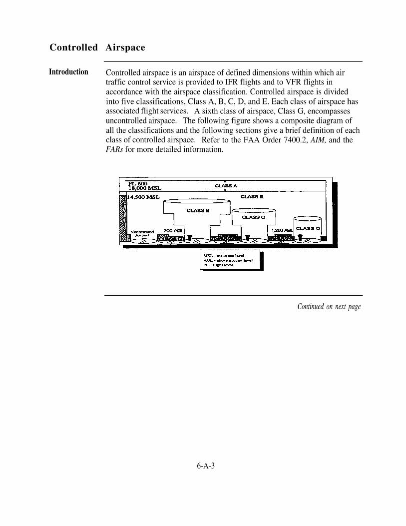
Controlled Airspace
Introduction Controlled airspace is an airspace of defined dimensions within which airtraffic control service is provided to IFR flights and to VFR flights inaccordance with the airspace classification. Controlled airspace is dividedinto five classifications, Class A, B, C, D, and E. Each class of airspace hasassociated flight services. A sixth class of airspace, Class G, encompassesuncontrolled airspace. The following figure shows a composite diagram ofall the classifications and the following sections give a brief definition of eachclass of controlled airspace. Refer to the FAA Order 7400.2, AIM, and theFARs for more detailed information.
Continued on next page
6-A-3

Controlled Airspace, Continued
Airspace limits, The table below outlines some of the limits, rules, and restrictions associatedrules, and with each class of controlled airspace.restrictions
AirspaceClass
A
Configuration
NA
Height Limits VFR Weather Minimums
Flight Distance fromVisibility Clouds
18,000 ft MSL up NA NAto and includingFL600— positivecontrol of aircraftand IFR apply
B
C
Individually tailored Surface to 10,000 3 statute mi Clear of cloudsconsisting of a ft MSLsurface area and two surrounding theor more additional busiest U.S.areas airports
Individually tailored Surface to 4,000 3 statute mi 500 ft belowusually consisting of ft above the 1,000 ft abovea 5 nm radius core airport elevation— 2,000 ft horizontalsurface area, an core area isouter circle with a surface to 4,000;10 nm radius, and an outer circle area isouter area which is 1,200 ft to 4,000normally 20 nm ft; outer area to
the ceiling of theapproach control'sdelegated airspace
Continued on next page
6-A-4

Controlled Airspace, Continued
Airspace limits, Table continued from page 6-A-4.rules, andrestrictions
Airspace Configuration Height Limits VFR Weather MinimumsClass
Flight Distance fromVisibility Clouds
D Individually tailored Surface to 3 statute mi 500 ft belowand includes published 2,500 ft above 1,000 ft aboveinstrument procedures the airport 2,000 ft horizontal
elevation
E Airspace not Except for a Less thandesignated as Class A, upper vertical 10,000 ftB, C, D, or G limit of MSL—3 statute 500 ft below
18,000 ft, no mi 1,000 ft abovedefined 2,000 ft horizontalvertical limit—extendsupward from At or aboveeither the 10,000 ftsurface or a MSL—5 1,000 ft belowdesignated statute mi 1,000 ft abovealtitude to the 1 statute mioverlying or horizontaladjacentcontrolledairspace
Wherecontrolledairspace ischarted
Class A airspace is not specifically charted. Class B, C, D, and E airspace ischarted on:
Sectional chartsIFR enroute low-altitude chartsTerminal area charts
6-A-5


Section BUncontrolled Airspace
Overview
Introduction Class G airspace encompasses all airspace not considered A, B, C, D, and Eand is classified as uncontrolled.
In this section This section covers the following topic:
Topic See Page
Uncontrolled Airspace 6-B-2
6-B-1

Uncontrolled Airspace
Introduction Airspace that is not controlled is classified as Class G airspace.
RegulationsconcerningClass Gairspace
The table below defines the limits, rules, and restrictions associated withuncontrolled airspace.
Airspace Configuration Height Limits VFR Weather MinimumsClass
Flight Distance fromVisibility Clouds
G Airspace not Uncontrolled 1,200 ft or lessdesignated as Class A, above theB, C, D, or E surface
(regardless ofMSLaltitude)—Day—1 statute Clear of cloudsmiNight—3 500 ft belowstatute mi 1,000 ft above
2,000 ft horizontalMore than1,200 ft abovethe surface butless than10,000 ftMSL—Day—1 statute 500 ft belowmi 1,000 ft above
2,000 ft horizontal
Night—3 500 ft belowstatute mi 1,000 ft above
2,000 ft horizontal
Continued on next page
6-B-2

Uncontrolled Airspace, Continued
RegulationsconcerningClass Gairspace
Table continued from page 6-B-2 l
AirspaceClass
G
Configuration Height Limits VFR Weather Minimums
Flight Distance fromVisibility Clouds
More than1,200 ft abovethe surfaceand at orabove 10,000 ftMSL—5 1,000 ft belowstatute mi 1,000 ft above
1 statute mihorizontal
6-B-3


Overview
Introduction Special use airspace is airspace in which the:
In this section
Section CSpecial Use Airspace
activities in the area must be confined because of their very nature, orlimitations must be imposed upon aircraft operations that are not partof the activities taking place in this area.
The vertical and horizontal limits of special use airspace areas and theirperiods of operation are defined.
Except for controlled firing areas, the areas and their periods of operation aredepicted on aeronautical charts.
This section covers the following topics:
Topic
Prohibited and Restricted Areas
Warning and Alert Areas
Military Operations Areas
Controlled Firing Areas
See Page
6-C-2
6-C-3
6-C-4
6-C-5
6-C-1

Prohibited and Restricted Areas
Introduction As an air traffic controller, you must be familiar with any prohibited orrestricted airspace that is in your area of responsibility.
Prohibitedareas
Prohibited areas are established in FAR, Part 73, and thus are consideredregulatory airspace. Prohibited areas are published in Special Use Airspace,FAA Order 7400.8, and FLIP AP/1A and are depicted on aeronauticalcharts.
Prohibited areas contain airspace of defined dimensions within which theflight of aircraft is prohibited. Such areas are established for security reasonsor other reasons associated with the national welfare, for example, airspaceover the White House.
Prohibited areas are identified by the prefix letter "P" followed by a dash, atwo-digit number, and a location (city or town or military reservation), forexample, "P-56 District of Columbia."
Restricted Restricted areas are established in FAR, Part 73, and thus are consideredareas regulatory airspace. Restricted areas are published in FAA Order 7400.8 and
FLIP AP/1A and are depicted on aeronautical charts.
Restricted areas contain airspace identified by an area on the surface withinwhich the flight of aircraft, while not wholly prohibited, is subject torestrictions. Such areas are established for artillery firing, aerial gunnery, orguided missiles.
Restricted areas are depicted on the enroute charts for use at the altitude orflight level being flown. For joint-use restricted areas, the name of thecontrolling agency is shown on the charts. Unless otherwise requested by theusing agency, the phrase "NO A/G" is shown on the charts for all prohibitedareas and nonjoint-use restricted areas. This phrase indicates that voicecommunications are not maintained with aircraft operating in these areas.
Restricted areas are identified by the prefix letter "R" followed by a dash, afour-digit number, and a location (city or town or military reservation andstate), for example, "R-4813 Carson Sink, NV." A letter suffix is assignedto denote subdivisions, for example, "R-4803N Fallon, NV."
6-C-2

Warning and Alert Areas
Introduction Warning and Alert Areas provide airspace for pilots to practice varioustactical maneuvers. To provide necessary ATC services, you must know thelocation of any warning or alert areas in your area of control jurisdiction andthe type of aircraft operations conducted in these areas.
Warning areas A warning area is airspace that contains hazards to nonparticipating aircraft.Warning areas are developed with defined dimensions extending from 3 milesoutward from a coastline. Warning areas may be located over domestic orinternational waters.
Fleet operating areas off the East, West, and Gulf coasts of the United Statesconsist primarily of warning areas under the jurisdiction of a U.S. NavyFACSFAC.
Warning areas are identified by the prefix letter "W" followed by a dash, atwo- or three-digit number, and a location (city or town or area or militaryreservation and state), for example, "W-72 Vacapes, VA." A letter suffix isassigned to denote subdivisions, for example, "W-72A Vacapes, VA."Warning areas are nonregulatory airspace. Warning areas are published inFAA Order 7400.8 and FLIP AP/1A and are depicted on aeronautical charts.
Alert areas Alert areas are designated to inform nonparticipating pilots of areas that maycontain a high volume of pilot training or an unusual type of aerial activity.These are areas in which pilots should be particularly alert. All activitywithin an alert area must be conducted according to FARs without waiver.Pilots of participating aircraft as well as pilots transiting the area are equallyresponsible for collision avoidance.
U.S. Navy alert areas exist around many outlying fields (OLFs) where pilottraining and field carrier landing practices take place.
Alert areas are identified by the prefix letter "A" followed by two or moredigits, for example, "A-680 Coupeville, WA." Alert areas are nonregulatoryairspace. They are published in FAA Order 7400.8 and FLIP AP/1A and aredepicted on aeronautical charts.
6-C-3

Military Operations Areas
Introduction MOAs consist of airspace defined by altitude and geographical location.
Military MOAs are established to separate certain military training activities from IFRoperations area air traffic. Whenever a MOA is being used, nonparticipating IFR traffic may
be cleared through a MOA if IFR separation can be provided by the ATCauthority. Otherwise, the control facility must reroute or restrict thenonparticipating aircraft.
Nonhazardous activities such as combat tactics, aerobatics, intercepts,instrument training, aerial refueling, and formation flight training take placein MOAs.
MOAs shall be identified by the use of a nickname from a geographicallocation or any other common name, for example, "Hunter" or "Gator", andif desired, further identified in numerical sequence, for example, "Gabbs 1")Gabbs 2", and so forth. Cardinal points, letters, or "high" and "low" maybe used to identify subsections, for example, "Mayport High." MOAs arenonregulatory airspace. They are published in FAA Order 7400.8 and aredepicted on sectional, terminal area, and IFR enroute low-altitude charts.
6-C-4

Controlled Firing Areas
Introduction Controlled firing areas contain activities which, if not conducted in acontrolled environment, could be hazardous to nonparticipating aircraft.
Controlledfiring areas
Controlled firing areas shall only be considered for those activities which areeither of short duration or of such a nature that they could be immediatelysuspended on notice that such activity might endanger nonparticipatingaircraft. Examples of such activities include field artillery, blasting,ordnance disposal, and chemical disposal.
The distinguishing feature of the controlled firing area, as compared to otherspecial use airspace, is that its activities are suspended immediately whenspotter aircraft, radar, or ground lookout positions indicate an aircraft mightbe approaching the area. Controlled firing areas are nonregulatory airspaceand are not charted because they do not cause a nonparticipating aircraft tochange its flight path.
6-C-5


Section DOther Airspace
Overview
Introduction Airspace that is not controlled, uncontrolled, or special use is categorized asother airspace.
In this section This section covers the following topics:
Topic See Page
Military Training Routes 6-D-2
Airport Advisory Areas 6-D-4
Parachute Jump Areas 6-D-5
6-D-1

Military Training Routes
Introduction To be proficient, the military services must train in a wide range of airbornetactics including "low level" combat tactics. The required maneuvers andhigh speeds are such that they may make the see-and-avoid aspect of VFRflight more difficult without increased vigilance. The MTR program is ajoint DoD and FAA venture to ensure the greatest practical level of safety forthese flight operations. Additional information concerning MTRs can befound in Special Military Operations, FAA Order 7610.4 and FLIP AP/1B.
Military Generally, MTRs are established below 10,000 feet MSL and for speeds intraining route excess of 250 knots. Routes are developed as follows:definition
Routes above 1,500 feet AGL are developed to be flown to the maximumextent possible under IFR conditions.Routes at 1,500 feet AGL and below are generally developed to be flownunder VFR conditions.Routes may be established for descent, climbout, and designatedmountainous terrain.
Published MTRs are published in sectional charts, IFR low-altitude enroute charts, andinformation FLIP Area Planning (AP/1B).
Routedesignation
Route designations are made as follows:
Military Training Route Designation
IFR MilitaryTraining Routes-IR
VFR MilitaryTraining Routes-VR
Operations on these routes are conducted byfollowing IFR regardless of weather conditions.
Operations on these routes are conducted byfollowing VFR. The flight visibility must be 5 milesor more, and the ceiling must be 3,000 feet AGL orgreater.
Continued on next page
6-D-2

Military Training Routes, Continued
Routeidentification
Routes are identified as follows:
Route Route Identification
IR and VR at or below 1,500 feet AGL (with A four-digit number suchno segment above 1,500 AGL) as IR1006 or VR1007
IR and VR above 1,500 feet AGL (segments A three-digit number suchof these routes may be below 1,500 AGL) as IR008 or VR009
Alternate IR and VR routes or route The basic or principle routesegments designation followed by a
letter suffix such asIR008A or VR1007B
6-D-3

Airport Advisory Areas
Introduction As a Navy air traffic controller providing approach control service, you mayhave a satellite airport within your area of jurisdiction which lies within anairport advisory area.
Airport An airport advisory area is the area within 10 statute miles of an airportadvisory area where a control tower is not operating but where a Flight Service Station
(FSS) is located. At such locations, the FSS provides advisory service toarriving and departing aircraft.
A local airport advisory program on the common traffic advisory frequency(CTAF) is established at those airports which lie within an airport advisoryarea. It is not mandatory that pilots participate, but it is stronglyrecommended they do.
6-D-4

Parachute Jump Areas
Introduction Parachute jump operations have the potential to disrupt the normal flow of airtraffic. Knowledge of jump areas will help ensure that you provide safe airtraffic service.
Parachutejump area
Parachute jump areas are established to identify airspace in which parachutejump operations are routinely conducted. These areas are identified by theuse of a nickname from a geographical location or any other common name,for example, "Coupeville OLF" or "Lewellen Drop Zone." Parachute jumpareas are described in terms of location (radial and DME fix or quadrant),vertical (altitude) extent, and specified period of time such as daily sunrise tosunset.
Parachute jump areas are published in FLIP AP/1A and Airport/FacilityDirectory booklets.
6-D-5


CHAPTER 7
OverviewFLIGHT ASSISTANCE SERVICES
Introduction As an Air Traffic Controller assigned to the flight planning branch of an airtraffic control facility, the assistance you provide to pilots is very important.Your assistance plays a critical role in the safety of the flight as well asproviding a smooth transition through the air traffic control system. You willneed a thorough understanding of the information presented in this chapter toperform as an Air Traffic Controller.
Objectives The material in this chapter will enable you to:
Describe the functions of the flight planning branch.Identify the assistance given to a pilot by the Air Traffic Controller(AC) in planning a flight.Identify the conditions that require search and rescue (SAR)operations, and state the procedures to be followed in effecting SARfor both instrument flight rules (IFR) and visual flight rules (VFR)flights.Identify individual and activity responsibilities for originating andexecuting procedures under the notice to airmen (NOTAM) system.
Acronyms The following table contains a list of acronyms that you must know tounderstand the material in this chanter.
Acronym Meaning
AC
AFSS
Air Traffic Controller
Automated flight service station
AIM Aeronautical Information Manual
AIRAD Airmen Advisory
ALNOT
ARTCC
ATC
Alert notice
Air route traffic control center
Air traffic control
Continued on next page
7-1

Overview, Continued
Acronyms Table continued from page 7-1.(continued)
Acronym Meaning
ATCFO Air Traffic Control Facility Officer
ATIS Automatic terminal information service
AWN Automated weather network
BASOPS Base Operations
CHUM
CNO
Chart updating manual
Chief of Naval Operations
DoD Department of Defense
DTG Date-Time Group
DVFR Defense Visual Flight Rules
ETA Estimated time of arrival
ETE Estimated time enroute
FAA
FAR
Federal Aviation Administration
Federal Aviation Regulations
FLIP DoD Flight Information Publication
FSS Flight Service Station
ICAO
ID
International Civil Aviation Organization
Identification
IFR Instrument Flight Rules
IMC Instrument Meteorological Conditions
INREQ
LABS
Information Request
Leased A/B system
NAVAID Navigational Aid
NOTAM Notice to Airmen
Continued on next page
7-2

Overview, Continued
Acronyms Table continued from page 7-2.(continued)
Topics
Acronym Meaning
PIREP Pilot weather report
QALQ Code asking if aircraft has landed or returned to station
RCC Rescue Coordination Center
SAR Search and Rescue
SID Standard instrument departure
SVFR Special visual flight rules
STAR Standard terminal arrival
TACAN UHF Omnidirectional Navigational Aid
VFR Visual Flight Rules
VIP Very Important Person
This chapter is divided into four sections:
Section Topic See Page
A Flight Planning Branch Functions 7-A-1
B Flight Planning 7-B-1
C Flight Handling 7-C-1
D NOTAMs 7-D-1
7-3


Overview
Section AFlight Planning Branch Functions
Introduction The function of the flight planning branch is to provide for planning, receiving,and processing flight plans as well as receiving and processing inbound flightinformation. The branch maintains a current inventory of aeronautical charts,publications, applicable directives, and NOTAM files. It also providesfacilities for the aircrew to conduct flight planning.
In this section This section covers the following topics:
Topic See Page
Flight Planning Branch Personnel 7-A-2
Duty Priority 7-A-3
Flight Planning Branch - Airfield Status Boards 7-A-4
Preflight Planning 7-A-5
7-A-1

Flight Planning Branch Personnel
Introduction Personnel assigned to the flight planning branch are responsible for matterspertaining to flight planning, flight plan processing, and flight guard.
Billets and Billets and responsibilities of the flight planning branch personnel areresponsibilities contained in the following table:
BilletDescription
FlightPlanningChief
Responsible Duties and ResponsibilitiesTo:
ATCFO Procuring and maintaining required publications,directives, charts, and suppliesMaintaining flight planning facilitiesMaintaining operational continuity between watchesQualifying personnelApprising ATCFO of equipment readinessProviding flight planning technical assistance to theATCFO
FlightPlanningSupervisor
Flight Dissemination of NOTAMsPlanning Chief Ensuring adequate supplies are available to the aircrewand Facility Assisting the aircrew in flight planning and flight planWatch filingSupervisor Supervising the processing and transmitting of flight plan:
and movement messages
Flight FlightPlanning PlanningDispatcher Supervisor
Receiving, processing, posting, and transmitting flightplans and movement messagesCoordinating with other facilities regarding flight plansand movement messagesHandling communications, aircraft flight guard, andinitiating overdue actionsMaintaining the NOTAM display
7-A-2

Duty Priority
Introduction Because there are many variables involved, it is impossible to provide a listof duty priorities that apply to every situation. Each set of circumstancesmust be evaluated on its own merit, and when more than one action isrequired, you must exercise your best judgement based on known facts andcircumstances. Action which appears most critical from a safety standpointshould be performed first.
Order ofpriorities
The following order of duty priorities is offered as a guideline:
Priority Situation Description
1 Emergency Life or property is in imminent danger.
2 Inflight Services Affecting aircraft in flight or otherwiseoperating on the airport service. Includesdelivery of ATC clearances, advisories, orrequests; issuance of military flightadvisory messages, NOTAMs, SARcommunications searches, flight planhandling, weather observations, PIREPs,and pilot briefings.
3 Preflight Services Directly affect aircraft operations butprovided prior to actual departure andusually by telephone. Includes pilotbriefings, recorded data, flight plan filingand processing, and aircraft operationalreservations.
7-A-3

Flight Planning Branch - Airfield Status Boards
Introduction Airfield status boards for flight operations personnel and flight data boardsfor the general public display airfield information.
Airfield status Airfield status boards provide general field information useful to pilots andboards flight planning personnel when they are planning a flight. The size, shape, and
construction are site unique. Items normally included in an airfield statusboard are as follows:
Current weather status (IFR or VFR)Runway in useRadio frequency usageField NAVAID statusField radar statusField arresting gear statusPertinent remarks (anything that might affect the flight)
7-A-4

Preflight Planning
Policy NATOPS General Flight and Operating Instructions, OPNAVINST 3710.7,states: "Before commencing a flight, the pilot in command shall be familiarwith all available information appropriate to the intended operation. Suchinformation should include but is not limited to available weather reports andforecasts, NOTAMs, fuel requirements, alternatives available if the flightcannot be completed as planned, and any anticipated delays."
Flight planning Much of a pilot's preflight planning is conducted in the flight planning branchbranch role of the facility. Although the overall responsibility for preflight planning rests
with the pilot in command, you, as an AC, share the responsibility. You mustensure that charts and publications are up-to-date and available for the pilotsuse, and you must also be aware of any recent changes that might affect thesafety of the flight.
The flight planning branch should have sufficient FLIPs, navigation equipment,and related information applicable to the mission of the facility. The followingtable lists the information that should be provided by the flight planningbranch:
Publication/Information Requirements
FLIPs Planning, area charts, enroute low altitude, enroute high altitude,(Sufficient quantity for enroute supplements, terminal low altitude, terminal high
mission) altitude, SIDs, STARS
NOTAM Shall be maintained up to date for ready reference anddisplayed according to DoD Notice to Airmen (NOTAM)System, OPNAVINST 3721.20
Publications that shall be FAR, Part 91; AIM; Contractions Manual; Locationmade available in limited Identifiers; NOTAM Publication; Foreign Clearance Guide;quantities for reference International Flight Information Manual; International
(where required) NOTAMs; Air Almanac; Catalog of Maps, Charts, andRelated Products (Part 1); Bulletin or Bulletin Digest;CHUM/CHUM Supplement.
Information that shall be A general flight planning chart, local area flight planning chartsprominently displayed of suitable scale showing VFR arrival and departure corridors, a
(appropriate to the mission scaled terrain/obstruction map to include overlays depictingof the air activity) current SID courses and their proximity to known hazards
7-A-5


Section BFlight Planning
Overview
Introduction Pilots in command of naval aircraft or formation flight leaders must prepareand submit flight plans. ACs in the flight planning branch play a vital role inassisting the pilots in preparing and filing flight plans.
In this section This section covers the following topics:
Topic See Page
Flight Plan Forms 7-B-2
VIP Flight Plan Codes 7-B-4
Service Codes 7-B-7
Recording Flight Data, Control Symbology, and FlightProgress Strips
7-B-8
7-B-1

Flight Plan Forms
Policy NATOPS General Flight and Operating Instructions, OPNAVINST 3710.7,states: "A flight plan appropriate for the intended operation shall besubmitted to the local air traffic control facility for all flights of naval aircraftexcept the following:
a. Flights of operational necessity.
b. Student training flights under the cognizance of the Chief of Naval AirTraining (CNATRA) conducted within authorized training areas.CNATRA shall institute measures to provide adequate flight followingservice."
Weather Flight plans are filed based on:considerations
Actual weather at the point of departureThe existing and forecast weather for the route of flightThe destination and alternate airfield forecasts for the period of 1hour before ETA until 1 hour after ETA
NOTE: A DD Form 175-1 (Flight Weather Briefing) must be completed forall flights except those conducted under VFR conditions where a VFRcertification stamp is an acceptable alternative. This form gives pilots adetailed overview of forecasted weather conditions along a planned route offlight.
Authorizedsignature
Except when a daily flight schedule is used in lieu of a flight plan form, thepilot in command or formation leader shall sign the flight plan for his or herflight.
Retention offlight plans
Copies of flight plans, squadron flight schedules, operations logs, aircraftclearance and arrival reports, and weather forms must be retained on file for3 months. If a flight plan is filed at a civilian airport, the FAA will hold theflight plan for 15 days and then forward it to the home station of the aircraft.
Continued on next page
7-B-2

Flight Plan Forms, Continued
Flight plan The following table lists the authorized forms used to submit flight plans byforms for military pilots:military pilots
Form Name
DD Form 175,Military FlightPlan
When Form is Used Remarks
Used for other than local Completed according to FLIP, Generalflights originating from Planning. May be used for stopover flights.airfields in the United Pilot in command must ensure that the flightStates at which a military plan is closed out if the flight terminates atoperations department is any intermediate stop.located.
Abbreviated DDForm 175 orDaily FlightSchedule
Used when the flight will May be used only if the followingbe conducted within the requirements are met:established local flying Sufficient information relative to the flightarea and adjacent is included.offshore operating or Facility ops maintains cognizance of eachtraining areas. flight plan and assumes responsibility for
initiating any overdue action or issuing in-flight advisory messages.
The flight shall not be conducted in IMCwithin controlled airspace except as jointlyagreed to by the local naval command and theresponsible air traffic control agency.
FAA Form 7233- Used in lieu of DD Form None1 or 3, FAA 175 at airfields in theFlight Plan U. S. at which a military
operations department isnot located.
DD Form 1801,DoD Inter-national FlightPlan
Used for flights Not intended for use in conjunction with DDconducted in Form 175.international airspaceaccording to ICAO rulesand procedures
7-B-3

VIP Flight Plan Codes
Introduction The aircraft commander enters VIP codes in the Remarks section of the flightplan. An AC who works in the flight planning branch must be completelyfamiliar with these codes and be able to follow facility notification proceduresto preclude embarrassment to the VIP or his or her command andcommanding officer.
Responsibilities
Format
The aircraft commander who is transporting VIPs ensures that the flight planreflects that VIPs are on board and what their requirements are. The aircraftcommander also gives an advance voice report approximately 15 to 30 minutesbefore arrival. The AC notifies designated personnel at his or her command ofthe aircraft commander’s advance report.
VIP codes are entered in the Remarks section of DD Form 175, and consist ofthree parts:
Service designator letter indicating the branch of serviceA number code for the highest rank or grade on boardA letter code indicating what honors, if any, the VIP desires
The following is an example of a VIP code and the meaning associated witheach part of the code.
Continued on next page
7-B-4

VIP Flight Plan Codes, Continued
Servicedesignator
The following table lists the service designator letters used in VIP codes andtheir associated meanings:
Letter
A
R
Service Category
Air Force
Army
C Coast Guard
M
V
Marine Corps
Navy
S Civilian
F Foreign Civilian or Military
Continued on next page
7-B-5

VIP Flight Plan Codes, Continued
VIP codenumber
The following table lists VIP code numbers and personnel associated with eachnumber. This table lists all the code numbers; however, it does not list allpersonnel associated with each. For a complete list, see FLIP, GeneralPlanning, chapter 4.
Number Examples of Personnel Associated with VIP Code Numbers
1 President of the United States, Heads of State of Foreign Countries, and ReigningRoyalty
2 Vice President of the United States, Former Presidents, Cabinet Members, StateGovernors, Secretary of the Navy, CNO
3
4
5
6
7
8
Special Assistants to the President, Generals and Admirals (4-Star), UnderSecretary of the Navy
Lieutenant Generals and Vice Admirals (3-Star), Director of the FBI, Mayors
Major Generals, Rear Admirals Upper Half (2-Star)
Brigadier Generals and Rear Admirals Lower Half (1-Star)
Captains (USN) and Colonels (USAF, US ARMY, USMC), Comparable rankofficers of friendly nations
Senior enlisted advisors of the armed services (Master Chief Petty Officer of theNavy)
Honor codeletters
The following table lists the honor code letters and their associated meanings:
Honor CodeLetter
Meaning
H Accord honors under Navy regulations as appropriate
N
O
Accord no honors, request informal visit with commander
Request nothing
7-B-6

Service Codes
Introduction The pilot enters service codes in the Remarks section of the flight plan. Thesecodes alert the destination station of services the aircraft will require uponarrival.
Codes The following table lists the service codes and their respective meanings that apilot may use on a flight plan:
Code
PPR
S
Meaning
PPR (Prior Permission Required) number, if applicable
Service required
R Aircraft will remain overnight
Phraseology When an AC verbally passes a flight plan containing the above codes, he or sheshould use the phraseology shown in the following table:
Code
S Servicing required
Phraseology
R Remain overnight (R2 = remain over 2 nights)
7-B-7

Recording Flight Data, Control Symbology, and Flight ProgressStrips
Introduction Flight progress strips are used to post current data on air traffic and theclearances required for air traffic control and air traffic services. As the AC,you will be working extensively with flight progress strips and the informationposted on them. Misinterpretation of the data on a flight progress strip couldbe catastrophic; therefore, it is extremely important that a controller becompletely familiar with the required reading in this section.
Recordingflight data
When recording flight data, use only plain language, abbreviations, orcontractions contained in the Contractions, FAA Order 7340.1.Additionally, use only the station and NAVAID location identifiers containedin Location Identifiers, FAA Order 7350.6. This will help to ensure there isno misunderstanding when the data is read by another controller.
International identifiers are contained in Location Indicators, ICAODocument 7910.
Additionalinformation
For a complete discussion on recording flight data, control symbology, andflight progress strip procedures, refer to Air Traffic Control, FAA Order7110.65 and Flight Services, FAA Order 7110.10.
7-B-8

Section CFlight Handling
Overview
Introduction As an AC who works in the flight planning branch, VFR or IFR flight handlingis part of your responsibilities. Your actions will ensure that the propernotifications are made throughout the ATC system, and that the aircraft willreceive VFR or IFR SAR assistance when needed.
In this section This section covers the following topics:
Topic See Page
VFR Flight Handling 7-C-2
IFR Flight Handling 7-C-4
VFR SAR Procedures 7-C-6
IFR SAR Procedures 7-C-9
7-C-1

VFR Flight Handling
Introduction VFR flight handling ensures that the proper notifications are made throughoutthe ATC system during a VFR flight. This service is critical when a VFRaircraft requires VFR SAR assistance.
Flightnotificationmessage
Activate a VFR flight plan when you receive a departure report. A departurereport or specific arrangements to activate the flight plan must be receivedwithin 1 hour of the proposed departure time. If neither is received, you shouldconsider the flight plan canceled and file it.
The departure station shall transmit a flight notification message to the tie-inFSS (a telephone or interphone may be used for flights of 30 minutes or less).The flight notification message shall contain the following items:
Type of flight planAircraft identificationAircraft typeDeparture airportDestinationETA (if more than 24 hours, may use DTG)Remarks
If the pilot elects to close the flight plan with a station other than the designatedtie-in facility, send the flight notification message to both stations withremarks.
NOTE: Designation tie-in AFSS/FSS are listed in Location Identifiers, FAAOrder 7350.6.
Enroute When the pilot of an aircraft on a VFR flight plan notifies you of a major flightchanges plan change, take the following actions:
Change Information to Obtain from Pilot Controller Action
DestinationChange
Flight plan type, aircraft ID, aircraft Transmit a flight notificationtype, departure airport, old destination, message to departure station aspresent position, altitude and route, new well as to the original and newdestination, ETE destination stations
Continued on next page
7-C-2

VFR Flight Handling, Continued
Enroutechanges(continued)
Table continued from page 7-C-2.
Change Information to Obtain from Pilot Controller Action
Change from IFR to A complete new flight plan Transmit flight notificationVFR message to destination tie-
in station
Change ETE New ETA Forward new informationto destination station
7-C-3

IFR Flight Handling
Introduction
TransmittingIFR flight plans
Composite When a pilot files a composite flight plan that contains both an IFR and VFRIFR/VFR flight portion, the flight plan is transmitted to the ARTCC in the area ofplans responsibility for which the IFR portion of the flight originates.
IFR departurereports
Unless alternate procedures are prescribed in a letter of agreement or automaticdeparture messages are being transmitted between automated facilities, youshould forward IFR aircraft departure times to the facility from which the ATCclearance was received.
IFR arrivalreports
All procedures and reports required for handling VFR flights also apply to IFRflights. Additional flight plan handling is required to provide separationbetween aircraft operating IFR and, many times, certain reports must be sent toboth flight service and the ARTCC.
Federal aviation regulations require, in part, that a pilot file a flight plan andobtain an ATC clearance before operation within controlled airspace accordingto IFR rules. When a pilot files an IFR flight plan, it must be transmitted to theARTCC within whose control area IFR flight is proposed to begin. The IFRflight plan proposal is sent to the ARTCC via LABS communications systemswhen the aircraft’s proposed departure time is 15 minutes or more fromtransmittal time. When time is critical, the message is transmitted viainterphone.
NOTE: When a flight is to depart after 0500 local time on the day followingthe filing of the flight plan, do not transmit the flight plan to the ARTCC untilafter 0000 local time. Flight plan storage is zeroed out at midnight.
Normally, Navy ATC facilities use automated departure messages (DM) toactivate the IFR handling process. Also, Flight Planning personnel transmit anIFR flight notification message via LABS to the destination airport.
When the destination Flight Planning personnel receive an IFR flightnotification message, they hold it in suspense until receiving an arrival timefrom the control tower. Just as IFR handling is initiated by automation, it isalso terminated by automation. Flight Planning personnel will send an arrivalreport via LABS to the departure airport only when requested by the departureairport.
Continued on next page
7-C-4

IFR Flight Handling, Continued
Flight advisory Flight advisory messages are messages that are relayed to both IFR and VFRmessages aircraft in flight. Flight advisory messages are only issued when the aircraft
will encounter hazardous conditions or when hazardous conditions may arise.
When the aircraft destination is a civil airport, the destination FSS issuesadvisories to inbound aircraft. If the destination is a military base, baseoperations issues these advisories.
7-C-5

VFR SAR Procedures
Introduction SAR is a service which seeks missing aircraft and assists those found to be inneed of assistance. This lifesaving service is provided through thecooperative efforts of the federal agencies signatory to the National SAR Planand the agencies responsible for SAR within each state.
By federal interagency agreement, the National SAR Plan provides for theeffective use of all available facilities in all types of SAR missions. Thesefacilities include aircraft, vessels, pararescue, and ground rescue teams. Theservices provided include search for missing aircraft, survival aid, rescue,and emergency medical help for the occupants after an accident site islocated.
The U.S. Coast Guard is responsible for coordination of SAR for theMaritime Region, and the U.S. Air Force is responsible for SAR for theInland Region.
As an AC who works in the flight planning branch, you have importantresponsibilities regarding SAR procedures. Information pertinent to SARshould be passed through any ATC facility or be transmitted directly to theRCC by telephone.
Responsibility Flight service stations serve as central points for collecting and disseminatingfor SAR action information on overdue or missing aircraft that are not on an IFR flight plan.
The departure station is responsible for SAR action until it receives thedestination station’s acknowledgment of the flight notification message. Oncethis acknowledgment is received, the destination station assumes responsibilityfor SAR action.
SAR action is initiated for VFR aircraft based on the following time frames:
Situation Consider Aircraft Overdue
Aircraft is on a VFR or 30 minutes after its ETA and communications orDVFR Flight Plan location cannot be established.
Aircraft is not on a At the actual time a reliable source reports theFlight Plan aircraft to be at least 1 hour late at its destination.
Continued on next page
7-C-6

VFR SAR Procedures, Continued
Responsibility Table continued from page 7-C-5.for SAR action(continued)
Situation Consider Aircraft Overdue
Aircraft is receiving a If contact is lost for more than 15 minutes, alert"Hazardous Area SAR.Reporting Service"
NOTE: Hazardous Area (Lake, Island, Mountain, or Swamp) ReportingService programs are contained in the AIM.
Overdue As soon as a VFR or DVFR aircraft (military or civilian) becomes overdue, theaircraft action destination station (including intermediate destination tie-in station for military(continued) aircraft) shall attempt to locate the aircraft by checking all adjacent airports.
Also, the destination station shall check appropriate terminal area facilities andARTCC sectors.
If this communication check does not locate the aircraft, the messages in thefollowing table are issued:
Time Message
Immediately after QALQcommunications check
30 minutes after INREQoverdue (or reply toQALQ is negative—ifsooner)
1 hour after the INREQwas issued (or repliesto INREQ arenegative—if sooner)
Remarks
Transmit to departure tie-in FSS orFSS where flight plan is on file.
Transmit to departure station, RCC,FSSs, ARTCCs, and flight watchcontrol stations (with comm. outlets)along the aircraft route of flight.
ALNOT Transmit to the Regional OperationsCenter, RCC, and other facilitieswithin the search area.
Continued on next page
7-C-7

VFR SAR Procedures, Continued
QALQ The destination station transmits a QALQ message to the departure station afterthe initial communication check fails to locate the aircraft. Upon receipt of theQALQ inquiry, the departure station shall check locally for any informationabout the aircraft and take the following action:
If the aircraft is located, notify the destination station.If unable to locate the aircraft, send all additional information to thedestination station, including any verbal or written remarks made by thepilot that may be pertinent.
If the aircraft is located, the destination station shall transmit a cancellationmessage.
INREQ
ALNOT
The destination station transmits an INREQ message to all stations along theroute of flight. The INREQ message should include all information thatmight assist in search activities. Enroute stations receiving an INREQ shallcheck facility records and all flight plan area airports along the proposedroute of flight. Stations shall reply to the INREQ within 1 hour. When astation is unable to complete the search within 1 hour, the station mustforward a status report to the destination station, followed by a final reportwhen the search is complete.
The INREQ originator shall transmit a cancellation message containing thelocation of the aircraft when the aircraft is located.
The destination station transmits an ALNOT message to the RegionalOperations Center, RCC, and those facilities within the search area. The searcharea is normally the area extending 50 miles on either side of the proposedroute of flight from the last reported position to the destination. The searcharea may be expanded to the maximum range of the aircraft at the request ofthe RCC or the destination station. Upon receipt of the ALNOT, immediatelyconduct a communications search of the flight plan area airports that were notchecked during the INREQ. Request the appropriate law enforcement agencyto check airports that cannot be contacted otherwise. Reply to the ALNOTwithin 1 hour.
The ALNOT remains current until the aircraft is located or the search issuspended by the RCC. The ALNOT originator shall then transmit acancellation message with the location of the aircraft, if appropriate.
7-C-8

IFR SAR Procedures
Introduction ARTCCs assure that SAR procedures are initiated for overdue IFR aircraft.ARTCCs serve as the central point for collecting information, coordinatingwith the RCC, and conducting a communications search for overdue or missingIFR flights.
NOTE: ARTCCs also ensure that SAR procedures are initiated for overdue ormissing SVFR aircraft.
VFR/IFR For search and rescue purposes, ARTCCs consider combination VFR/IFRflights flights and air-filed IFR flights the same as IFR flights.
Overdueaircraft
Consider an aircraft to be overdue when neither communications nor radarcontact can be established with it and 30 minutes have passed since:
Its ETA over a specified or compulsory reporting point, or at aclearance limit in your area.Its clearance void time.
Note: If you have reason to believe that an aircraft is overdue before 30minutes, take appropriate action immediately.
Overdue If an aircraft is considered overdue in the terminal environment, the terminalaircraft action facility shall forward pertinent information to the ARTCC. If the aircraft is
considered overdue in the enroute environment, the ARTCC shall forwardpertinent information to the RCC and issue an ALNOT.
The ALNOT is issued to all centers and Area B communication circuits,generally 50 miles on either side of the route of flight from the last reportedposition to destination. At the recommendation of the RCC or at yourdiscretion, the ALNOT may be issued to cover the maximum range of theaircraft.
Continued on next page
7-C-9

IFR SAR Procedures, Continued
Responsibilitytransfer toRCC
The ARTCC will transfer responsibility for further search to the RCC whenone of the following occurs:
Thirty minutes have elapsed after the estimated aircraft fuelexhaustion time.The aircraft has not been located within 1 hour after ALNOTissuance.The ALNOT search has been completed with negative results.
ALNOT The originating ARTCC shall cancel the ALNOT when the aircraft is locatedcancellation or the search is abandoned.
7-C-10

Section DNOTAMs
Overview
Introduction This section provides basic coverage of the DoD NOTAM system, format, andcomponents.
In this section This section covers the following topics:
Topic See Page
NOTAM Responsibilities 7-D-2
NOTAM Codes and Format 7-D-4
NOTAM Receipt 7-D-6
7-D- l

NOTAM Responsibilities
Purpose andscope
The purpose of the NOTAM system is to provide accurate and timelyinformation to military aviators and flight operations personnel on theestablishment of, condition of, or change in any aeronautical facility, service,procedure, or hazard concerning flight operations.
NOTAMresponsibility
The DoD NOTAM system is a part of the United States Notice to AirmenSystem (USNS). The U.S. Air Force provides overall management of the DoDNOTAM system and represents the services to the FAA. The U.S. Navycoordinates with the U.S. Air Force on the development of policies andprocedures that govern the use of the NOTAM system.
The responsibility for originating a NOTAM rests with the commanding officerthat has jurisdiction over the facility involved. This responsibility includesensuring that NOTAM issuance is adequate and timely, and that NOTAMs arepromptly canceled or posted.
Providingservice
Unless a waiver is issued, all military aerodromes must have the NOTAMservice required by the Department of Defense Notice to Airmen (NOTAM)System, OPNAVINST 3721.20.
Refer to the FLIP (En route) IFR or VFR Supplements to determine whetherNOTAM service is provided for a facility. A diamond symbol is used in thesupplements to show that NOTAM service is provided.
The timeliness of NOTAM information is critical to the safety of flightoperations. The time limit for coordinating, transmitting, and posting NOTAMinformation is 15 minutes.
NOTE: Normally, a NOTAM should not be in the system over 90 days.
Outages The NOTAM time guidelines for outages can be found in NATOPS AirTraffic Control Facilities Manual, NAVAIR 00-80T-114.
Transmission of NOTAMs concerning malfunctions of navigational aids(unscheduled outages) may be delayed 2 hours to allow for rapid repair whenweather conditions remain equal to or better than the following:
Continued on next page
7-D-2

NOTAM Responsibilities, Continued
Outages(continued)
Airfields with two or more approach aids: ceiling 3,000 feet,visibility 5 statute miles.Airfields with a single approach aid: sky condition scattered,visibility 5 statute miles.
NOTE: More restrictive weather minimums may be imposed at any aviationfacility for unique climatology or for other safety considerations. Also,extensions of the 2-hour unscheduled maintenance period is not authorized.
NOTAMcriteria
The effectiveness of the DoD NOTAM system depends on the successfulelimination of nonessential information. To minimize transmission times andNOTAM summary sizes, the scope of NOTAM criteria is intentionallylimited. Specific NOTAM conditions and restrictions are contained in theDoD Notice to Airmen (NOTAM) System, OPNAVINST 3721.20. Non-NOTAM information that would not prohibit safe aircraft operation can bedisseminated through other means such as ATIS, ATC advisories, andAIRADs.
7-D-3

NOTAM Codes and Format
Introduction The military uses Q-CODES for the ease of dissemination of NOTAMs.Encoding NOTAMs in this format reduces transmission time overtelecommunication channels.
NOTAM code The examples that follow will explain the NOTAM code format.format
All NOTAM codes contain five letters.
The first letter (always Q) indicates that the next four letters are NOTAMcodes.
The second and third letters identify the subject or components reported upon;for example, NN = TACAN.
The fourth and fifth letters denote the status or condition of operation; forexample, AU = not available. Therefore, QNNAU is NOTAM code for"TACAN not available."
A complete listing of NOTAM Q-CODES is contained in the Department ofDefense Notice to Airmen (NOTAM) System, OPNAVINST 3721.20.
Continued on next page
7-D-4

NOTAM Codes and Format, Continued
NOTAM code NOTAM code groups may be amplified as necessary; for example,amplification geographical coordinates, frequencies, runway number, etc. Amplifications
should be clear, easily understood, using FLIP abbreviations wheneverpossible.
TransmittingNOTAMs
The following table describes the three different formats used to transmitNOTAM information:
Format Use
NOTAMN A new NOTAM sent as conditionswarrant
NOTAMR A replacement NOTAM sent toupdate or correct an existingNOTAM
NOTAMC A cancellation NOTAM sent tocancel an existing NOTAM
NOTAMcontrol log
The NOTAM Control Log, DD Form 2349, tracks the issuance, change, orcancellation of a NOTAM. The DD Form 2349 and the comeback(verification) copies of NOTAMs should be retained for 15 days followingthe expiration or cancellation of a published NOTAM. Department ofDefense Notice to Airmen (NOTAM), OPNAVINST 3721.20, contains theprocedures for maintaining a NOTAM control log.
7-D-5

NOTAM Receipt
Introduction As a Navy air traffic controller, you need a working knowledge on whatactions to take when updating and receiving NOTAM material.
NOTAMsummary
Individual NOTAMs submitted by originators are compiled by the USNS anddistributed in theater summaries and hourly updates. The various theatersummaries are:
North America (NAMSUM)European (EURSUM)Pacific (PACSUM)Caribbean and South America (CSASUM)
Summaryreceipt andposting
Summaries are valid upon receipt. They are normally issued on a dailybasis—this may be extended during weekends and holidays. Do not usesummaries without using hourly updates. The flight planning dispatcher isexpected to complete the following actions within 15 minutes of receiving thesummary:
Verify active base NOTAMsReview summary for completeness and clarityRemove the old summary and post the new summary
Hourly update The USNS transmits cumulative hourly updates to keep summary informationreceipt and current. Only the latest update is kept. Do not use updates without theposting applicable summary. The following actions must be completed within 15
minutes of receipt:
Verify active base NOTAMsReview the updateremove old update and post the new one
If any portion of the new update is missing or unreadable, do not post it. Donot request reruns of hour updates. Ensure the "NOTAMS NOTCURRENT" sign is posted in place of the hourly update.
7-D-6

CHAPTER 8
GENERAL FLIGHT RULES ANDIFR AND SVFR CONTROL PROCEDURES
Overview
Introduction FAR, Part 91, prescribes the basic flight regulations governing the operation ofaircraft within the United States. Any agency concerned with the operation ofaircraft, such as the Armed Forces and air carrier companies, may writeregulations applicable to its own operations. However, such regulations mustnot be less restrictive than the minimum requirements as set forth in Part 91.Navy pilots must also comply with General Flight and Operating Instructions,OPNAVINST 3710.7, which supplements FAR, Part 91.
The majority of military flight directives are patterned after FARs. Deviationsfrom established Federal regulations, which have been authorized or prescribedfor Navy pilots, are covered in each applicable section.
Flight rules are divided into General Flight Rules and two major categories:Visual Flight Rules (VFR) and Instrument Flight Rules (IFR). General flightrules apply to all aircraft operations. Visual flight rules are additional rulesgoverning the operation of aircraft in weather conditions that permit the pilot tosee-and-avoid other aircraft. Instrument flight rules are also additional togeneral flight rules. However, IFR regulate the flight of aircraft in weatherconditions that do not permit VFR flight. While operating aircraft in theUnited States, pilots must adhere to general flight rules and applicable portionsof VFR and IFR.
Over the high seas, aircraft (military and civilian) of United States registrymust comply with still another set of rules. These rules, outlined in Annex 2 ofthe International Civil Aviation Organization (ICAO), are international innature. Most countries of the free world comply with the procedures in Annex2.
Continued on next page
8-1

Overview, Continued
Objectives The material in this chapter will enable you to:
Recognize those general flight rules that govern the operation of aircraftas prescribed in FAR, Part 91, and OPNAVINST 3710.7.Recognize visual flight rules that govern the operation of aircraft.Recognize instrument flight rules that govern the operation of aircraft.State the rules aircraft must follow when entering Air DefenseIdentification Zones (ADIZ).Identify the control procedures specified for IFR traffic controlState ATC aircraft vertical separation standardsIdentify Special Visual Flight Rules and other special relatedprocedures.
Acronyms The following table contains a list of acronyms that you must know tounderstand the material in this chapter:
Acronym
ADIZ
DEWIZ
DoD
DVFR
FAR
FL
ICAO
IFR
Meaning
Air defense identification zone
Distant early warning identification zone
Department of Defense
Defense visual flight rules
Federal aviation regulation
Flight level
International Civil Aviation Organization
Instrument flight rules
Continued on next page
8-2

Overview, Continued
Acronyms(continued)
Table continued from page 8-2.
nm
Topics
Acronym Meaning
KIAS Knots indicated airspeed
MCA Minimum crossing altitude
MEA Minimum enroute altitude
mi Mile
MOCA Minimum obstruction clearance altitude
NAVAID Navigational aid
Nautical mile
RVR Runway visual range
RVV Runway visibility value
VFR Visual flight rules
This chapter is divided into four sections:
Section Topic See Page
A General Flight Rules 8-A-1
B Visual Flight Rules 8-B-1
C Instrument Flight Rules 8-C-1
D Security Control of Air Traffic (FAR, Part 99) 8-D-1
8-3


Section AGeneral Flight Rules
Overview
Introduction The most commonly used flying regulations are general flight rules. BothFAA and military directives begin by presenting general flight rules andrequirements that apply to the operation of an aircraft in the air and on theground. NATOPS General Flight and Operating Instructions, OPNAVINST3710.7, is patterned after civil directives. In some cases, this OPNAVINSTplaces greater restrictions on the operation of Navy aircraft than those placedby the FAA on civil aircraft.
An aircraft must be operated at all times in compliance with general flightrules and also in compliance with either visual flight rules or instrumentflight rules.
In this section This sections covers the following topics:
Right-of-Way Rules
Topic See Page
8-A-2
Formation Flights 8-A-5
Aircraft Speed and Lighting 8-A-6
Minimum Safe Altitudes 8-A-8
Altimeter Settings
Deviation from FAR, Part 91, Rules
Compliance with ATC Instructions
8-A-9
8-A-10
8-A-11
Airport Operations 8-A-12
Additional General Flight Rules 8-A-14
8-A-1

Right-of-Way Rules
Introduction Every state has right-of-way rules for automobiles such as those rules used atmajor intersections and traffic hubs. Aircraft have similar rules.
FAR rules Whether a flight is conducted under IFR or VFR, each person operating theaircraft must be alert to see and avoid other aircraft despite the weatherconditions.
FAR, Part 91, makes it very clear who has the right-of-way. The followingfive right-of-way rules involve situations in which pilots are likely to becomeinvolved:
Rule
Distress
Explanation
An aircraft in distress has the right-of-way over allother aircraft.
Converging Converging aircraft have priority in the followingorder: (1) balloons, (2) gliders, (3) aircraft towing orrefueling other aircraft, (4) airships (blimps), and (5)rotorcraft and fixed-wing aircraft. Like priorities forships, the least maneuverable aircraft always have theright-of-way. If two or more aircraft of the samecategory are converging at about the same altitude,the aircraft on the right has the right-of-way.
Approachinghead-on
When two aircraft are approaching head on, or nearlyso, each pilot should alter his or her course to theright.
Continued on next page
8-A-2

Right-of-Way Rules, Continued
Rules(continued)
Table continued from page 8-A-2.
Rule
Overtaking
Explanation
An aircraft that is being overtaken has theright-of-way. The aircraft that is doing theovertaking, whether climbing, descending, or in levelflight, should alter its course to the right to avoid theother aircraft. The aircraft doing the passing isresponsible for avoiding a collision.
Landing An aircraft on final approach or an aircraft in theprocess of landing has the right-of-way over otheraircraft in flight or operating on the surface. Whentwo or more aircraft are approaching for a landing,the aircraft at the lower altitude has the right-of-way.
Converging Approaching Overtaking
Continued on next page
8-A-3

Right-of-Way Rules, Continued
Navy rules In addition to the five right-of-way rules above, Navy pilots have anotherconcerning rule to follow. When a single naval aircraft is converging with a formationconverging withformations
of aircraft at about the same altitude (except head-on, or nearly so) theformation flight has the right-of-way. In other cases, the formation isconsidered as a single aircraft and the FAR, Part 91, right-of-way rules aboveapply.
8-A-4

Formation Flights
Introduction Many Navy missions require aircraft to fly in formation. As a Navycontroller you should be familiar with some of the general guidelinesconcerning these type flights.
General Formation flying is authorized only for units and types of aircraft for which avalid requirement exists. Local commanders issue specific instructions andstandard operating procedures that must be adhered to by each pilot who isengaged in formation flying.
Formation The formation leader must file one flight plan for the entire flight and signflight leader the flight plan form as pilot in command. Additional formation flight leaderresponsibilities responsibilities can be found in NATOPS General Flight and Operating
Instructions, OPNAVINST 3710.7.
Formationtakeoffs andflight
Section takeoffs for fixed-wing aircraft of similar performance are authorizedonly for units and types of aircraft whose military missions require formationflying, including pilot training. Lateral separation for minimum intervaltakeoff must be the separation specified in the local directive for sectiontakeoffs.
In instrument conditions, two-plane formation flight is authorized providedthe weather (ceiling and visibility) is at or above the published circlingminimums for the runway in use. When a circling approach is notauthorized, ceiling and visibility must be at least 1,000 feet and 3 statutemiles.
8-A-5

Aircraft Speed and Lighting
Introduction To reduce the midair collision hazard associated with high aircraft speeds atlow altitudes, the FAA imposes speed limits. The FAA also imposes aircraftposition lighting and aircraft anticollision lighting requirements. Compliancewith aircraft speed and lighting is critically important when aircraft operate inclose proximity.
Aircraft speed FAR, Part 91, imposes the following a maximum airspeed limitations:limits
Aircraft Operating Altitude and Proximity to MaximumControlled Airspace Speed Limit
Below 10,000 ft MSL 250 KIAS
Below 2,500 ft above the surface within 4 nm of a primary 200 KIASairport in a Class B, C, or D airspace area
Airspace underlying a Class B airspace area 200 KIAS
Exceptions to The regulation grants exception for operations that cannot safely beaircraft speed conducted at airspeeds less than the prescribed maximum airspeed. Forlimits example, the FAA has authorized the DoD to exceed 250 KIAS below 10,000
feet MSL for operations within restricted areas or military operations areasand on mutually developed and published routes such as military trainingroutes.
If the airspeed required or recommended in the aircraft NATOPS manualmaintain safe maneuverability is greater than the maximum speeds, the
to
aircraft may be operated at that speed. However, the pilot must notify theATCF of that higher speed.
Continued on next page
8-A-6

Aircraft Speed and Lighting, Continued
Aircraftlightingrequirements
Aircraft position and anticollision lights are required to be lighted on aircraftoperated from sunset to sunrise.
Anticollision lights need not be lighted when the pilot in commanddetermines that, because of operating conditions, it would be in the interestof safety to turn off the lights. For example, the pilot should turn off strobelights on the ground when they adversely affect ground personnel or otherpilots. He or she should also turn off these lights in-flight when there isadverse reflection from clouds.
8-A-7

Minimum Safe Altitudes
Introduction
Minimum safealtitudes
Minimumsector altitudes
Emergency safealtitudes
Minimum safe altitudes are published for emergency use on instrumentapproach procedure charts. These altitudes are specified in FAR, Part 91, forvarious aircraft operations.
Minimum safe altitudes are depicted on approach charts and provide at least1,000 feet of obstacle clearance for emergency use within a specified distancefrom the navigation facility upon which a procedure is predicated. Thesealtitudes are identified as minimum sector altitudes or emergency safealtitudes.
Minimum sector altitudes provide at least 1,000 feet of obstacle clearancewithin a 25-mile radius of the navigation facility upon which the procedure ispredicated. Sectors depicted on approach charts must be at least 90 degreesin scope. These altitudes are for emergency use only and do not necessarilyassure acceptable navigational signal coverage.
Emergency safe altitudes provide at least 1,000 feet of obstacle clearance innonmountainous areas and 2,000 feet of obstacle clearance in designatedmountainous areas within a 100-mile radius of the navigation facility uponwhich the procedure is predicated and normally used only in militaryprocedures. These procedures are identified on published procedures as"Emergency Safe Altitudes."
8-A-8

Altimeter Settings
Introduction Altimeter settings are critical to flight safety and, as an air traffic controller,you must know the rules that apply.
Pilots are required to maintain their aircraft's cruising altitude or flight level,as the case may be, by reference to an altimeter that he or she sets as follows:
Altitude Setting
Below 18,000 To the current reported altimeter setting for a stationfeet MSL along the route of flight and within 100 nautical miles
of the aircraft. If there is no station within the areaprescribed above, then to the current altimeter settingof an appropriate available station. If the aircraft isnot radio-equipped, the pilot must use the altimetersetting for the departure airport.
At or above All altimeters must be set to 29.92 inches.18,000 feet MSL
Settings
NOTE: In some overseas areas, the transition altitude may not be 18,000 feet.
8-A-9

Deviation from FAR, Part 91, Rules
Introduction The rules in FAR, Part 91, apply to pilots operating aircraft anywhere in theUnited States, its territories, and its possessions. This includes the territorialwaters and the overlying airspace of these areas. We use overlying airspacehere to mean the airspace extending from the surface up to the maximumaltitude limits of aircraft.
There are some exceptions which allow pilots to deviate from these rules.Exceptions include
when a military necessity existswhen the FAA administrator grants a waiver of these rules.
an emergency
Emergencyaction
In an emergency requiring immediate action, the pilot in command maydeviate from any rule to the extent required to meet that emergency.However, the pilot must, upon the request of the FAA administrator, make awritten report of the deviation.
Militarynecessity
Some of our military pilots have the responsibility of defending our country.There are times when a fighter pilot may need to fly his aircraft in a way thatconflicts with the rules of FAR, Part 91. On these occasions, there may notbe enough time for military authorities to request a waiver of the rules.Therefore, the pilot may deviate from FAR, Part 91, when militaryauthorities determine that a military necessity exists. A military necessitymight be the interception of an unknown aircraft by an air defense pilot whomust identify the aircraft as friendly or hostile.
FAA waiver Another case when deviation from FAR, Part 91, may be allowed is whenmilitary or civilian pilots are engaged in special flight operations thatnecessarily conflict with the regulations. Air shows, air races, acrobaticflights, seeding operations, and crop-dusting are examples of special flightoperations. In these cases, the pilot must obtain a waiver before deviatingfrom the rules. The FAA administrator may issue a Certificate of Waiverauthorizing the operation of aircraft in deviation of any rule set forth in FAR,Part 91, if he or she determines that the operation can be safely conducted.Applications for a Certificate of Waiver may be submitted to any FAA office.
8-A-10

Compliance with ATC Instructions
Introduction
Clearances andcompliance
An ATC clearance is issued for the purpose of preventing collision betweenknown aircraft and in the interest of safety must be complied with.However, there may be cases where a pilot must deviate from an ATCclearance.
An ATC clearance does not constitute authority for a pilot to violate anyprovision of the FAR. The pilot is still the final authority where theoperation of the aircraft is concerned and may, therefore, in an emergencydeviate from either an ATC clearance or instruction. To confirm this, Part91.75 of the FAR states, in part, "(b) Except in an emergency, no personmay, in an area in which air traffic control is exercised, operate an aircraftcontrary to an ATC instruction. Each pilot in command who deviates, in anemergency, from an ATC clearance or instruction shall notify ATC of thatdeviation as soon as possible." If the deviation was the result of anemergency situation that required air traffic control priority, the pilot must, ifrequested by ATC, submit a detailed report of the emergency to that ATCfacility within 48 hours.
An alleged violation of flying regulations by Navy pilots falls within thepurview of U.S. Navy Regulations. Therefore, the required investigation andreports are the responsibility of the commanding officer of the pilotconcerned. The procedures for investigating and reporting flight violationsare contained in NATOPS General Flight and Operating Instructions,OPNAVINST, 3710.7.
8-A-11

Airport Operations
Introduction Unless otherwise authorized or required by ATC, no person may operate anaircraft within Class D airspace except to land at or takeoff from an airportwithin that area. ATC authorizations may be given as specific approval ofspecific operations or may be contained in written agreements betweenairport users and the tower concerned.
Communication The pilot must establish and maintain two-way radio communications withthe ATC facility concerned and monitor emergency frequencies. Aircraftoperating to, from, or on an airport with an operating control tower mustcomply with instructions received from that control tower or other ATCfacility having control jurisdiction.
Minimumaltitudes
Traffic patterns
Unless otherwise required by local procedures, by ATC instructions, or byapplicable distance-from-cloud criteria, turbine-powered aircraft or largeaircraft must enter Class D airspace at an altitude of at least 1,500 AGL.They are also required to maintain at least 1,500 AGL until further descent isrequired for a safe landing.
When a large or turbine-powered aircraft departs, it is required to climb to analtitude of 1,500 feet AGL as rapidly as practicable.
At airfields with an operating control tower, all traffic circles the runway tothe left, unless instructed otherwise.
At airfields without an operating control tower, all traffic circles the runwayto the left unless the airport displays approved light signals or visualmarkings indicating that turns should be made to the right.
Helicopters are to avoid the flow of fixed-wing aircraft and, within a ClassB, C, or D airspace area, must not exceed 500 feet AGL unless specificallycleared by the control tower.
Continued on next page
8-A-12

Airport Operations, Continued
Taxi, takeoff,and landingclearance
A clearance must be received before an aircraft may taxi, takeoff, or land.When you give an aircraft a clearance to "taxi to" a specific runway, youhave given your approval to cross all intersecting runways. The pilot mustobtain approval prior to moving on to the departure runway.
Hold short Aircraft ready for takeoff will hold short of the active runway at establishedholding points marked by hold lines and hold signs. When an airfield doesnot have hold lines or hold signs, you must instruct the aircraft to hold shortof a specific runway and issue traffic information as necessary. Navy pilotsare required to read back all "position and hold" and "hold short"instructions.
Wheels down Arriving Navy aircraft are required to give a wheels down report as theaircraft turns on to the base leg or after lowering the landing gear on astraight-in approach. If this report is not received, you are required toremind the pilot to "check wheels down" at an appropriate position in thepattern if the report is not given.
Aircraft on theground duringan emergency
When the tower is controlling an aircraft in an emergency, aircraft on theground must taxi clear of the runway. Those on the taxiway must hold untilauthorized to proceed. Pilots of taxiing aircraft sighting emergency vehiclesdisplaying flashing red lights on the field must stop and hold their positionsuntil authorized to proceed.
8-A-13

Additional General Flight Rules
Introduction The Navy has adopted some additional general flight rules to cover theoperation of its aircraft. The following general flight rules are contained inOPNAVINST 3710.7.
Class B, C, orD airspaceareas
OPNAVINST 3710.7 states, "Navy pilots shall not perform or requestclearance to perform unusual maneuvers in the vicinity of an airport within aClass B, C, or D airspace area if such maneuvers are not essential to theperformance of the flight." Additionally, Navy air traffic controllers are notpermitted to approve a pilot's request or ask a pilot to perform thesemaneuvers.
Simulated flightoperations
Simulation, or the practice of procedures, is a very necessary thing, and youas a controller should always be alert for a pilot's request to performsimulated operations.
Pilots who conduct simulated instrument flights sometimes use hoods whichrestrict their view to the aircraft's instruments. This procedure is especiallychallenging because the pilots cannot see outside the aircraft's cockpit. Thus,the following general rules must be complied with:
Approval is obtained from the appropriate facility before simulatedinstrument approaches are conducted.For single-piloted aircraft, a chase plane is used.For multipiloted aircraft, a chase plane is used unless adequate cockpitvisual lookout, as defined in OPNAVINST 3710.7, can be maintained.
Continued on next page
8-A-14

Additional General Flight Rules, Continued
Simulated flightoperations(continued)
Navy pilots of single-piloted aircraft may not use a hood below 1,000feet AGL except when making a precision approach. When making aprecision approach, using either radar or other similar NAVAID, thesepilots may use a vision-restricting device down to 500 feet AGL. Inmultipiloted aircraft, a hood may be used by one pilot for simulatedinstrument takeoffs and down to published minimums for the approachbeing flown provided the other pilot is qualified in the aircraft beingflown.
The need for pilots to practice the procedures to deal with inflightemergencies is obvious. You must cooperate with them the best you canwhen requests are made to conduct simulated emergency operations.
8-A-15


Section BVisual Flight Rules
8-B-5
Overview
Introduction A pilot operating as prescribed by visual flight rules (VFR) is flyingaccording to the see-and-avoid concept. Simply defined, this means a pilot isresponsible for his or her own separation from other aircraft under mostcircumstances.
In this section This section covers the following topics:
Topic See Page
Basic VFR Weather Minimums 8-B-2
Special VFR Operations
VFR Cruising Altitudes 8-B-6
8-B-1
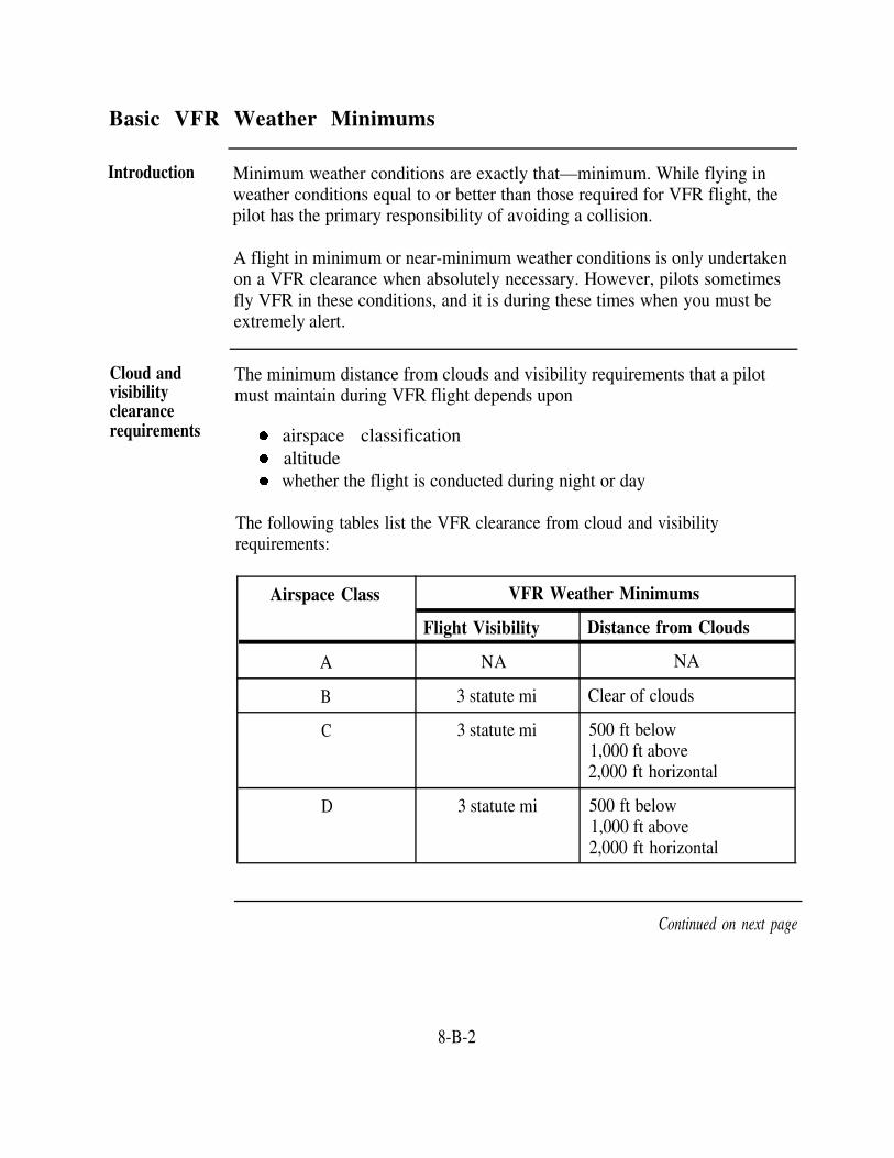
Basic VFR Weather Minimums
Introduction Minimum weather conditions are exactly that—minimum. While flying inweather conditions equal to or better than those required for VFR flight, thepilot has the primary responsibility of avoiding a collision.
A flight in minimum or near-minimum weather conditions is only undertakenon a VFR clearance when absolutely necessary. However, pilots sometimesfly VFR in these conditions, and it is during these times when you must beextremely alert.
Cloud andvisibilityclearancerequirements
The minimum distance from clouds and visibility requirements that a pilotmust maintain during VFR flight depends upon
airspace classificationaltitudewhether the flight is conducted during night or day
The following tables list the VFR clearance from cloud and visibilityrequirements:
Airspace Class VFR Weather Minimums
Flight Visibility Distance from Clouds
A NA
B 3 statute mi
C 3 statute mi
D 3 statute mi
NA
Clear of clouds
500 ft below1,000 ft above2,000 ft horizontal
500 ft below1,000 ft above2,000 ft horizontal
Continued on next page
8-B-2

Basic VFR Weather Minimums, Continued
Cloud andvisibilityclearancerequirements(continued)
Table continued from page 8-B-2.
Airspace Class VFR Weather Minimums
Flight Visibility Distance from Clouds
Less than 10,000 ft 500 ft belowE MSL—3 statute mi 1,000 ft above
2,000 ft horizontal
At or above 10,000 ft 1,000 ft belowMSL—5 statute mi 1,000 ft above
1 statute mi horizontal
G1,200 ft or less abovethe surface(regardless of MSLaltitude)—Day—1 statute mi Clear of clouds
Night—3 statute mi 500 ft below1,000 ft above2,000 ft horizontal
More than 1,200 ftabove the surface butless than 10,000 ftMSL—Day—1 statute mi 500 ft below
1,000 ft above2,000 ft horizontal
Night—3 statute mi 500 ft below1,000 ft above2,000 ft horizontal
Continued on next page
8-B-3

Basic VFR Weather Minimums, Continued
Cloud andvisibilityclearancerequirements(continued)
WeatherconditionsprecludingVFR flight
Table continued from page 8-B-3.
Airspace Class
G
VFR Weather Minimums
Flight Visibility Distance from Clouds
More than 1,200 ftabove the surfaceand at or above10,000 ft MSL—5 1,000 ft belowstatute mi 1,000 ft above
1 statute mi horizontal
When weather conditions encountered en route preclude compliance withVFR rules, a pilot can be expected to do one of the following:
Alter the route of flight so as to be able to continue under VFRconditionsRemain in VFR conditions until he or she can file a change of flightplan from the air and obtain an IFR clearanceRemain VFR and land at an alternate airport
8-B-4

Special VFR Operations
Introduction As an air traffic controller, you must be familiar with SVFR operations andunderstand what you can and cannot do in these situations and what to expectfrom the aircraft.
Special visual There are exceptions to the VFR weather minimums we have discussed.flight rules SVFR operations in weather conditions less than basic VFR minima may be(SVFR) conducted under the following conditions:
SVFR flights must remain clear of clouds.SVFR operations may be conducted within the lateral boundaries ofClass D and E surface areas and some Class B and C surface areasbelow 10,000 feet MSL.A SVFR clearance must be requested by the pilot.Weather conditions used for determining approval or disapproval of aSVFR request are based on the weather reported at the airport ofintended landing or departure.IFR traffic will not be unduly delayed because of the operation.Helicopters can operate in Class B, C, D, and E surface areas with lessthan 1 statute mile visibility.
Do not assign a fixed altitude when applying vertical separation. Ratherclear SVFR aircraft at or below an altitude that is at least 500 feet belowconflicting IFR traffic but not below the minimum safe altitude as prescribedin FAR, Part 91.
8-B-5

VFR Cruising Altitudes
Introduction There are cruising altitudes that apply to both VFR and IFR operations, andthey apply to flight in both controlled and uncontrolled airspace. At thispoint, we are dealing only with VFR cruising altitudes.
Cruisingaltitudes forVFR aircraft
The following tables list the appropriate altitudes for VFR flights based ondirection of flight:
More than 3,000 feet above the surface up to and including FL290
Magnetic course
0-179
180-359
Magnetic course VFR cruising altitude
0-179
VFR cruising altitude
Above FL290
180-359
Odd cardinal altitudes plus 500 feet(e.g., 3,500, 5,500, FL195, FL275,etc.)
Even cardinal altitudes plus 500 feet(e.g., 4,500, 8,500, FL205, FL285,etc.)
4,000-foot intervals starting withFL300 (e.g., FL300, FL340, FL380,etc.)
4,000-foot intervals starting withFL320 (e.g., FL320, FL360, FL400,etc.)
VFR cruisingaltitudeseparation
There are two distinct separation points in the structure of the separationsystem. The first point is at 3,000 feet AGL where cruising altitudes start;the second point is at flight level 290 (29,000 feet) where vertical separationincreases.
Continued on next page
8-B-6

VFR Cruising Altitudes, Continued
VFR cruisingaltitudeseparation(continued)
From 3,000 feet to flight level 290, opposite-direction traffic is separatedvertically by 1,000 feet.Above flight level 290, opposite-direction traffic is separated vertically by2,000 feet.
Separation of 1,000 and 2,000 feet may sound like more separation than isneeded, but sandwiched in between VFR cruising traffic is IFR cruisingtraffic.
Cruisingaltitudeselection
Two things need to be considered to determine a proper cruising altitude forVFR aircraft
The magnetic direction of intended flightThe desired altitude of the flight.
Taking these two items into account, we select the proper cruising altitude. Toillustrate, you can select a cruising altitude closest to 8,000 feet that would beappropriate for a magnetic course of 110°. Since 110° falls between 0° and179°, you should select 7,500 feet as the closest east-bound VFR cruisingaltitude to the desired altitude of 8,000 feet. The next closest cruisingaltitude for this direction of flight is 9,500 feet. Traffic in the otherdirection, west-bound or 180° through 359°, adheres to the standard of eventhousands plus 500.
Cruising altitudes above FL290 drop the plus 500 addition and advance to theadded separation factor. Notice that between 0° and 179° any flight levelbeginning at FL300 at 4,000-foot intervals is appropriate. Between 180° and359° any flight level at 4,000-foot intervals starting at FL320 is appropriate.
Exemptionsfrom VFRcruisingaltitudes
A VFR aircraft is exempt from complying with cruising altitudes when theaircraft is in one of the following situations:
Flying at or below 3,000 feet AGLIn a holding pattern with 2-minute legs or lessIn a turn
8-B-7


Section CInstrument Flight Rules
Overview
Introduction The effectiveness of Navy pilots depends largely upon their ability to operateaircraft in all types of weather conditions. To do this with a reasonabledegree of safety, you and the pilot must observe the basic regulations andcontrol procedures that govern IFR flight. Most FAR, Part 91, rules apply toboth military and civilian operations.
The Navy's express goal to decrease the probability of midair collisionsrequires that Navy pilots operate under IFR to the maximum extent possiblewithout unacceptable mission degradation. To meet this goal, the Navy hasadded several additional requirements.
In this section This section covers the following topics:
Topic See Page
Applicability 8-C-2
Takeoff Minimums 8-C-3
Minimum IFR Altitudes and IFR Cruising Altitudes 8-C-4
Landing Minimums 8-C-7
ATC IFR Clearance 8-C-8
8-C-1

Applicability
Introduction To understand and apply IFR flight rules, you must know where and whenthese rules apply.
FAR FAR 91.115 states "No person may operate an aircraft in controlled airspacerequirement under IFR unless:
1. An IFR flight plan has been filed, and2. An appropriate ATC clearance has been received."
IFR compliance Pilots must comply with IFR procedures when operating their aircraft inweather conditions that are less than VFR minimums. Additionally, Navypilots are encouraged to use IFR procedures when their flights are conductedwithin the federal airway system.
Pilots must adhere to IFR procedures in the following situations:
When conducting flights along jet routes (Operations parallel to andwithin 10 miles of the established centerline are considered to be alongthe route.)When operating in Class A airspaceDuring flights to and from targets or operating areas when feasibleWhen performing instrument approaches
When VFR conditions exist, a pilot may waive any of the above fourrequirements for a specific flight when he or she needs to circumnavigate orotherwise avoid severe weather or when an in-flight emergency dictates suchaction.
8-C-2

Takeoff Minimums
Introduction
Application oftakeoffminimums toNavy pilots
Standardinstrumentrated pilottakeoff request
Specialinstrumentrated pilottakeoff request
Pilot ceiling and visibility takeoff minimums ensure that a pilot can return tothe departure airport and land if an emergency should develop shortly aftertakeoff. FAR 91.116 contains takeoff minimums for civilian airports.
The instrument rating of a Navy pilot determines if he or she is subject totakeoff ceiling and visibility minimums at a naval air station. A pilot'squalifications and experience determine the rating.
A Navy pilot with a standard instrument rating must adhere to ceiling andvisibility minimums before he or she requests a takeoff.
A Navy pilot with a special instrument rating has no minimums.
A standard instrument rated pilot must observe to the following minimumswhen he or she requests takeoff:
A 300-foot ceiling and a l-statute-mile visibility unless the air station hasPAR with published minimums less than 300 and 1.With PAR, weather must at least be equal to the precision approachminimums for the runway in use. The ceiling cannot be less than 200 feetand visibility cannot be less than 1/2 statute mile or a 2,400-foot RVR.
A special instrument rated pilot requests takeoff based upon his or herjudgment and the urgency of the flight. Special instrument rated pilots haveno ceiling or visibility takeoff minimums.
8-C-3

Minimum IFR Altitudes and IFR Cruising Altitudes
Introduction Except when landing or taking off, an IFR aircraft must maintain an altitudethat is no lower than the established minimum IFR altitude for its position.This altitude is the lowest altitude that permits safe flight with regard to theterrain, the weather conditions, and the navigational facilities available. Insome cases, the Navy has established additional minimums for its aircraft thatare more restrictive than civilian minimums.
Minimum IFR Minimum IFR altitudes appear on charts as one of the following data elements:altitudes onairways Minimum en route IFR altitudes (MEA)
Minimum obstruction clearance altitude (MOCA)Minimum crossing altitude (MCA) (The MCA is the minimum altitude thatan aircraft can cross a fix or reporting point along an airway.)
For further information, refer to the FAR, Part 91.
No published Operations in uncontrolled airspace include operations like point-to-pointminimum IFR flight. Uncontrolled airspace does not have published MEAs or MOCAs andaltitudes the following minimum IFR altitudes apply:
For Navy aircraft
Areas Minimum altitude above thehighest obstacle within 22 miles of
the centerline of an intendedcourse
Over designated mountainous terrain 2,000 ft
Other than mountainous areas 1,000 ft
Continued on next gage
8-C-4

Minimum IFR Altitudes and IFR Cruising Altitudes, Continued
No published For civilian aircraftminimum IFRaltitudes(continued)
Areas
Over designated mountainous terrain
Other than mountainous areas
Minimum altitude above thehighest obstacle within 4 miles of
the centerline of an intendedcourse
2,000 ft
1,000 ft
Continued on next page
8-C-5

Minimum IFR Altitudes and IFR Cruising Altitudes, Continued
IFR Altitudeassignment
IFR aircraft should be cleared to the appropriate altitudes as depicted in thetable below:
On courseAircraftOperating degress Assign Examples
magnetic
Below 3,000 Any course Any altitudefeet abovesurfaceBelow FL 290 0 through 179 Odd cardinal 3,000 5,000,
altitude or FL250,flight levels at F270intervals of2,000 feet
180 through Even cardinal 4,000, 6,000,359 altitude or FL240,
flight levels at FL 260intervals of2,000 feet
At or above 0 through 179 Odd cardinal FL290,FL 290 flight levels at FL330,
intervals of FL3704,000 feet be-ginning withFL 290
180 through Odd cardinal FL310,359 flight levels at FL350,
intervals of FL3904,000 feet be-ginning withFL 310
Aircraft On course
Operatingdegrees Assign Examples
magnetic
One way routes Any course Any cardinal FL270, FL280,(except in altitude or FL310,composite flight level FL330systems) below FL 290
or any oddcardinal flightlevel at orabove FL 290
Within an Any course Any altitude orALTRV flight level
In transition to/ Any course Any odd or Fl280, FL290,from or within even cardinal FL300,Oceanic flight level FL310,airspace where including those FL320,composite above FL 290 FL330,separation is FL340authorized
In aerial Any course Altitude blocks 050B080,refueling tracks as requested. FL180B220,and anchors Any altitude or Fl280B310
flight level
8-C-6

Landing Minimums
Introduction
Ceiling andvisibility
At or aboveminimumsbefore startingapproach
Belowminimumsbefore startingapproach
Belowminimumsduringapproach
Instrument approach procedures and landing minimums are published in DoDflight information publications (terminal) or other similar publications. Youshould understand approach procedures and the minimums for your airfield.
The absolute minima for a single-piloted Navy aircraft executing a precisionapproach is a 200-foot ceiling with 1/2-mile visibility (2,400-foot RVR) orpublished minima, whichever is higher. An entire airfield is below minimumswhen the existing visibility is lower than the lowest published visibility for anoperative navigation or approach aid. An airport's prevailing visibility is thecontrolling factor for approaches that require an aircraft to circle to anotherrunway. Prevailing visibility also controls straight-in approaches when RVR orRVV information is not available.
A pilot is permitted to start an approach (or a high-altitude penetration for anapproach) when the reported terminal weather indicates that existing ceilingand visibility are at or above the published approach minimums.
Normally, the pilot will request clearance to a holding fix or clearance to analternate airport when the weather is below minimums.
A multipiloted Navy aircraft may begin an approach after receiving aweather report that below minimum weather conditions exist provided theaircraft can proceed to a suitable alternate airport in the event of a missedapproach.
When a pilot began the approach or penetration before obtaining the necessaryweather information, he or she may continue the approach to the missedapproach point. If the pilot sights the runway, approach lights, etc., he or shemay proceed to land.
NOTE: Determination that existing weather or visibility is adequate forapproach or landing is the responsibility of the pilot.
8-C-7

ATC IFR Clearance
Introduction A pilot must receive an IFR clearance before flying IFR in controlledairspace. The clearance is given by the ATC facility having IFR authorityover the airspace in which the flight is to be conducted.
Required items The required items of an IFR clearance are as follows:of a clearance
Aircraft's identificationA clearance limitThe departure procedure or SIDRoute of flightAltitude data (in the order to be flown)Holding instructions, if necessarySpecial information, if anyRadio frequency assignmentRadar beacon code assignment
Deviations from Once the pilot requests and receives an IFR clearance, that pilot may nota clearance deviate from this clearance without permission. If a deviation is needed or
made for emergency reasons, the pilot must notify the controlling agency assoon as possible. The agency then issues another clearance or amends theoriginal clearance. Nothing, however, prevents a pilot from canceling theIFR clearance and proceeding under VFR.
8-C-8

Section DSecurity Control of Air Traffic (FAR, Part 99)
Overview
Introduction
In this section
FAR, Part 99, prescribes rules for operating aircraft in a defense area, orinto, within, or out of the United States through an ADIZ.
This section covers the following topic:
Topic See Page
Security Control of Air Traffic 8-D-2
8-D-1

Security Control of Air Traffic
Introduction National security in the control of air traffic is governed by FAR, Part 99,and Security Control of Air Traffic and Air Navigation Aids (SCATANA),OPNAVINST 3722.30, for the Navy. All aircraft entering domestic U.S.airspace from points outside, must provide for identification before entry.To facilitate early aircraft identification of all aircraft in the vicinity of theUnited States and its international airspace boundaries, ADIZs have beenestablished. Pilots of aircraft must follow specific operational requirementswhen entering an ADIZ.
Flight Plan A flight plan must be on file in all ADIZ and DEWIZ areas. The flight planmay be either IFR or DVFR. In some cases, the flight plan must beapproved by you, an air traffic controller, before departure. An air filedVFR flight plan makes an aircraft subject to interception for positiveidentification. Therefore, pilots are urged to file the required DVFR flightplan either in person or by telephone before departure.
Two-way radio An operative, two-way radio must be available in all ADIZ and DEWIZareas. If an aircraft is operating on a DVFR flight plan and two-way radiocommunications cannot be maintained, the pilot may proceed according to theoriginal DVFR flight plan or land as soon as possible. Either way, the pilotmust report the radio failure to an appropriate aeronautical facility as soon aspossible.
If an aircraft is operating within an ADIZ or DEWIZ under an IFR flightplan and two-way communications cannot be maintained, the pilot willproceed in accordance with FAR, Part 91.
Positionreporting
Normal IFR position reports are required in all ADIZ and DEWIZ areas. Inthe domestic and coastal ADIZ areas, flight under DVFR flight plans mustgive the estimated time of ADIZ penetration at least 15 minutes beforepenetration. In the coastal ADIZ, inbound foreign aircraft must report atleast 1 hour before ADIZ penetration.
Continued on next page
8-D-2

Security Control of Air Traffic, Continued
Aircraftpositiontolerances
Estimated points and times of ADIZ penetration are just that-estimates.Thus, some tolerances are allowed.
Over land, the tolerance is ±5 minutes from the estimated time over areporting point or point of penetration and within 10 nautical miles from thecenterline of an intended track over an estimated reporting point or point ofpenetration.
Over water, the tolerance is ±5 minutes from the estimated time over areporting point or point of penetration and within 20 nautical miles from thecenterline of the intended track over an estimated reporting point or point ofpenetration.
Exemptions Aircraft operating within an ADIZ may be exempted from the nationalsecurity requirements of FAR, Part 99 (except for special security instructionsissued by the administrator in the interest of national security), if the aircraftis operating in the following:
Within the 48 contiguous states and the District of Columbia,or within Alaska, and remains within 10 miles of the departurestationAny ADIZ other than the contiguous U.S. ADIZ when theaircraft's true airspeed is less than 180 knotsOver or within 3 nm of the coastline of any island in theHawaiian Coastal ADIZ
NOTE: Locally, the ARTCC can authorize deviations from FAR, Part 99,for some ADIZ operations.
8-D-3


CHAPTER 9
CONTROL TOWER OPERATIONS
Overview
Introduction At any location where terminal air traffic control (ATC) operations areconducted, the control tower is the hub of the ATC complex. From this hub allclearances for landings and takeoffs originate. This is the case even though theaircraft may be under the direct control of a radar approach control or groundcontrolled approach (GCA) facility. The tower local controller is the finalauthority in determining the use of the runway. When both VFR and IFR airtraffic are arriving and departing, the tower controller takes and coordinatesactions needed to blend these operations into an orderly flow of traffic.
Your job as the air traffic controller is to effect the safe, orderly movement ofaircraft. You must also control vehicular and pedestrian traffic on the airfield.To do these jobs, you use radios and other signaling devices to provideinformation and instructions relative to the traffic and airport conditions.
This chapter introduces you to the primary duties of a tower controller and tothe control procedures you must use.
Objectives The material in this chapter will enable you to:
Identify the operating positions in a basic control towerIdentify responsibilities of control tower personnel for each operatingpositionIdentify general procedures applicable to control tower operationsIdentify the component parts of standard traffic patternsState the landing and sequencing information given to pilotsState those procedures that pertain to special operations
Continued on next page
9-1

Overview, Continued
Acronyms The following table contains a list of acronyms that you must know tounderstand the material in this chapter:
Acronym Meaning
AC Navy air traffic controller
ATC Air traffic control
ATIS
CARF
CD
Automatic terminal information service
Central altitude reservation function
Clearance delivery position
CTO Control tower operator
FAA
FCLP
FD
FDIO
GC
Federal Aviation Administration
Field carrier landing practice
Flight data position
Flight data input/output
Ground controller
GCA Ground-controlled approach
IFR Instrument flight rules
LC
LSO
NOAA
NOTAM
SAFI
SAR
SVFR
Local controller
Landing signal officer
National Oceanic and Atmospheric Administration
Notice to airmen
Semiautomatic flight inspection
Search and rescue
Special visual flight rules
Continued on next page
9-2

Overview, Continued
Acronyms(continued)
Table continued from page 9-2.
Acronym Meaning
USAF U.S. Air Force
VFR Visual flight rules
Topics This chapter is divided into four sections:
Section Topic See Page
A Tower Operating Positions and Responsibilities 9-A-1
B General Control Tower Procedures 9-B-1
C Traffic Patterns 9-C-1
D Arrival and Departure Procedures 9-D-1
E Special Operations 9-E-1
9-3


Section ATower Operating Positions and Responsibilities
Overview
Introduction This section covers the operating procedures and responsibilities of controltower personnel. This is basic information; for more detailed information,refer to NATOPS Air Traffic Control Facilities Manual, NAVAIR 00-80T-114.
In this section This section covers the following topics:
Topic
Control Tower Responsibilities
See Page
9-A-2
Operating Positions 9-A-4
9-A-1

Control Tower Responsibilities
Introduction Establishment of controller positions varies according to local requirementsand type of facility, but those included in most control towers are the localcontrol position, ground control position, and the flight data position.Clearance delivery may or may not be located in the control tower.
Responsibilities The hub of airport operations is the control tower. It is elevated to a suitableheight to afford the maximum visibility of the airport and the immediate area.The primary objective of the control tower is to promote the safe, orderly,and expeditious movement of air traffic. This includes the following:
Aiding pilots in preventing collisions between aircraft and betweenobstructions and aircraft in the movement areaExpediting and maintaining an orderly flow of air trafficAssisting the pilot of an aircraft by providing advice needed for thesafe and efficient conduct of the flightNotifying appropriate organizations regarding aircraft known orbelieved to be in need of search and rescue aid and assisting suchorganizations as required
The control tower exercises control of all aircraft operating on or around anairfield; all movements of aircraft must have prior approval from the controltower. This includes instructions and permission to tow, taxi, takeoff, land,and related aircraft operations.
Continued on next page
9-A-2

Control Tower Responsibilities, Continued
Control tower The control tower log is kept from watch to watch in all Navy controllogs towers. It contains all the pertinent data accumulated during each watch
performed in the control tower. A partial listing of the data that is entered inthe record or log includes status of equipment, check of communications,status of airport lighting facilities, runway or runways in use, and otherinformation deemed necessary by the control tower chief or tower supervisor.
A position log is also maintained for each operating position in the tower.The purpose of this log is to establish a reliable record of position manning.These logs must contain the date, time, position and controller-operatinginitials. (If the position is operated by a trainee, his or her initials will beentered after those of the controller responsible for the position.)
Daily and To facilitate completion of certain reports required of the ATC division, amonthly traffic daily and monthly tabulation of aircraft operations is needed. Flight progresstabulation strips are a main source of traffic count information. These strips are kept
for 3 months before they are destroyed. If any strip contains information onan aircraft involved in an accident or emergency, it is kept for a longerperiod of time. If installed, another source of traffic count information is theAir Traffic Activity Analyzer (ATAA).
A compilation of all operations is submitted annually to the Chief of NavalOperations. This report is referred to as the Air Traffic Activity Report.Instructions for completing this report are in the NATOPS Air Traffic ControlFacilities Manual, NAVAIR 00-80T-114.
9-A-3

Operating Positions
Introduction
Towersupervisor
Navy control towers require several operating positions. Operating positionsmay be added, deleted, combined, or integrated as necessary to meet localrequirements. Brief descriptions of tower operating positions with theirresponsibilities follow. Refer to NATOPS Air Traffic Control FacilitiesManual, NAVAIR 00-80T-114, for more detailed information.
The tower supervisor is responsible to the FWS for the operational efficiencyof the control tower watch team. The tower supervisor must possess a CTOrating for the control tower to which he or she is assigned. Primary duties ofthe tower supervisor include the following:
Coordinating and directing control of aircraft operating in assignedairspace, and coordinating and directing air traffic and surface vehiclesoperating on runways, taxiways, and other airfield movement areasBriefing the control tower watch team on weather conditions, airtraffic, equipment status, field conditions, and special evolutionsAssigning personnel to operating positions according to individualqualifications and training requirementsAssigning trainees to qualified controllers for supervision and trainingNotifying cognizant SAR agencies of aircraft in distress and providingassistance and advice during emergenciesWhen the airfield is technically VFR, but visual separation cannot bemaintained, taking immediate action to suspend VFR operations andinforming appropriate authorities
Local controller The LC maintains a continuous visual surveillance of control tower airspace,runways, and other movement areas. Primary duties of the LC include thefollowing:
Formulating and issuing clearances and control instructions toaccomplish separation between aircraft and between aircraft andvehicles operating under the jurisdiction of the towerEffecting coordination with appropriate operator positions and otherfacilitiesProviding flight assistance service to aircraft
Continued on next page
9-A-4

Operating Positions, Continued
Local controller(continued)
Operating airport lighting, lighting systems, and visual landing aidsInitially notifying and dispatching emergency personnel and equipmentfor aircraft emergencies and accidents.
Ground The GC provides general surveillance of the airport movement area. Primarycontroller duties of the GC include the following:
Flight dataposition
Clearancedeliveryposition
Operatingpositioncoordination
Formulating and issuing ground movement clearances to aircraft andvehicles operating on the airportTransmitting current weather and field conditions as required
The duties of the FD position are as follows:
Operating interphones and telephones and other communicationsequipment as neededReceiving and relaying aircraft movement dataPreparing and posting flight progress stripsOperating ATIS and FDIO equipmentMonitoring navigational aid alarm systems
The duties of the CD position are as follows:
Obtaining, posting, and relaying ATC clearances and advisoriesOther duties as assigned by the tower supervisor
Operating position coordination involves the use and integration of allavailable skills and resources to achieve and maintain watch team efficiency,situational awareness, and mission effectiveness. Air Traffic Control, FAAOrder 7110.65 discusses local controller and ground controller coordinationrequirements concerning a variety of items.
9-A-5


Section BGeneral Control Tower Procedures
Overview
Introduction This section will provide you with information that you will be required toknow and utilize as a tower controller. The information is from the AirTraffic Control, FAA Order 7110.65, however there are other manuals aswell as local procedures that you will also be required to use.
In this section This section covers information on the following topics:
Topic See Page
Advisory Information 9-B-2
Field Information
Runway Use and Conditions
9-B-5
9-B-6
Priority 9-B-8
9-B-1

Advisory Information
Introduction As a tower controller, you must know when and how to use advisoryinformation to assist the pilot. Advisory information is important because itcan make the difference between a safe landing and a tragedy.
As an air traffic controller, you provide ATC service based upon observed orknown traffic and airport conditions that might constitute a hazard.
Movement You should issue specific approval or disapproval for movement of vehicles,areas equipment, or personnel on the movement area via radio or light signal gun.
Conditionalphrases
You should not qualify approval of specific situations by conditional phrasessuch as BEHIND LANDING TRAFFIC, or AFTER THE DEPARTINGAIRCRAFT. Personnel can interpret movement instructions withconditional phrases in more than one way. This can cause unsafe movementon the airfield.
Clearances Air traffic and runway conditions should be the controlling factor indetermining whether you deny a clearance to takeoff, to land, to make a lowapproach, or to make touch-and-go. A closed runway or below weatherminimums conditions might also warrant denying a specific aircraft clearancerequest. However, a landing clearance cannot be withheld indefinitely.
Should a pilot request to use a closed runway, inform the pilot that therunway is closed and, if necessary, quote the appropriate parts of theNOTAM applying to the runway.
Landing gearchecks
If a pilot is not sure that the landing gear is down and locked, the pilot mustnotify the control tower. You then instruct the pilot to perform a low pass infront of the tower for a visual check. Then relay to the pilot the results ofthe visual check.
Continued on next page
9-B-2

Advisory Information, Continued
Landing gearchecks(continued)
Unusualmaneuvers
Bird activity
Weatherinformation
Should any doubt exist after a visual check, alert the crash and rescueequipment and the aircraft pilot. The pilot should then make a precautionarylanding. After the landing rollout, the aircraft should not be turned off therunway until ground personnel have made a visual check of the landing gearand installed the gear pins (if applicable).
Do not approve pilot requests or ask a pilot to conduct unusual maneuverswithin a control tower's airspace if such maneuvers are not essential to theperformance of the flight. These unusual maneuvers include unnecessary lowpasses, unscheduled fly bys, practice instrument approaches to altitudesbelow specified minima (unless a landing or touch-and-go is to be made), orany so-called "buzz jobs" wherein flight is conducted at low altitude or ahigh rate of speed for thrill purposes. Such maneuvers increase hazards topersons and property and contribute to noise complaints.
You should issue bird activity information including position, size, andspecies (if known), and their course of flight and altitude to pilots of theaircraft concerned for at least 15 minutes after receipt of the informationfrom pilots or adjacent facilities. You may reduce this time when eithervisual observations or subsequent reports reveal that the bird activity is nolonger a factor. Relay bird activity information to adjacent facilitieswhenever it appears it will become a factor in their areas.
You may transmit to pilots or other ATC facilities, without consultingweather service personnel, elements of weather information derived directlyfrom your instruments, from your radar, or received by your tower as a pilotreport. You may also transmit observed weather conditions such as LARGEBREAKS IN THE OVERCAST, VISIBILITY LOWERING TO THESOUTH, or similar statements that do not include specific values. Terminalradar control facilities that provide approach control service to your controltower should inform your tower of storm areas they observe on radar.
Continued on next page
9-B-3

Advisory Information, Continued
Weatherinformation(continued)
A weather observation that includes specific values (such as ceilings andvisibility) must have been made or verified by weather personnel before youtransmit it. If you are a certified tower visibility observer and the visibility isless than 4 miles, you may also transmit your visibility observations.
You should inform local weather service personnel of any differencesbetween weather conditions observed from the tower and those reported byweather service.
9-B-4

Field Information
Introduction The tower controller should issue pertinent field condition informationnecessary for an aircraft's safe operation in time for it to be useful to thepilot.
Field The tower controller must issue the following information concerning fieldinformation conditions to any pilots concerned:
Other field conditions considered pertinent by the controller
Parked aircraft on the movement areaIrregular operation of part or all of the field lighting systemVolcanic ash on any airport surface and, if known, whether the ash iswet or dry
Construction work on or immediately adjacent to the movement areaRough portions of the movement areaBraking conditions caused by ice, snow, slush, or waterSnowdrifts or piles of snow on or along the edges of the area; also theextent of any plowed area
The tower controller should describe field conditions clearly and concisely.
9-B-5

Runway Use and Conditions
Introduction The tower controller provides pilots with runway use authorization andrunway condition information.
Runwayselection
For aircraft operations, you should select the runway most nearly alignedwith the wind when the wind velocity is 5 knots or more or the calm-windrunway when the wind velocity is less than 5 knots. An exception to theseprocedures exists when an airfield has a "runway use" program because ofnoise abatement or other local restrictions.
You must issue both wind direction and velocity when authorizing the use ofrunways. You must do this even though the wind velocity is less than 5knots and the calm wind runway is to be used. Since some aircraft areadversely affected by a tailwind or crosswind component, pilots must beaware of the exact wind condition to conduct a safe flight. Therefore, youshould describe the wind condition as "calm" only when the velocity is lessthan 3 knots.
Use of another runway is permissible if it will be operationally advantageousor if it is requested by a pilot. If a pilot prefers to use a runway differentfrom that which you specify, he or she is expected to advise you accordingly.
Whenever you clear a pilot for operations on other than the advertised activerunway, you must state the runway number.
Runway useprograms
Runway use programs for large aircraft and turbojet aircraft are set up atsome airports. In such programs, runway assignment is affected byconsideration of noise-sensitive areas and noise-abatement benefits, not windvelocity. Acceptance or refusal of such assignments is still the pilot’sprerogative.
Adverse At facilities affected by winter weather conditions, runway condition andrunway braking action are important information that you must relay to pilots whenconditions adverse conditions exist on the landing area.
Continued on next page
9-B-6

Runway Use and Conditions, Continued
Critical phases The final approach, touchdown, landing roll, takeoff, and initial climb to theof flight first turnaway from the airfield are the most critical phases of flight. Theseconsiderations phases require the full attention of the pilot. Except during radar approaches
or departures, you must refrain from transmitting to the aircraft during thesephases of the operation unless conditions affecting safety of flight exist. Youmust transmit safety-of-flight considerations, including airfield conditions, atany time you observe them, or they are made known to you.
9-B-7

Priority
Introduction
Exceptions tonormal
The normal priority for ATC service is first-come, first-served.
The tower controller should provide first-come, first-served service exceptfor in the following situations:
Priority to civilian air ambulance flights "LIFEGUARD." Priority tomilitary air evacuation flights when verbally requested. Assist airambulance or evacuation aircraft to avoid areas of significant weatheror turbulent conditions.Maximum assistance to SAR aircraft that are performing a SARmission.Expedite the movement of presidential aircraft and entourage and anyrescue support aircraft as well as related control messages when trafficconditions and communications facilities permit.Special handling, as required, to expedite Flight Check aircraft.Expedite movement of NIGHT WATCH aircraft when NAOC isindicated in the remarks section of the flight plan or in air/groundcommunications.Expeditious handling for any civil or military aircraft using the codename FLYNET.Expeditious handling of aircraft using the code name "Garden Plot"only when CARF notifies you that such priority is authorized.Special handling for USAF aircraft engaged in aerial samplingmissions using the code name "SAMP."Maximum assistance to expedite the movement of interceptor aircrafton active air defense missions until the unknown aircraft is identified.Expedite movement of Special Air Mission aircraft when SCOOT isindicated in the remarks section of the flight plan or in air or groundcommunications.When requested, priority handling to TEAL and NOAA missionaircraft.IFR aircraft shall have priority over SVFR aircraft.
Continued on next page
9-B-8

Priority, Continued
Exceptions tonormal(continued)
Priority and special handling to expedite the movement of OPENSKIES observation and demonstration flights.Aircraft operating under the National Route Program are not subject toroute limiting restrictions (i.e., published preferred IFR routes, letterof agreement requirements).
No set priorities can be prescribed for the handling of aircraft experiencingemergencies because of the infinite variety of possible situations that mayoccur.
NOTE: Aircraft in distress have the right of way over all other traffic.
9-B-9


Overview
Section CTraffic Patterns
Introduction Two types of traffic patterns are established at each airfield:
The standard traffic patternThe overhead approach pattern
Normally, traffic patterns provide for left traffic flows; however, right trafficflows are used when required or deemed necessary by the controller andpilot.
In this section This section covers the following topics:
Topic See Page
Standard Traffic Pattern 9-C-2
Overhead Approach Pattern 9-C-4
Landing Information 9-C-6
9-C-1

Standard Traffic Pattern
Introduction The standard traffic pattern is used throughout the Navy. The altitudes forthis pattern may vary due to the air station's geographic location or themission of the aircraft assigned. Additionally, aircraft operationalrequirements may compel a slight modification to pattern entry procedures.However, the basic pattern parts remain the same.
Under normal conditions, the flow of traffic is counterclockwise, and thepilot makes left turns in the traffic pattern.
Traffic pattern The standard traffic pattern components are the upwind leg, the crosswindcomponents leg, the downwind leg, the base leg, and the final approach. The traffic
pattern components are depicted below.
Traffic pattern A description of each traffic pattern component follows.componentdescriptions UPWIND LEG.—The upwind leg is a flight path parallel to the landing
runway in the direction of landing.
CROSSWIND LEG.—The crosswind leg is a flight path at right angles to thelanding runway off its upwind end.
Continued on next page
9-C-2

Standard Traffic Pattern, Continued
Traffic pattern DOWNWIND LEG.—The downwind leg is a flight path parallel to thecomponentsdescriptions
landing runway in the direction opposite to landing. The downwind leg
(continued)normally extends between the crosswind leg and the base leg.
BASE LEG.—The base leg is a flight path at right angles to the landingrunway off its approach end. The base leg normally extends from thedownwind leg to the intersection of the extended runway centerline.
FINAL APPROACH.—The final approach is a flight path in the direction oflanding along the extended runway centerline. The final approach normallyextends from the base leg to the runway. An aircraft making a straight-inapproach VFR is also considered to be on final approach.
Downwind Sometimes due to a traffic situation, an emergency, or other aircraftentry operational requirements, a pilot must perform a downwind entry.
A downwind entry is a pattern entry where the pilot enters the standardtraffic pattern at a forty-five degree angle to the downwind leg. A downwindentry is depicted below.
9-C-3

Overhead Approach Pattern
Introduction The overhead approach pattern is a series of predetermined maneuversprescribed for VFR arrival of military aircraft (often in formation) for entryinto the VFR traffic pattern. This pattern allows high-performance aircraft,such as fighters and certain types of trainers, to transition into the terminalarea simultaneously with slower aircraft that are flying a standard trafficpattern.
Overheadapproachpatterncomponents
The components of the overhead approach pattern are initial approach, breakpoint, "the 180", and final approach. The overhead approach patterncomponents are depicted below.
Overheadapproachpatterncomponentdescriptions
A description of the component parts of the overhead approach patternfollows:
INITIAL APPROACH.—This is a line-of-flight that follows the extendedcenterline of the landing runway. Initial approach varies in length from 3 to5 miles. Normally, an aircraft flies the initial approach part of an overheadapproach 500 feet above the elevation of the standard traffic pattern for theairfield.
Continued on next page
9-C-4

Overhead Approach Pattern, Continued
Overheadapproachpatterncomponentsdescriptions
Visual holdingof VFR aircraft
BREAK POINT.—This is a point, normally just above the landing threshold,where the aircraft is turned (left or right, depending on the direction of trafficflow) 180° so as to be on the downwind leg.
"The 180".—After the downwind leg segment, a second 180° turn is made soas to establish the aircraft on final approach. Up until the time that thesecond 180° turn is started, the aircraft remains at the traffic pattern altitude.
FINAL APPROACH.—Regardless of the type of aircraft or the type ofapproach, all arriving aircraft must fly at least one common component of astandard traffic pattern—final approach. Rollout on final approach must notbe less than 1/4 mile from the landing threshold and not less than 300 feetabove the ground.
NOTE: If the pilot does not intend to make a full stop landing from anoverhead approach, he or she enters the standard traffic pattern after lowapproach or touch-and-go.
Often, you will need to hold arriving VFR aircraft to adjust the flow oftraffic. When this becomes necessary, clear the aircraft to hold at selected,prominent geographical fixes that are easily recognized from the air. If youhave more than one aircraft holding at the same fix, issue traffic information.
Issue the following additional landing information to aircraft that will conductan overhead approach:
If needed, request the pilot to report the "Initial."If required for traffic reasons, request that the pilot report the "Break."Specify the point of break if it is nonstandard or you desire to change thebreak point for traffic reasons.
Traffic pattern altitude and direction of turns. You may omit either orboth when they are standard or you know that the pilot is familiar with anonstandard procedure.
9-C-5

Landing Information
Introduction To ensure a safe and orderly flow of air traffic, you must provide the pilotwith certain essential landing information. This information enables the pilotto set up his or her aircraft for the correct VFR traffic pattern entry.
ATISinformation
You should provide landing information to arriving aircraft when youestablish initial radio contact. You may omit items of information if they arecontained in the ATIS broadcast and the arriving pilot states the correct ATIScode.
"Havenumbers"
Another procedure you may encounter that greatly reduces frequencycongestion is the term have numbers. In terminal areas where ATIS is notprovided, a pilot may monitor the tower local frequency for enough timebefore initial contact to determine routine landing information. Upon makinginitial contact, the pilot will use the term have numbers or a similar phrase toindicate that he or she has received the runway, wind, and altimeter setting.Upon hearing the pilot use this term or similar phrase, you may omit theseitems when issuing landing information. Otherwise, you must issue landinginformation.
Requiredlandinginformation
The following information should be relayed to arriving aircraft:
Specific traffic-pattern information, such as enter left base, enter rightbase, make straight-in, or make right traffic. This type of informationmay be omitted if the aircraft is to circle the airport to the left.Runway in use.Surface wind.Altimeter setting.Any supplementary information.Clearance to land.
Continued on next page
9-C-6

Landing Information, Continued
Requiredlandinginformation(continued)
Request for additional position reports. Use prominent geographical fixeswhich can be easily recognized from the air, preferably those depicted onsectional charts. The legs of the traffic pattern can also be used. Undernormal conditions, after landing information has been issued, furthercommunications between the controller and the pilot are not required untilthe aircraft reports entering the traffic pattern. When the pilot reportsentering the pattern, you then sequence the aircraft into the pattern forlanding.Ceiling and visibility if either is below basic VFR minimums.When available, low-level wind shear advisories.Braking action for the runway in use received from pilots or theOperations Duty Officer when Braking Action Advisories are in effect.
Wheels-downcheck
Remind pilots to check for wheels down on the aircraft at an appropriateposition in the traffic pattern. The intent is solely to remind the pilot. Youmay omit this reminder if the pilot reports the aircraft's wheels are down.
9-C-7


Section DArrival and Departure Procedures
Overview
Introduction As a tower controller, you are responsible for arrival and departuresequencing and separation. To do this properly, you must be familiar withthe rules and procedures regarding tower separation and sequencing includingtraffic patterns and runway usage.
The material in this section will not cover all situations. Your facility mayhave special or unique operations that will be covered in your facilitymanuals. You should understand and be able to use all the procedures foryour field. Not knowing or understanding a procedure while you arecontrolling usually has a snowball effect that usually has a negative affect onsafety.
In this section This section covers the following topic:
Topic See Page
Arrival and Departure Sequencing and Separation 9-D-2
9-D-1

Arrival and Departure Sequencing and Separation
Introduction Arrival and departure sequencing and separation starts and ends at therunway environment. As a tower controller, you play a vital role inestablishing proper separation and sequencing. The rules and procedures thatyou must follow are contained in Air Traffic Control, FAA Order 7110.65.Remember, your facility may have unique procedures that have specialrequirements that you must also be familiar with. These special requirementsare normally published in air operation and facility manuals.
Sequencing and When working in a control tower, you will need to know the sequencing andseparation separation procedures that are outlined in Air Traffic Control, FAA Ordercriteria 7110.65, chapter 3, "Airport Traffic Control."
Objectives The information in Air Traffic Control, FAA Order 7110.65, chapter 3,"Airport Traffic Control" will enable you to:
State the minimum separation standards between arriving aircraftState those procedures that pertain to fixed-winged departuresState those procedures that pertain to helicopter operations
9-D-2

Overview
Section ESpecial Operations
Introduction Many naval air stations conduct special flight operations required to completethe military training mission. Aerial tow targets and FCLPs are two of thesetypes of operations.
In this section This section covers the following two topics:
Topic See Page
Aerial Tow Target Operations 9-E-2
FCLP Operations 9-E-3
9-E-1

Aerial Tow Target Operations
Introduction Aerial tow targets and related equipment are used for gunnery practice byships and shore installations as well as for air-to-air firing exercises in specialuse airspace.
Towing operations enable gunners to fire at targets that simulate movingaircraft in speed, shape, and maneuvers.
Manual tow Most aerial tow targets can be released or trailed behind the aircraft in flighttarget and retracted or dropped when the mission is completed. Also, tower patternoperations and sequencing adjustments may be required during these tow target
operations.
Tow targetmalfunction
If a mechanical malfunction exists, the pilot may not be able to retract thetow target. In such cases, the pilot may decide to make a low approach overthe airport and drop the target in an area from which it could be retrieved.The local Air Operations Manual designates specific procedures and areas fordropping towed targets.
An aircraft with a tow target in the traffic pattern is a definite hazard and youmust control traffic accordingly. You may require additional spacing oftraffic or have other traffic vacate the traffic pattern until the tow drop iscomplete.
9-E-2

FCLP Operations
Introduction Involvement of the air traffic controller during FCLP operations stems fromthe AC's responsibility to control aircraft at and around the airport. The ACis called upon to exercise control and to handle other tasks connected withFCLP operations.
FCLPs Pilots receive an extensive training program at shore installations to preparethem for actual carrier landings. FCLP provides this training. The LSO is incharge of FCLP operations. An LSO is an experienced carrier pilot whom theNavy has designated to assist and instruct pilots in carrier and field carrierlanding techniques. The LSO is directly responsible for the aircraft in theFCLP pattern with the local controller maintaining overall responsibility for theseparation and sequencing of aircraft in all the tower patterns (FCLP included).
To approximate shipboard landing conditions, simulated flight deck markingsare painted on the runway landing area. Lights outline the carrier deck fornighttime use. These lights may be either fixed, portable, or smudge pots.
The FCLP pattern is usually a touch-and-go pattern.
operations
LSO During FCLP operations, the LSO has the following responsibilities:responsibilitiesduring FCLP Except when a hazardous condition exists, gives all instructions to the
pilots of aircraft in the FCLP pattern.In FCLP final approaches, controls aircraft. The LSO may, at his of herdiscretion, waveoff an aircraft at any point in the landing approach.
Continued on next page
9-E-3

FCLP Operations, Continued
Local controller The local controller has the following responsibilities during FCLPresponsibilities operations:during FCLPoperations Retains overall control of the all tower pattern traffic (FCLP included)
Issues instructions to aircraft in the pattern whenever there is dangerpresent to the aircraftSequence and resequence FCLP aircraft and FCLP aircraft and other aircraftas necessaryRelays information to the LSO pertaining to the aircraft in the pattern ifthe information will result in safer operationsIssues takeoff and landing clearances as necessaryIs alert for emergencies
NOTE: Ground control issues taxiing instructions to FCLP aircraft to proceedto and from the active runway(s).
Tower FCLP operations require the control tower and LSO to perform coordinationcoordination not normally conducted during normal control tower operations. Some of thewith the LSO additional control tower coordination with the LSO includes informing theduring FCLPs LSO of the following:
When the LSO has a clear deckWhen the FCLP frequency is released to the LSOWhen other than FCLP aircraft are inbound to the FCLP runwayWhen FCLP aircraft must enter a DELTA pattern to depart or landnonparticipating FCLP aircraft or for emergency reasonsDuring inclement weather or reduced visibility, the need to reduce thenumber of FCLP aircraft in the pattern and possibly switching to SVFRoperations
LSO Some of the coordination the LSO must perform involves informing thecoordination control tower:with the controltower duringFCLPs
When an aircraft will depart the FCLP pattern and reenter from the initialWhen a FCLP aircraft will make a full stop landing
Continued on next page
9-E-4

FCLP Operations, Continued
Tower and When a FCLP aircraft is experiencing an emergency and any assistanceLSOcoordination
required
during FCLPsThe total number of touch-and-goes and waveoffs performed by FCLP
(continued) aircraft
NOTE: During nighttime FCLPs, normally the carrier deck lighting isturned on and the runway edge lights are turned off except for takeoffs andlandings. Therefore, when the control tower is informed an FCLP aircraft isa full stop, the runway edge light must be energized.
A Navy airfield's Air Operations Manual and an ATCF's facility manual anddirectives normally contain the air station unique FCLP coordinationrequirements.
Intensity The intensity settings for optical landing systems are critical to the pilots abilitysettings for to make successful landings. Excessive intensity of the lens lights causes lightoptical landing spillage, interference with pilot's vision, reflection of light into the background,systems and afterglow. Some of the problems associated with lens intensities are:
Reflection of light into the background hampers proper identification of themeatball by the pilot on approach and may cause mistaken identification oflight reflection for a nonexistent meatball.Afterglow may impede the pilot's vision in the final stages of approach,prevent him or her from recognizing a waveoff, and cause the loss of theglide path.
Light brightness settings must always be maintained near the minimumrequired intensity to compensate for ambient light and weather conditions.
The position of the lens with respect to the sun is a major factor in determininglens intensity settings. Therefore, during conditions such as fluctuating skycoverage, in climate weather, and different times of day (i.e., twilight), the lensintensity may need to be constantly changed.
Continued on next page
9-E-5
FCLP Operations, Continued
Crash Because of the complexity of FCLP operations, many naval air stationsequipment establish special crash crew and equipment requirements.
Station instructions and Air Operations Manuals address such issues as crashequipment location and the amount of equipment required for FCLPoperations.
AdditionalFCLPinformation
Additional FCLP information can be found in NATOPS Landing SignalOfficer Manual, NAVAIR 00-80T-104
9-E-6

CHAPTER 10
RADAR OPERATIONS
Overview
Introduction Many of our air stations need to provide continuous service for IFR flightoperations. Several facilities have radar rooms manned by Navy air trafficcontrollers that are capable of providing control for all phases of instrumentflight.
This chapter introduces you to the operating positions in a standard Navy radarroom and briefly covers the different types of radar services you may provide.Each facility is different. Not everything in this chapter will apply to everyNavy air traffic control facility. Letters of Agreement play a role in makingoperations at a facility unique. You should be familiar with these Letters ofAgreement as well as other local directives.
Objectives The material in this chapter will enable you to:
State the operating positions and responsibilities associated with eachposition in a standard Navy air traffic control facility.State the methods and procedures to be used when radar is used toidentify aircraft.Identify the procedures for transferring radar identification.Identify what information an approach controller needs to issue to anarriving aircraft.Identify when an approach controller needs to issue information to anarriving aircraft.State the appropriate actions for assisting aircraft in given emergencysituations.State the control instructions used by a final controller on A PARapproach.
Continued on next page
10-1

Overview, Continued
Acronyms The following table contains a list of acronyms that you must know tounderstand the material in this chapter:
Acronym
AC
AP
ARINC
ARTCC
ASR
ATC
ATCF
ATCS
ATIS
CD
CV
DAIR
DC
DF
FAA
FC
FD
FDIO
FSS
FWS
Meaning
Arrival controller
Approach controller
Aeronautical radio incorporated
Air route traffic control center
Airport surveillance radar
Air traffic control
Air traffic control facility
Air traffic control specialist certificate
Automatic terminal information service
Clearance delivery position
Aircraft carrier
Direct altitude and identity readout
Departure controller
Direction finder
Federal Aviation Administration
Final controller
Flight data position
Flight data input/output
Flight service station
Facility watch supervisor
Continued on next page
10-2

Overview, Continued
Acronyms(continued)
Table continued from page 10-2:
Topics
Acronym Meaning
GCA Ground controlled approach
IFR Instrument flight rules
MHz Megahertz
MSAW Minimum safe altitude warning
NAVAID Navigational aid
PALS Precision approach and landing system
PAR Precision approach radar
TRSA Terminal radar service area
VFR Visual flight rules
This chapter is divided into five sections:
Section Topic See Page
A Air Traffic Control Facility 10-A-1
B Operating Positions 10-B-1
C General Radar Operating Procedures 10-C-1
D Specific Radar Procedures 10-D-1
E Emergency Assistance 10-E-1
10-3


Section AAir Traffic Control Facility
Overview
Introduction The mission of an ATCF is to provide safe, orderly, and expeditiousmovement of air traffic. This movement takes place within the facility’s areaof control, to and from operating areas, and into and from the nationalairspace system.
In this section This section covers the following topics:
Topic See Page
Air Traffic Control Facility 10-A-2
Supervisor Positions 10-A-3
10-A-1

Air Traffic Control Facility
Introduction In a Navy ATCF, the radar room is normally located in the operationsbuilding.
Radar roomequipment
Radar roomservices
The radar room contains remote radar scopes and control consoles for eachof the following pieces of radar equipment:
Flight progress strip holders/boardsVISCOMFDIOATIS
Surveillance and precision radar displayInterphone equipmentAltimeter setting indicatorsRadio receiver and transmitter controls and an emergencycommunication systemWeather dissemination and display devicesWind direction and speed indicatorsNavigational aid monitor or monitorsATC radar beacon interrogator equipment and displayVideo mapper
Services provided in accomplishing this mission include, but are not limitedto, the following:
Assisting aircraft in emergency situations
Providing departure control service to departing aircraftTransitioning departing aircraft into the enroute flight structureProviding approach control service to arriving aircraftConducting and monitoring aircraft instrument approaches duringperiods of IFR weather conditions
10-A-2

Supervisor Positions
Introduction There are usually two supervisor positions in an air traffic control facility—the radar chief and the radar supervisor.
Radar branchchief
Radarsupervisor
chief's duties include the following:
The radar chief assists the ATCF officer in managing radar operations. Theradar chief must possess the ATCS certification for the type facility to whichhe or she is assigned and be designated in writing by the ATCF officer. The
Overseeing the maintenance of a library of facility directives andother regulations pertaining to radar operationsDirecting the record keeping for radar branch equipment to includerecords of outages and corrective actions taken to correctdiscrepanciesMaintaining operational continuity between various watch teamsQualifying personnel on individual operating positions andrecommending certification in conformance with NATOPS AirTraffic Control Facilities Manual, NAVAIR 00-80T-114, and localdirectivesEnsuring the currency of controllers’ qualificationsEvaluating and recommending to the facility officer the operationalreadiness of branch equipmentSupervising FAA and military flight inspectionsProviding technical assistance to the ATCF officer in development ofprocedures
The radar supervisor is responsible to the facility watch supervisor (FWS) foroperational efficiency of the watch team. The radar supervisor must bequalified on all radar operating positions and possess the ATCS rating orratings for the type of facility to which he or she is assigned. The duties ofthe radar supervisor include the following:
Coordinating and directing control of air traffic within assignedairspace
Continued on next page
10-A-3

Supervisor Positions, Continued
Radarsupervisor(continued)
Briefing the radar watch team on weather conditions, traffic,equipment status, and field conditionsAssigning personnel to operating positions according to individualqualifications and training requirements as directedAssigning trainees to qualified controllers for supervision and trainingNotifying SAR agencies of aircraft in distress and providingassistance and advice during emergencies
10-A-4

Section BOperating Positions
Overview
Introduction This section describes the functions and responsibilities of ATCFs inproviding radar ATC services regardless of equipment installation orconfiguration. Operating positions may, however, be added, deleted, orcombined to meet local requirements.
In this section This section covers the following topic:
Topic See Page
Radar Operating Positions 10-B-2
10-B-1

Radar Operating Positions
Introduction Each facility has its own training program for radar operating positions thatis designed to fit the needs of the facility. The radar operating positionscovered in this chapter are representative of what you will find at ATCFs thatprovide approach control services.
Approach The approach controller coordinates and controls all instrument traffic withincontroller (AP) the ATC facility area of jurisdiction. Primary duties of the approach
controller include the following:
Issuing ATC clearances and advisory information to aircraft underapproach control jurisdictionMaintaining radar surveillance of assigned areas and providing radarservices to aircraft as requiredDetermining the separation and sequence to be used between aircraftInitiating and accepting radar handoffs from adjacent sectors andfacilitiesProviding priority assistance and services to aircraft in emergencysituations
Departure The departure controller maintains radar surveillance of the assigned area ofcontroller (DC) jurisdiction and provides radar air traffic control services. Duties of the
departure controller include the following:
Issuing clearances and advisory information to aircraft underdeparture control jurisdictionInitiating and accepting radar handoffs to adjacent sectors andfacilities
Final controller Duties of the final controller include the following:(FC)
Providing instructions for an aircraft to conduct ASR, PAR, andPALS approachesMonitoring approaches as specified in Air Traffic Control, FAAOrder 7110.65
Continued on next page
10-B-2

Radar operating Positions, Continued
Arrival Duties of the arrival controller include the following:controller (AC)
Providing radar ATC services to aircraft until the aircraft reachesapproach minimums or is handed off to a final controller or adjacentfacility
Maintaining radar surveillance of the assigned area of jurisdiction andproviding radar ATC servicesIssuing clearances and control instructions to aircraft operating underarrival control jurisdictionAccepting radar handoffs from approach control
Flight data Duties of the controller operating the flight data position include the(FD) position following:
Operating communications equipment associated with the FDpositionReceiving and relaying aircraft movement dataOperating ATIS and FDIO equipmentMonitoring NAVAID alarm systemsPreparing and posting flight progress strips
Clearancedelivery (CD)position
The controller operating this position relays ATC clearances received fromthe local ARTCC to aircraft before flight. Normally, this controller uses adiscrete radio frequency to deliver the clearance to the aircraft before theaircraft receives taxi instructions.
10-B-3


Section CGeneral Radar Operating Procedures
Overview
Introduction Certain radar procedures apply in almost every radar environment. So, whenyou change duty stations and are assigned to the radar branch of an ATCF,you will already know some basic radar procedures.
In this section This section covers the following topics:
Topic See Page
Radar Identification Procedures 10-C-2
Transfer of Radar Identification Procedures 10-C-5
Arrival Information 10-C-9
10-C-1

Radar Identification Procedures
Introduction
Primary returnradaridentification
Before providing radar service, you must establish the identification of theaircraft involved. The following are the two means you have to do this:
By the primary or "skin paint" return and associated methodsBy the secondary beacon return and its associated methods
Air Traffic Control, FAA Order 7110.65, contains a complete listing of radaridentification methods.
When identifying a primary aircraft target, use one of the following methods:
At airports with an operating control tower, observe a departing aircrafttarget within 1 mile of the takeoff runway end provided that eachdeparting aircraft employs one of the following types of rollingnotifications:
–A verbal rolling notification issued by a controller or the pilot–A nonverbal rolling notification concerning the aircraft
Observe an aircraft target whose position with respect to a fix or visualreporting point corresponds with a direct position report received from anaircraft. Note that the observed track of the aircraft target is consistentwith the reported heading or route of flight.
Observe an aircraft target that makes an identifying turn or turns of 30degrees or more and one of the following conditions exists:
–The pilot has reported the aircraft's position and the position is withincoverage of your radar as well as within your current radar displaycoverage and you observe only one aircraft making the turns, or–For aircraft operating in accordance with an IFR clearance, you eitherissue a heading away from an area which will require an increasedminimum IFR altitude or have the aircraft climb to the highest minimumaltitude in your area of jurisdiction before you issue a heading.
Continued on next page
10-C-2

Radar Identification Procedures, Continued
Secondaryreturn radaridentification
Positioninformation
Establishingradaridentification
When using secondary beacon returns to identify a target, use one of thefollowing methods:
Request the pilot to activate the IDENT feature of the aircraft transponderand observe the identification display.Request the pilot to change the aircraft's transponder to a specific beaconcode. Then observe the target display change.Request the pilot to change the aircraft's transponder to STANDBY.Observe the display target disappear for a sufficient time to be assuredthat the disappearance was caused by activating the standby feature.Then request the pilot return the transponder to NORMAL operation andobserve the reappearance of the target.
Where circumstances cause doubt as to target identification, you should usemore than one method to establish radar identification.
Inform the pilot of the aircraft's position whenever radar identification isestablished by means of either identifying turns or secondary radar beaconprocedures. It is not necessary to provide position information to the pilotwhen radar identification is established by position correlation or when adeparting aircraft is identified within 1 mile of the takeoff runway end.
Inform the pilot of RADAR CONTACT whenever either of the followingconditions exist:
After initial identification within the ATC systemAfter identification is reestablished with an aircraft after either havinglost radar contact or radar service having been previously terminated withthe aircraft
Inform the pilot when radar contact is lost by transmitting RADAR CONTACTLOST.
NOTE: If required, issue alternate instructions when the identity or positionof a radar-identified aircraft is in doubt or the target is unusable.
Continued on next page
10-C-3

Radar Identification Procedures, Continued
Terminating RADAR SERVICE TERMINATED is a term used by ATC to inform a pilotradar services that he or she will no longer be provided any of the services that could be
received while under radar contact. Radar service is automaticallyterminated and the pilot is not advised of termination in the following cases:
When an aircraft cancels its IFR flight plan, except within Class B or Cairspace, TRSA, or where basic radar service is providedAt the completion of a radar approachWhen an aircraft that is conducting a visual approach or contact approachhas landed or has been instructed to change to an advisory frequencyWhen an aircraft that is making an instrument approach has landed or hasbeen instructed to change to an advisory frequency
10-C-4

Transfer of Radar Identification Procedures
Introduction No one controller controls a given flight from takeoff to landing. Severalcontrollers, each responsible for a certain area, control the flight at differenttimes. Therefore, the process of transferring control of the aircraft from onecontroller to another must be precise and accurate. Radar identification isnormally transferred by performing a handoff, by conducting a point out, orby using the term Traffic. Air Traffic Control, FAA Order 7110.65, outlinestransfer of radar identification procedures.
Handoff A handoff is action taken to transfer the radar identification of an aircraftfrom one controller to another controller. This action is required when theaircraft will enter the receiving controller's airspace and radiocommunications with the aircraft will be transferred.
Transferring The transferring controller must:controllerresponsibilitiesduring a
Complete a radar handoff before an aircraft enters the airspace delegated
handoff to the receiving controller, andVerbally obtain the receiving controller's approval before making anychanges to an aircraft's flight path, altitude, or data block informationwhile the handoff is being initiated or after acceptance, unless otherwisespecified by a letter of agreement or a facility directive.
Receiving The receiving controller must:controllerresponsibilitiesduring a
Ensure that the target position corresponds with the position given by the
handoff transferring controller or that there is an association between anautomated data block and the target being transferred before accepting ahandoff,Issue restrictions that are needed for the aircraft to enter your sectorsafely before accepting the handoff, andComply with restrictions issued by the initiating controller unlessotherwise coordinated.
Continued on next page
10-C-5

Transfer of Radar Identification Procedures, Continued
Point out A point out is a physical or automated action taken by a controller to transferthe radar identification of an aircraft to another controller when the aircraftwill or may enter the airspace or protected airspace of another controller.Radar identification is being made to the other controller, but radiocommunications will not be transferred.
Transferringcontrollerresponsibilitiesduring a pointout
The transferring controller must:
Obtain verbal approval before permitting an aircraft to enter the receivingcontroller’s delegated airspace (automated approval may be used in lieuof verbal when an automated point out function exists),Obtain the receiving controller's approval before making any changes toan aircraft's flight path, altitude, or data block information after the pointout has been approved,Comply with restrictions issued by the receiving controller unlessotherwise coordinated, andBe responsible for subsequent radar handoffs and communicationstransfer, including flight data revisions and coordination, unlessotherwise agreed to by the receiving controller or as specified in a letterof agreement.
Receivingcontrollersresponsibilitiesduring a pointout
The receiving controller must:
Ensure that the target position corresponds with the position given by thetransferring controller or that there is an association between a computerdata block and the target being transferred before approving a point out,Be responsible for separation between point out aircraft and other aircraftfor which he or she has separation responsibility, andIssue restrictions necessary to provide separation from other aircraftwithin his or her area of jurisdiction.
Additionalresponsibilities
Additional transferring and receiving controller responsibilities during ahandoff or point out can be found in Air Traffic Control, FAA Order7110.65.
Continued on next page
10-C-6

Transfer of Radar Identification Procedures, Continued
Traffic
Methods fortransferringradaridentification
Informationrelayed to thereceivingcontroller
Proceduresafter aircraftidentificationtransfer
Transfer ofcommunication
Traffic is a term used to transfer radar identification of an aircraft to anothercontroller for the purpose of coordinating separation action. Traffic isnormally issued in each of the following situations:
In response to a handoff or point outIn anticipation of a handoff or point outIn conjunction with a request for control of an aircraft
Transfer the radar identification of the aircraft by using one of the followingmethods:
Physically point to the target on the receiving controller's displayUse landline voice communicationsUse automation capabilities
Inform the receiving controller of the following information:
The position of the target relative to a fix, map symbol, or radar targetknown and displayed by both the receiving and transferring controllerThe aircraft identification (aircraft callsign or discrete beacon code)The assigned altitude, appropriate restrictions, and information that theaircraft is climbing or descending
After you identify the target being transferred, inform the transferringcontroller of radar contact by transmitting BRAVO HOTEL ONE ONE,RADAR CONTACT. If needed, issue frequency and beacon code changeinformation. Air Traffic Control, FAA Order 7110.65, has a completesection on procedures used for the transfer of radar identification and itsassociated coordination.
Transfer radio communications before an aircraft enters the receivingcontroller’s area of jurisdiction unless otherwise coordinated or specified by aletter of agreement or a facility directive.
Continued on next page
10-C-7

Transfer of Radar Identification Procedures, Continued
Controltransfer
Transfer control of an aircraft as follows:
At a prescribed or coordinated location, time, fix, or altitude; or(When authorized by a facility directive or letter of agreement) at the timeof a radar handoff and frequency change to the receiving controller.
Transfer control of an aircraft only after eliminating any potential conflictwith other aircraft for which you have separation responsibility. Assumecontrol of an aircraft only after it is in your area of jurisdiction unlessspecifically coordinated or as specified by letter of agreement or facilitydirective.
Identityconfirmation
After you accept a handoff from another facility or controller, confirm theidentity of a primary target by advising the aircraft of its position.Conversely, if it is a beacon-equipped aircraft, you should observe anIDENT, a beacon code change, or a standby action. If any of these wereaccomplished during the handoff, they need not be repeated. Theseconfirmation procedures do not apply at a tower or GCA that provides radarseparation for an area specified by its parent approach control facility. Insuch situations, sequencing or positioning before the handoff assures aircraftidentification.
10-C-8

Arrival Information
Introduction Airfield status and weather information is critical to the aircraft recoveryprocess. As a radar controller, you relay this information to arrivingaircraft.
Landing After you establish radio contact with an arriving aircraft and the pilotinformation requests a radar approach, provide the pilot with the following information:
Altimeter setting.Ceiling and visibility if the ceiling and visibility at the airport of intendedlanding is reported below 1,000 feet or below the highest circlingminimum whichever is greater. Also, if the visibility is less than 3 miles.Special weather observations.Airport conditions that may affect flight safety.Lost communications procedures when required.
IFR weatherconditions
When weather reports indicate that an aircraft will likely encounter IFRweather conditions during an approach, you must issue a lost communicationsprocedure. You should:
Advise the pilot to attempt to contact you on another frequency if radiocommunications are lost between you and the pilot for a period of timenot to exceed the following criterion:
—1 minute while being vectored to the final approach course and—15 seconds on a surveillance final approach or 5 seconds on a PARfinal approach.
Continued on next page
10-C-9

Arrival Information, Continued
IFR weatherconditions(continued)
Tell the pilot the frequency and advise him or her to proceed VFR if able.If the pilot is not able to proceed VFR, tell the pilot to proceed with aspecific nonradar approach, or give specific alternate instructions for thepilot to follow such as holding instructions.
This action should be taken after you establish radar identification and radiocommunications. You may omit this information after the first approachwhen successive approaches are made and the instructions remain the same.
Pilot The pilot determines the adequacy of the lost communications procedures youresponsibilities issue. When the pilot states that the procedures provided cannot be accepted,
request that he or she advise you of what will be done if communications arelost. Make sure that you get the entire procedure the pilot will follow andnot half the facts. After you have lost radio contact, it's too late to get anymore information.
10-C-10

Overview
Introduction
Section DSpecific Radar Procedures
The radar procedures discussed in this section pertain to the ATC programashore. Detailed procedures for shipboard operations are contained in the CVNATOPS Manual, NAVAIR 00-80T-105, and the LHA/LPH/LHD NATOPSManual, NAVAIR 00-80T-106. The basic control procedures apply to allareas of radar air traffic control.
In this section This section covers the following topic:
Topic See Page
Radar Sequencing and Separation 10-D-2
PAR Approaches 10-D-3
10-D-1

Radar Sequencing and Separation
Introduction As with airport control tower operations, the FAA specifies sequencing andseparation criteria that you must use as a radar controller. Also, local airoperation and facility manuals may require certain airfield unique procedures.
Sequencing and Air Traffic Control, FAA Order 7110.65, (chapters 4, 5, and 6) outlines aseparation majority of the sequencing and separation procedures you will use as a radarcriteria controller.
Objectives The material in Air Traffic Control, FAA Order 7110.65, (chapters 4, 5, and6) will enable you to:
Identify minimum radar separation standards.State the control actions that should be taken at given times in PARand ASR approaches and the procedures used in circling and visualapproaches.State procedures for handling radar departures.
Describe the procedures for issuing holding instructions.Apply radar vectoring methods to typical situations.
10-D-2

PAR Approaches
Introduction In the precision approach, precise control instructions are issued to the pilotso that he or she may align the aircraft on the glide path and course line.
Procedures Air Traffic Control, FAA Order 7110.65, outlines the procedures andphraseology you will use to conduct a PAR (as well as a surveillance)approach.
Glide path The radar final controller must issue precise elevation information for thepilot to establish and maintain a proper rate of descent. The controllermentally divides the elevation target into quarters to advise the pilot of anydeviation from glide path. The following table describes the relationshipbetween the glide path information relayed to the pilot based on thecorresponding aircraft target position on the PAR elevation cursor:
Glide path information Determined By (Aircraft Target Position)
On glide path The glide path cursor bisects the elevationtarget
Slightly above glide path The glide path cursor intersects the elevationtarget through its lower middle quarter
Slightly below glide path The glide path cursor intersects the elevationtarget through its upper middle quarter
Above glide path The glide path cursor intersects the elevationtarget through its lower-most quarter
Below glide path The glide path cursor intersects the elevationtarget through its upper-most quarter
Well above glide path The glide path cursor is below (doesn't touch)the elevation target
Well below glide path The glide path cursor is above (doesn't touch)the elevation target
Continued on next page
10-D-3

PAR Approaches, Continued
Glide path(continued)
The following figure depicts the aircraft's target position in relation to theglide path cursor:
10-D-4

Section EEmergency Assistance
Overview
Introduction A primary duty of any ATC operating position is to provide priorityassistance and services to aircraft in emergency situations. This sectionfocuses on those types of emergencies that might normally be encountered byradar controllers. However, since potential emergencies defystandardization, the best advice we can present on emergencies is to expectthe unexpected!
In this section This section covers the following topics:
Requirements
Topic See Page
10-E-2
Radar Assistance to VFR Aircraft in Weather Difficulty 10-E-4
Hijacked Aircraft 10-E-6
Radio Communications Failure 10-E-8
10-E-1

Requirements
Introduction Start assistance to an emergency aircraft when enough information has beenobtained upon which to act.
Requirements Information requirements vary depending on the existing situation. Theminimum required information for in-flight emergencies is as follows:
Minimum Required Information After Initiating Action,Obtain as Necessary
Aircraft identification and typeNature of the emergencyPilot's desires
Aircraft altitudeFuel remaining in timePilot reported weatherPilot capability for IFR flightTime and place of last knownpositionHeading since last knownpositionAirspeedNavigation equipmentcapabilityNAVAID signals receivedVisible landmarksAircraft colorNumber of people on boardPoint of departure anddestinationEmergency equipment onboard
Guiding Inexperienced pilots often need help when they encounter IFR weather. Theinexperienced major concern is to locate and identify the aircraft and then orient the pilotpilots who has lost his or her bearing. One or more of the following recognized
methods should be used:
Continued on next page
10-E-2

Requirements, Continued
Pilotage by landmarksCompass headings
(continued)
Guiding Radarinexperienced Following another aircraftpilots NAVAIDs
Emergencyfrequencies
Although the frequency in use or other frequencies assigned by ATC arepreferable, the emergency frequencies can be used for distress and urgencycommunications, if necessary or desirable.
121.5 MHz and 243.0 MHz (note that 121.5 is one-half of 243.0) have arange generally limited to line of sight. 121.5 MHz is guarded (monitored)by DF stations and some military and civil aircraft. 243.0 MHz is guardedby military aircraft. Both 121.5 MHz and 243.0 MHz are guarded bymilitary towers, most civil towers, FSSs, and radar facilities. Normally,ARTCC emergency frequency capability does not extend to radar coveragelimits.
1O-E-3

Radar Assistance to VFR Aircraft in Weather Difficulty
Introduction The type of radar assistance that can be provided to a VFR aircraft inweather difficulty depends upon whether the pilot is IFR qualified or not andwhether he or she desires to file an IFR flight plan.
Initial steps If a VFR aircraft requests radar assistance when it encounters or is about toencounter IFR weather conditions, first ask if the pilot is qualified for andcapable of conducting IFR flight. If the pilot is qualified and capable, thenrequest an IFR flight plan be filed. Issue and coordinate the appropriateclearance.
Assistance If the pilot is not qualified, or refuses to file an IFR flight plan, then take thewithout an IFR following action(s):flight plan
1. Inform the pilot of airports where VFR conditions are reported; thenask the pilot to conduct a VFR flight to such an airport.
2. When the action in item (1) can’t be done or if the pilot declines toconduct VFR flight, provide radar assistance if the pilot
declares an emergency orrefuses to declare an emergency and you have determined theexact nature of the radar services the pilot desires.
3. If the aircraft has already encountered IFR conditions, inform thepilot of the appropriate terrain/obstacle clearance minimum altitude. If theaircraft is below the appropriate terrain/obstacle clearance minimum altitudeand you receive sufficiently accurate position information or have establishedradar identification, furnish the pilot a heading or radial on which he or shecan climb to reach the minimum safe altitude.
Continued on next page
10-E-4

Radar Assistance to VFR Aircraft in Weather Difficulty,Continued
Assistance If possible, use the following techniques when you provide radar assistance totechniques for a pilot not qualified to fly in IFR conditions:the non-IFRqualified Avoid radio frequency changes except as needed to provide a clear
communications channel.Require the pilot to make turns while the aircraft is in VFR conditionsso that the aircraft will be in straight and level flight while in IFRconditions.Have the pilot lower the aircraft's landing gear and slow the aircraftto approach speed while in VFR conditions.Avoid requiring the pilot to climb or descend while in a turn in IFRconditions.Avoid requiring any abrupt maneuvers.Vector the aircraft to VFR conditions.Assign a beacon code that will permit MSAW alarm processing,provided the aircraft is radar beacon-equipped and radar beacon code7700 is no longer required.
10-E-5

Hijacked Aircraft
Introduction Aircraft hijacking is a special emergency that constitutes a condition of airpiracy, or other hostile act by a person(s) aboard an aircraft, that threatensthe safety of the aircraft or its passengers.
Notification Military facilities are required to notify the appropriate FAA ARTCC (or thehost nation agency responsible for enroute control) of any indication that anaircraft is being hijacked. Also, they are required to provide full cooperationin the control of such an aircraft.
Aircrafthijacking inprogress code
A pilot should transmit radar beacon code 7500 when his or her aircraft isbeing unlawfully interfered with.
Controllerresponse tocode 7500
When you observe a radar beacon code of 7500 on your radar scope, youshould take the following actions:
1. Acknowledge and confirm receipt of the code by asking the pilot toverify it.
EXAMPLE
(Aircraft call sign) (name of facility) VERIFY SQUAWKINGSEVEN FIVE ZERO ZERO.
If the aircraft is not being unlawfully interfered with, the pilot should informyou of such. When no reply is received or a reply is to the affirmative, makeno other requests, but be responsive to requests from the aircraft.
2. Notify supervisory personnel.
3. Follow the aircraft's flight and make normal handoffs withoutrequiring transmissions or responses by the pilot unless communicationsbeen established. If communications are established, follow routineprocedures.
have
Continued on next page
10-E-6

Hijacked Aircraft, Continued
Controllerresponse tocode 7500(continued)
4. If escort aircraft are dispatched, provide all possible assistance to theescort aircraft in placing them in a position behind the hijacked aircraft.
When possible, give these same control services to VFR aircraft observeddisplaying the hijack code.
10-E-7

Radio Communications Failure
Introduction
Communicationfailure
Clearance inthe blind
Authorizationfor clearance inthe blind
Another type of emergency that frequently occurs is two-way radio failure.Two-way radio communication is of primary importance in the control ofIFR traffic.
Loss of two-way radio communication with an aircraft complicates the job ofcontrolling traffic. When you and the pilot of the aircraft know theemergency procedures for two-way radio failure, there is little danger whenthis situation occurs. Pilot procedures and recommended practices can befound in FAR, Part 91, AIM, and NIMA Flight Information Handbook.
Remember that the loss of two-way radio communication does not necessarilymean that the aircraft's receivers are not working. Quite often duringtwo-way radio failure, the aircraft's receivers are operating normally and thepilot can receive instructions. With this in mind, you can sometimes issue anappropriate clearance in the blind. That is to say, you have no way ofknowing whether the pilot receives your clearance or not.
You must ensure that the aircraft is provided adequate separation from othertraffic according to both the original clearance, issued to the pilot before lossof communication, and the latter clearance, which was issued in the blind.The agency having control jurisdiction over the aircraft at the timecommunication is lost will normally be the agency that authorizes or makessuch a transmission.
Clearances broadcast in the blind are made through all available means ofcommunication. These may include emergency frequencies, the voicefeatures of NAVAIDs, FSS, and ARINC.
Continued on next page
10-E-8

Radio Communications Failure, Continued
Use of radar If your facility is radar equipped, attempt to reestablish communications byhaving the aircraft use its transponder or make turns to acknowledgeclearances or to answer specific questions. By observing transponder andtarget returns on your radar indicator, you can determine if the aircraft isreceiving your instructions.
Sometimes, the pilot attempts to advise radar facilities of the type of radiodifficulty that he or she is experiencing. Should the pilot of an aircraftequipped with a coded radar-beacon transponder experience a loss oftwo-way radio capability, he or she should adjust the aircraft’s transponder toreply on mode 3/A code 7600.
In attempting to reestablish communication with an aircraft when your facilityis radar equipped, the phraseology that you should use is as follows: REPLYNOT RECEIVED, (appropriate instructions). If the pilot then follows yourinstructions, use the following phraseology: (action) OBSERVED,(additional instructions/information if necessary).
Vectoringinterceptaircraft
Should the aircraft have both transmitter and receiver failure, you may beable to vector an intercept aircraft to rendezvous with the aircraftexperiencing the emergency. The intercepting aircraft can then lead (escort)the aircraft with the emergency to a suitable airport for landing.
10-E-9


CHAPTER 11
SHIPBOARD OPERATIONSOVERVIEW
Introduction Shipboard operations is one of the most exciting, fast-paced environments inthe air traffic control field. Your ability to make a quick, accurate separationdecision is vital to aircraft safety at sea. After completing this chapter, youshould have an understanding of the complex world of carrier and amphibiousair traffic control operations.
Objectives The material in this chapter will enable you to:
Identify the responsibilities and general operating procedures of theCATCC during carrier operations.Identify the duties of the departure controller.Identify the procedures used by arrival controllers.Describe tanker operations during a recovery.Identify the general operating procedures of the AOCC/HDC duringLHA/LHD operations
Acronyms The following table contains a list of abbreviations and acronyms that you mustknow to understand the material in this chapter:
Acronym Meaning
Air Ops Air operations
AFCS Automatic flight control system
AOA/AOR Amphibious objective area/area of responsibility
AOCC
APC
Air operations control center
Approach power compensator
Continued on next page
11-1

Overview, Continued
Acronyms(continued)
Table continued from page 11-1.
Acronym Meaning
ASR Airport surveillance radar
ATCF Air traffic control facility
BRC Base recovery course
CAS Close air support
CATCC Carrier air traffic control center
CATF Amphibious task force commander
CCA Carrier controlled approach
CDC Combat direction center
CLF Landing force commander
CP Control point
COD Carrier on board delivery
DAIR Direct altitude and identification readout
DME
DRR
EAT
EEAT
EFB
FB
Distance measuring equipment
Departure reference radial
Expected approach time
Emergency expected approach time
Emergency final bearing
Final bearing
Continued on next page
11-2

Overview, Continued
Acronyms(continued)
Table continued from page 11-2.
Acronym Meaning
FDC Flight deck control
FLOLS Fresnel lens optical landing system
HDC Helicopter direction center
IAF Initial approach fix
ICLS Instrument carrier landing system
IFF Identification friend or foe
ILM Independent landing monitor
IMC Instrument meteorological conditions
KIAS Knots indicated airspeed
LHA/LHD Amphibious assault aviation ship
LSE Landing signal enlisted
LSO Landing signal officer
MOVLAS Manually operated visual landing system
Nautical milenm
OTC Officer in tactical command
PALS Precision approach and landing system
PriFly Primary flight control
SAR Search and rescue
TACC Tactical air control center
TACRON Tactical air control squadron
Continued on next page
11-3

Overview, Continued
Acronyms(continued)
Table continued from page 11-3.
Acronym Meaning
UTM Universal test message
VDB Visual display board
VFR Visual flight rules
VMC Visual meteorological conditions
V/STOL Vertical/short takeoff and landing
Continued on next page
11-4

Overview, Continued
Topics This chapter is divided into 10 sections:
Section Topic See Page
A
B
Definitions
CATCC Operating Positions
11-A-1
11-B-1
C CATCC Control Criteria 11-C-1
D
E
CATCC Departure Procedures
CATCC Arrival Procedures
11-D-1
11-E-1
F Tanker Operations 11-F-1
G
H
I
Amphibious ATC Scope
Amphibious Control Criteria
Amphibious Departure Procedures
11-G-1
11-H-1
11-I-1
J Amphibious Arrival Procedures 11-J-1
11-5


Overview
Section ADefinitions
Introduction Before jumping into the concepts that make up shipboard air traffic control,you must become familiar with the definitions and terminology used on adaily basis on an aircraft carrier, LHA, or LHD.
In this section This section covers the following topic:
Definitions
Topic See Page
11-A-2
11-A-1

Definitions
Introduction Personnel assigned to an aircraft carrier, LHA, or LHD encounter a differentair traffic language. For air operations to function properly, these new termsmust be understood.
Terms anddefinitions
The following table contains definitions that pertain to shipboard operations:
Term
Advisory control
Definition
A form of air traffic control in which the controlling agencymonitors radar and radio contact with the aircraft under its controland provides traffic advisories. The individual pilot is responsiblefor traffic separation with the assistance from the control agency.
Air operations The section of the operations department that coordinates all matterspertaining to air operations including the proper functioning of theCATCC or AOCC/HDC.
Air operationscontrolcenter/helicopterdirection center(AOCC/HDC)
A centralized air control agency that maintains status and tacticalcontrol of all aircraft not assigned to TACC. Also responsible forIMC approach and departure control. Becomes the HDC for tacticalcontrol of helicopters during amphibious operations.
Amphibious assaultaviation ship
An LHA and LHD.
Amphibious taskforce commander(CATF)
The officer designated in the initiating directive as commander of anamphibious task force.
Angels
Approach control
Altitude in thousands of feet.
A control position in CATCC or AOCC/HDC responsible forproviding positive control of aircraft on approach during Case II andIII. Also, makes holes for bolter/waveoff traffic and maintainappropriate interval. CATCC has two approach control positions,Approach A and Approach B.
Continued on next page
11-A-2

Definitions, Continued
Terms anddefinitions(continued)
Table continued from page 11-A-2.
Term Definition
Ball A pilot report indicating that the visual landing aid is in sight.
Base recovery course The ship's magnetic heading during flight operations.(BRC)
Bingo An order to proceed to and land at the field specified by the use of abingo profile. The aircraft is in an emergency or fuel criticalsituation.
Bullseye
Buster
Carrier air trafficcontrol center(CATCC)
A term referring to the ILM.
An order given to an aircraft to proceed at maximum speed.
The centralized agency responsible for the status-keeping of allcarrier air operations and the control of all airborne aircraft underthe operations officer's cognizance except those being controlled byCDC and the air officer. Comprised of two interdependent workcenters, Air Ops and CCA.
Carrier oramphibious controlarea
A circular airspace within a radius of 50 miles around the ship thatextends upward from the surface to unlimited altitude; it is under thecognizance of CATCC or AOCC/HDC except for those aircraftoperating under control of the air officer during Case I and IIoperations.
Carrier oramphibious controlzone
The airspace within a circular limit defined by a 5-mile horizontalradius from the ship extending upward from the surface to andincluding 2,500 feet unless otherwise designated for specialoperations; under the responsibility of the air officer during VMC.
Continued on next page
11-A-3

Definitions, Continued
Terms anddefinitions(continued)
Table continued from Page 11-A-3.
Term Definition
CATCC/AATCCdirect altitude andidentification readout(DAIR) system
Center
CHARLIE
Cherubs
Clara
DELTA
This system is intended primarily for the display of digitallyprocessed, symbolically displayed IFF data; primary radar is alsodisplayed. The digital processing used in CATCC/AATCC DAIRsignificantly increases the capabilities available to perform air trafficcontrol functions afloat. These capabilities include the following:
Automated handoffsAircraft lists that automatically couple aircraft data with adiscrete IFF codeContinuous indication of ship's positionController-positioned symbols that identify bingo fields,marshal points, or other geographic locations, eithergeographically fixed or relative to own ship position
A collective radio call prefixed by a ship's code name that is used inthe same manner as the shore-based counterpart.
Signal for aircraft to land aboard the ship. A number suffix indicatestime delay before landing.
Altitude in hundreds of feet (applies only to helicopters).
A pilot transmission meaning he or she does not have the visuallanding aid (ball) in sight.
A signal given to hold and conserve fuel at an altitude and positionappropriate to the type of aircraft and case recovery in effect.
Continued on next page
11-A-4

Definitions, Continued
Terms anddefinitions(continued)
Table continued from page 11-A-4.
Term
Departure control
Divert
Emergency expected The future time, assigned before launch, at which an aircraft isapproach time cleared to depart inbound or penetrate from a preassigned fix under(EEAT) lost communication conditions.
Emergency finalbearing (EFB)
Emergency marshal(carrier)
Expected approachtime (EAT)
Feet dry
Feet wet
Definition
A control position in CATCC or AOCC/HDC that is responsible forthe orderly flow of departing traffic. Also responsible formonitoring the location and package status of tanker aircraft and thelocation of low-state aircraft and their fuel requirements.
An order for an aircraft to proceed to and land at the field specified.This is a nonemergency situation.
A magnetic heading provided by AOCC/HDC to each flight crewbefore launch for the crew to use when executing emergencyprocedures for communications failure in IMC. The emergencymarshal pattern must be relative to the EFB and is the final bearingfor the lost communications TACAN approach.
A marshal established by CATCC and given to each pilot beforelaunch with an altitude and an EEAT. The emergency marshalradial must have a minimum of 30° separation from the primarymarshal.
The future time at which an aircraft is cleared to depart inboundfrom a prearranged fix. Aircraft must depart and begin theapproach at this assigned time unless further instructions arereceived.
A pilot report that indicates his or her aircraft is passing over theshoreline and proceeding over land.
A pilot report that indicates his or her aircraft is passing over theshoreline and proceeding over water.
Continued on next page
11-A-5

Definitions, Continued
Terms anddefinitions(continued)
Table continued from page 11-A-5.
Term
Final bearing (FB)
Final control
Definition
The magnetic bearing assigned by CATCC or AOCC/HDC for finalapproach. An extension of the landing area centerline.
A control position in CATCC or AOCC/HDC that controls aircrafton final approach during Case III until transfer of control to the LSOor the aircraft reaches approach weather minimums. It also entailswhen aircraft reach VMC on amphibious ships.
Flight level Pressure altitude expressed in hundreds of feet determined by setting29.92 in the aircraft pressure altimeter, eg., FL 230 equals 23,000feet pressure altitude.
FOX CORPEN
Instrument carrierlanding system(ICLS) approach
Ship’s true heading during flight operations.
A precision approach in which precise and continuous position errorand range information from the ILM and TACAN is displayed in anaircraft that enables a pilot to effect a manually controlled precisionapproach to minimums.
Inbound bearing The magnetic heading assigned to pilots who descend directly to thecarrier. It may be, but is not necessarily, the final bearing. Foramphibious operations, it’s the magnetic bearing that will ensureinterception of the final bearing at a specific distance from the ship.
Inbound heading The magnetic heading assigned to an aircraft that ensuresinterception of the final bearing at a specific distance from thecarrier.
Independent landing Provides glide slope and azimuth information with ARA-63/SPN-41.monitor (ILM) Components are the AN/SPN-41 (shipboard) or AN/TRN-28
(shore), and the AN/ARA-63 or AN/ARN-138 (airborne).
Jetborne flight Very slow speed flight supported by engine thrust only for V/STOLaircraft.
Continued on next page
11-A-6
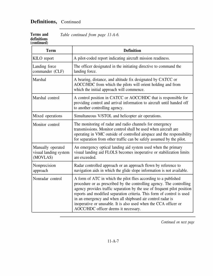
Definitions, Continued
Terms anddefinitions(continued)
Table continued from page 11-A-6.
Term
KILO report
Landing forcecommander (CLF)
Marshal
Marshal control
Mixed operations
Monitor control
Manually operatedvisual landing system(MOVLAS)
Nonprecisionapproach
Nonradar control
Definition
A pilot-coded report indicating aircraft mission readiness.
The officer designated in the initiating directive to command thelanding force.
A bearing, distance, and altitude fix designated by CATCC orAOCC/HDC from which the pilots will orient holding and fromwhich the initial approach will commence.
A control position in CATCC or AOCC/HDC that is responsible forproviding control and arrival information to aircraft until handed offto another controlling agency.
Simultaneous V/STOL and helicopter air operations.
The monitoring of radar and radio channels for emergencytransmissions. Monitor control shall be used when aircraft areoperating in VMC outside of controlled airspace and the responsibilityfor separation from other traffic can be safely assumed by the pilot.
An emergency optical landing aid system used when the primaryvisual landing aid FLOLS becomes inoperative or stabilization limitsare exceeded.
Radar controlled approach or an approach flown by reference tonavigation aids in which the glide slope information is not available.
A form of ATC in which the pilot flies according to a publishedprocedure or as prescribed by the controlling agency. The controllingagency provides traffic separation by the use of frequent pilot positionreports and modified separation criteria. This form of control is usedin an emergency and when all shipboard air control radar isinoperative or unusable. It is also used when the CCA officer orAOCC/HDC officer deems it necessary.
Continued on next page
11-A-7

Definitions, Continued
definitionsTerms and Table continued from page 11-A-7.
(continued)Term
Parrot
Pigeons
Platform
Popeye
Port holding pattern
Positive control(carrier)
Precision approach
Precision approachand landing system(PALS)
PALS acquisitionwindow
Definition
Military IFF/transponder.
Magnetic bearing and distance from an aircraft to a specific location.
A point of 5,000 feet altitude in the approach pattern at which all jetand turboprop aircraft decrease their rate of descent to not more than2,000 feet-per-minute and continue letdown to the 10-nm DME fix.
A pilot’s term used to indicate that his or her aircraft has enteredIMC.
The Case I jet and turboprop aircraft holding pattern is a left-hand,5-mile pattern tangent to the BRC (or expected BRC) with the shipin the 3 o’clock position of the holding pattern. The altitude isassigned via landing order as established in the ship and airwingdoctrine.
A form of air traffic control in which the controlling agency hasradar and radio contact with the aircraft that is being controlled, andpublished approach or departure procedures are complied with. Italso pertains to controllers who give specific headings and altitudesfor aircraft to fly. While the pilot provides altitude separation bymaintaining assigned altitudes, the air traffic controller isresponsible for lateral and time separation. The air traffic controllermay direct speed changes.
An approach in which the azimuth, glide slope, and distanceinformation are provided to the pilot.
A system that consists of shipboard and aircraft components for allweather recovery of carrier-based aircraft.
An area in space (normally 3.5 to 5 miles from touchdown point) inwhich PALS radar acquires an aircraft for final control.
Continued on next page
11-A-8

Definitions, Continued
Table continued from page 11-A-8.
(continued)
Terms anddefinitions
Term Definition
Primary flightcontrol (PriFly)
Ramp time (readydeck)
Six nautical mileDME fix (carrier)
Spin
Starboard holdingpattern (carrier)
Tactical air controlcenter (TACC)
Tactical direction
The position on the ship where the air officer or designatedrepresentative observes flight deck operations and provides visualcontrol to aircraft that operate in the carrier control zone.
Anticipated time specified by PriFly that the deck will be ready torecover aircraft and the first aircraft of a Case III recovery isexpected to be at the ramp.
A checkpoint on a CCA that is located on the final bearing 6 milesfrom the carrier through which all jet and turboprop aircraft willpass in level flight at an altitude of 1,200 feet in landingconfiguration. Turboprop aircraft may be instructed to pass throughthe 6-nm DME fix at 1,200 feet and commence transition to thelanding configuration.
A signal given to one or more aircraft that indicates a departurefrom and reentry into the break. The command “Spin” may beissued by either the air officer or the flight leader.
A right-hand racetrack pattern between 045° and 135° relative to theship for COD aircraft and 045° and 110° relative for helicopters.COD aircraft hold at 500 feet or 1,000 feet if approved by PriFly,and helicopters hold at 300 feet or below.
The primary air control agency within the amphibious objective areaof responsibility from which all air operations that support theamphibious force are controlled. This control refers to all airborneoperations not a part of the actual launch or recovery of aircraft.
A form of nonradar control where tactical information is passed toan aircraft by the controlling unit, but the aircraft commander isresponsible for navigation and safety.
Continued on next page
11-A-9

Definitions, Continued
Terms anddefiitions(continued)
Table continued from page 11-A-9.
Term Definition
Ten nautical mileDME fix (carrier)
Three nautical mileDME fix
V/STOL
Twelve nautical mileDME fix(amphibious)
A checkpoint on a CCA that is normally located on the finalbearing 10 miles from the carrier. All jet and turboprop aircraftwill pass through the 10-nm DME fix in level flight at an altitudeof 1,200 feet at 250 KIAS and will normally commence transitionto the landing configuration.
A checkpoint on a CCA that is located on the final bearing 3 milesfrom the ship through which all turboprops and helicopters willpass in a landing configuration.
An aircraft, other than a helicopter, whose flight characteristicsenable vertical and short takeoffs and landings.
A checkpoint on a CCA that is normally located on the final bearing12 miles from the ship. All V/STOL aircraft will pass through the12-nm DME fix in level flight at an altitude of 1,200 feet at 250KIAS and will normally commence transition to the landingconfiguration.
Continued on next page
11-A-10

Definitions, Continued
Table continued from page 11-A-10.
(continued)
Terms anddefinitions
Term Definition
Weather criteria(amphibious)
The following weather criteria applies to V/STOL aircraft:
Case I—Ceiling no lower than 3,000 feet and visibilitynot less than 5 nm.Case II—Ceiling no lower than 1,000 feet and visibilitynot less than 5 nm. These minimums can be lowered bythe ship's commanding officer for special operations.Case III—Ceiling below 1,000 feet or visibility less than5 nm. Case III is also used when the ceiling or visibilitydecreases to below those minimums established by theship's commanding officer for special operations.
The following weather criteria applies to helicopters:
Case I—Ceiling no lower than 1,000 feet and visibilitynot less than 3 nm.Case II—Ceiling no lower than 500 feet and visibility notless than 1 nm.Case III—Ceiling less than 500 feet or visibility less than1 nm.
Continued on next page
11-A-11

Definitions, Continued
Terms anddefinitions(continued)
Table continued from page 11-A-11.
Term Definition
Weather criteria(carrier)
ZIP LIP
The following weather criteria applies to carrier operations:
Case I—Ceiling no lower than 3,000 feet and visibilitynot less than 5 miles.Case II—Ceiling no lower than 1,000 feet and visibilitynot less than 5 miles.Case III—Ceiling below 1,000 feet or visibility less than 5miles.
Refer to CV NATOPS Manual, NAVAIR 00-80T-105, for helicopterweather criteria during carrier operations.
A condition that may be prescribed for flight operations duringdaylight VMC under which positive communications control iswaived. Radio transmissions between aircraft and between pilots andcontrol agencies are held to the minimum necessary for flight safety.
For carriers—COD aircraft are exempted from ZIP LIP unlessspecifically noted in Overhead Message.
For amphibious operations—ZIP LIP may be prescribed during nightVMC.
11-A-12

Section BCATCC Operating Positions
Overview
Introduction The Air Operations Officer is responsible to the Operations Officer for thecoordination of all matters pertaining to flight operations and for the properfunctioning of CATCC. CATCC is broken down into two branches—AirOps and CCA. Each of these branches is responsible for certain tasks whichare performed by personnel assigned to operating positions within therespective branches. When you are assigned to a carrier, you will have anopportunity to qualify on some, if not all, of the operating positions inCATCC. Remember, no one position is more important than the other; eachposition is vital to the overall CATCC team and its mission.
In this section This section consists of the following topics:
Topic See Page
Air Ops Operating Positions 11-B-2
CCA Operating Positions 11-B-5
11-B-1

Air Ops Operating Positions
Introduction The Air Ops branch of CATCC, sometimes referred to as the front room,performs many of the tasks required to ensure accurate and timelyinformation concerning aircraft operations is disseminated throughout theship. When you are assigned to Air Ops, you will be required to operate andqualify on different positions that gather and update critical flight operationsdata.
Operating The following table lists the Air Ops positions and some of their majorpositions duties:
Position
Air operations officer
Duties
Review air planSupervise and coordinate the execution of the air planEnsure all operational information required for aircraftoperations is forwarded to the appropriate personnelConduct air wing and squadron briefingsEnsure that records and reports of flight operations areprepared and maintainedReceive, respond to, and prepare all correspondencerelated to flight operations
Air operations watchofficer
Ensure prelaunch briefing information is timely andefficiently distributedProvide pertinent flight operations information and airplan changes to appropriate departments and personnelManage fuel assets, monitor tanking station assignments,and tanking proceduresRemain informed of the status of helicopters operatingwith the carrierAssist CDC and PriFly with SAR operations
Continued on next page
11-B-2

Air Ops Operating Positions, Continued
Operatingpositions(continued)
Table continued from page 11-B-2.
Position
Air Ops supervisor
Duties
Ensure assigned personnel are properly trained andqualifiedEnsure all status board information is accurate andcompleteEnsure CATCC equipment and systems are beingoperated per EMCON restrictionsEnsure master air plan is maintained and that changesand revisions are forwarded to the proper personnelEnsure prelaunch information is accurate and completeEnsure weather information for the ship and bingofields is updatedEnsure all alert condition information is posted andupdated as necessaryEnsure that the land/launch record is accurate andcompleteAt the completion of flight operations, ensure allreports are completed (e.g., master air plan,land/launch record, daily air operations summary, etc.)
Air Ops plotter Plot ship's positionDetermine the range and bearing to divert and bingofields and update appropriate status boards
Continued on next page
11-B-3

Air Ops Operating Positions, Continued
Operatingpositions(continued)
Table continued from page 11-B-3.
Position
Air Ops plotter(continued)
Land/Launch recorder
Duties
Depict the ship's position in relation to airways, hotareas, airspace boundaries, etc. on appropriate chartsPlace bingo fields and ship’s current weather on statusboardsPrepare and disseminate prelaunch briefing information
During flight operations, maintain the land/launchrecord by updating and revising such information as:
–event numbers–aircraft side numbers–pilot names–launch times–recovery times–aircraft mission–aircraft profiles
Status board keeper Maintain status boards with current event numbers, sidenumbers, and pilot namesDuring Case III operations, update aircraft lineupinformationRecord and update aircraft profiles (e.g., bolters, traps,waveoffs, etc.)Record aircraft launch and recovery timesRecord and update aircraft fuel statesWhen needed, coordinate information between PriFly,CDC, FDC, ready rooms, and CCA
Continued on next page
11-B-4

CCA Operating Positions
Introduction The controllers in CCA, sometimes referred to as the back room, update andchange aircraft data on status boards similar to the controllers in Air Ops;however, they also provide sequencing and separation to aircraft duringlaunches and recoveries.
As a CCA controller, you will be required to perform and qualify on controlpositions such as approach control, marshal control, and departure controland noncontrol positions such as approach status board keeper and VDBoperator.
Operatingpositions
The following table lists the CCA positions and some of their major duties:
Position
CCA officer
Duties
Prior to flight operations, identify any possible problemsthat may affect the launch and recovery of aircraftDetermine the instrument approach procedure andmarshal radial for Case II and III recoveriesBrief CCA personnel on all relevant information (e.g.,BRC, ramp time, airspace constraints, etc.) concerninglaunch and recovery operationsEnsure all aircraft conform to departure and recoveryprocedures and that sufficient separation is providedduring Case II and III operationsMonitor aircraft and tanker fuel statesCoordinate refueling operations with Air Ops anddeparture controlMake decisions concerning issuing a DELTAConduct air wing and squadron debriefings
Continued on next page
11-B-5

CCA Operating Positions, Continued
Operatingpositions(continued)
Table continued from page 11-B-5.
Position
CATCC supervisor
Duties
Assist the CCA officer in his or her dutiesAssign CCA personnel to flight operations positionsIdentify airspace constraints that may affect launch andrecovery operationsBrief and debrief the CCA team on flight operationsEnsure that CCA status boards are accurate and completeEnsure that CATCC equipment is functioning properlyand report discrepanciesSupervise CCA personnel and provide coordinationbetween the CCA team as neededMonitor aircraft fuel states and tanker operationsCoordinate actions to deal with aircraft emergencies, lowfuel states, and other aircraft problems with the CCAofficer
Approach control Maintain adequate separation and ensure safety of flightIdentify any airspace constraints that may affect recoveryoperationsEnsure approach status board is accurate and completeCoordinate with the CATCC supervisor for recoveryinformation such as type recovery, expected BRC, marshalradial, expected final bearing, etc.Provide positive control instructions to recovery and(during Case III) bolter aircraftCoordinate handoffs with the CATCC supervisor, marshalcontrol, departure control, final control, the other approachcontrolContinue to monitor aircraft after handoff to the finalcontroller to ensure sufficient separation is maintained
NOTE: Two approach control positions are normally mannedduring Case III operations
Continued on next page
11-B-6

CCA Operating Positions, Continued
Final control
Operatingpositions(continued)
Table continued from page 11-B-6.
Duties
Marshal control Provide marshal instructions including EATs torecovering aircraftMaintain adequate separation between aircraftIdentify airspace constraints that may affect recoveryoperationsCoordinate with the CATCC supervisor for recoveryinformation such as type recovery, expected BRC,marshal radial, etc.Ensure marshal status board is accurate and updated asnecessaryCoordinate handoffs with the CATCC supervisor,approach control, departure control, and any otherappropriate agenciesIssue speed adjustments and radar vectors to aircraftwhen necessaryMonitor fuel states of aircraft inbound to and establishedin marshalImplement DELTA procedures when directed
Maintain adequate separation and ensure safety of flightCoordinate with the CATCC supervisor for recoveryinformation such as type recovery, expected final bearing,bolter holes, etc.Coordinate handoffs with the CATCC supervisor,approach control, and the other final controllerProvide aircraft with precision and nonprecisionapproaches
NOTE: Two final control positions are normally manned duringCase III operations
Continued on next page
11-B-7
Position

CCA Operating Positions, Continued
Table continued from page 11-B-7.
(continued)
Operatingpositions
Position Duties
Departure control
Marshal status boardkeeper
Maintain adequate separation and ensure safety of flightReview the tanking planCoordinate with CATCC supervisor for type departure,BRC, and DRRPrior to launch, provide departing aircraft with anychanges in departure information such as mission, typedeparture, DRR, BRC, etc.If weather conditions warrant, provide positive controlto launching aircraftMonitor performance of departing aircraft until pilotsreport KILO or aircraft are handed off to anotheragencyCoordinate handoffs with CATCC supervisor, approachcontrol, CDC, and marshal controlMonitor tanker position, tanker refueling status, tankerfuel state and give, receiver aircraft position, and allother matters evolving around tanker operationsMaintain a count of aircraft launched and remaining tobe launchDuring Case III operations, conduct a communicationscheck with the plane guard helicopter at least every 20minutesProvide relevant launch and recovery information to theplane guard helicopter
Prior to the commencement of recovery operations,record pre-recovery information such as event number,type of recovery, expected final bearing, ramp time,aircraft side numbers, etc.Monitor the marshal frequency and obtain and recordpertinent marshal information (e.g., EAT, fuel state,emergency information, approach button, etc.)
Continued on next page
11-B-8

CCA Operating Positions, Continued
Operatingpositionscontinued)
Table continued from page 11-B-8.
Position Duties
Approach status boardkeeper
Departure status boardkeeper
Sound-powered phonetalker/VDB operator
Prior to the commencement of recovery operations, recordpre-recovery information such as type of recovery,expected final bearing, BRC, ramp time, aircraft sidenumbers, etc.Monitor approach/final frequencies and record anychanges such as aircraft profiles, fuel states, approachstatus, etc.
Prior to the commencement of launch operations, recordprelaunch information such as event number, type oflaunch, expected DRR, BRC, ship’s weather, aircraft sidenumbers, etc.Monitor departure frequency and record departureinformation such as launch times, aircraft profiles, tankerstatus, fuel states, planeguard communication checks, etc.Coordinate with the departure controller to maintain anaccurate and complete account of launch operations
Monitor approach and final control to obtain aircraftrecovery orderMaintain an accurate account of aircraft recovery orderand position on the VDBProvide LSO and PriFly with aircraft recovery order andapproach/final button (frequency)Obtain Mode I wire engagement information
11-B-9


O v e r v i e w
Section CCATCC Control Criteria
Introduction On a carrier, the time it takes to launch and recover aircraft is critical tomission readiness. These operations must be completed quickly and safely todeter any potential threat. Therefore, different types of control proceduresand reduced separation standards are applied during shipboard operations.As a controller at sea, you must be thoroughly familiar with these controlprocedures and reduced separation standards and be able to apply themduring aircraft launches and recoveries.
In this section This section consists of the following topics:
Topic See Page
Control Procedures 11-C-2
Separation Criteria 11-C-6
11-C-1
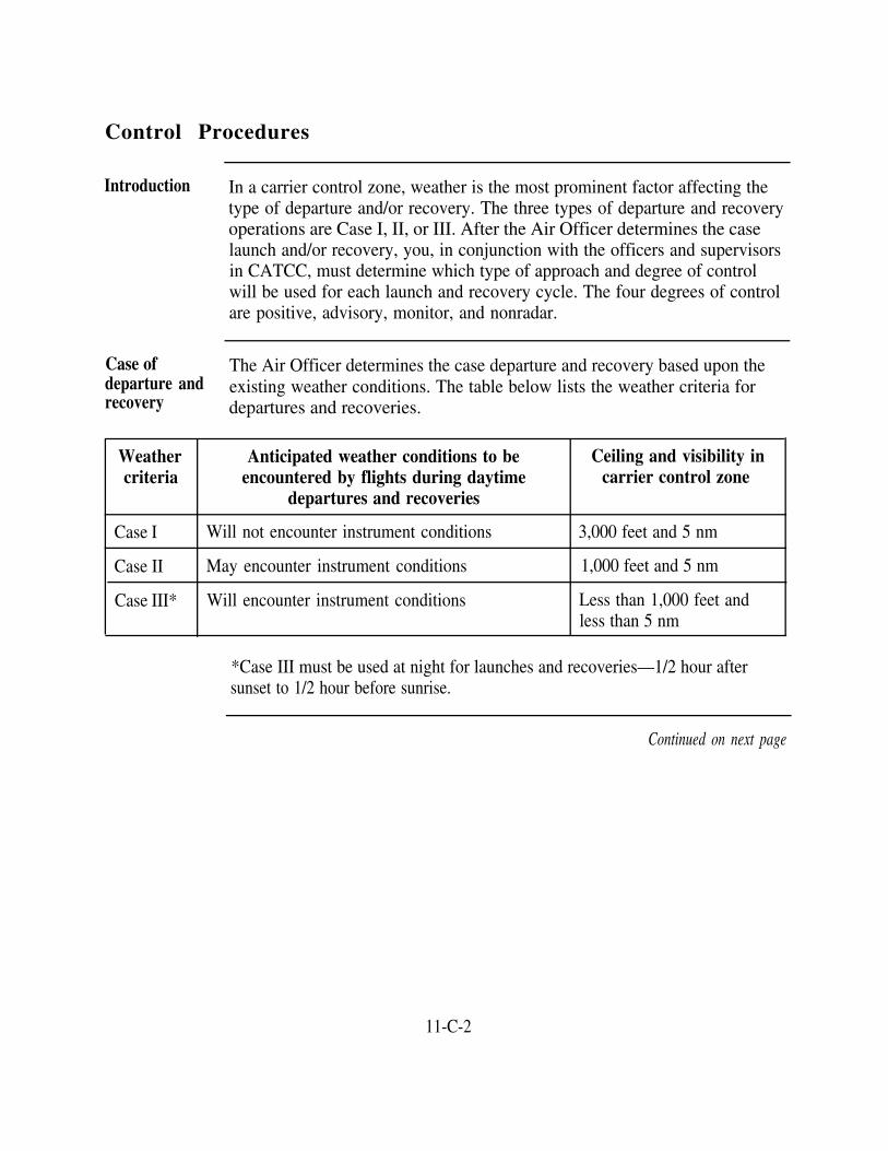
Control Procedures
Introduction In a carrier control zone, weather is the most prominent factor affecting thetype of departure and/or recovery. The three types of departure and recoveryoperations are Case I, II, or III. After the Air Officer determines the caselaunch and/or recovery, you, in conjunction with the officers and supervisorsin CATCC, must determine which type of approach and degree of controlwill be used for each launch and recovery cycle. The four degrees of controlare positive, advisory, monitor, and nonradar.
Case of The Air Officer determines the case departure and recovery based upon thedeparture and existing weather conditions. The table below lists the weather criteria forrecovery departures and recoveries.
Weathercriteria
Anticipated weather conditions to be Ceiling and visibility inencountered by flights during daytime carrier control zone
departures and recoveries
Case I Will not encounter instrument conditions 3,000 feet and 5 nm
Case II May encounter instrument conditions 1,000 feet and 5 nm
Case III* Will encounter instrument conditions Less than 1,000 feet andless than 5 nm
*Case III must be used at night for launches and recoveries—1/2 hour aftersunset to 1/2 hour before sunrise.
Continued on next page
11-C-2

Control Procedures, Continued
Departure and The following tables provide the restrictions that apply to different departuresrecovery and recoveries:restrictions
If the recovery is: The departure can be:
Case I
Case II
Case I or II only
Case I or II only
Case III Case I, II, or III
If the departure is: The recovery can be:
Case I Case I, II, or III
Case II Case I, II, or III
Case III Case III only
Positive control Positive control is a form of air traffic control in which the controllingagency has radar and radio contact with the aircraft being controlled. Also,the published approach or departure procedures are being complied with, orthe specific assignments regarding heading and altitude are being issued bythe controller. Vertical separation is provided by requiring pilots to maintainassigned altitudes or flight levels. Lateral and time separation is theresponsibility of the controller. Speed changes may also be directed by thecontroller.
Positive control must be used in any of the following conditions:
Ceilings of less than 1,000 feet for fixed-wing operations and lessthan 500 feet for helicoptersForward flight visibility of less than 5 miles for fixed-wing operationsor 1 mile or less for helicopters
Continued on next page
11-C-3

Control Procedures, Continued
Positive control Whenever flight operations are conducted between 1/2 hour aftersunset and 1/2 hour before sunrise except as modified by the OTC orthe carrier commanding officerDuring mandatory letdown in thunderstorm areasIn any other situation where supervisory personnel can anticipateweather phenomena that might cause difficulty to pilots
(continued)
Advisorycontrol
Monitor control
Nonradarcontrol
Advisory control is a form of control in which the controlling agencymaintains radio and radar contact with aircraft under its control and providestraffic advisories. The pilot maintains traffic separation with the assistance ofthe controlling agency.
Advisory control must be used when the traffic density in an operating arearequires a higher degree of control for the safety of flight than is providedunder VFR.
Normally, advisory control is limited to the following situations:
VMCFor all operations in or adjacent to oceanic control areas or routes
Monitor control is the monitoring of radar and radio channels for emergencytransmissions.
Monitor control must only be used when the following conditions exist:
Aircraft are operating in VMC,Aircraft are operating outside controlled airspace, andSeparation from other traffic can be safely assumed by the pilot
Nonradar control must be used when the shipboard radar cannot be used bycontrollers to provide radar separation under conditions that normally requirepositive control procedures. The radar may be inoperative or degraded to thepoint where it is unusable.
Continued on next page
11-C-4

Control Procedures, Continued
Nonradarcontrol(continued)
The decision to use nonradar control at night or in IMC must be made withcareful consideration of factors such as
Actual meteorological conditionsDegree of radar degradationExpected duration of radar degradationFuel states and tanker fuel available for delaysDivert field conditionsOperational requirementsDeparture or recovery in progressAvailability of other surface or airborne platforms to provide radarseparation and approach information
NOTE: The carrier air operations manual shall include procedures usedduring shipboard systems failures.
11-C-5

Separation Criteria
Introduction At sea, you will be expected to separate, sequence, and vector aircraft fasterand closer than in any other air traffic control environment. To accomplishthis task, you must know the lateral and vertical separation criteriaestablished on carriers for use in positive control situations. Theserestrictions do not apply to tactical maneuvers such as air intercept andrendezvous.
Lateralseparation
The following lateral separation is used when aircraft are controlled oncarriers:
Degree of control Aircraft operating situation Minimum lateralseparation required
Positive control bydesignated air search radarthat rotates in excess of 7rpm
50 miles or more from monitoringantenna
Less than 50 miles from monitoringantenna
5 miles
3 miles
On a designated approach or 2 milesestablished downwind and inside 10miles of the ship
Established on final approach within 5 1 1/2 milesmiles of the ship
Positive control by otherthan designated air searchradar
All situations 5 miles
Nonradar control Using a published approach 2 minutesor
5 miles DME
Continued on next page
11-C-6

Separation Criteria, Continued
Verticalseparation
The following vertical separation is used when aircraft are controlled oncarriers:
Jet and turbopropeller (turboprop) aircraft:
Altitude Minimum required vertical separation
Up to and includingFL 290
1,000 feet (may be reduced to 800 feet when theaircraft is within 10 miles of the ship)
Above FL 290 2,000 feet
NOTE: Carrier-based aircraft must fly MSL altitudes below 18,000 feetMSL and flight levels at and above 18,000 feet MSL unless regionalsupplementary procedures as published in FLIP planning dictate otherwise.
Helicopters must be separated by 500 feet.
11-C-7


Overview
Section DCATCC Departure Procedures
Introduction One of the first essential phases of carrier operations is to get the aircraftairborne and safely on their missions. As a departure controller, you will beresponsible for the initial separation of aircraft until handed off to CDC orthe pilot is ready to proceed on his or her mission (KILO). Also, you will bedirectly involved in tanker operations.
In this section This section consists of the following topics:
Departure Radials
Topic See Page
11-D-2
Departure Voice Reports 11-D-5
Departures and Rendezvous 11-D-6
11-D-1

Departure Radials
Introduction
departure control, you must have a thorough understanding of how theseradials are used by each squadron.
During Case II and III departures, one of the means used to provide initialseparation of airborne aircraft is the use of departure radials. When working
Assignment of Departure procedures are based upon the assignment of TACAN radials todeparture provide for lateral separation. These radials are assigned to squadrons by theradials air wing and published in carrier air operations manual or air wing doctrine.
The minimum standard separation of departure radials is 20°. Normally, alldepartures are conducted under advisory control with a transition to positivecontrol when necessary, for example, weather, emergencies, pilot request,and so forth.
You normally assign departure radials dependent on the following:
Mission of the aircraftNumber of carriers in the formationTopographical features in the areaThose radials reserved for emergencies, letdowns, or helicopterholding
Continued on next page
11-D-2

Departure Radials, Continued
Departure fanand departurereference radial(DRR)
assigned by CATCC to which all squadron departure radials are based-theDRR. A departure fan is displayed below.
The departure fan displays the radials assigned to each squadron as publishedin the carrier or air wing doctrine. The fan is based on a TACAN radial
NOTE: The DRR is provided as part of the prelaunch briefing 2 1/2 hoursprior to each event. Although the DRR is normally the same as the expectedBRC, the conditions listed in the previous section may cause the DRR to bedifferent than the actual BRC.
Continued on next page
11-D-3

Departure Radials, Continued
Departure fan To accommodate the differences that can occur in the DRR betweenand departure departures, the air wing assigns departure radials to squadrons in 20 degreereference radial(DRR)
increments. For example, squadron A is assigned a departure radial of minus
(continued) 40 degrees, squadron B a departure radial of minus 20, and squadron C thesame as the DRR. Pilots determine their actual departure radial for eachlaunch by adding or subtracting their squadron’s assigned departure radialfrom the DRR. If the DRR is 320 degrees, the actual departure radials forsquadrons A, B, and C would be 280, 300, and 320 degrees, respectively.
Squadron
A
B
C
D
E
F
G
H
Assigned DepartureRadial
-40
-20
DRR
+20
+40
+60
+80
+100
Rendezvous altitude
Odd
Even
Odd
Even
Odd
Even
Odd
Even
11-D-4

Departure Voice Reports
Introduction During a launch, you can get pretty busy as a departure controller. To assistyou in identifying and tracking departing aircraft, specific voice reports havebeen established.
Voice reports The following table lists the standard departure voice reports common foreach particular case of departure:
Report Case II Case III
AIRBORNE
PASSINGANGELS TWOPOINT FIVE
X X
X X
ARCING X X
EstablishedOUTBOUND
IMC (POPEYE)with altitude
X X
X X
X X
X X
ON TOP withaltitude
MissionReadiness(KILO)
Two of the above voice reports that are not self-explanatory are POPEYEand KILO. POPEYE is a report that indicates that an aircraft is in IMC andis awaiting further instructions. This is the only mandatory pilot voicereport. KILO indicates that an aircraft is ready to proceed on its mission.
11-D-5

Departures and Rendezvous
Introduction During launches, fixed-wing aircraft and helicopters have certain departureprocedures to follow. Also, rendezvous guidelines are established for fixed-wing aircraft. Weather is one of the primary factors that determines whichdeparture and rendezvous procedure will be used. Additionally, performancecharacteristics dictate the initial climbout instructions for certain aircraft.
Departure The following table lists the departure procedures used in each case ofprocedures departure:
Weather Criteria Jet Turboprop Helicopter
Case I After a clearing turn, Same as jet. Depart as directed byproceed straight the tower.ahead paralleling theBRC at 500 feet until7 nm. Then, clearedto climb unrestrictedin VMC.
Case II After a clearing turn, After a clearing turn, Depart as directed byproceed straight parallel the BRC at the tower.ahead at 500 feet 500 feet. At 6 nm,paralleling the BRC. turn to intercept theAt 7 nm, turn to 7-nm arc maintainingintercept the 10-nm VMC untilarc and maintain established on theVMC until departure radial.established on the Maintain 500 feetdeparture radial. If until 12 nm on thethe aircraft can departure radial.maintain VMC, the500-foot restriction islifted after 7 nm. Jetsmust maintain 300knots until VMC ontop.
Continued on next page
11-D-6

Departures and Rendezvous, Continued
Table continued from page 11-D-6.
(continued)
Departureprocedures
Weather Criteria
Case III
Jet
Climb straight aheadaccelerating at 300knots crossing 5 nmat 1,500 feet orabove. At 7 nm,execute a turn to flythe 10-nm arc untilintercepting thedeparture radial.
Turboprop Helicopters
Climb straight aheadto 1,000 feetaccelerating to 250knots after levelingoff. At 5 nm, turn tointercept the 7-nmarc and arc tointercept thedeparture radial.Maintain 1,000 feetuntil 12 nm on thedeparture radial.
Climb straight aheadto 300 feet and arcwithin 3 miles of theship to intercept theassigned departureradial.
Rendezvousprocedures
Different rendezvous are dictated based on the case departure used.
Case I—Jet and turboprop aircraft must rendezvous by following airwing doctrine.Case II or III—Jet and turboprop aircraft must rendezvous between 20and 50 miles from the ship on the left side of the departure radial at aprebriefed altitude.
11-D-7


O v e r v i e w
Introduction
Section ECATCC Arrival Procedures
The recovery phase of carrier operations is fast-paced and challenging.Inbound aircraft must wait for aircraft to launch from the ship and for the ship'sdeck to become ready before they can land. Time and aircraft fuel statesbecome very important. However, the whole recovery evolution is a smoothlysynchronized event that is accomplished effectively by the various divisions ona ship.
In this section This section consists of the following topics:
Marshal Procedures
Approach Procedures
PALS Approaches
DELTA Procedures
Topic See Page
11-E-2
11-E-7
11-E-10
11-E-14
11-E-1

Marshal Procedures
Introduction Aircraft inbound to a carrier will call CATCC directly, or CATCC will receivea handoff from another agency such as CDC. Then, depending on the case ofrecovery, aircraft will either proceed directly to the ship or be given marshalinstructions. As a marshal controller, you provide pertinent recoveryinformation to inbound aircraft and establish the initial sequencing andseparation of aircraft.
Transfer of During Case II and III recovery operations, inbound flights that enter the carrierflights to control area (50-mile radius) are normally turned over to marshal control formarshal control further clearance to the marshal pattern. Positive radar identification should be(Case II andIII) accomplished by the marshal controller before the transfer of control. Control
may be transferred only after the marshal controller has notified the transferringcontroller that positive radar contact exists. Transient helicopters approachingthe carrier for landing must contact marshal control when they are at least 25miles out.
During Case II and III recovery operations, aircraft that were unable to check inwith the strike, mission, or marshal control because of communicationsdifficulties should proceed inbound to the emergency marshal at the briefedholding altitude.
Aircraftrecoveryinformation
The flight leader should provide you, the marshal controller, with the followinginformation:
Call signPositionAltitudeLowest fuel state in flight (in hours and minutes for helicopters and poundsfor fixed-wing aircraft)Total number of aircraft in flight (line-up)Type PALS approach requested—if applicable (UTMs sweet orsour—being received or not)Other pertinent information, such as navigational aid status, ordnance status,weather, etc., that may affect the recovery of aircraft
Continued on next page
11-E-2

Marshal Procedures, Continued
Marshalrecoveryinformation
As the marshal controller, you should provide an inbound flight with thefollowing information for a Case III recovery:
Case recoveryType of approachExpected FBAltimeter settingMarshal instructionsEATExpected approach buttonTime checkVector to marshal (if required)Multiple marshal stack information (radials/altitudes)
Marshalpattern andmarshal fix
During Case I recoveries, aircraft proceed directly to the carrier, and CATCCswitches the aircraft to PriFly's frequency when the pilot reports the ship insight. However, during Case II and III recoveries, aircraft must be placed in aholding pattern. This pattern is called a marshal pattern and is based on aTACAN marshal fix.
A primary TACAN marshal fix is normally established on a predeterminedradial at a distance appropriate for the type of aircraft; for example, jet,turboprop, or helo. The radial is established with reference to the expectedFB. The FB is the extended-landing-area centerline. The marshal fix issimilar to the IAF on an instrument approach to a naval air station.
Continued on next page
11-E-3

Marshal Procedures, Continued
Jet/Turboprop For jet and turboprop aircraft, the primary TACAN marshal fix is normallymarshal on the 180° radial relative to the expected FB at a distance of 21 miles plus 1
mile for every 1,000 feet of altitude. The base altitude will be as assignedbut not lower than 6,000 feet. The holding pattern is a left-hand 6-minuteracetrack pattern. The inbound leg must pass over the holding fix. Thefollowing table lists the altitudes and DME for a standard CV-1 marshalpattern:
Altitude Assignment(in feet)
Distance of Aircraft
6,000
Case II Case III
21 DME
7,000 22 DME 22 DME
8,000 23 DME
9,000 24 DME 24 DME
10,000 25 DME
11,000 26 DME 26 DME
12,000 27 DME
13,000 28 DME 28 DME
14,000 29 DME
15,000 30 DME 30 DME
16,000 31 DME
17,000 32 DME 32 DME
18,000 33 DME
19,000 34 DME 34 DME
Continued on next page
11-E-4

Marshal Procedures, Continued
Jet/Turboprop During Case II recoveries, an altitude block is left vacant in case the aircraftmarshal do not get the ship in sight by 5 miles. In this situation, the recovery would(continued) shift to a Case III recovery, and a vacant altitude is available to split up
aircraft flights into single aircraft at each altitude.
Helicoptermarshal
The primary TACAN marshal for helicopters is the 110° radial relative tothe expected FB at a distance of 1 mile for every 500 feet of altitude startingat 1,000 feet and 5 miles. The holding pattern is a right-hand racetrackpattern with 2-nm legs. The inbound leg must pass over the holding fix.
Emergencymarshal
Fixed-wing aircraft are issued an emergency marshal radial before launchshould radio failure occur. Normally the emergency marshal radial is 150°relative to the expected FB at a distance of 15 miles plus 1 mile for every1,000 feet of altitude (Angels + 15). For example, an aircraft that will hold at14,000 feet would be assigned 29 DME.
Jet/turboprop aircraft must not be assigned an altitude below 6,000 feet. Theholding sequence is jets first and turboprops second. The holding pattern is aright-hand 6-minute racetrack pattern with an inbound leg that passes overthe holding fix.
The helicopter emergency marshal radial is the same as the normal helicoptermarshal radial with emergency holding normally commencing at 7 miles.
Overheadmarshal
An overhead marshal should be used when geographical considerations oroperational circumstances dictate. The assigned inbound magnetic heading tothe holding fix should coincide with the outbound magnetic radial of theapproach. If overhead marshal is used as the emergency marshal fix, EEATsfrom the overhead marshal should be every other minute.
En route radar When an aircraft or flight cannot reach the assigned marshal point in time toapproach make an assigned approach time, because of mission, fuel state, or ordnance(random) load, you may have to use radar vectors to place the flight in the proper
approach sequence. Positive radar control is required. Whenever possible,you should provide the pilot with a brief description of the intendedpenetration.
Continued on next page
11-E-5

Marshal Procedures, Continued
Marshal You should make every effort to anticipate the weather conditions andaltitude provide marshaling in visual conditions, if practical. Aircraft below anassignment andseparation
overcast cloud layer should not be required to climb into the overcast tocomply with the marshal altitude limits if the marshal controller can maintainthe interval and sequence from the lower altitude. Aircraft above an overcastcloud layer should be assigned altitudes above the overcast and be retained information where possible.
You should limit formation flights to a maximum of four aircraft at any oneassigned altitude. Under instrument conditions, a section of two aircraft isthe maximum number authorized in any one flight and hence at the samemarshal altitude.
Normally, you should assign fixed-wing aircraft marshal altitudes thatprovide a 1,000-foot vertical separation. Helicopters are assigned altitudes atmarshal that provide a 500-foot vertical separation.
NOTE: When the flights of two aircraft are held at marshal duringinstrument conditions, it is advisable to provide vertical separation of 2,000feet between flights. This procedure makes sure that you can provide therequired 1,000 feet of vertical separation if a flight must be split.
11-E-6

Approach Procedures
Introduction Different types of approaches have been developed for carriers based onaircraft performance characteristics and the location from which aninstrument approach will commence. As a shipboard controller, you musthave a comprehensive knowledge of these approaches so you know whatactions a pilot will take when he or she makes an approach.
Approachweatherminimums
The commanding officer of a carrier can modify the approach weatherminimums for his or her ship. Certain situations such as the decreasedproficiency of a CATCC team or an embarked air wing can dictate a changein these minimums. However, the following table lists the absoluteminimums authorized for carrier instrument approaches:
Aircraft Type
Jet
Turboprop
Type of Approach Weather Minimums(ceiling and visibility)
Nonprecision 600 feet and 1 1/4 miles
ICLS 300 feet and 3/4 mile
ICLS/ILM with 200 feet and 1/2 mileSPN-42 or SPN-46monitor
Mode I As certified
Mode IA, II, IIT, III 200 feet and 1/2 mile
Nonprecision 400 feet and 1 mile
ICLS 300 feet and 3/4 mile
ICLS/ILM with 200 feet and 1/2 mileSPN-42 or SPN-46monitor
Mode II, IIT, III 200 feet and 1/2 mile
Helicopter Nonprecision
Mode III
300 feet and 3/4 mile
200 feet and 1/2 mile
Continued on next page
11-E-7

Approach Procedures, Continued
Approachweatherminimums(continued)
NOTE: PALS Mode I qualified aircraft without an operating ILM may becertified to minimums of 200-foot ceiling and 1/2-nm visibility.
PALS Mode I qualified aircraft with an operating ILM display may becertified to minimums less than 200-foot ceiling and 1/2-nm visibility.
Type ofapproach
One of the controlling factors that determines where a marshal pattern will belocated is the type of approach. The following table lists the different typesof approaches available:
Type of approach Type of aircraft Type of procedure
CV-1 Jet & Turboprop Straight-in
CV-2
CV-3
Jet & Turboprop
Helicopter
Overhead
Offset
Continued on next page
11-E-8

Approach Procedures, Continued
Type ofapproach(continued)
A CV-1 approach is displayed below.
11-E-9

PALS Approaches
Introduction One of the most critical phases of an instrument approach is the finalapproach segment. As a final controller on a carrier, you will use PALSequipment to provide control and guidance information to landing aircraft.The mode of approach determines what information you will give a pilot.Both precision and nonprecision approaches are available.
Precision final Jet and turboprop aircraft pass through the 6-mile DME fix at 1,200 feet atapproaches 150 knots in landing configuration and commence slowing to final-approach
speed. Unless otherwise directed by the final controller, the altitude of 1,200feet is maintained at approach speed until the glide path is intercepted(approximately 3 miles dependent upon the glide slope angle).
Helicopters pass through the 3-mile DME fix at 500 feet in landingconfiguration. They maintain 500 feet until interception of the glide path oruntil otherwise directed by the final controller.
PALS modes of PALS approaches differ by the type of control given (automatic or manual)aircraft control and how the information is relayed (display or voice). The following table
lists the different modes of PALS approaches and their type of control:
PALS Mode
Mode I
Mode IA
Mode II
Mode IIT
Type of Control
Fully automatic approach totouchdown
Automatic approach to 1/2 mile
Manual approach with PALS glideslope and lineup error informationprovided to the pilot by cockpitdisplay
Manual approach with controlinformation provided by both displayand voice (final controller)
Continued on next page
11-E-10

PALS Approaches, Continued
PALS modes of Table continued from page 11-E-10.aircraft control(continued)
PALS Mode Type of Control
Mode III Manual approach with informationprovided by the final controller
Mode Iapproach
A Mode I approach is a fully automatic approach to touchdown. At the6-mile DME fix, the pilot should engage the APC and AFCS. Normally atbetween 4 and 8 miles, the pilot receives via data link a LANDING CHECKdiscrete signal to indicate positive data link communications between theaircraft and the ship.
The controller acquires the aircraft between 3.5 and 8 miles, and theREADY/LOCKON discrete light illuminates. At that time, the controllermust report lockon with range, verify needles, and issue instructions asnecessary for the aircraft to intercept the centerline, and instruct the pilot toreport coupled. For example: "201 lockon, 5 miles, right ten, say needles."
Needles must be verified before the "Report Coupled" instructions are givenby the final controller. With the aircraft in straight and level flight, within10 knots of approach speed, and with a fly-up indication on his or her glideslope indicator, the pilot should engage autopilot coupler and report"Coupled."
If the aircraft is unable to couple, the controller should continue with a ModeII or III approach.
The controller must report sending commands. The illumination of theCOMMAND CONTROL discrete light indicates that the aircraft is receivingcommand signals via data link. The pilot must acknowledge receipt of datalink commands by reporting "Command control." Thirty seconds of coupledflight is desired prior to intercepting the glide path.
Continued on next page
11-E-11

PALS Approaches, Continued
Mode Iapproach(continued)
The controller should advise the pilot when he or she is approaching glidepath and may advise him or her of range each mile. The controller mustadvise the pilot at minimums unless the LSO has previously assumedresponsibility. The pilot responds with a ball report and includes the word"Coupled." For example: "201 Hornet ball, five point three coupled."
Mode IAapproach
A Mode IA approach is automatic to approach minimums with manualtakeover to touchdown. Mode IA approaches are conducted the same asMode I approaches except the pilot uncouples at or before reaching theapproach minimums and reports "Uncoupled." If the pilot uncouples at theball call, he or she includes the word "Uncoupling" in the ball report. Forexample: "201 uncoupling, Hornet ball, five point three, manual/auto."When the pilot reports uncoupling, the controller must downgrade the PALSto Mode II.
Mode IIapproach
A Mode II approach is a manual approach by the use of ILS-type (crossedneedles) instrument presentation. Mode II approaches are conducted thesame as Mode I/IA until receipt of the READY/LOCKON discrete light.
Then the controller must report lockon with range, verify needlepresentation, and issue instructions to intercept the centerline. For example:"201 lockon, 5 miles, right ten, say needles." The pilot must report needleposition. For example: "201 needles up and right." The controller mustconcur or downgrade the approach to Mode III and advise the pilot. Forexample: "201, concur" or "201, disregard needles, downgrade to ModeIII."
The controller must monitor the approach, advise the pilot when approachingthe glide path, and should inform him or her of the range at each mile. Thecontroller must advise the pilot when at minimums unless the ESO haspreviously assumed responsibility. The pilot responds with a ball report.
Mode IITapproach
A Mode IIT approach is a manual approach using needles instrumentpresentation with Mode III information. This is a training approach used tobuild pilot confidence in Mode II approaches.
Continued on next page
11-E-12

PALS Approaches, Continued
Mode IIIapproach
Nonprecisionapproach
ICLS approach
Helicopterrecoveries
A Mode III approach is a CCA talk-down approach with no requirement forspecial aircraft configuration. The controller must advise the pilot when theaircraft is at minimums unless the LSO has previously assumedresponsibility.
A nonprecision approach is conducted when a precision radar approach orsuitable visual landing aids are not available. An aircraft on final approachcontinues its descent to 600 feet after passing the (6-mile DME fix. As thefinal controller, you must provide sufficient information to the pilot tomaintain an accurate azimuth and altitude until reaching nonprecisionminimums.
The ICLS, or bullseye, is an ILS-type of system that uses the ILM andTACAN/DME. It provides the same type of information that PALSprovides; however, CATCC receives no visual indication on the type ofinformation sent to the aircraft. A pilot can also use the ICLS for twoadditional purposes.
To aid in positioning the aircraft for PALS radar acquisitionAs an independent monitor of aircraft approach performance during aPALS approach
Normally, a carrier recovers helicopters after it recovers all fixed-wingaircraft. When helicopters finish night plane guard duties, CATCC providesthe helicopters with the positioning information they need to quickly interceptthe glide path and land.
During IMC recoveries, the pilot must fly a Mode III approach until he orshe acquires visual contact with the optical landing aids. At which time he orshe must report "Ball." Control is then assumed by the air officer, whoissues final landing clearance. If a waveoff occurs, the pilot must parallel theFB course and report to CATCC for control.
11-E-13

DELTA Procedures
Introduction Sometimes, it is necessary to delay a recovery because the ship's deck is notready for the landing of aircraft due to such things as an emergency or thelaunch not being complete. In these type situations, the CCA officer orCATCC supervisor may direct the marshal controller to issue a signalDELTA to inbound and holding aircraft.
DELTAresponsibilities
During Case I flight operations, PriFly gives the DELTA signal to recoveringaircraft when necessary. During Case II or III flight operations, CATCCissues DELTA signals as required.
DELTA signalcomposition
The DELTA signal consists of the word DELTA and a number suffixindicating the number of minutes that the recovery is expected to be delayed.DELTA delays are always given in even numbers and never given for lessthan four minutes. For example, if a 6 minute delay is necessary, themarshal controller would issue a DELTA SIX.
Aircraft actions An aircraft's position at the time a DELTA is issued determines what actionsa pilot will take.
Aircraft in the marshal pattern remain in the holding pattern and awaitthe assignment of a new EAT.Aircraft that have already commenced an approach but are above7,000 feet level off at the next lower odd altitude and hold on the inboundbearing at a range in nm equal to the holding altitude in thousands of feetplus 15 (angels + 15). The aircraft hold by using a 6-minute racetrackpattern and await assignment of a new EAT. Aircraft that have re-enteredholding at the next odd altitude must report when they are established inholding with the new altitude.Aircraft that have already commenced an approach but are at orbelow 7,000 feet continue the approach and await further instructions.
All aircraft are required to acknowledge the receipt of new EATs.
11-E-14

Overview
Introduction
In this section
Section FTanker Operations
Tanking (aerial refueling) is an important aspect of carrier operations. Inmany cases, aircraft on or returning from a mission require additional fuel toreturn and land safely on a carrier. Also, having sufficient fuel becomescritical when the only available landing area is the ship itself because asuitable land base is outside the flying range of an aircraft. As a departurecontroller, you will be actively involved in tanker operations and monitoringfuel states.
This section consists of the following topics:
Topic See Page
General Tanking Procedures 11-F-2
Tanking Terms 11-F-3
Tanker Patterns 11-F-4
11-F-1

General Tanking Procedures
Introduction Tanker aircraft are assigned duties in support of the recovery of aircraft.Normally, a tanker that has just been launched becomes the duty tanker forthe recovery that follows immediately provided that the tanker's store isoperational. Those tankers that are known to have a good store and sufficientfuel to meet receiver requirements display a flashing green light.
Tanker control A specific agency (normally departure control) is designated as tankerresponsibilities control. Tanker control monitors the following:
Coordination of the tanker and receiver rendezvous
Tanker give-away fuelTanker locationLocation and fuel requirements of the low fuel state aircraft (low-stateaircraft)
11-F-2

Tanking Terms
Introduction To understand tanker operations, you must know the meaning of certaintanking terms. You will use these terms as a departure controller to relaytanking information.
Terms and The following table contains commonly used tanking terms and theirtheir meanings meanings:
Term
Give
Hawk
Package
Plugged andReceiving
Sour
State
Sweet
Trick or Treat
Meaning
The amount of fuel the tanker has to transfer to other aircraft.
An order given to a tanker pilot to visually acquire a low-stateaircraft that is on approach to the ship and position the tanker torendezvous immediately with the aircraft if it bolters or waves off.
A tanker's refueling system.
The refueling probe is in the drogue of the tanker's refueling hoseand properly taking on fuel.
A tanker's fuel package will not transfer.
Same as fuel state. The amount of fuel of an aircraft expressed inpounds for fixed-wing aircraft and hours and minutes forhelicopters.
The refueling system is functioning properly.
An instruction issued to the tanker pilot that advises him or her thata particular aircraft requires fuel if it bolters. Normally, the numberof pounds required to transfer accompanies the instruction, forexample, "trick or treat for two."
11-F-3

Tanker Patterns
Introduction Certain factors determine the altitude and type of pattern a tanker aircraft isrequired to fly. As a departure controller, you must know these factors andthe patterns that will be flown.
VMCrendezvouscircle
After an oncoming tanker's package checks sweet, it will enter a rendezvouscircle pattern oriented on the carrier. The pattern has four reference points.The tanker pilot and the departure controller use these points to indicate theposition of the tanker in relation to a potential receiving aircraft.
Continued on next page
11-F-4
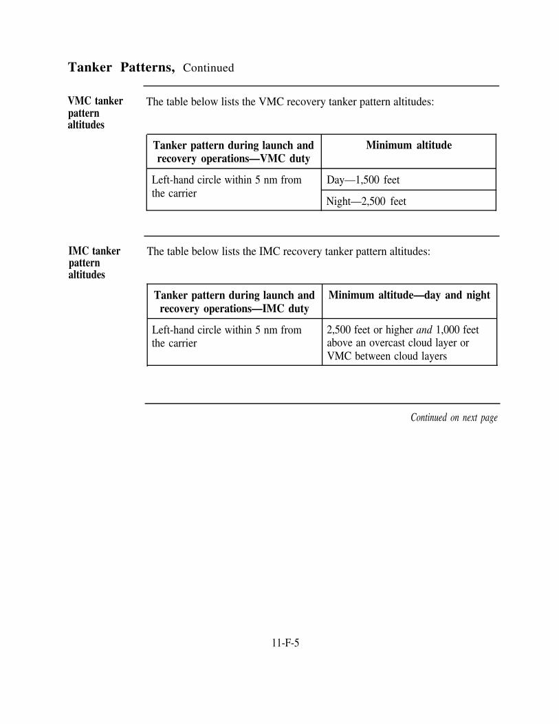
Tanker Patterns, Continued
VMC tankerpatternaltitudes
The table below lists the VMC recovery tanker pattern altitudes:
Tanker pattern during launch andrecovery operations—VMC duty
Minimum altitude
Left-hand circle within 5 nm fromthe carrier
Day—1,500 feet
Night—2,500 feet
IMC tankerpatternaltitudes
The table below lists the IMC recovery tanker pattern altitudes:
Tanker pattern during launch and Minimum altitude—day and nightrecovery operations—IMC duty
Left-hand circle within 5 nm from 2,500 feet or higher and 1,000 feetthe carrier above an overcast cloud layer or
VMC between cloud layers
Continued on next page
11-F-5

Tanker Patterns, Continued
Rendezvous low If the tanker is instructed to hawk a low fuel state aircraft, the tanker pilotpattern must adjust the tanker pattern. The pilot must position the tanker so that the
tanker aircraft is at the 2 o'clock position of the hawked aircraft if and whenthe hawked aircraft bolters/waves-off. This pattern adjustment places thetanker in an easily accessible acquisition position for the hawked aircraft.The minimum altitude for the rendezvous low pattern is 1,500 feet during theday and 2,500 feet at night.
Continued on next page
11-F-6

Tanker Patterns, Continued
Receiverengagedpattern
Once the hawked aircraft, now called receiving aircraft, successfully engagesthe tanker's refueling probe, the tanker establishes itself and the receivingaircraft in a racetrack pattern in the vicinity of the ship. Normally, thetanker should not proceed more than 10 nm ahead of the ship. Thedownwind leg of the pattern should be 3 to 5 miles abeam the ship, and thetanking evolution should be completed before the tanker and receivingaircraft reach a point 6 miles astern the carrier. The 6-mile-astern positionplaces the receiving aircraft in the proper position to reenter the CCArecovery pattern.
11-F-7


Overview
Section GAmphibious ATC Scope
Introduction On an LHA or LHD, a majority of the duties performed by air trafficcontrollers takes place in the AOCC by ship's company personnel or in theTACC by TACRON personnel. AOCC and TACRON personnel provideeither air control or mission control services in support of air operations.
In this section This section consists of the following topics:
Topic See Page
AOCC and TACRON Descriptions 11-G-2
AOCC Operating Positions 11-G-3
TACC Functional Areas 11-G-5
TACC Operating Positions 11-G-7
11-G-1

AOCC and TACRON Descriptions
Introduction AOCC and PriFly are responsible for air traffic control functions and thecontrol of all air traffic operating in the control area. Control functions aredelegated as follows:
PriFly is responsible for the visual control of aircraft within the controlzone.AOCC controls aircraft in the control area during departure, recovery, anden route.TACRONs provide the mission control services to aircraft in an AOA/AOR.
AOCCdescription
AOCC is under the direction of the AirOps officer. AOCC assumes control ofaircraft after launch and retains control of aircraft until they are transferred to amission controller. AOCC resumes control after aircraft complete theirmissions and retains control of aircraft until control can be assumed by PriFly,an LSE, or an LSO.
TACRONdescription
Mission control functions are performed by a TACRON. Mission controlinvolves the direction and assistance to aircraft during the execution of theirtactical mission. A TACRON is responsible for mission control of all aircraftoperating within an AOA/AOR until control can be safely assumed by a shore-based or airborne forward controller. In addition, a TACRON often assumesan operational role and may take control of aircraft that operate within thecontrol area. TACRON controllers work in the TACC.
AOA/AOR An AOA/AOR is a geographic area to be secured by an amphibious task force.The initiating objective defines the specific area. The area is large enough forthe sea, air, and land operations to accomplish the mission.
11-G-2

AOCC Operating Positions
Introduction
AOCC officer
AOCCsupervisor
Marshalcontrol
Approachcontrol
ACs who are assigned to an AOCC perform ATC functions similar to thoseperformed by their CATCC counterparts on a carrier.
The AOCC officer performs the functions of an ATCF officer. Unlike thefacility officers on shore duty and in CATCCs, the AOCC officer is a pilot anddoes not have ATC experience.
The AOCC supervisor supervises the AOCC during flight operations and thepreparations of the center that lead to flight operations. The AOCC supervisoris responsible to the AOCC officer for the safe conduct of flight operations andfor all ATC services provided.
During Case I, II, and III recoveries, marshal control controls inbound aircraft.Control begins at a pilot's check-in position and continues until aircraft handoffto PriFly during Case I recoveries or approach control during Case II and IIIrecoveries. Additional marshal control duties include:
Providing arrival informationEstablishing the initial interval between recovering aircraftMonitoring the start of an aircraft's approach until its handoff to anotheragency or controller
Approach control controls aircraft on approach during Case II and IIIrecoveries. Control is provided from the handoff from marshal control to "SEEME" during Case II conditions and until transfer to final control during Case IIIconditions. However, approach control is responsible for separation aftertransfer to final control during Case III recoveries. Additional approach controlduties include:
Spacing and creating holes for waveoff and missed approach aircraftProviding separation between aircraft under their controlEnsuring the first aircraft meets the assigned charlie time
Continued on next page
11-G-3

AOCC Operating Positions, Continued
Assault control
Departurecontrol
Final control
Assault control duties vary with the tactical situation. The following listcontains the major assault control functions:
Monitoring or assisting in assault wave formationDirecting the wave or flights within the AOA/AOR until the wave orflights are handed off to a mission controllerPlotting CPsAdjusting aircraft times and speeds to ensure timely arrival of aircraft atthe landing zonePerforming handoffs with other control position and agencies as necessary
NOTE: Due to radio frequency and airspace limitations, assault control isnormally combined with departure control
Departure control controls departing aircraft during Case I, II, and IIIconditions. Specific departure control duties include:
Provides radar vectors to departing aircraftMonitors departures to ensure aircraft fly established proceduresProvides flight following to departing aircraft until handoff to theappropriate control position or agency or the aircraft report"feet dry"
Final control controls aircraft on final approach. Final control receiveshandoffs from the approach controller and maintains control of an aircraftuntil assumption of control by PriFly, an LSE, or an LSO.Final control duties include:
Provides azimuth and glide slope lineup before the LSE or LSO assumescontrol of an aircraft or the aircraft reaches approach minimums.Assists in maintaining aircraft separation on final. Primary responsibilitylies with the approach controller.
11-G-4

TACC Functional Areas
Introduction The TACC is broken down into five functional areas:
Air Traffic Control Section (ATCS)Air Support Control Section (ASCS)Anti-Air Warfare Section (AAWS)Plans and Support Section (PSS)Helicopter Coordination Section (HCS)
Since the AAWS section is usually manned by Operations Specialists (OSs)not ACs, this section is not covered in this training manual.
ATCS The ATCS controls and coordinates aircraft entering, operating within, ortransiting an AOA/AOR or other assigned operating area. It also coordinatesSAR operations. ACs provide advisory control of aircraft within anAOA/AOR and maintain separation as needed.
ASCS ACs assigned to the ASCS exercise operational control and coordination of allhelicopter and V/STOL aircraft assigned to troop support missions. Someadditional responsibilities include:
Advising the Supporting Arms Coordination Center (SACC) on the use ofCAS aircraftEvaluating and coordinating Tactical Air Requests (TARs)Receiving and consolidating daily air support requirements for the AirTasking Order (ATO)Relaying emergency requirements for CAS aircraft to the responsibleagencies
Continued on next page
11-G-5

TACC Functional Areas, Continued
PSS The PSS provides all communications support and conducts all current andfuture planning by providing charts, publications, personnel, and equipmentto assemble and distribute current air operations data and reports.
HCS The HCS coordinates helicopter operations conducted by the AOCC andother subordinate agencies. ACs normally serve as Helicopter CoordinatorAssistants and aid the Helicopter Coordinator (HC) in the supervision of theHCS and advising the TACC/SACC of the employment of helicopters.Additional responsibilities include:
Scheduling VIP helicopter movementsActing as SAR coordinator and coordinating with SACC
Evaluating and redirecting helicopters as required by the CATF and theCLFEvaluating support requests received over the helicopter andadministrative netsMaintaining status on helicopter assaults taking place during the ship-to-shore movements
11-G-6

TACC Operating Positions
Introduction TACRON ACs perform a variety of duties when assigned to a TACC. Someof these duties are clearly established and broken down into operatingpositions.
TACC The TACC supervisor directs the ATCS watch team and oversees personnelSupervisor who control the flow of air traffic in the AOA/AOR.
Tactical airtrafficcontroller(TATC)
A TATC controls aircraft in the AOA/AOR. The TATC has the followingduties:
Checks and authenticates all aircraft entering the AOA/AOR and ensuresthat the following information is received:
–Aircraft call sign–Number and type of aircraft–Position and altitude–Mission number–Time on station–Ordnance or fuel to give
Provides local altimeter settings and restrictions that apply to special flightareasDirects aircraft to a CP and changes altitude as necessary to maintainseparationEnsures aircraft are forwarded to mission coordinatorsEnsures that the TACC supervisor is informed of asset status andavailabilityDirects aircraft to an entry or exit point or tanker track and assigns eachaircraft an altitude that ensures proper separation
Continued on next page
11-G-7

TACC Operating Positions, Continued
Tactical air A TAD controller has the following responsibilities:direction (TAD)controller Controls all aircraft assigned by the TATC, TACC supervisor, or AASC
Assigns missions and targets as directedBriefs flight leaders on assigned missionsRecords and disseminates bomb damage assessments (BDAs)Transmits air raid warning conditionsKeeps supervisory personnel informed of the status of all aircraft underTAD control
Tactical airrequest/helorequest(TAR/HR)operator
The TAR/HR operator performs the following functions:
Maintains communications with Marine control agencies ashoreReceives, records, and relays requests for air support missionsRelays results of air missions to appropriate authoritiesPasses air raid warning conditions to ashore unitsReceives front-line position and ground situation reports for relay toappropriate authorities
11-G-8

Overview
Section HAmphibious Control Criteria
Introduction While similar to carrier operations, amphibious operations have differentcontrol procedures and separation standards. You must have a comprehensiveknowledge of these procedures and standards to provide safe and expeditiousair traffic control service on an LHA or LHD.
In this section This section consists of the following topics:
Control Procedures
Topic See Page
11-H-2
Separation Criteria 11-H-6
11-H-1

Control Procedures
Introduction Existing weather in the ship's control area and control zone is the mostprominent factor affecting the type of departure and/or recovery. Just likecarrier operations, the three types of departure and recovery operations are CaseI, II, or III. The Air Ops officer determines the case of operations to use duringdeparture and recovery operations. The AOCC/HDC exercises one of fourdegrees of control-close control, advisory control, monitor control, ornonradar control.
Case of The Air Ops Officer determines the case departure and recovery based upon thedeparture and existing weather conditions. The table below lists the weather criteria forrecovery departures and recoveries.
Weather Anticipated weather conditions to be Ceiling and visibility incriteria encountered by flights during daytime carrier control zone
departures and recoveries
Case I Will not encounter instrument conditions 3,000 feet and 5 nm (V/STOL)1,000 feet and 3 nm (helo)
Case II May encounter instrument conditions 1,000 feet and 5 nm (V/STOL)500 feet and 1 nm (helo)
Case III* Will encounter instrument conditions Less than 1,000 feet and lessthan 5 nm (V/STOL)
Less than 500 feet and lessthan 1 nm (helo)
*Case III must be used at night for all V/STOL operations.
Continued on next page
11-H-2

Control Procedures, Continued
Departure and The following table provides the restrictions that apply to different departuresrecovery and recoveries:restrictions
If the recovery is:
Case I
The departure can be:
Case I only
Case II
Case III
Case I or II only
Case I, II, or III
If the departure is:
Case I
Case II
Case III
The recovery can be:
Case I, II, or III
Case II or III
Case III only
Close control With close control, the controlling agency has radar and radio contact withthe aircraft being controlled. Also, the aircraft complies with publishedapproach or departure procedures or with specific assignments regardingheading and altitude that the controller issues. The controller may also directspeed changes.
Close control applies when the following conditions exist:
During mandatory letdown in thunderstorm areas
Ceiling of 1,000 feet or less for V/STOL operationsCeiling of 500 feet or less for helicopter operationsForward flight visibility of less than 5 nm for V/STOL operationsForward flight visibility of 1 nm or less for helicopter operationsAll flight operations between 1/2 hour after sunset and 1/2 hour beforesunrise except as modified by the OTC or ship's commanding officer
Continued on next page
11-H-3

Control Procedures, Continued
Close control In other situations where supervisory personnel can anticipate weather(continued) phenomena that might cause difficulty to pilots
NOTE: The helicopter night touch-and-go pattern is excluded from closecontrol provided that a visible horizon exists.
Advisorycontrol
Advisory control must be used when the traffic density in the operating arearequires a higher degree of control for safety of flight than required undervisual flight rules.
Normally, advisory control is limited to the following situations:
VMCFor all operations in or adjacent to oceanic control areas or routes
Monitor control The monitoring of radar and radio channels for emergency transmissions ismonitor control.
Monitor control must only be used when:
an aircraft is operating in VMC outside of controlled airspace, andseparation from other traffic can be safely assumed by the pilot.
Nonradarcontrol
Nonradar control must be used when the shipboard radar is inoperative or sodegraded as to be inadequate to provide radar separation of air traffic underconditions that normally require close control.
The decision to attempt control of aircraft at night or in instrument flightconditions must be made with careful consideration of factors such as thefollowing:
Actual meteorological conditionsDegree of radar degradationExpected duration of radar degradation
Continued on next page
11-H-4

Control Procedures, Continued
Nonradarcontrol(continued)
Fuel states and fuel available for delaysDivert field suitability and availabilityOperational requirementDeparture and recovery in progress at the time a nonradarenvironment developsAvailability of other surface or airborne platforms to provide radartraffic separation and approach information
11-H-5

Separation Criteria
Introduction Specific separation standards apply to amphibious aircraft operations. Youwill use these standards to separate, sequence, and vector aircraft to and fromships. These separation standards do not apply to tactical maneuvers such asair intercept rendezvous.
Lateralseparation
The following lateral separations are used for amphibious operations:
Type of control Aircraft operating situation Minimum lateralseparation required
Positive control by designated 50 miles or more from monitoring 5 milesair search radar antenna
Less than 50 miles from monitoring 3 milesantenna and not within 10 miles on adesignated approach
On a designated approach inside 10miles of the ship
2 miles
Established on final approach within 1 1/2 miles5 miles of the ship
Positive separation vianonradar control
Using a published approach 2 minutesor
5 miles DME
Continued on next page
11-H-6

Separation Criteria, Continued
Verticalseparation
The following vertical separation is used when aircraft are controlled onamphibious ships:
Jet and turbopropeller (turboprop) aircraft:
Altitude Minimum required vertical separation
Up to and including 1,000 feetFL 290
Above FL 290 2,000 feet
Helicopters:
Situation Minimum required verticalseparation
Between helicopters 500 feet
Between helicopters and fixed-wing 1,000 feetaircraft
11-H-7


Section I
OverviewAmphibious Departure Procedures
Introduction Helicopters and V/STOL aircraft have different departure procedures. Whenyou are working the departure control position on an amphibious ship, you aretasked with ensuring that all aircraft follow their established departure routes.
In this section This section consists of the following topics:
Topic See Page
Helicopter Departure Procedures 11-I-2
V/STOL Departure Procedures 11-I-5
Departure Voice Reports 11-I-8
11-I-1

Helicopter Departure Procedures
Introduction As a departure controller, you work with Case I, II, and III helicopterdepartures. During departures, you must not require that a pilot change radiofrequencies or IFF codes until the helicopter attains at least a 300-foot cruiseconfiguration.
Helicopterdepartureprocedures
The following table lists the helicopter departure procedures used in each caseof departure:
Weather Criteria Departure Procedure
Case I Helicopter pilots clear the control zone at or below 300feet or as directed by PriFly.
Case II Helicopters depart via Case I departure procedures andmaintain flight integrity below the clouds. Weatherconditions permitting, helicopters also comply withCase I procedures when they depart on their assignedmissions. If helicopter pilots are unable to maintainVMC, they must proceed according to Case IIIdeparture procedures.
Case III Helicopters launch at not less than 1-minute intervals,climb straight ahead to 500 feet, and intercept the3-mile arc. They arc at 3 miles to intercept assigneddeparture radials. Upon reaching their assigneddeparture radials, helicopters turn outbound andcommence climbing to their assigned altitudes. Theminimum standard separation of departure radials is 20degrees.
NOTE: Helicopters rendezvous at briefed points according to squadrontactical doctrine.
Continued on next page
11-I-2

Helicopter Departure Procedures, Continued
Additional Some other helicopter specific Case III departure procedures include:helicopter CaseIII departureprocedures
Case III departures apply whenever weather conditions at the ship are belowCase II minimums, when there is no visible horizon, or when directed by thecommanding officer or OTC.Helicopters launch on the assigned departure radio frequency instead of theland/launch frequency and monitor guard frequency. PriFly monitors thedeparture frequency.Helicopters that launch on tactical missions rendezvous as briefed, reportKILO, and switch to an assigned tactical control agency.Similar types of aircraft may launch at 1-minute intervals. If radar contactis established within 1 mile after takeoff, AOCC may clear the nextaircraft to depart. During mixed operations, there must be a 2-minuteinterval between the last helicopter and the first V/STOL aircraft.
NOTE: Modifications to Case III procedures are not authorized.
Continued on next page
11-I-3

Helicopter Departure Procedures, Continued
Departurepatterns
Standard amphibious IMC departure patterns are depicted below:
11-I-4

V/STOL Departure Procedures
Introduction Due to mission and aircraft characteristic differences, V/STOL aircraft usedifferent departure procedures than helicopters. As a departure controller,you must know these departure procedures and monitor aircraft compliance.
General For V/STOL departures, advisory control is normally used with a transitionto close (positive) control when necessary. Situations that would requireclose control include the following:
Weather conditionsPilot requestFailure to comply with departure procedures
Case I, II, and III departure procedures provide lateral and longitudinalseparation of aircraft by designating flight path, restricting speed and altitude,and specifying launch interval. During Case III departures, V/STOL aircraftare subject to a 300-knot and 1-minute launch interval restriction.
V/STOLdepartureprocedures
The following table lists the V/STOL departure procedures used in each caseof departure:
Weather Criteria Departure Procedure
Case I After takeoff, aircraft proceed straight ahead on theBRC, climb to 500 feet and 7 miles, and execute anunrestricted climb in VMC beyond 7 miles.
Case II After takeoff, aircraft proceed straight ahead on theBRC and climb to 500 feet and 7 miles. At 7 miles,aircraft turn to intercept the 10-mile arc and fly thisarc until they intercept their assigned departure radial.The 500-feet limit is removed past 7 miles if theaircraft’s climb can be continued in VMC. Aircraftmaintain climb speed until on top in VMC.
Continued on next page
11-I-5

V/STOL Departure Procedures, Continued
V/STOLdepartureprocedures(continued)
Table continued from page 11-I-5.
Weather Criteria Departure Procedure
Case III After takeoff, aircraft climb on the BRC, accelerate to300 KIAS, and cross the 5-mile fix at 1,500 feet orabove. Aircraft then intercept and fly on the 10-milearc until they intercept their assigned departure radial.At the 10-mile arc, aircraft commence a 300 KIASclimb to their assigned departure altitude. TheDeparture radial assignment criteria is the same as forhelicopters—a minimum of 20 degrees standardseparation between departure radials.
Additional Some other V/STOL specific Case III departures procedures include:V/STOL CaseIII departureprocedures
Case III departure procedures apply whenever weather minimums at theship are below Case II minimums and during night operations with novisible horizon.Case III procedures do not apply during night CQ or when the tacticalsituation dictates.The commanding officer or OTC can direct aircraft to launch under CaseIII procedures.Aircraft that launch must be on departure control's radio frequency.
Continued on next page
11-I-6

V/STOL Departure Procedures, Continued
Rendezvousprocedures
Different rendezvous are dictated based on the case departure used.
Case Departure Rendezvous Procedure
Case I Aircraft rendezvous according to the squadron tacticaldoctrine.
Case II Aircraft rendezvous between 20 and 50 nm from theship on the left side of the departure radial. Squadrontactical doctrine may dictate other types of rendezvous.If aircraft are not in VMC on top, flight leaders mustreport at their assigned altitudes.
When an aircraft reaches its assigned altitude, if it isstill in IMC, the aircraft establishes holding on thedeparture radial between 20 and 30 nm, at best fuelendurance airspeed, and reports that it is established inholding. Departure control issues a clearance toproceed on the aircraft's mission, if operationallyrequired, or instructions to continue holding until theaircraft can be vectored to the marshal stack forrecovery.
Case III Aircraft rendezvous by using Case II procedures.
11-I-7

Departure Voice Reports
Introduction Amphibious departure voice reports are similar to the reports used for carrieroperations.
Voice reports The following table lists the standard voice reports common for eachparticular case of departure:
Report
AIRBORNE
PASSING ANGELS TWO POINT FIVE
ARCING
Established on departure radial (OUTBOUND)
IMC (POPEYE) with altitude
ON TOP with altitude
Mission readiness (KILO)
Case II
X
X
X
X
X
X
X
Case III
X
X
X
X
X
X
X
NOTE: When in IMC, POPEYE is a mandatory report for aircraft uponreaching assigned departure altitude or FL 180 for V/STOL aircraft. Thisreport alerts the departure controller that further instructions are required.
11-I-8

Section JAmphibious Arrival Procedures
Overview
Introduction The most involved control procedures occur when aircraft are recovered. As anapproach, marshal, or final controller, you are a member of the AOCC/HDCteam responsible for safe and expeditious recoveries. Standardized marshaland approach procedures for both helicopters and V/STOL aircraft assist you inthe performance of amphibious air traffic control duties.
In this section This section consists of the following topics:
Topic See Page
General Marshal Procedures for Amphibious Ops 11-J-2
Helicopter Marshal Procedures
V/STOL Aircraft Marshal Procedures
11-J-4
11-J-11
Approach Procedures 11-J-15
11-J-1

General Marshal Procedures for Amphibious Ops
Flights check in with AOCC/HDC upon entering the control area or whendirected to do so by other controlling agencies. The flight leader shouldprovide you, the marshal controller, with the following information:
Call signPositionAltitudeLowest fuel state (in hours and minutes for helicopters and in pounds forfixed-wing aircraft)Souls on boardOther pertinent information, such as navigational aid status, ordnance status,etc. that may affect aircraft recoveries
Introduction A lot of coordination takes place between different divisions and controllersbefore aircraft are recovered. Information must be obtained from inboundaircraft and relayed to the appropriate agencies or personnel. Also, aircraftmust be sequenced and separated for a smooth and timely recovery. In theAOCC/HDC, you, as the marshal controller, start the information gathering andinitial aircraft recovery setup process.
Aircraftrecoveryinformation
NOTE: In VMC, pilots must report see you when they have visual contactwith the ship.
Marshalrecoveryinformation
As the marshal controller in the AOCC/HDC, you should provide an inboundflight with the following recovery information:
EATMarshal instructions or vectors, as requiredBRC and estimated recovery timeAltimeter settingTime checkOther pertinent information such as wind and weatherClearance into the control area
NOTE: In VMC, AOCC/HDC switches flights to PriFly's frequency at 5miles
Continued on next page
11-J-2

General Marshal Procedures for Amphibious Ops, Continued
Marshal Topographical features, types of ships in formation (CV, etc.), operationalassignment restrictions, and aircraft capabilities are factors that must be considered in theconsiderations assignment of marshal. When issuing instructions, AOCC/HDC should use
the following guidelines:
Holding patterns should be clear of clouds (VMC) if possible.Weather conditions should be anticipated to provide marshaling in visualconditions if practical.Aircraft should not be required to climb or descend into the overcast(IMC) to comply with altitude limits if control can be safely exercisedabove or below the overcast.Aircraft should be retained in formation when possible.
–Formation flights are authorized a maximum of four aircraft at any oneassigned altitude.
–The maximum flight size in IMC is a section of two aircraft.
Verticalseparation inmarshal
The following vertical separation should be used for aircraft in marshal:
Type Aircraft Vertical Separation
Helicopters 500 feet
V/STOL 1,000 feet
11-J-3
Helicopter Marshal Procedures
Introduction Helicopter and V/STOL aircraft marshal procedures are different. Thissection covers the basic marshal procedures for helicopters.
Case II/IIIHelicoptermarshal
Unless otherwise specified in the operations orders or instructions issued byAOCC/HDC, the helicopter marshal pattern must be a right-hand racetrackpattern holding between the 7- and 9-mile fixes. The base altitudes forhelicopter TACAN marshal patterns one, two, and three must not be lessthan 1,000 feet. The inbound leg must pass over the marshal fix.
LHA/LHD helicopter TACAN marshals are as follows:
The TACAN marshal one is on the 180° radial relative to the BRC at adistance of 7 miles. The altitude is as assigned.The TACAN marshal two is on the 270° radial relative to the BRC at adistance of 7 miles. The altitude is as assigned.
WARNING
TACAN marshal two must not be used during mixed aircraft operations.
The TACAN marshal three is on the 090° radial relative to the BRC at adistance of 7 miles. The altitude is as assigned.The overhead TACAN marshal is an overhead holding pattern, inbound210° relative to the BRC at an altitude of not less than 1,500 feet.
Continued on next page
11-J-4
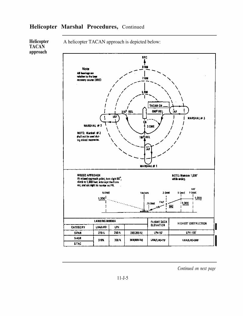
Helicopter Marshal Procedures, Continued
HelicopterTACANapproach
A helicopter TACAN approach is depicted below:
Continued on next page
11-J-5

Helicopter Marshal Procedures, Continued
Helicopteremergencymarshalpatterns
Pilots must be briefed on the emergency procedures before launch on the airplan. These procedures presume that an aircraft has operable TACANazimuth and DME.
An emergency pattern provides established procedures for aircraft pilots whoexperience lost communications when returning to the ship during IMC.
LHA/LHD operations are unique in that helicopter final recovery timescannot be predicted because hot refueling can extend mission times. Anemergency marshal procedure must be used that will remain in effect and notrequire an update even when the aircraft's final recovery time is extended byhot refueling. The helicopter emergency marshal procedures provide for therecovery of 24 individual helicopters experiencing lost communications ofIMC.
The aircraft, on the ship's air plan, are assigned an emergency marshal point.Radial, DME, EEAT, and altitude assignments are based on the marshalpoint assigned. The marshal point assigned must not be changed during theaircraft's event except as requested by the pilot or HDC and only with theapproval by both parties.
Some special notes concerning helicopter emergency marshal patterns arelisted below:
During mixed aircraft operations, helicopters must cross the EFB ator above 2,000 feet.TACAN marshal three conflicts with the emergency marshal pattern.Helicopter airspeed throughout the emergency marshal pattern is 90knots except during holding when fuel must be conserved.
Continued on next page
11-J-6

Helicopter Marshal Procedures, Continued
Helicopteremergencymarshalpatterns(continued)
Amphibious helicopter emergency marshal patterns are depicted below:
Continued on next page
11-J-7

Helicopter Marshal Procedures, Continued
Helicopteremergencymarshalaltitudes andEEATs
Amphibious helicopter emergency marshal altitudes and EEATs are listed inthe following table:
Marshal point Marshal radial DME Altitude EEAT EEAT(relative degrees) (16 helos) (24 helos)
1st 2nd
A5
A6
A7
A8
A9
A10
A11
A12
B5
B6
B7
B8
B9
B10
B11
B12
C 5
135
135
135
135
135
135
135
135
090
090
090
090
090
090
090
090
045
5
6
7
8
9
10
11
12
5
6
7
8
9
10
11
12
5
1500
2000
2500
3000
3500
4000
4500
5000
1500
2000
2500
3000
3500
4000
4500
5000
1500
00
01
02
03
04
05
06
07
13
14
15
16
17
18
19
20
21
3 0
31
32
33
34
35
36
37
43
44
45
46
47
48
49
50
51
00
01
02
03
04
05
06
07
13
14
1 5
16
17
18
19
20
26
Continued on next page
11-J-8

Helicopter Marshal Procedures, Continued
Helicopter Table continued from page 11-J-8.
(continued)
emergencymarshalaltitudes andEEATs
Marshal point Marshal radial DME Altitude EEAT EEAT(relative degrees) (16 helos) (24 helos)
1st 2nd
C6
C 7
C 8
C9
C10
C11
C12
045
045
045
045
045
045
045
6
7
8
9
1 0
1 1
1 2
2000
2500
3000
3500
4000
4500
5000
2 2
2 3
2 4
2 5
2 6
2 7
2 8
5 2
5 3
5 4
5 5
5 6
5 7
5 8
2 7
2 8
2 9
3 0
3 1
3 2
3 3
Helicopter The following notes apply to amphibious helicopter emergency marshalemergency patterns:marshalpattern notes Pilots proceed outbound from the ship and climb or descend to their
assigned emergency marshal altitude.
Continued on next page
11-J-9

Helicopter Marshal Procedures, Continued
Helicopteremergencymarshalpattern notes(continued)
Pilots proceed directly to their assigned emergency marshal fix/point.Pilots make right turns in holding with 2-mile legs.Pilots must report established in the holding pattern with fuel state andsouls onboard.At their assigned EEAT, pilots depart the marshal fix and proceedinbound descending to 500 feet. Pilots must report departing withcurrent fuel state.At 5 DME, pilots arc clockwise to intercept the 180 degree relativeradial and proceed inbound.At the FAF (3 DME), pilots begin descent and report at the FAF withcurrent fuel state.Pilots should watch for a light from the tower and land on the LSE'ssignal.
Helicopteremergencymarshalexplanation
Each aircraft is assigned an emergency marshal point prior to launch on theair plan. If a helicopter assigned marshal point C6 experiences lostcommunications in IMC, the pilot proceeds to the 045 degree relative radial.Once established on this radial, the pilot enters holding at 6 DME and analtitude of 2,000 feet. The pilot commences approach at the preassignedEEAT (either 22 or 52 minutes past the hour).
For example, if the time is 1515Z, the pilot commences approach at 1522Z.If the time is 1535Z, the pilot commences approach at 1552Z.
11-J-10

V/STOL Aircraft Marshal Procedures
Introduction
Case II/IIIV/STOLmarshalpattern
V/STOLdepartingmarshalprocedures
V/STOL aircraft marshal operations are normally faster paced than helicoptermarshal operations. This section covers the basic procedures you need toknow for conducting V/STOL marshal operations.
The TACAN primary marshal is on the 180 degrees radial at a distance of 1mile for every 1,000 feet of altitude plus 15 miles (angels plus 15). The basealtitude assigned must not be less than 6,000 feet.
The TACAN overhead marshal is an overhead holding pattern in whichaircraft proceed inbound on a 210 degree bearing at an altitude as assigned(not less than 6,000 feet). Aircraft fly a 2-minute, racetrack pattern bymaking left-hand turns with the inbound leg passing over the holding fix.
The following procedures apply to V/STOL aircraft that depart frommarshal:
Operational/weather conditions permitting, aircraft are cleared todepart marshal every 2 minutes.Descent from marshal must be at 250 knots, 4,000 to 6,000 feet perminute, until platform (5,000 feet). At platform, the rate of descentmust be reduced to arrive at the 12-mile gate at 1,200 feet. Aircraftmust transition to landing configuration at the gate.Aircraft on a TACAN or radar approach must correct from themarshal radial to the final bearing at 20 miles. When the finalbearing is within 10 degrees of the reciprocal of the marshal radial,the pilot must make a gradual correction. When the final bearing isgreater than 10 degrees, the pilot must turn 30 degrees. If the aircraftis not established on the final bearing at 12 miles, the pilot must fly a12-mile arc until intercepting the final bearing.
Continued on next page
11-J-11

V/STOL Aircraft Marshal Procedures, Continued
V/STOLdepartingmarshalprocedures(continued)
Pilots flying an overhead TACAN approach must correct to the finalbearing, if it decreases, by flying 90 degrees of penetration turn andarcing to the new bearing. If the final bearing increases, aircraft flythe standard penetration turn and continue to intercept the new finalbearing before the 12-mile gate.
"Signal The following DELTA procedures apply when a delay is anticipated orDELTA" needed:
Aircraft in holding must continue and wait assignment of new EATs.The pilots must acknowledge a signal DELTA.Aircraft on approach above platform must level off at the next lowerodd-numbered altitude and hold on the inbound bearing at a range inmiles equal to the holding altitude in thousands of feet plus basedistance (angels plus 15). The pattern must be the same as theoriginal marshal pattern. Pilots must acknowledge receipt of DELTAand repeat distance and altitude information.Aircraft on approach at platform or below platform must continue anormal approach and await specific instructions from the controllerbefore they dump fuel.When possible, a new EAT must be assigned with a minimum of 6minutes before descent is continued. If the pilot loses radiocommunications before he or she receives a new EAT, the pilot mustdepart the holding fix at 6 minutes past the time of receiving a DELTAand proceed to the TACAN emergency marshal assigned and holduntil the preassigned EEAT.
Continued on next page
11-J-12

V/STOL Aircraft Marshal Procedures, Continued
V/STOLemergencymarshalprocedures
The emergency marshal for V/STOL aircraft must be on the 150-degreerelative radial at 1,000-foot intervals commencing at 5,000 feet. The DMEmust be angels plus 15 miles.
After pushover, the aircraft tracks inbound on the 150-degree relative radial,levels at 1,200 feet, and turns to intercept the 12-mile arc. The aircraft flieson the 12-mile arc until it intercepts the emergency final bearing and executesthe final portion of the TACAN approach. If an aircraft is unable to land, itmust fly the missed approach as published on the TACAN procedure. Entryinto the holding point must be at the assigned angels.
Continued on next page
11-J-13

V/STOL Aircraft Marshal Procedures, Continued
V/STOLemergencymarshalpattern
The V/STOL emergency marshal pattern is depicted below:
11-J-14

Approach Procedures
Introduction As an approach or final controller on an amphibious ship, you provide the finalcontrol instructions to aircraft for recovery on the ship or handoff to PriFly.The pilot depends on you to provide accurate course information. Thisinformation becomes critical in IMC.
Case Ihelicoptervisual descentand approach
Case I is used only when it can be anticipated that flights will not encounterIMC at anytime during the descent, break, and final approach.
During mixed aircraft operations the following procedures apply to helicopterrecovery operations:
Helicopters must enter the starboard delta pattern located 1 mile to thestarboard side of the ship at 300 feet and oriented on the BRC.
The helicopter break altitude must not exceed 300 feet.
Pilots must report see you when they have visual contact with the ship inVMC. If the flight is in VMC, AOCC/HDC switches the flight to PriFly'sfrequency at 5 nautical miles.
Continued on next page
11-J-15

Approach Procedures, Continued
Charlie and Normally, when the ship's deck is ready for recovery, helicopters enter thestarboard delta charlie pattern. If the ship's deck is not ready for recovery or a delay ispatterns necessary, helicopters enter the starboard delta pattern. Both the charlie and
the starboard delta patterns are depicted below:
Continued on next page
11-J-16

Approach Procedures, Continued
Case IIhelicoptercontrolleddescent/visualapproach
During Case II helicopter approaches, AOCC/HDC are required to use close(positive) control until the flight leader/pilot reports the ship in sight.AOCC/HDC must be fully manned and ready to assume a Case III recoveryshould the weather deteriorate below Case II minima.
Note: Case II approaches must not be flown when Case III departures are inprogress. Case III approaches must be used during marginal VMC.
Case IIIhelicopterapproach
Case III recoveries apply to single aircraft only. The exception to the single-aircraft requirement is when an aircraft that is experiencing difficulties isrecovered on the wing of another aircraft. Formation flights by dissimilaraircraft must not be attempted except in extreme circumstances when no safermethods are available. Whenever possible, precision approach radar must beused.
Case I V/STOLvisual descentand approach
The same criteria and check-in procedures apply to V/STOL aircraft asoutlined for helicopters except for the following:
The pilot should plan his or her descent so that the aircraft arrives atthe initial point, 3 miles astern, 800 feet, wings level, and parallel tothe BRC.The flight leader must report to PriFly when descending from thedelta pattern and arriving at the initial point (IP).Each flight must execute a normal break not more than 5 miles aheadof the ship.
Continued on next page
11-J-17

Approach Procedures, Continued
Case II During Case II V/STOL approaches, close (positive) control by AOCC/HDCV/STOL is mandatory until the pilot reports see you at which time normal Case Icontrolleddescent/ visual
procedures apply.
approach If the first flight is unable to gain and maintain visual contact with the ship atthe 12-mile gate, a controlled descent to break altitude (800 feet) must beinitiated at the gate. If less than Case II weather exists at 5 miles,AOCC/HDC is required to vector the first flight into the waveoff pattern andto a Case III marshal pattern. Case III approach procedures are thenmandatory for recovery of aircraft that arrive thereafter.
Case III During Case III, V/STOL aircraft are required to descend to arrive at theV/STOL 12-mile gate at an altitude of 1,200 feet. Unless otherwise directed, aircraftapproach must transition to landing configuration at the 12-mile gate.
NOTE: Unless an aircraft is in level flight, radio frequency changes are notauthorized below 2,500 feet.
Approachminimums
The following table lists the approach minimums for V/STOL aircraft:
V/STOL Aircraft
Type of Approach Minimums (ceiling and visibility)
S-PAR day 300 feet and 1 mile
S-PAR night
S-ASR
400 feet and 1 mile
500 feet and 1 1/2 mile
S-TAC 500 feet and 1 1/2 mile
Continued on next page
11-J-18

Approach Procedures, Continued
Approachminimums(continued)
The following table lists the approach minimums for helicopters:
Helicopters
Type of Approach Minimums (ceiling and visibility)
S-PAR 200 feet and 1/2 mile
S-ASR 400 feet and 3/4 mile
S-TAC 400 feet and 3/4 mile
Continued on next page
11-J-19

Approach Procedures, Continued
V/STOLTACANapproach
A TACAN approach for V/STOL aircraft is depicted below:
Continued on next page
11-J-20

Approach Procedures, Continued
Additionalinformation
For a complete description of amphibious air traffic control procedures, referto LHA/LPH/LHD NATOPS Manual, NAVAIR 00-80T-106, and AmphibiousShips Air Traffic Control Manual, AE-LHATC-OPM-000.
11-J-21


CHAPTER 12
FACILITY OPERATIONS
Overview
Introduction This chapter covers issues you will encounter in the management of an ATCF,Certain ATC management procedures are addressed, and some additional areasare highlighted that will be essential to you when you become a manager at anATCF. Required reports and general administrative duties are also covered.
Not every responsibility of the rating can be covered in this chapter. It is yourresponsibility to be familiar with the publications, directives, instructions, and"rules of the road." This chapter should point you in the right direction andprovide you with the basic knowledge required to perform as a manager at anATCF.
Objectives The material in this chapter will enable you to:
List the duties and responsibilities of ATC management billets.Describe some of the personnel management requirements specific to theAC rating.Identify the procedures for collecting data and investigating an accidentor incident.Identify an operational error and an operational deviation.Recognize those portions of FAR, Part 65, that apply to the issuance ofATC tower operator certificates and ratings and the regulationsgoverning the use of those certificates and ratings.Discuss the requirements involved for issuing an ATCS certification.Define the procedures for the suspension and/or revocation of an ATCScertificate.Describe the training specific to the AC rating.Identify the special programs unique to the ATC rating and discuss therequirements and importance of each.Explain the various facility reports and logs maintained at an ATCF.
Continued on next page
12-1

Overview, Continued
Objectives Discuss the purpose and function of the ATC contingency plan.(continued) Define the different types of flight inspections and their purposes.
Acronyms The following table contains a list of acronyms that you must know tounderstand the material in this chapter:
Acronym Meaning
AATCFO
AC
Assistant ATCF officer
Air traffic controller
Air Ops Air operations
ARTCC Air route traffic control center
ASR Airport surveillance radar
ATC Air traffic control
ATCF
ATCFO
Air traffic control facility
ATCF officer
ATCRBS Air traffic control radar beacon system
ATCS Air traffic control specialist
Counseling and assistance centerCAAC
CEB Controller evaluation board
CP Command post
CTO Control tower operator
FAA Federal Aviation Administration
FAR Federal Aviation Regulations
FOIA Freedom of Information Act
Continued on next page
12-2

Overview, Continued
Acronyms(continued)
Table continued from page 12-2.
Acronym Meaning
FWS Facility watch supervisor
GEMO Ground electronics maintenance officer
HAT Height above touchdown
hr Hour
IFR Instrument flight rules
LDO Limited duty officer
LCPO Leading Chief Petty Officer
NAS Naval air station
NAVREP Navy representative to the FAA
NMCC National military command center
OJT On-the-job training
PAR Precision approach radar
PEB Procedures evaluation board
PTH Productive training hour
SESEF Shipboard electronic systems evaluation facility
TERPS Terminal instrument procedures
VFR Visual flight rules
Continued on next page
12-3

Overview, Continued
Topics This chapter is divided into the following seven sections:
Section Topic SeePage
A Facility Organization and Management 12-A-1
B Aircraft Accidents and Incidents 12-B-1
C Certification Program 12-C-1
D Training 12-D-1
E Facility Administration 12-E-1
F ATC Contingency Plan 12-F-1
G Flight Inspections 12-G-1
12-4

Section AFacility Organization and Management
Overview
Introduction Management positions play a vital role in the effective operation of anATCF. Certain management issues require the involvement of bothmanagement and supervisory-level controllers in determining facility policies.
In this section This section covers the following two topics:
Topic See Page
Management Positions 12-A-2
General Management Issues 12-A-5
12-A-1

Management Positions
Introduction The ATCF's management team provides the critical guidance, decisionmaking, and supervision required for the daily operations of an ATCdivision. Normally, this team consists of an AC LDO and one or more ACChiefs, Senior Chiefs, or Master Chiefs. The size and operationalrequirements of the facility determine the number and types billets establishedfor each ATC division.
ATCF officer(ATCFO)
Assistant ATCF The AATCFO assists the ATCFO in the management and administration ofofficer the facility. The duties and responsibilities of the AATCFO include the(AATCFO) following:
The ATCFO is ultimately responsible for the overall management of the airtraffic control facility. Normally, the ATCFO is an air traffic controlLimited Duty Officer (LDO). The duties and responsibilities of the ATCFOinclude, but are not limited to, the following:
Ensuring proper coordination and control of air traffic within theATCF area of jurisdictionEstablishing standard operating proceduresInitiating collection of data relating to accidents and incidents andsafeguarding the dataEnsuring training, supervision, and assignment of ATC personnelConducting liaison with NAVREPs, FAA representatives, andrepresentatives of other agenciesDetermining qualification of ATC personnelCoordinating with the Ground Electronics Maintenance Officer(GEMO) on requests for equipment replacement or enhancement
Providing interface with the FAA and other military facilitiesDeveloping, reviewing, and standardizing ATC procedures
Continued on next page
12-A-2

Management Positions, Continued
Leading chiefpetty officer(LCPO)
Branch chief
Training chief
Facility watchsupervisor(FWS)
The LCPO works closely with the ATCFO in the administration,supervision, and training of assigned personnel. This includes coordinatingthe assignment and supervision of enlisted personnel within the air trafficcontrol facility. The LCPO also assists the ATCFO by makingrecommendations concerning improvement of spaces, procedures, workingconditions, and the welfare and morale of enlisted personnel.
Each branch in the facility must have a branch chief assigned. We will giveonly a general summary of the responsibilities of these positions. The branchchief has overall responsibility for that particular branch. The branch chiefalso ensures that proper training is conducted and closely monitors eachcontroller's progress.
The training chief must meet certain qualifications to hold this position.These qualifications include the following:
Having all ATCS ratings for the facility assignedBeing qualified as an FWSHaving a minimum of 5 years' experience in ATC
As a training chief, your function will be to plan, execute, and supervise theATC facility training, certification, and standardization programs. Refer toNATOPS Air Traffic Control Facilities Manual, NAVAIR 00-80T-114, for acomplete description of the duties and responsibilities of the training chief.
During the hours of operation, each facility must have an FWS designated bythe commanding officer on duty at the ATCF. The FWS must be qualifiedon all operating positions within the facility. The FWS is responsible to thecommanding officer or his or her designated representative for theoperational performance of the watch crew on duty. At the discretion of theATCFO, the duties of the FWS can be combined with those of a branchsupervisor but should not normally be assigned to a control position. Duties,responsibilities, and authority of the FWS include the following:
Continued on next page
12-A-3

Management Positions, Continued
Facility watch FWS equipment responsibilities include, but are not limited to thesupervisor(FWS)(continued)
following:
–Assuring an equipment checkout is performed at the beginning ofeach shift–Reporting any equipment malfunction to the electronics maintenancedivision–Reporting any derogation or essential services to appropriateagencies such as ARTCCs
FWS watch duties include, but are not limited to the following:
–Assuring proper crew briefing and an orderly watch turnover–Preparing operating position assignments–Assuring controller currency–Accomplishing and documenting training–Assuring use of proper control procedures and techniques–Assuring effective coordination within the facility and interactingfacilities–Assuring corrective action taken whenever control deficiencies arefound
FWS administrative duties include, but are not limited to the following:
–Receiving complaints from pilots and adjacent facilities regardingATC services or procedures provided by the ATCF and accumulatinginitial data for forwarding to the ATCFO–Accumulating and performing the initial documentation of accidentand incident records and forwarding these records to the ATCFOimmediately–Checking and signing daily facility logs and forwarding them to theLCPO or branch chief as dictated–Ensuring physical security of all assigned spaces
12-A-4

General Management Issues
Introduction ATCF management personnel encounter a variety of controller and facilityissues that require input from facility controllers and strict adherence toestablished regulations.
Facility boards, hours of duty, and operating position guidelines are examplesof some of the key management issues.
Controller Sometimes, a controller's training progress is unsatisfactory or requiresevaluation modification. The purpose of the CEB is to make recommendations to theboard (CEB) ATCFO and evaluate the following:
The training status and progress of controllers—identifying those whoare not progressing satisfactory or who have not been able to meettraining schedulesThose controllers whose performance or training record indicateunsatisfactory performance or inability to master the complexities ofthe AC ratingOther matters deemed appropriate by either the ATCFO or LCPO
The ATCFO determines the composition of the CEB.
Proceduresevaluationboard (PEB)
Have you ever felt that you knew a better way to perform a certain ATCprocedure? Well, the PEB is a means for a controller to take an active rolein developing ATC procedures for their facility. As a member of the PEB,you and the other board members are tasked with evaluating existing and newATC procedures for accuracy and improvement. The PEB then forwards anyactions or modifications they recommend to the ATCFO for approval.
Hours of duty ATCF operational requirements dictate the hours that a facility (controltower, radar room, flight planning, etc.) will be manned. In an emergencyor operational necessity situation, these normal working periods may beextended in accordance with FAR, Part 65. Specifically the regulationconcerning working hours can be stated as follows:
Continued on next page
12-A-5

General Management Issues, Continued
Hours of duty(continued) Except in an emergency, a certified air traffic control tower operator must
be relieved of all duties for at least 24 consecutive hours at least onceduring each 7 consecutive days. Such an operator may not serve or berequired to serve
for more than 10 consecutive hours orfor more than 10 hours during a period of 24 consecutive hoursunless the controller has had a rest period of at least 8 hours ator before the end of the 10 hours of duty.
As a facility manager, it is your responsibility to monitor the working hoursof the controllers assigned to your facility.
Operatingpositions
The number and types of positions established for a facility are directlyrelated to the ATC function performed by that facility. Also, the volume oftraffic influences the overall number of operating positions. During periodsof light traffic certain positions may be combined provided the controller isfacility-rated or qualified on each of the combined positions. ATCFOs mustensure that the operating positions that are authorized to be combined arespecified in local ATC facility directives. It is your responsibility as amanager to periodically review these directives and make recommendationsto the facility officer.
Traineesassigned tooperatingpositions
When trainees are assigned to operating positions, they must be under thedirect supervision of a controller qualified on the position concerned. Thequalified controller retains ultimate responsibility for the position and mustuse the same radio console unless override capability exists from an adjacentconsole.
Final controltrainees
Trainees must not be assigned as a final controller (precision or surveillance)when the ceiling is below 1,000 feet or the visibility is less than 3 miles.With written approval of the radar chief, trainees that are nearingqualification or who have been qualified as a final controller at anotherATCF may be authorized to control aircraft conducting radar approachesunder weather conditions established by the ATCFO.
12-A-6

Section BAircraft Accidents and Incidents
Overview
Introduction You must know the correct data collection procedures for ATC accidents orincidents and be able to distinguish the difference between an ATCoperational error and operational deviation.
In this section This section covers the following two topics:
Topic See Page
Accident and Incident Data Collection Procedures 12-B-2
Operational Errors and Deviations 12-B-6
12-B-1

Accident and Incident Data Collection Procedures
Introduction The importance of collecting accurate data following an accident or incidentcannot be overemphasized. An incident can be anything from pilot deviationthat results in a flight violation to a near midair collision. An accident isself-explanatory; it can be as minor as one aircraft taxiing into another or asmajor as an accident that results in aircraft loss or death.
Naval Aviation Safety Program, OPNAVINST 3750.6, contains guidanceconcerning investigations. Involvement of a civilian aircraft or civilianproperty should be reported via OPREP 3 NAVY BLUE in accordance withSpecial Incident Reporting (OPREP-3, Navy Blue and Unit SITREP),OPNAVINST 3100.6.
General Following an accident/incident, ATCF supervisory personnel are required to:
notify appropriate personnel as outlined in local directives,request and obtain a weather observation, andensure pertinent tapes are removed and safeguarded.
As the branch chief, you are required to investigate each accident/incident.You must determine who was involved and the circumstances that might havecaused the accident/incident. Naturally, there are almost always two sides toevery story. Playbacks of audio and video recordings can help you decidewhich story is most accurate.
Transcription All formal accident packages are required to contain the followinginformation:
A typewritten transcript.All recorded communications that concern the subject aircraft for aperiod of 5 minutes before initial contact until 5 minutes after theaccident.A chronological summary of the aircraft's flight.
Continued on next page
12-B-2

Accident and Incident Data Collection Procedures, Continued
Transcription NOTE: It is a requirement that transcriptions must be made from the copy(continued) of the voice recording rather than from the original recording to protect the
original from wear or damage.
Tapes Requests for viewing or duplicating original recordings that may be evidencein a non-U.S. Government investigation must be referred to CNO (N885F).In addition tapes or information that pertain to an accident must not bereleased to any party without the consent of the appropriate commandingofficer. A chain of custody (with signatures obtained including release andassumption of responsibility) is mandatory and must be established for alloriginal voice or video recordings before release of recordings to authorizedagencies or officials. The Freedom of Information Act as delineated inDepartment of the Navy Freedom of Information Act (FOIA) Program,SECNAVINST 5720.42, should be referred to in all cases. For the properformat in transcribing tapes, refer to NATOPS Air Traffic Control FacilitiesManual, NAVAIR 00-80T-114.
Retention of Original recordings must be retained for at least 15 days except for mishapsvoice and video involving Navy ATCFs or DON aircraft. These mishap recordings must berecordings retained until one of the following events occurs:
The two-year statute of limitations expires.Higher authority releases the recordings.
The claim or complaint is adjudicated.
Statements Statements must be obtained from the controller and supervisory personnelinvolved. These statements are in support of administrative action and maynot be made the basis of legal or disciplinary proceedings unless provisionsof Article 31 of the UCMJ have been observed. You can find the format forthese statements in NATOPS Air Traffic Control Facilities Manual, NAVAIR00-80T-114.
Equipmentcondition
The operating characteristics and condition of equipment (such as the FPN-63) must be examined by technically qualified personnel who were not onduty at the time of the accident/incident.
Continued on next page
12-B-3

Accident and Incident Data Collection Procedures, Continued
Equipment This procedure is used to determine whether equipment could have been acondition contributing factor. Before the examination no alterations or adjustments(continued) must be made on the equipment without the consent of the ATCFO.
ATC personnelinvolvement inan accident orincident
An air traffic controller that appears to have contributed to an accident or toan incident that jeopardized safety of aircraft must be temporarily relieved ofoperational duty. The controller must also be referred to the flight surgeonfor physical/psychological evaluation. As is the case with the statements, thisis not to be considered as disciplinary or punitive action. Relief fromoperational duty is to remain in effect until the ATCFO has determined theprobability of controller involvement.
Preliminaryinvestigation
If, after the preliminary investigation the controller is found NOT to be aresponsible or a contributing factor, the controller will be returned tooperational duty.
If, after the investigation the controller IS found to be responsible, thefollowing action must be taken as a minimum prerequisite to reassignment tooperational duty:
A detailed and complete review of the accident/incident should takeplace with the controller including a discussion of circumstancesrelated to the accident/incident.A reevaluation of the controller on the position(s) to determine ifadditional training is necessary.If retraining is required, it should be conducted with particularemphasis on any weakness revealed during the investigation of theaccident/incident.
Retraining, including demonstration of a skill level at least equal to thatrequired for the appropriate portion of sector/position "check-out," is to beconsidered a recertification of control ability.
Continued on next page
12-B-4

Accident and Incident Data Collection Procedures, Continued
Disciplinaryaction
In some cases of carelessness or negligence, disciplinary action is apossibility. Owing to the seriousness of such action to the controller, use ofthe terms carelessness or negligence must be carefully considered. Use theseterms only in cases where the controller is careless or negligent beyond areasonable doubt.
If there is personal injury or property damage, a lawsuit may be filed.Should a lawsuit occur, the files and records relating to the investigation ofthe instances, and any disciplinary or other actions taken, may be subject todisclosure to the attorneys for the litigants and produced in court.
If disciplinary action appears warranted, action must be initiated inaccordance with appropriate military and/or Office of Personnel Managementdirectives.
12-B-5

Operational Errors and Deviations
Introduction While an aircraft receives ATC services, operational errors or operationaldeviations sometimes take place. Errors and deviations occur because ATCequipment, ATC procedures, or other air traffic system elements fail.Failures result in a departure from standards contained in operating manuals,handbooks, or supplementary instructions.
Operational An operational error is defined as an occurrence attributable to an element oferrors the air traffic system that results in one or both of the following occurrences:
Less than the applicable separation minima between two or moreaircraft, or between an aircraft and terrain or obstacles, as required byAir Traffic Control, FAA 7110.65, and supplemental instructions.Obstacles include vehicles, equipment, or personnel on runways.An aircraft lands or departs on a runway closed to aircraft operationsafter receiving air traffic authorization.
Operationaldeviation
An operational deviation is a controlled occurrence where applicable minimalseparation was maintained, but one or more of the following situationsoccurs:
Less than the applicable separation minima existed between an aircraftand protected airspace without approvalAn aircraft penetrated airspace that was delegated to another positionof operation or another facility without coordination and approvalAn aircraft penetrated airspace that was delegated to another positionor to another facility at an altitude or route contrary to the altitude orroute requested and approved in direct coordination or as specified ina LOA, precoordination, or internal procedureAn aircraft, vehicle, equipment, or personnel encroached upon alanding area that was delegated to another position of operationwithout prior coordination and approval
Continued on next page
12-B-6

Operational Errors and Deviations, Continued
Procedures for A person who is aware of an operational error or suspected operational errorreporting is required to report the error to supervisory personnel immediately. Theoperational supervisor, in turn, must brief the ATCFO. The ATCFO reports the error inerrors accordance with locally developed procedures. In addition to local reports,
the ATCFO must send a message report on all operational errors to CNO(N885F), the appropriate NAVREP, the Naval Safety Center Code 114, andtype commander within 3 working days. NATOPS Air Traffic ControlFacilities Manual, NAVAIR 00-80T-114, specifies the format for thismessage report.
12-B-7


Overview
Section CCertification Program
Introduction All air traffic controllers, both military and civilian, must be certified andfacility-rated in accordance with FAR, Part 65.
NATOPS Air Traffic Control Facilities Manual, NAVAIR 00-80T-114,establishes the Navy's certification process and augments and amplifies thecertification procedures prescribed in the FAR, Part 65. In addition to anAirman Written Test, this manual also requires Navy air traffic controllers tohave an Air Traffic Control Specialist (ATCS) certificate,FAA Form 7220-1.
The overall certification program has three parts: certification, facilityrating, and proficiency training. Two factors must be considered indetermining the job proficiency of an air traffic controller: (1) a written testto determine that a controller has a thorough knowledge of the basic rules andregulations, and (2) a practical test to determine the controller's ability toapply this knowledge under actual traffic conditions.
In this section This section covers the following topic:
Topic See Page
Navy ATC Certification Process 12-C-2
12-C-1

Navy ATC Certification Process
Introduction To be an air traffic controller in the Navy, personnel must meet certainmedical and specific AC rating requirements.
In accordance with the physical standards established in the Manual of theMedical Department, military air traffic controllers must maintain a currentannual physical. Additionally, each controller must have a current ClearanceNotice (Aeromedical), NAVMED 6400/2, on file when he or she provides orsupervises ATC services.
requirementsMedical
Initialrequirements
Naval personnel must have completed the following initial requirements:
Satisfactorily completed the FAA airman written test for CTOs (ACForm 8060-37/8080-2)Be a graduate of a U.S. military air traffic controller formal basiccourse of instruction that included PAR practical application
Certificates The following three certificates are issued to Navy air traffic controllers:
Airman written test for CTOs (AC Form 8060-37/8080-2). Thisairman certificate signifies that the applicant has satisfactorily passedthe FAA written examination for Control Tower Operator. This isthe minimum requirement for entry into the AC field. Thiscertificate is obtained upon successful completion of AC(A1) school.Control Tower Operator (CTO) Certificate (AC Form 8060-1).This airman certificate is also administered by the FAA. It indicatesthat the holder is qualified to perform the duties of a control toweroperator at a particular airport (e.g., NAS Whidbey Island, WA,control tower). This certificate is issued after the individual haspassed locally prepared CTO facility rating examinations and apractical applications test.
Continued on next page
12-C-2

Navy ATC Certification Process, Continued
Certificates(continued)
Air Traffic Control Specialist (ATCS) Certificate (FAA Form7220-1). This certificate is issued to Navy personnel by the authorityof the Chief of Naval Operations and authorizes the holder to performthe duties as a Navy Air Traffic Controller. Each Navy controller isrequired to have the ATCS certificate whether they are working inradar or the tower. Navy controllers receive their initial certificateupon successful completion of AC(A1) school.
Facility ratings A facility rating is an endorsement to the ATCS Certificate (FAA Form7220-1) that signifies that the applicant has demonstrated the competence,qualifications, and skills required to control air traffic at a specific location,for example, NAS Lemoore, CA. The following table contains a list of theATCS ratings that are documented on the back of the ATCS certificate:
Type Rating Meaning
AOCC Qualified on all positions specified for air traffic controllersassigned to an AOCC/HDC
APC Qualified as an approach controller at a nonradar (manual)approach control facility
ARTCC Qualified on all positions in the radar branch of the CERAPincluding the en route portion
BASEOPS Qualified on all positions in base operations. This rating iscan only be issued at Class 1 ATCFs
CATCC Qualified on all positions in a CCA
FACSFAC
GCA
Qualified on all ATC positions at a FACSFAC
Qualified on all positions in a GCA unit
RATCF Qualified on all positions within the radar branch excludingapproach control
RFC Qualified as an ASR, PAR, and where applicable PALS finalcontroller
Continued on next page
12-C-3

NAVY ATC Certification Process, Continued
Facility ratings(continued)
Authority tosuspend orrevoke CTOratings orcertificates
Authority tosuspend orrevoke ATCSratings andcertificates
Suspension ofATCS ratings
Table continued from page 12-C-3.
Type Rating Meaning
TACC Qualified on all positions specified for air traffic controllersassigned to a tactical air control center
TRACON Qualified on all positions within the radar branch of anapproach control facility
NOTE: Qualification in supervisory positions such as radar supervisor is notrequired for the issuance of a particular rating. Also, ATCS ratings are notthe same as CTO ratings.
With ATCFO concurrence, the CTO Examiner may suspend a CTO rating.
To revoke the CTO certificate of a controller, the ATCFO forwards his orher recommendation to revoke to CNO (N885F). If in agreement, CNO willendorse and forward the recommendation to the FAA. The FAA has finalrevocation authority for CTO certificates.
The commanding officer may suspend or revoke an ATCS facility rating.However, CNO (N885F) is the final revocation authority for ATCScertificates issued under the authority delineated in NATOPS Air TrafficControl Facilities Manual, NAVAIR 00-80T-114.
A rating must be suspended when controller performance of duties adverselyaffects the facility's efficiency or safety of flight. In addition, ATCFmanagement is required to suspend controllers from ATC duties whennotified by CAAC personnel of alcohol dependency or drug abuse bycontrollers.
The ATCFO must have the following entry made in the suspendedcontroller's certification/qualification record:
"(Type) rating suspended."
Continued on next page
12-C-4

Navy ATC Certification Process, Continued
Revocation of If the ATCFO decides to revoke a controller's ATCS rating, he or she mustATCS ratings notify the controller promptly in writing. The revocation of a rating must be
reflected on the ATCS certificate, in the certificate/qualification record, andin the controller's service record.
When an ATCS rating has been suspended but ATCS certificate revocation isnot contemplated, the ATCS rating can be reissued. Reissuance occurs oncethe controller requalifies on all applicable positions in the time allotted inNATOPS Air Traffic Control Facilities Manual, NAVAIR 00-80T-114.
When to ATCS certificate revocation should be considered in the following cases:considerrevocation ofthe ATCS
Negligence that has caused an accident
certificateAlcohol or drug abuse in accordance with Substance Abuse Preventionand Control, OPNAVINST 5350.4Medically diagnosed physical, character, or behavior disorder orcondition which renders a controller NPQ or not aeronauticallyadaptable for ATC duties and for which a waiver of standards has notbeen granted by CHNAVPERSFailure to make satisfactory progress to obtain an ATCF rating withinthe time frames established in NATOPS Air Traffic Control FacilitiesManual, NAVAIR 00-80T-114.Professed or diagnosed anxiety (fear of controlling)Questionable moral character evidenced by documented recurrentantisocial behavior
ATCSreinstatement
Personnel who meet the requirements for reinstatement may apply to CNO(N885F) via the chain of command through an aviation type commander.Reinstatement must not be considered in some cases. These cases include:
Negligence that caused an accidentProfessed or diagnosed anxiety (fear of controlling)Failure to make satisfactory progress to obtain ratingDrug abuse
Reinstatement requirements are listed in NATOPS Air Traffic ControlFacilities Manual, NAVAIR 00-80T-114.
12-C-5


Section DTraining
Overview
Introduction Throughout your career as an air traffic controller, you have been in constanttraining. Like everyone else, you more than likely made the statement:"Why are we having training again?" Training cannot be overemphasized,especially in a rating as complex as ours. We experience continual changesand updates to rules, directives, and instructions.
All of us have heard about facilities that are "short" of controllers. To bemore realistic, these facilities are probably short of qualified controllers.Due to workforce reductions, facilities must do more with less. Therefore, itis crucial that you, as a facility manager, establish an effective trainingprogram to produce quality controllers in the shortest time possible.
In this section This section covers the following two topics:
Topic See Page
Controller Training Process 12-D-2
Controller Performance Evaluations 12-D-6
12-D-1

Controller Training Process
Introduction For a new controller at an ATCF, the facility's training program is vital tosuccessful qualification on each of the ATC positions. The training programnormally centers around the trainee's use of a facility manual, air operationsmanual, lesson topic guides, local qualification standards, and performingOJT to qualify.
Productive PTH is defined as a 60-minute period during which meaningful OJT trainingtraining hours is accomplished at an operation position in relation to the trainee's level of(PTH) experience. Productive training is any period in which the trainee is afforded
the opportunity to do one or more of the following:
Experience a new situationLearn a new procedureMaster a previously taught procedure
NOTE: PTH may be acquired in whole or fractional hours.
Allotted PTH A new controller is authorized a specific amount of PTH to qualify on eachfor each position assigned. Time limitations for a position qualification must be basedposition on the maximum PTHs allotted for that position with the exception of the
radar final control position. Position qualification for the radar final controlposition is based on the number of approaches.
Continued on next page
12-D-2
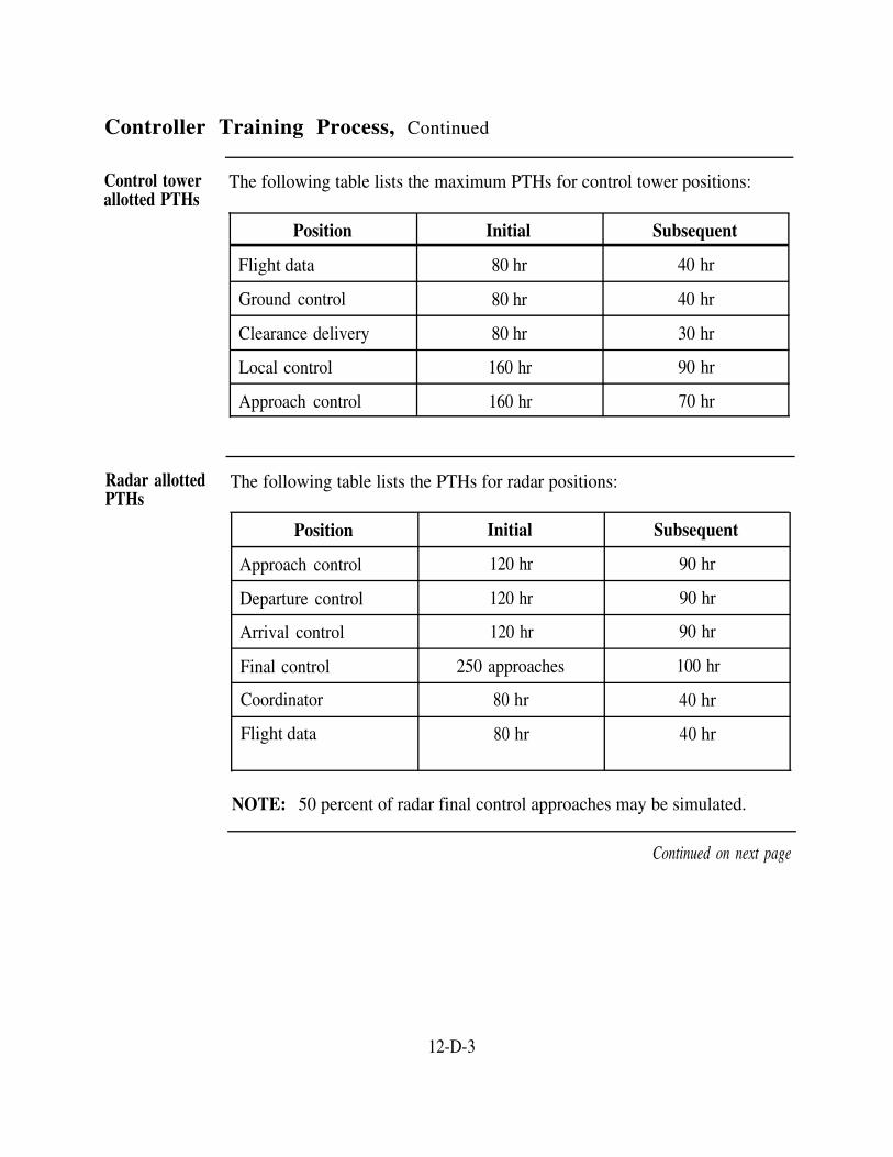
Controller Training Process, Continued
Control tower The following table lists the maximum PTHs for control tower positions:allotted PTHs
Position Initial Subsequent
Flight data 80 hr 40 hr
Ground control 80 hr 40 hr
Clearance delivery 80 hr 30 hr
Local control 160 hr 90 hr
Approach control 160 hr 70 hr
Radar allotted The following table lists the PTHs for radar positions:PTHs
Position Initial
Approach control 120 hr
Departure control 120 hr
Arrival control 120 hr
Final control 250 approaches
Coordinator 80 hr
Flight data 80 hr
Subsequent
90 hr
90 hr
90 hr
100 hr
40 hr
40 hr
NOTE: 50 percent of radar final control approaches may be simulated.
Continued on next page
12-D-3

Controller Training Process, Continued
FACSFAC The following table lists the PTHs for FACSFAC positions:allotted PTHs
Position Initial
Flight data 40 hr
Sector controller 120 hr
Assistant sector controller 120 hr
Subsequent
30 hr
60 hr
60 hr
NOTE 1: Initial qualification applies to controllers without previous positionqualification at the position under consideration. Subsequent qualificationapplies to controllers with previous position qualification at any facility at theposition under consideration.
NOTE 2: The ATCFO may reduce the allotted PTH based on a facility'snumber of aircraft operations and air traffic complexity.
Training The decision to terminate training can be made by the ATCFO during anydetermination stage of training if a trainee's demonstrated performance indicates an inability
to master the complexities of air traffic control. You, as a branch chief andsupervisor, are required to track each individual's performance and his or hertraining hours and ensure that all performance is documented in theindividual's training record.
Before a trainee reaches 70 percent of the allotted time on a position, youneed to counsel the individual on qualifying. When the trainee reaches 70percent of the maximum allotted position's OJT time, the followingdeterminations must be made:
If performance is satisfactory, training will continue.If performance is not satisfactory and unusual or extenuatingcircumstances have occurred, the ATCFO may grant a continuance oftraining.If performance is not satisfactory and there have been no extenuatingcircumstances, the ATCFO must not grant a continuance. At thispoint the trainee must be removed from a training status.
Continued on next page
12-D-4

Controller Training Process, Continued
Trainingdetermination(continued)
Revocation action should be initiated before 70 percent of themaximum allotted position time has elapsed if it is determined that atrainee is not progressing satisfactorily or is unable to meet trainingschedules.
Controllercurrency
Radar finalcontrolcurrency
Use of target During insufficient traffic situations and where target simulators are installed,simulators for a controller's proficiency can be maintained by using a target simulator undercurrency proper supervision. Controller proficiency by simulators must not replace
the equitable distribution of actual currency requirements. Only thecontroller actually making the approach should be permitted to count theapproach. Monitored simulated approaches are not considered adequate tomaintain currency and proficiency.
time-on-position which keeps controllers at an acceptable level ofperformance. ATCFOs shall prescribe monthly time requirements for eachoperating position.
As a supervisor/branch chief, you are responsible for ensuring that yourcontrollers maintain their currency. Currency is the minimum prescribed
Radar final controllers should not conduct final approaches during IFRconditions unless they have controlled at least 10 approaches in the precedingcalendar month. When the amount of air traffic limits proficiency,controllers qualified to control IFR traffic may concurrently count traineeapproaches they actively monitor.
12-D-5
Controller Performance Evaluations
Introduction
Annualevaluation
Tape talkprogram
ATCcertificationandqualificationrecords
Transfer andretention ofcertificationandqualificationrecords
Before recommending an individual for qualification, you should haveevaluated his or her performance. It doesn't matter if it is radar or towerpositions, ATC personnel are continually monitored. Monitoring doesn'tstop once the person is qualified.
Each qualified controller, either fully facility rated or position qualified, isrequired to have an annual evaluation.
If any controller receives an unsatisfactory evaluation, that individual must bemade aware of the deficiencies and must be reevaluated within 30 days. Ifmajor safety errors are detected, the examiner may recommend temporarysuspension of the individual’s rating pending further action.
The purpose of the tape talk program is to periodically review a controller'sphraseology, voice quality, and inter/intraphone procedures. This program isused to improve overall professionalism by making the controllers aware thattheir phraseology is subject to random monitoring and evaluation. At theminimum, a recording should be made for trainees at the 25 % level of PTHand as needed thereafter.
The ATC school provides the basic cover and startup pages for the ATCcertification and qualification record. Certification and qualification entriesare locally prepared.
When an individual transfers, the training jacket must be forwarded by thecommanding officer or his or her designated representative to the individual'snext command.
Training records are required to be retained at the facility level for a periodof 6 months after a controller transfers subsequent to ATCS revocation,separates, transfers to the Fleet Reserve, or retires. Copies may be providedto the individual upon request.
12-D-6

Section EFacility Administration
Overview
Introduction As an ATCF manager and supervisor, you are responsible for maintaining andsupervising the use of logs, files, and records. You are also tasked withpreparing facility reports and providing input to update facility manuals and airoperations manual.
In this section This section covers the following topic:
Topic See Page
Facility Logs, Manuals, and Reports 12-E-2
12-E-1

Facility Logs, Manuals, and Reports
Introduction An ATCF has many different logs, manuals, and reports with a specificpurpose and connection to facility operations.
Dailyoperations log
Each branch of an ATCF must maintain a daily operations log (FAA Form7230-4). This log should be maintained by the supervisor on duty and mustcontain the following:
Position logs
DateTime of all entriesSignature of the supervisor on dutyDescription of operational status of primary ATC equipment, for example,radar, NAVAIDS, and so forth.Changes to primary ATC equipment operational status throughout the dayEmergenciesA record of emergency generator operational checksOther items deemed appropriate by the ATC facility officer
NOTE: To eliminate duplication, the ATCFO may assign ATC equipment tospecific branches for log entry purposes.
A position log (FAA Form 7230-10) must be maintained for each operatingposition in the facility. The purpose of this log is to ensure that a formalturnover of relief occurs and to establish a reliable record of position manning.These logs must contain the following information:
DateTimePositionController-operating initials. (If the position is operated by a trainee,the trainee’s initials must be entered after those of the qualifiedcontroller responsible for that position).
When a radar approach record is maintained by position, position logs are notrequired for final controllers.
Continued on next page
12-E-2

Facility Logs, Manuals, and Reports, Continued
Equipmentstatus checklist
Facility manual
Air operationsmanual
Air trafficactivity report
Each watch team should complete an equipment status checklist beforeassuming the watch. The branch chief should review this checklist. Thebranch chief should bring discrepancies that will effect operations to theattention of the facility officer.
Each facility is required to have an ATC facility manual. This manualaddresses facility administration, organization, qualification requirements,training, and air traffic control matters concerning local procedures. It isyour responsibility as a supervisor to continually review and recommendchanges to this manual. The basic outline for a facility manual is provided inNATOPS Air Traffic Control Facilities Manual, NAVAIR 00-80T-114.
Local flying rules and instructions are found in regulations issued by thevarious fleets, forces, naval air stations, and other naval activities whereaircraft are based or operated.
The locally prepared air operations (Air Ops) manual covers pertinentinformation that applies primarily to the airfield and associated terminalairspace, for example, course rules.
Since the Air Ops manual establishes local regulations, it is considered acontinuation or supplement to NATOPS General Flight and OperatingInstructions Manual, OPNAVINST 3710.7. OPNAVINST 3710.7 containsthe overall standardized general flight and operating instructions for the Navyand Marine Corps facilities.
As a senior AC, you should become familiar with both the Air Ops manualand the facility manual. You should make your ideas for improved or moreefficient procedures known to the command. The best evaluation of an AirOps manual comes from the pilots who use it and the controllers who providethe services regulated by it.
The items listed on the air traffic activity report apply to all USN and USMCATCFs. A traffic count is not required for forces afloat. The parentcommand is required to report the traffic count for satellite fields
Continued on next page
12-E-3

Facility Logs, Manuals, and Reports, Continued
Air traffic The air traffic activity report has the following three parts:activity report(continued) The control tower operations count
The approach control operations countThe special use airspace operations count
Reports of air activity are required by CNO to assist in administration andmanning and to support the operational costs of the ATC program ashore.
The air traffic activity report accounts for a facility's ATC operations for anentire calendar year and is closed-out on 31 December. This report isrequired to be submitted annually on 1 January to reach CNO (N885F) within30 days of the due date. The facility must send copies to appropriate typecommanders, ATC representatives, NISE East (Code 313), and NAVREPs.
To properly fill out the report, you need to know how to count each aircraftoperation. The traffic count procedures are outlined in NATOPS Air TrafficControl Facilities Manual, NAVAIR 00-80T-114. Included in the report areaircraft operations, radar approaches, PALS approaches (where applicable),and items that, in the judgment of the originator, would be of interest to thereport addressees. You must also report air traffic control training deviceusage.
Biennialterminalinstrumentapproachproceduresreport
Commanding officers of Navy aviation shore facilities are required to reviewterminal instrument approach and departure procedure requirements for theirfacility biennially. They do the review in conformance with United StatesStandard for Terminal Instrument Procedures (TERPS), OPNAVINST3722.16, and NATOPS Air Traffic Control Facilities Manual, NAVAIR 00-80T-114.
Reports of this review are submitted to Naval Flight Inspection Group(NAVFIG) in accordance with the following instructions:
If no changes have occurred, submit a statement that the currentlyapproved procedures are necessary, operationally suitable, andconform with the provisions of TERPS
Continued on next page
12-E-4

Facility Logs, Manuals, and Reports, Continued
Biennialterminalinstrumentapproachproceduresreport(continued)
For new or revised procedures, submit a completed NAVAIR Form3722/1 or OPNAV Form 3722/12TERPS data base/obstacle data summaries, OPNAV Forms 3722/10and 3722/11, must be examined for changes as part of the reviewprocessAeronautical information concerning procedures published in DoDFLIP (enroute and terminal) must be examined for accuracy as anintegral part of the review process. Corrections to information or acertification as to the accuracy thereof must be included in the report.
Statistical and There are several reasons for keeping historical data. There is always a needhistorical data for data concerning airfield operations that support requests for improvement
to equipment, manning, and procedures. Also, turnover of militarypersonnel generally precludes being able to use personnel to recall pertinentinformation that concerns not only the tempo of operations but alsopreviously adopted procedures or the installation of equipment. Therefore,ATCFOs must ensure the maintenance of a continuing historical file thatcontains data pertinent to the operation of their facility. This file shouldinclude the items listed in NATOPS Air Traffic Control Facilities Manual,NAVAIR 00-80T-114, as well as other relevant data.
Retention and Retention standards for records and data that relate to the daily managementdisposal of air traffic are established as follows:standards
Daily Record of Facility Operation and Position Logs—6 monthsFlight Plans—3 monthsFlight progress strips—3 months
Records and data that relate to mishaps involving Navy ATCFs or DONaircraft must be retained until one of the following events has occurred:
The claim/complaint has been adjudicated.The 2-year statute of limitations has expired.The records and data are released as directed by higher authority.
12-E-5


Section FATC Contingency Plan
Overview
Introduction The military has developed a contingency plan in coordination with the FAA toprovide continuity of flight operations within the National Airspace System inthe event of a significant disruption of ATC service.
The FAA controllers' strike in the early 1980's is a prime example when acontingency plan was needed and used. When this occurred, the system backedup and there was very little movement of air traffic. The military stepped inand gave the FAA a hand at various civilian airports. By their doing this, theair traffic was able to continue.
In this section This section covers the following topic:
Topic See Page
ATC Contingency Plan Process 12-F-2
12-F-1

ATC Contingency Plan Process
Introduction As a manager and supervisor at an ATCF, you must know the procedures thatare taken when a significant disruption occurs in the FAA's ability to provideATC services. Some of your controllers may have to be assigned to assist atFAA airports and centers, and you must have a plan of action to ensure yourown facility can provide the needed ATC services in support of your airfield’smilitary mission.
Disruption to Examples of significant disruptions of the FAA system include loss of ATCthe FAA ATC services caused by events like the following:system
Power failuresEarthquakesFloodsHurricanesFiresCivil disturbancesPersonnel absenteeism
Personnel absenteeism may be due to epidemics, walkouts, "sick-outs," illegalstrikes, and the like.
Definition ofsignificantdisruption
A significant disruption is a peacetime situation, short of a national emergency,in which the operational capability of one or more FAA ARTCC areas requiredto provide services is seriously reduced. The intent of the contingency plan isto decentralize authority by delegating contingency actions to the lowestechelons capable of carrying out the required action and making appropriatedecisions.
Continued on next page
12-F-2

ATC Contingency Plan Process, Continued
Assumptions The ATC contingency plan is based on the following assumptions:
The FAA will maintain primary cognizance for the overall management ofthe ATC system.At least 30 percent of the ATC system will remain functional.Military ATC facilities and services will be fully available.A national emergency will be declared if the FAA ATC system becomesnonoperational (greater than 70 percent loss of capability).FARs will not be waived in any situation other than a national emergency.
How thecontingencyplan works
The FAA Associate Administrator for Air Traffic will determine that asignificant disruption has occurred and will so notify the National MilitaryCommand Center (NMCC). The NMCC will, in turn, notify theheadquarters of the individual military services. The FAA HeadquartersCommand Post (CP), in Washington, D.C., will be activated to providecentralized direction of the ATC systems. Upon notification of a significantdisruption, CNO will cooperate with the FAA by reducing IFR operations inareas affected by the disruption while maintaining overall continuity of navaloperations to the maximum extent possible.
Contingencyplan basicelements
The basic elements of the contingency plan include:
Upon notification that the FAA CP has been activated, CNO (N885F) willensure that one Navy or Marine Corps officer is on duty at the FAA CP atall times for the duration of the disruption.CNO (N885F) will notify all Navy aviation commands of the nature andextent of the disruption and direct compliance with the contingency plan.Naval aviation shore facilities will activate local contingency plans tominimize effects of ATC disruptions on Navy air operations.Operational commanders will:–Reduce IFR operations in affected areas to those operations delineated inNATOPS Air Traffic Control Facilities Manual, NAVAIR 00-80T-114.–Institute flow control procedures to smooth IFR traffic in affected areas.–If possible, conduct flights by following VFRs in affected areas.–If possible, reroute IFR flights to avoid affected areas.
Continued on next page
12-F-3

ATC Contingency Plan Process, Continued
Aircraft commanders must list the words military priority in the remarkssection of the flight plans for all IFR flights required to fly in the affectedareas.
(continued)
Contingencyplan basicelements
Personnelissues
Under the ATC contingency plan, the commanding officer may take thefollowing actions:
Cancel leave and liberty for military ATC personnelRecall military personnel from annual leaveExtend the length of the workday and workweek
The FAA may redeploy their personnel. However, FAA personnel may notbe redeployed from military facilities without the concurrence of the militarycommanders.
Additionalinformation
Additional ATC contingency plan information can be found in NATOPS AirTraffic Control Facilities Manual, NAVAIR 00-80T-114.
12-F-4

Section GFlight Inspections
Overview
Introduction Flight inspections are an important part of your responsibilities. They are thequality assurance program which verifies that the performance of NAVAIDSand associated instrument flight procedures conform to prescribed standardsthroughout their published service volume. Without proper maintenance andoperation, your NAVAIDs are worthless and might as well be turned off. Asa manager and supervisor, you must know how a flight inspection isrequested and how the different types of checks serve your facility.
In this section This section covers the following topics:
Topic See Page
Flight Inspection Responsibilities 12-G-2
Flight Inspection Types 12-G-3
Controllers Involved in Flight Inspections
Radar Flight Inspections
12-G-5
12-G-6
Facility Status 12-G-7
12-G-1

Flight Inspection Responsibilities
Introduction
FAAresponsibilities
Commandingofficers'responsibilities
Requestingflight checks
Safety of flight and effective control of aircraft requires that the componentsof air navigation systems be accurate, adequate, and reliable. Various typesof NAVAIDs are in use that serve a special purpose in the air navigationsystem. It's your responsibility to ensure that NAVAIDs at your facility arechecked as required.
The FAA is designated the authority for inspecting military NAVAIDs basedon jointly agreed standard flight inspection procedures. These procedures arecontained in the United States Standard Flight Inspection Manual, NAVAIR16-1-520.
NOTE: In this manual, the word facility equates to the word NAVAID.
Although flight inspectors recommend NOTAM actions, commandingofficers have final authority and responsibility for NOTAM issuance andfacility operation. This responsibility includes military facilities that are notpart of the national airspace system.
Commanding officers can elect to designate facilities found to beunsatisfactory for continued use in the national airspace system as "ForMilitary Use Only."
NOTE: NOTAMs are not issued on shipboard facilities.
Procedures for requesting and conducting flight inspections of NAVAIDS arecontained in Request for Flight Inspection Report, FAA Order 8240.32.CV/CVN TACANs should be certified every 18 months, not to exceed 24months, or upon any TACAN configuration change. The procedures forrequesting a SESEF certification or flight inspection for a shipboard TACANare contained in Instructions and Procedures Guide for Requesting FlightCertification for TACAN, NAVAIR AE-TACAN-GYD-000.
12-G-2

Flight Inspection Types
Introduction As an ATCF manager and supervisor, you need to know when flightinspections are required and scheduled. Also, you must be able to distinguishbetween the different types of flight inspections.
Site evaluationflight inspection
A site evaluation is a flight inspection to determine the suitability of aproposed site for the permanent installation of a facility. It may includechecks normally made during a commissioning inspection and any additionaltests that may be required.
Commissioningflight inspection
A commissioning inspection is a comprehensive flight inspection designed toobtain complete information as to a system's performance and to establishthat the system will support its operational requirements.
Periodic flightinspection
A periodic inspection is a regularly scheduled flight inspection to determinethat a system meets standards and supports its operational requirements.Periodic inspections are considered complete when all scheduled checks areaccomplished except as noted for standby equipment. The basic schedule(interval in days) for periodic flight inspections can be found in United StatesStandard Flight Inspection Manual, NAVAIR 16-1-520.
Special flightinspection
A special inspection is a flight inspection performed outside the normalperiodic interval to define performance characteristics of systems,subsystems, or individual facilities.
An "after accident" special flight inspection can be performed at the requestof an accident coordinator or investigator to verify that a system'sperformance is satisfactory and continues to support instrument flightprocedures. This inspection has the highest priority of all flight inspectionactivities.
Shipboard TACAN inspections are considered completed at the terminationof the inspection and are reported as a special inspection
Continued on next page
12-G-3

Flight Inspection Types, Continued
Surveillance A surveillance inspection is a flight inspection done on a commissionedsystem or procedure to determine if the parameters inspected meet standards.An out-of-tolerance condition found on a surveillance inspection shall requirea special flight inspection and a flight inspection report.
12-G-4

Controllers Involved in Flight Inspections
Introduction Air traffic controllers play a vital role in the flight inspection process. As amanager and supervisor, you must ensure the controllers who will take partin a flight inspection at your ATCF are thoroughly familiar with the process.
Prior to the Before the flight inspection of a system, the controllers concerned should beflight inspection briefed and familiar with the flight inspection objectives. They should
participate in the initial meetings before the inspection where scopeoperation, target interpretation, and other techniques are mutually agreedupon. The inspector shall brief controllers concerning the areas and altitudesto be flown and of possible transmitter changes.
Controllerevaluation
During flight inspections, qualified personnel should be assigned to controlpositions. Qualified controllers reduce the potential for control errors andassist the flight inspection team in evaluating the true performance of asystem.
Supervisor'srole
As the supervisor, you need to keep up with the schedule for flightinspections and inform the ATCFO when an inspection is required. Sinceyou are supervising the controllers involved in a flight inspection, you shouldbe readily available during the inspection.
12-G-5

Radar Flight Inspections
Introduction The controller plays an active role in the flight inspection of surveillance(primary) radar and ATCRBS (secondary radar) by evaluating the usability(strength) of aircraft target returns on the radar display.
Target strength Primary radar return varies in strength due to atmospheric conditions, targetrange, radar cross section, aircraft reflective surfaces, and other phenomena.As with primary radar, the ATCRBS coverage is a function of many factorssuch as siting, antenna patterns, and so forth.
Strengthclassification
Usable radar coverage does not mean a usable target return on every scan atevery azimuth and all usable altitudes. Controllers use the following targetstrength classifications:
Primary Radar
Classification Meaning
Strength 3 Usable target. Target leaves trail or persists from scan-to-scanwithout trail.
Strength 2 Usable target. Target shows each scan, remains on the display for atleast 1/3 of the scan.
Strength 1 Unusable target. Weak target, barely visible, possible miss.
Strength 0 Unusable target. No visible target.
Secondary Radar
Classification Meaning
Strength 1 Usable target. Visible target, satisfactory for ATC purposes.
Strength 0 Unusable target. No visible target, unsatisfactory for ATC purposes.
12-G-6

Facility Status
Introduction
Post flightinspectionactions
Facilityclassification
When a flight inspection of a system is done, the flight inspection teamperforms certain actions and assigns a classification to inspected systems.
Upon completion of a flight inspection, the flight inspection team shouldperform the following actions:
Prepare flight inspection reportsEnsure flight information is published
Brief facilities maintenance personnelDetermine facility statusPrescribe the issuance and/or cancellation of NOTAMs
The facility status classification indicates the general performance of a facilityas determined from each flight inspection. The flight inspector will assignone of the following classifications:
Unrestricted: The facility meets established tolerances.Restricted: The facility does not meet established tolerances. The areasthat do not meet tolerances must be clearly defined as unusable in aNOTAM. The ATCFO shall ensure that restricted areas (altitude,radials/bearings, and mileages) are subsequently published in FLIPproducts.Unusable: The facility is unsafe or unreliable for navigation. ANOTAM must be issued for the facility defining it as unusable.
12-G-7


INDEX-1
INDEX
A
Aeronautical charts, 2-C-1 flight information publications program, 2-C-4 miscellaneous flight information products,
2-C-8 NIMA, 2-C-2
Aircraft accidents and incidents, 12-B-1 accident and incident data collection program,
12-B-2 operational deviations, 12-B-6 operational errors, 12-B-6
Aircraft designation, 3-A-1 design and design modifications, 3-A-5 mission (basic), 3-A-2 mission modification, 3-A-3 special status, 3-A-4
Aircraft performance characteristics, 3-B-1 climb rates, 3-B-4 descent rates, 3-B-4 field elevation, temperature, and humidity,
3-B-2 fuel consumption, 3-B-5 speeds, 3-B-3
Airfield equipment and emergency systems, 4-C-1 alerts, 4-C-8 emergency and crash procedures, 4-C-5 emergency power, 4-C-4 emergency recovery equipment, 4-C-9 mobile communication and control vans,
4-C-3 wind cones, 4-C-2
Air navigation concepts, 2-A-1 direction, 2-A-6 distance, 2-A-9 position determination, 2-A-2 reference lines on earth, 2-A-4 time, 2-A-10
Airport layout, 4-A-1 airfield facilities, 4-A-2 carrier deck marking, 4-A-15 closed runway markings, 4-A-11 closed taxiway markings, 4-A-11 hazardous markings, 4-A-12 runway markings, 4-A-5 runway overrun markings, 4-A-12 runway shoulder markings, 4-A-13 TACAN checkpoint markings, 4-A-10 taxiway markings, 4-A-9 taxiway shoulder markings, 4-A-14
Airfield lighting systems and operations, 4-B-1 aeronautical beacons, 4-B-2 approach lighting, 4-B-7 miscellaneous airport lighting, 4-B-9 OLS, 4-B-10 PAPI, 4-B-10 runway centerline lights, 4-B-6 runway lighting, 4-B-5 runway wave-off lights, 4-B-12 taxiway lighting, 4-B-7 wheels-up lights, 4-B-12
Air traffic control facility (radar), 10-A-1 air traffic control facility, 10-A-2 supervisor positions, 10-A-3
Amphibious arrival procedures, 11-J-1 approach procedures, 11-J-15 helicopter marshal procedures, 11-J-4 marshal procedures for amphibious
operations, 11-J-2 V/STOL aircraft marshal procedures,
11-J-11 Amphibious ATC scope, 11-G-1
AOCC description, 11-G-2 AOCC operating positions, 11-G-3
Amphibious ATC scope—Continued TACC functional areas, 11-G-5 TACC operating positions, 11-G-7 TACRON description, 11-G-2
Amphibious control criteria, 11-H-1 control procedures, 11-H-2 separation criteria, 11-H-6
Amphibious departure procedures, 11-I-1 departure voice reports, 11-I-8 helicopter departure procedures, 11-I-2 V/STOL departure procedures, 11-I-5
Arrival and departure procedures (control tower), 9-D-1
arrival sequencing and separation, 9-D-2 departure sequencing and separation, 9-D-2
ATC contingency plan, 12-F-1 ATC contingency plan process, 12-F-2
Atmosphere, 1-A-1 earth's atmosphere, 1-A-2 pressure, 1-A-4 pressure systems, 1-A-7 temperature, 1-A-5
C
CATCC arrival procedures, 11-E-1 approach procedures, 11-E-7 DELTA procedures, 11-E-14 marshal procedures, 11-E-2 PALS approaches, 11-E-10
CATCC control criteria, 11-C-1 control procedures, 11-C-2 separation criteria, 11-C-6
CATCC departure procedures, 11-D-1 departure radials, 11-D-2 departures, 11-D-6 departure voice reports, 11-D-5 rendezvous, 11-D-7
CATCC operating positions, 11-B-1 Air Ops operating positions, 11-B-2 CCA operating positions, 11-B-5
Certification program (controllers), 12-C-1 Navy ATC certification process, 12-C-2
Cloud characteristics, 1-B-1 characteristics, 1-B-3 composition, 1-B-2 formations, 1-B-2 types, 1-B-3
Communications and coordination equipment, 5-B-1
communications consoles, 5-B-2 microphones, 5-B-10 NAVAID monitors, 5-B-13 visual communications, 5-B-14 voice recorders and reproducers, 5-B-11
Controlled airspace, 6-A-1 controlled airspace, 6-A-3 jet route system, 6-A-2 VOR and L/MF airways system, 6-A-2
Control tower equipment, 5-A-1 airfield lighting control system, 5-C-2 air traffic activity analyzer, 5-C-5 general equipment, 5-C-14 portable traffic control light, 5-C-7 tower radar display, 5-C-10 video information distribution system,
5-C-12 Control tower procedures, 9-B-1
advisory information, 9-B-2 field information, 9-B-5 priority, 9-B-8 runway conditions, 9-B-6 runway use, 9-B-6
E
Emergency assistance, 10-E-1 hijacked aircraft, 10-E-6 radar assistance to VFR aircraft in weather
difficulty, 10-E-4 radio communications failure, 10-E-8 requirements, 10-E-2
F
Facility administration, 12-E-1 logs, manuals, and reports, 12-E-2
Facility organization and management, 12-A-1 management issues, 12-A-5 management positions, 12-A-2
Flight handling, 7-C-1 IFR flight handling, 7-C-4 IFR SAR procedures, 7-C-9 VFR flight handling, 7-C-2 VFR SAR procedures, 7-C-6
Flight inspections, 12-G-1 controllers involved in flight inspections, 12-G-5 facility status, 12-G-7 flight inspection responsibilities, 12-G-2 flight inspection types, 12-G-3 radar flight inspections, 12-G-6
Flight planning, 7-B-1 flight data and control symbology, 7-B-8 flight plan forms, 7-B-2 flight progress strips, 7-B-8 service codes, 7-B-7 VIP flight plan codes, 7-B-4
Flight planning branch, 7-A-1 airfield status boards, 7-A-4 duty priority, 7-A-3 functions, 7-A-1 personnel, 7-A-2 preflight planning, 7-A-5
Flight rules—see general flight rules and instrument flight rules
G
General flight rules, 8-A-1 additional general flight rules, 8-A-14 aircraft lighting, 8-A-7 aircraft speed, 8-A-6 airport operations, 8-A-12 altimeter settings, 8-A-9 compliance with ATC instructions, 8-A-11 deviation from FAR, Part 91, rules, 8-A-10 formation flights, 8-A-5 minimum safe altitudes, 8-A-8 right-of-way rules, 8-A-2
I
Instrument flight rules, 8-C-1 applicability, 8-C-2 ATC IFR clearances, 8-C-8 IFR cruising altitudes, 8-C-6 IFR minimum altitudes, 8-C-4 landing minimums, 8-C-7 takeoff minimums, 8-C-3
J
Joint electronics type designation system, 5-A-2
N
NAVAIDS, 2-D-1 distance measuring equipment, 2-D-8 instrument landing system, 2-D-11 monitoring NAVAIDS, 2-D-14 nondirectional radio beacon, 2-D-4omniranges, 2-D-9 radio theory, 2-D-2 VHF/UHF omnidirectional ranges, 2-D-5

INDEX-2
Navy aircraft, 3-C-1 NOTAMs, 7-D-1
codes, 7-D-4 format, 7-D-4 receipt, 7-D-6 responsibilities, 7-D-2
O
Other airspace, 6-D-1 airport advisory areas, 6-D-4 military training routes, 6-D-2 parachute jump areas, 6-D-5
P
Pilot reports (PIREPs), 1-F-4 Plotting, 2-B-1
bearings, 2-B-3 headings, 2-B-3 plotting aircraft positions using radar, 2-B-5 plotting aircraft positions using TACAN,
2-B-5 plotting lines of position, 2-B-2
R
Radar equipment, 5-D-1 ATC radar beacon system, 5-D-12 fundamentals of radar operation, 5-D-2 radar display, 5-D-5 radar mapping systems, 5-D-10 radar performance characteristics, 5-D-18 radars (different types), 5-D-16 special circuits and equipment, 5-D-8
Radar operating positions, 10-B-1 Radar operating procedures, 10-C-1
arrival information, 10-C-9 radar identification procedures, 10-C-2 transfer of radar identification procedures,
10-C-5
Radar procedures, 10-D-1 PAR approaches, 10-D-3 separation, 10-D-2 sequencing, 10-D-2
S
Security control of air traffic (FAR, Part 99), 8-D-1 Shipboard definitions, 11-A-1 Shipboard equipment, 5-E-1
optical landing systems, 5-E-7 ILARTS, 5-E-9 PALS, 5-E-3 search radar, 5-E-2
Special operations (control tower), 9-E-1 aerial tow target operations, 9-E-2 FCLP operations, 9-E-3
Special use airspace, 6-C-1 alert areas, 6-C-3 controlled firing areas, 6-C-5 military operations areas, 6-C-4 restricted areas, 6-C-2 prohibited areas, 6-C-2 warning areas, 6-C-3
T
Tower operating positions and responsibilities, 9-A-1
control tower responsibilities, 9-A-2 operating positions, 9-A-4
Traffic patterns, 9-C-1 downwind entry pattern, 9-C-3 landing information, 9-C-6 overhead approach pattern, 9-C-4 standard traffic pattern, 9-C-2
Tanker operations (shipboard), 11-F-1 tanker patterns, 11-F-4 tanking procedures, 11-F-2 tanking terms, 11-F-3
Training, 12-D-1 controller performance evaluations, 12-D-6 controller training process, 12-D-2
U
Uncontrolled airspace, 6-B-1
V
Visual flight rules, 8-B-1 special VFR operations, 8-B-5 VFR cruising altitudes, 8-B-6 VFR weather minimums, 8-B-2
W
Weather fronts, 1-C-1 cold fronts, 1-C-4 front classification, 1-C-2 occluded fronts, 1-C-7 stationary fronts, 1-C-6 warm fronts, 1-C-5
Weather hazards, 1-D-1 fog, 1-D-2 icing, 1-D-5 precipitation, 1-D-4 thunderstorms, 1-D-11 turbulence, 1-D-9
Weather information, 1-F-1 advisories, 1-F-4 forecasts, 1-F-2 pilot reports, 1-F-6 warnings, 1-F-7
Weather observation codes and phraseology, 1-E-1 aviation routine weather reports, 1-E-3 observation systems, 1-E-15 support functions, 1-E-2