Air-to-Water Heat Pump / Split Type R32 / 50Hz 5BPU0-02A ...
62
Air-to-Water Heat Pump / Split Type R32 / 50Hz 5BPU0-02A(Replaces 5BPU0-01F) P/No. : MFL66101114
Transcript of Air-to-Water Heat Pump / Split Type R32 / 50Hz 5BPU0-02A ...

Air-to-Water Heat Pump / Split TypeR32 / 50Hz
5BPU0-02A(Replaces 5BPU0-01F)
P/No. : MFL66101114

THERMA V
Split Type
General InformationIndoor UnitHydro Box UnitIWT UnitOutdoor unitDesign and installation

General InformationTHERMA V
Split Type
1.Model Line Up2.Nomenclature

2
THERMA V Split Type General Information
1. Model line up1.1 Indoor Unit
Note* : Actual system capacity would be different accordance with combination of outdoor unit.
1.2 Outdoor Unit
Category Type ExternalAppearance
Electric heater Capacity
[kW]
Model NameHeating Capacity * (kW)
9.0
AWHP Split Type
Hydro Box Type 6.0 ZHNW09606A0 [HN0916M NK4]
IWT(Integrated Water Tank) 6.0 ZHNW20606I0 [HN0916T NB1]
CategoryModel Name
Heating Capacity (kW)5.5 7.0 9.0
1 Phase Model1 Ø, 220-240 V, 50 Hz ZHUW056A0 [HU051MR U44] ZHUW076A0 [HU071MR U44] ZHUW096A0 [HU091MR U44]
Combination
ZHNW09606A0[HN0916M NK4] O O O
ZHNW20606I0 [HN0916T NB1] O O O
External Appearance

3
THERMA V Split Type General Information
2. Nomenclature2.1 Indoor Unit
■ Factory Model Name
Model Name ZH N W 09 6 06 A 0
No. 1 2 3 4 5 6 7 8
No. Signification1 Air-to-Water Heat Pump for R32
2ClassificationN : Indoor unit of Split type
3Model TypeW : Inverter Heat Pump
4
Heating Capacity (kW) (for Hydro Box Type)Ex) 9kW → '09'
Water Volume (ℓ) (for IWT)Ex) 200ℓ→ '20'
5Electrical ratings6 : 1Ø, 220-240V, 50 Hz
6Heater Capacity (kW)Ex) 06kW → ‘06’
7FunctionA : General heating heat pumpI : Integrated water tank unit
8 Serial number

THERMA V Split Type
2. Nomenclature
4
General Information
■ Buyer Model Name
Model Name H N 09 1 6 M . N K 4
No. 1 2 3 4 5 6 7 8 9
No. Signification1 Air-to-Water Heat Pump
2ClassificationN : Indoor unit of Split type
3Heating Capacity (kW)Ex) 9kW → '09'
4Electrical ratings1 : 1Ø, 220-240V, 50 Hz
5Heater Capacity (kW)Ex) 6kW → ‘6’
6Leaving Water CombinationM : Mid TemperatureT : DHW Tank Integrated unit
7ClassificationN : Indoor unit of Split type
8Platform (Chassis code)K : K1 ChassisB: Integrated water tank Platform
9 Serial number
2. Nomenclature
5
THERMA V Split Type General Information
2.2 Outdoor Unit
■ Factory Model Name
Model Name ZH U W 09 6 A 0
No. 1 2 3 4 5 6 7
No. Signification1 Air-to-Water Heat Pump for R32
2Classification
U : Outdoor unit of Split type
3Model Type
W : Inverter Heat Pump
4Heating Capacity (kW)
Ex) 9kW → ‘09’
5Electrical ratings
6 : 1Ø, 220-240V, 50 Hz
6Function
A : General heating heat pump7 Serial number
THERMA V Split Type
2. Nomenclature
6
General Information
■ Buyer Model Name
Model Name H U 09 1 M R . U 4 4
No. 1 2 3 4 5 6 7 8 9
No. Signification1 Air-to-Water Heat Pump
2Classification U : Outdoor unit of Split type
3Heating Capacity (kW)
Ex) 9kW : ‘09’
4Electrical ratings
1 : 1Ø, 220-240V, 50 Hz
5Leaving Water CombinationM : Mid Temperature
6Type of Refrigerant
R : R32
7ClassificationU : Outdoor unit of Split type
8Platform (Chassis code)4 : U4 Chassis
9 Serial number

Indoor UnitTHERMA V
Split Type
Hydro Box UnitIWT Unit

Hydro Box UnitTHERMA V
Split Type
1.List of Functions2.Specification3.Dimensions4.Wiring Diagram5.Piping Diagram6.Hydraulic Performance7.Sound Levels

2
THERMA V Split Type Hydro Box Unit
1. List of Functions■ Basic functions of Unit
Note1. O : Applied, X : Not applied
Accessory : Ordered and purchased separately the accessory package referring to the model name provided and install at field.Accessory line-ups varies by region, so check your local catalogue or local sales material.
Category Functions ZHNW09606A0 [HN0916M NK4]Installation Electric heater (Operation) OReliability Self diagnosis O
Convenience
Auto Restart OChild lock OSleep mode OTimer (on/off) OTimer (weekly) OTwo thermistor control X
Network function Network solution(LGAP) O
Air to Water Heat Pump Functions
Anti-condensation on floor (cooling) ODigital output for external pump OCurrent flow rate monitoring OThermostat interface (230V AC) OThermostat interface (24V AC) XDHW heating O (Accessory)Solar thermal system O (Accessory)PHEX anti-freezing control OWater pump anti-stuck function OWeather compensation for heating and cooling (Auto mode) O
Low noise operation OAnti-overheating of water pipe OEmergency operation OWeather Dependent Operation with Thermostat O
Scheduler (DHW Tank Heater) OTimer (Domestic Hot Water Tank Heater) OQuick Domestic Hot Water Tank Heating OScreed Drying Mode OBase pan heating OExternal input and output control(CN_EXT) O

1. List of Functions
3
THERMA V Split Type Hydro Box Unit
■ Accessory Compatibility List
Note1. O: Possible, X: Impossible, - : Not applicable, Embedded : Included with product.2. * : Some advanced functions controlled by individual controller cannot be operated.3. ** : It could not be operated some functions.4. *** Meter interface cannot be connected at the same time with 3rd-party controller.5. If you need more detail, please refer to the BECON PDB or the manual of product. (http://partner.lge.com/global : Home> Doc.Library> Product >
Control(BECON))
Category Product Remark ZHNW09606A0 [HN0916M NK4]
Wired Remote Controller
Standard PREMTW101 New standard (White) O
Dry Contact
Simple Contact PDRYCB000 Simple Dry Contact O
Communication TypePDRYCB400 2 Points Dry Contact (For Setback) XPDRYCB320 For 3rd party Thermostat OPDRYCB500 Dry Contact for Modbus X
ETC
Remote temperature sensor PQRSTA0 - O
Group control wire PZCWRCG3 0.25 m X2-Remo Control Wire PZCWRC2 0.25 m OExtension wire PZCWRC1 10 m O
Wi-Fi controller * PWFMDD200 USB Cable : 0.6 mExtension cable : 0.5 m O
Wi-Fi Extension cable PWYREW000 USB Extension cable : 10 m OMeter Interface Module *** PENKTH000 Interface between IDU and Meter O2 Zone Valve Controller PZNVVB200 - O
Accessory Kit for AWHP
DHW tanks (Single coil)OSHW-200F 200 L OOSHW-300F 300 L OOSHW-500F 500 L O
DHW tanks (Double coil) OSHW-300FD 300 L O
DHW tank kitPHLTA For Split (1Φ) OPHLTB For Monobloc XPHLTC For Split (3Φ) X
DHW sensor PHRSTA0 included in PHLTA kit O
Mixing valveOSHA-MV 3/4” DN20 OOSHA-MV1 1” DN25 O
3way valve OSHA-3V - OSolar thermal kit PHLLA For hydro box unit O2nd Circuit Thermistor PRSTAT5K10 - O
Backup heaterAHEH036A [HA031M E1]AHEH066A [HA061M E1]AHEH068A [HA063M E1]
220-240 V, 1Φ For Monobloc X
Drain pan PHDPB For hydro box unit OCover plate PDC-HK10 For Split, IWT O

4
THERMA V Split Type Hydro Box Unit
2. Specifications
Note1. Due to our policy of innovation some specifications may be changed without notification.2. Wiring cable size must comply with the applicable local and national code. And “Electric characteristics” chapter should be considered for electrical
work and design. Especially the power cable and circuit breaker should be selected in accordance with that.3. Sound power level is measured on the rated condition in according with ISO 9614 standard.
Therefore, these values can be increased owing to ambient conditions during operation.4. * DHW 58~80°C operating is available only when the booster heater is operating.
Indoor Unit ZHNW09606A0 [HN0916M NK4]
Operation Range (Leaving Water Temperature)
Cooling Min. ~ Max. °C DB 5 ~ 27Heating Min. ~ Max. °C DB 15 ~ 65DHW * Min. ~ Max. °C DB 15 ~ 80
Water Pump
Type - Canned type for hot water circulationModel GRUNDFOS UPM3K 20-75 CHBLMotor Type - BLDCSteps of Pump Performance - Variable capacity 10% to 100%Power input Min. ~ Max. W 3 ~ 60
Heat Exchanger
Type - Brazed Plate HEXQuantity 1Number of Plate EA 54Water Volume ℓ 0.7
Flow Sensor
Type - VortexModel - SIKA VVX20Measuring Range Min. ~ Max. ℓ/min 5 ~ 80Flow (Trigger point) Min. ℓ/min 7
Expansion VesselVolume Max. ℓ 8Water pressure Max. bar 3Water pressure Pre-charged bar 1
StrainerMesh size mesh 28Material - Stainless Steel
Safety valve Pressure Limit Upper Limit bar 3.0
Piping ConnectionsWater Circuit
Inlet mm(Inch) Male PT 25.4(1)Outlet mm(Inch) Male PT 25.4(1)
Refrigerant CircuitGas mm(Inch) Ф 15.88 (5/8)
Liquid mm(Inch) Ф 9.52 (3/8)
Wiring Connections Power and Communication Cable (H07RN-F) (included Earth) mm2 x cores 0.75 x 4
Sound Power Level Heating Rated dB(A) 44
DimensionsUnit W × H × D mm 490 × 850 × 315Packed Unit W × H × D mm 563 ×1082 × 375
WeightUnit kg 40.5Packed Unit kg 46.5
Electric Heater
Type - SheathNumber of Heating Coil EA 2Capacity Combination kW 3.0 + 3.0Operation - AutomaticHeating Steps Step 2Power Supply V, Ø, Hz 220-240, 1, 50Rated Current A 25.0Power Cable (H07RN-F) (Included Earth) mm2 x cores 4.0 x 3

5
THERMA V Split Type Hydro Box Unit
3. Dimensions3.1 Internal Layout
Cha
ssis
cod
e : K
1P/
No.
:TBJ
3761
4401
_rev
.01
(Inclu
ded)

THERMA V Split Type
3. Dimensions
6
Hydro Box Unit
3.2 External LayoutC
hass
is c
ode
: K1
P/N
o.:T
BJ37
6144
01_r
ev.0
1
7
THERMA V Split Type Hydro Box Unit
4. Wiring Diagrams■ ZHNW09606A0 [HN0916M NK4]

8
THERMA V Split Type Hydro Box Unit
5. Piping Diagram■ ZHNW09606A0 [HN0916M NK4]

5. Piping Diagram
9
THERMA V Split Type Hydro Box Unit
Category Symbol Meaning PCB Connector Remarks
Indoor Unit
S9 Refrigerant temperature sensor (Gas side) CN_PIPE_OUT
- Meaning is expressed based on Cooling mode.
S10 Refrigerant temperature sensor (Liquid side) CN_PIPE_IN
S11 Entering Water temperature sensor CN_TH3(WATER IN)(PHEX OUT)
(WATER OUT)
- S11, S12 and S13 are connected at 6 pin type connector CN_TH3.
S12 Leaving Water temperature sensor
S13 Backup heater outlet temperature sensor
S17 Flow Sensor CN_F_METER - To monitor water flow rate in the system.
Electric Heater CN_E_HEAT_A CN_E_HEAT_B
- Heating capacity is divided into two level : partial capacity by E/HEAT(A) and full capacity by E_HEAT_A + E_HEAT_B.- Operating power(230 V AC 50 Hz) of E_HEAT_A and E_HEAT_B are supplied by external power source via relay connector and ELB.
W_PUMP1 Internal Water Pump CN_MOTOR1CN_W_PUMP_A
- Power is connected at CN_W_PUMP_APWM-signal is connected at CN_MOTOR1
EXP/TANK Expansion Tank (no connector) - Absorb volume change of heated water,
S18 Remote Air sensor (Room 1/Direct circuit) CN_ROOM - Optional accessory (sold separately)
CTR/PNL Control Panel (or 'Remote Controller') CN_REMO - Pre built-in at indoor unit
2WAY V/V_1 To block underfloor heating from cooling water CN_2WAY_A
- 3rd party accessory and Field installation (sold separately)- 2 wire NO or NC type 2way valve is supported.
M / F Magnetic Filter (no connector)- 3rd party accessory and Field installation (sold separately)- It is strongly recommended to install an additional filter on the heating water circuit.
Water Heating
W/TANK DHW Tank (no connector)- Accessory and Field installation(sold separately)- Generating and storing DHW by AWHP or built-in backup heater
Booster Heater CN_B_HEAT_A- Accessory and Field installation (usually built-in at W/TANK)- Supplying additional water heating capacity.
3WAY V/V_1- Flow control for water which is leaving from indoor unit.- Flow direction switching between underfloor and water tank
CN_3WAY_A- 3rd party accessory and Field installation (sold separately)- SPDT type 3way valve is supported.
Cold WATER Water to be heated by Indoor unit and Booster Heater of W/TANK (no connector) - Field installation
SHOWER Water supplied to end-user (no connector) - Field installationS14 W/TANK water temperature sensor
CN_TH4- S14 and S15 are connected at 4 pin type connector CN_TH4.- S14 is a part of DHW tank kit.- S15 is a part of solar thermal kit
Solar Heating
S15 Solar-heated water temperature sensor
3WAY V/V_2
- Flow control for water which is heated and circulated by SOLAR THERMAL SYSTEM.- Flow direction switching between SOLAR THERMAL SYSTEM and W/TANK
CN_3WAY_B- 3rd party accessory and Field installation (sold separately)- SPDT type 3way valve is supported.
W_PUMP/2 External Water Pump CN_W/PUMP_B
- 3rd party accessory and Field installation (sold separately)- If water pump of SOLAR THERMAL SYSTEM is incapable of circulation,external water pump can be used.
SOLAR THERMAL SYSTEM
- This system can include following components : Solar panel, Sensors, Thermostats, Interim heat exchanger, Water pump, etc.- To utilized hot water heated by SOLAR THERMAL SYSTEM, end-user must install Solar-Kit accessory provided by LG.
(no connector) - 3rd party accessory and Field installation (sold separately)

10
THERMA V Split Type Hydro Box Unit
6. Hydraulic PerformanceThe water pump is variable type which is capable to change flow rate, so it may be required to change default
water pump capacity in case of noise by water flow. In most case, however, it is strongly recommended to set capacity as Maximum.
■ Pressure Drop
Note• To secure enough water flow rate, do not set water pump capacity as Minimum.
It can lead unexpected flow rate error CH14.• When installing the product, install additional pump in consideration of the pressure loss and pump performance.• If flow-rate is low, overloading of product can occur.
NotePerformance test based on standard ISO 9906 with pre-pressure 2.0bar and liquid temperature 20°C.
Capacity [kW]
Rated flow-rate [LPM]
Pump Head[m]
(at rated flow- rate)
Product pressure drop [m]
(Plate heat exchanger)
Serviceable Head[m]
Min.flow-rate [LPM]
(Recommend)
5 15.8 7.5 0.2 7.3157 20.1 7.3 0.3 7.0
9 25.9 6.1 0.4 5.7
100%
80%
70%
60%
50%
40%
30%

11
THERMA V Split Type Hydro Box Unit
7. Sound levels■ Sound Power Level
Note
1. Data is valid at diffuse field condition.2. Reference acoustic intensity 0dB = 10E-6μW/m2
3. Sound power level is measured on the rated condition in the reverberation rooms. Refer to the Model Specifications for nominal conditions(Power source and Ambient temperature, etc)
4. Sound levels can be increased in accordance with installation and operating conditions.5. Sound level will vary depending on a range of factors such as the construction (acoustic absorption coefficient)
of particular installed place in which the equipment in installed.6. Sound power level is measured on the rated condition in accordance with ISO 9614 standard.
Therefore, these values can be increased owing to ambient conditions during operation.
Model Sound Power Level [dB(A)]ZHNW09606A0 [HN0916M NK4] 44
ZHNW09606A0 [HN0916M NK4]
Octave Band Center Frequency (Hz)
Soun
d Po
wer L
evel
(0dB
= 1
0E-6
μPa)
20
30
40
50
60
70
80
90
100
125 250 500 1000 2000 4000 8000
NR-30
NR-35
NR-40
NR-45
NR-50
NR-55
NR-60
NR-65
NR-70
NR-75
NR-80
NR-85
NR-90
IWT UnitTHERMA V
Split Type
1.List of functions2.Specification3.Drawing4.Wiring Diagrams5.Piping Diagrams6.Performance Data7.Water Pump Capacity

2
THERMA V Split Type IWT Unit
1. List of Functions List of functions
Note1. O : Applied, X : Not applied2. Some functions can be limited by remote controller.3. *:Tank can be heated by Electric heater
Category Functions ZHNW20606I0 [HN0916T NB1]
InstallationElectric heater ODomestic Hot Water Tank heater* XScreed Drying Mode O
Reliability Self diagnosis O
Convenience
Auto Restart operation OChild lock OSleep mode OTimer (on/off) OTimer (weekly) ORemote room temperature sensing O
Special function
Outdoor Temperature sensing OZone control (2 heating circuits) OZone control (max. 4 heating circuits) XWi-Fi control OGroup control X2-Remo control OExternal controller (CN-EXT) O
Water Circuit Control
Thermostat Interface (230V AC) OThermostat Interface (24V AC) XWater Pump ON / OFF Control OWater Pump Forced Operation OCurrent flow rate monitoring OSolar-Thermal system XAnti-Condensation on floor (cooling) OPHEX Anti-Freezing Control OAnti-overheating of Water Pipe OEmergency Operation OSeasonal auto mode OLow Noise Operation OScheduler OTimer OQuick Domestic Hot Water Tank Heating OElectric heater capacity control by wiring ODry Contact O
Remote Controller Supply
Wired Remote Controller OWireless Remote Controller X

1. List of Functions
3
THERMA V Split Type IWT Unit
■ Accessory Compatibility List
Note1. O: Possible, X: Impossible, - : Not applicable, Embedded : Included with product.2. * : Some advanced functions controlled by individual controller cannot be operated.3. ** : It could not be operated some functions.4. *** Meter interface cannot be connected at the same time with 3rd-party controller.5. If you need more detail, please refer to the BECON PDB or the manual of product. (http://partner.lge.com/global : Home> Doc.Library> Product >
Control(BECON))
Category Product Remark ZHNW20606I0 [HN0916T NB1]
Wired Remote Controller
Standard PREMTW101 New standard (White) O
Dry Contact
Simple Contact PDRYCB000 Simple Dry Contact O
Communication TypePDRYCB400 2 Points Dry Contact (For Setback) XPDRYCB320 For 3rd party Thermostat OPDRYCB500 Dry Contact for Modbus X
ETC
Remote temperature sensor PQRSTA0 - OGroup control wire PZCWRCG3 0.25 m X2-Remo Control Wire PZCWRC2 0.25 m OExtension wire PZCWRC1 10 m O
Wi-Fi controller * PWFMDD200 USB Cable : 0.6 mExtension cable : 0.5 m O
Wi-Fi Extension cable PWYREW000 USB Extension cable : 10 m OMeter Interface Module *** PENKTH000 Interface between IDU and Meter O2 Zone Valve Controller PZNVVB200 - O
Accessory Kit for AWHP
Mixing valveOSHA-MV 3/4” DN20 OOSHA-MV1 1” DN25 O
3way valve OSHA-3V - XSolar thermal kit PHLLA For hydro box X2nd Circuit Thermistor PRSTAT5K10 - O
Backup heaterAHEH036A [HA031M E1]AHEH066A [HA061M E1]AHEH068A [HA063M E1]
220-240 V, 1Φ For Monobloc X
Drain pan PHDPB For hydro box unit XCover plate PDC-HK10 For Split, IWT OBuffer Tank (40ℓ) OSHB-40KT For IWT (integrable) ODHW expansion vessel (8ℓ) OSHE-12KT For IWT (integrable) O

4
THERMA V Split Type IWT Unit
2. Specifications Technical Specifications
Indoor Unit Model Name ZHNW20606I0 [HN0916T NB1]
Operation Range (Leaving Water)
Cooling (Min.~Max.) °C 5 ~ 27Heating (Min.~Max.) °C 15 ~ 65Domestic Hot Water (Min.~Max.)* °C 15 ~ 80
DHW Tank
Type - Hydro module with integrated hot water tankMaterial - Enameled steelWater Volume ℓ 200Internal Thermal Protect limit °C 85Rated pressure (Pressure limit) bar 10
InsulationMaterial - Polyurethane foamThickness mm 50Heat loss (for 24hr) kWh 1.46
Buffer Tank (Accessory)
Water Volume ℓ 40Material - P235GH steel (DIN EN 10028 - 2)Insulation Material - Closed cell foamed rubberDimensions(W x H x D) mm 518 x 560 x 175Weight kg 24
Main water pump
Type - Canned type for hot water circulationModel - WILO Para KU 25-130/8-75/12 iPWM1Motor type - BLDCSteps of Pump Performance - Variable speed 10% to 100%Power input W 7.5 ~ 75Max. Head m 7.7
DHW water Pump
Model - WILO ZRS 15/6-3 KUSteps of Speed step 3Power input W 45 ~ 85Max. Head m 5.7
Expansion vesselWater Volume ℓ 12Factory pre-charge bar 0.75Max.pressure bar 3
DHW Expansion vessel (Accessory)
Water Volume ℓ 8Factory pre-charge bar 3Max. pressure bar 10Weight kg 2.5
Heat Exchanger (Refrigerant ↔ Water)
Type - Brazed Plate HEXNumber of Plates EA 24
Heat Exchanger (Water ↔ DHW)
Type - Brazed Plate HEXNumber of Plates EA 26
3 Way Valve Flow coefficient Kvs 8
Safety Valve Pressure Limit Upper Limit bar 3
DHW Safety valve Pressure Limit Upper Limit bar 10
Flow Sensor
Model - SIKA VVXC9SNBUC00252PMeasuring range Min. ~
Max. ℓ/min 5 ~ 80
Flow(Trigger point) Min. ℓ/min 7
Strainer Type - Intergrated to valveMesh size mesh 42.3 (0.6mm)
DHW Strainer Mesh size mesh 50.8 (0.5 mm)Wiring Connections Power and Communication Cable (H07RN-F)
(included Earth) mm2 x cores 0.75 x 4
Piping Connections
Refrigerant Circuit
Gas mm(inch) Ø 15.88 (5/8)Liquid mm(inch) Ø 9.52 (3/8)
Water Circuit Inlet mm(inch) Female Ø 22 (G1’’)Outlet mm(inch) Female Ø 22 (G1’’)
DHW Tank Water Circuit
Cold Inlet mm(inch) Female Ø 19.75 (G3/4'')Hot Outlet mm(inch) Female Ø 19.75 (G3/4'')
Recirculation mm(inch) Female Ø 19.75 (G3/4'')Sound Power Level dB(A) 43
Dimensions (W × H × D) Unit mm 602 × 1,810 × 680Shipping mm 640 × 2,050 × 790
Weight Unit kg 140Shipping kg 152
Note1. * : DHW 58~80℃ operating is available only when the Eletric heater is operating.2. Due to our policy of innovation some specifications may be changed without notification.3. Wiring cable size must comply with the applicable local and national codes and “Electric characteristics” chapter should be considered for electrical work and design.4. LWT : Leaving Water Temperature, OAT : Outdoor Air Temperature.5. Sound power level is measured on the rated condition in according with ISO 9614 standard.
Therefore, these values can be increased owing to ambient conditions during operation.6. Performances are accordance with EN14511 and reflect ErP testing conditions. Above gives the declared values at rated conditions acc. ErP regulation.7. This product contains fluorinated greenhouse gases.

2. Specifications
5
THERMA V Split Type IWT Unit
Electrical Specifications
Note1. * Wiring cable size must comply with the applicable local and national codes. And “Electric characteristics” chapter should be considered for electrical
work and design. Especially the power cable and circuit breaker should be selected in accordance with that.2. ** The size of Electrical Heater and the Fuses depend on the choice of the connection power.3. *** Joint maximal load (circulation pumps, electronic valves ...) which can be connected to or powered by the internal unit, must not exceed the specified
value. Higher consumed parts (i.e. pumps) should have their own supply.4. The guideline about cable is taken into account laying B2 from the table A.52.4 – IEC 60364-5-52. The cable in the installation pipe is fixed to the wall.
Indoor Unit Model Name ZHNW20606I0 [HN0916T NB1]
ElectricHeater(Case 1)
Power Supply V, Ø, Hz 220-240, 1, 50
Power Supply Cable (H07RN-F) (Included Earth)* mm2x cores 4.0 x 3
Power connection wiring** - L1,N,EarthHeater Type - SheathNumber of Heating Coil EA 1Capacity Combination kW 2.0Operation - AutomaticRated Current A 8.7Maximum Current A 11.1Fuses A 16Maximum electrical power*** kW 2.52
ElectricHeater(Case 2)
Power Supply V, Ø, Hz 220-240, 1, 50
Power Supply Cable (H07RN-F) (Included Earth)* mm2x cores 4.0 x 3
Power connection wiring** - L1,N,Earth(needs connect Bridge to L2 from L1)
Heater Type - SheathNumber of Heating Coil EA 2Capacity Combination kW 2.0 + 2.0Operation - AutomaticRated Current A 17.4Maximum Current A 19.9Fuses A 20Maximum electrical power*** kW 4.52
ElectricHeater(Case 3)
Power Supply V, Ø, Hz 318-415, 3, 50
Power Supply Cable (H07RN-F) (Included Earth)* mm2x cores 4.0 x 3
Power connection wiring** - L1,L2,L3,N,EarthHeater Type - SheathNumber of Heating Coil EA 3Capacity Combination kW 2.0 + 2.0 + 2.0Operation - AutomaticRated Current A 8.7Maximum Current A 11.1Fuses A 16 + 16 + 16Maximum electrical power*** kW 6.52
6
THERMA V Split Type IWT Unit
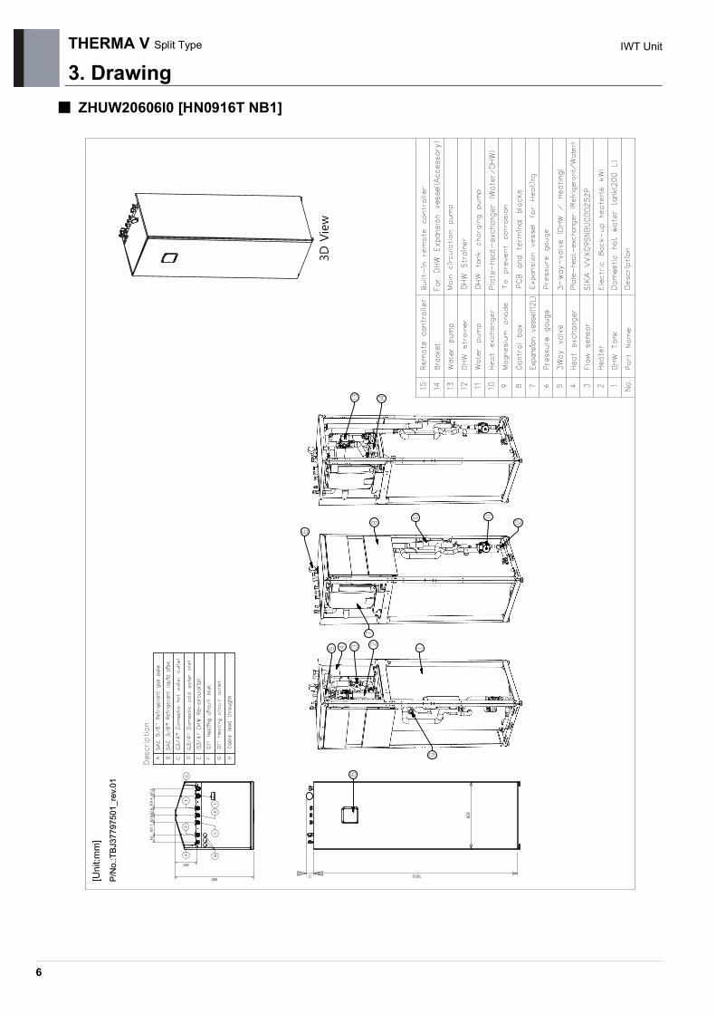
3. Drawing■ ZHUW20606I0 [HN0916T NB1]
P/N
o.:T
BJ37
7975
01_r
ev.0
1P/
No.
:TBJ
3779
7501
_rev
.01
[Uni
t:mm
]

7
THERMA V Split Type IWT Unit
4. Wiring diagrams■ ZHUW20606I0 [HN0916T NB1]

8
THERMA V Split Type IWT Unit
5. Piping diagrams■ ZHNW20606I0 [HN0916T NB1]
Category Symbol Meaning PCB Connector
Refrigerant side
S1 Compressor-suction pipe temperature sensor CN_SUCTIONS2 Inlet IHEX temperature sensor CN_VI_INS3 Outdoor air temperature sensor CN_AIRS4 Outdoor-HEX temp.sensor CN_C_PIPES5 Compressor-discharge pipe temperature sensor CN_DISCHARGES6 Outdoor-HEX middle temp.sensor CN_MIDS9 PHEX gas temp.sensor CN_PIPE/OUTS10 PHEX liquid temp.sensor CN_PIPE/IN
EEV1 Electronic Expansion Valve (Heating) CN_EEV1(WH)EEV3 Electronic Expansion Valve (Injection) CN_EEV1(YL)
Water Side
S11 Inlet water temperature sensorCN_TH3S12 Outlet water temperature sensor
S13 Electric heater outlet sensorS14 DHW tank temperature sensor CN_TH4S17 Flow sensor CN_F_METERA1 Main water pump CN_MOTOR1
CN_W_PUMP_AA16 DHW water pump CN_W_PUMP_BA5 3Way Valve CN_3WAY_AA8 Electric backup heater CN_E_HEAT_A
9
THERMA V Split Type IWT Unit
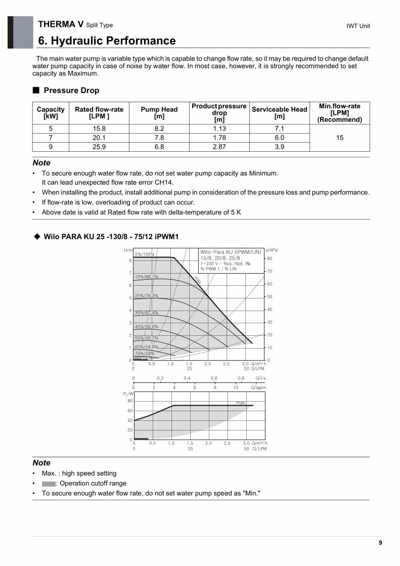
6. Hydraulic PerformanceThe main water pump is variable type which is capable to change flow rate, so it may be required to change default
water pump capacity in case of noise by water flow. In most case, however, it is strongly recommended to set capacity as Maximum.
■ Pressure Drop
Note
• To secure enough water flow rate, do not set water pump capacity as Minimum.It can lead unexpected flow rate error CH14.
• When installing the product, install additional pump in consideration of the pressure loss and pump performance.• If flow-rate is low, overloading of product can occur.• Above date is valid at Rated flow rate with delta-temperature of 5 K
Wilo PARA KU 25 -130/8 - 75/12 iPWM1
Note
• Max. : high speed setting• : Operation cutoff range• To secure enough water flow rate, do not set water pump speed as "Min."
Capacity [kW]
Rated flow-rate [LPM ]
Pump Head[m]
Product pressure drop [m]
Serviceable Head[m]
Min.flow-rate [LPM]
(Recommend)5 15.8 8.2 1.13 7.1
157 20.1 7.8 1.78 6.09 25.9 6.8 2.87 3.9

THERMA V Split Type
6. Hydraulic Performance
10
IWT Unit
The DHW water pump is three speed-adjustable (Maximum / Medium / Minimum), but Minimum step is not used. It is recommended to use Maximum or Medium steps. In case of noise by water flow, it may be required to change default water pump speed. In most case, however, it is strongly recommended to set speed as Maximum.
■ Wilo ZRS 15/6-3 KU
Note
Performance test based on standard ISO 9906 with pre-pressure 2.0bar and liquid temperature 20°C.
WARNING
• Selecting a water flowrate outside the curves can cause damage to or malfunction of the unit.

Outdoor unitTHERMA V
Split Type
1.List of functions2.Specification3.Dimensions4.Wiring Diagram5.Piping Diagram6.Performance Data7.Operation Range8.Electric Characteristics9.Sound Levels
2
THERMA V Split Type Outdoor unit
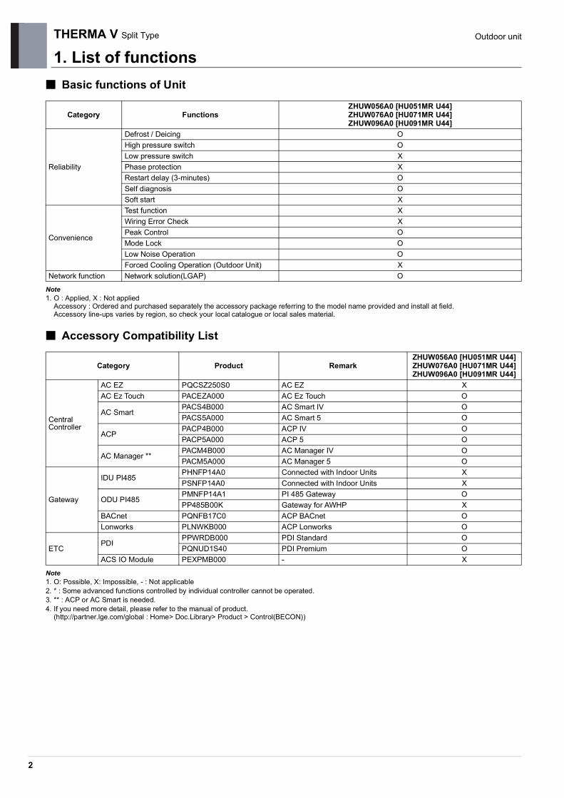
1. List of functions■ Basic functions of Unit
Note1. O : Applied, X : Not applied
Accessory : Ordered and purchased separately the accessory package referring to the model name provided and install at field.Accessory line-ups varies by region, so check your local catalogue or local sales material.
■ Accessory Compatibility List
Note1. O: Possible, X: Impossible, - : Not applicable2. * : Some advanced functions controlled by individual controller cannot be operated.3. ** : ACP or AC Smart is needed.4. If you need more detail, please refer to the manual of product.
(http://partner.lge.com/global : Home> Doc.Library> Product > Control(BECON))
Category FunctionsZHUW056A0 [HU051MR U44]ZHUW076A0 [HU071MR U44]ZHUW096A0 [HU091MR U44]
Reliability
Defrost / Deicing OHigh pressure switch OLow pressure switch XPhase protection XRestart delay (3-minutes) OSelf diagnosis OSoft start X
Convenience
Test function XWiring Error Check XPeak Control OMode Lock OLow Noise Operation OForced Cooling Operation (Outdoor Unit) X
Network function Network solution(LGAP) O
Category Product RemarkZHUW056A0 [HU051MR U44]ZHUW076A0 [HU071MR U44]ZHUW096A0 [HU091MR U44]
Central Controller
AC EZ PQCSZ250S0 AC EZ XAC Ez Touch PACEZA000 AC Ez Touch O
AC SmartPACS4B000 AC Smart IV OPACS5A000 AC Smart 5 O
ACPPACP4B000 ACP IV OPACP5A000 ACP 5 O
AC Manager **PACM4B000 AC Manager IV OPACM5A000 AC Manager 5 O
Gateway
IDU PI485PHNFP14A0 Connected with Indoor Units XPSNFP14A0 Connected with Indoor Units X
ODU PI485PMNFP14A1 PI 485 Gateway OPP485B00K Gateway for AWHP X
BACnet PQNFB17C0 ACP BACnet OLonworks PLNWKB000 ACP Lonworks O
ETCPDI
PPWRDB000 PDI Standard OPQNUD1S40 PDI Premium O
ACS IO Module PEXPMB000 - X

3
THERMA V Split Type Outdoor unit
2. Specifications2.1 Nominal Capacity and Power Input
■ Combination with Hydro Box type
Note1. Due to our policy of innovation some specifications may be changed without notification.2. Wiring cable size must comply with the applicable local and national codes. And “Electric characteristics” chapter should be considered for electrical work and design.
Especially the power cable and circuit breaker should be selected in accordance with that.3. Sound power level is measured on the rated condition in accordance with ISO 9614 standard.
Therefore, these values can be increased owing to ambient conditions during operation.4. Performances are based on the following conditions (It is according to EN14511) :
• Interconnected Pipe Length is standard length and difference of Elevation (Outdoor ~ Indoor Unit) is 0m.5. This product contains Fluorinated greenhouse gases.6. *: These values are accordance with EN14825.7. **:These values are accordance with EN16147.
Nominal Capacity and Nominal Input Indoor unit ZHNW09606A0 [HN0916M NK4]
- Condition Outdoor Temp. (℃) DB / WB
Leaving Water Temp. (℃)
Outdoor Unit
ZHUW056A0 [HU051MR U44]
ZHUW076A0 [HU071MR U44]
ZHUW096A0 [HU091MR U44]
Capacity
Cooling35 / 24 18 kW 5.50 7.00 9.0035 / 24 7 kW 5.50 7.00 9.00
Heating7 / 6 35 kW 5.50 7.00 9.007 / 6 55 kW 5.00 5.50 5.502 / 1 35 kW 3.30 4.20 5.40
Power Input
Cooling35 / 24 18 kW 1.20 1.59 2.1435 / 24 7 kW 1.96 2.59 3.46
Heating7 / 6 35 kW 1.11 1.43 1.947 / 6 55 kW 1.92 1.57 1.572 / 1 35 kW 0.94 1.20 1.54
EER Cooling35 / 24 18 W/W 4.60 4.50 4.2035 / 24 7 W/W 2.80 2.70 2.60
COP Heating7 / 6 35 W/W 4.90 4.90 4.657 / 6 55 W/W 3.50 3.50 3.502 / 1 35 W/W 3.52 3.51 3.50
SCOP (Low temp. Average)* 4.65 4.65 4.46SCOP (High temp. Average)* 3.23 3.23 3.23Rated Water Flow Rate (at LWT 35℃) LPM 15.81 20.12 25.87
Technical SpecificationsIndoor
unit ZHNW09606A0 [HN0916M NK4]
Outdoor Unit
ZHUW056A0 [HU051MR U44]
ZHUW076A0 [HU071MR U44]
ZHUW096A0 [HU091MR U44]
Sound Power Level HeatingRated dB(A) 60 60 60
Low noise dB(A) 58 58 58
DimensionsUnit W × H × D mm 950 × 834 × 330 950 × 834 × 330 950 × 834 × 330Packed Unit W × H × D mm 1,065 × 618 × 461 1,065 × 618 × 461 1,065 × 618 × 461
WeightUnit kg 60.0 60.0 60.0Packed Unit kg 65.0 65.0 65.0
Electrical SpecificationsIndoor
unit ZHNW09606A0 [HN0916M NK4]
Outdoor Unit
ZHUW056A0 [HU051MR U44]
ZHUW076A0 [HU071MR U44]
ZHUW096A0 [HU091MR U44]
Power Supply V, Ø, Hz 220-240, 1, 50 220-240, 1, 50 220-240, 1, 50
Peak Control Running CurrentCooling A 13.0 14.0 15.0Heating A 13.0 14.0 15.0
Rated Running CurrentCooling A 5.3 6.9 9.5Heating A 5.0 6.3 8.6
Circuit breaker A 16 20 25
Wiring ConnectionsPower Supply Cable (H07RN-F)(included Earth)
mm2 x cores 4.0 x 3 4.0 x 3 4.0 x 3

THERMA V Split Type
2. Specifications
4
Outdoor unit
■ Combination with IWT
Note1. Due to our policy of innovation some specifications may be changed without notification.2. Wiring cable size must comply with the applicable local and national codes. And “Electric characteristics” chapter should be considered for electrical work and
design. Especially the power cable and circuit breaker should be selected in accordance with that.3. Sound power level is measured on the rated condition in accordance with ISO 9614 standard.
Therefore, these values can be increased owing to ambient conditions during operation.4. Performances are based on the following conditions (It is according to EN14511) :
• Interconnected Pipe Length is standard length and difference of Elevation (Outdoor ~ Indoor Unit) is 0m.5. This product contains Fluorinated greenhouse gases.6. *: These values are accordance with EN14825.7. **:These values are accordance with EN16147.
Nominal Capacity and Nominal Input Indoor unit ZHNW20606I0 [HN0916T NB1]
- Condition Outdoor Temp. (℃) DB / WB
Leaving Water Temp. (℃)
Outdoor Unit
ZHUW056A0 [HU051MR U44]
ZHUW076A0 [HU071MR U44]
ZHUW096A0 [HU091MR U44]
CapacityCooling 35 / 24 18 kW 5.50 7.00 9.00
Heating7 / 6 35 kW 5.50 7.00 9.007 / 6 55 kW 5.00 5.25 5.50
Power InputCooling 35 / 24 18 kW 1.20 1.59 2.20
Heating7 / 6 35 kW 1.22 1.56 2.057 / 6 55 kW 1.92 2.02 2.12
EER Cooling 35 / 24 18 W/W 4.60 4.40 4.10COP Heating 7 / 6 35 W/W 4.50 4.50 4.40SCOP (Low temp. Average)* 4.52 4.47 4.45SCOP (High temp. Average)* 3.01 3.00 3.03Water Heating Efficiency(profile L)** % 125 125 125Rated Water Flow Rate (at LWT 35℃) LPM 15.81 20.12 25.87
Technical SpecificationsIndoor
unit ZHNW20606I0 [HN0916T NB1]
Outdoor Unit
ZHUW056A0 [HU051MR U44]
ZHUW076A0 [HU071MR U44]
ZHUW096A0 [HU091MR U44]
Sound Power Level HeatingRated dB(A) 60 61 61
Low noise dB(A) 58 58 58
DimensionsUnit W × H × D mm 950 × 834 × 330 950 × 834 × 330 950 × 834 × 330Packed Unit W × H × D mm 1,065 × 618 × 461 1,065 × 618 × 461 1,065 × 618 × 461
WeightUnit kg 60.0 60.0 60.0Packed Unit kg 65.0 65.0 65.0
Electrical SpecificationsIndoor
unit ZHNW20606I0 [HN0916T NB1]
Outdoor Unit
ZHUW056A0 [HU051MR U44]
ZHUW076A0 [HU071MR U44]
ZHUW096A0 [HU091MR U44]
Power Supply V, Ø, Hz 220-240, 1, 50 220-240, 1, 50 220-240, 1, 50
Peak Control Running CurrentCooling A 13.0 14.0 15.0Heating A 13.0 14.0 15.0
Rated Running CurrentCooling A 5.3 6.9 9.5Heating A 5.0 5.3 5.6
Circuit breaker A 16 20 25
Wiring ConnectionsPower Supply Cable (H07RN-F)(included Earth)
mm2 x cores 4.0 x 3 4.0 x 3 4.0 x 3

2. Specifications
5
THERMA V Split Type Outdoor unit
2.2 Outdoor unit
Note
1. Due to our policy of innovation some specifications may be changed without notification.2. Wiring cable size must comply with the applicable local and national codes. And “Electric characteristics” chapter
should be considered for electrical work and design. Especially the power cable and circuit breaker should be selected in accordance with that.
3. Sound power level is measured on the rated condition in according with ISO 9614 standard. Therefore, these values can be increased owing to ambient conditions during operation.
4. Performances are based on the following conditions (It is according to EN14511) :• Interconnected Pipe Length is standard length and difference of Elevation (Outdoor ~ Indoor Unit) is 0m.
5. This product contains Fluorinated greenhouse gases.
Outdoor Units ZHUW056A0 [HU051MR U44]
ZHUW076A0 [HU071MR U44]
ZHUW096A0 [HU091MR U44]
Operation Range (Outdoor Temperature)
Cooling Min. ~ Max. °C DB 5 ~ 48 5 ~ 48 5 ~ 48Heating Min. ~ Max. °C DB -25 ~ 35 -25 ~ 35 -25 ~ 35
Compressor
Type - Hermetic Sealed ScrollModel Model × No. RJB036MAA × 1Motor Type - BLDC BLDC BLDCDisplacement cm3/Rev. 31.6 31.6 31.6
Refrigerant
Type - R32 R32 R32GWP (Global Warming Potential) - 675 675 675Precharged Amount g 1,500 1,500 1,500t-CO2 eq. - 1.013 1.013 1.013Control - Electronic Expansion Valve
Refrigerant OilType - FW68D FW68D FW68DCharged Volume cc × No. 1,100 1,100 1,100
Piping Connections
GasType Flare Flare Flare
mm(Inch) Ф 15.88 (5/8) Ф 15.88 (5/8) Ф 15.88 (5/8)
LiquidType Flare Flare Flare
mm(Inch) Ф 9.52 (3/8) Ф 9.52 (3/8) Ф 9.52 (3/8)
Piping LengthStandard m 5 5 5
Max. m 50 50 50Piping Level Difference Max. m 30 30 30Chargeless-Pipe Length m 10 10 10Additional Charging Volume g/m 30 30 30
Heat Exchanger
Quantity EA 1 1 1
SpecificationRow EA 2 2 2
Column EA 38 38 38FPI EA 14 14 14
FanType - Propeller Propeller PropellerAir Flow Rate Rated m3/min × No. 60.0 × 1 60.0 × 1 60.0 × 1
Fan MotorType - BLDC BLDC BLDCOutput W × No. 124 × 1 124 × 1 124 × 1

6
THERMA V Split Type Outdoor unit
3. Dimensions ZHUW056A0 [HU051MR U44], ZHUW076A0 [HU071MR U44], ZHUW096A0 [HU091MR U44]
Cha
ssis
cod
e : U
4P/
No.
:TBW
3580
6501
_rev
01

7
THERMA V Split Type Outdoor unit
4. Wiring Diagram ZHUW056A0 [HU051MR U44], ZHUW076A0 [HU071MR U44], ZHUW096A0 [HU091MR U44]

8
THERMA V Split Type Outdoor unit
5. Piping Diagram ZHUW056A0 [HU051MR U44], ZHUW076A0 [HU071MR U44], ZHUW096A0 [HU091MR U44]
* This is a piping diagram when combined with hydro box kit. Refer to the indoor unit for the piping diagram of the IWT.
Category Symbol Meaning PCB Connector
Refrigerant side
S1 Compressor-suction pipe temperature sensor CN_SUCTION(GR)S2 Injection EEV discharge temperature sensor CN_VI_IN(WH)S3 Outdoor air temperature sensor CN_AIR(YL)S4 Outdoor-HEX temperature sensor CN_C_PIPE(VI)S5 Compressor-discharge pipe temperature sensor CN_DISCHARGE(BK)S6 Outdoor-HEX middle temperature sensor CN_MID(BR)S9 PHEX gas temperature sensor CN_PIPE_OUT(RD)S10 PHEX liquid temperature sensor CN_PIPE_IN(WH)
EEV1 Electronic Expansion Valve CN_EEV1(WH)EEV3 Electronic Expansion Valve (Injection) CN_EEV3(YL)
Water Side
S11 Inlet water temperature sensor (WATER IN) CN_TH3(BK)S12 Outlet water temperature sensor (PHEX OUT)
S13 Backup heater outlet sensor (WATER OUT)S17 Flow sensor CN_F_METER(BL)A1 Main water pump CN_W_PUMP_A(RD)A8 Electric backup heater (Step1) CN_E_HEAT_A(YL)A9 Electric backup heater (Step 2) CN_E_HEAT_B(VL)
Accumulator
Inv. Com
p
PressureSensor
Muffler
[PHE]
Expansion Tank
Relief valve
PressureGauge
W/Pump S11Strainer
S13
<Water Side><Refrigerant Side>
S6
EEV1
S5S1
S4
EEV3(Inj.EEV)
S2
S10Flow Sensor
Air Vent
PressureSwitch
: Cooling: Heating
S3
WaterOut
WaterIn
p
lve
S9
<Indoor Unit>
Air Vent
S17
S12
A1
A8 / A9
Backup Heater

9
THERMA V Split Type Outdoor unit
6. Performance Data6.1 Cooling Operation
6.1.1 Combination with Hydro Box type
■ Maximum Cooling Capacity
ZHUW056A0 [HU051MR U44] + ZHNW09606A0 [HN0916M NK4]
ZHUW076A0 [HU071MR U44] + ZHNW09606A0 [HN0916M NK4]
ZHUW096A0 [HU091MR U44] + ZHNW09606A0 [HN0916M NK4]
Note1. DB : Dry bulb temperature(℃), LWT : Leaving water temperature(℃), LPM : Liter per minute (ℓ/min)2. TC : Total capacity(kW), COP : Coefficient of performance (kW/kW)3. Direct interpolation is permissible. Do not extrapolate.4. Measuring procedure follows EN14511.
• Rated values are based on standard conditions, and it can be found on specifications.• Above table values may not be matched according to installation condition. Except for rated value, the performance is not guaranteed.• In accordance with the test standard(or nations), the results may vary.
5. The Shaded areas are not guaranteed continuous operation.
Outdoor Temperature
[°C DB]
Water flow rate 15.8 LPMLWT 7 °C LWT 10 °C LWT 13 °C LWT 15 °C LWT 18 °C LWT 20 °C LWT 22 °C
TC COP TC COP TC COP TC COP TC COP TC COP TC COP10 6.42 4.57 6.95 4.85 7.49 5.13 7.85 5.31 8.39 5.59 8.75 5.78 9.11 5.9620 6.05 3.86 6.37 4.23 6.70 4.61 6.91 4.86 7.23 5.23 7.45 5.48 7.66 5.7430 5.68 3.15 5.79 3.62 5.90 4.09 5.97 4.41 6.08 4.88 6.15 5.19 6.22 5.5135 5.50 2.80 5.50 3.32 5.50 3.84 5.50 4.18 5.50 4.60 5.50 5.05 5.50 5.3940 5.32 2.45 5.34 2.84 5.35 3.24 5.37 3.50 5.38 3.90 5.40 4.17 5.41 4.4345 5.13 2.09 5.17 2.37 5.21 2.64 5.23 2.83 5.27 3.10 5.29 3.29 5.32 3.47
Outdoor Temperature
[°C DB]
Water flow rate 20.1 LPMLWT 7 °C LWT 10 °C LWT 13 °C LWT 15 °C LWT 18 °C LWT 20 °C LWT 22 °C
TC COP TC COP TC COP TC COP TC COP TC COP TC COP10 8.17 4.37 8.85 4.64 9.54 4.91 9.99 5.09 10.68 5.35 11.13 5.53 11.59 5.7120 7.70 3.70 8.11 4.06 8.52 4.42 8.80 4.66 9.21 5.01 9.48 5.25 9.75 5.4930 7.23 3.03 7.37 3.48 7.51 3.93 7.60 4.22 7.74 4.67 7.83 4.97 7.92 5.2735 7.00 2.70 7.00 3.19 7.00 3.68 7.00 4.01 7.00 4.50 7.00 4.83 7.00 5.1540 6.77 2.37 6.79 2.74 6.81 3.11 6.83 3.36 6.85 3.74 6.87 3.99 6.88 4.2445 6.53 2.03 6.58 2.29 6.63 2.55 6.66 2.72 6.70 2.98 6.74 3.15 6.77 3.32
Outdoor Temperature
[°C DB]
Water flow rate 25.9 LPMLWT 7 °C LWT 10 °C LWT 13 °C LWT 15 °C LWT 18 °C LWT 20 °C LWT 22 °C
TC COP TC COP TC COP TC COP TC COP TC COP TC COP10 10.50 4.08 11.38 4.33 12.26 4.58 12.85 4.75 13.73 5.00 14.31 5.16 14.90 5.3320 9.90 3.49 10.43 3.81 10.96 4.14 11.31 4.35 11.84 4.68 12.19 4.89 12.54 5.1130 9.30 2.90 9.48 3.30 9.65 3.69 9.77 3.96 9.95 4.36 10.06 4.63 10.18 4.8935 9.00 2.60 9.00 3.04 9.00 3.47 9.00 3.76 9.00 4.20 9.00 4.49 9.00 4.7840 8.70 2.30 8.73 2.63 8.76 2.96 8.78 3.18 8.81 3.50 8.83 3.72 8.85 3.9445 8.40 2.01 8.46 2.23 8.52 2.44 8.56 2.59 8.62 2.81 8.66 2.95 8.70 3.10

THERMA V Split Type
6. Performance Data
10
Outdoor unit
6.1.2 Combination with IWT
ZHUW056A0 [HU051MR U44] + ZHUW20606I0 [HN0916T NB1]
ZHUW076A0 [HU071MR U44] + ZHUW20606I0 [HN0916T NB1]
ZHUW096A0 [HU091MR U44] + ZHUW20606I0 [HN0916T NB1]
Note1. DB : Dry bulb temperature(℃), LWT : Leaving water temperature(℃), LPM : Liter per minute (ℓ/min)2. TC : Total capacity(kW), COP : Coefficient of performance (kW/kW)3. Direct interpolation is permissible. Do not extrapolate.4. Measuring procedure follows EN14511.
• Rated values are based on standard conditions, and it can be found on specifications.• Above table values may not be matched according to installation condition. Except for rated value, the performance is not guaranteed.• In accordance with the test standard(or nations), the results may vary.
5. The Shaded areas are not guaranteed continuous operation.
Outdoor Temperature
[°C DB]
Water flow rate 15.8 LPMLWT 7 °C LWT 10 °C LWT 13 °C LWT 15 °C LWT 18 °C LWT 20 °C LWT 22 °C
TC COP TC COP TC COP TC COP TC COP TC COP TC COP10 6.42 4.47 6.95 4.74 7.49 5.02 7.85 5.20 8.39 5.47 8.75 5.66 9.11 5.8420 6.05 3.80 6.37 4.16 6.70 4.52 6.91 4.76 7.23 5.12 7.45 5.36 7.66 5.6030 5.68 3.13 5.79 3.58 5.90 4.03 5.97 4.33 6.08 4.77 6.15 5.07 6.22 5.3735 5.50 2.80 5.50 3.29 5.50 3.78 5.50 4.11 5.50 4.60 5.50 4.93 5.50 5.2540 5.32 2.47 5.34 2.84 5.35 3.21 5.37 3.46 5.38 3.83 5.40 4.08 5.41 4.3245 5.13 2.13 5.17 2.39 5.21 2.64 5.23 2.81 5.27 3.06 5.29 3.23 5.32 3.40
Outdoor Temperature
[°C DB]
Water flow rate 20.1 LPMLWT 7 °C LWT 10 °C LWT 13 °C LWT 15 °C LWT 18 °C LWT 20 °C LWT 22 °C
TC COP TC COP TC COP TC COP TC COP TC COP TC COP10 8.17 4.27 8.85 4.54 9.54 4.80 9.99 4.97 10.68 5.23 11.13 5.41 11.59 5.5820 7.70 3.62 8.11 3.97 8.52 4.32 8.80 4.55 9.21 4.90 9.48 5.13 9.75 5.3730 7.23 2.97 7.37 3.40 7.51 3.84 7.60 4.13 7.74 4.57 7.83 4.86 7.92 5.1535 7.00 2.64 7.00 3.12 7.00 3.60 7.00 3.92 7.00 4.40 7.00 4.72 7.00 5.0440 6.77 2.31 6.79 2.68 6.81 3.05 6.83 3.29 6.85 3.66 6.87 3.90 6.88 4.1445 6.53 1.99 6.58 2.24 6.63 2.49 6.66 2.66 6.70 2.91 6.74 3.08 6.77 3.25
Outdoor Temperature
[°C DB]
Water flow rate 25.9 LPMLWT 7 °C LWT 10 °C LWT 13 °C LWT 15 °C LWT 18 °C LWT 20 °C LWT 22 °C
TC COP TC COP TC COP TC COP TC COP TC COP TC COP10 10.50 3.98 11.38 4.23 12.26 4.47 12.85 4.63 13.73 4.88 14.31 5.04 14.90 5.2020 9.90 3.40 10.43 3.72 10.96 4.04 11.31 4.25 11.84 4.57 12.19 4.78 12.54 4.9930 9.30 2.83 9.48 3.22 9.65 3.61 9.77 3.87 9.95 4.26 10.06 4.52 10.18 4.7735 9.00 2.54 9.00 2.96 9.00 3.39 9.00 3.67 9.00 4.10 9.00 4.38 9.00 4.6740 8.70 2.25 8.73 2.57 8.76 2.89 8.78 3.10 8.81 3.42 8.83 3.63 8.85 3.8545 8.40 1.96 8.46 2.17 8.52 2.39 8.56 2.53 8.62 2.74 8.66 2.88 8.70 3.03

6. Performance Data
11
THERMA V Split Type Outdoor unit
6.2 Heating Operation
6.2.1 Combination with Hydro Box type
■ Maximum Heating Capacity (Include defrost effect)
ZHUW056A0 [HU051MR U44] + ZHNW09606A0 [HN0916M NK4]
ZHUW076A0 [HU071MR U44] + ZHNW09606A0 [HN0916M NK4]
ZHUW096A0 [HU091MR U44] + ZHNW09606A0 [HN0916M NK4]
Note1. DB : Dry bulb temperature(℃), LWT : Leaving water temperature(℃), LPM : Liter per minute (ℓ/min)2. TC : Total capacity(kW), COP : Coefficient of performance (kW/kW)3. Direct interpolation is permissible. Do not extrapolate.4. Measuring procedure follows EN14511.
• Rated values are based on standard conditions, and it can be found on specifications.• Above table values may not be matched according to installation condition. Except for rated value, the performance is not guaranteed.• In accordance with the test standard(or nations), the results may vary.
5. The Shaded areas are not guaranteed continuous operation.
Outdoor Temperature
[°C DB]
Water flow rate 15.8 LPM Water flow rate 9.9 LPM Water flow rate 7.9 LPMLWT 30 °C LWT 35 °C LWT 40 °C LWT 45 °C LWT 50 °C LWT 55 °C LWT 60 °C LWT 65 °CTC COP TC COP TC COP TC COP TC COP TC COP TC COP TC COP
-25 4.02 1.96 3.90 1.84 3.78 1.72 3.66 1.60 -20 4.64 2.59 4.51 2.07 4.38 1.90 4.26 1.74 4.13 1.57 -15 5.26 2.51 5.12 2.30 4.99 2.09 4.85 1.88 4.72 1.66 4.58 1.45 -7 5.50 2.88 5.50 2.70 5.50 2.53 5.50 2.35 5.50 2.18 5.50 2.00 5.50 1.83 -4 5.50 3.18 5.50 2.97 5.50 2.75 5.50 2.53 5.50 2.31 5.50 2.10 5.50 1.88 -2 5.50 3.41 5.50 3.14 5.50 2.88 5.50 2.61 5.50 2.34 5.50 2.08 5.50 1.81 2 5.50 3.79 5.50 3.50 5.50 3.21 5.50 2.93 5.50 2.64 5.50 2.36 5.50 2.07 5.50 1.797 5.50 5.37 5.50 4.90 5.50 4.43 5.50 3.97 5.50 3.50 5.50 3.03 5.50 2.57 5.50 2.1010 5.50 5.84 5.50 5.34 5.50 4.83 5.50 4.32 5.50 3.81 5.50 3.30 5.50 2.79 5.50 2.2915 5.50 6.64 5.50 6.06 5.50 5.48 5.50 4.91 5.50 4.33 5.50 3.75 5.50 3.17 5.50 2.6018 5.50 7.11 5.50 6.50 5.50 5.88 5.50 5.26 5.50 4.64 5.50 4.02 5.50 3.40 5.50 2.7820 5.50 7.43 5.50 6.79 5.50 6.14 5.50 5.49 5.50 4.85 5.50 4.20 5.50 3.55 5.50 2.9135 5.50 9.81 5.50 8.96 5.50 8.11 5.50 7.25 5.50 6.40 5.50 5.55 5.50 4.69 5.50 3.84
Outdoor Temperature
[°C DB]
Water flow rate 20.1 LPM Water flow rate 12.6 LPM Water flow rate 10.0 LPMLWT 30 °C LWT 35 °C LWT 40 °C LWT 45 °C LWT 50 °C LWT 55 °C LWT 60 °C LWT 65 °CTC COP TC COP TC COP TC COP TC COP TC COP TC COP TC COP
-25 5.00 1.95 4.85 1.78 4.71 1.62 4.56 1.45 -20 5.58 2.52 5.43 2.02 5.27 1.84 5.11 1.66 4.95 1.49 -15 6.17 2.44 6.00 2.25 5.83 2.06 5.66 1.88 5.49 1.69 5.32 1.50 -7 7.00 2.76 7.00 2.72 7.00 2.44 7.00 2.28 7.00 2.11 7.00 2.06 7.00 1.79 -4 7.00 3.07 7.00 2.87 7.00 2.66 7.00 2.45 7.00 2.24 7.00 2.08 7.00 1.83 -2 7.00 3.27 7.00 3.04 7.00 2.82 7.00 2.59 7.00 2.37 7.00 2.14 7.00 2.06 2 7.00 3.65 7.00 3.40 7.00 3.15 7.00 2.90 7.00 2.66 7.00 2.41 7.00 2.16 7.00 1.917 7.00 5.35 7.00 4.90 7.00 4.45 7.00 4.00 7.00 3.55 7.00 3.10 7.00 2.65 7.00 2.2010 7.00 5.77 7.00 5.28 7.00 4.80 7.00 4.31 7.00 3.83 7.00 3.34 7.00 2.86 7.00 2.3715 7.00 6.46 7.00 5.92 7.00 5.37 7.00 4.83 7.00 4.29 7.00 3.74 7.00 3.20 7.00 2.6618 7.00 6.88 7.00 6.30 7.00 5.72 7.00 5.14 7.00 4.56 7.00 3.99 7.00 3.41 7.00 2.8320 7.00 7.16 7.00 6.55 7.00 5.95 7.00 5.35 7.00 4.75 7.00 4.15 7.00 3.54 7.00 2.9435 7.00 9.24 7.00 8.46 7.00 7.69 7.00 6.91 7.00 6.13 7.00 5.35 7.00 4.58 7.00 3.80
Outdoor Temperature
[°C DB]
Water flow rate 25.9 LPM Water flow rate 16.2 LPM Water flow rate 12.9 LPMLWT 30 °C LWT 35 °C LWT 40 °C LWT 45 °C LWT 50 °C LWT 55 °C LWT 60 °C LWT 65 °CTC COP TC COP TC COP TC COP TC COP TC COP TC COP TC COP
-25 6.40 1.85 6.20 1.70 6.00 1.55 5.80 1.40 -20 7.23 2.45 7.00 1.96 6.77 1.80 6.54 1.64 6.31 1.48 -15 8.06 2.39 7.80 2.22 7.54 2.05 7.28 1.89 7.02 1.72 6.76 1.55 -7 9.00 2.75 9.00 2.71 9.00 2.35 9.00 2.20 9.00 2.05 9.00 1.90 9.00 1.75 -4 9.00 2.98 9.00 2.78 9.00 2.58 9.00 2.38 9.00 2.18 9.00 1.98 9.00 1.78 -2 9.00 3.16 9.00 2.97 9.00 2.78 9.00 2.59 9.00 2.40 9.00 2.21 9.00 2.02 2 9.00 3.57 9.00 3.35 9.00 3.13 9.00 2.91 9.00 2.69 9.00 2.47 9.00 2.25 9.00 2.047 9.00 5.04 9.00 4.65 9.00 4.26 9.00 3.87 9.00 3.48 9.00 3.08 9.00 2.69 9.00 2.3010 9.00 5.39 9.00 4.97 9.00 4.55 9.00 4.13 9.00 3.71 9.00 3.30 9.00 2.88 9.00 2.4615 9.00 5.97 9.00 5.50 9.00 5.04 9.00 4.58 9.00 4.11 9.00 3.65 9.00 3.19 9.00 2.7218 9.00 6.32 9.00 5.83 9.00 5.33 9.00 4.84 9.00 4.35 9.00 3.86 9.00 3.37 9.00 2.8820 9.00 6.55 9.00 6.04 9.00 5.53 9.00 5.02 9.00 4.51 9.00 4.00 9.00 3.50 9.00 2.9935 9.00 8.29 9.00 7.64 9.00 7.00 9.00 6.35 9.00 5.71 9.00 5.07 9.00 4.42 9.00 3.78

THERMA V Split Type
6. Performance Data
12
Outdoor unit
6.2.2 Combination with IWT
■ Maximum Heating Capacity (Include defrost effect)
ZHUW056A0 [HU051MR U44] + ZHUW20606I0 [HN0916T NB1]
ZHUW076A0 [HU071MR U44] + ZHUW20606I0 [HN0916T NB1]
ZHUW096A0 [HU091MR U44] + ZHUW20606I0 [HN0916T NB1]
Note1. DB : Dry bulb temperature(℃), LWT : Leaving water temperature(℃), LPM : Liter per minute (ℓ/min)2. TC : Total capacity(kW), COP : Coefficient of performance (kW/kW)3. Direct interpolation is permissible. Do not extrapolate.4. Measuring procedure follows EN14511.
• Rated values are based on standard conditions, and it can be found on specifications.• Above table values may not be matched according to installation condition. Except for rated value, the performance is not guaranteed.• In accordance with the test standard(or nations), the results may vary.
5. The Shaded areas are not guaranteed continuous operation.
Outdoor Temperature
[°C DB]
Water flow rate 15.8 LPM Water flow rate 9.9 LPM Water flow rate 7.9 LPMLWT 30 °C LWT 35 °C LWT 40 °C LWT 45 °C LWT 50 °C LWT 55 °C LWT 60 °C LWT 65 °CTC COP TC COP TC COP TC COP TC COP TC COP TC COP TC COP
-25 4.02 1.83 3.90 1.68 3.78 1.53 3.66 1.38 -20 4.64 1.99 4.51 1.84 4.38 1.69 4.26 1.53 4.13 1.38 -15 5.26 2.16 5.12 2.00 4.99 1.84 4.85 1.69 4.72 1.53 4.58 1.39 -7 5.50 2.88 5.50 2.65 5.50 2.42 5.50 2.19 5.50 1.96 5.50 1.73 5.50 1.50 -4 5.50 3.06 5.50 2.84 5.50 2.62 5.50 2.39 5.50 2.17 5.50 1.95 5.50 1.73-2 5.50 3.15 5.50 2.96 5.50 2.78 5.50 2.59 5.50 2.40 5.50 2.21 5.50 2.022 5.50 3.43 5.50 3.21 5.50 3.00 5.50 2.79 5.50 2.57 5.50 2.36 5.50 2.15 5.50 1.947 5.50 4.91 5.50 4.50 5.50 4.09 5.50 3.69 5.50 3.28 5.50 2.87 5.50 2.47 5.50 2.0610 5.50 5.09 5.50 4.66 5.50 4.24 5.50 3.82 5.50 3.40 5.50 2.98 5.50 2.56 5.50 2.1415 5.50 5.38 5.50 4.94 5.50 4.49 5.50 4.04 5.50 3.60 5.50 3.15 5.50 2.71 5.50 2.2618 5.50 5.56 5.50 5.10 5.50 4.64 5.50 4.18 5.50 3.72 5.50 3.26 5.50 2.80 5.50 2.3420 5.50 5.68 5.50 5.21 5.50 4.74 5.50 4.27 5.50 3.80 5.50 3.33 5.50 2.86 5.50 2.3935 5.50 6.57 5.50 6.03 5.50 5.48 5.50 4.94 5.50 4.39 5.50 3.85 5.50 3.30 5.50 2.76
Outdoor Temperature
[°C DB]
Water flow rate 20.1 LPM Water flow rate 12.6 LPM Water flow rate 10.0 LPMLWT 30 °C LWT 35 °C LWT 40 °C LWT 45 °C LWT 50 °C LWT 55 °C LWT 60 °C LWT 65 °CTC COP TC COP TC COP TC COP TC COP TC COP TC COP TC COP
-25 5.00 1.77 4.85 1.62 4.71 1.47 4.56 1.32 -20 5.58 2.04 5.43 1.80 5.27 1.64 5.11 1.49 4.95 1.34 -15 6.17 2.13 6.00 1.97 5.83 1.82 5.66 1.66 5.49 1.51 5.32 1.35 -7 7.00 2.83 7.00 2.61 7.00 2.39 7.00 2.17 7.00 1.94 7.00 1.72 7.00 1.50 -4 7.00 2.99 7.00 2.78 7.00 2.57 7.00 2.36 7.00 2.16 7.00 1.95 7.00 1.74-2 7.00 3.07 7.00 2.89 7.00 2.72 7.00 2.55 7.00 2.37 7.00 2.20 7.00 2.022 7.00 3.31 7.00 3.12 7.00 2.93 7.00 2.74 7.00 2.55 7.00 2.36 7.00 2.17 7.00 1.987 7.00 4.89 7.00 4.50 7.00 4.11 7.00 3.72 7.00 3.33 7.00 2.93 7.00 2.54 7.00 2.1510 7.00 5.12 7.00 4.71 7.00 4.30 7.00 3.89 7.00 3.48 7.00 3.07 7.00 2.66 7.00 2.2515 7.00 5.50 7.00 5.06 7.00 4.62 7.00 4.18 7.00 3.74 7.00 3.30 7.00 2.86 7.00 2.4218 7.00 5.73 7.00 5.27 7.00 4.81 7.00 4.36 7.00 3.90 7.00 3.44 7.00 2.98 7.00 2.5220 7.00 5.88 7.00 5.41 7.00 4.94 7.00 4.47 7.00 4.00 7.00 3.53 7.00 3.06 7.00 2.5935 7.00 7.03 7.00 6.47 7.00 5.90 7.00 5.34 7.00 4.78 7.00 4.22 7.00 3.65 7.00 3.09
Outdoor Temperature
[°C DB]
Water flow rate 25.9 LPM Water flow rate 16.2 LPM Water flow rate 12.9 LPMLWT 30 °C LWT 35 °C LWT 40 °C LWT 45 °C LWT 50 °C LWT 55 °C LWT 60 °C LWT 65 °CTC COP TC COP TC COP TC COP TC COP TC COP TC COP TC COP
-25 6.40 1.71 6.20 1.56 6.00 1.41 5.80 1.26 -20 7.23 1.99 7.00 1.72 6.77 1.56 6.54 1.41 6.31 1.26 -15 8.06 2.03 7.80 1.87 7.54 1.72 7.28 1.56 7.02 1.41 6.76 1.27 -7 9.00 2.74 9.00 2.52 9.00 2.30 9.00 2.08 9.00 1.85 9.00 1.63 9.00 1.41 -4 9.00 2.94 9.00 2.74 9.00 2.54 9.00 2.34 9.00 2.14 9.00 1.94 9.00 1.74-2 9.00 3.05 9.00 2.88 9.00 2.71 9.00 2.54 9.00 2.36 9.00 2.19 9.00 2.022 9.00 3.36 9.00 3.17 9.00 2.98 9.00 2.79 9.00 2.60 9.00 2.40 9.00 2.217 9.00 4.76 9.00 4.40 9.00 4.04 9.00 3.68 9.00 3.32 9.00 2.96 9.00 2.6010 9.00 5.04 9.00 4.66 9.00 4.28 9.00 3.89 9.00 3.51 9.00 3.13 9.00 2.75 9.00 2.3715 9.00 5.50 9.00 5.08 9.00 4.67 9.00 4.25 9.00 3.84 9.00 3.42 9.00 3.00 9.00 2.5918 9.00 5.78 9.00 5.34 9.00 4.90 9.00 4.47 9.00 4.03 9.00 3.59 9.00 3.16 9.00 2.7220 9.00 5.96 9.00 5.51 9.00 5.06 9.00 4.61 9.00 4.16 9.00 3.71 9.00 3.26 9.00 2.8135 9.00 7.35 9.00 6.80 9.00 6.24 9.00 5.68 9.00 5.13 9.00 4.57 9.00 4.02 9.00 3.46

13
THERMA V Split Type Outdoor unit
7. Operation Range■ Cooling
Note• Continuous Operation : It is possible to operate continuously, but capacity is not guaranteed.• Operative : It is not guaranteed continuous operation.
Continuous Operation Operative
Cooling(Settings : Outlet temp. control / Fan coil unit used)
10
46
48
5
Leaving Water Temperature( )
Out
door
Tem
pera
ture
()
275
Cooling(Settings : Inlet temp. control / Fan coil unit used)
27
10
46
48
10
Entering Water Temperature( )O
utdo
or T
empe
ratu
re(
)
5
Continuous Operation Operative
Cooling(Settings : Outlet temp. control / Fan coil unit not used)
27
46
48
16Leaving Water Temperature( )
Out
door
Tem
pera
ture
()
10
5
Continuous Operation Operative
Cooling(Settings : Inlet temp. control / Fan coil unit not used)
27
46
48
20
Entering Water Temperature( )
Out
door
Tem
pera
ture
()
10
5
Continuous Operation Operative

THERMA V Split Type
7. Operation Range
14
Outdoor unit
■ Heating
Note
• Continuous Operation : It is possible to operate continuously, but capacity is not guaranteed.• Operative : It is not guaranteed continuous operation.• DHW operation : max. 58 °C• DHW operation with Electric heater : max. 80 °C
Heating
Continuous Operation
Operative
8065554825
-25
-15
7
20
35
15
Leaving Water Temperature( )
Out
door
Tem
pera
ture
()
0
40
Electric operation only (DHW)
Electric heater required to achieve temp.
(Setting : Outlet temp. control)
60
Operative(IWT only)
Heating
Continuous Operation
Operative
Entering Water Temperature ( )
Out
door
Tem
pera
ture
()
Electric operation only (DHW)
Electric requiredto achieve temp.8055
-25
-15
7
35
20
0
40 4715
(Setting : Inlet temp. control)
Operative(IWT only)
20
50

15
THERMA V Split Type Outdoor unit
8. Electric characteristics■ Wiring of Main Power Supply and Equipment Capacity1. Use a separate power supply for the Outdoor Unit and Backup Heater.2. Bear in mind ambient conditions (ambient temperature,direct sunlight, rain liquid,etc.) when proceeding with the
wiring and connections3. The wire size is the minimum value for metal conduit wiring. The power cord size should be 1 rank thicker taking
into account the line voltage drops. Make sure the power-supply voltage does not drop more than 10%.4. Specific wiring requirements should adhere to the wiring regulations of the region.5. Power supply cords of parts of appliances for outdoor use should not be lighter than polychloroprene sheathed
flexible cord.6. Don't install an individual switch or electrical outlet to disconnect the indoor unit separately from the power
supply.
WARNING
• Follow ordinance of your governmental organization for technical standard related to electrical equipment, wiring regulations and guidance of each electric power company.
• Make sure to use specified wires for connections so that no external force is imparted to terminal connections. If connections are not fixed firmly, it may cause heating or fire.
• Make sure to use the appropriate type of overcurrent protection switch. Note that generated overcurrent may include some amount of direct current.
CAUTION
• All installation site must require attachment of an earth leakage breaker. If no earth leakage breaker is installed, it may cause an electric shock.
• Do not use anything other than breaker and fuse with correct capacity. Using fuse and wire or copper wire with too large capacity may cause a malfunction of unit or fire.

THERMA V Split Type
8. Electric characteristics
16
Outdoor unit
■ Outdoor Unit and Hydro Box Unit
Note1. Voltage supplied to the unit terminals should be within the minimum and maximum range.2. Maximum allowable voltage unbalance between phase is 2%.3. All installation site must require attachment of an earth leakage breaker. [circuit breaker type is ELCB(Earth Leakage Circuit Breaker)].
Model Built-In Electric HeaterIndoor Unit Outdoor Unit Phase / Volts / Hz Capacity (kW) Phase / Volts
ZHNW09606A0[HN0916M Nk4]
ZHUW056A0 [HU051MR U44]
1 / 220-240V / 50Hz 3 + 3 1 / 220-240 VZHUW076A0[HU071MR U44]
ZHUW096A0[HU091MR U44]
DHW Boost Heater Indoor Unit
Power Supply for DHW Boost HeaterPhase / Volts / Hz Capacity (kW)
Integral part of DHW tanks[OSHW-x00F(D)] 1 Ø / 220-240 V / 50 Hz 2.4
[Power Supply for Heat Pump]
[Power Supply for Backup Heater]
[Power Supply for DHW Boost Heater]
ELCB CB
Outdoor Unit
Indoor Unit
Power SourceCommunication
Switch Box
Power SourceCommunication
Switch Box
ELCB CB
Outdoor Unit
Indoor Unit
CB
CommunicationPower Source
Switch Box
ELCB CB
Outdoor Unit
UnitIndoor
Sensor
CB
DHW Tank kit
DHWTank

8. Electric characteristics
17
THERMA V Split Type Outdoor unit
■ IWT Unit
Note1. Voltage supplied to the unit terminals should be within the minimum and maximum range.2. Maximum allowable voltage unbalance between phase is 2%.3. All installation site must require attachment of an earth leakage breaker. [circuit breaker type is ELCB(Earth Leakage Circuit Breaker)].4. *The capacity of Electrical Heater depend on the choice of the connection power.
Model Built-In Electric HeaterIndoor Unit Outdoor Unit Phase / Volts / Hz Capacity(kW)*
ZHNW20606I0[HN0916T NB1]
ZHUW056A0 [HU051MR U44]
1 / 220-240V / 50Hz
1Ø 2 (2)
1Ø 4 (2+2)
3Ø 6 (2+2+2)
ZHUW076A0[HU071MR U44]
ZHUW096A0[HU091MR U44]
[Power Supply for 1Ф Electric heater]
[Power Supply for 3Ф Electric heater]

18
THERMA V Split Type Outdoor unit
9. Sound levels9.1 Sound power levelNote
1. Data is valid at diffuse field condition.2. Reference acoustic intensity 0dB = 10E-6μW/m2
3. Sound power level is measured on the rated condition in the reverberation rooms. Refer to the Model Specifications for nominal conditions(Power source and Ambient temperature, etc)
4. Sound levels can be increased in accordance with installation and operating conditions.5. Sound level will vary depending on a range of factors such as the construction (acoustic absorption coefficient)
of particular installed place in which the equipment in installed.6. Sound power level is measured on the rated condition in accordance with ISO 9614 standard.
Therefore, these values can be increased owing to ambient conditions during operation.
Model Sound Power Level [dB(A)]Heating
Indoor Unit Outdoor Unit Rated Low Noise
ZHNW09606A0 [HN0916M NK4]ZHUW056A0 [HU051MR U44] 60 58ZHUW076A0 [HU071MR U44] 60 58ZHUW096A0 [HU091MR U44] 60 58
10
20
30
40
50
60
70
80
90
100
110
120
125 250 500 1000 2000 4000 8000
NR-70
NR-65
Soun
d Po
wer
Lev
el (0
dB =
10E
-6μW
/m2
)
NR-60
NR-55
NR-50
NR-45
Octave Band Center Frequency (Hz)
NR-40
NR-35
NR-30
NR-75
NR-25
NR-20
NR-80
NR-85
NR-90
RatedLow Noise
NR-95
NR-100
NR-105
NR-110
NR-115

9. Sound levels
19
THERMA V Split Type Outdoor unit
Note
1. Data is valid at diffuse field condition.2. Reference acoustic intensity 0dB = 10E-6μW/m2
3. Sound power level is measured on the rated condition in the reverberation rooms. Refer to the Model Specifications for nominal conditions(Power source and Ambient temperature, etc)
4. Sound levels can be increased in accordance with installation and operating conditions.5. Sound level will vary depending on a range of factors such as the construction (acoustic absorption coefficient)
of particular installed place in which the equipment in installed.6. Sound power level is measured on the rated condition in accordance with ISO 9614 standard.
Therefore, these values can be increased owing to ambient conditions during operation.
Model Sound Power Level [dB(A)]Heating
Indoor Unit Outdoor Unit Rated Low Noise
ZHNW20606I0 [HN0916T NB1]ZHUW056A0 [HU051MR U44] 60 58ZHUW076A0 [HU071MR U44] 61 58ZHUW096A0 [HU091MR U44] 61 58
ZHUW056A0 [HU051MR U44] ZHUW076A0 [HU071MR U44] ZHUW096A0 [HU091MR U44]
10.0
20.0
30.0
40.0
50.0
60.0
70.0
80.0
90.0
100.0
110.0
120.0
125 250 500 1000 2000 4000 8000
Soun
d Po
wer
Lev
el (0
dB =
10E
-6μW
/m2
)
Octave Band Center Frequency (Hz)
NR-70
NR-65
NR-60
NR-55
NR-50
NR-45
NR-40
NR-35
NR-30
NR-75
NR-25
NR-20
NR-80
NR-85
NR-90
RatedLow Noise
NR-95
NR-100
NR-105
NR-110

Design and installationTHERMA V
Split Type
1.Refrigerant R322.Select the Best Location3.Installation Space4.Water Control5.Dip Switch Setting

2
THERMA V Split Type Design and installation
1. Refrigerant R32The refrigerant R32 has the higher efficiency and more friendly for environment in comparison with R410A. It has
a lower GWP (Global Warming Potential) value, and higher efficiency than R410A. The Ozone Depletion Potential (ODP) of R32 is 0, and Global Warming Potential(GWP) is 675.
Refrigerant piping consists of copper/steel pipes, joints, and other fittings. All components must be selected and installed in conformity with the standards pertaining to the Refrigeration Safety Regulation. Same piping as for R410A can be used.
WARNING
• This product contains fluorinated greenhouse gases (Refrigerant type : R32). Do NOT emit refrigerant gases into the atmosphere.
• The refrigerant R32 is Slightly Flammable gas. But it does not leak normally. If the refrigerant leaks in the installed place and contact with burning energy, it may cause fire, or a harmful gas.
• If there are some leak, turn off any combustible devices, ventilate the installed place, and contact the dealer from which you purchased the unit. Do not use the unit until the refrigerant leaked is repaired.
• Only use R32 as refrigerant. Other substances may cause explosions and accidents.
CAUTION
• The wall thickness of the piping should comply with the relevant local and national regulations for the designed pressure.
• For high-pressure refrigerant, any unapproved pipe must not be used.• Do not heat pipes more than necessary to prevent them from softening.
3
THERMA V Split Type Design and installation
2. Select the Best LocationSelect space for installing unit, which will meet the following conditions:
• No direct thermal radiation from other heat sources• No possibility of annoying neighbors by noise from unit• No exposition to strong wind• With strength which bears weight of unit• With space for air passage and service work shown next• Because of the possibility of fire, do not install unit to the space where generation, inflow, stagnation, and
leakage of combustible gas is expected.• Avoid unit installation in a place where acidic solution and spray (sulfur) are often used.• Do not use unit under any special environment where oil, steam and sulfuric gas exist.• It is recommended to fence round the unit in order to prevent any person or animal from accessing the unit.• If installation site is area of heavy snowfall, then the following directions should be observed.
– Make the foundation as high as possible.– Fit a snow protection hood.
• Select installation location considering following conditions to avoid bad condition when additionally performing defrost operation.1. Install the unit at a place well ventilated and having a lot of sunshine in case of installing the product at a place
with a high humidity in winter (near beach, coast, lake, etc).2. Performance of heating will be reduced and pre-heat time of the unit may be lengthened in case of installing
the unit in winter at following location:1) Shade position with a narrow space2) Location with much humidity around.3) Location where liquid gathers since the floor is not even.
• When installing the unit in a place that is constantly exposed to a strong wind like a coast or on a high story of a building, secure a normal fan operation by using a duct or a wind shield.1. Install the unit so that its discharge port faces to the wall of the building. Keep a distance 300 mm or more
between the unit and the wall surface.2. Supposing the wind direction during the operation season of the unit, install the unit so that the discharge port
is set at right angle to the wind direction.

4
THERMA V Split Type Design and installation
3. Installation Space3.1 Clearance around outdoor units• Ensure that the space around the back is
or more more than 300 mm on the opposite to the PCB side and secure 600 mm space near the compressor and PCB side of the air conditioner for service.
• Install the unit so that its discharge port faces to the wall of the building. Keep a distance 500mm or more between the unit and the wall surface.
• Supposing the wind direction during the operation season of the air conditioner, install the unit so that the discharge port is set at right angle to the wind direction.
※ Outdoor unit is representative. Actual appearance of outdoor unit may bedifferent but clearances will stay the same.
300 mm or more
es
700 mmor more
300 mmor more
obsFence ortacl
600 mmor more (Service space)
Sunroof300 mm or more
300 mm or more
Air inlet grille500 mm
Strongwind
Strongwind
Blown air
※ Outdoor unit is representative. Actual appearance of outdoor unit may bedifferent but clearances will stay the same.
Set the outlet side at a right angleto the direction of the wind.
Turn the air outlet side toward the building'swall, fence or windbreak screen.

5
THERMA V Split Type Design and installation
4. Water Control4.1 Water quality
Water quality should be complied with EN 98/83 EC Directives.
CAUTION
• If the product is installed at existing hydraulic water loop, it is important to clean hydraulic pipes to remove sludge and scale.
• Installing sludge strainer in the water loop is very important to prevent performance degrade.• Chemical treatment to prevent rust should be performed by installer.• It is strongly recommended to install an additional filter on the heating water circuit. Especially to remove metallic
particles from the heating piping, it is advised to use a magnetic or cyclone filter, which can remove small particles. Small particles may damage the unit and will NOT be removed by the standard filter of the heat pump system.
• Water quality check should be implemented before completing the installation of system.Detailed guide can be found in the table as below.
Water contents ValuepH 7.5~9.0Conductivity 10~500 uS/cmTDS (Total dissolved solids) 8~400 ppmAlkalinity (HCO3
-) 60~300 (mg/L)
Total hardness4 ~ 8.5 ºdH
71.4 ~ 151.7 (mg/L)Iron (Fe) ≤ 0.2 (mg/L)Sulphate (SO4
2-) ≤ 100 (mg/L)
Nitrite (NO3-) ≤ 100 (mg/L)
Free chlorine (Cl2) ≤ 1 (mg/L)
Chlorides (Cl-)
ppm STS316 STS304
pH7
15℃ 3,000 18040℃ 500 5060℃ 200 3080℃ 125 20
pH9
15℃ 18,000 70040℃ 2,600 25060℃ 1,000 17080℃ 550 130
THERMA V Split Type
4. Water Control
6
Design and installation
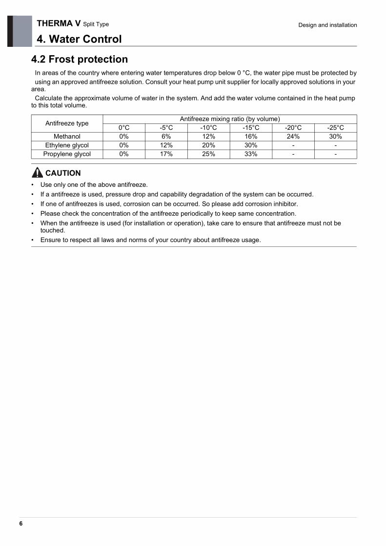
4.2 Frost protectionIn areas of the country where entering water temperatures drop below 0 °C, the water pipe must be protected byusing an approved antifreeze solution. Consult your heat pump unit supplier for locally approved solutions in your
area.Calculate the approximate volume of water in the system. And add the water volume contained in the heat pump
to this total volume.
CAUTION
• Use only one of the above antifreeze.• If a antifreeze is used, pressure drop and capability degradation of the system can be occurred.• If one of antifreezes is used, corrosion can be occurred. So please add corrosion inhibitor.• Please check the concentration of the antifreeze periodically to keep same concentration.• When the antifreeze is used (for installation or operation), take care to ensure that antifreeze must not be
touched.• Ensure to respect all laws and norms of your country about antifreeze usage.
Antifreeze type Antifreeze mixing ratio (by volume)0°C -5°C -10°C -15°C -20°C -25°C
Methanol 0% 6% 12% 16% 24% 30%Ethylene glycol 0% 12% 20% 30% - -
Propylene glycol 0% 17% 25% 33% - -

4. Water Control
7
THERMA V Split Type Design and installation
4.3 Capacity correction factor by antifreeze
Correction factor of cooling capacity
Correction factor of heating capacity
Antifreeze Type Item Antifreeze % by wt10% 20% 30% 40% 50%
MethanolCooling 0.998 0.997 0.995 0.993 0.992Heating 0.995 0.990 0.985 0.979 0.974
Pressure Drop 1.023 1.057 1.091 1.122 1.160
Ethylene glycolCooling 0.996 0.991 0.987 0.983 0.979Heating 0.993 0.985 0.977 0.969 0.961
Pressure Drop 1.024 1.068 1.124 1.188 1.263
Propylene glycolCooling 0.993 0.987 0.980 0.974 0.968Heating 0.966 0.973 0.960 0.948 0.935
Pressure Drop 1.040 1.098 1.174 1.273 1.405
Corre
ctio
n Fa
ctor
0% 10% 20% 30% 40% 50%
1.000
0.990
0.980
0.970
Antifreeze % by wt
0.960
0.950
0.940
0.930
MethanolEthylene glycolPropylene glycol
Corre
ctio
n Fa
ctor
0% 10% 20% 30% 40% 50%
1.000
0.990
0.980
Antifreeze % by wt
0.970
0.960
0.950
0.940
0.930
MethanolEthylene glycolPropylene glycol
8
THERMA V Split Type Design and installation
5. Dip Switch Setting5.1 Information
Turn off electric power supply before setting DIP switch• Whenever adjusting DIP switch, turn off electric power supply to avoid electric shock.
■ Indoor PCB (for Hydro Box Type)
■ Indoor PCB (for IWT)
SW1
OFF
ON
2 1 3 4
OFF
ON
1 2 3 4
OFF is selected
OFF
SW2
ON is selected
ON
1 7 85 3 2 4 6
SW3
SW1
OFF
ON
2 1 3 4
OFF
ON
1 2 3 4
OFF is selected
OFF
SW2
ON is selected
ON
1 7 85 3 2 4 6
SW3
5. Dip Switch Setting
9
THERMA V Split Type Design and installation
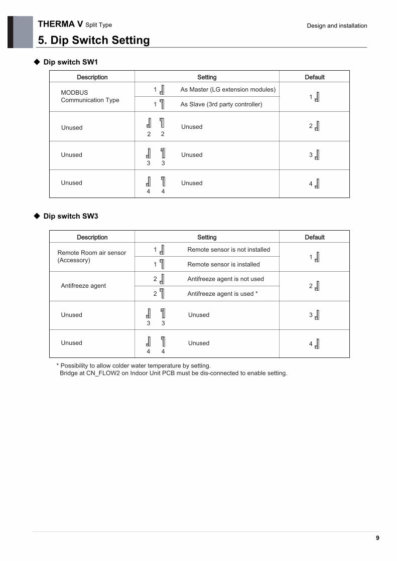
Dip switch SW1
Dip switch SW3
DescrDescriptioniption SetSettingting DefDefaultault
MODBUSCommunication Type
Unused
Unused
1
1
As Master (LG extension modules)
As Slave (3rd party controller)
2 2
3 3
44
Unused
Unused
1
2
3
4
UnusedUnused
DescrDescriptioniption SetSettingting DefDefaultault
Remote Room air sensor(Accessory)
Antifreeze agent
Unused
Unused
1
1
Remote sensor is not installed
Remote sensor is installed
2
2
Antifreeze agent is not used
Antifreeze agent is used *
33
4 4
Unused
Unused
1
2
3
4
* Possibility to allow colder water temperature by setting.Bridge at CN_FLOW2 on Indoor Unit PCB must be dis-connected to enable setting.

THERMA V Split Type
5. Dip Switch Setting
10
Design and installation
Dip switch SW2(for Hydro Box Type)DescrDescriptioniption SetSettingting DefDefaultault
Group control1
1
As Master
As Slave
Accessory installationinformation
2 3
76
32
76
2 3
76
32
6 7
Heat pump is installed(Heating(Cooling) circuit only)
Heat pump+ DHW tankis installed
Unused
Full capacity is used
Heat pump+ DHW tank+ Solar thermal systemis installed
Cycle4
4
Heating Only
Heating & Cooling
Flow SensorDetection
5 Always
5 While water pump is on
Selecting BackupHeater capacity
Electric Heater is not used
Unused
8Thermostat installationinformation
8
Thermostat is NOT installed
Thermostat is installed
1
2
3
4
5
8
6
7
Half capacity is used

5. Dip Switch Setting
11
THERMA V Split Type Design and installation
Dip switch SW2(for IWT)
DescrDescriptioniption SetSettingting DefDefaultault
Group control1
1
As Master
As Slave
Accessory installationinformation
2 3
76
32
76
2 3
76
32
6 7
Unit + Outdoor unit+ DHW tankis installed
Unused
Unused
Cycle4
4
Heating Only
Heating & Cooling
Selecting ElectricHeater operation
Electric heater is not used
Unused
8Thermostat installationinformation 8
Thermostat is NOT installed
Thermostat is installed
1
2
3
4
8
6
7Electric heater is used

THERMA V Split Type
5. Dip Switch Setting
12
Design and installation
■ Outdoor Unit
Dip switch Information
• Only DIP-switch no. 2 and no.3 has a function. Others have no function.• When setting the Partial mode, mode can be exited to secure capacity after operating for a certain time.
Description Setting Default
Low Noise Mode 2OFF Always Mode
: Maintain Low noise mode for target temperature
OFFON Partial mode: Escape Low noise mode for target temperature
Peak Control 3OFF Max Mode
ON Peak Control : To limit maximum current (Power saving)
SW1
OFF
ON
2 1
OFF is selected
5
ON is selected
3 4

Air SolutionLG Electronics Inc, 128, Yeoui-daero, Yeongdeungpo-gu, Seoul, Korea (07336)http://partner.lge.com
Copyright © 2019-2020 LG Electronics Inc. All Rights Reserved.Printed in Korea September / 2020
The air conditioners manufactured by LG have received ISO9001 certificate for quality assurance and ISO14001 certificate for environmental management system.The specifications, designs, and information in this brochure are subject to change without notice.