
Air Suspension Products Brake and for Trailers Air Suspension Products
220
Brake and Air Suspension Products for Trailers Product Catalogue Y007570: EN: 004: MAX1: Released:Webmaster: 2008/02/27-19:32:33
Transcript of Air Suspension Products Brake and for Trailers Air Suspension Products

Brake and Air Suspension Products
for Trailers
Bra
ke a
nd
Air
Su
spen
sio
n P
rod
uct
sfo
r T
rail
ers P r o d u c t C a t a l o g u e
Knorr-BremseSysteme für Nutzfahrzeuge GmbHMoosacher Straße 8080809 MunichGermanyTel: +49 89 3547-0Fax: +49 89 3547-2767
Knorr-BremseAustralia Pty. Ltd.1/2D Factory StreetPO Box 180Granville NSW 2142AustraliaTel: +61 1300 309-991Fax: +61 2 8863-6151
Knorr-Bremse GmbHSysteme für NutzfahrzeugeBeethovengasse 43-452340 MödlingAustriaTel: +43 2236 409-436Fax: +43 2236 409-434
Knorr-BremseBenelux B.V.B.A.Impulsstraat 11Industriepark zone D2220 Heist-op-den-BergBelgiumTel: +32 1525 7900Fax: +32 1524 9240
Knorr-BremseSistemas para Veículos Comerciais Brasil Ltda.Av. Engenheiro Eusébio Stevaux, 873JurubatubaSão Paulo – SPCep: 04696-902BrazilTel: +55 11 5681 1104Fax: +55 11 5686 3905
Knorr-Bremse Far East Ltd.Truck Brake Systems DivisionSuite 2901, 29/F., Central Plaza18 Harbour RoadWanchaiHong KongChinaTel: +852 2861 2669Fax: +852 2520 6259
Knorr-Bremse Brake Equipment (Shanghai) Co. Ltd.Truck Brake Systems DivisionSection A, Building 31390 Aidu RoadWaigaoqiao Free Trade ZoneShanghai, 200131ChinaTel: +86 21 5046-0776Fax: +86 21 5046-3427
Knorr-BremseSystémy pro uz̆itková vozidla, C̆R, s.r.o.Petra Bezruc̆e 399463 62 HejniceCzech RepublicTel: +420 482 363-611Fax: +420 482 363-711
Knorr-BremseSystèmes pour Véhicules Utilitaires France S.A.BP 34178RN 13, La BriqueterieGlos14104 Lisieux CedexFranceTel: +33 2 3132 1200Fax: +33 2 3132 1303
Hasse & Wrede GmbHGeorg-Knorr-Straße 412681 BerlinGermanyTel: +49 30 9392-3101Fax: +49 30 7009-0811
Knorr-BremseFékrendszerek Kft.KecskemétSzegedi út 496000HungaryTel: +36 76 511 100Fax: +36 76 481 100
Knorr-BremseSystems for Commercial Vehicles India Private Ltd.Survey No 280 & 281,Hinjawadi Phase II,Village Mann,Taluka Mulshi,Pune 411 057IndiaTel: +91 20 2293 9141-47Fax: +91 20 2293 9148
Knorr-BremseSistemi per Autoveicoli Commerciali S.p.A.Via Alessandro Polini, 15820043 ArcoreItalyTel: +39 039 6075-1Fax: +39 039 6075-435
Knorr-Bremse Commercial Vehicle Systems Japan Ltd.3-1-15, NishiikebukuroToshima-kuTokyo 171 0021JapanTel: +81 3 3971-8501Fax: +81 3 3971-8579
Knorr-Bremse Korea Ltd.Truck Brake Division6 FL, Bongwoo B/D, 31-7, 1-GaJangchung-Dong, Jung-GuSeoul 100-391KoreaTel: +82 2 2273-1182Fax: +82 2 2273-1184
Knorr-BremseBenelux B.V.B.A.Rendementsweg 4N3641 SK MydrechtNetherlandsTel: +31 297 239-330Fax: +31 297 239-339
Knorr-Bremse RUSPamirskaja Str. 11603029 Nischnij NovgorodRussian FederationTel: +7 Fax: +7
Knorr-BremseSysteme für Nutzfahrzeuge GmbHRepresentation Office Russia1. Kasatschij Pereulok 5/2119017 MoscowRussian FederationTel: +7 095 234-4995Fax: +7 095 234-4996
Knorr-Bremse S.A. Pty. Ltd.3 Derrick Road(corner Chestnut Road)1610 Kempton ParkSouth AfricaTel: +27 11 961-7800Fax: +27 11 975-8249
Bost Ibérica, S.L.Avda. Letxunborro 58Apdo. 36320303 IrunSpainTel: +34 902 100 569Fax: +34 943 614 063
Knorr-BremseSystem for Tunga Fordon ABP.O. Box 6029200 11 MalmoeSwedenTel: +46 40 680 5880Fax: +46 40 937490
Knorr-BremseSysteme für Nutzfahrzeuge GmbHOffice SwitzerlandZürichstraße 468303 BassersdorfSwitzerlandTel: +41 1 888 77-55Fax: +41 1 888 77-50
Knorr-BremseSysteme für Nutzfahrzeuge GmbHLiaison Office IstanbulMeclisi Mebusan Cad. 139/AAtlantik Han Kat: 380040 Findikli - IstanbulTurkeyTel: +90 212 293-4742Fax: +90 212 293-4743
Knorr-BremseSystems for Commercial Vehicles Ltd.Century House, Folly Brook RoadEmerald Park, Emersons GreenBristolBS16 7FEUnited KingdomTel: +44 117 9846-100Fax: +44 117 9846-101
Bendix Commercial Vehicle Systems LLC901 Cleveland StreetElyria, OH 44035USATel: +1 440 329-9100Fax: +1 440 329-9105
K001
561-
EN-0
2 08
.200
5
The f
igur
ative
mar
k ”K”
and
the t
rade
mar
ks K
NORR
, KNO
RR-B
REM
SE ar
e reg
ister
ed in
the n
ame o
f Kno
rr-Br
emse
AG.
Subj
ect t
o alte
ratio
n w
ithou
t not
ice. F
or sp
ecifi
c app
licat
ion
requ
irem
ents
and
deta
ils on
the u
se of
our p
rodu
cts w
e rec
omm
end
that
you
requ
est i
ndivi
dual
cons
ulta
tion
and
docu
men
tatio
n. Th
is do
cum
ent,
eithe
r in
part
or w
hole,
may
not
be c
opied
, rep
rodu
ced
or tr
ansm
itted
in an
y for
m w
ithou
t the
prio
r exp
licit
perm
issio
n of
Kno
rr-Br
emse
Syste
me f
ür N
utzfa
hrze
uge G
mbH
. An
y con
trave
ntio
n w
ill b
e liab
le fo
r dam
ages
and
pros
ecut
ion.
The c
onte
nts o
f thi
s doc
umen
t are
also
pro
tect
ed u
nder
EU re
gulat
ion
6/20
02 an
d eq
uiva
lent l
ocal
legisl
atio
n. A
ll rig
hts r
eser
ved.
Prin
ted
in G
erm
any.
06.
2005
Y007570: EN: 004: MAX1: Released:Webmaster: 2008/02/27-19:32:33
Cat
alog
ue N
o.: K
0015
61-E
NS
ectio
n N
o.:
K00
2450
-000
Doc
. No.
:Y
0113
33-E
N-0
00
www.knorr-bremse.com www.knorr-bremsesfn.com
KNORR-BREMSESystems for Commercial Vehicles
Subject to alteration without notice. For specific application requirementsand details on the use of our products we recommend that you request individual consultation and documentation. Reproduction, even extracts,is not permitted. Printed in Germany
Introduction
This catalogue is designed to provide an overview of the range of products for trailer air braking and suspension systems available from Knorr-Bremse. The catalogue is divided into sections relating to productgroups including brake valves, ABS, EBS, actuation, air disc brake and air suspension/lift axle control. Ineach section, we have shown a selection of popular part numbers and their technical details. Finally, weinclude a section containing data sheets for Trailer brake calculations and System design.
From time to time, we will update and re-issue these sections to those people having registered catalogueownership using the card provided.
Whilst every effort has been made to ensure the accuracy of the data in this catalogue, we reserve the rightto amend or change this information without notice. Should you find any errors or omissions or have anycomments regarding catalogue layout, please send the details to your local Knorr-Bremse representative;alternatively you could contact:[email protected]
PLEASE NOTE
This catalogue is intended for the exclusive use of trained persons within the commercial vehicle industryand must not be passed on to any third party.
This catalogue has been prepared to assist customers to make their own decision on the products neededand does not purport to be all-inclusive or to contain all information necessary for this decision. No responsibility is assumed as a result of this decision or as a result of incorrect or inappropriate partsbeing fitted to a vehicle. We cannot accept any liability nor offer any guarantee regarding data accuracy, completeness or timeliness. The information in this catalogue does not represent any guarantees or ensuredcharacteristics in terms of the German civil code. No liability can be accepted based on the information, its use, recommendations or advice provided withinthis catalogue. In no event may we be held liable for any damage or loss except in the case of wilful intent orgross negligence on our part, or if any mandatory legal provisions apply.
Brand names mentioned in this catalogue are not identified as such in all cases. We would emphasise however, that they are nevertheless subject to the provisions of trademark legislation.
Texts and graphics created by us are subject to our regulations on utilisation and exploitation and may onlybe copied or reproduced with our express permission.
Any legal disputes arising from the use of this catalogue or the information contained within shall be subjectto German law.
Failure of any individual clause of this disclaimer to comply with current legal provisions does not affect thevalidity of the remaining clauses.
This disclaimer is an English translation of a German text, which should be referred to for all legal purposes.
Y007570: EN: 004: MAX1: Released:Webmaster: 2008/02/27-19:32:33

0. Index
www.knorr-bremse.com www.knorr-bremsesfn.com
KNORR-BREMSESystems for Commercial Vehicles
Subject to alteration without notice. For specific application requirementsand details on the use of our products we recommend that you request individual consultation and documentation. Reproduction, even extracts,is not permitted. Printed in Germany
0.1
Cat
alog
ue N
o.: K
0015
61-E
NS
ectio
n N
o.:
K00
2452
-002
Doc
. No.
:Y
0113
35-E
N-0
02
Section Product Type Page-No.
0 Index 0.1 - 0.20 Index (alphabetical) 0.30 Brake System Diagrams 0.4 - 0.5
Valves1 Coupling Heads KU13.., KU41.. 1.1 - 1.22 Coupling Heads with Filter KU14.. 2.1 - 2.43 In-Line Air Filter LA2103 3.14 Relay Emergency Valves AS3... 4.1 - 4.45 Relay Emergency Valves with manual Load Sensing Valve AS70.., AS71.. 5.1 - 5.26 Load Sensing Valves, manual BR13.. 6.1 - 6.37 Load Sensing Valves, mechanical suspension BR43.. 7.1 - 7.88 Load Sensing Valves, pneumatic suspension BR55.. 8.1 - 8.119 Adapter Valves DB2139 9.1 - 9.29 Retention (Threshold) Valves DB21.. 9.3 - 9.4
10 Pressure Proportioning Valves DB21.. 10.1 - 10.211 Pressure Limiting Valves DB11.. 11.1 - 11.212 Release Valves AE4211, AE4257 12.1 - 12.413 Trailer Manoeuvring (Shunt) Valves AE4261 13.1 - 13.214 Trailer Park Valves AE4262, AE4264 14.1 - 14.215 Shut-Off Valves AE21.. 15.1 - 15.216 Combined Manoeuvring (Park / Shunt) Valves AE424. 16.1 - 16.217 Park / Shunt Valves with Integrated Emergency Function AE431. 17.1 - 17.418 Non-Return (Single Check) Valves AE51.. 18.1 - 18.219 Double Check Valves AE41.., 295358 19.1 - 19.220 Relay Valves RE11.. 20.1 - 20.221 Quick Release Valves RE21.. 21.1 - 21.222 Air Reservoirs (steel / aluminium) VB.... 22.1 - 22.3 22 Plastic Pipes KR.... 22.422 Coils – 22.422 Brake Hoses BS.... 22.523 Solenoid Valves (Normally Open) AE9120 23.1 - 23.223 Solenoid Valves ( Normally Closed) EA1152 23.3 - 23.4
ABS30 Trailer ABS KB3-TA 30.1 - 30.731 ABS Relay Modulator Valves BR92.. 31.1 - 31.432 Wheel Speed Sensors 02650501.., 04860001.. 32.1 - 32.233 ABS Connection Cable (Coil) EK3150 33.134 ABS Trailer Module A18 34.1 - 34.15
EBS40 Electronic Braking System for Trailers TEBS 40.1 - 40.34
Brake Actuators50 S-Cam Brake Chambers (Long stroke, stud mounted) BX3..., BZ3... 50.1 - 50.551 Air Disc Brake Chambers BS3... 51.1 - 51.452 S-Cam Spring Brakes (diaphragm/diaphragm) BX7... 52.1 - 52.653 S-Cam Spring Brakes (diaphragm/piston) BZ9..., BX9... 53.1 - 53.454 Air Disc Spring Brakes (diaphragm/diaphragm) BS7... 54.1 - 54.455 Air Disc Spring Brakes (diaphragm/piston) BS9... 55.1 - 55.5
Y007570: EN: 004: MAX1: Released:Webmaster: 2008/02/27-19:32:33

0. Index
www.knorr-bremse.com www.knorr-bremsesfn.com
KNORR-BREMSESystems for Commercial Vehicles
Subject to alteration without notice. For specific application requirementsand details on the use of our products we recommend that you request individual consultation and documentation. Reproduction, even extracts,is not permitted. Printed in Germany
0.2
Cat
alog
ue N
o.: K
0015
61-E
NS
ectio
n N
o.:
K00
2452
-002
Doc
. No.
:Y
0113
35-E
N-0
02
Section Product Type Page-No.
Air Disc Brake60 Air Disc Brake SN5..., SN6..., SN7..., SK7... 60.161 Brake Pad Wear Indicator Kit K000... 61.1 - 61.2
Air Suspension, Lift Axle Control70 Air Suspension Levelling Valves SV13.., SV14.. 70.1 - 70.871 Raise / Lower Valves SV31.. 71.1 - 71.4
73 Height Limiting Valves (Air Suspension) AE1103 73.1 - 73.274 Pneumatic Lift Axle Control Valves LS1..., LS2..., LS3... 74.1 - 74.1175 Lift Axle Valves, pneumatically / manually controlled AE1124 75.1 - 75.376 Lift Axle Valves, electrically controlled AE1141 76.1 - 76.277 Charging Valves DR4... 77.1 - 77.278 3/2 Control Valves AE4265, AE4266 78.1 - 78.279 Throttle Check Valves SEB00778 79.180 Manifold Block LS55.. 80.1
Data Sheets90 Data Sheet for Brake Calculation – 90.190 Data Sheet for Brake Calculation and Air Suspension – 90.2
Y007570: EN: 004: MAX1: Released:Webmaster: 2008/02/27-19:32:33

0. Index (alphabetical)
www.knorr-bremse.com www.knorr-bremsesfn.com
KNORR-BREMSESystems for Commercial Vehicles
Subject to alteration without notice. For specific application requirementsand details on the use of our products we recommend that you request individual consultation and documentation. Reproduction, even extracts,is not permitted. Printed in Germany
0.3
Cat
alog
ue N
o.: K
0015
61-E
NS
ectio
n N
o.:
K00
2452
-002
Doc
. No.
:Y
0113
35-E
N-0
02
Product Type Page-No.
3/2 Control Valves AE4265, AE4266 78.1 - 78.2ABS Connection Cable (Coil) EK3150 33.1ABS Relay Modulator Valves BR92.. 31.1 - 31.4ABS Trailer Module A18 34.1 - 34.15Adapter Valves DB2139 9.1 - 9.2Air Disc Brake SN5..., SN6..., SN7..., SK7... 60.1Air Disc Brake Chambers BS3... 51.1 - 51.4Air Disc Spring Brakes (diaphragm/diaphragm) BS7... 54.1 - 54.4Air Disc Spring Brakes (diaphragm/piston) BS9... 55.1 - 55.5Air Reservoirs (steel / aluminium) VB.... 22.1 - 22.3 Air Suspension Levelling Valves SV13.., SV14.. 70.1 - 70.8Brake Hoses BS.... 22.5Brake Pad Wear Indicator Kit K000... 61.1 - 61.2Charging Valves DR4... 77.1 - 77.2Coils – 22.4Combined Manoeuvring (Park / Shunt) Valves AE424. 16.1 - 16.2Coupling Heads KU13.., KU41.. 1.1 - 1.2Coupling Heads with Filter KU14.. 2.1 - 2.4Data Sheet for Brake Calculation – 90.1Data Sheet for Brake Calculation and Air Suspension – 90.2Double Check Valves AE41.., 295358 19.1 - 19.2Electronic Braking System for Trailers TEBS 40.1 - 40.34Height Limiting Valves (Air Suspension) AE1103 73.1 - 73.2In-Line Air Filter LA2103 3.1Lift Axle Valves, electrically controlled AE1141 76.1 - 76.2Lift Axle Valves, pneumatically / manually controlled AE1124 75.1 - 75.3Load Sensing Valves, manual BR13.. 6.1 - 6.3Load Sensing Valves, mechanical suspension BR43.. 7.1 - 7.8Load Sensing Valves, pneumatic suspension BR55.. 8.1 - 8.11Manifold Block LS55.. 80.1 Non-Return (Single Check) Valves AE51.. 18.1 - 18.2Park / Shunt Valves with Integrated Emergency Function AE431. 17.1 - 17.4Plastic Pipes KR.... 22.4Pneumatic Lift Axle Control Valves LS1..., LS2..., LS3... 74.1 - 74.11Pressure Limiting Valves DB11.. 11.1 - 11.2Pressure Proportioning Valves DB21.. 10.1 - 10.2Quick Release Valves RE21.. 21.1 - 21.2Raise / Lower Valves SV31.. 71.1 - 71.4
Relay Emergency Valves AS3... 4.1 - 4.4Relay Emergency Valves with manual Load Sensing Valve AS70.., AS71.. 5.1 - 5.2Relay Valves RE11.. 20.1 - 20.2Release Valves AE4211, AE4257 12.1 - 12.4Retention (Threshold) Valves DB21.. 9.3 - 9.4S-Cam Brake Chambers (Long stroke, stud mounted) BX3..., BZ3... 50.1 - 50.5S-Cam Spring Brakes (diaphragm/diaphragm) BX7... 52.1 - 52.6S-Cam Spring Brakes (diaphragm/piston) BZ9..., BX9... 53.1 - 53.4Shut-Off Valves AE21.. 15.1 - 15.2Solenoid Valves (Normally Closed) EA1152 23.3 - 23.4 Solenoid Valves (Normally Open) AE9120 23.1 - 23.2Throttle Check Valves SEB00778 79.1Trailer ABS KB3-TA 30.1 - 30.7Trailer Manoeuvring (Shunt) Valves AE4261 13.1 - 13.2Trailer Park Valves AE4262, AE4264 14.1 - 14.2Wheel Speed Sensors 02650501.., 04860001.. 32.1 - 32.2
Y007570: EN: 004: MAX1: Released:Webmaster: 2008/02/27-19:32:33

KNORR-BREMSE
1 Coupling Head with Filter "Supply" 2 2 Coupling Head with Filter "Control" 2 3 ABS Connector ISO 7638 30 4 Relay Emergency Valve 4 5 Park/Shunt Valve 16
11 Spring Brake 54, 55 12 Air Spring Bellow 13 Double Check Valve 19 14 Quick Release Valve 21 15 Charging Valve without feedback 77
6 Air Reservoir 22 7 Load Sensing Valve 8 8 ABS Trailer Module 34 9 Brake Chamber 51 10 Sensing Ring and Speed Sensor 32
Part List refers to section numbers in this catalogue
Systems for Commercial Vehicles Semi-trailer Brake and Air Suspension Systems with ABS
1
4
3
2
LS
300
0
KNORRBREMSE
1
3
2
241
42
KN
OR
R-B
RE
MS
E
11 12
11 12
11 12
11 12
2121
12
11
23
2
5
4
3
15 16 17
19
18
7
6
9
2021
1413
22
8
10
11
12
1
12
11
2
3
KNORR-BREMSE
4
3
2
1
1-2
1 1 122
2
1
2
2
12
11
1
4
23 23 23
22 22 22
3KNORR-DAHL
1121 221
2
3
16 In-Line Filter 3 17 3/2 Control Valve 78 18 Lift Axle Control Valve, 74 pneumatically controlled 19 Lift Bellows
20 Levelling Valve 70 21 Raise/Lower Valve 71, 72 22 Test Connector
SupplyService BrakeParking BrakeAir SuspensionElectrical Signal
VF00075/226 ENStand: 04.03.03
Cat
alog
ue N
o.: K
0015
61-E
NS
ectio
n N
o.:
K00
2453
-000
Doc
. No.
:Y
0113
36-E
N-0
00
Y00
7570
: EN
: 004
: MA
X1:
Rel
ease
d:W
ebm
aste
r: 2
008/
02/2
7-19
:32:
33

Knorr-Bremse Electronic Braking System for Trailers
SupplyService BrakeParking BrakeAir SuspensionCAN-SignalElectrical Signal
42
22
1-2
3 3
23
1.11.2
4
24
21
11 12
11 12
11 12
11 12
2121
12
11
23
2
1
8
3
7
20
1910
6 18
13
12 9
16
17
21
1 Coupling Head with Filter ÓSupplyÓ 2 Coupling Head with Filter ÓControlÓ 3 EBS Connection ISO 7638 4 Park / Shunt Valve with Emergency Function 5 Air Resevoir
6 EBS Trailer Module 7 Brake Chamber 8 Spring Brake 9 Air Disc Brake 10 Brake Disc
11 Sensing Ring and Speed Sensor 12 Wear Sensor 13 Pressure Protection Valve 14 Line Filter 15 Air Reservoir, Suspension
21 Junction Block 22 Test Connector
16 Levelling Valve 17 Raise / Lower Valve 18 Lift Axle Valve 19 Air Spring Bellows 20 Lift Bellows
11
23
21
1
3
5 14
41
3
2
1-2
22
11P-00302/EBS Anh EN
15
KNORR-BREMSESystems for Commercial Vehicles
12
2
1113
Y007570: EN: 004: MAX1: Released:Webmaster: 2008/02/27-19:32:33

1. Coupling Heads KU13.., KU41..
www.knorr-bremse.com www.knorr-bremsesfn.com
KNORR-BREMSESystems for Commercial Vehicles
Subject to alteration without notice. For specific application requirementsand details on the use of our products we recommend that you request individual consultation and documentation. Reproduction, even extracts,is not permitted. Printed in Germany
1.1
Cat
alog
ue N
o.: K
0015
61-E
NS
ectio
n N
o.:
K00
2455
-000
Doc
. No.
:Y
0113
38-E
N-0
00
Function
Coupling Heads are used to connect the braking systems of the towing vehicle and trailer.
Coupling Heads are colour coded to indicate the Control (Yellow) and Supply(Red) air line connections and are designed as defined in DIN ISO 1728 toprevent wrong connection.
Technical Features
Maximum Operating Pressure: 8,5 barOperating Temperature Range: -40 °C to +80 °CMedium: Compressed airApproximate weight: 0,2 kgYellow and Red Coupling Heads are not interchangeable.
Product overview
Type No. Application / Colour Thread G3) Dimension L3) [mm] Vehicle Application
KU1304 Control Line/YellowM22x1,5
Max. 65,5Trailer
1)
KU1305 Supply Line/Red Max. 65,5
KU1310 Supply Line/RedM16x1,5
Max. 65,5Trailer
1)
KU1311 Control Line/Yellow Max. 65,5
KU4124 Supply Line/RedM16x1,5
50Towing Vehicle
2)
KU4128 Control Line/Yellow 50
1) without Self-Sealing Valve2) with Self-Sealing Valve3) see page 1.2
Standard Symbol as DIN ISO 1219
for Trailer
for Towing Vehicle
KU 13..
1 2
KU 41..
1 2
GrF 0155
Y007570: EN: 004: MAX1: Released:Webmaster: 2008/02/27-19:32:33

1. Coupling Heads KU13.., KU41..
www.knorr-bremse.com www.knorr-bremsesfn.com
KNORR-BREMSESystems for Commercial Vehicles
Subject to alteration without notice. For specific application requirementsand details on the use of our products we recommend that you request individual consultation and documentation. Reproduction, even extracts,is not permitted. Printed in Germany
1.2
Cat
alog
ue N
o.: K
0015
61-E
NS
ectio
n N
o.:
K00
2455
-000
Doc
. No.
:Y
0113
38-E
N-0
00
Dimensions, Trailer Coupling (Without Self-Sealing Valve)
KU1305KU1310
Red
L
SW24
R44
R28
54°
45°
35
Miscoupling Safeguardfor Supply Line
1
G47
KU1304KU1311
2
L
SW24
1
G47
2
Stop
Yellow
R44
R28
54°
45°
35
Miscoupling Safeguardfor Control Line
Stop
VF 00075/53 EN
Ports:
1 = Supply2 = Delivery
Dimensions, Towing Vehicle Coupling (With Self-Sealing Valve)
38
44
20
40
22
13
KU4124
L
G
1
22143
Red
38
44
20
40
22
13
KU4128
L
G
1
22143
Yellow
VF 00075/87 EN
Across FlatsSW23
Across FlatsSW23
Ports:
1 = Supply2 = Delivery
Miscoupling Safeguardfor Supply Line
Miscoupling Safeguardfor Control Line
Y007570: EN: 004: MAX1: Released:Webmaster: 2008/02/27-19:32:33

2. Coupling Heads with Filter KU14..
www.knorr-bremse.com www.knorr-bremsesfn.com
KNORR-BREMSESystems for Commercial Vehicles
Subject to alteration without notice. For specific application requirementsand details on the use of our products we recommend that you request individual consultation and documentation. Reproduction, even extracts,is not permitted. Printed in Germany
2.1
Cat
alog
ue N
o.: K
0015
61-E
NS
ectio
n N
o.:
K00
2456
-002
Doc
. No.
:Y
0113
39-E
N-0
02
Function
Coupling Heads are used to connect the braking systems of the towing vehi-cle and trailer. An integral filter protects the air brake system and the auxiliarysystems of the trailer from contamination.To prevent a blocked filter trapping air pressure in the Supply or Control lines,a by-pass feature allows air to flow back through the valve.
Coupling Heads are colour coded to indicate the Control (Yellow) and Supply(Red) air line connections and are designed as defined in DIN ISO 1728 to prevent wrong connection.
The versions for semi-trailers are designed to prevent the rotation of the coup-ling head when connecting or disconnecting the air line.
Technical Features
Maximum Operating Pressure: 8,5 barOperating Temperature Range: -40°C to +80°CMedium: Compressed airFilter: IntegratedApproximate weight: 0,3 kgYellow and Red Coupling Heads are not interchangable.
Product overview
Type No. Part No. Application/ Pneumatic Mounting Test Typical
Colour Thread Thread Connec- Vehicle
(internal) tor Application
KU14001) K000952 Supply/Red M16x1,5 M24x1,5 -
KU14101) K000954 Control/Yellow M16x1,5 M24x1,5 - Semi-trailers
KU14121) K000956 Control/Yellow M16x1,5 M24x1,5 With
KU1401 K000953 Supply/Red M16x1,5 - - Centre Axle
KU1411 K000955 Control/Yellow M16x1,5 - With and Drawbar
KU1413 K000957 Control/Yellow M16x1,5 - - trailers
1) Locknut and shim plate supplied
Maintenance Advice
In service, the filter can be easily inspected for contamination without havingto disassemble the body of the air filter.
If the filter is heavily contaminated, the bayonet type lock on the bottom of thefilter must be pushed in and turned by 90° anti-clockwise at the same time.The filter can then be removed and washed out.
Tightening torques:M16x1,5: 45 NmM24x1,5: 60 Nm
VF 00199_161
KU1400
VF 00199_162
KU1410
Standard Symbol as DIN ISO 1219
KU1400, KU1401,KU1410, KU1413
KU1411, KU1412
KU 1400
1 2
KU 1412
1 2
Y007570: EN: 004: MAX1: Released:Webmaster: 2008/02/27-19:32:33

2. Coupling Heads with Filter KU14..
www.knorr-bremse.com www.knorr-bremsesfn.com
KNORR-BREMSESystems for Commercial Vehicles
Subject to alteration without notice. For specific application requirementsand details on the use of our products we recommend that you request individual consultation and documentation. Reproduction, even extracts,is not permitted. Printed in Germany
2.2
Cat
alog
ue N
o.: K
0015
61-E
NS
ectio
n N
o.:
K00
2456
-002
Doc
. No.
:Y
0113
39-E
N-0
02
Dimensions
Y007570: EN: 004: MAX1: Released:Webmaster: 2008/02/27-19:32:33

2. Coupling Heads with Filter KU14..
Quattro-Matic Coupling Head
www.knorr-bremse.com www.knorr-bremsesfn.com
KNORR-BREMSESystems for Commercial Vehicles
Subject to alteration without notice. For specific application requirementsand details on the use of our products we recommend that you request individual consultation and documentation. Reproduction, even extracts,is not permitted. Printed in Germany
2.3
Cat
alog
ue N
o.: K
0015
61-E
NS
ectio
n N
o.:
K00
2456
-002
Doc
. No.
:Y
0113
39-E
N-0
02
Function
The Quattro-Matic coupling is used to connect the braking systems of thetowing vehicle and trailer.
In the housing of the Quattro-Matic Coupling Head the ports for Supply andControl line as well as two in-line air filters are combined into one unit
Internal filters protect the air braking system and the auxiliary systems of thetrailer from contamination.To prevent a blocked filter trapping air pressure in the Supply or Control lines,a by-pass feature allows air to flow back through the valve. In the same way,the releasing of the brake is ensured in case of a blocked filter, which meansthat the filter opens in both directions.
The Quattro-Matic Coupling Head is available in a version for semi-trailers aswell as for drawbar and centre axle trailers. It is normally compatible with similar design coupling heads of other manufacturers.
Technical Features
Maximum Operating Pressure: max. 10 barOperating Temperature Range: -40°C to +80°CMedium: Compressed airFilter: Integrated, opens in both directionsApproximate Weight: KU1414 0,920 kg
KU1415 0,463 kg
Product overview
Maintenance Advice
In service, the filter can be easily inspected for contamination without havingto disassemble the body of the air filter.
If the filter is heavily contaminated, the bayonet type lock on the bottom of thefilter must be pushed in and turned by 90° anti-clockwise at the same time.The filter can then be removed and washed out if necessary.
Re-assembly of the filter is carried out in reverse order.
Max. Tightening torques:M16x1,5: 45 Nm
VF00199_300
KU1414
VF00199_301
KU1415
Standard Symbol as DIN ISO 1219
KU1414, KU1415
KU1414
4 24
1 21
Type No. Part No. Pneumatic Mounting Further Vehicle ApplicationThread Thread technical
(internal) details
KU1414 K002640 M16x1,5 M22x1,5 Y010964 Semi-trailersCentre Axle KU1415 K002641 M16x1,5 M22x1,5 Y011011 and Drawbar trailers
Y007570: EN: 004: MAX1: Released:Webmaster: 2008/02/27-19:32:33

2. Coupling Heads with Filter KU14..
Quattro-Matic Coupling Head
www.knorr-bremse.com www.knorr-bremsesfn.com
KNORR-BREMSESystems for Commercial Vehicles
Subject to alteration without notice. For specific application requirementsand details on the use of our products we recommend that you request individual consultation and documentation. Reproduction, even extracts,is not permitted. Printed in Germany
2.4
Cat
alog
ue N
o.: K
0015
61-E
NS
ectio
n N
o.:
K00
2456
-002
Doc
. No.
:Y
0113
39-E
N-0
02
Dimensions
KU1414
KU1415
Y007570: EN: 004: MAX1: Released:Webmaster: 2008/02/27-19:32:33

3. In-Line Air Filter LA2103
www.knorr-bremse.com www.knorr-bremsesfn.com
KNORR-BREMSESystems for Commercial Vehicles
Subject to alteration without notice. For specific application requirementsand details on the use of our products we recommend that you request individual consultation and documentation. Reproduction, even extracts,is not permitted. Printed in Germany
3.1
Cat
alog
ue N
o.: K
0015
61-E
NS
ectio
n N
o.:
K00
2457
-000
Doc
. No.
:Y
0113
40-E
N-0
00
Note: An In-Line Air Filter is already integrated in Coupling Heads KU14..
Function
The In-Line Air Filter is used in air brake systems to protect sensitive pneumatic devices from contamination.
It is typicalIy fitted in the Supply and Control lines on trailers to protect the trailer brake system from contamination that may be present in the air supplyfrom the towing vehicle, particularly as a result of coupling and uncoupling ofthe lines.
To stop a blocked filter trapping air pressure in the Supply or Control lines, theValve has a by-pass feature which allows air to flow back through the valveunfiltered.
The condition of the filter element should be checked regularly and it shouldbe cleaned if necessary.
Technical Features
Maximum Operating Pressure: 20 barOperating Temperature Range: -40 °C to +80 °CMedium: Compressed airApproximate weight: 0,2 kg
Product overview
Type No. Port Threads
LA2103 M22x1,5 - 13
KNORR-BREMSE
GrF 0349
Standard Symbol as DIN ISO 1219
1 2
LA 2103
1
2
Ports:
1 = Inlet 2 = Delivery
30°82
38
5660
Clearance required toremove filter insert
VF 00075/54 EN
≈ 88
≈ 87
≈ 50
Dimensions
Y007570: EN: 004: MAX1: Released:Webmaster: 2008/02/27-19:32:33

4. Relay Emergency Valves AS3...
www.knorr-bremse.com www.knorr-bremsesfn.com
KNORR-BREMSESystems for Commercial Vehicles
Subject to alteration without notice. For specific application requirementsand details on the use of our products we recommend that you request individual consultation and documentation. Reproduction, even extracts,is not permitted. Printed in Germany
4.1
Cat
alog
ue N
o.: K
0015
61-E
NS
ectio
n N
o.:
K00
2458
-001
Doc
. No.
:Y
0113
41-E
N-0
01
Standard Symbol as DIN ISO 1219
AS3000A AS3018
AS3100A
AS3050A
Type / Predominance Ports Manoeu-Part No. Adjustment Pre-set vring
range 2) to 1, 1-2, 4 2 Valve[bar] [bar]
AS3000A 0 - 0,5 0 M22x1,5 M22x1,5 –
AS3018 0 - 0,5 0 M22x1,5 1) –SEB00409
AS3050A without 0 M22x1,5 M22x1,5 –
AS3100A 0 - 0,5 0 M22x1,5 M22x1,5 With 3)
1) 4x M16x1,5 and 2x M22x1,52) Caution: The predominance must not be adjusted to higher
than 0,5 bar3) The Manoeuvring Valve has the Type Number AE4232
VF 00199_110
AS3000A
VF 00199_106
AS3100A
2
4
1-2
3
1
AS 3000A
2
4
1-23
1
AS 3000
2
4
1-2
3
1
AS 3050A 2
4
1-2
3
1
AS 3100A
Function
The Relay Emergency Valve transmits the brake demand of the driver tothe trailer's service brakes.
In the event of a loss of pressure in the trailer Supply (Red) line, for examplefrom an intentional or accidental uncoupling, the emergency feature of thevalve will automatically apply the trailer service brakes using the air stored inthe trailer reservoir. This function is also apparent when charging the trailerfrom zero pressure; the trailer service brakes will be partially applied until thecharge pressure exceeds approximately 3.0 bar – see "Emergency Braking"graph on page 4.2.
Most Relay Emergency Valves have a Predominance feature that generates apressure to the service (port 2) brakes higher than signal (port 4). This featureis used to compensate for threshold pressure losses through the trailer braking system and aims to ensure equal pressure at the Control (Yellow) lineand Brake Chambers.
The AS3100A version incorporates a Manoeuvring Valve that allows therelease and application of the trailer service brakes when the trailer is not cou-pled to the drawing vehicle. If the reservoir pressure is below approximately2,5 bar the service brakes cannot be released.The Manoeuvring Valve returns automatically to the driving position when theSupply (Red) line is recoupled.
The Relay Emergency Valves AS3000A, AS3050A and AS3100A have anintegrated exhaust silencer.
Technical Features
Maximum operating pressure: 10 barOperating Temperature Range: -40 °C to +80 °CMaximum torque for fittings M22x1,5: 60 NmApproximate weight: 1,6 kg
Product overview
Y007570: EN: 004: MAX1: Released:Webmaster: 2008/02/27-19:32:33

4. Relay Emergency Valves AS3...
www.knorr-bremse.com www.knorr-bremsesfn.com
KNORR-BREMSESystems for Commercial Vehicles
Subject to alteration without notice. For specific application requirementsand details on the use of our products we recommend that you request individual consultation and documentation. Reproduction, even extracts,is not permitted. Printed in Germany
4.2
Cat
alog
ue N
o.: K
0015
61-E
NS
ectio
n N
o.:
K00
2458
-001
Doc
. No.
:Y
0113
41-E
N-0
01
0 2 4 6 8
2
4
6
8
VF 00075/128 EN
1
0 2 4 6 8
2
4
6
8
3
2
1
AS3050A
0 2 4 6 8
2
4
6
8
4
1 = Predominance at 0 bar= Predominance at 0.5 bar= Predominance Setting Range= Initial charging
234
Emergency Braking
AS3000A, AS3018AS3050A, AS3100A
Service Braking
AS3000A, AS3018AS3100A
Pre
ssur
e in
bar
at P
ort 2
Pre
ssur
e in
bar
at P
ort 2
Pre
ssur
e in
bar
at P
ort 2
Pressure in bar at Port 4
Pressure in bar at Port 4
Pressure in bar at Port 1
Performance Charts
Dimensions
AS3000AAS3050A
Y007570: EN: 004: MAX1: Released:Webmaster: 2008/02/27-19:32:33

4. Relay Emergency Valves AS3...
www.knorr-bremse.com www.knorr-bremsesfn.com
KNORR-BREMSESystems for Commercial Vehicles
Subject to alteration without notice. For specific application requirementsand details on the use of our products we recommend that you request individual consultation and documentation. Reproduction, even extracts,is not permitted. Printed in Germany
4.3
Cat
alog
ue N
o.: K
0015
61-E
NS
ectio
n N
o.:
K00
2458
-001
Doc
. No.
:Y
0113
41-E
N-0
01
Dimensions
30
M22
x 1
,5
4971
123
12
1-2
52 52
46
510
M22
x 1
,5
34
59
56,5 64
4
71
11
22
4B
73 72 14
58 58
44
14
30
M22
x 1
,5
M16 x 1,5
A
22
14
26
78M
22 x
1,5
X
"X"
M 8
11
3
A = Warning! Compressed spring force approx. 750N
B = Undrilled
Ports: 1 = Supply (Red trailer coupling)1-2 = Trailer Reservoir 2 = Delivery to Brake Actuators 3 = Exhaust 4 = Control (Yellow trailer coupling)
VF 00075/23 ÄI01 EN
14
1
14
2 2
AS3018
AS3100A
Y007570: EN: 004: MAX1: Released:Webmaster: 2008/02/27-19:32:33

4. Relay Emergency Valves AS3...
www.knorr-bremse.com www.knorr-bremsesfn.com
KNORR-BREMSESystems for Commercial Vehicles
Subject to alteration without notice. For specific application requirementsand details on the use of our products we recommend that you request individual consultation and documentation. Reproduction, even extracts,is not permitted. Printed in Germany
4.4
Cat
alog
ue N
o.: K
0015
61-E
NS
ectio
n N
o.:
K00
2458
-001
Doc
. No.
:Y
0113
41-E
N-0
01
Testing and Setting
Testing of the Predominance feature
• Connect air pressure gauges to Ports 2 and 4 of the valve. • Predominance is present if the pressure at Port 2 is greater than the pressure
• With a constant air pressure (>6 bar) at Port 1 and a constant at port 4.2.0 bar pressure at Port 4, measure the pressure at port 2.
• Predominance levels are specified with 2.0 bar at port 4.
Adjustment of the Predominance feature:
• No pressure at port 4 • Apply 2.0 bar pressure to port 4 and• Insert a key (to DIN 3116) or small pincer (see graphic) into the measure the pressure at port 2, repeat
plastic disc (1) to adjust the predominance. procedure if required, remembering to• Turn the disc clockwise to increase the predominance or anticlockwise remove the pressure from port 4 before
to reduce the predominance - see WARNING below. each adjustment.
WARNING:
The predominance is only allowed to be set within the legal bands.
Additionally it should only be set in accordance with the vehicle manufacturer’s instructions.
The predominance must not exceed 0,5 bar.
Y007570: EN: 004: MAX1: Released:Webmaster: 2008/02/27-19:32:33

5. Relay Emergency Valves with manual Load Sensing Valve AS70..
www.knorr-bremse.com www.knorr-bremsesfn.com
KNORR-BREMSESystems for Commercial Vehicles
Subject to alteration without notice. For specific application requirementsand details on the use of our products we recommend that you request individual consultation and documentation. Reproduction, even extracts,is not permitted. Printed in Germany
5.1
Cat
alog
ue N
o.: K
0015
61-E
NS
ectio
n N
o.:
K00
2459
-000
Doc
. No.
:Y
0113
42-E
N-0
00
Function, Technical Features, Performance Charts and Dimensions
for AS3000A: see "Relay Emergency Valve AS3..." (page 4.1)for BR1305: see "Load Sensing Valve BR13.." (page 6.1).
Type No. for the combination is AS7000A.
When the trailer is not coupled, its brakes can be released by moving theLoad Sensing Valve lever to the 'Brake Released position'.
For details of the version with Manoeuvring Valve see AS71.. (page 5.2).
VF00199_171
Standard Symbol as DIN ISO 1219
AS3000A see:"Relay Emergency Valve AS3..."(page 4.1)
and BR1305 see:"Load Sensing Valve BR13.."(page 6.1)
CombinationRelay Emergency Valve AS3000Awith Load Sensing Valve BR1305
Y007570: EN: 004: MAX1: Released:Webmaster: 2008/02/27-19:32:33

5. Relay Emergency Valves with manual Load Sensing Valve AS71..
www.knorr-bremse.com www.knorr-bremsesfn.com
KNORR-BREMSESystems for Commercial Vehicles
Subject to alteration without notice. For specific application requirementsand details on the use of our products we recommend that you request individual consultation and documentation. Reproduction, even extracts,is not permitted. Printed in Germany
5.2
Cat
alog
ue N
o.: K
0015
61-E
NS
ectio
n N
o.:
K00
2459
-000
Doc
. No.
:Y
0113
42-E
N-0
00
Function, Technical Features, Performance Charts and Dimensions
For AS3100A: see "Relay Emergency Valve AS3..." (page 4.1) For BR1306: see "Load Sensing Valve BR13.." (page 6.1).
Type No. for the combination is AS7100A.
When the trailer is not coupled, its brakes can be released by pressing in theblack button on valve AS3100A.
When the Supply (Red) Line is re-connected, the black button will automati-cally 'pop out' returning it to the drive position.
VF00199_172
Standard Symbol as DIN ISO 1219
AS3100A see:"Relay Emergency Valve AS3..."(page 4.1)
and BR1306 see:"Load Sensing Valve BR13.."(page 6.1)
CombinationRelay Emergency Valve AS3100Awith Load Sensing Valve BR1306
Y007570: EN: 004: MAX1: Released:Webmaster: 2008/02/27-19:32:33

6. Load Sensing Valves, manual BR13..
www.knorr-bremse.com www.knorr-bremsesfn.com
KNORR-BREMSESystems for Commercial Vehicles
Subject to alteration without notice. For specific application requirementsand details on the use of our products we recommend that you request individual consultation and documentation. Reproduction, even extracts,is not permitted. Printed in Germany
6.1
Cat
alog
ue N
o.: K
0015
61-E
NS
ectio
n N
o.:
K00
2460
-000
Doc
. No.
:Y
0113
43-E
N-0
00
Function
The manually operated Load Sensing Valve, in connection with a RelayEmergency Valve, is used to adjust the applied service brake pressure in rela-tion to the load imposed on the trailer's axles.
Technical Features
Maximum Operating Pressure: 8,5 barOperating Temperature Range: -40 °C to +80 °CMedium: Compressed airApproximate weight: 0,6 kg
Options
GrF 0304
Standard Symbol as DIN ISO 1219
213
BR 1305
1) 1:1 Regulation up to tank pressure
Brakes Possible range of pressure adjustment at port 2 [bar]Type No. Released in lever position
position Unladen Half laden Fully laden
BR1305 With 1,8-2,5 3,0-4,5 1)
BR1306 Without 1,8-2,5 3,0-4,5 1)
Y007570: EN: 004: MAX1: Released:Webmaster: 2008/02/27-19:32:33

6. Load Sensing Valves, manual BR13..
www.knorr-bremse.com www.knorr-bremsesfn.com
KNORR-BREMSESystems for Commercial Vehicles
Subject to alteration without notice. For specific application requirementsand details on the use of our products we recommend that you request individual consultation and documentation. Reproduction, even extracts,is not permitted. Printed in Germany
6.2
Cat
alog
ue N
o.: K
0015
61-E
NS
ectio
n N
o.:
K00
2460
-000
Doc
. No.
:Y
0113
43-E
N-0
00
Dimensions
KNORR BREMSE
1/1
1/2
ø49
60
58
14
28
10
92 50
ø9
3437
,5
128
ø33
ø29,
5
60
1,7
1
0
Ports:1 = Supply2 = Delivery3 = Exhaust (not shown)
VF 00075/90 EN
Lever positions:
= Brakes Released (only BR1305)= Unladen= Half laden= Fully laden
12
BR1305BR1306
Y007570: EN: 004: MAX1: Released:Webmaster: 2008/02/27-19:32:33
6. Load Sensing Valves, manual BR13..
www.knorr-bremse.com www.knorr-bremsesfn.com
KNORR-BREMSESystems for Commercial Vehicles
Subject to alteration without notice. For specific application requirementsand details on the use of our products we recommend that you request individual consultation and documentation. Reproduction, even extracts,is not permitted. Printed in Germany
6.3
Cat
alog
ue N
o.: K
0015
61-E
NS
ectio
n N
o.:
K00
2460
-000
Doc
. No.
:Y
0113
43-E
N-0
00
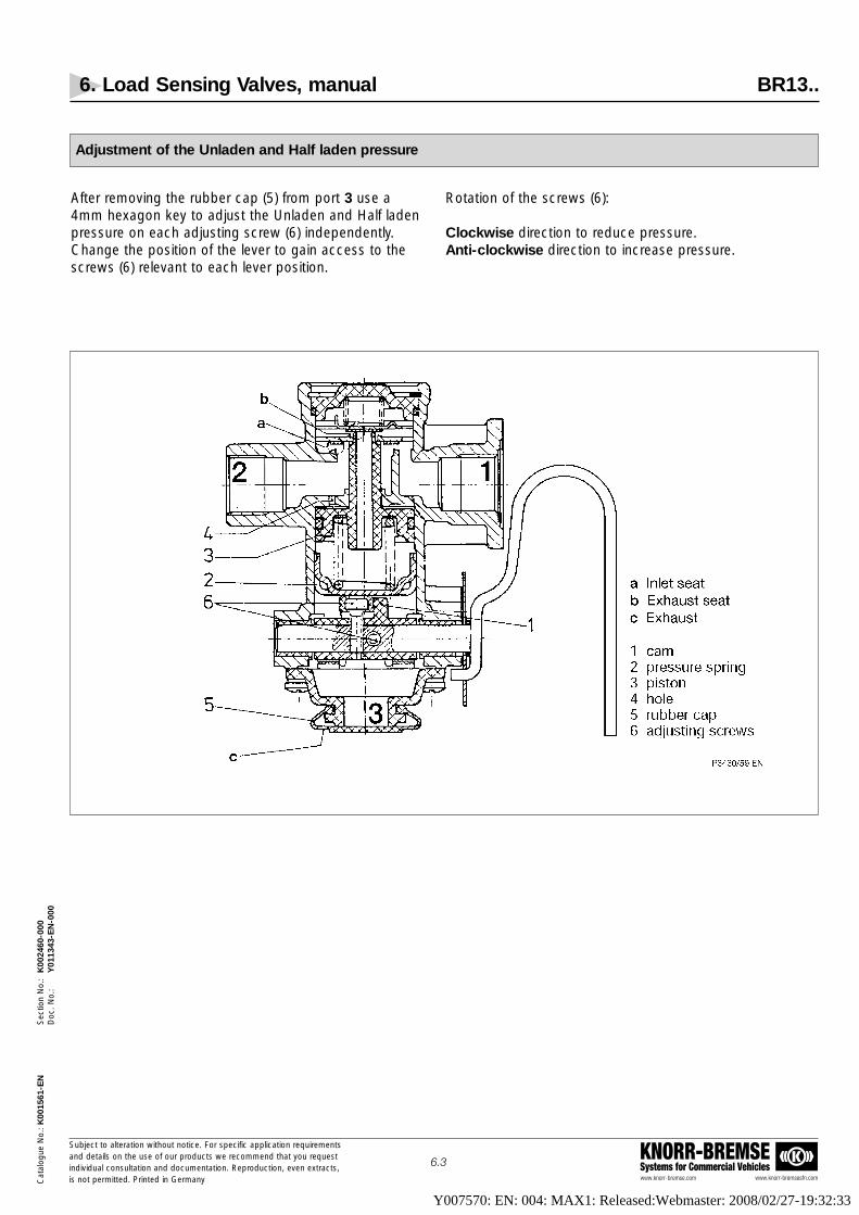
Adjustment of the Unladen and Half laden pressure
After removing the rubber cap (5) from port 3 use a4mm hexagon key to adjust the Unladen and Half ladenpressure on each adjusting screw (6) independently.Change the position of the lever to gain access to thescrews (6) relevant to each lever position.
Rotation of the screws (6):
Clockwise direction to reduce pressure.Anti-clockwise direction to increase pressure.
Y007570: EN: 004: MAX1: Released:Webmaster: 2008/02/27-19:32:33

Type No. Operation Relay RelayType Emergency feature
Valve
BR4352 dynamic With With
BR4370 static Without Without
7. Load Sensing Valves, mechanical suspension BR43..
www.knorr-bremse.com www.knorr-bremsesfn.com
KNORR-BREMSESystems for Commercial Vehicles
Subject to alteration without notice. For specific application requirementsand details on the use of our products we recommend that you request individual consultation and documentation. Reproduction, even extracts,is not permitted. Printed in Germany
7.1
Cat
alog
ue N
o.: K
0015
61-E
NS
ectio
n N
o.:
K00
2461
-001
Doc
. No.
:Y
0113
44-E
N-0
01
Function
The Load Sensing Valve is used to adjust the applied service brake pressure inrelation to the load imposed on the vehicle's axles. The mechanical suspension Load Sensing Valve uses the movement between the vehicle'schassis and axle to "sense" the load imposed on the axles.
The Valve is installed on the chassis and a Linkage is required to connect thecontrol arm of the Valve to the axles. Any movement of the chassis changesthe position of the Valve's control arm which, in turn, alters the ratio of inputpressure to output pressure.
Versions of the Valve are available with standard relay or relay emergency feature and with static or dynamic operation. A static valve uses the brakingratio at commencement of braking throughout the brake application. A dynamic valve adjusts the braking ratio throughout the brake application tocounteract the effect of axle load change due to load transfer.
To adjust the rate of change of control ratio due to change in axle load, theeffective length of the lever can be adjusted.
A trailer Data Plate showing the setting of the Load Sensing Valve is requiredby law.
Technical Features
Maximum Operating Pressure: 8,5 barOperating Temperature Range: -40 °C to +80 °CMedium: Compressed airWorking Angle : 20°Approximate weight: 2,3 kg
Options
KNORR-BREMSE
GrF 0372
Standard Symbol as DIN ISO 1219
BR4352
BR4370
4
22
31 1-2
BR 4352
213
BR 4370
Type No. A i r P o r t T h r e a d s Remark1 1-2 2 3 4
M16x1,5 (4x)BR4352 M16x1,5 M22x1,5 M16x1,5
M22x1,5 (2x)M22x1,5 With cable pull
BR4370 M22x1,5 – M16x1,5 (4x) –
Maximum adjustable lever length: 300 mm.Part number for lever with cable pull: SEB01263
Y007570: EN: 004: MAX1: Released:Webmaster: 2008/02/27-19:32:33

7. Load Sensing Valves, mechanical suspension BR43..
www.knorr-bremse.com www.knorr-bremsesfn.com
KNORR-BREMSESystems for Commercial Vehicles
Subject to alteration without notice. For specific application requirementsand details on the use of our products we recommend that you request individual consultation and documentation. Reproduction, even extracts,is not permitted. Printed in Germany
7.2
Cat
alog
ue N
o.: K
0015
61-E
NS
ectio
n N
o.:
K00
2461
-001
Doc
. No.
:Y
0113
44-E
N-0
01
Functional diagram
0 2 4 6 8
2
4
6
8
1 3 5 7
1
3
5
7
4
3
Control ratio
α=0°
α=20°
0,3 max.
0,4 +0,1-
VF 0075/25 EN
1/1
1/8
-50 -30 -10 10 30
2
4
6
8
-40 -20 0 20
1
3
5
7
50 70 9040 60 80
6
5
Delivery Pressure vs Angle
p4 = 7,5 bar
VF 00075/26 EN
0 2 4 6 8
2
4
6
8
1 3 5 7
1
3
5
7
2
1
A
Automatic braking (only BR4352)
VF 00075/27 EN
1 = Pressure in the Supply Line [bar]
= Pressure in the Brake Actuators [bar]
= Signal pressure p4 [bar]
= Delivery pressure p2 [bar]
= Lever deflection α [°]
= Delivery pressure p2 [bar]
= Initial charging
23456A
VF 00075/28 EN
Y007570: EN: 004: MAX1: Released:Webmaster: 2008/02/27-19:32:33

7. Load Sensing Valves, mechanical suspension BR43..
www.knorr-bremse.com www.knorr-bremsesfn.com
KNORR-BREMSESystems for Commercial Vehicles
Subject to alteration without notice. For specific application requirementsand details on the use of our products we recommend that you request individual consultation and documentation. Reproduction, even extracts,is not permitted. Printed in Germany
7.3
Cat
alog
ue N
o.: K
0015
61-E
NS
ectio
n N
o.:
K00
2461
-001
Doc
. No.
:Y
0113
44-E
N-0
01
Dimensions
42
84
68,1102
171)
2828
64
Ø8
24
8442
20
151)
171)
SW 22
Tightening torque 20 ±5 Nm
VF 00075/29 EN
M16x1,5
STOP
M22x1,5
M16x1,5
Working angle
M2
M1
Limitation STOP
Overtravel
M16x1,5
94
50
152 12
4
M16
x1,5
18
4
M16x1,5
M22x1,5
80° + 3°-
60°
+ 3°
- 10°
+ 1°
-
20° +
2°-
8464
,5
α-α+ α=0°
58583939
M8
58
129
168
M22x1,5
maximum threaddepth 11mm
110
Ports:
1 = Supply (from Red Trailer Coupling)
1-2 = Trailer reservoir
2 = Delivery (to Brake Actuator)
3 = Exhaust
4 = Signal (from Yellow Trailer Coupling)
M1 = Torque required to move the lever = 2 NmM2 = Max torque required to move the lever = 20 Nm
1
1-2
22
3
2
1) maximum Mounting Plate Dimension
BR4352
Y007570: EN: 004: MAX1: Released:Webmaster: 2008/02/27-19:32:33

7. Load Sensing Valves, mechanical suspension BR43..
www.knorr-bremse.com www.knorr-bremsesfn.com
KNORR-BREMSESystems for Commercial Vehicles
Subject to alteration without notice. For specific application requirementsand details on the use of our products we recommend that you request individual consultation and documentation. Reproduction, even extracts,is not permitted. Printed in Germany
7.4
Cat
alog
ue N
o.: K
0015
61-E
NS
ectio
n N
o.:
K00
2461
-001
Doc
. No.
:Y
0113
44-E
N-0
01
Dimensions
STOP
OvertravelM22x1,5
R20
M16x1,580°
58
110
107,
542
84
648
24
17 1)
Tightening torque 20 ±5 NmVF 00075/30 EN
84
42
24
53
M8
Working angle
20°
10°
50°
5570
M22x1,5
STOP
145,
5
70,5
3035
17 1
2
2
Ports:
1 = Signal from Yellow Trailer Coupling
2 = Delivery to Brake Actuators3 = Exhaust
3
1) maximum Mounting Plate Dimension
17 1)
17 1)
M2
M1
α-α+ α=0°
BR4370
maximum threaddepth 11mm
M1 = Torque required to move the lever = 2 NmM2 = Max torque required to move the lever = 20 Nm
Load Sensing Valve Data Plate (DIN 74267-C) mechanical suspension, BR43.. – Part No.: 3EB01629
Sl
Feder-NrSpring NoRessort No
bar
Automatisch-Lastabhängige Bremskraftregeleinrichtung (ALB)für Typ:Load Sensing Device for Type:Dispositif de correction automatique de frainage pour type:
Ventile NrValves NoValves No
AusgangsdruckOutput PressurePression de sortie bar
Weg s am HebelStroke s at LeverCourse s ou Levier mm
KNORR- BREMSE AG
mml=Sl mml=
AchslastAxle LoadCharge essieu kg
AusgangsdruckOutput PressurePression de sortie bar
Weg s am HebelStroke s at LeverCourse s ou Levier mm
AchslastAxle LoadCharge essieu kg
EingangsdruckInput PressurePression de entrée
Vorderachse, Front Axle, Essieu avant
Feder-NrSpring NoRessort No
Ventile NrValves NoValves No
Hinterachse, Rear Axle, Essieu arrière
VF 00075/31
Y007570: EN: 004: MAX1: Released:Webmaster: 2008/02/27-19:32:33

7. Load Sensing Valves, mechanical suspension BR43..
www.knorr-bremse.com www.knorr-bremsesfn.com
KNORR-BREMSESystems for Commercial Vehicles
Subject to alteration without notice. For specific application requirementsand details on the use of our products we recommend that you request individual consultation and documentation. Reproduction, even extracts,is not permitted. Printed in Germany
7.5
Cat
alog
ue N
o.: K
0015
61-E
NS
ectio
n N
o.:
K00
2461
-001
Doc
. No.
:Y
0113
44-E
N-0
01
Determining the Lever Length "l" (graphical)
300
275
250
225
200
175
150
125
100
75
50
25
10
1,5 1,75 2 2,5 3,53 4 5 6 8
20 30 40 50 60 70 80
Axle Spring Deflection "s" [mm]
Leve
r Le
ngth
"l"
[mm
]
Lever Length Diagram for mechanical suspension Load Sensing Valves:
BR4352, BR4370
Example:for an Axle Spring Deflection of 30 mm and a Valve Ratio of 3:1 the required Lever Length is 113 mm
VF 00075/34 EN
113
1) i =
p1 - 0,4 p2 unladen - 0,4
Valve Ratio-determined from Brake calculation i1)
Y007570: EN: 004: MAX1: Released:Webmaster: 2008/02/27-19:32:33

7. Load Sensing Valves, mechanical suspension BR43..
www.knorr-bremse.com www.knorr-bremsesfn.com
KNORR-BREMSESystems for Commercial Vehicles
Subject to alteration without notice. For specific application requirementsand details on the use of our products we recommend that you request individual consultation and documentation. Reproduction, even extracts,is not permitted. Printed in Germany
7.6
Cat
alog
ue N
o.: K
0015
61-E
NS
ectio
n N
o.:
K00
2461
-001
Doc
. No.
:Y
0113
44-E
N-0
01
Determining the Lever Length "l" (arithmetical)
Axle Spring Deflection: s [mm] =
Control (Yellow) Line pressure - input: p1 [bar] =
Load dependent brake actuator pressure - unladen: p2 unladen [bar] =
Load dependent brake actuator pressure - laden: p2 laden [bar] =
p2 unladen - 0,4Valve Ratio (unladen): iL = =
p1 - 0,4
p2 laden - 0,4Valve Ratio (laden): iV = =
p1 - 0,4
Axle Spring DeflectionLever Length "l" [mm]: l = =
Secondary variable C
Secondary variable A [angle degree]: A = 22,8 x iL - 12,8 =
Secondary variable B [angle degree]: B = 22,8 x iV - 12,8 =
Secondary variable C: C = sin (A) - sin (B) =
A computer calculation program is available on request.
Y007570: EN: 004: MAX1: Released:Webmaster: 2008/02/27-19:32:33

7. Load Sensing Valves, mechanical suspension BR43..
www.knorr-bremse.com www.knorr-bremsesfn.com
KNORR-BREMSESystems for Commercial Vehicles
Subject to alteration without notice. For specific application requirementsand details on the use of our products we recommend that you request individual consultation and documentation. Reproduction, even extracts,is not permitted. Printed in Germany
7.7
Cat
alog
ue N
o.: K
0015
61-E
NS
ectio
n N
o.:
K00
2461
-001
Doc
. No.
:Y
0113
44-E
N-0
01
How to adjust a mechanical suspension Load Sensing Valve BR43..
• Determine the lever length with the help of the brake calculation, the nomogram and the formula.
• Fit the Cable attachment on the lever at this length.
• Write the following data on the Load Sensing Valve Data Plate: input pressure; output pressure of the Load Sensing Valve, unladen and laden, axle load, unladen and laden; lever length and spring deflection.
• With the lever of the Load Sensing Valve horizontal, the connecting cable should be at right angles to it.The length of the connecting cable can be adjusted usingthe clamp screw.
• Ensure that the vehicle is on level ground and chock the wheels.
• Axle weight must be according to the data of the axle manufacturer for an unladen vehicle.
• Check that sufficient service pressure is available.
• Connect pressure gauges to the Control Line inputof the Load Sensing Valve and to the output (Brake Actuators).
Attention:
To adjust valve BR4370 with static characteristic the supply pressure must be released to make any adjustment and then the output pressure re-checked.
• Apply input (Control Line) pressure as stated on the Data Plate.
• Read the output pressure on the gauge and correct if necessary (shorten the cable to give lower unladenbrake pressure and vice versa).
• See Attention note below.
• Disconnect the cable and with reference to a suitable measuring device, raise the lever a distance "s", i.e. the distance of spring deflection as taken from the data plate.
• Apply input (Control Line) pressure as stated on the Data Plate.
• Read the output pressure and check it is the same as the Laden pressure as defined on the data plate. If it is not then correct by adjusting the lever length (shorten to increase output pressure and vice versa).Check and adjust until both unladen (with cablefitted) and laden settings are correct.See Attention note below.
After finishing the test ensure that the lever and cableclamps are tightened securely.
Y007570: EN: 004: MAX1: Released:Webmaster: 2008/02/27-19:32:33

7. Load Sensing Valves, mechanical suspension BR43..
www.knorr-bremse.com www.knorr-bremsesfn.com
KNORR-BREMSESystems for Commercial Vehicles
Subject to alteration without notice. For specific application requirementsand details on the use of our products we recommend that you request individual consultation and documentation. Reproduction, even extracts,is not permitted. Printed in Germany
7.8
Cat
alog
ue N
o.: K
0015
61-E
NS
ectio
n N
o.:
K00
2461
-001
Doc
. No.
:Y
0113
44-E
N-0
01
Rubber mounting for brake equalisation PET 76.982-00
Function
Rubber mounts are used in mechanically suspended tandem bogies to get an elastic connection between the axles.The arrrangement as shown below, 'averages' the movements of both axles. Fix the Load Sensing Valve linkage to themiddle of the cross linkage.
Installation recommendation (See note)
Fix a rubber mount (A) to each axle. If necessary, connect two rubber mount’s together with joiner (B).Inter-connect axles with tube or an angle section cross linkage (C).The fixing point for the Load Sensing Valve must be in the middle of cross linkage (C). Thread M10.
Note: Items "A”, "B”, and "C” are not supplied by Knorr-Bremse and must be manufactured by the installer to the necessary dimensions.
Y007570: EN: 004: MAX1: Released:Webmaster: 2008/02/27-19:32:33

Function
The Load Sensing Valve is used to modify the applied service brake pressurein relation to the load imposed on the vehicle’s axles. The pneumatic suspension Load Sensing Valve uses the pressure in the Suspension Air Bagsto ‘sense’ the load imposed on the axles and determine the Valve’s brakingratio.
Versions of the Valve are available with and without relay and emergency features and with static or dynamic operation. A static valve uses the brakingratio at commencement of braking application. A dynamic valve adjusts thebraking ratio throughout the brake application to help counteract the effect ofload transfer.
A Trailer Data Plate, showing the settings of the Load Sensing Valve, is required by law (See page 8.4).
Technical Features
Maximum Operating Pressure: 8,5 barOperating Temperature Range: -40 °C to +80 °CMedium: Compressed AirApprox. Weight: 2,4 kg to 3,1 kg
Options
8. Load Sensing Valves, pneumatic suspension BR55..
www.knorr-bremse.com www.knorr-bremsesfn.com
KNORR-BREMSESystems for Commercial Vehicles
Subject to alteration without notice. For specific application requirementsand details on the use of our products we recommend that you request individual consultation and documentation. Reproduction, even extracts,is not permitted. Printed in Germany
8.1
Cat
alog
ue N
o.: K
0015
61-E
NS
ectio
n N
o.:
K00
2462
-001
Doc
. No.
:Y
0113
45-E
N-0
01
Type No. Part No. Operation Relay Relay Test valveEmergency feature connection
Valve "43"
BR5504 SEB00651 Static/Dynamic With With With
BR5522 SEB01326 Static Without Without With
BR5522 II36836 Static Without Without With
BR5523 SEB01344 Dynamic Without Without With
BR5524 SEB01241 Dynamic With With Without
BR5524 SEB01509 Dynamic With With Without
BR5524 SEB01510 Dynamic With With Without
GrF 0358
Standard Symbol as DIN ISO 1219
BR5504
BR5522 BR5523
BR5524
4
31
BR 5504
22
424143
1-2
2
2
1
3
4143BR 5522
42
2
2
1
3
4143BR 5523
42
Y007570: EN: 004: MAX1: Released:Webmaster: 2008/02/27-19:32:33

8. Load Sensing Valves, pneumatic suspension BR55..
www.knorr-bremse.com www.knorr-bremsesfn.com
KNORR-BREMSESystems for Commercial Vehicles
Subject to alteration without notice. For specific application requirementsand details on the use of our products we recommend that you request individual consultation and documentation. Reproduction, even extracts,is not permitted. Printed in Germany
8.2
Cat
alog
ue N
o.: K
0015
61-E
NS
ectio
n N
o.:
K00
2462
-001
Doc
. No.
:Y
0113
45-E
N-0
01
Options - continued -
Type No. Part No. Test Point con- Air Suspension basic settingnection "p2" connection unladen laden
BR5504 SEB00651 With p41 / p42 p1/p1-2=8bar; p4=6,5bar
p41/p42=0,8bar p41/p42=5,1barp2=2bar p2=6,5bar
BR5522 SEB01326 Without p41 / p42 p1=6,5bar
p41/p42=0,5bar p41/p42=3,2barp2=2,3bar p2=6,5bar
BR5522 II36836 Without p41 / p42 p1=6,5bar
p41/p42=0,7bar p41/p42=4,6barp2=2,4bar p2=6,5bar
BR5523 SEB01344 Without p41 / p42 p1=6,5bar
p41/p42=0,5bar p41/p42=3,2barp2=2,3bar p2=6,5bar
BR5524 SEB01241 Without p42 p1/p1-2=8bar; p4=6,5bar
p42=0,5bar p42=4,4barp2=2bar p2=5,2bar
BR5524 SEB01509 Without p42 p1/p1-2=8bar; p4=6,5bar
p42=0,7bar p42=2,4barp2=3,8bar p2=6,5bar
BR5524 SEB01510 Without p42 p1/p1-2=8bar; p4=6,5bar
p42=0,5bar p42=3,6barp2=2bar p2=6,5bar
Type No. Part No. A i r P o r t T h r e a d s1 1-2 2 4 41 / 42
or 42
BR5504 SEB00651 M16x1,5 M22x1,5 M16x1,5 (4x) M16x1,5 M12x1,5– M22x1,5 (2x)
BR5522 SEB01326 M22x1,5 – M16x1,5 (2x) – M12x1,5
BR5522 II36836 M22x1,5 – M16x1,5 (2x) – M12x1,5
BR5523 SEB01344 M22x1,5 – M16x1,5 (2x) – M12x1,5
BR5524 SEB01241 M16x1,5 M22x1,5 M22x1,5 (2x) M16x1,5 M12x1,5
BR5524 SEB01509 M16x1,5 M22x1,5 M22x1,5 (2x) M16x1,5 M12x1,5
BR5524 SEB01510 M16x1,5 M22x1,5 M22x1,5 (2x) M16x1,5 M12x1,5
GrF 0358
Standard Symbol as DIN ISO 1219
BR5504
BR5522 BR5523
BR5524
4
31
BR 5504
22
424143
1-2
2
2
1
3
4143BR 5522
42
2
2
1
3
4143BR 5523
42
Y007570: EN: 004: MAX1: Released:Webmaster: 2008/02/27-19:32:33

8. Load Sensing Valves, pneumatic suspension BR55..
www.knorr-bremse.com www.knorr-bremsesfn.com
KNORR-BREMSESystems for Commercial Vehicles
Subject to alteration without notice. For specific application requirementsand details on the use of our products we recommend that you request individual consultation and documentation. Reproduction, even extracts,is not permitted. Printed in Germany
8.3
Cat
alog
ue N
o.: K
0015
61-E
NS
ectio
n N
o.:
K00
2462
-001
Doc
. No.
:Y
0113
45-E
N-0
01
0 2 4 6 8
2
4
6
8
0.3 Max.
4
3
0.4+0.1-1/8
1/1
VF00075/5 EN
Control Ratio
7531
1
3
5
7
0 2 4 6 8
2
4
6
8
1 3 5 7
1
3
5
7
Emergency Braking
0 2 4 6 8
2
4
6
8
1 3 5 7
1
3
5
7
A
2
1VF00075/7 EN
1
Legend:
= Pressure in the Supply Line [bar]
= Pressure in the Brake Actuators [bar]
= Signal Pressure p [bar]
= Delivery Pressure p2 [bar]
= Control Pressure p41 p42 [bar]
= Delivery Pressure p2 [bar]
= Initial Charging
23456A
VF00075/8 EN
Performance charts
1)
1) only for BR5504 and BR5524
Y007570: EN: 004: MAX1: Released:Webmaster: 2008/02/27-19:32:33

8. Load Sensing Valves, pneumatic suspension BR55..
www.knorr-bremse.com www.knorr-bremsesfn.com
KNORR-BREMSESystems for Commercial Vehicles
Subject to alteration without notice. For specific application requirementsand details on the use of our products we recommend that you request individual consultation and documentation. Reproduction, even extracts,is not permitted. Printed in Germany
8.4
Cat
alog
ue N
o.: K
0015
61-E
NS
ectio
n N
o.:
K00
2462
-001
Doc
. No.
:Y
0113
45-E
N-0
01
VF00075/9
Load Sensing Valve Data Plate (DIN 74267-C) for pneumatic Load Sensing Valve BR55.. – Part No.: 3EB01630
The fitting of the Load Sensing Valve Data Plate is essential to ensure that the optimum performance from the Load Sensing Valve can be maintained once the trailer is in service.
The plate should be stamped with the following data:
Valves No. = Part No. of the Load Sensing Valve fitted to the trailerAxle Load = Unladen & laden axle weights (used for setting the valve ratio)
Input pressure = The inlet pressure at the Load Sensing Valve (used for setting unladen & laden valve ratios)Output pressure = The outlet pressures required when the Load Sensing Valve is set correctly (unladen & laden)
Suspension pressure = The air suspension bag pressures for the stated axle weights (unladen & laden)
Y007570: EN: 004: MAX1: Released:Webmaster: 2008/02/27-19:32:33

8. Load Sensing Valves, pneumatic suspension BR55..
www.knorr-bremse.com www.knorr-bremsesfn.com
KNORR-BREMSESystems for Commercial Vehicles
Subject to alteration without notice. For specific application requirementsand details on the use of our products we recommend that you request individual consultation and documentation. Reproduction, even extracts,is not permitted. Printed in Germany
8.5
Cat
alog
ue N
o.: K
0015
61-E
NS
ectio
n N
o.:
K00
2462
-001
Doc
. No.
:Y
0113
45-E
N-0
01
��
S
D
S = "Static" setting
D = "Dynamic" setting
s
s
367
21
M16x1,5
M16x1,5
M22x1,5
M16x1,5
M12x1,5
168
39
226
170
131
66 1515
84
64
39
17
28
M8
SW 2,5
test connection for p2
test valve connection for p41, p42
SW 19 SW 10
28
42 4215
11658
51
17
207 94
53110
116
ø44
ø38
1
42412
2 23
1-2
M8
8417
2726
17
R8
152
58
20
43,5
18,5
12410
2
VF00075/10 EN
43
BR5504
Ports:
1 = Supply (from red trailer coupling)1-2 = Trailer reservoir
2 = Delivery to brake actuators 3 = Exhaust 4 = Signal (from yellow trailer coupling)
41 = Signal (from air suspension)42 = Signal (from air suspension)43 = Test fitting
Dimensions
BR5504
Y007570: EN: 004: MAX1: Released:Webmaster: 2008/02/27-19:32:33

8. Load Sensing Valves, pneumatic suspension BR55..
www.knorr-bremse.com www.knorr-bremsesfn.com
KNORR-BREMSESystems for Commercial Vehicles
Subject to alteration without notice. For specific application requirementsand details on the use of our products we recommend that you request individual consultation and documentation. Reproduction, even extracts,is not permitted. Printed in Germany
8.6
Cat
alog
ue N
o.: K
0015
61-E
NS
ectio
n N
o.:
K00
2462
-001
Doc
. No.
:Y
0113
45-E
N-0
01
��
145,
5 SW 2,5
SW 13
4284
333 70
53110
84
107,
5
110
15
1020767
30
30,5
88
5240
20
31
17
17
21
M8
10
17
ø20
ø30
ø30
22 3535
40
ø30
ø44
M12x1,5
58M
16x1
,5
M22x1,5
M16x1,5
70,5
1
42
43
41
2
2
3
VF00075/11 EN
ø18
BR5522BR5523
Ports:
1 = Signal (from REV)2 = Delivery to brake actuators
3 = Exhaust41 = Signal (from air suspension)42 = Signal (from air suspension)43 = Test Fitting
Dimensions
BR5522BR5523
Y007570: EN: 004: MAX1: Released:Webmaster: 2008/02/27-19:32:33

8. Load Sensing Valves, pneumatic suspension BR55..
www.knorr-bremse.com www.knorr-bremsesfn.com
KNORR-BREMSESystems for Commercial Vehicles
Subject to alteration without notice. For specific application requirementsand details on the use of our products we recommend that you request individual consultation and documentation. Reproduction, even extracts,is not permitted. Printed in Germany
8.7
Cat
alog
ue N
o.: K
0015
61-E
NS
ectio
n N
o.:
K00
2462
-001
Doc
. No.
:Y
0113
45-E
N-0
01
BR5524
Dimensions
Y007570: EN: 004: MAX1: Released:Webmaster: 2008/02/27-19:32:33

8. Load Sensing Valves, pneumatic suspension BR55..
www.knorr-bremse.com www.knorr-bremsesfn.com
KNORR-BREMSESystems for Commercial Vehicles
Subject to alteration without notice. For specific application requirementsand details on the use of our products we recommend that you request individual consultation and documentation. Reproduction, even extracts,is not permitted. Printed in Germany
8.8
Cat
alog
ue N
o.: K
0015
61-E
NS
ectio
n N
o.:
K00
2462
-001
Doc
. No.
:Y
0113
45-E
N-0
01
For adjusting the valve ratio, the following steps are necessary:
1. Set "static” or ”dynamic” (only BR5504).2. Adjust output brake pressure p2 "unladen”.3. Calculation and adjustment of the average value of the characteristic.4. Check the output brake pressure p2 "laden”.5. Check the responsiveness.6. Adjustment of the minimum brake pressure.
Following tools are needed to adjust the load sensing valve:
• Open ended spanners sizes 10, 13 and 19mm• Hexagon Allen Key size 2,5mm • Slot-head screwdriver
Important notes:
• Read the pressure values from the Load Sensing Valve Plate or from the brake calculation• Keep the type label free of paint• Pressurise the ports from 0 bar up to the required pressure. If the charging is interrupted or if the required
pressure is not reached, repeat the charging from 0 bar up to the required pressure• When adjusting the valve, the signal pressures (input and air suspension) must be reduced to zero• The exhaust port must point downwards
Checking and adjustment
Type No. Operation Relay Emergency Valve Relay feature A i r P o r t T h r e a d s41 42 43
BR5504 Static/Dynamic With With X – X
BR5522 Static Without Without X X X
BR5523 Dynamic Without Without X X X
BR5524 Dynamic With With – X –
Explanation of the port characteristic
Port 1 • Supply pressure in valves with Relay feature. Connected to Trailer Reservoir• Signal pressure in valves without Relay feature• Supply pressure in valves with integrated Relay Emergency Valve. Connected to Supply (Red) Line
Port 1-2 Supply pressure (in valves with integrated Relay Emergency Valve). Connected to Trailer Reservoir
Port 2 Controlled output pressure
Port 4 Signal pressure (only valves with Relay feature). Connected to Control (Yellow) Line
Port 41/42 Air suspension bellows pressure
Port 43 Simulation port (allows simulated bellows pressure for adjusting the load sensing valve)
Y007570: EN: 004: MAX1: Released:Webmaster: 2008/02/27-19:32:33

8. Load Sensing Valves, pneumatic suspension BR55..
www.knorr-bremse.com www.knorr-bremsesfn.com
KNORR-BREMSESystems for Commercial Vehicles
Subject to alteration without notice. For specific application requirementsand details on the use of our products we recommend that you request individual consultation and documentation. Reproduction, even extracts,is not permitted. Printed in Germany
8.9
Cat
alog
ue N
o.: K
0015
61-E
NS
ectio
n N
o.:
K00
2462
-001
Doc
. No.
:Y
0113
45-E
N-0
01
1. Adjustment "static/dynamic” (BR 5504 only)
Exhaust any pressure in Port 4, test valve is not connected.
Static: push in screw "E” and turn in clockwise direction from "D” to "S” (90°)Dynamic: push in screw "E” and turn in anti-clockwise direction from "S” to "D” (90°)
2. Adjustment of the brake output pressure p2 "unladen”
• Refer to page 8.10 & 8.11 - Release lock nut "a”, undo screw "A” for BR5504 up to dimension 24 mm and for BR552. up to dimension 45 mm. Tighten lock nut "a”.
• Loosen grub screws "b” and "c”.• Supply quoted "unladen" suspension pressure to port 42.• Supply input pressure to port 1 (BR5522, BR5523) or port 4 (BR5504, BR5524) with quoted input
pressure and check quoted "unladen" output brake pressure is achieved.• If value is not correct, remove input pressure and turn screw "B” whilst holding screw "C”
(clockwise to increase pressure)• Re-apply input signal pressure and check delivered pressure. Repeat as necessary.
3. Calculation and adjusting the average value of the characteristic line
Formula: p2 "output" average value = (p2 laden + p2 unladen) / 2p41/42 "suspension" average value = (p41/p42 laden + p41/42 unladen) / 2
Example: p2 "output" average value = (6,5 + 2,4) / 2 = 4,45p41/42 "suspension" average value = (3,6 + 0,4) / 2 = 2,0
Adjusting the average value:• Supply calculated "average" suspension pressure to port 42.• Supply input pressure to port 1 (BR5522, BR5523) or port 4 (BR5504, BR5524) with quoted input
pressure and check calculated "average" output brake pressure is achieved.• If value is not correct, remove input pressure and turn screw "C” whilst holding screw "B”
(clockwise to decrease pressure)• Re-apply input pressure and check delivered pressure. Repeat as necessary.
4. Checking of the brake pressure p2 "laden”
• Supply quoted "laden" suspension pressure to port 42.• Supply input pressure to port 1 (BR5522, BR5523) or port 4 (BR5504, BR5524) with quoted input
pressure and check quoted "laden" output brake pressure is achieved.• If value is not correct, remove input pressure and turn screw "C” whilst holding screw "B”
(clockwise to decrease pressure)• Re-apply input pressure and check delivered pressure. Repeat as necessary.
Checking and adjustment - continued -
Y007570: EN: 004: MAX1: Released:Webmaster: 2008/02/27-19:32:33

8. Load Sensing Valves, pneumatic suspension BR55..
www.knorr-bremse.com www.knorr-bremsesfn.com
KNORR-BREMSESystems for Commercial Vehicles
Subject to alteration without notice. For specific application requirementsand details on the use of our products we recommend that you request individual consultation and documentation. Reproduction, even extracts,is not permitted. Printed in Germany
8.10
Cat
alog
ue N
o.: K
0015
61-E
NS
ectio
n N
o.:
K00
2462
-001
Doc
. No.
:Y
0113
45-E
N-0
01
5. Checking the responsiveness
• Supply pressure to the suspension signal port(s) or test valve at a value 0,3 bar higher than the quoted "unladen" suspension.
• Supply input pressure to port 1 (BR5522, BR5523) or port 4 (BR5504, BR5524) with quoted input pressure and check that output brake pressure is slightly higher than the quoted "unladen" value.
• If the output pressure is not higher repeat adjustment, see item 2.• Supply pressure to the suspension signal port(s) or test valve at a value 0,3 bar lower than the quoted
"laden" suspension.• Supply input pressure to port 1 (BR5522, BR5523) or port 4 (BR5504, BR5524) with quoted input
pressure and check that output brake pressure is slightly lower than the quoted "laden" value.• If the output pressure is not lower repeat adjustment, see item 3.• Tighten screws b and c with 1,5 Nm after exhausting the suspension signal port(s) or test valve.• Repeat the unladen, laden and responsiveness checks.
6. Adjusting the minimum brake pressure
• Ensure there is no pressure at the suspension signal port(s) or test vavle.• Supply input pressure to port 1 (BR5522, BR5523) or port 4 (BR5504, BR5524) with quoted input
pressure and check that the output pressure is 0,1 - 0,2 bar lower than the quoted "unladen" value.This represents the minimum brake pressure in the event that the suspension pressure is lost.
• If necessary release lock nut "a” and adjust the minimum brake pressure by turning screw "A”(clockwise rotation = pressure increase).
• Tighten lock nut "a".
Maintenance:The Load Sensing Valve is maintenance-free.
Checking and adjustment - continued -
����
�S
D
S
D
s
s
�
4241
2
4
Test connection for output
brake pressure
Test valve
E
Legend:
screw slot horizontally= static
screw slot vertically = dynamic
VF00075/36 EN
2
1
2
3
1-2 c b
C B
a
A
BR5504
Y007570: EN: 004: MAX1: Released:Webmaster: 2008/02/27-19:32:33

BR5524
8. Load Sensing Valves, pneumatic suspension BR55..
www.knorr-bremse.com www.knorr-bremsesfn.com
KNORR-BREMSESystems for Commercial Vehicles
Subject to alteration without notice. For specific application requirementsand details on the use of our products we recommend that you request individual consultation and documentation. Reproduction, even extracts,is not permitted. Printed in Germany
8.11
Cat
alog
ue N
o.: K
0015
61-E
NS
ectio
n N
o.:
K00
2462
-001
Doc
. No.
:Y
0113
45-E
N-0
01
test valve2 43
41
2
3
1
A
c b
C B3
43
a VF00013/1 EN
test valve
BR5522BR5523
Checking and adjustment - continued -
Y007570: EN: 004: MAX1: Released:Webmaster: 2008/02/27-19:32:33

Cat
alog
ue N
o.: K
0015
61-E
NS
ectio
n N
o.:
K00
2463
-001
Doc
. No.
:Y
0113
46-E
N-0
01
www.knorr-bremse.com www.knorr-bremsesfn.com
KNORR-BREMSESystems for Commercial Vehicles
Subject to alteration without notice. For specific application requirementsand details on the use of our products we recommend that you request individual consultation and documentation. Reproduction, even extracts,is not permitted. Printed in Germany
9.1
Characteristic Air Port Threads
Type No. Supply Delivery 1 2 3
[bar] [bar]
DB2139 0,6/2,1/3,5 0,6/1,2/3,5 M16x1,5 M16x1,5 Without Thread
9. Adapter Valves DB2139
GrF 0030
Standard Symbol as DIN ISO 1219
2
3
1
DB 2139
2
Application and Function
During low pressure brake applications, the Adapter Valve reduces the downstream (delivered) pressure to a value less than the supplied pressure.The valve is typically installed in the service brake system of the front axle of adrawbar trailer to help balance the lining wear between front and rear axle(s).
At higher brake pressure applications, there is no reduction in delivered pressure.
The Valve incorporates a quick release feature to speed up the exhaust of thebrakes.
These valves are not adjustable.
Technical Features
Maximum Operating Pressure: 10 barOperating Temperature Range: -40 °C to +80 °CMedium: Compressed airApprox. weight: 0.6 kg
Options
Y007570: EN: 004: MAX1: Released:Webmaster: 2008/02/27-19:32:33

9. Adapter Valves DB2139
www.knorr-bremse.com www.knorr-bremsesfn.com
KNORR-BREMSESystems for Commercial Vehicles
Subject to alteration without notice. For specific application requirementsand details on the use of our products we recommend that you request individual consultation and documentation. Reproduction, even extracts,is not permitted. Printed in Germany
9.2
Cat
alog
ue N
o.: K
0015
61-E
NS
ectio
n N
o.:
K00
2463
-001
Doc
. No.
:Y
0113
46-E
N-0
01
1 = Supply Pressure at Port 1 [bar] = Delivery Pressure at Port 2 [bar]2
VF00075/95 EN
1
2
10
9
8
7
6
5
3,5
1,20,6
0,6 2,1 3,5 5 6 7 8 9 10
Performance Chart
KNORR-DAHLType
J/A
2
33
1
VF00075/94 EN
38
19
2x Ø8,5 R8
Ø 2
4
11
41
Ø 2
4
61
80
15°
Approved Mounting Position
85
Ø 30
Ø 2
4Ø
24
Ø 66
2
49 49
37
9
46
47
Ports:
1 = Supply2 = Delivery3 = Exhaust
DB 2139DB2139
Dimensions
Y007570: EN: 004: MAX1: Released:Webmaster: 2008/02/27-19:32:33

Cat
alog
ue N
o.: K
0015
61-E
NS
ectio
n N
o.:
K00
2463
-001
Doc
. No.
:Y
0113
46-E
N-0
01
www.knorr-bremse.com www.knorr-bremsesfn.com
KNORR-BREMSESystems for Commercial Vehicles
Subject to alteration without notice. For specific application requirementsand details on the use of our products we recommend that you request individual consultation and documentation. Reproduction, even extracts,is not permitted. Printed in Germany
9.3
Type No. Threshold Reference Output Air Port SupportPressure [bar] Pressure [bar] Pressure [bar] Threads Bracket
DB2110 0,5 1,6 1,5 –
DB2111 0,9 1,6 0,9 –
DB2112 1,4 1,6 0,3 M22x1,5 –
DB2113 0,6 1,6 1,3 –
DB2135 0,5 1,6 1,5 With
DB2146 0,8 1,6 1,0 –
9. Retention (Threshold) Valves DB21..
KNORR-BREMSETk -Nr. AE 12083549 940000
3549 990 k 9400
GrF 0119
Standard Symbol as DIN ISO 1219
213
DB 21..
Application and Function
A Retention Valve is typically installed on a drawbar trailer front axle where thebrake chambers are larger than those on the rear axle. At low braking pressu-res, overbraking of the front axle can sometimes occur.
A Retention Valve is used to reduce pressure by a specific ratio until the supply pressure rises above the valve´s Run-out Pressure (where the input tooutput ratio of the valve returns to 1:1). The Retention (Threshold) Pressure isthe pressure at which the valve starts to deliver air to the service brake actua-tors and this pressure is adjustable.
The Valve incorporates a quick release feature to hasten the exhaust of thebrakes.
Valves with varying ratio and Run-out Pressures are available to suit mostapplications.
Technical Features
Maximum Operating Pressure: 8,0 barOperating Temperature Range: -25 °C to +60 °CMedium: Compressed airApprox. weight: 0.5 kgMaximum retention pressure: 1,8 bar (adjustable)
Options
Y007570: EN: 004: MAX1: Released:Webmaster: 2008/02/27-19:32:33

Cat
alog
ue N
o.: K
0015
61-E
NS
ectio
n N
o.:
K00
2463
-001
Doc
. No.
:Y
0113
46-E
N-0
01
www.knorr-bremse.com www.knorr-bremsesfn.com
KNORR-BREMSESystems for Commercial Vehicles
Subject to alteration without notice. For specific application requirementsand details on the use of our products we recommend that you request individual consultation and documentation. Reproduction, even extracts,is not permitted. Printed in Germany
9.4
9. Retention (Threshold) Valves DB21..
Exhaust
KNORR-BREMSEType X
X
X
Support bracketonly on DB 2135
Ports:
1 = Supply 2 = Delivery 3 = Exhaust
VF00075/49 EN
21
3
SW
32
392.5 SW 32
78.5
43.5
M22
x1.5
95SW 843.5
53
12
12
87
Ø8.5
Ø35
12
M22
x1.5
M22
x1.5
9.5
SW
32
40
38
SW 19
DB 2110DB 2111DB 2113DB 2135
Dimensions
Performance Chart
DB2110DB2111DB2112DB2113DB2135DB2146
Y007570: EN: 004: MAX1: Released:Webmaster: 2008/02/27-19:32:33

10. Pressure Proportioning Valves DB21..
www.knorr-bremse.com www.knorr-bremsesfn.com
KNORR-BREMSESystems for Commercial Vehicles
Subject to alteration without notice. For specific application requirementsand details on the use of our products we recommend that you request individual consultation and documentation. Reproduction, even extracts,is not permitted. Printed in Germany
10.1
Cat
alog
ue N
o.: K
0015
61-E
NS
ectio
n N
o.:
K00
2464
-000
Doc
. No.
:Y
0113
47-E
N-0
00
Application and Function
A Pressure Proportioning Valve is used to reduce the downstream (delivered)pressure by a fixed ratio relative to the supply pressure.
The valve has a quick release function to speed up the exhaust of deliveredair.
A typical application would be on trailers where larger actuators are used thanthe maximum axle load would require.
Note: These valves should be not used in combination with EBS since itwould cause a conflict between electrical and pneumatic controlsystems.
The valve has an integral mounting bracket for ease of installation.
Technical Features
Maximum Operating Pressure: 10 barOperating Temperature Range: -40 °C to +80 °CMedium: Compressed airAir Port Threads: M22 x 1,5Approx. weight: 0,6 kg
Valves are not adjustable
Options
KNORR-BREMSE
Tk -Nr. AE 1208
3549 990 k 9400
GrF 0120
Standard Symbol as DIN ISO 1219
2
3
1
DB 2114
Type No. Reduction Pressure [bar]
ratio Control Delivery1)
DB2114 2,00:1 3,1
DB2115 1,50:1 4,1
DB2116 1,15:16,5
5,4
DB2118 1,35:1 4,6
DB2121 1,80:1 3,4
DB2122 1,25:1 5,0
DB2123 2,70:1 2,3
6,5 - 0,3 + Predominance of REV1) Calculation of delivery pressure: Dp = Reduction ratio
Y007570: EN: 004: MAX1: Released:Webmaster: 2008/02/27-19:32:33

10. Pressure Proportioning Valves DB21..
www.knorr-bremse.com www.knorr-bremsesfn.com
KNORR-BREMSESystems for Commercial Vehicles
Subject to alteration without notice. For specific application requirementsand details on the use of our products we recommend that you request individual consultation and documentation. Reproduction, even extracts,is not permitted. Printed in Germany
10.2
Cat
alog
ue N
o.: K
0015
61-E
NS
ectio
n N
o.:
K00
2464
-000
Doc
. No.
:Y
0113
47-E
N-0
00
Air Ports:
1 = Supply 2 = Delivery 3 = Exhaust VF 00075/51 EN
3
62
110.
5
5430
60
9 10
18
2 2 1
93
60
90
45
DB2114DB2115DB2116DB2118DB2121DB2122DB2123
Dimensions
1 = Supply Pressure at Port 1 [bar]
= Delivery Pressure at Port 2 [bar]2VF 00075/52 EN
1
1 2 3 4 5 6 7 8 9
2
3
4
5
6
7
8
9
10
10
DB2116DB2122DB2118DB2115
DB2121DB2114
DB2123
1
2
DB2114DB2115DB2116DB2118DB2121DB2122DB2123
Performance Chart
Y007570: EN: 004: MAX1: Released:Webmaster: 2008/02/27-19:32:33
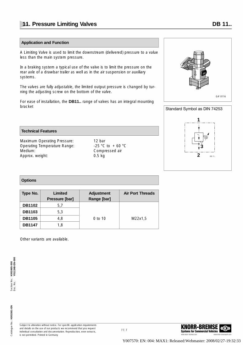
Type No. Limited Adjustment Air Port ThreadsPressure [bar] Range [bar]
DB1102 5,7
DB1103 5,3
DB1105 4,8 0 to 10 M22x1,5
DB1147 1,8
11. Pressure Limiting Valves DB 11..
www.knorr-bremse.com www.knorr-bremsesfn.com
KNORR-BREMSESystems for Commercial Vehicles
Subject to alteration without notice. For specific application requirementsand details on the use of our products we recommend that you request individual consultation and documentation. Reproduction, even extracts,is not permitted. Printed in Germany
11.1
Cat
alog
ue N
o.: K
0015
61-E
NS
ectio
n N
o.:
K00
2465
-000
Doc
. No.
:Y
0113
48-E
N-0
00
Application and Function
A Limiting Valve is used to limit the downstream (delivered) pressure to a valueless than the main system pressure.
In a braking system a typical use of the valve is to limit the pressure on therear axle of a drawbar trailer as well as in the air suspension or auxiliarysystems.
The valves are fully adjustable, the limited output pressure is changed by tur-ning the adjusting screw on the bottom of the valve.
For ease of installation, the DB11.. range of valves has an integral mountingbracket
Technical Features
Maximum Operating Pressure: 12 barOperating Temperature Range: -25 °C to + 60 °CMedium: Compressed airApprox. weight: 0.5 kg
Options
KNORR-BREMSE
KNORR-BREMSE
GrF 0116
Standard Symbol as DIN 74253
1
2
3
DB 11..
Other variants are available.
Y007570: EN: 004: MAX1: Released:Webmaster: 2008/02/27-19:32:33

11. Pressure Limiting Valves DB 11..
www.knorr-bremse.com www.knorr-bremsesfn.com
KNORR-BREMSESystems for Commercial Vehicles
Subject to alteration without notice. For specific application requirementsand details on the use of our products we recommend that you request individual consultation and documentation. Reproduction, even extracts,is not permitted. Printed in Germany
11.2
Cat
alog
ue N
o.: K
0015
61-E
NS
ectio
n N
o.:
K00
2465
-000
Doc
. No.
:Y
0113
48-E
N-0
00
9 2
X
3
66m
ax 21
118
SW 10
17
50
M22
x1,5
17
55
58
74
M22x1,5
View "X"
VF 00075/48 EN
DB1102DB1103DB1105DB1147
Air Ports:
1 = Supply 2 = Delivery 3 = Exhaust
48 1
Adjustment screw
Dimensions
Y007570: EN: 004: MAX1: Released:Webmaster: 2008/02/27-19:32:33

Type No. Air Port Threads Control Button
AE4257 M22x1,5 Round, black
12. Release Valves AE4257
Release Valves for the Front Axle of Drawbar Trailers
www.knorr-bremse.com www.knorr-bremsesfn.com
KNORR-BREMSESystems for Commercial Vehicles
Subject to alteration without notice. For specific application requirementsand details on the use of our products we recommend that you request individual consultation and documentation. Reproduction, even extracts,is not permitted. Printed in Germany
12.1
Cat
alog
ue N
o.: K
0015
61-E
NS
ectio
n N
o.:
K00
2466
-001
Doc
. No.
:Y
0113
49-E
N-0
01
KNORR-BREMSE
1212 2
1111
Standard Symbol as DIN ISO 1219
2
1211 AE 4257
Application and Function
The Release Valve, also called Manoeuvring Valve, is used on drawbar trailers.
This Valve allows front axle service brakes of an un-coupled, and thereforebraked trailer to be released for manoeuvring/ "shunting" purposes by pushingin the control button.
By pulling out the control button, air is able to once again pass from the trailerreservoir to the brake chambers and the brakes are therefore re-applied.
When the trailer is re-coupled, connection of the Supply (Red) Line will causethe control button to automatically return to the ‘Drive’ position.
Technical Features:
Maximum Operating Pressure: 8,5 barOperating Temperature Range: -40 °C to +80 °CMedium: Compressed airApprox. weight: 0,5 kg
Options
GrF 0072
Y007570: EN: 004: MAX1: Released:Webmaster: 2008/02/27-19:32:33

12. Release Valves AE 4257
Release Valves for the Front Axle of Drawbar Trailers
www.knorr-bremse.com www.knorr-bremsesfn.com
KNORR-BREMSESystems for Commercial Vehicles
Subject to alteration without notice. For specific application requirementsand details on the use of our products we recommend that you request individual consultation and documentation. Reproduction, even extracts,is not permitted. Printed in Germany
12.2
Cat
alog
ue N
o.: K
0015
61-E
NS
ectio
n N
o.:
K00
2466
-001
Doc
. No.
:Y
0113
49-E
N-0
01
AE4257
Dimensions
Y007570: EN: 004: MAX1: Released:Webmaster: 2008/02/27-19:32:33

12. Release Valves AE 4211
Release Valves for the Front Axle of Drawbar Trailers, for use with AE4311
www.knorr-bremse.com www.knorr-bremsesfn.com
KNORR-BREMSESystems for Commercial Vehicles
Subject to alteration without notice. For specific application requirementsand details on the use of our products we recommend that you request individual consultation and documentation. Reproduction, even extracts,is not permitted. Printed in Germany
12.3
Cat
alog
ue N
o.: K
0015
61-E
NS
ectio
n N
o.:
K00
2466
-001
Doc
. No.
:Y
0113
49-E
N-0
01
Standard Symbol as DIN ISO 1219
Application and Function
This valve is used on drawbar trailers in combination with the Park / ShuntValve AE4311. Uncoupling the Supply Line causes the front axle ofthe drawbar trailer to be braked by pressurising the service brake actuators.
By pushing in the control button of the Release Valve the brake of the frontaxle is released allowing the drawbar to be manoeuvred. By pulling out thebutton the brake on the front axle will be re-applied.
If the Supply (Red) Line of the trailer is re-coupled and pressurised, theactuating valve automatically switches the Release Valve into driving position.
Technical Features
Maximum Operating Pressure: max. 10 barOperating Temperature Range: -40°C to +80°CMedium: Compressed airMounting Position: 1)
Approximate Weight: 1 kg
Product overview
Max. Tightening torques:M16x1,5: 45 NmM8: 20 Nm
VF00199_299
Type No. Part No. Air Port Mounting FurtherThreads Thread technical (internal) details
AE4211 K006368 M16x1,5 M8 Y018659
1) Mainly in the manoeuvring area of the drawbar, port 3 should point down!
Y007570: EN: 004: MAX1: Released:Webmaster: 2008/02/27-19:32:33

12. Release Valves AE 4211
Release Valves for the Front Axle of Drawbar Trailers, for use with AE4311
www.knorr-bremse.com www.knorr-bremsesfn.com
KNORR-BREMSESystems for Commercial Vehicles
Subject to alteration without notice. For specific application requirementsand details on the use of our products we recommend that you request individual consultation and documentation. Reproduction, even extracts,is not permitted. Printed in Germany
12.4
Cat
alog
ue N
o.: K
0015
61-E
NS
ectio
n N
o.:
K00
2466
-001
Doc
. No.
:Y
0113
49-E
N-0
01
Dimensions
AE4211Ports:
11 Supply from the air reservoir12 Supply from the service brake line
2 Delivery41 Control signal from the combined manoeuvring valve 42 Control signal from the supply pressure
3 Exhaust
Installation Example, 2-Axle Drawbar Trailer with Spring Brakes and TEBS
VF00075/284 EN
Y007570: EN: 004: MAX1: Released:Webmaster: 2008/02/27-19:32:33

13. Trailer Manoeuvring (Shunt) Valves AE4261
www.knorr-bremse.com www.knorr-bremsesfn.com
KNORR-BREMSESystems for Commercial Vehicles
Subject to alteration without notice. For specific application requirementsand details on the use of our products we recommend that you request individual consultation and documentation. Reproduction, even extracts,is not permitted. Printed in Germany
13.1
Cat
alog
ue N
o.: K
0015
61-E
NS
ectio
n N
o.:
K00
2467
-000
Doc
. No.
:Y
0113
50-E
N-0
00
Type No. Air Port Threads Mounting Control Button
AE4261 M16x1,5In Supply Line or Round, black
via a Mounting Plate with function symbol
Type No. Lock in place Non- return Valve(in end position) (port 12)
AE4261 With Without
Standard Symbol as DIN ISO 1219
2
AE 42141211
VF00119_170
Application and Function
The Trailer Manoeuvring Valve allows the service brakes of an un-coupled trai-ler to be released for manoeuvring/ "shunting" purposes by pushing in theControl Button.
In the absence of Supply (Red) Line pressure to the trailer, depressing theControl Button allows air pressure from the Trailer Reservoir to feed the RelayEmergency Valve thus automatically releasing the service brakes.
When the trailer is re-coupled, connection of the Supply (Red) Line will causethe Control Button to automatically return to the ‘Drive’ position.
Caution: Always ensure that after manoeuvring, the Valve´s buttonis pulled out and the Trailer Park Valve is correctly applied.
Technical Features
Maximum Operating Pressure: 8,0 barOperating Temperature Range: -40 °C to +80 °CWay Through: 4,5mmMedium: Compressed airApprox. weight: 0,5 kg
Options
Y007570: EN: 004: MAX1: Released:Webmaster: 2008/02/27-19:32:33

13. Trailer Manoeuvring (Shunt) Valves AE4261
www.knorr-bremse.com www.knorr-bremsesfn.com
KNORR-BREMSESystems for Commercial Vehicles
Subject to alteration without notice. For specific application requirementsand details on the use of our products we recommend that you request individual consultation and documentation. Reproduction, even extracts,is not permitted. Printed in Germany
13.2
Cat
alog
ue N
o.: K
0015
61-E
NS
ectio
n N
o.:
K00
2467
-000
Doc
. No.
:Y
0113
50-E
N-0
00
AE4261
Dimensions
Y007570: EN: 004: MAX1: Released:Webmaster: 2008/02/27-19:32:33

14. Trailer Park Valves AE4262, AE4264
www.knorr-bremse.com www.knorr-bremsesfn.com
KNORR-BREMSESystems for Commercial Vehicles
Subject to alteration without notice. For specific application requirementsand details on the use of our products we recommend that you request individual consultation and documentation. Reproduction, even extracts,is not permitted. Printed in Germany
14.1
Cat
alog
ue N
o.: K
0015
61-E
NS
ectio
n N
o.:
K00
2468
-000
Doc
. No.
:Y
0113
51-E
N-0
00
Type No. Air Port Threads Mounting Control Button
AE4262In Supply Line Red, square,
M16x1,5 or via withAE4264 a Mounting Plate function symbol
Standard Symbol as DIN ISO 1219
AE4262
AE4264
2
123/11 AE 4262
Application and Function
The Trailer Park Valve operates the parking brake function of trailers equippedwith Spring Brake Actuators.Whether coupled or uncoupled, the button must always be pulled out to cor-rectly park the trailer.By pushing in the Control Button, the Spring Portions of the Spring BrakeActuators are supplied with air so that the parking brake is released.
Caution: Always ensure that the red Control Button is pulled out and thetrailer is correctly parked, before coupling or uncoupling the trailer.
Technical Features
Maximum Operating Pressure: 8,0 barOperating Temperature Range: -40 °C to +80 °CWay Through: 4,5 mm (for AE4262)
3,8 mm (for AE4264)Medium: Compressed airApprox. weight: 0,5 kg
Options
Type No. Lock in place Non- return Valve
(in end positions) (port 12)
AE4262 Without
AE4264 WithWith
GrF 0534
2
123/11AE 4264
Y007570: EN: 004: MAX1: Released:Webmaster: 2008/02/27-19:32:33

14. Trailer Park Valves AE4262, AE4264
www.knorr-bremse.com www.knorr-bremsesfn.com
KNORR-BREMSESystems for Commercial Vehicles
Subject to alteration without notice. For specific application requirementsand details on the use of our products we recommend that you request individual consultation and documentation. Reproduction, even extracts,is not permitted. Printed in Germany
14.2
Cat
alog
ue N
o.: K
0015
61-E
NS
ectio
n N
o.:
K00
2468
-000
Doc
. No.
:Y
0113
51-E
N-0
00
AE4262AE4264
Dimensions
Y007570: EN: 004: MAX1: Released:Webmaster: 2008/02/27-19:32:33

Type No. Air Port Threads design
AE2100 M22x1,5 With exhaust
AE2110 M22x1,5 With exhaust and two shut-off positions
15. Shut-Off Valves AE21..
www.knorr-bremse.com www.knorr-bremsesfn.com
KNORR-BREMSESystems for Commercial Vehicles
Subject to alteration without notice. For specific application requirementsand details on the use of our products we recommend that you request individual consultation and documentation. Reproduction, even extracts,is not permitted. Printed in Germany
15.1
Cat
alog
ue N
o.: K
0015
61-E
NS
ectio
n N
o.:
K00
2469
-000
Doc
. No.
:Y
0113
52-E
N-0
00
KNORR-BREMSE
GrF 0064
Standard Symbol as DIN 74253
21
AE 2100
3
Application and Function
The Shut-Off Valve is used in air systems to control the supply of air.
The valve is manually operated via a lever which, when rotated, shuts off thedelivery pressure from the valve.
The delivered pressure exhausts back through the Valve to atmosphere.
Technical Features
Maximum Operating Pressure: 10,0 barOperating Temperature Range: -40 °C to +80 °CMedium: Compressed airApprox. weight: 0,4 kg
Options
Y007570: EN: 004: MAX1: Released:Webmaster: 2008/02/27-19:32:33

15. Shut-Off Valves AE21..
www.knorr-bremse.com www.knorr-bremsesfn.com
KNORR-BREMSESystems for Commercial Vehicles
Subject to alteration without notice. For specific application requirementsand details on the use of our products we recommend that you request individual consultation and documentation. Reproduction, even extracts,is not permitted. Printed in Germany
15.2
Cat
alog
ue N
o.: K
0015
61-E
NS
ectio
n N
o.:
K00
2469
-000
Doc
. No.
:Y
0113
52-E
N-0
00
95 1 2
14
M22
x1,5
M22
x1,5
14
4
12
109
84
47
52
26
105
ø9,5 Direction of Air Flow when pressure increases(when lever in shown position)
Operation Range 90°Move lever through 90° to fully shut valve and vent delivered air (Port 2) to atmosphere.
Valve shown in air delivery position(Lever in longitudinal axis)
VF 00075/80 EN
Air Ports:
1 = Supply2 = Delivery3 = Exhaust
AE2100
28
56
3
AE2100
Dimensions
M22
x1,5
M22
x1,5
87
28
48
6528
12
110
1 2
3
X
52
26
60
84
ø10
51
38
90°Operation
(see note *)
View X
90°Operation(see note *)
VF 00075/81 EN
AE2110
Air Ports:
1 = Supply2 = Delivery3 = Exhaust
Valve shown in air delivery position(Lever in longitudinal axis)
*) Move lever through 90° to fully shut valve and vent delivered air (Port 2) to atmosphere.
AE2110
Y007570: EN: 004: MAX1: Released:Webmaster: 2008/02/27-19:32:33

16. Combined Manoeuvring (Park / Shunt) Valves AE424.
www.knorr-bremse.com www.knorr-bremsesfn.com
KNORR-BREMSESystems for Commercial Vehicles
Subject to alteration without notice. For specific application requirementsand details on the use of our products we recommend that you request individual consultation and documentation. Reproduction, even extracts,is not permitted. Printed in Germany
16.1
Cat
alog
ue N
o.: K
0015
61-E
NS
ectio
n N
o.:
K00
2470
-000
Doc
. No.
:Y
0113
53-E
N-0
00
KNORR-DAHL
P
P
P
Standard Symbol as DIN ISO 1219
AE4246 - II36125AE4247 - II36129
AE4246 - II36126AE4247 - II36131
21 11 22
31
AE 4229
Type No. Part No. Air Port Threads Non-Return Information Plate1 and 3 Valve & Security Pin
AE4246 II36125 M22x1,5 Without With AE4246 II36126 M22x1,5 With WithAE4247 II36129 M16x1,5 Without WithAE4247 II36131 M16x1,5 With With
21 11 22
31
AE 4247
Function
The Combined Manoeuvring Valve incorporates the Park and Shuntfunctions for use on Trailers equipped with Spring Brake Actuators.
The Park Valve operates the trailer's parking brake function by supplying and releasing pressure to the Spring Portions of the SpringBrake Actuators. When the Trailer is parked, the security pin should beinserted behind the Red Park Button to avoid accidental release of theSpring Brakes. Whether coupled or uncoupled, the Red Button mustbe pulled out to correctly park the Trailer on its Spring Brakes.
The Shunt Valve allows the Service Brakes of an uncoupled trailer to bereleased for manoeuvring purposes. In the absence of Supply (Red)Line pressure to the trailer, depressing the Red Button to release thepark brake and then depressing the Black Button allows air pressurefrom the Trailer Reservoir to feed the Emergency Valve and therebyrelease the Service Brakes. If the Black Button is left depressed, whenthe trailer is re-coupled, air pressure in the Supply (Red) Line will re-setthe button so that the Relay Emergency Valve is once again suppliedby towing vehicle pressure.
Versions of the Combined Manoeuvring Valve are available with an inte-gral Non-Return Valve. This has been introduced to overcome the problem of Spring Brakes starting to apply in the event of reduced Trailer Reservoir pressure during prolonged ABS cycling.
When using a Valve with integral Non-Return Valve, extreme careshould be taken to ensure that the trailer is correctly parked using theRed Button. If the trailer is parked on Service air pressure, e.g. onlySupply (Red) line disconnected, and the Trailer air pressure depletes,the Spring Brakes cannot apply as the Non-Return Valve holds thepressure in the Spring Portions.
Caution: Always ensure that the Red Button is pulled out and thetrailer is correctly parked, before coupling or uncoupling the trailer.
Technical Features
Operating Pressure: 8,5 barMaximum Operating Pressure: 10 barOperating Temperature Range: -40 ºC to +80 ºCMedium: Compressed AirApprox. weight: 0,9 kgSymbol label: 3EB02234
Options
Note: The manoeuvring valve (black button) has the Type No. AE4233
Y007570: EN: 004: MAX1: Released:Webmaster: 2008/02/27-19:32:33

37
2x M
8
32
30 30
30
60
37
66
50
35
redblack
12
3x M16x1,5
21 11 2231
86
102
43
3876
60 6099 99
REB01504/1
VF 00075/16 EN
Air ports: 1 = Inlet "supply line" 11 = Inlet "reservoir" 21 = Delivery "Relay emergency valve" 22 = Delivery "Spring brake" 3 = Exhaust
KNORR-DAHL
release position
braking position Stro
ke =
18m
m
AE4246AE4247
16. Combined Manoeuvring (Park / Shunt) Valves AE424.
www.knorr-bremse.com www.knorr-bremsesfn.com
KNORR-BREMSESystems for Commercial Vehicles
Subject to alteration without notice. For specific application requirementsand details on the use of our products we recommend that you request individual consultation and documentation. Reproduction, even extracts,is not permitted. Printed in Germany
16.2
Cat
alog
ue N
o.: K
0015
61-E
NS
ectio
n N
o.:
K00
2470
-000
Doc
. No.
:Y
0113
53-E
N-0
00
Dimensions
Y007570: EN: 004: MAX1: Released:Webmaster: 2008/02/27-19:32:33

17. Park / Shunt Valves with Integrated Emergency Function AE431.
www.knorr-bremse.com www.knorr-bremsesfn.com
KNORR-BREMSESystems for Commercial Vehicles
Subject to alteration without notice. For specific application requirementsand details on the use of our products we recommend that you request individual consultation and documentation. Reproduction, even extracts,is not permitted. Printed in Germany
17.1
Cat
alog
ue N
o.: K
0015
61-E
NS
ectio
n N
o.:
K00
2471
-001
Doc
. No.
:Y
0113
54-E
N-0
01
VF 00199_51
Standard Symbol as DIN ISO 1219
AE4310AE4311
Operation of the parking brake - red button -
Parking brake released
Unlock
Pull out
Parking brake applied
Function:
The Park / Shunt Valve with Integrated Emergency Function is used on trai-lers that are equipped with Spring Brakes. It is connected to the Supply (Red)Line and enables the manual release and application of the trailer SpringBrakes.Additionally, the AE431. has an integrated emergency function and in theevent of loss of pressure in the trailer Supply (Red) Line resulting fromuncoupling or failure of the Supply Line whilst driving, this feature will automatically apply the trailer’s Spring Brakes by exhausting their air supplyand not by applying the trailer’s service brakes as with traditional RelayEmergency Valves (REV). This means there is no longer a need for a separateRelay Emergency Valve and ensures that the vehicle is safely braked using theSpring Brakes, especially when the air pressure depletes.An additional benefit of this functionality is that the Spring Brakes are automa-tically applied every time the trailer is uncoupled. This helps the Spring Brakesto retain their output force since the springs do not remain compressed forlong periods of time.
This feature of the valve also reduces the possibility of air leakage when thetrailer is uncoupled.In contrast to trailers with a REV, nearly all pipes and hoses are exhaustedgiving reduced risk of reservoir air leakage.
Both buttons of the AE431. control the Spring Brakes
The red button is used to operate the parking brake. It has a safety functionthat protects against unintentional operation and must be operated by pullingthe locking sleeve.
The black button is used for manoeuvring the uncoupled trailer. However, incontrast with conventional release valves, it operates the Spring Brakes. Note,it can only be pushed in when the trailer is uncoupled and re-connection ofthe Supply (Red) Line will cause it to automatically return to the driving position.
The mounting plate Z006845 (see page 17.2) explains the operation of thetwo buttons.
Technical Features
Operating Pressure: 8,5 barMaximum Operating Pressure: 10 barOperating Temperature Range: -40 °C to +80 °CMedium: Compressed AirApprox. weight: 1,45 kg
Service Brake Priority:When charging the reservoir the service brake is given priority up to a pressureof 3,0 bar.
Emergency function:In the event of a pressure drop at port 1 below 2,6 bar, the spring brakes areautomatically applied.
1-2
21
AE43..
3
Y007570: EN: 004: MAX1: Released:Webmaster: 2008/02/27-19:32:33

17. Park / Shunt Valves with Integrated Emergency Function AE431.
www.knorr-bremse.com www.knorr-bremsesfn.com
KNORR-BREMSESystems for Commercial Vehicles
Subject to alteration without notice. For specific application requirementsand details on the use of our products we recommend that you request individual consultation and documentation. Reproduction, even extracts,is not permitted. Printed in Germany
17.2
Cat
alog
ue N
o.: K
0015
61-E
NS
ectio
n N
o.:
K00
2471
-001
Doc
. No.
:Y
0113
54-E
N-0
01
Brake released Brake applied
Black button- Manoeuvring -
(only when the vehicle is uncoupled)
Red button- Parking -
The plate Z006845 can be ordered separately, or delivered with the Park / ShuntValve AE431. (for installation dimensions see page 17.3).
Mounting Plate
Type No. Part No. Air Port Threads Exhaust
AE4310 II36229 M16x1,5 - DIN 3852 With SilencerAE4311 K000896 M16x1,5 - DIN 3852 With rubber flap
With rubber flapAE4311 K001664 M16x1,5 - DIN 3852
With Plate Z006845
Product Overview
Y007570: EN: 004: MAX1: Released:Webmaster: 2008/02/27-19:32:33

17. Park / Shunt Valves with Integrated Emergency Function AE431.
www.knorr-bremse.com www.knorr-bremsesfn.com
KNORR-BREMSESystems for Commercial Vehicles
Subject to alteration without notice. For specific application requirementsand details on the use of our products we recommend that you request individual consultation and documentation. Reproduction, even extracts,is not permitted. Printed in Germany
17.3
Cat
alog
ue N
o.: K
0015
61-E
NS
ectio
n N
o.:
K00
2471
-001
Doc
. No.
:Y
0113
54-E
N-0
01
Dimensions
AE4310AE4311
Y007570: EN: 004: MAX1: Released:Webmaster: 2008/02/27-19:32:33

17. Park / Shunt Valves with Integrated Emergency Function AE431.
www.knorr-bremse.com www.knorr-bremsesfn.com
KNORR-BREMSESystems for Commercial Vehicles
Subject to alteration without notice. For specific application requirementsand details on the use of our products we recommend that you request individual consultation and documentation. Reproduction, even extracts,is not permitted. Printed in Germany
17.4
Cat
alog
ue N
o.: K
0015
61-E
NS
ectio
n N
o.:
K00
2471
-001
Doc
. No.
:Y
0113
54-E
N-0
01
Installation example AE4311 with EBS
Dimensions of the Mounting Plate
60
120
95
190
43
86 110
40±0,5
8,5±
0,2
R10
VF 00075/167
Item Designation
1 Park / Shunt Valve AE4311
2 EBS-Module ES2...
3 Reservoir VB....
4 Brake Actuator BS.... or BX.... or BZ....
5 Coupling Head with filter, Supply - Red - KU14..
6 Coupling Head with filter, Control - Yellow - KU14..
Y007570: EN: 004: MAX1: Released:Webmaster: 2008/02/27-19:32:33
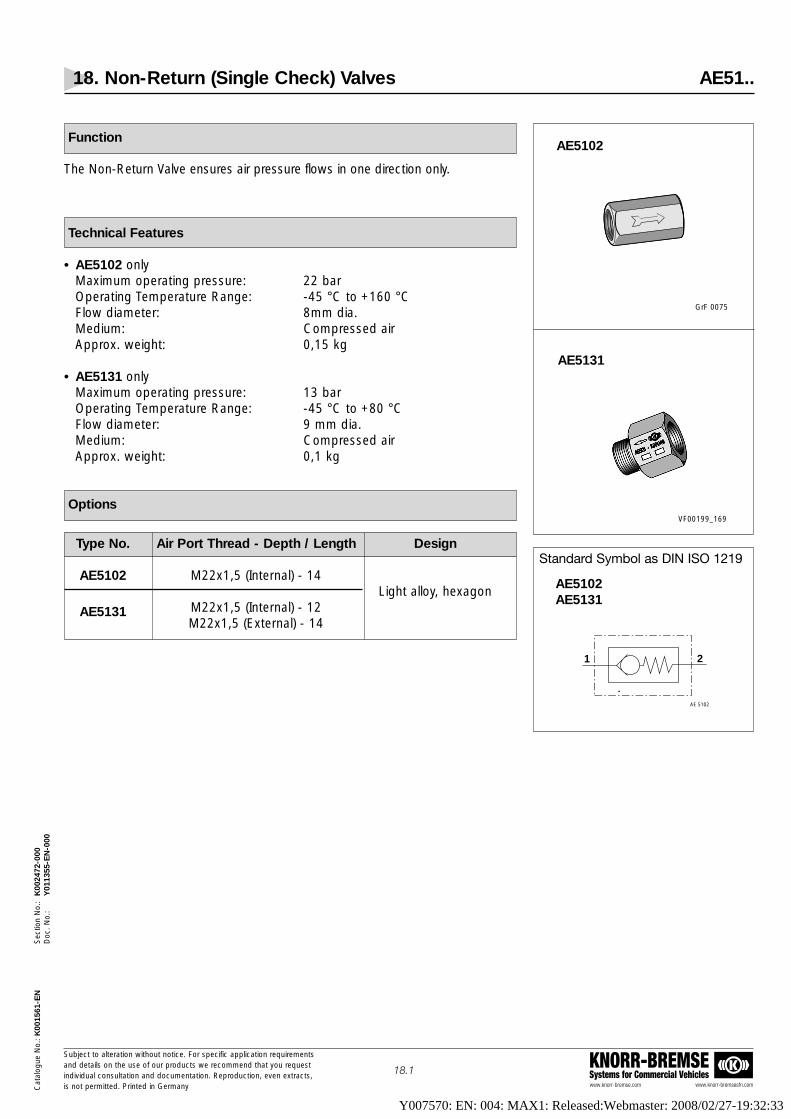
18. Non-Return (Single Check) Valves AE51..
www.knorr-bremse.com www.knorr-bremsesfn.com
KNORR-BREMSESystems for Commercial Vehicles
Subject to alteration without notice. For specific application requirementsand details on the use of our products we recommend that you request individual consultation and documentation. Reproduction, even extracts,is not permitted. Printed in Germany
18.1
Cat
alog
ue N
o.: K
0015
61-E
NS
ectio
n N
o.:
K00
2472
-000
Doc
. No.
:Y
0113
55-E
N-0
00
Type No. Air Port Thread - Depth / Length Design
AE5102 M22x1,5 (Internal) - 14Light alloy, hexagon
AE5131 M22x1,5 (Internal) - 12M22x1,5 (External) - 14
GrF 0075
Standard Symbol as DIN ISO 1219
VF00199_169
AE5102
AE5131
AE 5102
21
AE5102AE5131
Function
The Non-Return Valve ensures air pressure flows in one direction only.
Technical Features
• AE5102 only Maximum operating pressure: 22 barOperating Temperature Range: -45 °C to +160 °CFlow diameter: 8mm dia.Medium: Compressed airApprox. weight: 0,15 kg
• AE5131 only Maximum operating pressure: 13 barOperating Temperature Range: -45 °C to +80 °CFlow diameter: 9 mm dia.Medium: Compressed airApprox. weight: 0,1 kg
Options
Y007570: EN: 004: MAX1: Released:Webmaster: 2008/02/27-19:32:33

18. Non-Return (Single Check) Valves AE51..
www.knorr-bremse.com www.knorr-bremsesfn.com
KNORR-BREMSESystems for Commercial Vehicles
Subject to alteration without notice. For specific application requirementsand details on the use of our products we recommend that you request individual consultation and documentation. Reproduction, even extracts,is not permitted. Printed in Germany
18.2
Cat
alog
ue N
o.: K
0015
61-E
NS
ectio
n N
o.:
K00
2472
-000
Doc
. No.
:Y
0113
55-E
N-0
00
72
14
SW 32
1 2
1
3 4
2
Air ports:
1 Inlet2 Delivery3 valve cone4 pressure spring
VF 00075/89 EN
AE5102
Dimensions
AE5102
AE5131
Y007570: EN: 004: MAX1: Released:Webmaster: 2008/02/27-19:32:33

19. Double Check Valves AE41.., 295358
www.knorr-bremse.com www.knorr-bremsesfn.com
KNORR-BREMSESystems for Commercial Vehicles
Subject to alteration without notice. For specific application requirementsand details on the use of our products we recommend that you request individual consultation and documentation. Reproduction, even extracts,is not permitted. Printed in Germany
19.1
Cat
alog
ue N
o.: K
0015
61-E
NS
ectio
n N
o.:
K00
2473
-000
Doc
. No.
:Y
0113
56-E
N-0
00
Type No. Air Port Threads Design
AE4100 M22x1,5 With mounting
AE4105 M22x1,5 Without mounting, short design
295358 M16x1,5 With mounting
GrF 0066
Standard Symbol as DIN ISO 1219
2
AE 4100
1211
Function
A Double Check Valve can accept signal pressures from two separatesources, the higher pressure will be delivered and the lower pressurewill be isolated.
The Double Check Valve is often used as an anti-compounding devicefor trailers equipped with Spring Brake Actuators.
If a trailer is parked (no pressure in Spring Portions of the Spring BrakeActuators) and the service brake is subsequently applied, the DoubleCheck Valve directs service pressure into the Spring Portions of theSpring Brake Actuators. This eliminates the compounding force of asimultaneous parking brake and service brake application which candamage the trailer's foundation brakes.
Technical Features
Maximum operating pressure: 10 barFlow diameter:
AE4100 8-16 mm AE4105 14 mm295358 11 mm
Minimal differential pressure: ∆ 0,15 barOperating Temperature Range: -40 ºC to +80 ºCMedium: Compressed airApprox. weight: 0,15 kg
Options
Y007570: EN: 004: MAX1: Released:Webmaster: 2008/02/27-19:32:33

Cat
alog
ue N
o.: K
0015
61-E
NS
ectio
n N
o.:
K00
2473
-000
Doc
. No.
:Y
0113
56-E
N-0
00
www.knorr-bremse.com www.knorr-bremsesfn.com
KNORR-BREMSESystems for Commercial Vehicles
Subject to alteration without notice. For specific application requirementsand details on the use of our products we recommend that you request individual consultation and documentation. Reproduction, even extracts,is not permitted. Printed in Germany
19.2
19. Double Check Valves AE41.., 295358
M22x1,5
M22
x1,5
M22
x1,5
32
ø11,
5
M22
x1,5
M22
x1,5
31,5
SW
3012
1212
12
15
76110
55
59
2
12 11
SW32
SW30
M22
x1,5
15 15
36
X
View "X"
Air ports:
11 = Inlet12 = Inlet 2 = Delivery
212 11
VF 00075/82 EN
AE 4100 AE 4105
Dimensions
AE4100
295358
AE4105
Y007570: EN: 004: MAX1: Released:Webmaster: 2008/02/27-19:32:33

20. Relay Valves RE11..
www.knorr-bremse.com www.knorr-bremsesfn.com
KNORR-BREMSESystems for Commercial Vehicles
Subject to alteration without notice. For specific application requirementsand details on the use of our products we recommend that you request individual consultation and documentation. Reproduction, even extracts,is not permitted. Printed in Germany
20.1
Cat
alog
ue N
o.: K
0015
61-E
NS
ectio
n N
o.:
K00
2474
-000
Doc
. No.
:Y
0113
57-E
N-0
00
Type No. A i r P o r t T h r e a d s1 2 4
RE1121M22x1,5
M16x1,5M16x1,5
RE1131 M22x1,5
GrF 0196
Standard Symbol as DIN ISO 1219
2
3
4
1
RE 11..
0 1 2 3 4 5 6 7 7,5
1
2
3
4
5
6
77,5
VF 00075/179 EN
≤ 0,2
2
4
= Delivery Pressure [bar]
= Signal Pressure [bar]
24
Performance Chart
Function
In response to an air pressure signal from a control valve, the Relay Valve willspeed up brake applications by providing rapid and precise control of a largevolume of air.
Technical Features
Maximum operating pressure: 8,5 barOperating Temperature Range: -40 ºC to +80 ºCFlow Diameter: 13mmMedium: Compressed airApprox. weight: 1,1 kg
Options
Other types are available on request.
Y007570: EN: 004: MAX1: Released:Webmaster: 2008/02/27-19:32:33

Cat
alog
ue N
o.: K
0015
61-E
NS
ectio
n N
o.:
K00
2474
-000
Doc
. No.
:Y
0113
57-E
N-0
00
www.knorr-bremse.com www.knorr-bremsesfn.com
KNORR-BREMSESystems for Commercial Vehicles
Subject to alteration without notice. For specific application requirementsand details on the use of our products we recommend that you request individual consultation and documentation. Reproduction, even extracts,is not permitted. Printed in Germany
20.2
20. Relay Valves RE11..
Dimensions
60
52
SW30
max
. 10
2550
,5
37,5
20
46
94,5
SW 27
22
3
75
M8SW 32
SW 32
52
104
20
VF 00075/178 EN
1
4
Air Ports:
1 = Supply 2 = Delivery 3 = Exhaust 4 = Signal
RE1121RE1131
141414
14
100
RE1121RE1131
Installation
1) Mount the Relay Valve upright in a protected position and ensure that the piping runs do not allow moisture to drain into the valve.
2) To help installation, the top cover may be turned in 90° steps so as to point in any one of four directions. This enables the pipework to be run clear of any local obstructions.
3) Never block the exhaust port or allow it to be close to any part of the vehicle.
Y007570: EN: 004: MAX1: Released:Webmaster: 2008/02/27-19:32:33

21. Quick Release Valves RE21..
www.knorr-bremse.com www.knorr-bremsesfn.com
KNORR-BREMSESystems for Commercial Vehicles
Subject to alteration without notice. For specific application requirementsand details on the use of our products we recommend that you request individual consultation and documentation. Reproduction, even extracts,is not permitted. Printed in Germany
21.1
Cat
alog
ue N
o.: K
0015
61-E
NS
ectio
n N
o.:
K00
2475
-000
Doc
. No.
:Y
0113
58-E
N-0
00
Function
A Quick Release Valve is used to speed up the exhaust of a large volume of air.
The Valve is generally used in the supply to the Spring Portion of Spring BrakeActuators to speed up the application of the trailer parking brake.
Technical Features
Maximum operating pressure: 10 barOperating Temperature Range: -40 °C to +80 °CMedium: Compressed airApprox. weight: 0,4 kg
Options
2 2
GrF 0197
Standard Symbol as DIN ISO 1219
1 3
2
RE 2118
Type No. Air Port Threads1 2
RE21081)
M22x1,5 M22x1,5
RE2118
1) Residual delivery pressure exhausts through port 1
Y007570: EN: 004: MAX1: Released:Webmaster: 2008/02/27-19:32:33

21. Quick Release Valves RE21..
www.knorr-bremse.com www.knorr-bremsesfn.com
KNORR-BREMSESystems for Commercial Vehicles
Subject to alteration without notice. For specific application requirementsand details on the use of our products we recommend that you request individual consultation and documentation. Reproduction, even extracts,is not permitted. Printed in Germany
21.2
Cat
alog
ue N
o.: K
0015
61-E
NS
ectio
n N
o.:
K00
2475
-000
Doc
. No.
:Y
0113
58-E
N-0
00
Dimensions
Air Port:
1 = Inlet 2 = Delivery 3 = Exhaust
2 2
65
71,5
43,5
87
SW30
SW30
31
H
VF 00075/57 EN
ø30
39
ø30
7,5
ø30
RE21081)
RE2118
1) Residual delivery pressure exhausts through port 1
3
9,5
38
14 14
M22
x1,5
M22
x1,5
M22x1,5
14
ø30
1340
1
Installation instructions:
1) Mount the Quick Release Valve in an upright position, exhaust port 3 facing downwards.
2) Never block the exhaust port or allow it to be close to any part of the vehicle.
Y007570: EN: 004: MAX1: Released:Webmaster: 2008/02/27-19:32:33

Cat
alog
ue N
o.: K
0015
61-E
NS
ectio
n N
o.:
K00
2476
-002
Doc
. No.
:Y
0113
59-E
N-0
02
www.knorr-bremse.com www.knorr-bremsesfn.com
KNORR-BREMSESystems for Commercial Vehicles
Subject to alteration without notice. For specific application requirementsand details on the use of our products we recommend that you request individual consultation and documentation. Reproduction, even extracts,is not permitted. Printed in Germany
22.1
22. Air Reservoirs and accessory parts VB...., KR...., BS....
Air Reservoirs (Steel)
Function
Air Reservoirs are used to store the compressed air for the vehicle air brakingand auxilliary systems. They are available in steel - see this page, or aluminium - see page 22.2 and 22.3
Note: aluminium reservoirs are approximately 60% lighter than steel reservoirs of the same capacity.
Technical Features
Pressure rating: EN 286-2, with CE-symbolMaximum Operating Pressure: 12,5 barOperating Temperature Range: -40 °C to +100 °C Medium: Compressed airMaterial: Steel, black primedAir Port Threads: M22x1,5; DIN 74281
Options
GrF 0259
Type No. Reservoir Dimensiondiameter [mm]
VB1206 206VB1246 246VB1276 276VB1310 310VB1396 396
Type No. Volume D L1 Weight[l] [mm] [mm] [kg]
VB3301/206 10 206 370 4,8VB33015/206 15 206 530 6,4VB3302/206 20 206 690 8,2VB3302/246 20 246 500 7,3VB3302/276 20 276 416 7,0VB3303/246 30 246 720 10,0VB3303/276 30 276 585 9,4VB3337/246 37 246 869 11,9VB3304/246 40 246 940 12,8VB3304/276 40 276 760 11,8VB3304/310 40 310 620 11,3VB3306/246 60 246 1369 18,1VB3306/276 60 276 1110 16,7VB3306/310 60 310 895 15,6VB3306/396 60 396 580 16,8VB3308/396 80 396 750 21,1VB33085/276 85 276 1543 23,8VB3310/396 100 396 915 25,4VB3312/396 120 396 1089 29,4
Drain Valve: EE1100
Fixing Straps are available to suit each reservoir diameter:
Y007570: EN: 004: MAX1: Released:Webmaster: 2008/02/27-19:32:33

Cat
alog
ue N
o.: K
0015
61-E
NS
ectio
n N
o.:
K00
2476
-002
Doc
. No.
:Y
0113
59-E
N-0
02
www.knorr-bremse.com www.knorr-bremsesfn.com
KNORR-BREMSESystems for Commercial Vehicles
Subject to alteration without notice. For specific application requirementsand details on the use of our products we recommend that you request individual consultation and documentation. Reproduction, even extracts,is not permitted. Printed in Germany
22.2
22. Air Reservoir and accessory parts VB...., KR...., BS....
Air Reservoirs (Aluminium)
Function
Air Reservoirs are used to store the compressed air for the vehicle air brakingand auxilliary systems. They are available in aluminium - see this page and page 22.3, or steel - seepage 22.1.Note: aluminium reservoirs are approximately 60% lighter than steel
reservoirs of the same capacity.
Technical Features
Pressure rating: EN 286-2, with CE-signMaximum Operating Pressure: D=206, 246, 276mm 12,5bar
D=310, 396mm 11barOperating Temperature Range: -40 °C to +65 °CMedium: Compressed airMaterial: AluminiumAir Port Threads: M22x1,5; DIN 74281
Options
Type No. Volume D L1 Weight[l] [mm] [mm] [kg]
VB4301/206 10 206 375 2,3VB43015/206 15 206 535 3,1VB4302/206 20 206 695 4,0VB4302/246 20 246 505 3,5VB4302/276 20 276 415 3,3VB4303/246 30 246 724 4,9VB4303/276 30 276 590 4,5VB4337/246 37 246 880 5,9VB4304/246 40 246 945 6,2VB4304/276 40 276 766 5,8VB4304/310 40 310 620 5,5VB4306/246 60 246 1390 9,0VB4306/276 60 276 1115 8,2VB4306/310 60 310 900 7,7VB4306/396 60 396 585 7,4VB4308/396 80 396 755 9,3VB4310/396 100 396 920 10,8VB4312/396 120 396 1094 13,0
Drain Valve: EE1100
GrF 0259
Type No. Reservoir Dimensiondiameter [mm]
VB1206 206VB1246 246VB1276 276VB1310 310VB1396 396
Fixing Straps are available to suit each reservoir diameter:
Y007570: EN: 004: MAX1: Released:Webmaster: 2008/02/27-19:32:33

www.knorr-bremse.com www.knorr-bremsesfn.com
KNORR-BREMSESystems for Commercial Vehicles
Subject to alteration without notice. For specific application requirementsand details on the use of our products we recommend that you request individual consultation and documentation. Reproduction, even extracts,is not permitted. Printed in Germany
22.3
Cat
alog
ue N
o.: K
0015
61-E
NS
ectio
n N
o.:
K00
2476
-002
Doc
. No.
:Y
0113
59-E
N-0
02
22. Air Reservoir and accessory parts VB...., KR...., BS....
Air Reservoir (Aluminium) with mounting bracket
Type No. Volume D L1 Weight[l] [mm] [mm] [kg]
VB7302/246 20 246 505 4,3VB7303/246 30 246 724 5,7VB7304/276 40 276 766 6,8VB7306/310 60 310 900 8,7VB7306/396 60 396 585 8,7VB7308/396 80 396 755 10,4VB7310/396 100 396 920 12,0
Drain Valve: EE1100
Function
Air reservoirs are used to store the compressed air for the vehicle air brakingand auxiliary systems.They are available in aluminium - see this page and page 22.2 - or steel - seepage 22.1.Due to the welded mounting brackets the reservoirs can be mounted directlywithout Fixing Straps.
Note: Aluminium reservoirs are approximately 60% lighter than steel reservoirs of the same capacity.
Technical Features
Pressure rating: EN 286-2, with CE-signMaximum Operating Pressure: D=206, 246, 276mm 12,5bar
D=310, 396mm 11barOperating Temperature Range: -40 °C to +65 °CMedium: Compressed AirMaterial: AluminiumAir Port Threads: M22x1,5; DIN 74281
Options
VF00199_304
Y007570: EN: 004: MAX1: Released:Webmaster: 2008/02/27-19:32:33

Cat
alog
ue N
o.: K
0015
61-E
NS
ectio
n N
o.:
K00
2476
-002
Doc
. No.
:Y
0113
59-E
N-0
02
www.knorr-bremse.com www.knorr-bremsesfn.com
KNORR-BREMSESystems for Commercial Vehicles
Subject to alteration without notice. For specific application requirementsand details on the use of our products we recommend that you request individual consultation and documentation. Reproduction, even extracts,is not permitted. Printed in Germany
22.4
22. Air Reservoir and accessory parts VB...., KR...., BS....
Plastic Pipes and Coils
Function
Plastic Pipes are used to interconnect the air braking and auxilliary equipment. See also page 22.4
Technical Features
Maximum Operating Pressure: 15 barOperating Temperature Range: -40 °C bis +60 °CMedium: Compressed airMaterial: Polyamid 12; DIN 73378Supply Dimension: 100m roll
Options
Coils are typically used to connect the drawing vehicle and the trailer air systems.
Technical Features
Material: Polyamid 12Outside dia. [mm]: 12Wall thickness [mm]: 1,5
Available in various lengths, colours and with different coupling connections.
Type No. Outside dia. x Wall thickness Standard [mm]
KR1006-100 6 x 1,0
KR1008-100 8 x 1,0
KR10101-100 10 x 1,0 DIN 73378
KR1012-100 12 x 1,5
KR1015-100 15 x 1,5
KR1018-50 18 x 2,0
GrF 0044
VF00199_175
Y007570: EN: 004: MAX1: Released:Webmaster: 2008/02/27-19:32:33

Cat
alog
ue N
o.: K
0015
61-E
NS
ectio
n N
o.:
K00
2476
-002
Doc
. No.
:Y
0113
59-E
N-0
02
www.knorr-bremse.com www.knorr-bremsesfn.com
KNORR-BREMSESystems for Commercial Vehicles
Subject to alteration without notice. For specific application requirementsand details on the use of our products we recommend that you request individual consultation and documentation. Reproduction, even extracts,is not permitted. Printed in Germany
22.5
22. Air Reservoir and accessory parts VB...., KR...., BS....
Brake Hoses
Function
Brake Hoses are typically used to connect to the Brake Actuators since theyoffer a high degree of flexibility - necessary due to suspension deflection.
Technical Features
Maximum Operating Pressure: 10 barOperating Temperature Range: -40 °C to +70 °CMedium: Compressed airMaterial: • Rubber brake hose DIN 74310, or
• Elastomer with textile layer, TÜV-approved
Options
Type No. Inside dia. x Wall thickness Outside dia. [mm] [mm]
BS1100 11 x 3,5 18
BS1300 13 x 6,0 25
VF00199_174
Y007570: EN: 004: MAX1: Released:Webmaster: 2008/02/27-19:32:33

Cat
alog
ue N
o.: K
0015
61-E
NS
ectio
n N
o.:
K00
2477
-001
Doc
. No.
:Y
0113
60-E
N-0
01
www.knorr-bremse.com www.knorr-bremsesfn.com
KNORR-BREMSESystems for Commercial Vehicles
Subject to alteration without notice. For specific application requirementsand details on the use of our products we recommend that you request individual consultation and documentation. Reproduction, even extracts,is not permitted. Printed in Germany
23.1
23. Solenoid Valves AE9120
Solenoid Valve (Normally 'Open', Exhausts when powered)
Type No. A i r P o r t T h r e a d s RemarkR (supply) A (delivery) P (exhaust)
AE9120 M14 x 1,5 M14 x 1,5 With filter With Connector
VF00199_195
Standard Symbol as DIN ISO 1219
A
AE9120
P R
Function
The Solenoid Valve is an electro-pneumatic device used to control the supplyof air to other pneumatic equipment. When the solenoid is powered with 24V,the valve exhausts air from port A through the exhaust port P. Removal of theelectical power causes the valve to deliver air from port A.
A typical application for AE9120 is to deflate Spring Brake Actuators that areused for locking steering axles or to lower lift axles (see page 74.7).AE9120 is delivered with an electrical connector, that can be used with standard cables with open looms.
Technical Features
Operating Pressure: 10 barOperating Temperature Range: -40 °C to +45 °CVoltage: 24V ±10%On-time: 100%Power Input: 10WDegree of Protection: IP 65Medium: Compressed AirApproximate weight: 0,5 kgFlow Diameter: 1,9 mm
Product Overview
Y007570: EN: 004: MAX1: Released:Webmaster: 2008/02/27-19:32:33

23. Solenoid Valves AE9120
Solenoid Valve (Normally 'Open', Exhausts when powered)
www.knorr-bremse.com www.knorr-bremsesfn.com
KNORR-BREMSESystems for Commercial Vehicles
Subject to alteration without notice. For specific application requirementsand details on the use of our products we recommend that you request individual consultation and documentation. Reproduction, even extracts,is not permitted. Printed in Germany
23.2
Cat
alog
ue N
o.: K
0015
61-E
NS
ectio
n N
o.:
K00
2477
-001
Doc
. No.
:Y
0113
60-E
N-0
01
Dimensions
Y007570: EN: 004: MAX1: Released:Webmaster: 2008/02/27-19:32:33

Cat
alog
ue N
o.: K
0015
61-E
NS
ectio
n N
o.:
K00
2477
-001
Doc
. No.
:Y
0113
60-E
N-0
01
www.knorr-bremse.com www.knorr-bremsesfn.com
KNORR-BREMSESystems for Commercial Vehicles
Subject to alteration without notice. For specific application requirementsand details on the use of our products we recommend that you request individual consultation and documentation. Reproduction, even extracts,is not permitted. Printed in Germany
23.3
23. Solenoid Valves EA1152
Solenoid Valve (Normally 'Closed', Delivers when powered)
Type No. A i r P o r t T h r e a d s Remark1 2 3
EA1152 M12 x 1,5 M12 x 1,5 – Without Connector
GrF 0542
Standard Symbol as DIN ISO 1219
Function
The Solenoid Valve is an electro-pneumatic device used to control the supplyof air to other pneumatic equipment. When the solenoid is powered with 24V,the valve deliveres air from port 2. Removal of the electical power causes thevalve to vent the delivered air to atmosphere through the exhaust port 3.
Technical Features
Operating Pressure: 10 barOperating Temperature Range: -40 °C to +80 °CVoltage: 24V +20% -10%On-time: 100%Nominal current: 0,65AProtection Rating: IP 68Medium: Compressed AirApproximate weight: 0,9 KgFlow Diameter: 4 mm
Product Overview
Notes:
The Cables with the connectors have to be ordered separately.
Cable
Part No. Length [m] Connector
I87047 6 With normal connector
I87970 6 With angle connector
Y007570: EN: 004: MAX1: Released:Webmaster: 2008/02/27-19:32:33

Cat
alog
ue N
o.: K
0015
61-E
NS
ectio
n N
o.:
K00
2477
-001
Doc
. No.
:Y
0113
60-E
N-0
01
www.knorr-bremse.com www.knorr-bremsesfn.com
KNORR-BREMSESystems for Commercial Vehicles
Subject to alteration without notice. For specific application requirementsand details on the use of our products we recommend that you request individual consultation and documentation. Reproduction, even extracts,is not permitted. Printed in Germany
23.4
23. Solenoid Valves EA1152
Solenoid Valve (Normally 'Closed', Delivers when powered)
Dimensions
Y007570: EN: 004: MAX1: Released:Webmaster: 2008/02/27-19:32:33

30. Trailer ABS KB3-TA
www.knorr-bremse.com www.knorr-bremsesfn.com
KNORR-BREMSESystems for Commercial Vehicles
Subject to alteration without notice. For specific application requirementsand details on the use of our products we recommend that you request individual consultation and documentation. Reproduction, even extracts,iis not permitted. Printed in Germany
30.1
Cat
alog
ue N
o.: K
0015
61-E
NS
ectio
n N
o.:
K00
2478
-002
Doc
. No.
:Y
0113
61-E
N-0
02
Function
The KB3-TA generation of Anti-lock Braking Systems (ABS) is used on trailers with air brake systems working with discor drum brakes. The Trailer Module is a combination of a KB3-TA Electronic Control Unit (ECU) with a Dual RelayModulator Valve and Modulator Cables.
For 4S/2M and 2S/2M versions, Power Supply and Sensor Extension Cables are required to complete the KB3-TASystem. For 4S/3M, an additional Single Modulator and Modulator Cable will also be required.
The ABS system complies with 71/320 EWG, annex X and ECE-R13.
The Electronic Control Unit (ECU) compares the signals received from the Wheel Speed Sensors with its pre-programmed internal logic.
If, whilst braking, the ECU detects that a sensed wheel is decelerating too rapidly and wheel lock is imminent, it sendselectrical signals to the Modulator Valve controlling that wheel. The Modulator Valve then rapidly modulates the brakingpressure between the 3 states of "release", "hold" and "apply". This continues until the risk of wheel lock is overcome.
The KB3-TA ECU is available in 2S/2M, 4S/2M and 4S/3M configurations with 2 power supply variations to suit a widerange of applications. The ECU can be powered via ISO 7638 only, or a combination of ISO 7638 and ISO 1185 (24N).
All ECU's have automatic recognition of lift or steering axles and can easily be set to reconfigure themselves to otherspecifications. Trailer and service history data can be stored and retrieved via PC diagnostics from the memory of theECU. The ECU has a non-volatile memory so that stored information is not lost when power is removed.
The ES1210 ECU has an output connection for Retarder Control (RET) or Velocity Output (VT). The Velocity Output canbe analog or pulsed. The ECU also has Intelligent Operating Data Acquisition (IODA) which incorporates an odometerand differential odometer.
Technical Features
Operating Temperature Ranges ECU: -40 °C to + 75 °CWheel Speed Sensors: -40 °C to + 160 °CCables: -40 °C to + 180 °CPlug: -40 °C to + 80 °CMedium: Compressed Air Maximum Operating Pressure: 10 barApproximate weight: 3,7 kgNominal voltage: 24V DC
Y007570: EN: 004: MAX1: Released:Webmaster: 2008/02/27-19:32:33
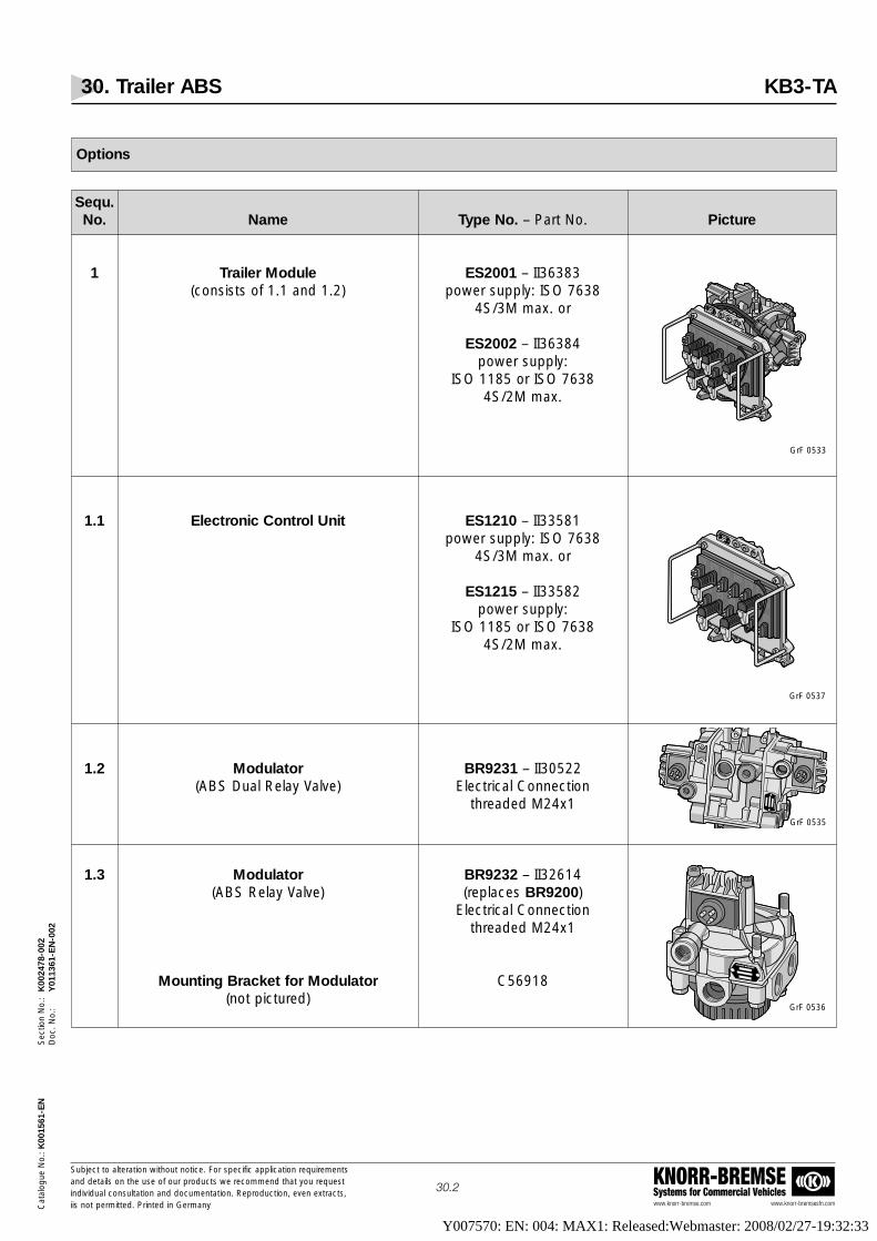
30. Trailer ABS KB3-TA
www.knorr-bremse.com www.knorr-bremsesfn.com
KNORR-BREMSESystems for Commercial Vehicles
Subject to alteration without notice. For specific application requirementsand details on the use of our products we recommend that you request individual consultation and documentation. Reproduction, even extracts,iis not permitted. Printed in Germany
30.2
Cat
alog
ue N
o.: K
0015
61-E
NS
ectio
n N
o.:
K00
2478
-002
Doc
. No.
:Y
0113
61-E
N-0
02
Sequ.No. Name Type No. – Part No. Picture
1 Trailer Module ES2001 – II36383(consists of 1.1 and 1.2) power supply: ISO 7638
4S/3M max. or
ES2002 – II36384 power supply:
ISO 1185 or ISO 76384S/2M max.
1.1 Electronic Control Unit ES1210 – II33581power supply: ISO 7638
4S/3M max. or
ES1215 – II33582power supply:
ISO 1185 or ISO 76384S/2M max.
1.2 Modulator BR9231 – II30522(ABS Dual Relay Valve) Electrical Connection
threaded M24x1
1.3 Modulator BR9232 – II32614(ABS Relay Valve) (replaces BR9200)
Electrical Connectionthreaded M24x1
Mounting Bracket for Modulator C56918(not pictured)
Options
GrF 0533
GrF 0537
GrF 0535
GrF 0536
Y007570: EN: 004: MAX1: Released:Webmaster: 2008/02/27-19:32:33

30. Trailer ABS KB3-TA
www.knorr-bremse.com www.knorr-bremsesfn.com
KNORR-BREMSESystems for Commercial Vehicles
Subject to alteration without notice. For specific application requirementsand details on the use of our products we recommend that you request individual consultation and documentation. Reproduction, even extracts,iis not permitted. Printed in Germany
30.3
Cat
alog
ue N
o.: K
0015
61-E
NS
ectio
n N
o.:
K00
2478
-002
Doc
. No.
:Y
0113
61-E
N-0
02
Sequ.No. Name Type No. – Part No. Picture
2 Modulator Cable EK3013 – II35417..available lengths: Electrical Connection
0,5 / 2 / 3 / 3,5 / 4 / 5 / 6 / 7 / 8 / threaded M24x110 / 12 and 15 m
3 Extension Cable for Wheel Speed Sensors EK3003 – II35416..available lengths:
2 / 3 / 3,5 / 4 / 5 / 6 / 7 / 8 / 9 /10 / 12 and 15 m
4 Power Supply EK3040 – II33587..Cable with open ends
(conforming to ISO 1185 for ECU ES1215or Trailer Module ES2002
orConnection Cable for "RET/VT"
for ECU ES1210or Tailer Module ES2001)
available lengths:3 / 4 / 5 / 8 and 12 m
5 Power Supply Cable EK3022 – II35415..with plug
(conforming to ISO 7638 for drawbar and centre axle trailers)available lengths:
6 / 8 / 9 / 10 / 12 / 15 and 23 m
6 Power Supply Cable EK3027 – II33588..(conforming to ISO 7638 with socket for
semi-trailers)available lengths:
8 / 9 / 10 / 12 / 13 and 15 m
7 Power Supply Cable EK3028 – II36417..(split version – part A)
with socket for semi-trailersavailable lengths:
8 / 9 / 10 / 12 and 14 m
8 Power Supply Cable EK3029 – II36418500(split version – part B)
length: 0,5 m
VF 00173/1
VF 00173/3
VF 00199/38
VF 00173/5
VF 00173/6
VF 00173/8
VF 00173/9
Options - continued -
Y007570: EN: 004: MAX1: Released:Webmaster: 2008/02/27-19:32:33

30. Trailer ABS KB3-TA
www.knorr-bremse.com www.knorr-bremsesfn.com
KNORR-BREMSESystems for Commercial Vehicles
Subject to alteration without notice. For specific application requirementsand details on the use of our products we recommend that you request individual consultation and documentation. Reproduction, even extracts,iis not permitted. Printed in Germany
30.4
Cat
alog
ue N
o.: K
0015
61-E
NS
ectio
n N
o.:
K00
2478
-002
Doc
. No.
:Y
0113
61-E
N-0
02
Sequ.No. Name Type No. – Part No. Picture
9 Dummy Socket I88007for drawbar and
centre axle trailers
Mounting Clamp for Dummy Socket B86617(not pictured)
10 Closing Cap II36744(only as spare part)
11 Closing Cap for Diagnostic Port II36386(only as spare part)
12 Wheel Speed Sensor see page 32.1
13 Sensor Bush II16774
14 Additional documentation:Installation manual C14404
System specification ES1210 C16225System specification ES1215 C16226
System description C14405Approval document EB 118.E,
FTP98/24952/A/03
KNORR-BREMSE KNORR-BREMSE
VF 00173/10
VF 00173/11
VF 00173/12
VF 00173/2
GrF 0323
Options - continued -
Y007570: EN: 004: MAX1: Released:Webmaster: 2008/02/27-19:32:33

Semi-trailer
2S/2M
4S/2M
4S/3M
30. Trailer ABS KB3-TA
www.knorr-bremse.com www.knorr-bremsesfn.com
KNORR-BREMSESystems for Commercial Vehicles
Subject to alteration without notice. For specific application requirementsand details on the use of our products we recommend that you request individual consultation and documentation. Reproduction, even extracts,iis not permitted. Printed in Germany
30.5
Cat
alog
ue N
o.: K
0015
61-E
NS
ectio
n N
o.:
K00
2478
-002
Doc
. No.
:Y
0113
61-E
N-0
02
Sequ.No. Name Type No. – Part No. Picture
1 Diagnostic Cable EK3050 – II35418..(suitable for assembly onto the chassis)available lengths: 1/ 3 / 4 / 5 and 8 m
2 Blink Code Switch EZ1022 – II36381(to connect to cable EK3050)
3 Adapter Cable EZ1020 – II354343000(to connect to a laptop or PC)
Length: 3 m
4 3,5" Disc II36390(diagnostic software for PC)
5 Diagnostic Set EZ1025 – II36391(consisting of Nos. 1 to 4)
Centre axle trailer
2S/2M
4S/2M
4S/3M
Drawbar trailer
4S/3M
System Variants
Components for Diagnostics
Y007570: EN: 004: MAX1: Released:Webmaster: 2008/02/27-19:32:33

30. Trailer ABS KB3-TA
www.knorr-bremse.com www.knorr-bremsesfn.com
KNORR-BREMSESystems for Commercial Vehicles
Subject to alteration without notice. For specific application requirementsand details on the use of our products we recommend that you request individual consultation and documentation. Reproduction, even extracts,iis not permitted. Printed in Germany
30.6
Cat
alog
ue N
o.: K
0015
61-E
NS
ectio
n N
o.:
K00
2478
-002
Doc
. No.
:Y
0113
61-E
N-0
02
Functions:Information is shown in three blocks of Coloured flashes of an LED on the ECU• Change / read System Configuration• Installation Test• Read / delete fault code memoryA full blink code list is provided.
EZ1022 EK3050
P-3448/4
Diagnostics
The ECU of the KB3-TA system is self-diagnosing. In the event of a fault, the towing vehicle´s "in-cab" or the trailer headboard warning light will illuminate and all components detected as defective are shut down either selectively or intotal. In the event of a total ABS shutdown all braking functions revert to standard operation.To ensure fast and effective trouble shooting, the ECU is provided with a universal diagnostic interface which allowsconnection to a hand held blink code switch or to a personal computer (PC) with extended functions.Once a fault has been rectified, the resetting of the ECU is achieved simply by removing and re-applying power to theunit. Faults are stored in the ECU memory and can be recalled and erased as required.
The ECU integrated test modules check the following components of the ABS system• connected components (Wheel Speed Sensors, Modulators)• complete wiring (Extension Cables and Connecting Cables to the Wheel Speed Sensors and Modulators, and Power
Supply Cables) and plug connections to the peripheral components.
Blink Code Diagnostics
Y007570: EN: 004: MAX1: Released:Webmaster: 2008/02/27-19:32:33

30. Trailer ABS KB3-TA
www.knorr-bremse.com www.knorr-bremsesfn.com
KNORR-BREMSESystems for Commercial Vehicles
Subject to alteration without notice. For specific application requirementsand details on the use of our products we recommend that you request individual consultation and documentation. Reproduction, even extracts,iis not permitted. Printed in Germany
30.7
Cat
alog
ue N
o.: K
0015
61-E
NS
ectio
n N
o.:
K00
2478
-002
Doc
. No.
:Y
0113
61-E
N-0
02
Functions:User friendly software• Change/read System Configuration• Installation Test• Read/delete fault code memory• Read further information: odometer, differential odometer, retarder control, velocity output
EK3050
EZ1020
Diagnostics - continued -
See diagnostic set EZ1025, function description
P-3448/5
PC Diagnostics
Y007570: EN: 004: MAX1: Released:Webmaster: 2008/02/27-19:32:33

31. ABS Relay Modulator Valves BR92..
www.knorr-bremse.com www.knorr-bremsesfn.com
KNORR-BREMSESystems for Commercial Vehicles
Subject to alteration without notice. For specific application requirementsand details on the use of our products we recommend that you request individual consultation and documentation. Reproduction, even extracts,iis not permitted. Printed in Germany
31.1
Cat
alog
ue N
o.: K
0015
61-E
NS
ectio
n N
o.:
K00
2479
-001
Doc
. No.
:Y
0113
62-E
N-0
01
Standard Symbol as DIN ISO 1219see page 31.4
GrF 0535
GrF 0536
Function
The Modulator with integrated Relay Valve is used on trailers with ABS to control the service brake pressure in one or more brake actuators.In a trailer air brake system, under non-ABS conditions, the Relay ModulatorValve acts as a standard Relay Valve and in response to an air pressure signal,speeds up brake applications by providing rapid and precise control of largevolumes of air.However, if during braking, the anti-lock braking system´s ECU detects that asensed wheel is decelerating too rapidly and wheel lock is imminent, it sendselectronic signals to the Relay Modulator Valve controlling that wheel. TheModulator Valve then rapidly modulates the braking pressure between thethree states of "release", "hold" and "apply". This continues until the risk ofwheel lock is overcome.The Relay Modulator Valve is available in both Single and Dual Relay form. TheDual Relay Modulator Valve can be used as an alternative to two single valvesfitted across the axle. The Dual Relay Valves use a single signal and a singlesupply port with the delivery ports independently controlled by their respectivemodulators.The Dual Relay Modulator Valve is used as a part of the Trailer ModuleAssemblies (ES200.).Please note that valves are supplied complete with Exhaust Silencers.
Technical details
Brake pressure max. 10 barRelay function YesMedium Compressed AirOperating Temperature Range -40 °C to +75 °CNominal voltage 24V DCWeight Single modulator: approximately 1,2 Kg
Dual modulator: approximately 2,9 kg
Options
Type No. Connections Mounting CommentBracket1)
BR9231 Electrical Connector - M24x1 (threaded) –Delivery Ports - 6x M22x1,5
BR9233 Electrical Connector - Bayonet Socket –Delivery Ports 6x M22x1,5
BR9232 Electrical Connector - M24x1 (threaded) Part No. Replacement forDelivery Ports - 4x M22x1,5 C56918 BR9200
1) Not supplied with the valves
Y007570: EN: 004: MAX1: Released:Webmaster: 2008/02/27-19:32:33

31. ABS Relay Modulator Valves BR92..
www.knorr-bremse.com www.knorr-bremsesfn.com
KNORR-BREMSESystems for Commercial Vehicles
Subject to alteration without notice. For specific application requirementsand details on the use of our products we recommend that you request individual consultation and documentation. Reproduction, even extracts,iis not permitted. Printed in Germany
31.2
Cat
alog
ue N
o.: K
0015
61-E
NS
ectio
n N
o.:
K00
2479
-001
Doc
. No.
:Y
0113
62-E
N-0
01
Dimensions
BR9231BR9233
Y007570: EN: 004: MAX1: Released:Webmaster: 2008/02/27-19:32:33

31. ABS Relay Modulator Valves BR92..
www.knorr-bremse.com www.knorr-bremsesfn.com
KNORR-BREMSESystems for Commercial Vehicles
Subject to alteration without notice. For specific application requirementsand details on the use of our products we recommend that you request individual consultation and documentation. Reproduction, even extracts,iis not permitted. Printed in Germany
31.3
Cat
alog
ue N
o.: K
0015
61-E
NS
ectio
n N
o.:
K00
2479
-001
Doc
. No.
:Y
0113
62-E
N-0
01
Dimensions - continued -
BR9232
Y007570: EN: 004: MAX1: Released:Webmaster: 2008/02/27-19:32:33

31. ABS Relay Modulator Valves BR92..
www.knorr-bremse.com www.knorr-bremsesfn.com
KNORR-BREMSESystems for Commercial Vehicles
Subject to alteration without notice. For specific application requirementsand details on the use of our products we recommend that you request individual consultation and documentation. Reproduction, even extracts,iis not permitted. Printed in Germany
31.4
Cat
alog
ue N
o.: K
0015
61-E
NS
ectio
n N
o.:
K00
2479
-001
Doc
. No.
:Y
0113
62-E
N-0
01
Symbol drawing, acc. to DIN ISO 1219
4.24.14.3
3
4
23
4.64.44.5
2323
222222
1 21
6.16.26.3
3
4
23
6.36.26.1
2323
222222
1 21
1
2
4.24.14.3
32
4
22
BR9231
BR9232
BR9233
Y007570: EN: 004: MAX1: Released:Webmaster: 2008/02/27-19:32:33

32. Wheel Speed Sensors 02650501.., 04860001..
www.knorr-bremse.com www.knorr-bremsesfn.com
KNORR-BREMSESystems for Commercial Vehicles
Subject to alteration without notice. For specific application requirementsand details on the use of our products we recommend that you request individual consultation and documentation. Reproduction, even extracts,iis not permitted. Printed in Germany
32.1
Cat
alog
ue N
o.: K
0015
61-E
NS
ectio
n N
o.:
K00
2480
-001
Doc
. No.
:Y
0113
63-E
N-0
01
Function
When fitted in conjunction with, but not in contact with, a Pole Wheel (ToothedSensing Ring), the Wheel Speed Sensor supplies the ECU of the trailer’s ABSwith precise wheel speed information.
The Wheel Speed Sensor is available in four cable lengths and is supplied witha standard two pin socket for connection to a Sensor Extension Cable.Please note, for installation, a Sensor Bush II16774 will be required.
The Wheel Speed Sensor is held in the mounting hole by the Sensor Bush.When fitting a new sensor always fit a new bush - Note: bush may not besupplied with sensor
Technical details
Operating Temperature Range:• Speed Sensor -40 °C to +160 °C• Cable -40 °C to +180 °C• Plug -40 °C to +80 °C
Options
R 3011 GrF 0299
Radial
Axial
Type No. L d Radial Axial PlugPart No. [mm] [mm]
Old types: replaced in 2nd quarter 2004
0265050104 400 5,4 X – With0265050108 2000 6,2 X – Without0265050131 1000 5,4 X – With0265050150 1000 5,4 X – 1)
0486001029 300 6,2 – X With
New types:
0486001032 350 4,4 – X With0486001033 1000 4,4 – X With0486000126 400 4,4 X – With0486000128 1000 4,4 X – With0486000130 2000 4,4 X – Without0486000136 1000 4,4 X – 1)
VF00199_173
1) With Sensor Bush
Y007570: EN: 004: MAX1: Released:Webmaster: 2008/02/27-19:32:33
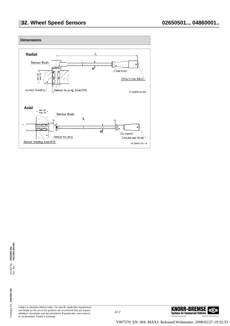
32. Wheel Speed Sensors 02650501.., 04860001..
www.knorr-bremse.com www.knorr-bremsesfn.com
KNORR-BREMSESystems for Commercial Vehicles
Subject to alteration without notice. For specific application requirementsand details on the use of our products we recommend that you request individual consultation and documentation. Reproduction, even extracts,iis not permitted. Printed in Germany
32.2
Cat
alog
ue N
o.: K
0015
61-E
NS
ectio
n N
o.:
K00
2480
-001
Doc
. No.
:Y
0113
63-E
N-0
01
Dimensions
Radial
Axial
Y007570: EN: 004: MAX1: Released:Webmaster: 2008/02/27-19:32:33

33. ABS Connection Cable (Coil) EK3150
www.knorr-bremse.com www.knorr-bremsesfn.com
KNORR-BREMSESystems for Commercial Vehicles
Subject to alteration without notice. For specific application requirementsand details on the use of our products we recommend that you request individual consultation and documentation. Reproduction, even extracts,iis not permitted. Printed in Germany
33.1
Cat
alog
ue N
o.: K
0015
61-E
NS
ectio
n N
o.:
K00
2481
-001
Doc
. No.
:Y
0113
64-E
N-0
01
GrF 0242
270
270
L
D
VF 00075/66
EK3150
Function
The ABS Connection Cable makes sure that the power supply is connected between Truck and Semi-trailer.
The Cable is to ISO 7638 standard and contains 7 cores making it suitable forABS and EBS.
Technical details
Operating Temperature Range: -40 ºC to +80 ºC
Options
Type No. Part No. Trailer type D [mm]
EK3150 K004098 Semi-trailer 55
Type No. L [mm] Comment
EK3150 Approx. 1.000 to 4.000 Approx. 25 coils
Dimensions
Y007570: EN: 004: MAX1: Released:Webmaster: 2008/02/27-19:32:33

34. ABS Trailer Module A18
www.knorr-bremse.com www.knorr-bremsesfn.com
KNORR-BREMSESystems for Commercial Vehicles
Subject to alteration without notice. For specific application requirementsand details on the use of our products we recommend that you request individual consultation and documentation. Reproduction, even extracts,iis not permitted. Printed in Germany
34.1
Cat
alog
ue N
o.: K
0015
61-E
NS
ectio
n N
o.:
K00
2482
-001
Doc
. No.
:Y
0113
65-E
N-0
01
Function
The Trailer Module is the assembly of an A18 Electronic Control Unit (ECU) and Dual Relay Modulator Valve. The A18 ECU isavailable as a 2S/2M configuration to suit semi-trailer and centre axle trailer applications. The ECU can be powered via ISO7638 only or a combination of ISO 7638 and ISO 1185 (24N).The 2S/2M version requires a Power Supply / Diagnostic Wiring Harness and a Modulator / Sensor Wiring Harness to complete the A18 Anti-Lock Braking System. Installation is simple compared to other systems since only two plugs have to beconnected to the ECU. The Modulator and Sensor Cables are colour coded to ensure ease of identification.For trailer management purposes the A18 ECU has Intelligent Operating Data Acquisition (IODA) which incorporates an odometer.The A18 ECU has a Velocity Output (VT) connection which can be used to signal an external device at a predetermined velocity. The A18 ECU provides a preset output signal at 15 km/h which can be adjusted in 5 km/h increments between 0 and 125km/h. It is also possible to program the hysteresis and the kind of signal (permanent or pulsed) via diagnostic software.The A18 ECU is self-diagnosing. In the event of a fault, the towing vehicle´s "in-cab" or the trailer headboard warning light will illuminate and all components detected as defective are shut down either selectively or in total. In the event of a total ABS shut down all braking functions revert to standard operation.
To ensure fast and effective trouble shooting, the ECU is provided with a universal diagnostic interface which, with DiagnosticSoftware (B 265 052 918), allows connection to a Personal Computer (PC) for fault diagnosis, odometer reading and velocityoutput parameter setting. Alternatively, a diagnostic Blink Code Switch (Type No. EZ1022) can be connected to the interfaceand, via its integral light, can be used to display the Diagnostic Blink Code. This can be achieved by depressing the switch fortwo seconds.
Once a fault has been rectified, the resetting of the ECU is simply achieved by removing and re-applying power to the unit. All faults are stored in the ECU memory and can be recalled and erased as required.When the system has been installed, manufacturers can perform an "end of line” test using a PC and the Diagnostic Software. The A18 ECU is available as a separate item or as a part of the Trailer Module Assembly ES2005.
Diagnosis is possible via a PC or Blink Code Switch. A trailer mounted warningdisplay can also be connected to the diagnostic port. This display is called a"Magic Eye" and switches automatically to red when a fault in the ECU is detected.
VF 00199_55
Standard Symbol as DIN ISO 1219
Technical details
Operating Pressure, max.: 10 barApproved Pressure, max.: 12,5 barOperating Temperature Range: -40 °C to +75 °CMedium: Compressed AirDegree of Protection: DIN 40050 part 9Nominal Voltage: 24V DCOperating Voltage: 19V to 30V DCApprox. Weight: 3,4 kgApprox. ECU Weight: 0,5 kgMax. Uni Output Signal: 1A
Y007570: EN: 004: MAX1: Released:Webmaster: 2008/02/27-19:32:33

34. ABS Trailer Module A18
www.knorr-bremse.com www.knorr-bremsesfn.com
KNORR-BREMSESystems for Commercial Vehicles
Subject to alteration without notice. For specific application requirementsand details on the use of our products we recommend that you request individual consultation and documentation. Reproduction, even extracts,iis not permitted. Printed in Germany
34.2
Cat
alog
ue N
o.: K
0015
61-E
NS
ectio
n N
o.:
K00
2482
-001
Doc
. No.
:Y
0113
65-E
N-0
01
Compact assembly unit:ECU and Dual Relay Modulator Valve
Options
Electronics
ABS Modulator
Compact Assembly Unit (Electronics + ABS Modulator)
Additional documentation:• Technical Documents for Customer: Y489M0063• Service Documents: 0486105002The compact unit is connected with the following cables:• Power Supply Cable acc. to ISO 7638• Cable loom with connector for ISO 7638, diagnostic cable and - as an option - connecting cable for Stop Light
powering acc. to ISO 1185• Cable loom with extention cable for the Wheel Speed Sensors and with connecting cable for the ABS Relay
Modulator ValvesThe description of the different cable variants can be found on the following pages.
Part No. Configuration Power supply
0486105002 2S/2M ISO 7638 & ISO 1185
Type No. Port threads Number of Tightening torquePart No. Ports
Supply:M22x1,5 2 60 Nm
acc. to DIN 3853BR9233II37090 Control:
M16x1,5 2 45 Nmacc. to DIN 3853
Delivery:M22x1,5 6 60 Nm
acc. to DIN 3853
Type No. – Part No. Configuration Power supply
ES2005 – II36413 2S/2M ISO 7638 & ISO 1185
Y007570: EN: 004: MAX1: Released:Webmaster: 2008/02/27-19:32:33

34. ABS Trailer Module A18
www.knorr-bremse.com www.knorr-bremsesfn.com
KNORR-BREMSESystems for Commercial Vehicles
Subject to alteration without notice. For specific application requirementsand details on the use of our products we recommend that you request individual consultation and documentation. Reproduction, even extracts,iis not permitted. Printed in Germany
34.3
Cat
alog
ue N
o.: K
0015
61-E
NS
ectio
n N
o.:
K00
2482
-001
Doc
. No.
:Y
0113
65-E
N-0
01
PIN configuration
Blink Code diagnostics
The Blink Code Switch can be connected to the diagnostic socket. The blink code output is visible at the Blink Code Switch (integrated LED) andat the warning light in the towing vehicle.
Magic Eye
A trailer mounted warning display, known as a "Magic Eye", can aslo beconnected to the diagnostic port. Under normal conditions, it has ablack display; as soon as a fault in the ECU is detected, the displayautomatically changes from black to red. This condition is held, even if thetrailer is uncoupled, as long as the fault is present. As a result of this, a parkedvehicle can be checked very quickly, even if no towing vehicle is available.After the fault has been rectified and the ECU has beenpowered, the Magic Eye display will switch back to a black displayautomatically.
PIN Signal Description
X1-1 DIA input/output level converter/ diagnosisX1-2 UDIA output supply level converter/ diagnosisX1-3 GND output earth level converter/ diagnosisX1-4 GND input earth control unitX1-5 WLEXT output external warning light for Stop Light supplyX1-6 UB input supply control unit batteryX1-7 GNDL input earth control unitX1-8 WL output warning lightX1-9 UZ input supply control unit ignitionX1-10 GND output earth Stop Light supplyX1-11 BVV/UBL input supply Stop Light supplyX1-12 BVS no configuration
PIN Signal Description
X2-1 EVA output inlet valve AX2-2 DFA- input speed sensor AX2-3 DFA+ input speed sensor AX2-4 DFB- input speed sensor BX2-5 DFB+ input speed sensor BX2-6 EVB output inlet valve BX2-7 GVR output earth valve BX2-8 AVB output outlet valve BX2-9 GND output earth universal outputX2-10 UNI output universal outputX2-11 AVA output outlet valve AX2-12 GVR output earth valve A
Y007570: EN: 004: MAX1: Released:Webmaster: 2008/02/27-19:32:33

Calling up the Blink Codes
To call up the blink codes, follow these instructions:• Switch on ignition• Connect Blink Code Switch to the external diagnostic plug• Depress the switch for at least two seconds• Release the switch• Count the number of blink pulses of the LED (two blocks of pulses).
The blink code is decoded from the two blocks:• The first block provides information about the actual system configuration• The second block provides information about the kind of malfunction
or the faulty component.
Block 1 Block 2Configuration Blink Pulses ABS fault Blink Pulses
ABS OK 1Speed sensor DFA 2) 2 1)
Speed sensor DFB 2) 3 1)
Solenoid valve MVA 2) 82S/2M 2 Solenoid valve MVB 2) 9
GVR, GNDL (earth) 11Power supply 12
Universal output 13Control unit internal 14
Delete fault code memory
After the fault has been eliminated, the fault code memory must be deleted.• Ignition off• Depress Blink Code Switch• Ignition on• Wait for at least two seconds• Release switch• LED flashes continuously ==> system OK• Check the blink code again
34. ABS Trailer Module A18
www.knorr-bremse.com www.knorr-bremsesfn.com
KNORR-BREMSESystems for Commercial Vehicles
Subject to alteration without notice. For specific application requirementsand details on the use of our products we recommend that you request individual consultation and documentation. Reproduction, even extracts,iis not permitted. Printed in Germany
34.4
Cat
alog
ue N
o.: K
0015
61-E
NS
ectio
n N
o.:
K00
2482
-001
Doc
. No.
:Y
0113
65-E
N-0
01
1) Having detected too big a gap between speed sensor and impulse ring, the last blink impulse will appear with doubled time (0,4 sec).2) An even number of blink pulses refers to a component (DFA/MVA) or cable on the left, an odd number of blink pulses refers to a component
(DFB/MVB) on the right side of the vehicle seen in forward driving direction.
Y007570: EN: 004: MAX1: Released:Webmaster: 2008/02/27-19:32:33

34. ABS Trailer Module A18
www.knorr-bremse.com www.knorr-bremsesfn.com
KNORR-BREMSESystems for Commercial Vehicles
Subject to alteration without notice. For specific application requirementsand details on the use of our products we recommend that you request individual consultation and documentation. Reproduction, even extracts,iis not permitted. Printed in Germany
34.5
Cat
alog
ue N
o.: K
0015
61-E
NS
ectio
n N
o.:
K00
2482
-001
Doc
. No.
:Y
0113
65-E
N-0
01
Test and Start Up
After complete system installation on the vehicle:• the correct allocation of the components connected to the ECU's plugs• the function of the pneumatic devicesmust be checked
Furthermore the ECU must be initialised:The ECU checks independently which components are connected to the wiring harness (configuration run). If the sensed configuration is different from the desired one or if a fault has been detected and memorised, the componentsmust be checked or changed and/or the wiring must be checked and corrected, as necessary. After this the faultmemory must be deleted. After a re-configuration (see below) the ECU must be re-initialised and the fault memory mustbe read. If the fault memory displays no further fault, the vehicle is permitted to move. If then the warning light continues to indicate no fault, the ABS is ready for operation.
ECU Reconfiguration
1. Ignition off2. Unplug wiring harness B (Wheel Speed Sensor and Modulator solenoid connections)3. Depress Blink Code Switch4. Ignition on5. Wait at least five seconds6. Ignition off7. Release switch8. Plug in wiring harness B9. Depress switch10. Ignition on11. Wait at least two seconds12. Release switch13. Read blink code (Block 1) and check new configuration
If there are no further faults in memory, the system puts out the blink code (Block 2) for "system OK”.
Please note that we advise for initial installationand End of Line checks to use Knorr-Bremse's
PC Diagnostics Program.
The ECU´s integrated blink code diagnostics cannot be used for this purpose because
it senses only electrical faults in external components anddoes not sense the correct allocation of the Wheel Speed Sensors and
Solenoid Valves to the corresponding wheels.
In principle this check is possible via ISO diagnosis.
Y007570: EN: 004: MAX1: Released:Webmaster: 2008/02/27-19:32:33

34. ABS Trailer Module A18
www.knorr-bremse.com www.knorr-bremsesfn.com
KNORR-BREMSESystems for Commercial Vehicles
Subject to alteration without notice. For specific application requirementsand details on the use of our products we recommend that you request individual consultation and documentation. Reproduction, even extracts,iis not permitted. Printed in Germany
34.6
Cat
alog
ue N
o.: K
0015
61-E
NS
ectio
n N
o.:
K00
2482
-001
Doc
. No.
:Y
0113
65-E
N-0
01
Wiring System, drawing
Y007570: EN: 004: MAX1: Released:Webmaster: 2008/02/27-19:32:33

34. ABS Trailer Module A18
www.knorr-bremse.com www.knorr-bremsesfn.com
KNORR-BREMSESystems for Commercial Vehicles
Subject to alteration without notice. For specific application requirementsand details on the use of our products we recommend that you request individual consultation and documentation. Reproduction, even extracts,iis not permitted. Printed in Germany
34.7
Cat
alog
ue N
o.: K
0015
61-E
NS
ectio
n N
o.:
K00
2482
-001
Doc
. No.
:Y
0113
65-E
N-0
01
Dimensions
Y007570: EN: 004: MAX1: Released:Webmaster: 2008/02/27-19:32:33
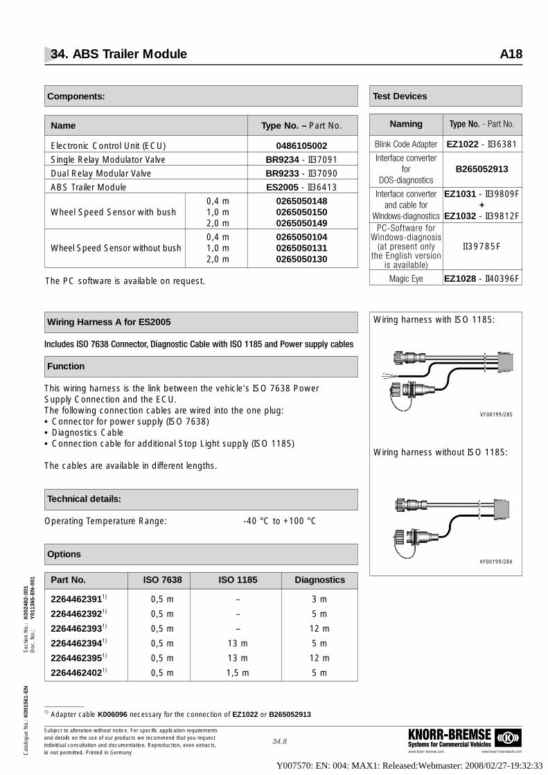
34. ABS Trailer Module A18
www.knorr-bremse.com www.knorr-bremsesfn.com
KNORR-BREMSESystems for Commercial Vehicles
Subject to alteration without notice. For specific application requirementsand details on the use of our products we recommend that you request individual consultation and documentation. Reproduction, even extracts,iis not permitted. Printed in Germany
34.8
Cat
alog
ue N
o.: K
0015
61-E
NS
ectio
n N
o.:
K00
2482
-001
Doc
. No.
:Y
0113
65-E
N-0
01
Test Devices
Naming Type No. - Part No.
Blink Code Adapter EZ1022 - II36381
Interface converterfor B265052913
DOS-diagnostics
Interface converter EZ1031 - II39809Fand cable for +
Windows-diagnostics EZ1032 - II39812FPC-Software for
Windows-diagnosisII39785F(at present only
the English version is available)
Magic Eye EZ1028 - II40396F
Components:
Name Type No. – Part No.
Electronic Control Unit (ECU) 0486105002
Single Relay Modulator Valve BR9234 - II37091
Dual Relay Modular Valve BR9233 - II37090
ABS Trailer Module ES2005 - II36413
0,4 m 0265050148Wheel Speed Sensor with bush 1,0 m 0265050150
2,0 m 0265050149
0,4 m 0265050104Wheel Speed Sensor without bush 1,0 m 0265050131
2,0 m 0265050130
The PC software is available on request.
Wiring Harness A for ES2005
Includes ISO 7638 Connector, Diagnostic Cable with ISO 1185 and Power supply cables
Function
This wiring harness is the link between the vehicle's ISO 7638 PowerSupply Connection and the ECU. The following connection cables are wired into the one plug:• Connector for power supply (ISO 7638)• Diagnostics Cable• Connection cable for additional Stop Light suppIy (ISO 1185)
The cables are available in different lengths.
Technical details:
Operating Temperature Range: -40 °C to +100 °C
Options
Part No. ISO 7638 ISO 1185 Diagnostics
22644623911) 0,5 m – 3 m
22644623921) 0,5 m – 5 m
22644623931) 0,5 m – 12 m
22644623941) 0,5 m 13 m 5 m
22644623951) 0,5 m 13 m 12 m
22644624021) 0,5 m 1,5 m 5 m
Wiring harness with ISO 1185:
Wiring harness without ISO 1185:
VF00199/285
VF00199/284
1) Adapter cable K006096 necessary for the connection of EZ1022 or B265052913
Y007570: EN: 004: MAX1: Released:Webmaster: 2008/02/27-19:32:33

34. ABS Trailer Module A18
www.knorr-bremse.com www.knorr-bremsesfn.com
KNORR-BREMSESystems for Commercial Vehicles
Subject to alteration without notice. For specific application requirementsand details on the use of our products we recommend that you request individual consultation and documentation. Reproduction, even extracts,iis not permitted. Printed in Germany
34.9
Cat
alog
ue N
o.: K
0015
61-E
NS
ectio
n N
o.:
K00
2482
-001
Doc
. No.
:Y
0113
65-E
N-0
01
Cable with socket
Cable with plug
Power Supply Cable according to DIN ISO 7638:
Function
The Power supply cable with ISO 7638 plug or socket is designatedfor the supply to the ABS Module ES2005. It is connected with a bayonetconnector to the wiring harness A.The cable is available in different lengths.
Technical details:
Operating Temperature Range: -40 °C to +80 °C
Options:
Power Supply cables with socket (for semi-trailers)
Power supply cable with plug (for drawbar trailers and center axle trailers)
Part No. Lengths
2264462396 8,0 m
2264462397 12,0 m
2264462398 14,0 mm
Part No. Lengths
2264462399 8,0 m
2264462400 10,0 m
VF 00199_150
VF 00199_151
Y007570: EN: 004: MAX1: Released:Webmaster: 2008/02/27-19:32:33

34. ABS Trailer Module A18
www.knorr-bremse.com www.knorr-bremsesfn.com
KNORR-BREMSESystems for Commercial Vehicles
Subject to alteration without notice. For specific application requirementsand details on the use of our products we recommend that you request individual consultation and documentation. Reproduction, even extracts,iis not permitted. Printed in Germany
34.10
Cat
alog
ue N
o.: K
0015
61-E
NS
ectio
n N
o.:
K00
2482
-001
Doc
. No.
:Y
0113
65-E
N-0
01
Wiring harness A, without power supply acc. to ISO 1185 (Stop Light)
Wiring harness A, with power supply acc. to ISO 1185 (Stop Light)
Dimensions
Y007570: EN: 004: MAX1: Released:Webmaster: 2008/02/27-19:32:33

34. ABS Trailer Module A18
www.knorr-bremse.com www.knorr-bremsesfn.com
KNORR-BREMSESystems for Commercial Vehicles
Subject to alteration without notice. For specific application requirementsand details on the use of our products we recommend that you request individual consultation and documentation. Reproduction, even extracts,iis not permitted. Printed in Germany
34.11
Cat
alog
ue N
o.: K
0015
61-E
NS
ectio
n N
o.:
K00
2482
-001
Doc
. No.
:Y
0113
65-E
N-0
01
Dimensions
Power supply cable for semi-trailers
Power supply cable for drawbar trailers and centre axle trailers
Y007570: EN: 004: MAX1: Released:Webmaster: 2008/02/27-19:32:33

34. ABS Trailer Module A18
www.knorr-bremse.com www.knorr-bremsesfn.com
KNORR-BREMSESystems for Commercial Vehicles
Subject to alteration without notice. For specific application requirementsand details on the use of our products we recommend that you request individual consultation and documentation. Reproduction, even extracts,iis not permitted. Printed in Germany
34.12
Cat
alog
ue N
o.: K
0015
61-E
NS
ectio
n N
o.:
K00
2482
-001
Doc
. No.
:Y
0113
65-E
N-0
01
Wiring harness BPart No. Modulator Speed Sensor UNI output Weight
2264462373 0,5 m 3,0 m - 0,6 kg
2264462374 0,5 m 4,0 m - 0,8 kg
2264462375 0,5 m 6,5 m - 1,0 kg
2264462376 1,5 m 3,0 m - 0,8 kg
2264462377 1,5 m 4,0 m - 1,0 kg
2264462378 1,5 m 6,5 m - 1,2 kg
2264462379 3,0 m 3,0 m - 1,1 kg
2264462380 3,0 m 4,0 m - 1,3 kg
2264462381 3,0 m 6,5 m - 1,5 kg
2264462382 6,0 m 3,0 m - 1,4 kg
2264462383 6,0 m 4,0 m - 1,6 kg
2264462384 6,0 m 6,5 m - 1,8 kg
2264462403 0,5 m 3,0 m 6,5 m 1,6 kg
Wiring Harness B for A18 with Wheel Speed Sensor extension cable, Modulator Relay Valve cable and cable for UNI output
Function
Wiring Harness B connects the following cables to a plug for connection to the ECU:• Connecting cables for the ABS Relay Valves• Wheel Speed Sensor extension cables• As an option: connecting cable for the speed sensing signal (UNI output).
The cables are available in different lengths.
Colour Coding of the Modulator and Wheel Speed Sensor Cables ensure easeof installation. It is recommended that blue coded cables are used on the lefthand side (seen in forward driving direction) and yellow coded cables on theright hand side of the trailer.
Technical details:
Operating Temperature Range: -40 °C to +100 °CApprox. Weight: See table
Options
VF 00199_152
Y007570: EN: 004: MAX1: Released:Webmaster: 2008/02/27-19:32:33

34. ABS Trailer Module A18
www.knorr-bremse.com www.knorr-bremsesfn.com
KNORR-BREMSESystems for Commercial Vehicles
Subject to alteration without notice. For specific application requirementsand details on the use of our products we recommend that you request individual consultation and documentation. Reproduction, even extracts,iis not permitted. Printed in Germany
34.13
Cat
alog
ue N
o.: K
0015
61-E
NS
ectio
n N
o.:
K00
2482
-001
Doc
. No.
:Y
0113
65-E
N-0
01
Dimensions
Y007570: EN: 004: MAX1: Released:Webmaster: 2008/02/27-19:32:33

34. ABS Trailer Module KB3-TA
www.knorr-bremse.com www.knorr-bremsesfn.com
KNORR-BREMSESystems for Commercial Vehicles
Subject to alteration without notice. For specific application requirementsand details on the use of our products we recommend that you request individual consultation and documentation. Reproduction, even extracts,iis not permitted. Printed in Germany
34.14
Cat
alog
ue N
o.: K
0015
61-E
NS
ectio
n N
o.:
K00
2482
-001
Doc
. No.
:Y
0113
65-E
N-0
01
VF 00199_283
Diagnostics Adapter Cable
Function
If Blink Code Switch EZ1022 or the interface converter for DOS-diagnosticsB265052913 should be connected, this adapter cable is required.
Options
Dimensions
Type No. Part No. Cable length "L" [m]
K0060961) 0,5
1) Cable not deliverable before quarter 3/2004
Y007570: EN: 004: MAX1: Released:Webmaster: 2008/02/27-19:32:33

34. ABS Trailer Module
www.knorr-bremse.com www.knorr-bremsesfn.com
KNORR-BREMSESystems for Commercial Vehicles
Subject to alteration without notice. For specific application requirementsand details on the use of our products we recommend that you request individual consultation and documentation. Reproduction, even extracts,iis not permitted. Printed in Germany
34.15
Cat
alog
ue N
o.: K
0015
61-E
NS
ectio
n N
o.:
K00
2482
-001
Doc
. No.
:Y
0113
65-E
N-0
01
Test Report
Y007570: EN: 004: MAX1: Released:Webmaster: 2008/02/27-19:32:33

Cata
logue N
o.: K
0015
61S
ection N
o.:
K00
2483
-000
Doc.
No.:
Y01
1366
-EN
-000
Subject to alteration without notice. For specific application requirements
and details on the use of our products we recommend that you request
individual consultation and documentation. Reproduction, even extracts,
is not permitted. Printed in Germany
40.1
40. Electronic Braking System for Trailers TEBS
Function
The electronic braking system for trailers (TEBS) combines, in one compact
assembly, the electronic control unit, the sensor technology and the pneumatic
control.
The braking functions of anti-lock and load sensing control are both electronically
managed within the module as integrated features. This provides more accurate
and consistent control of the generated braking force including reduced
hysteresis compared to a conventional braking system, thereby improving
tractor-trailer compatibility, optimising the brake pad wear and helping to reduce
the overall operating costs of the trailer.
The anti-compounding function is also housed within the module.
As an additional option, the function Roll Stability Program (RSP) is available.
Should a driver underestimate the vehicle speed when carrying out a manoeuvre,
particularly when the trailer is laden with a high centre of gravity, there is a real
danger that the trailer will become unstable and roll over. Even if the driver
becomes aware of the condition of the trailer, it is normally too late to prevent an
accident.
The RSP function of TEBS helps to avoid this by automatically applying the
brakes of selected trailer wheels. By monitoring lateral acceleration, load and
speed, the system is able to determine when an unstable condition is imminent.
Should this condition arise, the brakes are automatically applied to reduce
vehicle speed and hence lateral acceleration, thereby enhancing vehicle stability.
When the threat of instability is no longer present, the brakes are automatically
released and the system reverts to normal operation. RSP is available as an
option within TEBS and can be realised without any additional components
having to be installed on the trailer. Operation of the TEBS and RSP function is
independent of the specifications of the tractor.
RSP is available for semi, centre axle, and drawbar trailers.
The following Auxiliary Functions may be configured to the associated Auxiliary
connections of the TEBS:
1. Standard Auxiliary Functions:
1.1 Outputs• Fully Automatic Life Axle Control: The ECU provides an electrical signal for
the Knorr-Bremse lift axle control valve AE114. and ensures that the legal
requirements are fulfilled by preventing overloading of the axles.
The TEBS electronics can control up to two lift axle control valves, each valve
may then be connected to 1 or 2 lifting axles.
• RtR (Reset to Ride): In conventional suspension control systems, the Raise / Lower valve is often not reset to the
drive position before the vehicle is moved and damage can be caused to the suspension and brakes. To prevent this
happening, the TEBS ECU can be programmed to supply an electrical signal to a Raise / Lower Valve with suitable
functionality such that when the vehicle exceeds a pre-determined threshold speed, this signal causes the Raise /
Lower valve to automatically switch to the drive position.
• ISS (Integreated Speed Switch): The TEBS provides an electrical output signal when a pre-programmed vehicle
speed has been reached.
This signal may be used to fulfil numerous operational requirements such as locking of steering axles etc.
The signal can be programmed to switch from 0V to 24V or 24V to 0V.
The hysteresis, i.e. the difference between switch on and switch off speeds, can be adjusted in four steps between
10% and 80%.
VF00199_176
Standard Symbol as DIN ISO 1219
only for BR9234
3 TEBS
UP
UP
UP
UP
UP
3
22
22
2222
21
2121
24
23
1-2
42
1.24 1.1
1
2
6.16.26.3
32
4
BR 9234
M1M2
22
Y007570: EN: 004: MAX1: Released:Webmaster: 2008/02/27-19:32:33

40. Electronic Braking System for Trailers TEBS
www.knorr-bremse.com www.knorr-bremsesfn.com
KNORR-BREMSESystems for Commercial Vehicles
Subject to alteration without notice. For specific application requirementsand details on the use of our products we recommend that you request individual consultation and documentation. Reproduction, even extracts,is not permitted. Printed in Germany
40.2
Cat
alog
ue N
o.: K
0015
61-E
NS
ectio
n N
o.:
K00
2483
-002
Doc
. No.
:Y
0113
66-E
N-0
02
• 24 V Supply: Provides a permanent power supply that may be used to power additional brake and running gear systems / functions on the trailer.
• ABS active: When the ABS of the trailer is active, a 24V signal is transmitted by the ECU. Typically this function may be used to switch off a retarder installed on the trailer while ABS is active.
• RSP active: When the RSP of the trailer is active, a 24V signal is transmitted by the ECU.• TOC (Trailer Occurrence Counter): Every kilometre travelled, the ECU transmits a 24V signal for a period of time
and this may be used to trigger an external mileage counter.
1.2 Inputs:The TEBS ECU has the ability to evaluate and / or react to three sensor inputs as follows:• Brake Pad Wear control: When an input is received that the wear limit of at least one brake has been reached, the
information can be accessed via PC Diagnostics, Magic Eye or TIM. In addition, an electrical signal will be transmittedto the towing vehicle via pin 5 of the ISO 7638 connector causing the yellow warning lamp to flash each time the system is initially powered and the vehicle is stationary. A CAN signal is also transmitted via pins 6 and 7 of the ISO 7638 which may be used in the driver's information display (if the towing vehicle has such a device).
• Traction Assist: Raises the front lift axle when the trailer is laden to increase the imposed load on the towing vehicle. Axle overload and speed restrictions apply when this function in operational.
• Disable Lift Axle Control: signals the lift axle(s) to lower in the unladen case; this is activated by a signal transmitted by the towing vehicle or by an electrical switch mounted on the trailer.
2. Non-Standard Auxiliary Functions (via ADL):
Should a customer require a function, other than those normally available, it is possible to create a non-standardfunction by the use of a special program file known as Auxiliary Design Language (ADL) produced by Knorr-Bremse.Should such a function be required, contact must be made through the local Knorr-Bremse representative. When avai-lable, the special file needed to fulfil the function can be written to the ECU via the PC Diagnostic Program.
3. Stop Light powering:
To obtain full functionality, any trailer electronic braking system requires a permanent power supply (achieved by usingthe legally specified ISO7638 connection in 5 or 7 pin format); this ensures load sensing, anti-lock control and all auxiliary functions are automatically maintained. In the event of a failure of this power supply, whilst trailer braking will bemaintained via the pneumatic back-up function, all electronically controlled functionality would no longer be active.Continued operation of the vehicle without electrical power, irrespective of axle load, may therefore result in higherbrake operating temperatures leading to increased brake pad wear, tyre flat spotting and trailer instability. To overcomethis problem, the TEBS ECU can be installed so that it will continue to operate by taking power from the Stop Light circuit and thereby load sensing and anti-lock functions remain active.
Note:Stop Light powering should only be considered as a back-up function to ensure some safety features are retained.Operation of the vehicle over a longer period without a fully functioning ISO 7638 conector is not legal.
Function - continued -
Y007570: EN: 004: MAX1: Released:Webmaster: 2008/02/27-19:32:33

Cat
alog
ue N
o.: K
0015
61-E
NS
ectio
n N
o.:
K00
2483
-002
Doc
. No.
:Y
0113
66-E
N-0
02
40. Electronic Braking System for Trailers TEBS
www.knorr-bremse.com www.knorr-bremsesfn.com
KNORR-BREMSESystems for Commercial Vehicles
Subject to alteration without notice. For specific application requirementsand details on the use of our products we recommend that you request individual consultation and documentation. Reproduction, even extracts,is not permitted. Printed in Germany
40.3
Technical Features
Operating pressure: 10,0 barMax. permissable pressure: 12,5 barOperating temperature range: -40 °C to +65 °CMedium: Compressed airApprox. weight: 5,7 kg (BR9234: 1,2 kg)Nominal voltage: 24 V DC
Requirements for Towing Vehicle
Trailers fitted with an Electronic Braking System (TEBS) only comply with thelegal requirements of Regulations 98/12/EC and ECE Regulation 13/09Supplement 08, when the towing vehicle is equipped with an electrical interface of the following specification:ISO 7638: 1985 5 PinISO 7638: 1997 Part 1 (24V) 5 PinISO 7638: 1997 Part 1 (24V) 7 Pin
Options
Type No. Part No. Possible Auxiliary Functions RSPABS X1 connector1) X2 connector
Configu- Total Auxiliaries: 2ration Max. Max. Max. Max.
Out In Out In
ES20414) II39783F3) 2S/2M 2 12) 0 0 No
ES2050 II397983) 2S-4S/2M 1 12) 3 2 No
2S-4S/2M 1 12) 3 2 NoES2050 II397984S3M
4S/3M 1 12) 15) 2 No
2S-4S/2M 1 12) 3 2 YesES2053 II397823)
4S/3M 1 12) 15) 2 Yes
1) Only possible if TIM or Magic Eye are not used; maximumnumber of configurable Auxiliaries on X1 connector: 2
2) No “Traction Help”, no “Disable Lift Axle Control” 3) The suffix F004 can optionally be added to each Part Number, except for ES2041. There, attach only 004.
The Module will then be supplied in a single package with a system plate and an information sticker “EBS power supply” 4) Replaces ES2050 - II364195) Two of the X2 Auxiliary Outputs are required to power the external ABS Modulator Valve (BR9234) in the 4S/3M system
Type No. for Repair KitCover: II36750
Y007570: EN: 004: MAX1: Released:Webmaster: 2008/02/27-19:32:33

Cat
alog
ue N
o.: K
0015
61-E
NS
ectio
n N
o.:
K00
2483
-002
Doc
. No.
:Y
0113
66-E
N-0
02
www.knorr-bremse.com www.knorr-bremsesfn.com
KNORR-BREMSESystems for Commercial Vehicles
Subject to alteration without notice. For specific application requirementsand details on the use of our products we recommend that you request individual consultation and documentation. Reproduction, even extracts,is not permitted. Printed in Germany
40.4
Information sticker, TEBS power supplyPart No.: II39796FSize [mm]: 150 x 100
EBS-System Plate2):Part No.: II39797FSize [mm]: 170 x 110
40. Electronic Braking System for Trailers TEBS
1) If only one supply port is required, 1.1 must be used and 1.2 must be plugget.2) The System Plate is a sticker which can be printed via the ECU Talk software and a laser printer.
Caution! A laser printer must be used but do not print more than 5 stickers at a time.
P n e u m a t i c P o r t s :port number use for M22x1,5 M16x1,5
1.11) 1 Supply to Reservoir X
1.21) 1 Supply X
1-2 1 To AE43.. Park / Shunt Valve X
21 3 Delivery to brake chambers, right X
22 3 Delivery to brake chambers, left X
22 1 Test connector X
23 1 Delivery to parking brake X
24 1 Delivery to parking brake X
4 1 Brake demand (Yellow Line) X
42 1 Air spring pressure X VF00075/188
VF00075/189
EBSALB (LSV/CDF)
ABSII39796F
Trailer EBS KNORR-BREMSESysteme für Nutzfahrzeuge
Option - continued -
Y007570: EN: 004: MAX1: Released:Webmaster: 2008/02/27-19:32:33

Cat
alog
ue N
o.: K
0015
61-E
NS
ectio
n N
o.:
K00
2483
-002
Doc
. No.
:Y
0113
66-E
N-0
02
www.knorr-bremse.com www.knorr-bremsesfn.com
KNORR-BREMSESystems for Commercial Vehicles
Subject to alteration without notice. For specific application requirementsand details on the use of our products we recommend that you request individual consultation and documentation. Reproduction, even extracts,is not permitted. Printed in Germany
40.5
40. Electronic Braking System for Trailers TEBS
Dimensions
ES2041ES2050ES2053
Electrical connections
1) Only available for ES2041
X1 - connector
Pin Diagnose via K-Line or Diagnose via CANTIM or Magic Eye
AUX 5 (24V)1) or1 Diagnostics
Input C - signal
2 Diagnostics - ground ground
3 ISO 11992 CAN low (ISO7638: 1,5 mm2 WH / BN)
4 Modulator – ground (ISO7638: 4,0 mm2 BN)
5 ISO 11992 CAN high (ISO7638: 1,5 mm2 WH / GN)
6 Modulator – 24 V (ISO7638: 4,0 mm2 RD)
7 ECU – ground (ISO7638: 1,5 mm2 YE)
8 Warning Lamp (ISO7638: 1,5 mm2 WH)
9 ECU - 24 V (ISO7638: 1,5 mm2 BK)
10 Diagnostics - 24 V AUX 4 (24V)
11 Stop Light - ground (ISO1185: 1,0 mm2 BK)
12 Stop Light - 24 V (ISO1185: 1,0 mm2 YE)
X2 - connector
Pin 2S / 2M 4S / 3M4S / 2M
External ABS Modulator (BR9234) - Hold Valve1 AUX 1 (24V)
(1,0 mm2 YE)
External ABS Modulator (BR9234) - Release Valve2 AUX 2 (24V)
(1,0 mm2 BK)
3 AUX 3 (24V)
4 Input supply (5V)
5 Input A - signal
6 Input A - ground
7 Input B - ground
8 Input B - signal
9 –
10 –
11 Ground
External ABS Modulator (BR9234) - Ground12 Ground
(1,0 mm2 WH)
Y007570: EN: 004: MAX1: Released:Webmaster: 2008/02/27-19:32:33

40. Electronic Braking System for Trailers TEBS
www.knorr-bremse.com www.knorr-bremsesfn.com
KNORR-BREMSESystems for Commercial Vehicles
Subject to alteration without notice. For specific application requirementsand details on the use of our products we recommend that you request individual consultation and documentation. Reproduction, even extracts,is not permitted. Printed in Germany
40.6
Cat
alog
ue N
o.: K
0015
61-E
NS
ectio
n N
o.:
K00
2483
-002
Doc
. No.
:Y
0113
66-E
N-0
02
Dimensions
BR9234
Y007570: EN: 004: MAX1: Released:Webmaster: 2008/02/27-19:32:33

Cat
alog
ue N
o.: K
0015
61-E
NS
ectio
n N
o.:
K00
2483
-002
Doc
. No.
:Y
0113
66-E
N-0
02
www.knorr-bremse.com www.knorr-bremsesfn.com
KNORR-BREMSESystems for Commercial Vehicles
Subject to alteration without notice. For specific application requirementsand details on the use of our products we recommend that you request individual consultation and documentation. Reproduction, even extracts,is not permitted. Printed in Germany
40.7
40. Electronic Braking System for Trailers TEBS
Legal Requirements
TEBS has been approved in accordance with the requirements of Annex XIV of the Directive 98/12/EC and Annex 19 ofECE Regulation 13 with respect to ABS performance (see approval report EB 130 and the information documentC16427/E). The system also fulfils the requirements of the ECE regulation 13/09 Supplement 8 with respect to the prescribed requirements for vehicles with an electric control line and electric control transmission. (See approval report No. EB 133 and the information document C16428/E).
Additional Documents
Documentation is available which gives detailed information about the Electronic Braking System such asa system description and detailed installation instructions. Please ask your Knorr-Bremse technical sales representativefor these documents or send an order with the respective part numbers:
Information document C16427
Installation manual TEBS, German Y002324, DE
Installation manual TEBS, English Y002324, EN
Product information TEBS P-3528 German, English, French, Italian, Hungarian
User's manual for PC Diagnostics Available as a PDF File on the CD-ROM - II39785FECU Talk
TEBS - Wiring Harnesses
The following cables are needed for the use of TEBS:• Power Supply Cable• Cable for the X1 connector• Cable for the X2 connector (for auxiliary functions or 4S/3M axle modulator)• Two or four sensor extension cables (depending on the ABS configuration)
Technical Features
Operating temperature range: -40 °C to +80 °
1. Wiring Harness, pre-assembled1.1 Power Supply Cable
Function
Power Supply Cables, with plug or socket according to ISO 7638 + CAN, must only be used for the power supply ofthe braking equipment of the trailer.
The cables are available in various lengths and are supplied with a bayonet connector to ensure easy and safe connection.
Y007570: EN: 004: MAX1: Released:Webmaster: 2008/02/27-19:32:33
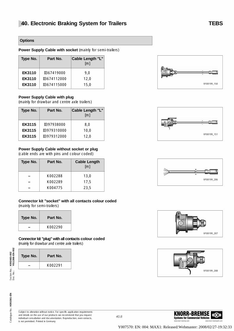
Cat
alog
ue N
o.: K
0015
61-E
NS
ectio
n N
o.:
K00
2483
-002
Doc
. No.
:Y
0113
66-E
N-0
02
www.knorr-bremse.com www.knorr-bremsesfn.com
KNORR-BREMSESystems for Commercial Vehicles
Subject to alteration without notice. For specific application requirementsand details on the use of our products we recommend that you request individual consultation and documentation. Reproduction, even extracts,is not permitted. Printed in Germany
40.8
40. Electronic Braking System for Trailers TEBS
Type No. Part No. Cable Length "L"[m]
EK3110 II367419000 9,0
EK3110 II3674112000 12,0
EK3110 II3674115000 15,0 VF00199_150
Type No. Part No. Cable Length "L" [m]
EK3115 II397938000 8,0
EK3115 II3979310000 10,0
EK3115 II3979312000 12,0VF00199_151
Options
Power Supply Cable with socket (mainly for semi-trailers)
Power Supply Cable with plug (mainly for drawbar and centre axle trailers)
Power Supply Cable without socket or plug(cable ends are with pins and colour coded)
Connector kit "socket" with all contacts colour coded(mainly for semi-trailers)
Connector kit "plug" with all contacts colour coded(mainly for drawbar and centre axle trailers)
Type No. Part No. Cable Length[m]
– K002288 13,0
– K002289 17,5
– K004775 23,5
Type No. Part No.
– K002290
Type No. Part No.
– K002291
VF00199_206
VF00199_207
VF00199_208
Y007570: EN: 004: MAX1: Released:Webmaster: 2008/02/27-19:32:33

40. Electronic Braking System for Trailers TEBS
www.knorr-bremse.com www.knorr-bremsesfn.com
KNORR-BREMSESystems for Commercial Vehicles
Subject to alteration without notice. For specific application requirementsand details on the use of our products we recommend that you request individual consultation and documentation. Reproduction, even extracts,is not permitted. Printed in Germany
40.9
Cat
alog
ue N
o.: K
0015
61-E
NS
ectio
n N
o.:
K00
2483
-002
Doc
. No.
:Y
0113
66-E
N-0
02
EK3110
EK3115
Dimensions
K002288K002289K004775
K002290
K002291
Pin Cable colour 1) Cross section Function[mm2]
Power1 Red 4,0 Solenoid
Valves
2 Black 1,5 Power ECU
3 Yellow 1,5 Ground ECU
Ground4 Brown 4,0 Solenoid
Valves
5 White 1,5 Warning Lamp
6 White / Green 1,5 CAN High
7 White / Brown 1,5 CAN Low
1) Only for original K-B systems
Y007570: EN: 004: MAX1: Released:Webmaster: 2008/02/27-19:32:33
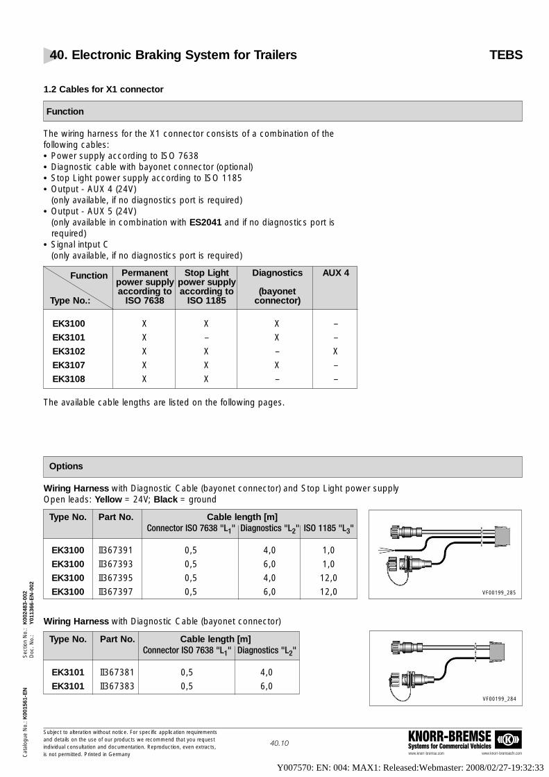
Type No. Part No. Cable length [m]Connector ISO 7638 "L1" Diagnostics "L2" ISO 1185 "L3"
EK3100 II367391 0,5 4,0 1,0
EK3100 II367393 0,5 6,0 1,0
EK3100 II367395 0,5 4,0 12,0
EK3100 II367397 0,5 6,0 12,0
Type No. Part No. Cable length [m]Connector ISO 7638 "L1" Diagnostics "L2"
EK3101 II367381 0,5 4,0
EK3101 II367383 0,5 6,0
VF00199_285
VF00199_284
Cat
alog
ue N
o.: K
0015
61-E
NS
ectio
n N
o.:
K00
2483
-002
Doc
. No.
:Y
0113
66-E
N-0
02
www.knorr-bremse.com www.knorr-bremsesfn.com
KNORR-BREMSESystems for Commercial Vehicles
Subject to alteration without notice. For specific application requirementsand details on the use of our products we recommend that you request individual consultation and documentation. Reproduction, even extracts,is not permitted. Printed in Germany
40.10
40. Electronic Braking System for Trailers TEBS
1.2 Cables for X1 connector
Function
The wiring harness for the X1 connector consists of a combination of thefollowing cables:• Power supply according to ISO 7638• Diagnostic cable with bayonet connector (optional)• Stop Light power supply according to ISO 1185• Output - AUX 4 (24V)
(only available, if no diagnostics port is required)• Output - AUX 5 (24V)
(only available in combination with ES2041 and if no diagnostics port isrequired)
• Signal intput C(only available, if no diagnostics port is required)
The available cable lengths are listed on the following pages.
Options
Wiring Harness with Diagnostic Cable (bayonet connector) and Stop Light power supplyOpen leads: Yellow = 24V; Black = ground
Wiring Harness with Diagnostic Cable (bayonet connector)
Function Permanent Stop Light Diagnostics AUX 4power supply power supplyaccording to according to (bayonet
Type No.: ISO 7638 ISO 1185 connector)
EK3100 X X X –
EK3101 X – X –
EK3102 X X – X
EK3107 X X X –
EK3108 X X – –
Y007570: EN: 004: MAX1: Released:Webmaster: 2008/02/27-19:32:33

40. Electronic Braking System for Trailers TEBS
www.knorr-bremse.com www.knorr-bremsesfn.com
KNORR-BREMSESystems for Commercial Vehicles
Subject to alteration without notice. For specific application requirementsand details on the use of our products we recommend that you request individual consultation and documentation. Reproduction, even extracts,is not permitted. Printed in Germany
40.11
Cat
alog
ue N
o.: K
0015
61-E
NS
ectio
n N
o.:
K00
2483
-002
Doc
. No.
:Y
0113
66-E
N-0
02
Type No. Part No. Cable Length [m]Connector ISO 7638 "L1" ISO 1185 "L2" Aux-4 "L3"
EK3102 K002945 0,5 1,0 2,0
EK3102 K002946 0,5 6,0 2,0
EK3102 K002947 0,5 12,0 2,0
EK3102 K002948 0,5 1,0 6,0
EK3102 K002949 0,5 6,0 6,0
EK3102 K002950 0,5 12,0 6,0
EK3102 K004754 0,5 1,0 4,0
EK3102 K004755 0,5 6,0 4,0
EK3102 K004756 0,5 12,0 4,0
EK31021) K005684 0,5 6,0 6,0
EK31022) K007524 0,5 1,0 4,0
1) Output Aux 4 with elbow DIN bayonet connector2) Connection ISO 1185 with DIN bayonet pin connector3) A mounting kit (Part No: K005378, consisting of a closure cap, a spring ring and a nut) may be used
Type No. Part No. Cable Length [m]Connector ISO 7638 "L1" ISO 1185 "L2"
EK3108 II40391F1 0,5 1,0
EK3108 II40391F2 0,5 12,0 VF00199_199
VF00199_295
VF00199_210
VF00199_286
Type No. Part No. Cable Length [m]Connector ISO 7638 "L1"
– K002286 0,5 VF00199_258
Type No. Part No. Cable Length [m]Connector ISO 7638 "L1" Diagnostic "L2" ISO 1185 "L3"
EK31072); 3) K007525 0,5 4,0 1,0
VF00199_302
Options - continued -
Wiring Harness without Diagnostic Cable, with Stop Light power supplyand one auxiliary function controlled by TEBS.Typical application: • No TIM, no Magic Eye
• Output AUX 4: Reset to Ride (6m)or Lift Axle Control (2m)
Open leads: Yellow = 24V; Black = ground
Wiring Harness with Diagnostic Cable (bayonet connector) and Stop Light power supply.Typical application: • Connect TIM or Magic Eye
Wiring Harness without Diagnostic Cable, with Stop Light power supplyOpen leads: Yellow = 24V; Black = ground
Wiring Harness with power supply as ISO 7638
Y007570: EN: 004: MAX1: Released:Webmaster: 2008/02/27-19:32:33

40. Electronic Braking System for Trailers TEBS
www.knorr-bremse.com www.knorr-bremsesfn.com
KNORR-BREMSESystems for Commercial Vehicles
Subject to alteration without notice. For specific application requirementsand details on the use of our products we recommend that you request individual consultation and documentation. Reproduction, even extracts,is not permitted. Printed in Germany
40.12
Cat
alog
ue N
o.: K
0015
61-E
NS
ectio
n N
o.:
K00
2483
-002
Doc
. No.
:Y
0113
66-E
N-0
02
EK3101
EK3100
Dimensions
Y007570: EN: 004: MAX1: Released:Webmaster: 2008/02/27-19:32:33

40. Electronic Braking System for Trailers TEBS
www.knorr-bremse.com www.knorr-bremsesfn.com
KNORR-BREMSESystems for Commercial Vehicles
Subject to alteration without notice. For specific application requirementsand details on the use of our products we recommend that you request individual consultation and documentation. Reproduction, even extracts,is not permitted. Printed in Germany
40.13
Cat
alog
ue N
o.: K
0015
61-E
NS
ectio
n N
o.:
K00
2483
-002
Doc
. No.
:Y
0113
66-E
N-0
02
Dimensions - continued -
EK3102
EK3102
Y007570: EN: 004: MAX1: Released:Webmaster: 2008/02/27-19:32:33

40. Electronic Braking System for Trailers TEBS
www.knorr-bremse.com www.knorr-bremsesfn.com
KNORR-BREMSESystems for Commercial Vehicles
Subject to alteration without notice. For specific application requirementsand details on the use of our products we recommend that you request individual consultation and documentation. Reproduction, even extracts,is not permitted. Printed in Germany
40.14
Cat
alog
ue N
o.: K
0015
61-E
NS
ectio
n N
o.:
K00
2483
-002
Doc
. No.
:Y
0113
66-E
N-0
02
Dimensions - continued -
EK3108
VF00075/213 ÄI02
EK3107
Y007570: EN: 004: MAX1: Released:Webmaster: 2008/02/27-19:32:33

Cat
alog
ue N
o.: K
0015
61-E
NS
ectio
n N
o.:
K00
2483
-002
Doc
. No.
:Y
0113
66-E
N-0
02
40. Electronic Braking System for Trailers TEBS
www.knorr-bremse.com www.knorr-bremsesfn.com
KNORR-BREMSESystems for Commercial Vehicles
Subject to alteration without notice. For specific application requirementsand details on the use of our products we recommend that you request individual consultation and documentation. Reproduction, even extracts,is not permitted. Printed in Germany
40.15
Dimensions - continued -
K005378
VF00075/264
VF00075/265
K002286
Y007570: EN: 004: MAX1: Released:Webmaster: 2008/02/27-19:32:33

40. Electronic Braking System for Trailers TEBS
www.knorr-bremse.com www.knorr-bremsesfn.com
KNORR-BREMSESystems for Commercial Vehicles
Subject to alteration without notice. For specific application requirementsand details on the use of our products we recommend that you request individual consultation and documentation. Reproduction, even extracts,is not permitted. Printed in Germany
40.16
Cat
alog
ue N
o.: K
0015
61-E
NS
ectio
n N
o.:
K00
2483
-002
Doc
. No.
:Y
0113
66-E
N-0
02
1) For use in 4S/3M-systems in semi-trailer (the 3-pin-connector is for the connection of the modulator BR9234)2) The cable K002285 from the modular system is additionally required
1.3 Cables for the X2 connector
Function
The wiring harnesses for the X2 connector consists of a combination of thefollowing cables:• Output AUX 1 (24V)• Output AUX 2 (24V) with or without bayonet connector• Output AUX 3 (24V)• Signal input A and• Signal input B
The cables are available in different lengths and combinations according torequirements:
Explanations: (o2) or (o3) = no connector (2-pin) or (3-pin) supplied(B2) or (B3) = bayonet connector (2-pin) or (3-pin) supplied(B-S) = "bayonet-splitter" -connector (5-pin) supplied
• The auxiliary outputs (AUX 1 to AUX 3) can be used to control differentauxiliary functions (see page 40.1).
• The cables for the signal inputs (Sensor A and B) can be used to "detect"information for functions not automaticlly controlled by TEBS (see page 40.1).
• The respective tables are shown on the following pages with the corresponding part numbers and dimensions:
Options - see next page -
Function AUX 1 AUX 2 AUX 3 Sensor A Sensor BType No.
EK3122 (B2) (B2) – – –
EK3123 (B2) – – – –
EK3125 (B2) (o3) (o2) (o2)
EK31261) (B3) (B2) (o2) (o2)
EK3127 (B2) (B2) – (o2) (o2)
EK3129 (o3) (B2) (o2) (o2)
EK31402) (B3) (B-S) – –
EK3141 (B3) (B2) – –
EK3142 (B3) – – –
EK3147 – (B2) (o2) –
Y007570: EN: 004: MAX1: Released:Webmaster: 2008/02/27-19:32:33

40. Electronic Braking System for Trailers TEBS
www.knorr-bremse.com www.knorr-bremsesfn.com
KNORR-BREMSESystems for Commercial Vehicles
Subject to alteration without notice. For specific application requirementsand details on the use of our products we recommend that you request individual consultation and documentation. Reproduction, even extracts,is not permitted. Printed in Germany
40.17
Cat
alog
ue N
o.: K
0015
61-E
NS
ectio
n N
o.:
K00
2483
-002
Doc
. No.
:Y
0113
66-E
N-0
02
1) Black = 24V; Yellow = ground
1.3.1.2 Wiring Harness for one auxiliary output controlled by TEBS
Typical application:• Semi-trailers or centre axle trailers• Output AUX 1: Reset to Ride (6m) or Lift Axle Control (2m)
1.3.1.3 Wiring Harness for the connection of three outputs and two inputs controlled by TEBS
Typical application:• Semi-trailers• Output AUX 1: Reset to Ride• Outputs AUX 2+3: Lift Axle Control for two lift axles
(Splitter-Box for ground cable is required)• Input A: Traction Help• Input B: Disable Lift Axle Control
Type No. Part No. Cable Length [m]Output 1 "L1" Output 2, 3 "L2" Input A Input B
EK3125 II397951 4,0 1,0 1,01) 1,01)
EK3125 II397952 6,0 1,0 1,01) 1,01)
Cable ends Bayonet (2-wire) Open 3-wire Open 2-wire Open 2-wire
VF00199_178
Type No. Part No. Cable Length [m]Output AUX 1 "L1"
EK3123 II397883 6,0EK3123 II397884 2,0
Cable ends Bayonet
VF00199_201
Type No. Part No. Cable Length [m]Output AUX 1 "L1" Output AUX 2 "L2"
EK3122 II397874 6,0 2,0Cable ends Bayonet Bayonet
VF00199_177
Options
1.3.1 For ABS Configuration 2S/2M and 4S/2M1.3.1.1 Wiring Harness for two auxiliary outputs controlled by TEBS
Typical application:• Semi-trailers or centre axle trailers• Output AUX 1: Reset to Ride• Output AUX 2: Lift Axle Control
Y007570: EN: 004: MAX1: Released:Webmaster: 2008/02/27-19:32:33

40. Electronic Braking System for Trailers TEBS
www.knorr-bremse.com www.knorr-bremsesfn.com
KNORR-BREMSESystems for Commercial Vehicles
Subject to alteration without notice. For specific application requirementsand details on the use of our products we recommend that you request individual consultation and documentation. Reproduction, even extracts,is not permitted. Printed in Germany
40.18
Cat
alog
ue N
o.: K
0015
61-E
NS
ectio
n N
o.:
K00
2483
-002
Doc
. No.
:Y
0113
66-E
N-0
02
Type No. Part No. Cable Length [m]Output 1 "L1" Output 2 "L2" Input A "L3" Input B "L4"
EK3127 II39814F1 6,0 2,0 15,01) 7,01)
Cable ends Bayonet (2-wire) Open 2-wire Open 2-wireVF00199_202
Options - continued -
1.3.1.4 Wiring Harness for the connection of two outputs and two inputs controlled by TEBS
Typical application:• Semi-trailers• Output AUX 1: Reset to Ride• Output AUX 2: Lift Axle Control• Input A: Traction Help• Input B: Disable Lift Axle Control
1.3.1.5 Wiring Harness for the connection of one output and one input controlled by TEBS
Typical application:• Semi-trailers• Output AUX 3: Lift Axle Control• Input A: Disable Lift Axle Control or Traction Help
VF00199_297
Type No. Part No. Cable Length [m]Output 3 "L1" Input A "L1"
EK3147 K007735 1,2 1,2Cable ends Bayonet (2-wire) Open 2-wire
Options - continued, see next page -
Y007570: EN: 004: MAX1: Released:Webmaster: 2008/02/27-19:32:33

40. Electronic Braking System for Trailers TEBS
www.knorr-bremse.com www.knorr-bremsesfn.com
KNORR-BREMSESystems for Commercial Vehicles
Subject to alteration without notice. For specific application requirementsand details on the use of our products we recommend that you request individual consultation and documentation. Reproduction, even extracts,is not permitted. Printed in Germany
40.19
Cat
alog
ue N
o.: K
0015
61-E
NS
ectio
n N
o.:
K00
2483
-002
Doc
. No.
:Y
0113
66-E
N-0
02
Type No. Part No. Cable Length [m]Output AUX 1, 2 "L1" Output AUX 3 "L2"
EK31401) K002951 9,0 6,0Cable ends Bayonet (3-wire) Bayonet splitter
VF00199_211
Type No. Part No. Cable Length [m]Output AUX 1, 2 "L1" Output AUX 3 "L2"
EK3141 K002952 3,0 6,0Cable ends Bayonet (3-wire) Bayonet (2-wire)
VF00199_177
1) The cable K002285 from the modular system is additionally required2) Black = 24V; Yellow = ground
1.3.2 For the ABS Configuration 4S/3M1.3.2.1 Wiring Harness for the connection of axle modulator cable.
One output, two inputs in 4S/3M-systems, controlled by TEBS.
Typical application:• Semi-trailers with steering axle• Output AUX 1+2: Cable for axle modulator• Output AUX 3: Reset to Ride (6m) or Lift Axle Control (1,2 m)• Input A: Traction Help• Input B: Disable Lift Axle Control
1.3.2.2 Wiring Harness for the connection of one auxiliary function in4S/3M systems (drawbar trailer) controlled by TEBS.
Typical application:• Drawbar trailers• Output AUX 1+2: Cable for Axle Modulator• Output AUX 3: Reset to Ride1)
1.3.2.3 Wiring Harness for the connection of one auxiliary function in4S/3M systems (semi-trailer) controlled by TEBS.
Typical application:• Semi-trailers with steering axle• Output AUX 1+2: Cable for Axle Modulator• Output AUX 3: Reset to Ride
VF00199_202
Type No. Part No. Cable Length [m]Output 1, 2 "L1" Output 3 "L2" Input A "L3" Input B "L4"
EK3126 II39802F1 2,0 6,0 1,0 2) 1,0 2)
EK3126 II39802F2 2,0 6,0 7,0 2) 7,0 2)
Cable ends Bayonet (3-wire) Bayonet (2-wire) Open 2-wire Open 2-wire
Options - continued -
VF00199_275
Type No. Part No. Cable Length [m]Output 1, 2 "L1" Output 3 "L2" Input A "L3" Input B "L4"
EK3129 K004569 1,0 1,2 1,0 2) 1,0 2)
Cable ends Bayonet (3-wire) Bayonet (2-wire) Open 2-wire Open 2-wire
Y007570: EN: 004: MAX1: Released:Webmaster: 2008/02/27-19:32:33

Cat
alog
ue N
o.: K
0015
61-E
NS
ectio
n N
o.:
K00
2483
-002
Doc
. No.
:Y
0113
66-E
N-0
02
40. Electronic Braking System for Trailers TEBS
www.knorr-bremse.com www.knorr-bremsesfn.com
KNORR-BREMSESystems for Commercial Vehicles
Subject to alteration without notice. For specific application requirementsand details on the use of our products we recommend that you request individual consultation and documentation. Reproduction, even extracts,is not permitted. Printed in Germany
40.20
1.3.2.4 Wiring Harness for the connection of TEBS 4S/3M system configurationon full, semi and centre axle trailers (no auxiliary function available)
Typical application:• Drawbar trailers without axilliary functions• Semi-trailers with steering axles and without auxilliary functions
Type No. Part No. Cable Length [m]Output AUX 1, 2 "L1"
EK3142 K002953 3,0EK3142 K002954 9,0
Cable ends Bayonet (3-wire) VF00199_178
EK3122EK3141
EK3123EK3142
Options - continued -
Dimensions
Y007570: EN: 004: MAX1: Released:Webmaster: 2008/02/27-19:32:33

40. Electronic Braking System for Trailers TEBS
www.knorr-bremse.com www.knorr-bremsesfn.com
KNORR-BREMSESystems for Commercial Vehicles
Subject to alteration without notice. For specific application requirementsand details on the use of our products we recommend that you request individual consultation and documentation. Reproduction, even extracts,is not permitted. Printed in Germany
40.21
Cat
alog
ue N
o.: K
0015
61-E
NS
ectio
n N
o.:
K00
2483
-002
Doc
. No.
:Y
0113
66-E
N-0
02
Dimensions - continued -
EK3125
EK3126EK3127
Y007570: EN: 004: MAX1: Released:Webmaster: 2008/02/27-19:32:33

40. Electronic Braking System for Trailers TEBS
www.knorr-bremse.com www.knorr-bremsesfn.com
KNORR-BREMSESystems for Commercial Vehicles
Subject to alteration without notice. For specific application requirementsand details on the use of our products we recommend that you request individual consultation and documentation. Reproduction, even extracts,is not permitted. Printed in Germany
40.22
Cat
alog
ue N
o.: K
0015
61-E
NS
ectio
n N
o.:
K00
2483
-002
Doc
. No.
:Y
0113
66-E
N-0
02
EK3140
EK3129
Dimensions - continued -
Y007570: EN: 004: MAX1: Released:Webmaster: 2008/02/27-19:32:33

Cat
alog
ue N
o.: K
0015
61-E
NS
ectio
n N
o.:
K00
2483
-002
Doc
. No.
:Y
0113
66-E
N-0
02
40. Electronic Braking System for Trailers TEBS
www.knorr-bremse.com www.knorr-bremsesfn.com
KNORR-BREMSESystems for Commercial Vehicles
Subject to alteration without notice. For specific application requirementsand details on the use of our products we recommend that you request individual consultation and documentation. Reproduction, even extracts,is not permitted. Printed in Germany
40.23
Dimensions - continued -
EK3141
EK3142
EK3147
Y007570: EN: 004: MAX1: Released:Webmaster: 2008/02/27-19:32:33

Cat
alog
ue N
o.: K
0015
61-E
NS
ectio
n N
o.:
K00
2483
-002
Doc
. No.
:Y
0113
66-E
N-0
02
40. Electronic Braking System for Trailers TEBS
www.knorr-bremse.com www.knorr-bremsesfn.com
KNORR-BREMSESystems for Commercial Vehicles
Subject to alteration without notice. For specific application requirementsand details on the use of our products we recommend that you request individual consultation and documentation. Reproduction, even extracts,is not permitted. Printed in Germany
40.24
1.4 Sensor Extension Cable, Sensor Extension Cable with socket and plug
Function
These cables are only to be used for the extension of the Wheel SpeedSensor cables.The cables are available in various lengths and are supplied with a 2-pinsocket and a 2-pin plug to ensure easy and safe connection.
Options
Dimensions
Type No. Part No. Cable Length "L" [m]
EK3130 II367562000 2,0
EK3130 II367563000 3,0
EK3130 II367564000 4,0
EK3130 II367565000 5,0
EK3130 II367566000 6,0
EK3130 II367568000 8,0
EK3130 II3675610000 10,0
EK3130 II3675612000 12,0
EK3130 II3675615000 15,0
VF00199_212
EK3130
Y007570: EN: 004: MAX1: Released:Webmaster: 2008/02/27-19:32:33

Cat
alog
ue N
o.: K
0015
61-E
NS
ectio
n N
o.:
K00
2483
-002
Doc
. No.
:Y
0113
66-E
N-0
02
40. Electronic Braking System for Trailers TEBS
www.knorr-bremse.com www.knorr-bremsesfn.com
KNORR-BREMSESystems for Commercial Vehicles
Subject to alteration without notice. For specific application requirementsand details on the use of our products we recommend that you request individual consultation and documentation. Reproduction, even extracts,is not permitted. Printed in Germany
40.25
2. Wiring Harness, Modular System
Function
If an X1- or X2-cable is required, that is not included in the standard cables (see page 40.10 to 40.19), this can beproduced using a modular assembly system to provide a given functionality (see pos. 1 to 11 on the next page).In all cases a Power Supply Cable EK3110 (semi-trailers) or EK3115 (full and centre axle trailers) is required.
Additional documents
When producing a harness using the modular cable assembly system, the procedure defined in the following documents should be followed:Instruction manual, German Y011788, DEInstruction manual, English Y011788, ENCopies of the above may be obtained from your local Knorr-Bremse technical representative or direct from Knorr-Bremse:
Options and Dimensions - see next page -
Y007570: EN: 004: MAX1: Released:Webmaster: 2008/02/27-19:32:33

40. Electronic Braking System for Trailers TEBS
www.knorr-bremse.com www.knorr-bremsesfn.com
KNORR-BREMSESystems for Commercial Vehicles
Subject to alteration without notice. For specific application requirementsand details on the use of our products we recommend that you request individual consultation and documentation. Reproduction, even extracts,is not permitted. Printed in Germany
40.26
Cat
alog
ue N
o.: K
0015
61-E
NS
ectio
n N
o.:
K00
2483
-002
Doc
. No.
:Y
0113
66-E
N-0
02
Options and Dimensions
Parts kit for 11 K002287 X2-connector
(all components in a package) VF00075/244
Pos. Part No. Length Description Picture[m]
Power Supply Cable1 K002286 0,5 with
assembled X1-connectorVF00075/243
Diagnosis connection orK0022702) 2 "Bayonet Splitter" (3-pin)2 K0022712) 6 Application: e. g. Splitting
of a ground pin for twoK0022722) 15 auxiliary functions
Connection cablefor AUX 4 and Sensor C3 (L1)3 K002283
1)Application: e. g. Reset to
1 (L2) Ride and Brake WearMonitoring
Connection cablefor AUX 1+2 or AUX 2+34 (L1)4 K002284 or AUX 4+5 (only with ES2041)
2 (L2) Application: e. g. Reset to Ride and Lift Axle Control
VF00075/235 ÄI01
VF00075/241
VF00075/242
“Bajonett Splitter“ (2-pin)Application: Duplicating
5 K002273 6the signal of one auxiliary function
0,5 (L1) Connection cable6 K002285
0,5 (L2) for 2x RTR (L1/L2)
VF00075/236
VF00075/242
K002274 2
7 K002275 6,5 RTR / LAC Connection
K002276 10
K002277 3
8 K002278 9 Axle Modulator Connection
K002279 15
K002280 79 Sensor / RTR / LAC Connection
K002281 15
10 K0022821)
1 "Spider" Connection
VF00075/237
VF00075/238
VF00075/239
VF00075/240
1) For the connection of EK3133 - II39807F to TEBS2) A mounting kit (Part No: K005378 consisting of a closure cap, a spring ring and a nut) may be used
Y007570: EN: 004: MAX1: Released:Webmaster: 2008/02/27-19:32:33

Cat
alog
ue N
o.: K
0015
61-E
NS
ectio
n N
o.:
K00
2483
-002
Doc
. No.
:Y
0113
66-E
N-0
02
40. Electronic Braking System for Trailers TEBS
www.knorr-bremse.com www.knorr-bremsesfn.com
KNORR-BREMSESystems for Commercial Vehicles
Subject to alteration without notice. For specific application requirementsand details on the use of our products we recommend that you request individual consultation and documentation. Reproduction, even extracts,is not permitted. Printed in Germany
40.27
3. Cable for Brake Pad Wear sensing3.1 Standard Design "Spider" for 3-Axle Semi-Trailers EK3133 - II39807F
Function
To achieve this function, each brake caliper must have In-pad Wear Sensors and these must be connected in series tothe TEBS via an additional dedicated wiring loom (see illustration below). The wear status of the brakes can then beassessed via the PC Diagnostics, TIM or Magic Eye. In addition, an electrical signal will be transmitted to the towingvehicle via pin 5 of the ISO 7638 connector causing the yellow warning lamp to flash each time the system is initiallypowered and the vehicle is stationary.A CAN signal is also transmitted via pins 6 and 7 of the ISO 7638 which may be used in the driver's information display(if the towing vehicle has such a device).
For the fitting on single- or two-axle semi-trailers end connector (K003848) is needed.For further information, please also see page 61.1 and 61.2 in the chapter "Air Disc Brake”.
The connections of the "Spider" Cable EK3133 – II39807F, can be extended with extension cables of the modulardesign (K007217, K007218 or K007219) if necessary.
Technical Features
Operating temperature range: -40 °C to +80 °CApprox. weight: 1,3 kgNominal voltage: 24V DC
Dimensions
Y007570: EN: 004: MAX1: Released:Webmaster: 2008/02/27-19:32:33

40. Electronic Braking System for Trailers TEBS
www.knorr-bremse.com www.knorr-bremsesfn.com
KNORR-BREMSESystems for Commercial Vehicles
Subject to alteration without notice. For specific application requirementsand details on the use of our products we recommend that you request individual consultation and documentation. Reproduction, even extracts,is not permitted. Printed in Germany
40.28
Cat
alog
ue N
o.: K
0015
61-E
NS
ectio
n N
o.:
K00
2483
-002
Doc
. No.
:Y
0113
66-E
N-0
02
3.2 Modular Assembly System for Brake Pad Wear sensing
Function
To achieve this function, each brake caliper must be have In-Pad Wear Sensors and these must be connected in seriesto the TEBS via an additional dedicated wiring harness (consisting of the components Pos. 1 to Pos. 4).
The wear status of the brake pads can then be assessed via the PC Diagnostics, TIM or Magic Eye. In addition, anelectrical signal will be transmitted to the towing vehicle via pin 5 of the ISO 7638 connector causing the yellow warninglamp to flash each time the system is initially powered and the vehicle is stationary. A CAN signal is also transmitted viapins 6 and 7 of the ISO 7638 which may be used in the driver’s information display.
Modular Design
The modular design allows an arrangement to be made using the building block principle. With one axle module(K007202) per axle and the matching extension cables (K007217, K007218 or K007219), the connection of the BrakePad Wear Sensor can be achieved for any trailer variant.For further information, please also see page 61.1 and 61.2 in the chapter "Air Disc Brake”.
Technical Features
Operating temperature range: -40 °C to +80 °C
Options and Dimensions
Pos. Part No. Length Description Picture[m]
Axle module
Application:2 (L1)
1 K007202 Connection brake2 (L2)
Pad wear sensor
VF00075/277
Y007570: EN: 004: MAX1: Released:Webmaster: 2008/02/27-19:32:33

40. Electronic Braking System for Trailers TEBS
www.knorr-bremse.com www.knorr-bremsesfn.com
KNORR-BREMSESystems for Commercial Vehicles
Subject to alteration without notice. For specific application requirementsand details on the use of our products we recommend that you request individual consultation and documentation. Reproduction, even extracts,is not permitted. Printed in Germany
40.29
Cat
alog
ue N
o.: K
0015
61-E
NS
ectio
n N
o.:
K00
2483
-002
Doc
. No.
:Y
0113
66-E
N-0
02
Legend:
1 = Connection to a further axle moduleor to TEBS (K007205 necessary)
2 = Connection to brake pad wear sensor
3 = Connection to brake pad wear sensor
4 = Connection to a further axle moduleor to a connecting plug (K003848 necessary)
Pos. Part No. Length Description Picture[m]
Extension Cable
Application:K007217 1
Extension between the2 K007218 3
axle modules or K007219 5
between axle module and wear sensor
Connecting Cable
3 K007205 1 Application:Connection to TEBS
End Connector4 K003848 –
Application:Contact bridge
Options and Dimensions - continued -
VF00075/279
Module Structure
VF00199_298
VF00075/276
VF00075/278
Y007570: EN: 004: MAX1: Released:Webmaster: 2008/02/27-19:32:33

40. Electronic Braking System for Trailers TEBS
www.knorr-bremse.com www.knorr-bremsesfn.com
KNORR-BREMSESystems for Commercial Vehicles
Subject to alteration without notice. For specific application requirementsand details on the use of our products we recommend that you request individual consultation and documentation. Reproduction, even extracts,is not permitted. Printed in Germany
40.30
Cat
alog
ue N
o.: K
0015
61-E
NS
ectio
n N
o.:
K00
2483
-002
Doc
. No.
:Y
0113
66-E
N-0
02
Overview of Installation Examples
1x Pos. 11x Pos. 31x Pos. 4
2x Pos. 11x Pos. 31x Pos. 4
3x Pos. 11x Pos. 31x Pos. 4
4x Pos. 11x Pos. 31x Pos. 4
2x Pos. 11x Pos. 21x Pos. 31x Pos. 4
3x Pos. 11x Pos. 21x Pos. 31x Pos. 4
4x Pos. 11x Pos. 21x Pos. 31x Pos. 4
4x Pos. 11x Pos. 21x Pos. 31x Pos. 4
5x Pos. 11x Pos. 21x Pos. 31x Pos. 4
Example:2-Axle Drawbar trailer
Pos. 3 Pos. 1: Pos. 2: Pos. 1: Pos. 4:Connecting Cable Axle Modul Extension Cable Axle Module EndK007205 K007202 K007217 (1m) K007202 Connector
K007218 (3m)K007219 (5m)
Y007570: EN: 004: MAX1: Released:Webmaster: 2008/02/27-19:32:33

40. Electronic Braking System for Trailers TEBS
www.knorr-bremse.com www.knorr-bremsesfn.com
KNORR-BREMSESystems for Commercial Vehicles
Subject to alteration without notice. For specific application requirementsand details on the use of our products we recommend that you request individual consultation and documentation. Reproduction, even extracts,is not permitted. Printed in Germany
40.31
Cat
alog
ue N
o.: K
0015
61-E
NS
ectio
n N
o.:
K00
2483
-002
Doc
. No.
:Y
0113
66-E
N-0
02
4. Diagnostics:
4.1 "UDIF" (Universal Diagnostic Interface)
Function
In order to configure the TEBS, carry out End Of Line testing and systemchecks, special hardware and software is required.
The hardware consists of a diagnostic interface and cables to connect TEBSelectronics to the PC.Two different versions of software are available; a full version for the trailermanufacturer and a diagnostic version specifically designed for workshops.The software will only be made available after the appropriate training hasbeen completed.
Options
The later generations of TEBS do not require a specific diagnostic connectionat the side of the trailer as PC diagnostic can be carried out via pins 6 and 7of the ISO 7638 interface (CAN connection).This diagnostic interface can be connected to the TEBS via an adapter cable,which is also connected to a standard ISO 7638 connection (5 pin or 7 pin) topower the TEBS.
Pos. Name Type No. Part No. Remarks
Including connection cableZ005474
1 Diagnostic Set UDIF EZ1031 II39809F (9-pin sub-D-plug and 9-pin sub D-socket)
2 Adapter cable EZ1034 II39808F
3 Diagnostic cable EZ1032 II39812F
4 Connection cable Z007887 Optional for USB-connection to PC
5 Diagnostic software II39785F Item not shown
VF00199_270
Y007570: EN: 004: MAX1: Released:Webmaster: 2008/02/27-19:32:33

Cat
alog
ue N
o.: K
0015
61-E
NS
ectio
n N
o.:
K00
2483
-002
Doc
. No.
:Y
0113
66-E
N-0
02
40. Electronic Braking System for Trailers TEBS
www.knorr-bremse.com www.knorr-bremsesfn.com
KNORR-BREMSESystems for Commercial Vehicles
Subject to alteration without notice. For specific application requirementsand details on the use of our products we recommend that you request individual consultation and documentation. Reproduction, even extracts,is not permitted. Printed in Germany
40.32
Dimensions
EZ1032
EZ1034
Z007887
Y007570: EN: 004: MAX1: Released:Webmaster: 2008/02/27-19:32:33

40. Electronic Braking System for Trailers TEBS
www.knorr-bremse.com www.knorr-bremsesfn.com
KNORR-BREMSESystems for Commercial Vehicles
Subject to alteration without notice. For specific application requirementsand details on the use of our products we recommend that you request individual consultation and documentation. Reproduction, even extracts,is not permitted. Printed in Germany
40.33
Cat
alog
ue N
o.: K
0015
61-E
NS
ectio
n N
o.:
K00
2483
-002
Doc
. No.
:Y
0113
66-E
N-0
02
4.2 EBS Connection Cable (Spiral)
Function
The EBS Connection Cable is used to provide the power supply to ISO 7638between the towing vehicle and semi-trailer.
On EBS vehicles, the CAN-Signal is transmitted via pin 6 and 7 of this cable.
Technical details
Operating Temperature Range: -40 °C to +80 °C
Options
Dimensions
GrF0242
Type No. Part No. Trailer type D [mm]
EK3150 K004098 Semi-trailer 55
Type No. L [m] Comment
EK3150 Approx. 1 to 4 Approx. 25 coils
≈ 270
≈ 270
L
D
VF00075/66 ÄI01
EK3030EK3035EK3150
EK3150
Y007570: EN: 004: MAX1: Released:Webmaster: 2008/02/27-19:32:33

Cat
alog
ue N
o.: K
0015
61-E
NS
ectio
n N
o.:
K00
2483
-002
Doc
. No.
:Y
0113
66-E
N-0
02
40. Electronic Braking System for Trailers TEBS
www.knorr-bremse.com www.knorr-bremsesfn.com
KNORR-BREMSESystems for Commercial Vehicles
Subject to alteration without notice. For specific application requirementsand details on the use of our products we recommend that you request individual consultation and documentation. Reproduction, even extracts,is not permitted. Printed in Germany
40.34
Pos. Name Type No. Part No. Remarks
EK31071) K007525 ISO 7638 + CAN and ISO 11851 Connection cable
EK31091) II40394F ISO 7638 + CAN
2 TIM EZ1035 II39810F Cable length = 1m
4.3 Trailer Information Module (TIM) (EZ1035 – II39810F)
Function
The Trailer Information Module (TIM) is a trailer mounted display for directreading of diagnostic and trailer related information. It may also be used as ahand held diagnostic tool. It enables access to information available within theTEBS ECU without using PC diagnostics.
The display is made up of 4 lines each having 20 characters.Operation is simple by means of three buttons (see picture).In addition to diagnostic and checking functions, TIM offers access to the following information:
• Pad Wear• Mileaqe• Frequency of RSP activity• Axle Load
Note:As with Magic Eye, when using a TIM, no Input C or Output AUX 4 / Output AUX 5 functionality is possible via the X-connector as an external diagnosticconnection is required.
Technical features
Operating temperature range: -20 °C to +70 °CApprox. weight: 0,4 kgNominal voltage: 24V DC
Options
VF00199_204
1) A Mounting Kit (Part-No: K005378), consisting of a closure cap, a spring ring and a nut) may be used
Y007570: EN: 004: MAX1: Released:Webmaster: 2008/02/27-19:32:33

Cat
alog
ue N
o.: K
0015
61-E
NS
ectio
n N
o.:
K00
2483
-002
Doc
. No.
:Y
0113
66-E
N-0
02
40. Electronic Braking System for Trailers TEBS
www.knorr-bremse.com www.knorr-bremsesfn.com
KNORR-BREMSESystems for Commercial Vehicles
Subject to alteration without notice. For specific application requirementsand details on the use of our products we recommend that you request individual consultation and documentation. Reproduction, even extracts,is not permitted. Printed in Germany
40.35
Menu Structure
Initial Menu:
Fault StatusOdo (km)Trip (km)Service (km)Pad Depth (%) *Main Menu.................................................
TIM Information
Main Menu:
Fault InformationDistance InformationSystem InformationTEBS InformationTEBS Configuration
EXIT
DistanceInformationDistance (km)Trip (km)Service (km)Reset TripSet Next ServiceEXIT
SystemInformationWheel Sensor InfoPressure InfoVoltage InfoPad Depth*Load Information***RSP Info**EXIT
TEBSInformationSoftware Ver.MainSoftware Ver. SubSerial NumberPart NumberProduction WeekEXIT
TEBSConfigurationLSF ConfigurationABSConfigurationAUXConfigurationEXIT
TIMInformationProduction DataTest LCDTest KeypadEXIT
FaultInformationActive FaultsStored FaultsClear FaultsEXIT
Wheel SpeedInformationSAL (km/h)SAR (km/h)SL (km/h)SR (km/h)EXIT
PressureInformationP DemandP ASPRP LeftP RightP SystemCAN P Dem.EXIT
VoltageInformation7638-pin 1 (V)7638-pin 2 (V)EXIT
Pad DepthInformation*Pad-Depth-APad-Depth-BEXIT
LoadInformation***Axle (kg)Bogie (kg)EXIT
RSPInformation**Test PulsesStep 1Step 2EXIT
ProductionDataPart No.Prod. DayProd. YearSoftware VersionSub SoftwareVersionEXIT
LSF Config.Onset PmInshot PASPR minASPR maxPdel MinPdel MaxMP CompEXIT
ABS Config.ABS Config.Tone Ring SizeTyre SizeEXIT
AUX Config.AUX1 Conf.AUX2 Conf.AUX3 Conf.IP (A) Conf.IP (B) Conf.RSP EnabledEXIT
The marked functions areonly available with the following TEBS software:
* 510** 512*** 520
Y007570: EN: 004: MAX1: Released:Webmaster: 2008/02/27-19:32:33

Cat
alog
ue N
o.: K
0015
61-E
NS
ectio
n N
o.:
K00
2483
-002
Doc
. No.
:Y
0113
66-E
N-0
02
40. Electronic Braking System for Trailers TEBS
www.knorr-bremse.com www.knorr-bremsesfn.com
KNORR-BREMSESystems for Commercial Vehicles
Subject to alteration without notice. For specific application requirementsand details on the use of our products we recommend that you request individual consultation and documentation. Reproduction, even extracts,is not permitted. Printed in Germany
40.36
4.4 Magic Eye (EZ1028 – II40396F)
Function
The Magic Eye is an external trailer mounted display that is connected to the diagnostic output of the X1 connector of the TEBS.Under normal operation when no fault is present the display is black. Dependingon configuration, should a fault condition be present or a given status be realised, the TEBS transmits a signal to the Magic Eye which results in thedisplay changing from black to red. The red display will remain as long as thecondition that generated the signal is present even though the trailer may bedisconnected from a towing vehicle. Once a given fault or status has been rectified the Magic Eye when next powered will automatically return to the blackdisplay.
The Magic Eye can be programmed via the PC diagnostics to provide a warning for any one or more of the following conditions:
• Braking system fault• Auxiliary function fault• Pad Wear Limit reached• Service interval exceeded• ADL application
Note:As with TIM, when using a Magic Eye, no Input C or Output AUX4 / Output AUX5 functionality is possible viathe X1-connector as an external diagnostic connection is required.
Technical Features
Operating temperature range: -40 °C to +80 °CApprox. weight: 0,2 kgNominal voltage: 24V DC
Dimensions
VF00199_203
Y007570: EN: 004: MAX1: Released:Webmaster: 2008/02/27-19:32:33

Cat
alog
ue N
o.: K
0015
61-E
NS
ectio
n N
o.:
K00
2483
-002
Doc
. No.
:Y
0113
66-E
N-0
02
40. Electronic Braking System for Trailers TEBS
www.knorr-bremse.com www.knorr-bremsesfn.com
KNORR-BREMSESystems for Commercial Vehicles
Subject to alteration without notice. For specific application requirementsand details on the use of our products we recommend that you request individual consultation and documentation. Reproduction, even extracts,is not permitted. Printed in Germany
40.37
4.5 Diagnostic Extension Cable
Function
If the Trailer Information Module - TIM (EZ1035) or Magic Eye (EZ1028)is mounted on the front bulkhead, this extension cable is required.
Options
Dimensions
VF00199_213
Type No. Part No. Cable Length "L" [m]
EK31351) K002301 10,0
EK3135
1) A Mounting Kit (Part No: K005378) consisting of a closure cap, a spring ring and a nut) may be used
Y007570: EN: 004: MAX1: Released:Webmaster: 2008/02/27-19:32:33

40. Electronic Braking System for Trailers TEBS
www.knorr-bremse.com www.knorr-bremsesfn.com
KNORR-BREMSESystems for Commercial Vehicles
Subject to alteration without notice. For specific application requirementsand details on the use of our products we recommend that you request individual consultation and documentation. Reproduction, even extracts,is not permitted. Printed in Germany
40.38
Cat
alog
ue N
o.: K
0015
61-E
NS
ectio
n N
o.:
K00
2483
-002
Doc
. No.
:Y
0113
66-E
N-0
02
4.6 Extension Cable for Batteries for Diagnosis
Function
If there is no towing vehicle, during PC diagnosis the trailer can be suppliedwith power via a 24V battery by using the cable I93436.
On drawbar and centre axle trailers it can be directly connected with the ABSor EBS power supply cable, on semi-trailers an additional spiral cable(EK3150, see page 33.1) must be used.
The red LED integrated in the connector of the cable is controlled by pin 5and consequently simulates the trailer ABS warning light of the towing vehicle.
Technical Features
Approximate Weight: Approx. 0,5 kgNominal voltage: 24V DC
Options
Maßbild
Dimensions
FD00439
Type No. Part Nr. Cable Length "L" [m]
– I93436 1,8
FD00438
Y007570: EN: 004: MAX1: Released:Webmaster: 2008/02/27-19:32:33

50. S-Cam Brake Chambers (Long stroke, stud mounted) BX3..., BZ3...
www.knorr-bremse.com www.knorr-bremsesfn.com
KNORR-BREMSESystems for Commercial Vehicles
Subject to alteration without notice. For specific application requirementsand details on the use of our products we recommend that you request individual consultation and documentation. Reproduction, even extracts,is not permitted. Printed in GermanyC
atal
ogue
No.
: K00
1561
-EN
Sec
tion
No.
: K
0024
84-0
02D
oc. N
o.:
Y01
1367
-EN
-002
50.1
Function
This range of Brake Chambers is used on axles fitted with drum brakes. Thesingle diaphragm cylinder provides the service (and secondary) brake function.
Technical features
Maximum operating pressure 8,5 barOperating temperature range -40 °C to +80 °CPush rod stroke 75mmSurface treatment Powder coatedMedium Compressed airApprox. weight See table
Ptoduct overview
Type No. Part No. Type Connection Approx.[sq in] (c)entre, (s)ide Weight (kg)
BZ3261 II39908FA 12 c, s M16X1,5 (2X) 2,1BZ3370 II33198A 16 c, s M16X1,5 (2X) 2,7BX3417 II33479A 20 c, s M16X1,5 (2X) 3,2BX3534 II33441A 24 c, s M16X1,5 (2X) 3,5BX3605 II33445A 30 c, s M16X1,5 (2X) 4,3
BZ3263 II40324FA 12 c, s M16X1,5 (2X) 2,1BX3416 II33458A 20 c, s M16X1,5 (2X) 3,2BX3535 II33442A 24 c, s M16X1,5 (2X) 3,5BX3604 II33444A 30 c, s M16X1,5 (2X) 4,3
Standard Symbol as DIN ISO 1219
BZ 3...
Type No. Part No. CommentsRound Hole Clevis Long Hole Clevis
BZ3261 SEB01321 SEB01322 With Sealing WasherBZ3370 SEB01321 SEB01322 With Sealing WasherBX3417 SEB01315 SEB01316 With Sealing WasherBX3534 SEB01315 SEB01316 With Sealing WasherBX3605 SEB01315 SEB01316 With Sealing Washer
BZ3263 SEB01321 SEB01322 With Rubber BootBX3416 SEB01315 SEB01316 With Rubber BootBX3535 SEB01315 SEB01316 With Rubber BootBX3604 SEB01315 SEB01316 With Rubber Boot
GrF 0280
Char
acte
ristic
s to
DIN
740
60
Further versions are available.
Y007570: EN: 004: MAX1: Released:Webmaster: 2008/02/27-19:32:33

50. S-Cam Brake Chambers (Long stroke, stud mounted) BX3..., BZ3...
www.knorr-bremse.com www.knorr-bremsesfn.com
KNORR-BREMSESystems for Commercial Vehicles
Subject to alteration without notice. For specific application requirementsand details on the use of our products we recommend that you request individual consultation and documentation. Reproduction, even extracts,is not permitted. Printed in GermanyC
atal
ogue
No.
: K00
1561
-EN
Sec
tion
No.
: K
0024
84-0
02D
oc. N
o.:
Y01
1367
-EN
-002
50.2
β
α
Design: I Type 12"-24"Type with single piece clamp ring
α = clamp ring angleβ = air port angle
β
αVF 00075/37 EN
Design: II Type 30"Type with two piece clamp ring
Type No. Type AngleClamp Air Design RemarkRing Port
[sq in] α β
BZ3261 12 I
BZ3370 16 I
BX3417 20 135º 0º I
BX3534 24 I
BX3605 30 II
BZ3263 12 I
BX3416 20 I
BX3535 24 135º 0º I
BX3604 30 II
89
67
5 1 3
410
ø18
5457
366
135
14,5
3,5
ø14 h11
ø18
65
78
366
14,5
M16
x1,5
3,5
5 2
VF00075/38 EN ÄI01
M16
x1,5
ø14 h11
3
410
B
P
Legend:
1 Clevis, round hole 2 Clevis long hole 3 Bolt 4 Split pin 5 Plain nut 6 Plain nut M121)
7 Plain nut M16 8 Screw plug 9 Sealing ring10 Washer
B Rubber Boot
P Plate and Sealing Washer
1) for Typ 12" and 16"
The output forces correspond to therequirements of DIN 74060
• ThA = piston force average• Sp = effective piston stroke• V = Volume at 2/3 of strokeas seen in corresponding TÜV report.
TÜV Inspection Report Type ThA [kN] at 6,5 bar Sp [mm] at 6,5 bar V [I]
361-0024-04-FBKV 12" 4,64 68,00 0,5
361-0024-04-FBKV 16" 6,92 68,88 0,75
361-0024-04-FBKV 20" 8,11 66,88 0,85
361-0024-04-FBKV 24" 9,30 71,00 0,93
361-0024-04-FBKV 30" 12,60 74,50 1,3
Mounting position
Installation kit for BX3..., BZ3...
With RubberBoot "B"
(see sketch below)
With Plateand SealingWasher "P"
(see sketch below)
Y007570: EN: 004: MAX1: Released:Webmaster: 2008/02/27-19:32:33

50. S-Cam Brake Chambers (Long stroke, stud mounted) BX3..., BZ3...
www.knorr-bremse.com www.knorr-bremsesfn.com
KNORR-BREMSESystems for Commercial Vehicles
Subject to alteration without notice. For specific application requirementsand details on the use of our products we recommend that you request individual consultation and documentation. Reproduction, even extracts,is not permitted. Printed in GermanyC
atal
ogue
No.
: K00
1561
-EN
Sec
tion
No.
: K
0024
84-0
02D
oc. N
o.:
Y01
1367
-EN
-002
50.3
ø6
C
A
45°
D
E
K
G
H 3°
J
B
M16
x1,5
1) M
16x1
,5
VF 00075/39
F
M16x1,5
Dimensions
Type No. Typ A B C D E F G H J K[sq in] [mm] [mm] [mm] [mm] [mm] [mm] [mm] [mm] [mm] [mm]
BZ3261 12 76,2 145 92 95 37 M12x1,75 65 121 127 190
BZ3263 12 76,2 145 92 95 37 M12x1,75 65 121 127 190
BZ3370 16 76,2 167 101 99 38 M12x1,75 76 141 132,5 190
BX3416 20 120,7 175 105 100 43,2 M16x1,5 82 149 132,5 190
BX3417 20 120,7 175 105 100 43,2 M16x1,5 82 149 132,5 190
BX3534 24 120,7 188 111 100 43,2 M16x1,5 90 161 133,0 190
BX3535 24 120,7 188 111 100 43,2 M16x1,5 90 161 133,0 190
BX3604 30 120,7 209 121 106 42,7 M16x1,5 99 184 139,5 190
BX3605 30 120,7 209 121 106 42,7 M16x1,5 99 184 139,5 190
Y007570: EN: 004: MAX1: Released:Webmaster: 2008/02/27-19:32:33

50. S-Cam Brake Chambers (Long stroke, stud mounted) BX3..., BZ3...
www.knorr-bremse.com www.knorr-bremsesfn.com
KNORR-BREMSESystems for Commercial Vehicles
Subject to alteration without notice. For specific application requirementsand details on the use of our products we recommend that you request individual consultation and documentation. Reproduction, even extracts,is not permitted. Printed in GermanyC
atal
ogue
No.
: K00
1561
-EN
Sec
tion
No.
: K
0024
84-0
02D
oc. N
o.:
Y01
1367
-EN
-002
50.4
Performance Chart
010 20 30 40
4000
8000
12000
16000
2000
6000
10000
14000
50 70 75
1
Typ 16"
VF 00075/40
18000
6000
0.4
0.8
1.2
1.6
0.2
0.6
1.0
1.4
1.8
3P1
V
2
1 = Output force [N]
= Stroke [mm]
= Volume [l]
= Nominal Output at 6,5bar
= Nominal Volume
23P1
VVF 00075/44 EN
010 20 30 40
4000
8000
12000
16000
2000
6000
10000
14000
50 70 75
1
Typ 30"
VF 00075/43
18000
6000
0.4
0.8
1.2
1.6
0.2
0.6
1.0
1.4
1.8
3
2
P1V
010 20 30 40
4000
8000
12000
16000
2000
6000
10000
14000
50 70 75
1
Typ 20"
VF 00075/41
18000
6000
0.4
0.8
1.2
1.6
0.2
0.6
1.0
1.4
1.8
3
2
P1 V
010 20 30 40
4000
8000
12000
16000
2000
6000
10000
14000
50 70 75
1
Typ 24"
VF 00075/42
18000
6000
0.4
0.8
1.2
1.6
0.2
0.6
1.0
1.4
1.8
3
2
P1 V
010 20 30 40
3000
5000
7000
9000
2000
4000
6000
8000
50 70 75
1
Typ 12"
VF 00075/208
10000
600
2
P1
Y007570: EN: 004: MAX1: Released:Webmaster: 2008/02/27-19:32:33

50. S-Cam Brake Chambers (Long stroke, stud mounted) BX3..., BZ3...
www.knorr-bremse.com www.knorr-bremsesfn.com
KNORR-BREMSESystems for Commercial Vehicles
Subject to alteration without notice. For specific application requirementsand details on the use of our products we recommend that you request individual consultation and documentation. Reproduction, even extracts,is not permitted. Printed in GermanyC
atal
ogue
No.
: K00
1561
-EN
Sec
tion
No.
: K
0024
84-0
02D
oc. N
o.:
Y01
1367
-EN
-002
50.5
Installation and Mounting instructions
For reliable and safe mounting of Brake Chambers, please note the following points:
• Use suitable mounting bracket with adequate stability (material thickness)
• Hole dimensions according to DIN
• Plain mounting face, only primed (maximum thickness 0,1mm), not final coated
• Direct contact of the full surface of the Brake Chamber mounting face must be made with the mounting bracket. No spacing washers, adapter plates or other elements are allowed.
• Check length of Push Rod, it may need to be shortened.
• The angle between Push Rod and Slack Adjuster and between Push Rod and mounting bracket should be approximately 90 deg. when the push rod is at its mid-stroke position.
• During installation, the Slack Adjuster should be rotated towards the Clevis to insert the Clevis Pin. On no accountshould the Push Rod be pulled out from the Actuator to meet the Slack Adjuster.
• Maximum pivoting angle of Push Rod in all directions = 3°
• For mounting studs, use only self locking nuts without washers of any kind.
• General requirements of mechanical engineering concerning stepwise tightening must be followed.
• Tightening torque 180 +30 Nm for M16 x 1,5 thread
• Tightening torque 75 +15 Nm for M12 x 1,75 thread
• For further information please contact the Brake Chamber, axle or trailer manufacturer.
Y007570: EN: 004: MAX1: Released:Webmaster: 2008/02/27-19:32:33

Function
This range of Brake Chambers is used on axles fitted with air disc brakes andprovides the service (and secondary) brake functions. The chambers have amounting seal integrated in the non-pressure housing which prevents the entryof dirt or water into the caliper.
Technical Features
Maximum operating pressure 10barOperating temperature range -40 °C to +80 °CPush rod stroke 57mmSealing of non-pressure housing Rubber BootPivoting angle of Piston Rod in all directions 4°Approx. Weight See table
Product overview
51. Air Disc Brake Chambers BS3...
www.knorr-bremse.com www.knorr-bremsesfn.com
KNORR-BREMSESystems for Commercial Vehicles
Subject to alteration without notice. For specific application requirementsand details on the use of our products we recommend that you request individual consultation and documentation. Reproduction, even extracts,is not permitted. Printed in GermanyC
atal
ogue
No.
: K00
1561
-EN
Sec
tion
No.
: K
0024
85-0
01D
oc. N
o.:
Y01
1368
-EN
-001
51.1
Type No. Part No. Type [sq in] TÜV-Inspection Report Approx. Weight [kg]
BS3251 II31782 14 353-432-97FBTN 3,1
BS3300 II14535 16 BZ.102.0 3,1
BS3315 II37140 16 BZ.103.0 3,1
BS3350 II15229 18 353-434-97FBTN 3,1
BS3404 II31098 20 356-308-94FBTN 3,2
BS3453 II31099 22 356-309-94FBTN 3,4
BS3509 II30618 24 356-310-94FBTN 3,5
BS3551 II31100 27 356-311-94FBTN 4,5
BS3601 II31101 30 356-312-94FBTN 4,7
GrF 0340
Standard symbol as DIN ISO 1219
BS 3...
Further versions are available.
Actuator Mounting Kit available comprising 2 off self-locking nuts: Part Number II36860.
Y007570: EN: 004: MAX1: Released:Webmaster: 2008/02/27-19:32:33

51. Air Disc Brake Chambers BS3...
www.knorr-bremse.com www.knorr-bremsesfn.com
KNORR-BREMSESystems for Commercial Vehicles
Subject to alteration without notice. For specific application requirementsand details on the use of our products we recommend that you request individual consultation and documentation. Reproduction, even extracts,is not permitted. Printed in GermanyC
atal
ogue
No.
: K00
1561
-EN
Sec
tion
No.
: K
0024
85-0
01D
oc. N
o.:
Y01
1368
-EN
-001
51.2
43VF 00075/98 ÄI 01 EN
36
15 ±0,5
BallR 8
CD
EF
R
Piv
otin
g po
int o
f pus
h ro
d,ch
ambe
r un
pres
suriz
ed
M16x1,5; 14 deepTightening torque
40 Nm
G
A
B
Ø 25
Ø 6
M16
x1,5
H
Ø 25
α
β
Dimensions
Type No. Type A B C D E F G H R α β[sq in] [mm] [mm] [mm] [mm] [mm] [mm] [mm] [mm] [mm] [°] [°]
BS3251 14 120,7 101 144 104 97,5 66 76 - 42 90 45
BS3300 16 120,7 106 144 104 93,5 66 83 - 47 90 45
BS3315 16 120,7 106 144 104 - 66 - 122,5 45 - 90
BS3350 18 120,7 106 144 104 93,5 66 83 - 50 90 45
BS3404 20 120,7 111 145 104 98 66 81 - 52 90 45
BS3453 22 120,7 111 145 104 94,5 66 85,9 - 52 90 45
BS3509 24 120,7 117 155 113 97,5 66 91 - 57,5 90 45
BS3551 27 120,7 123 185,5 115 97,5 67 98 - 58 0 45
BS3601 30 120,7 123 185,5 115 97,5 67 98 - 65 90 45
Y007570: EN: 004: MAX1: Released:Webmaster: 2008/02/27-19:32:33

51. Air Disc Brake Chambers BS3...
www.knorr-bremse.com www.knorr-bremsesfn.com
KNORR-BREMSESystems for Commercial Vehicles
Subject to alteration without notice. For specific application requirementsand details on the use of our products we recommend that you request individual consultation and documentation. Reproduction, even extracts,is not permitted. Printed in GermanyC
atal
ogue
No.
: K00
1561
-EN
Sec
tion
No.
: K
0024
85-0
01D
oc. N
o.:
Y01
1368
-EN
-001
51.3
Performance Charts
VF 00075/99 EN
1,0
1,1
0,9
0,8
0,7
0,6
0,5
0,4
0,3
0,2
0,1
0
10000
11000
9000
8000
7000
6000
5000
4000
3000
2000
1000
0min.57 50 40 30 20 10 0
Return spring force at 20mm: F= 200N
Vol
ume
[dm
3 ]
Ser
vice
bra
ke o
utpu
t [N
]Stroke [mm]
BS3251
6,5 barVolume
VF 00075/102 EN
1,0
1,1
0,9
0,8
0,7
0,6
0,5
0,4
0,3
0,2
0,1
0
13000
14000
12000
11000
10000
9000
8000
7000
6000
5000
4000
3000min.57 50 40 30 20 10 0
Return spring force at 20mm: F= 200N
Vol
ume
[dm
3 ]
Ser
vice
bra
ke o
utpu
t [N
]
Stroke [mm]
BS3453
6,5 barVolume
VF 00075/100 EN
1,0
1,1
0,9
0,8
0,7
0,6
0,5
0,4
0,3
0,2
0,1
0
12000
13000
11000
10000
9000
8000
7000
6000
5000
4000
3000
2000min.57 50 40 30 20 10 0
Return spring force at 20mm: F= 200N
Vol
ume
[dm
3 ]
Ser
vice
bra
ke o
utpu
t [N
]
Stroke [mm]
BS3300BS3350
BS 3300
BS 3350
6,5 barVolume
VF 00075/103 ÄI 01 EN
1,0
1,1
0,9
0,8
0,7
0,6
0,5
0,4
0,3
0,2
0,1
0
15000
16000
14000
13000
12000
11000
10000
9000
8000
7000
6000
5000min.57 50 40 30 20 10 0
Return spring force at 20mm: F= 200N
Vol
ume
[dm
3 ]
Ser
vice
bra
ke o
utpu
t [N
]
Stroke [mm]
BS3509
6,5 barVolume
VF 00075/123 ÄI 01 EN
1,0
1,1
0,9
0,8
0,7
0,6
0,5
0,4
0,3
0,2
0,1
0
13000
14000
12000
11000
10000
9000
8000
7000
6000
5000
4000
3000min.57 50 40 30 20 10 0
Return spring force at 20mm: F= 220N
Vol
ume
[dm
3 ]
Ser
vice
bra
ke o
utpu
t [N
]
Stroke [mm]
BS3315
8,5 barVolume
VF 00075/104 EN
2,0
2,2
1,8
1,6
1,4
1,2
1,0
0,8
0,6
0,4
0,2
0
18000
19000
17000
16000
15000
14000
13000
12000
11000
10000
9000
8000min.57 50 40 30 20 10 0
Return spring force at 20mm: F= 200N
Vol
ume
[dm
3 ]
Ser
vice
bra
ke o
utpu
t [N
]
Stroke [mm]
BS3551
6,5 barVolume
VF 00075/101 ÄI 01 EN
1,0
0,9
0,8
0,7
0,6
0,5
0,4
0,3
0,2
0,1
0
13000
14000
12000
11000
10000
9000
8000
7000
6000
5000
4000min.57 50 40 30 20 10 0
Return spring force at 20mm: F= 200N
Vol
ume
[dm
3 ]
Ser
vice
bra
ke o
utpu
t [N
]
Stroke [mm]
BS3404
6,5 barVolume
VF 00075/105 EN
2,0
2,2
1,8
1,6
1,4
1,2
1,0
0,8
0,6
0,4
0,2
0
18000
19000
17000
16000
15000
14000
13000
12000
11000
10000
9000
8000min.57 50 40 30 20 10 0
Return spring force at 20mm: F= 200N
Vol
ume
[dm
3 ]
Ser
vice
bra
ke o
utpu
t [N
]
Stroke [mm]
BS3601
6,5 barVolume
Y007570: EN: 004: MAX1: Released:Webmaster: 2008/02/27-19:32:33

51. Air Disc Brake Chambers BS3...
www.knorr-bremse.com www.knorr-bremsesfn.com
KNORR-BREMSESystems for Commercial Vehicles
Subject to alteration without notice. For specific application requirementsand details on the use of our products we recommend that you request individual consultation and documentation. Reproduction, even extracts,is not permitted. Printed in GermanyC
atal
ogue
No.
: K00
1561
-EN
Sec
tion
No.
: K
0024
85-0
01D
oc. N
o.:
Y01
1368
-EN
-001
51.4
Installation and Mounting instructions
Detailed information concerning the mounting of disc brake actuators can befound in the Service Manual for Air Disc Brakes Y006471.
Special Note: If the actuator is supplied with the drain holes plugged, removelowest plug (as viewed when the actuator is installed).
Y007570: EN: 004: MAX1: Released:Webmaster: 2008/02/27-19:32:33

52. S-Cam Spring Brakes (diaphragm/diaphragm) BX7...
www.knorr-bremse.com www.knorr-bremsesfn.com
KNORR-BREMSESystems for Commercial Vehicles
Subject to alteration without notice. For specific application requirementsand details on the use of our products we recommend that you request individual consultation and documentation. Reproduction, even extracts,is not permitted. Printed in GermanyC
atal
ogue
No.
: K00
1561
-EN
Sec
tion
No.
: K
0024
86-0
01D
oc. N
o.:
Y01
1369
-EN
-001
52.1
Function
This range of Spring Brake Actuators is used on axles fitted with drum brakesto provide the service (and secondary) and parking brake functions.The internal wind off mechanism allows the parking brake force to be removedif air pressure is no longer present.
Technical Features
Maximum operating pressure 8,5barOperating temperature range -40°C to +80°CMedium Compressed airApprox. Weight See table
Product overview
Size Approx.Type No. Service Brake Parking Brake Stroke A B Weight
[sq in] [sq in] [mm] [mm] [mm] [kg]
BX7401 20 24 57 218 150 7,7BX7402 20 24 57 218 150 7,7BX7408 20 30 76 264 161 9,1BX7409 20 30 76 264 161 9,1BX7514 24 30 64 230 161 8,9BX7515 24 30 76 264 161 9,4BX7516 24 24 64 230 137 8,1BX7518 24 30 64 230 161 8,9BX7523 24 30 76 264 161 9,1BX7525 24 30 76 264 161 9,1BX7611 30 30 64 232 161 9,3BX7612 30 30 64 232 161 9,3
GrF 0343
Standard symbol as DIN ISO 1219
11 12
BX 7...
Type No. C D E a[mm] [mm] [mm] [º]
BX7401 227 285 86 90BX7402 227 227 86 90BX7408 235 227 93 135BX7409 235 227 93 45BX7514 235 250 93 90BX7515 235 272 93 135BX7516 237 280 86 90BX7518 235 227 93 90BX7523 235 250 93 135BX7525 235 227 93 135BX7611 260 280 93 90BX7612 260 227 93 90
Further versions are available.
Y007570: EN: 004: MAX1: Released:Webmaster: 2008/02/27-19:32:33

52. S-Cam Spring Brakes (diaphragm/diaphragm) BX7...
www.knorr-bremse.com www.knorr-bremsesfn.com
KNORR-BREMSESystems for Commercial Vehicles
Subject to alteration without notice. For specific application requirementsand details on the use of our products we recommend that you request individual consultation and documentation. Reproduction, even extracts,is not permitted. Printed in GermanyC
atal
ogue
No.
: K00
1561
-EN
Sec
tion
No.
: K
0024
86-0
01D
oc. N
o.:
Y01
1369
-EN
-001
52.2
Dimensions
KN
OR
R-D
AH
LTy
peJ/
A
90°
M16x1,5Tightening torque 180 +20 Nm
Ø14 H11
M16x1,5
M16x1,5
SERV
ICE
EMER
GENC
Y
A
C B
ED 1)
a
VF 00075/45 EN
Holder forwind-off bolt
38
1) Condition as delivered or driving condition
120,
7 ±1
,5Size
Type No. Service Brake Parking Brake Stroke TÜV-Inspection Report[sq in] [sq in] [mm]
BX7401 20 24 57 356-391-94 FBTNBX7402 20 24 57 356-391-94 FBTNBX7408 20 30 76 KO 200.0 / KO 200.1BX7409 20 30 76 KO 200.0 / KO 200.1BX7514 24 30 64 356-61-95 FBTNBX7515 24 30 76 356-393-94 FBTNBX7516 24 24 64 356-392-94 FBTNBX7518 24 30 64 356-61-95 FBTNBX7523 24 30 76 KO 199.0 / KO 199.1BX7525 24 30 76 KO 199.0 / KO 199.1BX7611 30 30 64 356-394-94 FBTNBX7612 30 30 64 356-394-94 FBTN
ThA Sp Parking Brake OutputType No. at 6,5 bar at 30 mm Stroke
[N] [mm] [N]
BX7401 7535 46,8 5400BX7402 7535 46,8 5400BX7408 8045 75,7 6732BX7409 8045 75,7 6732BX7514 9498 52,2 5800BX7515 8858 78,0 6732BX7516 9412 52,8 5400BX7518 9498 52,2 5800BX7523 8858 52,2 6732BX7525 8858 52,2 6732BX7611 11728 55,4 5700BX7612 11728 55,4 5700
Y007570: EN: 004: MAX1: Released:Webmaster: 2008/02/27-19:32:33

Service Brake Parking Brake
BX7401BX7402
BX7408BX7409
BX7514BX7518
52. S-Cam Spring Brakes (diaphragm/diaphragm) BX7...
www.knorr-bremse.com www.knorr-bremsesfn.com
KNORR-BREMSESystems for Commercial Vehicles
Subject to alteration without notice. For specific application requirementsand details on the use of our products we recommend that you request individual consultation and documentation. Reproduction, even extracts,is not permitted. Printed in GermanyC
atal
ogue
No.
: K00
1561
-EN
Sec
tion
No.
: K
0024
86-0
01D
oc. N
o.:
Y01
1369
-EN
-001
52.3
Performance Charts
Y007570: EN: 004: MAX1: Released:Webmaster: 2008/02/27-19:32:33

52. S-Cam Spring Brakes (diaphragm/diaphragm) BX7...
www.knorr-bremse.com www.knorr-bremsesfn.com
KNORR-BREMSESystems for Commercial Vehicles
Subject to alteration without notice. For specific application requirementsand details on the use of our products we recommend that you request individual consultation and documentation. Reproduction, even extracts,is not permitted. Printed in GermanyC
atal
ogue
No.
: K00
1561
-EN
Sec
tion
No.
: K
0024
86-0
01D
oc. N
o.:
Y01
1369
-EN
-001
52.4
Performance Charts - continued -
Service Brake Parking Brake
BX7515
BX7516
BX7523BX7525
Y007570: EN: 004: MAX1: Released:Webmaster: 2008/02/27-19:32:33

52. S-Cam Spring Brakes (diaphragm/diaphragm) BX7...
www.knorr-bremse.com www.knorr-bremsesfn.com
KNORR-BREMSESystems for Commercial Vehicles
Subject to alteration without notice. For specific application requirementsand details on the use of our products we recommend that you request individual consultation and documentation. Reproduction, even extracts,is not permitted. Printed in GermanyC
atal
ogue
No.
: K00
1561
-EN
Sec
tion
No.
: K
0024
86-0
01D
oc. N
o.:
Y01
1369
-EN
-001
52.5
Performance Charts - continued -
Service Brake Parking Brake
BX7611BX7612
Y007570: EN: 004: MAX1: Released:Webmaster: 2008/02/27-19:32:33

52. S-Cam Spring Brakes (diaphragm/diaphragm) BX7...
www.knorr-bremse.com www.knorr-bremsesfn.com
KNORR-BREMSESystems for Commercial Vehicles
Subject to alteration without notice. For specific application requirementsand details on the use of our products we recommend that you request individual consultation and documentation. Reproduction, even extracts,is not permitted. Printed in GermanyC
atal
ogue
No.
: K00
1561
-EN
Sec
tion
No.
: K
0024
86-0
01D
oc. N
o.:
Y01
1369
-EN
-001
52.6
Installation and Mounting instructions
For reliable and safe mounting of Spring Brakes, please note the followingpoints:
• Use suitable mounting bracket with adequate stability (material thickness)
• Hole dimensions according to DIN
• Plain mounting face, only primed (maximum thickness 0,1mm), not finalcoated
• Direct contact of the full surface of the Spring Brake mounting face must be made with the mounting bracket. No spacing washers, adapter plates or other elements are allowed.
• Ensure adequate clearance is provided behind the actuator to allow theWind-off Bolt to be removed
• Check length of Push Rod, it may need to be shortened.
• The angle between Push Rod and Slack Adjuster and between Push Rodand mounting bracket should be approximately 90 deg. when the Push Rodis at its mid-stroke position.
• During installation, the Slack Adjuster should be rotated towards the Clevis to insert the Clevis Pin. On no account should the Push Rod be pulled out from the actuator to meet the Slack Adjuster.
• Maximum pivoting angle of Push Rod in all directions = 3°
• For mounting studs, nuts and plain washers must be used.
• General requirements of mechanical engineering concerning stepwise tightening must be followed.
• Tightening torque 180+20Nm
• For further information please contact the Spring Brake, axle or trailermanufacturer.
Winding-off the Power Spring
In case of failure in the air system, to release the actuator’s spring force:
• Ensure wheels are chocked.
• Remove Wind-off Bolt (1) from its holder (4).
• Unclip closure cap (2).
• Fully insert "T” drive end of Wind-off Bolt into actuator end (3) andengage with internal slot.
• Fit washer and nut (5).
• Rotate the nut (A/F 3/4”) in a clockwise direction.
Attention: Use only the correct sized ring or open-ended spanner!
Attention: The Spring Brake contains very high spring loads and it is stronglyrecommended that you do not undertake any disassembly work. If this is tobe undertaken, use only the correct tools.
P3430/53
Y007570: EN: 004: MAX1: Released:Webmaster: 2008/02/27-19:32:33
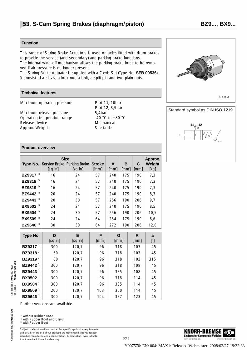
53. S-Cam Spring Brakes (diaphragm/piston) BZ9..., BX9...
www.knorr-bremse.com www.knorr-bremsesfn.com
KNORR-BREMSESystems for Commercial Vehicles
Subject to alteration without notice. For specific application requirementsand details on the use of our products we recommend that you request individual consultation and documentation. Reproduction, even extracts,is not permitted. Printed in GermanyC
atal
ogue
No.
: K00
1561
-EN
Sec
tion
No.
: K
0024
87-0
02D
oc. N
o.:
Y01
1370
-EN
-002
53.1
Function
This range of Spring Brake Actuators is used on axles fitted with drum brakesto provide the service (and secondary) and parking brake functions.The internal wind-off mechanism allows the parking brake force to be remo-ved if air pressure is no longer present.The Spring Brake Actuator is supplied with a Clevis Set (Type No. SEB 00536).It consist of a clevis, a lock nut, a bolt, a split pin and two plain nuts.
Technical features
Maximum operating pressure Port 11; 10barPort 12; 8,5bar
Maximum release pressure 5,4barOperating temperature range -40 °C to +80 °CRelease device MechanicalApprox. Weight See table
Product overview
Size Approx.Type No. Service Brake Parking Brake Stroke A B C Weight
[sq in] [sq in] [mm] [mm] [mm] [mm] [kg]
BZ9317 1) 16 24 57 240 175 190 7,3
BZ9318 2) 16 24 57 240 175 190 7,3
BZ9319 2) 16 24 57 240 175 190 7,3
BZ9442 1) 20 24 57 240 175 190 8,3
BZ9443 1) 20 30 57 256 190 206 9,7
BX9502 1) 24 24 57 240 175 190 8,5
BX9504 1) 24 30 57 256 190 206 10,5
BX9509 3) 24 24 64 254 175 190 8,6
BZ9646 1) 30 30 64 272 190 206 12,0
Standard symbol as DIN ISO 1219
11 12
BX 7...
GrF 0392
Type No. D E F G R a[sq in] [sq in] [mm] [mm] [mm] [°]
BZ9317 1) 300 120,7 96 318 103 45
BZ9318 2) 60 120,7 96 318 103 45
BZ9319 2) 60 120,7 96 318 103 315
BZ9442 1) 300 120,7 96 318 108 45
BZ9443 1) 300 120,7 96 335 108 45
BX9502 1) 300 120,7 96 318 114 45
BX9504 1) 300 120,7 96 335 114 45
BX9509 3) 200 120,7 103 300 114 45
BZ9646 1) 300 120,7 104 357 123 45
1) without Rubber Boot2) with Rubber Boot and Clevis3) with Rubber Boot
Further versions are available.
Y007570: EN: 004: MAX1: Released:Webmaster: 2008/02/27-19:32:33

53. S-Cam Spring Brakes (diaphragm/piston) BZ9..., BX9...
www.knorr-bremse.com www.knorr-bremsesfn.com
KNORR-BREMSESystems for Commercial Vehicles
Subject to alteration without notice. For specific application requirementsand details on the use of our products we recommend that you request individual consultation and documentation. Reproduction, even extracts,is not permitted. Printed in GermanyC
atal
ogue
No.
: K00
1561
-EN
Sec
tion
No.
: K
0024
87-0
02D
oc. N
o.:
Y01
1370
-EN
-002
53.2
Dimensions
aD F
A
E
R
B C
M16
x1,5
M16
x1,5
VF 00075/47
G
Performance Charts
Service Brake Parking Brake
BZ9317BZ9318BZ9319
BZ9442
1,1
1,0
0,9
0,8
0,7
0,6
0,5
0,4
0,3
0,2
0,1
0
13000
12000
11000
10000
9000
8000
7000
6000
5000
4000
3000
2000min.57 50 40 30 20 10 0
Return spring force at 20mm stroke: F= 340N
Vol
ume
[dm
3 ] Volume
Ser
vice
bra
ke o
utpu
t [N
]
Stroke [mm]
6,5 bar
VF 00075/70 EN
VF 00075/72 EN
1,0
1,1
0,9
0,8
0,7
0,6
0,5
0,4
0,3
0,2
0,1
0
14000
15000
13000
12000
11000
10000
9000
8000
7000
6000
5000
4000min.57 50 40 30 20 10 0
Return spring force at 20mm stroke: F= 340N
Vol
ume
[dm
3 ]
Volume
Ser
vice
bra
ke o
utpu
t [N
]
Stroke [mm]
6,5 bar
13000
12000
11000
10000
9000
8000
7000
6000
5000
4000
3000
2000min.57 50 40 30 20 10 0
Required release pressure: 5,1 ±0,3 bar
Stroke[mm]
��
��10970
9730
6170
5340
VF 00075/71 EN
Par
king
bra
ke o
utpu
t [N
]
��
��
12000
11000
10000
9000
8000
7000
6000
5000
4000
3000
2000min.57 50 40 30 20 10 0
Required release pressure: 5,1 ±0,3 bar
Stroke [mm]
10970
9730
6170
5340
Par
king
bra
ke o
utpu
t [N
]
VF 00075/73 EN
Y007570: EN: 004: MAX1: Released:Webmaster: 2008/02/27-19:32:33

53. S-Cam Spring Brakes (diaphragm/piston) BZ9..., BX9...
www.knorr-bremse.com www.knorr-bremsesfn.com
KNORR-BREMSESystems for Commercial Vehicles
Subject to alteration without notice. For specific application requirementsand details on the use of our products we recommend that you request individual consultation and documentation. Reproduction, even extracts,is not permitted. Printed in GermanyC
atal
ogue
No.
: K00
1561
-EN
Sec
tion
No.
: K
0024
87-0
02D
oc. N
o.:
Y01
1370
-EN
-002
53.3
Performance chart - continued -
Service Brake Parking Brake
BZ9443
BX9502BX9504
BX9509BZ9646
1,0
0,9
0,8
0,7
0,6
0,5
0,4
0,3
0,2
0,1
13000
12000
11000
10000
9000
8000
7000
6000
5000
4000min.57 50 40 30 20 10 0
Return spring force at 20mm stroke: F= 340N
Vol
ume
[dm
3 ]
Volume
Ser
vice
bra
ke o
utpu
t [N
]
Stroke [mm]
6,5 bar
VF 00075/74 EN
VF 00075/76 EN
1,0
1,1
0,9
0,8
0,7
0,6
0,5
0,4
0,3
0,2
0,1
0
14000
15000
13000
12000
11000
10000
9000
8000
7000
6000
5000
4000min.57 50 40 30 20 10 0
Return spring force at 20mm stroke: F= 180N
Vol
ume
[dm
3 ]
Volume
Ser
vice
bra
ke o
utpu
t [N
]
Stroke [mm]
6,8bar
VF 00075/78 EN
2,0
1,8
1,6
1,4
1,2
1,0
0,8
0,6
0,4
0,2
0
15000
14000
13000
12000
11000
10000
9000
8000
7000
6000
min.64 5060 40 30 20 10 0
Return spring force at 20mm stroke: F= 300N
Vol
ume
[dm
3 ]
Volume Ser
vice
bra
ke o
utpu
t [N
]
Stroke [mm]
6,5 barBZ 9646
5000
4000
BX 9509
Volume
1,8
1,6
1,4
1,2
1,0
0,8
0,6
0,4
0,2
0
Vol
ume
[dm
3 ]
Volum
en
15000
14000
13000
12000
11000
10000
9000
8000
7000
6000min.57 50 40
4530 20 10 0
Required release pressure: 5,1 ±0,3 bar
Stroke [mm]
11500
9530
Par
king
bra
ke o
utpu
t [N
]
VF 00075/75 EN
���
12000
11000
10000
9000
8000
7000
6000
5000
4000min.57 50 40
4530 20 10 0
Required release pressure: 5,5 ±0,3 bar
Stroke [mm]
10970
9730
6170
5340
Par
king
bra
ke o
utpu
t [N
]
VF 00075/77 EN
1,4
1,2
1,0
0,8
0,6
0,4
0,2
1,6
Vol
ume
[dm
3 ] 11500
9530
13000
0
1,8
Volum
en
BX 9502
BX 9504
��
��
15000
14000
13000
12000
11000
10000
9000
8000
7000
6000
min.64 5060 40
4257
30 20 10 0
Required release pressure: 5,1 ±0,3 bar
Stroke [mm]
13920
12230
9240
8190
Par
king
bra
ke o
utpu
t [N
]
VF 00075/79 EN
��
��
5000
4000
6170
5340
10970
9730
BZ 9646
BX 9509
Y007570: EN: 004: MAX1: Released:Webmaster: 2008/02/27-19:32:33

For reliable and safe mounting of Spring Brakes, please note the following points:
• Use suitable mounting bracket with adequate stability (material thickness)
• Hole dimensions according to DIN
• Plain mounting face, only primed (maximum thickness 0,1mm), not final coated
• Direct contact of the full surface of the Spring Brake mounting face must be made with the mounting bracket. No spacing washers, adapter plates or other elements are allowed.
• Ensure adequate clearance is provided behind the actuator to allow the Wind-off Bolt to be unscrewed.
• Check length of Push Rod, it may need to be shortened.
• The angle between Push Rod and Slack Adjuster and between Push Rod and mounting bracket should be approximately 90 deg. when the Push Rod is at its mid-stroke position.
• During installation, the Slack Adjuster should be rotated towards the Clevis to insert the Clevis Pin. On no account should the Push Rod be pulled out from the Actuator to meet the Slack Adjuster.
• Maximum pivoting angle of Push Rod in all directions = 3°
• For mounting studs, nuts and plain washers must be used.
• General requirements of mechanical engineering concerning stepwise tightening must be followed
• Tightening torque 180+20Nm
• For further information please contact the Spring Brake, axle or trailer manufacturer.
Winding-off the Power Spring
In case of failure in the air system, to release the actuator’s spring force:
• Turn nut (A/F 24mm) at the rear of the actuator in an anti-clockwise direction.
Attention: Use only the correct sized ring or open-ended spanner!
Attention: The Spring Brake contains very high spring loads and it is strongly recommended that you do not undertakeany disassembly work. If this is to be undertaken, use only the correct tools.
53. S-Cam Spring Brakes (diaphragm/piston) BZ9..., BX9...
www.knorr-bremse.com www.knorr-bremsesfn.com
KNORR-BREMSESystems for Commercial Vehicles
Subject to alteration without notice. For specific application requirementsand details on the use of our products we recommend that you request individual consultation and documentation. Reproduction, even extracts,is not permitted. Printed in GermanyC
atal
ogue
No.
: K00
1561
-EN
Sec
tion
No.
: K
0024
87-0
02D
oc. N
o.:
Y01
1370
-EN
-002
53.4
Installation and Mounting instructions
Y007570: EN: 004: MAX1: Released:Webmaster: 2008/02/27-19:32:33

54. Air Disc Spring Brakes (diaphragm/diaphragm) BS7...
www.knorr-bremse.com www.knorr-bremsesfn.com
KNORR-BREMSESystems for Commercial Vehicles
Subject to alteration without notice. For specific application requirementsand details on the use of our products we recommend that you request individual consultation and documentation. Reproduction, even extracts,is not permitted. Printed in GermanyC
atal
ogue
No.
: K00
1561
-EN
Sec
tion
No.
: K
0024
88-0
02D
oc. N
o.:
Y01
1371
-EN
-002
54.1
Function
This range of Spring Brakes is used on axles fitted with air disc brakes andprovides the service (and secondary) and parking brake functions.The internal wind off mechanism allows the parking brake force to be removedif air pressure is no longer present.
The Spring Brakes have a mounting seal integrated in the non-pressure housing which prevents the entry of dirt or water into the caliper.
Technical Features
Maximum operating pressure 10 barOperating temperature range -40 °C to +80 °CSealing of secondary chamber Rubber BootPivoting angle of piston rod in all directions 4°Maximum required release pressure 5,5 barRelease device MechanicalMaximum release torque 47 NmApprox. weight See table
Product overview
Type No. Part No. Type [sq in] Approx. Weight [kg] TÜV-Inspection Report
BS7304 II38524F 16/24 6,9 BZ 105.0
BS7305 II38564F 16/24 7,0 BZ 105.0
BS7309 II39355F 16/24 7,0 BZ 114.1
BS7351 II38525F 18/24 7,0 BZ 105.0
Standard symbol as DIN ISO 1219
11 12
BX 7...
VF 00199_6
Further versions are available.
Actuator Mounting Kit available comprising 2 off self-locking nuts: Part Number II36860.
Y007570: EN: 004: MAX1: Released:Webmaster: 2008/02/27-19:32:33

54. Air Disc Spring Brakes (diaphragm/diaphragm) BS7...
www.knorr-bremse.com www.knorr-bremsesfn.com
KNORR-BREMSESystems for Commercial Vehicles
Subject to alteration without notice. For specific application requirementsand details on the use of our products we recommend that you request individual consultation and documentation. Reproduction, even extracts,is not permitted. Printed in GermanyC
atal
ogue
No.
: K00
1561
-EN
Sec
tion
No.
: K
0024
88-0
02D
oc. N
o.:
Y01
1371
-EN
-002
54.2
KN
OR
R-D
AH
LTy
peJ/
A
M16x1,5Tightening torque
180 +30 Nm
M16x1,5Tightening torque
max. 13 Nm
SERV
ICE
EMER
GENC
Y
C
F
VF 00075/158 EN
Holder forwind-off bolt
43
15 ±0,5
BallR 8
B
36
αβ
Ø14
4
A
R
2516
DE
max.
max
.
Gm
ax.
H
Dimensions
Type No. Type A B max. C D E F max. G max. H R α β[sq in] [mm] [mm] [mm] [mm] [mm] [mm] [mm] [mm] [mm] [°] [°]
BS7304 16/24 120,7 330 226 95 120 149,4 191,3 86 106 90 270
BS7305 16/24 120,7 330 226 95 120 149,4 191,3 86 106 -90 0
BS7309 16/24 120,7 330 226 95 120 149,4 191,3 86 106 90 270
BS7351 18/24 120,7 330 226 95 120 149,4 191,3 86 106 90 270
Y007570: EN: 004: MAX1: Released:Webmaster: 2008/02/27-19:32:33

54. Air Disc Spring Brakes (diaphragm/diaphragm) BS7...
www.knorr-bremse.com www.knorr-bremsesfn.com
KNORR-BREMSESystems for Commercial Vehicles
Subject to alteration without notice. For specific application requirementsand details on the use of our products we recommend that you request individual consultation and documentation. Reproduction, even extracts,is not permitted. Printed in GermanyC
atal
ogue
No.
: K00
1561
-EN
Sec
tion
No.
: K
0024
88-0
02D
oc. N
o.:
Y01
1371
-EN
-002
54.3
Performance Charts
1,1
1,0
0,9
0,8
0,7
0,6
0,5
0,4
0,3
0,2
0,1
0
14000
13000
12000
11000
10000
9000
8000
7000
6000
5000
4000
3000min.57 50 40 30 20 10 0
Return spring force at 0mm stroke: F= 150 ±20 N
Vol
ume
[dm
3 ]
Ser
vice
bra
ke o
utpu
t [N
]
Stroke [mm]
8,5 bar
VF 00075/160 EN
Volume
1,2
1,1
1,0
0,9
0,8
0,7
0,6
0,5
0,4
0,3
0,2
0,1
13000
12000
11000
10000
9000
8000
7000
6000
5000
4000
3000
2000min.57 50 40 30 20 10 0
Return spring force at 0mm stroke: F= 150 ±20 N
Vol
ume
[dm
3 ]
Ser
vice
bra
ke o
utpu
t [N
]
Stroke [mm]
6,5 bar
VF 00075/162 EN
Volume
1,1
1,0
0,9
0,8
0,7
0,6
0,5
0,4
0,3
0,2
0,1
0
14000
13000
12000
11000
10000
9000
8000
7000
6000
5000
4000
3000min.57 50 40 30 20 10 0
Return spring force at 0mm stroke: F= 150 ±20 N
Vol
ume
[dm
3 ]
Ser
vice
bra
ke o
utpu
t [N
]
Stroke [mm]
8,5 bar
VF 00075/163 EN
Volume
BS7304BS7305
BS7309
BS7351
Service Brake Parking Brake
Parking brake output stroke 30 mm: 5926N
Parking brake output stroke 30 mm: 5736N
Parking brake output stroke 30 mm: 5736N
Y007570: EN: 004: MAX1: Released:Webmaster: 2008/02/27-19:32:33

54. Air Disc Spring Brakes (diaphragm/diaphragm) BS7...
www.knorr-bremse.com www.knorr-bremsesfn.com
KNORR-BREMSESystems for Commercial Vehicles
Subject to alteration without notice. For specific application requirementsand details on the use of our products we recommend that you request individual consultation and documentation. Reproduction, even extracts,is not permitted. Printed in GermanyC
atal
ogue
No.
: K00
1561
-EN
Sec
tion
No.
: K
0024
88-0
02D
oc. N
o.:
Y01
1371
-EN
-002
54.4
Detailed information concerning the mounting of disc brake actuators can befound in the service manual Y006471.
Special Note: If the actuator is supplied with the drain holes plugged, removethe lowest plug (as viewed when the actuator is installed).
Winding-off the Power Spring
In case of failure in the air system, to release the actuator’s spring force:
• Ensure wheels are chocked.
• Remove Wind-off Bolt (1) from its holder (4).
• Unclip closure cap (2).
• Fully insert "T” drive end of Wind-off Bolt into actuator end (3) - and engage with internal slot.
• Fit washer and nut (5).
• Rotate the nut (A/F 3/4”) in a clockwise direction.
Attention: Use only the correct sized ring or open-ended spanner!
Attention: The Spring Brake contains very high spring loads and it is strongly recommended that you do not undertakeany disassembly work. If this is to be undertaken, use only the correct tools.
Installation and Mounting instructions
P3430/53_BS
Y007570: EN: 004: MAX1: Released:Webmaster: 2008/02/27-19:32:33

55. Air Disc Spring Brakes (diaphragm/piston) BS9...
www.knorr-bremse.com www.knorr-bremsesfn.com
KNORR-BREMSESystems for Commercial Vehicles
Subject to alteration without notice. For specific application requirementsand details on the use of our products we recommend that you request individual consultation and documentation. Reproduction, even extracts,is not permitted. Printed in GermanyC
atal
ogue
No.
: K00
1561
-EN
Sec
tion
No.
: K
0024
89-0
02D
oc. N
o.:
Y01
1372
-EN
-002
55.1
Function
This range of Spring Brakes is used on axles fitted with air disc brakes andprovides the service (and secondary) and parking brake functions.The internal wind-off mechanism allows the parking brake force to be removed if air pressure is no longer present.
The Spring Brakes have a mounting seal integrated in the non-pressure housing which prevents the entry of dirt or water into the caliper.
Technical Features
Maximum operating pressure Connection 11, 10,2 barConnection 12, 8,5 bar
Operating temperature range -40 °C to +80 °CSealing of non-pressure housing Rubber BootPivoting angle of piston rod in all directions 4°Maximum required release pressure 5,1 barRelease device MechanicalMaximum release torque 35 NmApprox. Weight See table
Product overview
Standard symbol as DIN ISO 1219
11 12
BX 7...
GrF 0367
Further versions are available.
Actuator Mounting Kit available comprising 2 off self-locking nuts: Part Number II36080.
Type No. Part No. Type [sq in] Weight [kg] TÜV-Inspection Report
BS9297 II31783000 14/16 6,9 353-437-97FBTN
BS9304 II30619000 16/24 7,4 353-440-97FBTN
BS9349 II31663000 18/16 6,9 353-439-97FBTN
BS9397 II31227000 16/16 6,8 353-438-97FBTN
BS9503 II31408000 24/24 7,7 356-310-94FBTN
BS9404 II31407000 20/24 7,9 356-314-94FBTN
BS9451 II31226000 22/24 7,5 356-309-94FBTN
Y007570: EN: 004: MAX1: Released:Webmaster: 2008/02/27-19:32:33

55. Air Disc Spring Brakes (diaphragm/piston) BS9...
www.knorr-bremse.com www.knorr-bremsesfn.com
KNORR-BREMSESystems for Commercial Vehicles
Subject to alteration without notice. For specific application requirementsand details on the use of our products we recommend that you request individual consultation and documentation. Reproduction, even extracts,is not permitted. Printed in GermanyC
atal
ogue
No.
: K00
1561
-EN
Sec
tion
No.
: K
0024
89-0
02D
oc. N
o.:
Y01
1372
-EN
-002
55.2
D
C
E
F G m
ax
M16
x1,5
VF 00075/106 ÄI 01 EN
B max
43
36
15 ±0,5
BallR 8
R
Pivoting point of push rod,chamber unpressurized
M16x1,5; 14 deepTightening torque
40 Nm
11
12
Installed position vertical ±30°
α β
A H
Dimensions
Type No. Typ A B max. C D E F G max. H R α β[sq in] [mm] [mm] [mm] [mm] [mm] [mm] [mm] [mm] [mm] [°] [°]
BS9297 14/16 120,7 327 246 96 106 160 176 81 43 90 45
BS9304 16/24 120,7 318 240 96 106 175 191 90 43 90 45
BS9349 18/16 120,7 327 246 96 106 160 176 81 50 90 45
BS9397 16/16 120,7 327 246 96 106 160 176 81 47 90 45
BS9404 20/24 120,7 318 240 96 111 175 191 90 52 90 45
BS9451 22/24 120,7 318 240 96 108 175 191 90 54 90 45
BS9503 24/24 120,7 318 240 96 117 175 191 90 57,5 90 45
Y007570: EN: 004: MAX1: Released:Webmaster: 2008/02/27-19:32:33

55. Air Disc Spring Brakes (diaphragm/piston) BS9...
www.knorr-bremse.com www.knorr-bremsesfn.com
KNORR-BREMSESystems for Commercial Vehicles
Subject to alteration without notice. For specific application requirementsand details on the use of our products we recommend that you request individual consultation and documentation. Reproduction, even extracts,is not permitted. Printed in GermanyC
atal
ogue
No.
: K00
1561
-EN
Sec
tion
No.
: K
0024
89-0
02D
oc. N
o.:
Y01
1372
-EN
-002
55.3
Performance Charts
1,1
1,0
0,9
0,8
0,7
0,6
0,5
0,4
0,3
0,2
0,1
0
11000
10000
9000
8000
7000
6000
5000
4000
3000
2000
1000
0min.57 50 40 30 20 10 0
Return spring force at 20mm stroke: F= 200N
Vol
ume
[dm
3 ]
Ser
vice
bra
ke o
utpu
t [N
]
Stroke [mm] VF 00075/107 ÄI 01 EN
6,5 bar
Volume
1,8
1,6
1,4
1,2
1,0
0,8
0,6
0,4
0,2
0
Vol
ume
[dm
3 ]
10000
9000
8000
7000
6000
5000
4000
3000
2000
1000
min. 5750 40
4530 20 10 0
Required release pressure: 5,2 ±0,3 bar
Stroke [mm]
6995
4670
Par
king
bra
ke o
utpu
t [N
]
VF 00075/108 EN
Volume
1,1
1,0
0,9
0,8
0,7
0,6
0,5
0,4
0,3
0,2
0,1
0
13000
12000
11000
10000
9000
8000
7000
6000
5000
4000
3000
2000min.57 50 40 30 20 10 0
Return spring force at 20mm stroke: F= 200N
Vol
ume
[dm
3 ]
Ser
vice
bra
ke o
utpu
t [N
]
Stroke [mm] VF 00075/109 EN
6,5 barVolume
1,8
1,6
1,4
1,2
1,0
0,8
0,6
0,4
0,2
0
Vol
ume
[dm
3 ]
13000
12000
11000
10000
9000
8000
7000
6000
5000
4000
min. 5750 40
4530 20 10 0
Required release pressure: 5,1 ±0,3 bar
Stroke [mm]
8700
6830
Par
king
bra
ke o
utpu
t [N
]
VF 00075/110 EN
Volum
e
1,1
1,0
0,9
0,8
0,7
0,6
0,5
0,4
0,3
0,2
0,1
0
13000
12000
11000
10000
9000
8000
7000
6000
5000
4000
3000
2000min.57 50 40 30 20 10 0
Return spring force at 20mm stroke: F= 200N
Vol
ume
[dm
3 ]
Ser
vice
bra
ke o
utpu
t [N
]
Stroke [mm] VF 00075/111 ÄI 01 EN
6,5 barVolume
1,1
1,0
0,9
0,8
0,7
0,6
0,5
0,4
0,3
0,2
0,1
0
13000
12000
11000
10000
9000
8000
7000
6000
5000
4000
3000
2000min.57 50 40 30 20 10 0
Return spring force at 20mm stroke: F= 200N
Vol
ume
[dm
3 ]
Ser
vice
bra
ke o
utpu
t [N
]
Stroke [mm] VF 00075/109 EN
6,5 barVolume
1,8
1,6
1,4
1,2
1,0
0,8
0,6
0,4
0,2
0
Vol
ume
[dm
3 ]
10000
9000
8000
7000
6000
5000
4000
3000
2000
1000
min. 5750 40
4530 20 10 0
Required release pressure: 5,2 ±0,3 bar
Stroke [mm]
6995
4670
Par
king
bra
ke o
utpu
t [N
]
VF 00075/108 EN
Volume
BS9297
BS9304
BS9349
BS9397
Service Brake Parking Brake
1,8
1,6
1,4
1,2
1,0
0,8
0,6
0,4
0,2
0
Vol
ume
[dm
3 ]
10000
9000
8000
7000
6000
5000
4000
3000
2000
1000
min. 5750 40
4530 20 10 0
Required release pressure: 5,2 ±0,3 bar
Stroke [mm]
6995
4670
Par
king
bra
ke o
utpu
t [N
]
VF 00075/108 EN
Volume
Y007570: EN: 004: MAX1: Released:Webmaster: 2008/02/27-19:32:33

55. Air Disc Spring Brakes (diaphragm/piston) BS9...
www.knorr-bremse.com www.knorr-bremsesfn.com
KNORR-BREMSESystems for Commercial Vehicles
Subject to alteration without notice. For specific application requirementsand details on the use of our products we recommend that you request individual consultation and documentation. Reproduction, even extracts,is not permitted. Printed in GermanyC
atal
ogue
No.
: K00
1561
-EN
Sec
tion
No.
: K
0024
89-0
02D
oc. N
o.:
Y01
1372
-EN
-002
55.4
Performance Charts - continued -
1,1
1,0
0,9
0,8
0,7
0,6
0,5
0,4
0,3
0,2
0,1
0
14000
13000
12000
11000
10000
9000
8000
7000
6000
5000
4000
3000min.57 50 40 30 20 10 0
Return spring force at 20mm stroke: F= 200N
Vol
ume
[dm
3 ]
Ser
vice
bra
ke o
utpu
t [N
]
Stroke [mm] VF 00075/113 EN
6,5 barVolume
1,1
1,0
0,9
0,8
0,7
0,6
0,5
0,4
0,3
0,2
0,1
0
14000
13000
12000
11000
10000
9000
8000
7000
6000
5000
4000
3000min.57 50 40 30 20 10 0
Return spring force at 20mm stroke: F= 200N
Vol
ume
[dm
3 ]
Ser
vice
bra
ke o
utpu
t [N
]
Stroke [mm] VF 00075/117 EN
6,5 barVolume
1,8
1,6
1,4
1,2
1,0
0,8
0,6
0,4
0,2
0
Vol
ume
[dm
3 ]
13000
12000
11000
10000
9000
8000
7000
6000
5000
4000
min. 5750 40
4530 20 10 0
Required release pressure: 5,1 ±0,3 bar
Stroke [mm]
8700
6830
Par
king
bra
ke o
utpu
t [N
]
VF 00075/110 EN
Volum
e
1,1
1,0
0,9
0,8
0,7
0,6
0,5
0,4
0,3
0,2
0,1
0
15000
14000
13000
12000
11000
10000
9000
8000
7000
6000
5000
4000min.57 50 40 30 20 10 0
Return spring force at 20mm stroke: F= 200N
Vol
ume
[dm
3 ]
Ser
vice
bra
ke o
utpu
t [N
]
Stroke [mm] VF 00075/118 ÄI 01 EN
6,5 barVolume
BS9404
BS9451
BS9503
1,8
1,6
1,4
1,2
1,0
0,8
0,6
0,4
0,2
0
Vol
ume
[dm
3 ]
13000
12000
11000
10000
9000
8000
7000
6000
5000
4000
min. 5750 40
4530 20 10 0
Required release pressure: 5,1 ±0,3 bar
Stroke [mm]
8700
6830
Par
king
bra
ke o
utpu
t [N
]
VF 00075/110 EN
Volum
e
1,8
1,6
1,4
1,2
1,0
0,8
0,6
0,4
0,2
0
Vol
ume
[dm
3 ]
13000
12000
11000
10000
9000
8000
7000
6000
5000
4000
min. 5750 40
4530 20 10 0
Required release pressure: 5,1 ±0,3 bar
Stroke [mm]
8700
6830
Par
king
bra
ke o
utpu
t [N
]
VF 00075/110 EN
Volum
e
Service Brake Parking Brake
Y007570: EN: 004: MAX1: Released:Webmaster: 2008/02/27-19:32:33

55. Air Disc Spring Brakes (diaphragm/piston) BS9...
www.knorr-bremse.com www.knorr-bremsesfn.com
KNORR-BREMSESystems for Commercial Vehicles
Subject to alteration without notice. For specific application requirementsand details on the use of our products we recommend that you request individual consultation and documentation. Reproduction, even extracts,is not permitted. Printed in GermanyC
atal
ogue
No.
: K00
1561
-EN
Sec
tion
No.
: K
0024
89-0
02D
oc. N
o.:
Y01
1372
-EN
-002
55.5
Detailed information concerning the mounting of disc brake actuators can befound in the service manual Y006471.
Special Note: If the actuator is supplied with the drain holes plugged, remove lowest plug (as viewed when the actuator is installed).
Winding-off the Power Spring
In case of failure in the air system, to release the actuator’s spring force:
• Ensure wheels are chocked
• Turn nut (A/F 24mm) at the rear of the actuator in an anti-clockwise direction.
Attention: Use only the correct sized ring or open-ended spanner!
Attention: The Spring Brake contains very high spring loads and it is strongly recommended that you do not undertakeany disassembly work. If this is to be undertaken, use only the correct tools.
Installation and Mounting instructions
Y007570: EN: 004: MAX1: Released:Webmaster: 2008/02/27-19:32:33

60. Air Disc Brake SN5..., SN6..., SN7..., SK7...
www.knorr-bremse.com www.knorr-bremsesfn.com
KNORR-BREMSESystems for Commercial Vehicles
Subject to alteration without notice. For specific application requirementsand details on the use of our products we recommend that you request individual consultation and documentation. Reproduction, even extracts,is not permitted. Printed in Germany
60.1
Cat
alog
ue N
o.: K
0015
61-E
NS
ectio
n N
o.:
K00
2490
-002
Doc
. No.
:Y
0113
73-E
N-0
02
Function
The SN range of Disc Brakes is a natural evolution of the SB range.The brake is designed with a floating caliper and can be activated by either aBrake Chamber to provide the service brake function or a Spring Brake toprovide the service and parking brake functions.
For trailers with a wheel size of 22,5", an Air Disc Brake has been designedspecifically for trailer applications.This brake is called SK7... and its main features are high fade resistance andlow weight. Additionally, the SK7... has 2mm more brake pad thickness compared with the SN6... and SN7... versions.
Main features
• Monobloc body• Compact design• Reduced weight• Optimised sealing at the caliper to actuator interface
and the fixed Guide Pin• Optimised protection of the Guide Pins• Interchangeability between SN and SB• Possibility of pad wear control via Pad Wear Indicators
Technical features
SN5... SN6... SN7... SK7...
Suitable for wheel rim size [inch] 17,5 19,5 22,5 22,5
Internal transmission ratio 10 15,6 15,6 15,6
Rotor disc diameter [mm] 335 377 430 430
Rotor disc thickness (new) [mm] 34 45 45 45
Rotor disc thickness (min) [mm] 28 37 37 37
Pad friction material thickness (new) [mm] 19 21 21 23
Pad friction material thickness (min) [mm] 2 2 2 2
Brake efficiency [%] 95 95 95 95
Weight without Disc, including pads [kg] 23 33,5 44,6 35,7
Seal Diaphragm Yes Yes Yes Yes(caliper to cylinder interface)
Further information about Air Disc Brakes, Discs and Actuators,as well as Brake Pads, Service Kits and
Service Tools can be found in the Disc Brake Catalogue (identification number Y000875),
in the Service Manual (identification number Y006471),and in the CD product catalogue (identification number Y001627).
VF 00197_5
VF 00197_4
SN5...
SN6..., SN7..., SK7...
Y007570: EN: 004: MAX1: Released:Webmaster: 2008/02/27-19:32:33

Versions Part Number for Disc Brake:
Pad Wear Kit for K000461 SB7... / SN7...
retrofitting (long version) K000670 SB6... / SN6... / SK7...
Pad Wear Kit for pad change (long version) K000937and for retrofitting SN.... SB7... / SN7... / SK7...
Pad Wear Kit for pad SB6... / SN6...change (short version) K000938and for retrofitting SN....
See
Figu
re 1
See
Fig
ure
2
61. Brake Pad Wear Indicator Kit K000...
www.knorr-bremse.com www.knorr-bremsesfn.com
KNORR-BREMSESystems for Commercial Vehicles
Subject to alteration without notice. For specific application requirementsand details on the use of our products we recommend that you request individual consultation and documentation. Reproduction, even extracts,is not permitted. Printed in Germany
61.1
Cat
alog
ue N
o.: K
0015
61-E
NS
ectio
n N
o.:
K00
2491
-002
Doc
. No.
:Y
0113
74-E
N-0
02
Function
The Brake Pad Wear Indicator Kit is used for monitoring the Pad frictionmaterial thickness.
Wear is "monitored" via two sensors which are located directly into the cut-outs of the inner and outer Brake Pads.
When the wear limit (2mm remaining pad thickness) is reached, the sensorscontact the Brake Disc and, depending on the version, make or break anelectrical circuit. This electrical change can be used by the Electronic BrakingSystem for pad wear control or simply to provide a visual warning in the cabthat the Pads must be replaced.
There are different warning displays for pad wear control, that can be mountedon the trailer (see page 40.2, 40.26 and 40.28)
Product overview
Figure 1(old type)
Figure 2(new type)
VF00075/232
VF00075/233
Y007570: EN: 004: MAX1: Released:Webmaster: 2008/02/27-19:32:33

61. Brake Pad Wear Indicator Kit K000...
www.knorr-bremse.com www.knorr-bremsesfn.com
KNORR-BREMSESystems for Commercial Vehicles
Subject to alteration without notice. For specific application requirementsand details on the use of our products we recommend that you request individual consultation and documentation. Reproduction, even extracts,is not permitted. Printed in Germany
61.2
Cat
alog
ue N
o.: K
0015
61-E
NS
ectio
n N
o.:
K00
2491
-002
Doc
. No.
:Y
0113
74-E
N-0
02
Contents of Kits K000...
Contents Item ...461 ...670 ...932 ...933 ...937 ...938
Pad Wear Kit (682mm) 101 X X – – X –
Pad Wear Kit (294mm) 101 – – X X – X
Cable Guide 104 X X X X X X
Protection Plate 105 X X X X X X
11 X X X X – –
Pad Retainer Kit 26 X X X X – –
44 X X X X – –
45 X X X X – –
List of contents – X X X X X X
Packing – X X X X X X
To be used for See Figure 1 See Figure 2
pad retainer type
Figure 1(old type)
Figure 2(new type)
VF00075/232
VF00075/233
TÜV - Report:No.: TÜH ATC-TB 2003 - 080.80
Y007570: EN: 004: MAX1: Released:Webmaster: 2008/02/27-19:32:33

70. Air Suspension Levelling Valves SV13.., SV14..
www.knorr-bremse.com www.knorr-bremsesfn.com
KNORR-BREMSESystems for Commercial Vehicles
Subject to alteration without notice. For specific application requirementsand details on the use of our products we recommend that you request individual consultation and documentation. Reproduction, even extracts,is not permitted. Printed in Germany
70.1
Sec
tion
No.
: K
0024
92-0
01D
oc. N
o.:
Y01
1375
-EN
-001
Cat
alog
ue N
o.: K
0015
61-E
N
Schaltzeichen nach DIN ISO 1219
SV1395SV1460 SV1418
SV1441 SV1465SV1447 SV1485
SV1466
11
3
21
SV 1307
11
3
21
SV 1418
SV 1441
4
2121
3
11
SV 14614
2121
233
11
12
SV 1463
2121
233
11
12
The rubber joint at the lower end of the vertical linkage is available separately.Part Number: K001406
1) Standard valve without additional features2) Without additional features, higher volumetric flow3) Standard valve without additional features, plastic body4) Height Limitation adjustable, see adjustment instructions5) Ports 12 and 23 are fitted with blanking plugs
Function
On vehicles fitted with air suspension, the Levelling Valve ensures that the axleSuspension Air Bags maintain a constant chassis height irrespective of thevehicle load.
Versions with the "Height Limitation” feature prevent the chassis height beingmanually raised above a set limit.
Versions with the "Second Ride Height” feature allow the driver to pneumati-cally signal the valve and raise the chassis to an alternative ride height.
Cross Throttling prevents the rapid flow of air between the two outlet ports 21 (left and right side of the vehicle).
Technical Features
Maximum Operating Pressure: 12 barOperating Temperature Range: -40 °C to +80 °CApproximate weight: 0.7KgLever length: 300 mmLever design: Round, with rubber jointMedium: Compressed Air
Product Overview
Type No. Part Number Replaces Second Ride Height SecondaryHeight Limitation Exhaust
(pre- set) (adjustable)
SV13951) II19425 SV1307 – – –SV14182) I99633 – – – –SV1441 II30531 – 12° – –SV1447 II34910 – 17,5° – –SV14603) II36088 – – – –SV1465 II36114 SV1440, 61 12° 20°-50° 4) WithSV1466 II36115 SV1410, 63 – 20°-50° 4) WithSV1485 K000367 – 10° 20°-50° 4) WithSV14855) K002647 – 10° 20°-50° 4) With
Y007570: EN: 004: MAX1: Released:Webmaster: 2008/02/27-19:32:33

70. Air Suspension Levelling Valves SV13.., SV14..
Subject to alteration without notice. For specific application requirements
and details on the use of our products we recommend that you request
individual consultation and documentation. Reproduction, even extracts,
is not permitted. Printed in Germany
70.2
Cata
logue N
o.: K
0015
61S
ection N
o.:
K00
2492
-000
Doc.
No.:
Y01
1375
-EN
-000
Instructions for adjusting the height limitation(applies to the following levelling valves: SV1461, SV1462, SV1463, SV1466 and SV1485)
Levelling valves with Height Limitation shut off the air supply to the Raise/Lower valve at a certain
angle of the lever and thereby limit the maximum chassis height.
This angle is supplied pre-set to 25° but can be adjusted within the range 20° to 50°.
Note:
If the adjustment range is not sufficient, the lever length can be changed.
(reference pages 70.3, 70.4)
The adjustment is done as follows:
1. Pressurise ports 11 and 12 with minimum 6 bar
2. Pull off the protection cap from the adjustment screw.See Graphic 1
3. Raise the chassis with the Raise/Lower valveSee Graphic 2
4. Is the maximum permitted height being exceeded?
no yes
5. Raise Chassis until height limitation becomes activeSee Graphic 2
6. Leave Raise/Lower Valve in "Raise”-position
7. Turn adjustment screw - see NOTE: - with a 4mm Allen Key• clockwise to increase maximum chassis height• counter-clockwise to decrease maximum chassis height
8. Re-check the adjusted height limitation by lowering the chassis and raising it again
9. Move Raise/Lower Valve lever back to driving positionSee Graphic 2
10. Replace protection cap and ensure correct fittingSee Graphic 1
4c. Turn the adjustment screw
- see NOTE: -
of the levelling valve
with a 4mm Allen Key for half
a turn anti-clockwise
See Graphic 1
4b. Lower the chassis several cm
See Graphic 2
4a. Immediately move Raise/LowerValve to "STOP” positionSee
Graphic 2
NOTE: Caution! Max. torque 1.2 Nm!Turning the screw by 360° is equiva-
lent to approximately 11° changeof the lever angle
Graphic 1
Graphic 21) For some part numbers the control logic is vice versa
Push in
for adjustment
Raise1)
STOP
Lower1)
Y007570: EN: 004: MAX1: Released:Webmaster: 2008/02/27-19:32:33

70. Air Suspension Levelling Valves SV13.., SV14..
www.knorr-bremse.com www.knorr-bremsesfn.com
KNORR-BREMSESystems for Commercial Vehicles
Subject to alteration without notice. For specific application requirementsand details on the use of our products we recommend that you request individual consultation and documentation. Reproduction, even extracts,is not permitted. Printed in Germany
70.3
Sec
tion
No.
: K
0024
92-0
01D
oc. N
o.:
Y01
1375
-EN
-001
Cat
alog
ue N
o.: K
0015
61-E
N
Second Ride Height and Height Limitation features:Calculation of the correct lever length
When the Second Ride Height feature is activated, further angular travel of the lever is permitted and the chassis risesto a higher position; the increase in angle is a fixed value for each valve. If the lever length is changed, the second rideheight can be further adjusted.
The Height Limitation feature is adjusted using the integrated hexagon socket (see instructions on page 70.2). Forcases where the adjustment range is not sufficient, additional height can be achieved by increasing the lever length.The quotient of Lever Length and Height Limitation must be in the range 1.3 to 2.9.
The following formulae for calculating the lever length will give an approximate value for the static condition.
Legend:
L = Lever length of Levelling Valve
RH = Ride Height (height of the chassis while driving with the Levelling Valve lever in the horizontal position)
RH2 = Second Ride Height (increased chassis height above RH when pressurising port 4, e.g. when driving with a lift axle raised)
HL = Height Limitation (maximum possible chassis height above RH whenoperating the Raise/Lower Valve)
VF 00075/96 ÄI 01 EN
HL
RH
RH
2
RH
Type No. Second Ride Height (RH2) Height Limitation (HL)
SV1465 L = 4,8 x RH2 1,3 ≤ ≤ 2,9
SV1466 – 1,3 ≤ ≤ 2,9
SV1485 L = 5,8 x RH2 1,3 ≤ ≤ 2,9
SV1441 L = 4,8 x RH2 –
SV1447 L = 3,3 x RH2 –
Example:Second Ride Height for SV1485:RH2 (requested) = 40 mmHL (requested) = 100 mmL = 5,8 x 40mm = 232 mm
= = 2,32
1,3 ≤ 2,32 ≤ 2,9
Type No. Second Ride Height Height Limitationα β
SV1441 12° –SV1447 17,5° –SV1465 12° 20° - 50°SV1466 – 20° - 50°SV1485 10° 20° - 50°
LHLL
HLL
HL
LHL
232 mm100 mm
When the angle of theheight limitation is reached, thevalve is in the following condition:• connection 11 – 21 closed• connection 12 – 23 closed • secondary exhaust for 23 open
Y007570: EN: 004: MAX1: Released:Webmaster: 2008/02/27-19:32:33

70. Air Suspension Levelling Valves SV13.., SV14..
www.knorr-bremse.com www.knorr-bremsesfn.com
KNORR-BREMSESystems for Commercial Vehicles
Subject to alteration without notice. For specific application requirementsand details on the use of our products we recommend that you request individual consultation and documentation. Reproduction, even extracts,is not permitted. Printed in Germany
70.4
Sec
tion
No.
: K
0024
92-0
01D
oc. N
o.:
Y01
1375
-EN
-001
Cat
alog
ue N
o.: K
0015
61-E
N
Chassis height change x [mm]Lever length L [mm]
5°
10°
15°
20°
25°
35°
45°
30°
40°
50°
50
100
150
200
250
300 0
50
100
150
200
230
X
αL
Example:
Lever length L = 200 mmAngle α =30° } Chassis height change X=100 mm
α =0°
VF 00075/93 ÄI 01 EN
on the basis of a horizontal lever position:x = L x sin α
Lever angle α [°]
Graphic Diagram for determining the Chassis height change "X” and the lever length "L”
Y007570: EN: 004: MAX1: Released:Webmaster: 2008/02/27-19:32:33

70. Air Suspension Levelling Valves SV13.., SV14..
www.knorr-bremse.com www.knorr-bremsesfn.com
KNORR-BREMSESystems for Commercial Vehicles
Subject to alteration without notice. For specific application requirementsand details on the use of our products we recommend that you request individual consultation and documentation. Reproduction, even extracts,is not permitted. Printed in Germany
70.5
Sec
tion
No.
: K
0024
92-0
01D
oc. N
o.:
Y01
1375
-EN
-001
Cat
alog
ue N
o.: K
0015
61-E
N
VF 00075/124 EN
1
Legend: = Free Air in Litres/sec. [l/s] = Lever Deflection in degrees when exhausting [°] = Lever Deflection in degrees when charging [°]
= Volume of flow through one port = Volume of flow through two ports
23
at 6 barsupply pressure}
-α [°] 30 20 10 10 20 30 400 +α [°]
2
4
6
8
1011 2x21
11 1x21
2x21 3
1x21 3
V [l/s]
32
1
40
SV1460
11
-α [°] 30 20 10 10 20 30 400 +α [°]
2
4
6
8
10
11 2x21
11 1x21
2x21 3
1x21 3
V [l/s]
32
1
40
SV1418SV1441SV1447
SV1395
-α [°] 30 20 10 10 20 30 400 +α [°]
11 2x21
11 1x21
2x21 3
1x21 3
1
2
3
4
5
V [l/s]
32
1
40
-α [°] 30 20 10 10 20 30 400 +α [°]
2
4
6
8
1011 2x21
11 1x21
2x21 3
1x21 3
V [l/s]
32
1
40
SV1465SV1466SV1485
Performance Chart
Y007570: EN: 004: MAX1: Released:Webmaster: 2008/02/27-19:32:33

70. Air Suspension Levelling Valves SV13.., SV14..
www.knorr-bremse.com www.knorr-bremsesfn.com
KNORR-BREMSESystems for Commercial Vehicles
Subject to alteration without notice. For specific application requirementsand details on the use of our products we recommend that you request individual consultation and documentation. Reproduction, even extracts,is not permitted. Printed in Germany
70.6
Sec
tion
No.
: K
0024
92-0
01D
oc. N
o.:
Y01
1375
-EN
-001
Cat
alog
ue N
o.: K
0015
61-E
N
6,0 5,8
K
V
Charging
Exhausting
Maximum OperatingAngle 50° above orbelow horizontal
M12x1
,5
42
50
6231
1324 A/Flats
Lever must always be in thesame direction as the locationmark on shaft
4020
300
25
~100
3020
M12x1,5
140
8723
57,5
13
51
VF 00075/1 ÄI 01 EN
SV1395
~
38
±1
Ø 18 ±1
25
16 ±1
21 21
11
Ø 9
,5
Ø 8
,7
8 A/Flats
10 A/Flats(Torque to 10±1 Nm)
Ø 5,8 +0,2
Ø 2
2
For presetting the Valve, the lever can be temporarily held in thehorizontal position by means
of a 4 mm dia. x 20 mm long pin.After setting, the pin MUST be removed
min
35
dia. for 6 dia. shaft
Dimensions
Y007570: EN: 004: MAX1: Released:Webmaster: 2008/02/27-19:32:33

70. Air Suspension Levelling Valves SV13.., SV14..
www.knorr-bremse.com www.knorr-bremsesfn.com
KNORR-BREMSESystems for Commercial Vehicles
Subject to alteration without notice. For specific application requirementsand details on the use of our products we recommend that you request individual consultation and documentation. Reproduction, even extracts,is not permitted. Printed in Germany
70.7
Sec
tion
No.
: K
0024
92-0
01D
oc. N
o.:
Y01
1375
-EN
-001
Cat
alog
ue N
o.: K
0015
61-E
N
VF00075/2 EN
Ø2
0 ±
0,3
SW 24
40 ±0,5
21
M1
2 x
1,5
21
11
3
23 ±
1,1
42
±1
87
,5 ±
2
16
0 ±
3,5
31
±0
,9
Ø2
0 ±
0,3
50 +1 30 +1
39
±0
,5
55
±0
,6
62
,8 ±
2,5
300 ±2
23 -1
M12 x 1,5
Ø9
,5 ±
0,3
112 ±2,5
84 ±2
15 ±0,4
Ø 6
38
±1
Ø 18 ±1
16 ±1
Ø 5,8 +0,2
Ø6+0,2+0,1
SV1418 1)
SV1441SV1447
2±0,
3
SW
24
SW
32
25
min
35
62 ±0,5
Ø8
,5 ±
0,3
13
14
M12
x1,5
12
4
1) Port 4 not used
Maximum OperatingAngle 50° above orbelow horizontal
Lever must always be in thesame direction as the locationmark on shaft
For presetting the Valve, the lever can be temporarily held in thehorizontal position by means
of a 4 mm dia. x 20 mm long pin.After setting, the pin MUST be removed
Charging
Exhausting
10 A/Flats
8 A/Flats(Torque to 10±1 Nm)
Dimensions - continued -
Y007570: EN: 004: MAX1: Released:Webmaster: 2008/02/27-19:32:33

70. Air Suspension Levelling Valves SV13.., SV14..
www.knorr-bremse.com www.knorr-bremsesfn.com
KNORR-BREMSESystems for Commercial Vehicles
Subject to alteration without notice. For specific application requirementsand details on the use of our products we recommend that you request individual consultation and documentation. Reproduction, even extracts,is not permitted. Printed in Germany
70.8
Sec
tion
No.
: K
0024
92-0
01D
oc. N
o.:
Y01
1375
-EN
-001
Cat
alog
ue N
o.: K
0015
61-E
N
Dimensions - continued -
Y007570: EN: 004: MAX1: Released:Webmaster: 2008/02/27-19:32:33

71. Raise / Lower Valves SV31..
www.knorr-bremse.com www.knorr-bremsesfn.com
KNORR-BREMSESystems for Commercial Vehicles
Subject to alteration without notice. For specific application requirementsand details on the use of our products we recommend that you request individual consultation and documentation. Reproduction, even extracts,is not permitted. Printed in Germany
71.1
Sec
tion
No.
: K
0024
93-0
01D
oc. N
o.:
Y01
1376
-EN
-001
Cat
alog
ue N
o.: K
0015
61-E
N
Type No. Number Number Number of control "Dead Flowof of Control circuits at man's Dia-
Levers Circuits Lever I Lever II Handle" meter
SV3111 1 2 2 – – 5 mm
SV3115 1 1 1 – – 5 mm
SV3130 2 4 2 2 – 5 mm
SV3133 1 2 2 – With 5 mm
SV3134 1 2 2 – – 5 mm
SV3161 1 1 1 – With 6 mm
SV31621) 1 1 1 – – 6 mm
SV3164 1 1 1 – – 6 mm
Function
Raise / Lower Valves are fitted on vehicles with air suspension and allowmanual control of air bag volume to raise or lower the vehicle chassis asrequired.
The valve is available with 1,2 or 4 control circuits to suit different suspensionconfigurations. For safe operation, valves can be supplied with a "dead man'shandle" (automatic return to the "STOP" position).
Valve Types SV3161 to SV3164 have an increased flow diameter to reducethe time taken to raise a tandem or tri-axle chassis.
Technical Features
Maximum Operating Pressure: 18 barOperating Temperature Range: -40 ºC to +80 ºCMedium: Compressed AirApprox. Weight: One Circuit: 1,1 kg
Two Circuits: 1,5 kgFour Circuits: 3,0 kg
Single circuit air suspension: RWTÜV-report: AL232.OERWTÜV-report: 112 IR 03 001 Rev. 01DEKRA-report: 200 208 105
Options
STOP
STOP
STOP
STOP
GrF 0217
Standard Symbol as DIN ISO 1219
SV3111 SV3115SV3134
SV3130
SV3161 SV3162SV3164
23221312
33
11
21034
STOP
STOP
SV 3111
STOP
STOP
2212
3
21034
11
SV 3115
23221312
21034
STOP
STOP
33
STOP
STOP
26251615
33
21034
I II
1114 SV 3130
STOP
STOP
2212
3
21034
11
SV 3160
STOP
STOP
2212
3
21034
11
SV 3162
1) Without symbol plate
Y007570: EN: 004: MAX1: Released:Webmaster: 2008/02/27-19:32:33

71. Raise / Lower Valves SV31..
www.knorr-bremse.com www.knorr-bremsesfn.com
KNORR-BREMSESystems for Commercial Vehicles
Subject to alteration without notice. For specific application requirementsand details on the use of our products we recommend that you request individual consultation and documentation. Reproduction, even extracts,is not permitted. Printed in Germany
71.2
Sec
tion
No.
: K
0024
93-0
01D
oc. N
o.:
Y01
1376
-EN
-001
Cat
alog
ue N
o.: K
0015
61-E
N
Dimensions
12 22
13 23
121311
31,8
31,8
6
30°
4 x 30°
9
149
46
StopStop
10560
12360
4,5
31
M8
~133
~105
3117
,48
715
,515
,5
3
3
VF 00075/13 EN ÄI01
A
74
≈ 267
~
~
11 = Supply from reservoir or levelling valve= Supply from levelling valve= Delivery to air suspension bags= Exhaust
12, 13
22, 23
A
3
Ports:
Legend: = Drive position, locked
1) With "Dead Man's Handle"
SV3111SV3133 1)
12 13
23
3 3
15
25
16
26
3 3
105
60
14
STOP
11
STOP
93
~196~248
31 87
15,5
123
60
31,8
6
30°
4 x
30°
M8
149
46
Stop
Stop
63,6
A
VF 00075/14 EN ÄI01
15,5
8
STOPSTOP
STOSTOP
22
67
~~
~
11, 14
12, .., 16
22, .., 26
3
Ports:
A
= Supply from reservoir or levelling valve= Supply from levelling valve= Delivery to air suspension bags= Exhaust
Legend: = Drive position, locked
SV3130
Y007570: EN: 004: MAX1: Released:Webmaster: 2008/02/27-19:32:33

71. Raise / Lower Valves SV31..
www.knorr-bremse.com www.knorr-bremsesfn.com
KNORR-BREMSESystems for Commercial Vehicles
Subject to alteration without notice. For specific application requirementsand details on the use of our products we recommend that you request individual consultation and documentation. Reproduction, even extracts,is not permitted. Printed in Germany
71.3
Sec
tion
No.
: K
0024
93-0
01D
oc. N
o.:
Y01
1376
-EN
-001
Cat
alog
ue N
o.: K
0015
61-E
N
Dimensions - continued -
Y007570: EN: 004: MAX1: Released:Webmaster: 2008/02/27-19:32:33

71. Raise / Lower Valves SV31..
www.knorr-bremse.com www.knorr-bremsesfn.com
KNORR-BREMSESystems for Commercial Vehicles
Subject to alteration without notice. For specific application requirementsand details on the use of our products we recommend that you request individual consultation and documentation. Reproduction, even extracts,is not permitted. Printed in Germany
71.4
Sec
tion
No.
: K
0024
93-0
01D
oc. N
o.:
Y01
1376
-EN
-001
Cat
alog
ue N
o.: K
0015
61-E
N
Dimensions - continued -
Y007570: EN: 004: MAX1: Released:Webmaster: 2008/02/27-19:32:33

73. Height Limiting Valves (Air Suspension) AE1103
www.knorr-bremse.com www.knorr-bremsesfn.com
KNORR-BREMSESystems for Commercial Vehicles
Subject to alteration without notice. For specific application requirementsand details on the use of our products we recommend that you request individual consultation and documentation. Reproduction, even extracts,is not permitted. Printed in Germany
73.2
Sec
tion
No.
: K
0024
95-0
01D
oc. N
o.:
Y01
1378
-EN
-001
Cat
alog
ue N
o.: K
0015
61-E
N
Dimensions
�
ø50
M8
M8
ø20
ø29
30
A
22
16
30
171
128
2021
ø22
ø22
82
1
2
B
C
Ports:
1 = Supply (M12x1,5-12)2 = Delivery (M12x1,5-12)
Legend:
A = Normal driving positionB = Suspension Raise "STOP" positionC = Maximum overstroke
VF 00075/91 EN
3
P = 10 kp
P = 22 kp
1
2
AE1103
Y007570: EN: 004: MAX1: Released:Webmaster: 2008/02/27-19:32:33

74. Pneumatic Lift Axle Control Valves LS1..., LS2..., LS3...
www.knorr-bremse.com www.knorr-bremsesfn.com
KNORR-BREMSESystems for Commercial Vehicles
Subject to alteration without notice. For specific application requirementsand details on the use of our products we recommend that you request individual consultation and documentation. Reproduction, even extracts,is not permitted. Printed in Germany
74.1
Sec
tion
No.
: K
0024
96-0
02D
oc. N
o.:
Y01
1379
-EN
-002
Cat
alog
ue N
o.: K
0015
61-E
N
Function
Pneumatic Lift Axle Control Valves are used for the semi-automatic or fullyautomatic control of air suspended lift axles.
All valves automatically lower the lift axle when a pre-determined pressure isreached in the non-lift axle suspension air bags. The pressure at which theValve lowers the lift axle is fully adjustable. Versions with single and dual circuit control are available.
With the additional use of a Solenoid Valve, a version of the valve is availablewhich allows temporary lifting of the laden axle. This feature is signalled elec-tronically from the tractor cab and is designed to provide additional tractioncapability on the tractor’s drive axles since, when the trailer lift axle is raised,the drive axle will see an increase in load. Note: The national legal require-ments for this function must be taken into account!
The valves are supplied complete with pre-installed "push-in" fittings suitablefor 8.0 mm OD Pipe. A mounting support is also included with the Valve.
Technical Features
Maximum Operating Pressure: 14.0 barOperating Temperature Range: -35 °C to +80 °CMedium: Compressed AirApproximate Weight: 0.9 kg"Push-In” fittings: Ø 8.0 mmNominal Way through: Ø 5.0 mmAdjusting Range Automatic Lower: 2.3 to 5.8 barAdjusting Range Automatic Raise: 0.9 to 2.7 barDamping Reservoir: IntegralTest Report: TÜV Report No. 390-0582-96
Options
Type No. LS1500 LS2000 LS3000
Semi-automaticManual Raise Standard Automatic Lower
Fully AutomaticAutomatic Raise Standard StandardAutomatic Lower
Temporary Raise of Laden Axle(see section: "Traction Assist") Option Option
Manual Lower of Unladen Axle (see section: "Unladen Override") Option Option
Control of two lift axles By two valves Standard Standard Standard
Number of control circuits 2 2 1
GrF 0405
Standard Symbol as DIN ISO 1219
p7 p6 p5 p3 p4
p1 p2LS15..
Y007570: EN: 004: MAX1: Released:Webmaster: 2008/02/27-19:32:33

Cat
alog
ue N
o.: K
0015
61-E
NS
ectio
n N
o.:
K00
2496
-002
Doc
. No.
:Y
0113
79-E
N-0
02
www.knorr-bremse.com www.knorr-bremsesfn.com
KNORR-BREMSESystems for Commercial Vehicles
Subject to alteration without notice. For specific application requirementsand details on the use of our products we recommend that you request individual consultation and documentation. Reproduction, even extracts,is not permitted. Printed in Germany
74.2
74. Pneumatic Lift Axle Control Valves LS1..., LS2..., LS3...
Type No. Description For use with Remark
See sectionSolenoid Valve to LS2000
LS2510 "Traction Assist"temporarily raise laden axle LS3000
page 74.6
LS1500 See sectionSolenoid valve to lower
AE9120 LS2000 "Lowering the Lift Axle"Unladen Axle
LS3000 page 74.7
Manual Push/Pull Valve See sectionAE4265 LS2000
and Solenoid Valve "Lowering the Lift Axle"0481007043 LS3000
to lower unladen axle page 74.7
Lift Bag Pressure RetentionValve, retains a pressure
LS1500of 0.5 bar and thereby
LS1051 LS2000protects the lift bag from If requested by
LS3000being "torn off” and the thedamaged manufacturer
Lift Bag Pressure DB11.. Limiting Valve
Optional Accessories
Maintenance
The synthetic filter must be changed annually. Part Number: LS2888
Mounting position
The valve must be mounted in a way that no water can enter the filter.
Y007570: EN: 004: MAX1: Released:Webmaster: 2008/02/27-19:32:33

74. Pneumatic Lift Axle Control Valves LS1..., LS2..., LS3...
www.knorr-bremse.com www.knorr-bremsesfn.com
KNORR-BREMSESystems for Commercial Vehicles
Subject to alteration without notice. For specific application requirementsand details on the use of our products we recommend that you request individual consultation and documentation. Reproduction, even extracts,is not permitted. Printed in Germany
74.3
Sec
tion
No.
: K
0024
96-0
02D
oc. N
o.:
Y01
1379
-EN
-002
Cat
alog
ue N
o.: K
0015
61-E
N
Dimensions
11 21 22 12 23
110
178
70
117
70
LS 1500
LS
150
0
≈ 215
VF 00146/1 ÄI01
KNORRBREMSE
1
4
3
2
110 70
105
70
LS 3000
LS
300
0
≈ 200
VF 00146/11
KNORRBREMSE
11 21 22 12 23
110
≈ 200
70
140
70
LS 2000
LS
200
0
3
VF 00146/2 ÄI01
KNORRBREMSE
Y007570: EN: 004: MAX1: Released:Webmaster: 2008/02/27-19:32:33
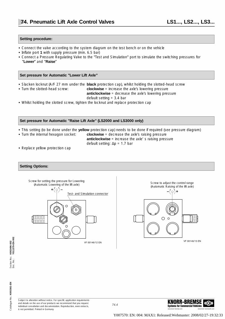
74. Pneumatic Lift Axle Control Valves LS1..., LS2..., LS3...
www.knorr-bremse.com www.knorr-bremsesfn.com
KNORR-BREMSESystems for Commercial Vehicles
Subject to alteration without notice. For specific application requirementsand details on the use of our products we recommend that you request individual consultation and documentation. Reproduction, even extracts,is not permitted. Printed in Germany
74.4
Sec
tion
No.
: K
0024
96-0
02D
oc. N
o.:
Y01
1379
-EN
-002
Cat
alog
ue N
o.: K
0015
61-E
N
Setting procedure:
• Connect the valve according to the system diagram on the test bench or on the vehicle• Inflate port 1 with supply pressure (min. 6.5 bar)• Connect a Pressure Regulating Valve to the "Test and Simulation" port to simulate the switching pressures for
"Lower” and "Raise”
Set pressure for Automatic "Lower Lift Axle”
• Slacken locknut (A/F 27 mm under the black protection cap), whilst holding the slotted-head screw• Turn the slotted-head screw: clockwise = increase the axle’s lowering pressure
anticlockwise = decrease the axle’s lowering pressuredefault setting = 3.4 bar
• Whilst holding the slotted screw, tighten the locknut and replace protection cap
Set pressure for Automatic "Raise Lift Axle” (LS2000 and LS3000 only)
• This setting (to be done under the yellow protection cap) needs to be done if required (see pressure diagram)• Turn the internal hexagon socket: clockwise = decrease the axle’s raising pressure
anticlockwise = increase the axle’ s raising pressuredefault setting: ∆p = 1.7 bar
• Replace yellow protection cap
Setting Options:
VF 00146/12 EN
+ –Test- and Simulation connector
Screw for setting the pressure for Lowering(Automatic Lowering of the lift axle)
VF 00146/13 EN
+–
Screw to adjust the control range(Automatic Raising of the lift axle)
Y007570: EN: 004: MAX1: Released:Webmaster: 2008/02/27-19:32:33

74. Pneumatic Lift Axle Control Valves LS1..., LS2..., LS3...
www.knorr-bremse.com www.knorr-bremsesfn.com
KNORR-BREMSESystems for Commercial Vehicles
Subject to alteration without notice. For specific application requirementsand details on the use of our products we recommend that you request individual consultation and documentation. Reproduction, even extracts,is not permitted. Printed in Germany
74.5
Sec
tion
No.
: K
0024
96-0
02D
oc. N
o.:
Y01
1379
-EN
-002
Cat
alog
ue N
o.: K
0015
61-E
N
7
6
5
4
3
2
1
0
Air
sprin
g pr
essu
re a
t sta
tic a
xle(
s) [b
ar]
poss
ible
adj
ustm
ent
rang
e fo
r"Lo
wer
"
upper Switching Point:= Automatic Lower of the lift axle(s), adjustable
Lower Switching Point I:maximum possible pressure, adjustable= automatic Raise of the lift axle(s)
Lower Switching Point II:lowest possible pressure, adjustable= automatic Raise of the lift axle(s)
Example:• upper switching point = "Lower" = 4,5 bar, set• lower switching point = "Raise" = adjustable from 1.75 to 3.0 bar
VF 00146/9 EN
Control pressure Diagram
Y007570: EN: 004: MAX1: Released:Webmaster: 2008/02/27-19:32:33

74. Pneumatic Lift Axle Control Valves LS1..., LS2..., LS3...
www.knorr-bremse.com www.knorr-bremsesfn.com
KNORR-BREMSESystems for Commercial Vehicles
Subject to alteration without notice. For specific application requirementsand details on the use of our products we recommend that you request individual consultation and documentation. Reproduction, even extracts,is not permitted. Printed in Germany
74.6
Sec
tion
No.
: K
0024
96-0
02D
oc. N
o.:
Y01
1379
-EN
-002
Cat
alog
ue N
o.: K
0015
61-E
N
Traction Assist:
The Traction Assist function allows temporary lifting of a laden axle on a semitrailer. This will result in an increase inload on the tractor’s drive axle and therefore improved traction.
The use of Traction Assist must adhere to any national legal requirements.
The control device in the tractor should be a spring return tip switch.
Traction Assist is achieved by upgrading LS2000 or LS3000.
• Additional component required:One Solenoid Valve LS2510 (ready for assemble)Please order separately!
Assembly:
• On LS2000 and LS3000 remove circlip holding the blanking plate (see arrow).
• Insert the Solenoid Valve LS2510 (with pre-assembled plate and circlip).
• Connect the control cable to the Solenoid Valve. The cable should then be securely attached to the chassis leadingto the point where it is to be connected to the tractor interface (normally via the 24S electrical trailer connection).
VF 00146/14 EN
Adjustment screw withyellow protection cap
23 or
2/3
Y007570: EN: 004: MAX1: Released:Webmaster: 2008/02/27-19:32:33

74. Pneumatic Lift Axle Control Valves LS1..., LS2..., LS3...
www.knorr-bremse.com www.knorr-bremsesfn.com
KNORR-BREMSESystems for Commercial Vehicles
Subject to alteration without notice. For specific application requirementsand details on the use of our products we recommend that you request individual consultation and documentation. Reproduction, even extracts,is not permitted. Printed in Germany
74.7
Sec
tion
No.
: K
0024
96-0
02D
oc. N
o.:
Y01
1379
-EN
-002
Cat
alog
ue N
o.: K
0015
61-E
N
Dimensions, with Solenoid Valve for Traction Assist
11 21 22 12 23
110
≈ 207
70
140
70
VF 00146/15
LS
200
0
3
KNORRBREMSE
Lowering the Lift Axle
When using the fully automatic valves, LS2000 or LS3000, the lift axle is always raised when the vehicle is unladen.However, there may be situations when the lift axle needs to be lowered when the vehicle is unladen.
For example:• When checking the brakes on a rolling road• When parking the vehicle• To reduce the turning radius (by reducing the effective wheelbase)
The required 3/2 Valves can be installed individually or in-line in the supply line to port 1 of the Lift Axle Control Valve.
12
Electricallyfrom thetractor
manually
PA
VF 00146/16 EN ÄI02
1
2
R
3
1
Examples:
AE4265 3/2 Valve with push button to lower lift axle manually0481007043 3/2 Valve with turning button to lower lift axle manually
AE9120 3/2 Valve with push button to lower lift axle electrically
Y007570: EN: 004: MAX1: Released:Webmaster: 2008/02/27-19:32:33

74. Pneumatic Lift Axle Control Valves LS1..., LS2..., LS3...
www.knorr-bremse.com www.knorr-bremsesfn.com
KNORR-BREMSESystems for Commercial Vehicles
Subject to alteration without notice. For specific application requirementsand details on the use of our products we recommend that you request individual consultation and documentation. Reproduction, even extracts,is not permitted. Printed in Germany
74.8
Sec
tion
No.
: K
0024
96-0
02D
oc. N
o.:
Y01
1379
-EN
-002
Cat
alog
ue N
o.: K
0015
61-E
N
System Diagram Example, dual circuit: 3-axle bogie without Raise / Lower Valve1 Lift Axle with fully automatic control
Y007570: EN: 004: MAX1: Released:Webmaster: 2008/02/27-19:32:33

74. Pneumatic Lift Axle Control Valves LS1..., LS2..., LS3...
www.knorr-bremse.com www.knorr-bremsesfn.com
KNORR-BREMSESystems for Commercial Vehicles
Subject to alteration without notice. For specific application requirementsand details on the use of our products we recommend that you request individual consultation and documentation. Reproduction, even extracts,is not permitted. Printed in Germany
74.9
Sec
tion
No.
: K
0024
96-0
02D
oc. N
o.:
Y01
1379
-EN
-002
Cat
alog
ue N
o.: K
0015
61-E
N
System Diagram Example, dual circuit: 3-axle bogie with Raise / Lower Valve1 Lift Axle with fully automatic control
Y007570: EN: 004: MAX1: Released:Webmaster: 2008/02/27-19:32:33

74. Pneumatic Lift Axle Control Valves LS1..., LS2..., LS3...
www.knorr-bremse.com www.knorr-bremsesfn.com
KNORR-BREMSESystems for Commercial Vehicles
Subject to alteration without notice. For specific application requirementsand details on the use of our products we recommend that you request individual consultation and documentation. Reproduction, even extracts,is not permitted. Printed in Germany
74.10
Sec
tion
No.
: K
0024
96-0
02D
oc. N
o.:
Y01
1379
-EN
-002
Cat
alog
ue N
o.: K
0015
61-E
N
System Diagram Example, single circuit: Air suspension System for 3 axle semi-trailerwith fully automatic Lift Axle control
Y007570: EN: 004: MAX1: Released:Webmaster: 2008/02/27-19:32:33

74. Pneumatic Lift Axle Control Valves LS1..., LS2..., LS3...
www.knorr-bremse.com www.knorr-bremsesfn.com
KNORR-BREMSESystems for Commercial Vehicles
Subject to alteration without notice. For specific application requirementsand details on the use of our products we recommend that you request individual consultation and documentation. Reproduction, even extracts,is not permitted. Printed in Germany
74.11
Sec
tion
No.
: K
0024
96-0
02D
oc. N
o.:
Y01
1379
-EN
-002
Cat
alog
ue N
o.: K
0015
61-E
N
System Diagram Example, single circuit: Air suspension System for 3 axle semi-trailerwith fully automatic Lift Axle control, with Raise / Lower Function
Y007570: EN: 004: MAX1: Released:Webmaster: 2008/02/27-19:32:33

75. Lift Axle Valves, pneumatically / manually controlled AE1124
www.knorr-bremse.com www.knorr-bremsesfn.com
KNORR-BREMSESystems for Commercial Vehicles
Subject to alteration without notice. For specific application requirementsand details on the use of our products we recommend that you request individual consultation and documentation. Reproduction, even extracts,is not permitted. Printed in Germany
75.1
Sec
tion
No.
: K
0024
97-0
00D
oc. N
o.:
Y01
1380
-EN
-000
Cat
alog
ue N
o.: K
0015
61-E
N
Function
The Lift Axle Valve is generally used in conjunction with a "full feedback”Charging Valve ( see page 77.1) on vehicles with air suspension to raise andlower a lift axle (see system diagram page 75.3).
When the vehicle is laden, pressure in the non-lift axle suspension systemexceeds the opening pressure of the Charging Valve and air flows to signal theLift Axle Valve. The lift axle bellows are then automatically exhausted and its airbags are connected to the non-lift axle suspension system.
When the vehicle is unladen, the lift axle can be manually raised by depressingthe push button and lowered by pulling it out again.
Technical Features
Maximum Operating Pressure: 8.5 barMaximum Temperature Range: -40 °C to +80 °CMedium: Compressed AirMaximum way through: Ø 6.0 mmApproximate Weight: 1.1 kg
Options
GrF 0032
Standard Symbol as DIN ISO 1219
21 22 23
1331211 4 AE1124
Type No. Air Port Threads
AE1124 M12x1,5 – 12
AE1124
Y007570: EN: 004: MAX1: Released:Webmaster: 2008/02/27-19:32:33

75. Lift Axle Valves, pneumatically / manually controlled AE1124
www.knorr-bremse.com www.knorr-bremsesfn.com
KNORR-BREMSESystems for Commercial Vehicles
Subject to alteration without notice. For specific application requirementsand details on the use of our products we recommend that you request individual consultation and documentation. Reproduction, even extracts,is not permitted. Printed in Germany
75.2
Sec
tion
No.
: K
0024
97-0
00D
oc. N
o.:
Y01
1380
-EN
-000
Cat
alog
ue N
o.: K
0015
61-E
N
Dimensions
3737
M8
14
63
ø37
7690
4920 22
52,5
29,5
22
12ø17
20
12
Stro
ke 1
4 m
m
29,5 29,5
52,552,5
23
4 13
363
14
On Installation,Exhaust mustpoint downwards
VF00075/12 EN
21
11
3
AE1124
Air Port Identification:
11 Right air supply from levelling velve / non-lift axle air bag(s)
12 Left air supply from levelling valve / non-lift axle air bag(s)
13 Air supply for lifting bellows from suspension reservoir
3 Exhaust
21 Right air delivery to lift axle air bag
22 Left air delivery to lift axle air bag
23 Air connection for lifting bellows
4 Signal from Charging Valve
Y007570: EN: 004: MAX1: Released:Webmaster: 2008/02/27-19:32:33

Cat
alog
ue N
o.: K
0015
61-E
NS
ectio
n N
o.:
K00
2497
-000
Doc
. No.
:Y
0113
80-E
N-0
00
www.knorr-bremse.com www.knorr-bremsesfn.com
KNORR-BREMSESystems for Commercial Vehicles
Subject to alteration without notice. For specific application requirementsand details on the use of our products we recommend that you request individual consultation and documentation. Reproduction, even extracts,is not permitted. Printed in Germany
75.3
75. Lift Axle Valves, pneumatically / manually controlled AE1124
Component Key:
6 Drain Valve7 Charging Valve8 Suspension Reservoir
15 Test Point33 Levelling Valve34 Suspension Air Bag38 Throttle Check Valve39 Damping Reservoir40 Charging Valve41 Lift Axle Valve42 Pressure Limiting Valve43 Quick Release Valve44 Axle Lifting Bellows
System Diagram: Example on a 3 Axle Semi-trailer
Y007570: EN: 004: MAX1: Released:Webmaster: 2008/02/27-19:32:33

76. Lift Axle Valves, electrically controlled AE1141
www.knorr-bremse.com www.knorr-bremsesfn.com
KNORR-BREMSESystems for Commercial Vehicles
Subject to alteration without notice. For specific application requirementsand details on the use of our products we recommend that you request individual consultation and documentation. Reproduction, even extracts,is not permitted. Printed in Germany
76.1
Sec
tion
No.
: K
0024
98-0
02D
oc. N
o.:
Y01
1381
-EN
-002
Cat
alog
ue N
o.: K
0015
61-E
N
VF 00199_303
Standard Symbol as DIN ISO 1219
11
21
AE1141 ÄI01
3
23
4
1
•
Dimensions
Function
The electrically controlled Lift Axle Valve is used for trailers withelectronic braking systems to control the lift axle(s) fully automaticallyaccording to the vehicle load.The load sensing and the electronic control functions are achieved by theEBS. Without electric power supply, the lift axle is lowered.
The lift axle can be lowered manually if the vehicle is unladen – e.g. with the3/2 Control Valve AE4265.(Note: This is not permissible if the EBS incorporates RSP! In this case the liftaxle is lowered by an electrical signal sent to the EBS; see page 40.2)The valve can also be used as a solenoid valve for other applications as liftaxle control. System diagram examples can be found an page 76.3.
Technical Features
Maximum Operating pressure.: 10 barOperating Temperature Range: -40 °C to +80 °C Nominal Voltage: 24
+8-6 V DC
Medium: Compressed Air Approximate Weight: 0,8 kg
Product Overview
Type No. Part No. Ports 1, 11, 21, 23 Port 3
AE1141 K008546 M16x1,5 Thread M16x1,5
System Diagramssee page 76.3
Y007570: EN: 004: MAX1: Released:Webmaster: 2008/02/27-19:32:33

76. Lift Axle Control Valves, electrically controlled AE1141
Subject to alteration without notice. For specific application requirements
and details on the use of our products we recommend that you request
individual consultation and documentation. Reproduction, even extracts,
is not permitted. Printed in Germany
76.2
Cata
logue N
o.: K
0015
61S
ection N
o.:
K00
2498
-000
Doc.
No.:
Y01
1381
-EN
-000
Pos. Name Type- /Part-No.: Quantity
1 Overflow Valve DR4378 1
2 In-Line Air Filter LA2103 1
3 Reservoir VB33.. -
4 Drain Valve EE1100 -
5 Levelling Valve with height limitation and secondary exhaust SV1466 1
6 Lift Axle Control Valve AE1141 1
7 Raise Lower Valve SV3240 1
8 Distributor Block LS5... 1
9 Operating Valve AE4265 1
10 Pressure Limiting Valve (optional) DB1116 1
11 Pressure Sustaining Valve (optional) LS1051 1
- Clamping band for Pos. 3; d=...mm VB1... -
- Rubber joint at the lower end for Pos 5 K001406 1
Air Suspension System for a 3 axle semitrailerwith raise/lower function, one fully automatic lift axle
controlled by TEBS (Trailer Electronic Braking System)
System Diagram
Y007570: EN: 004: MAX1: Released:Webmaster: 2008/02/27-19:32:33
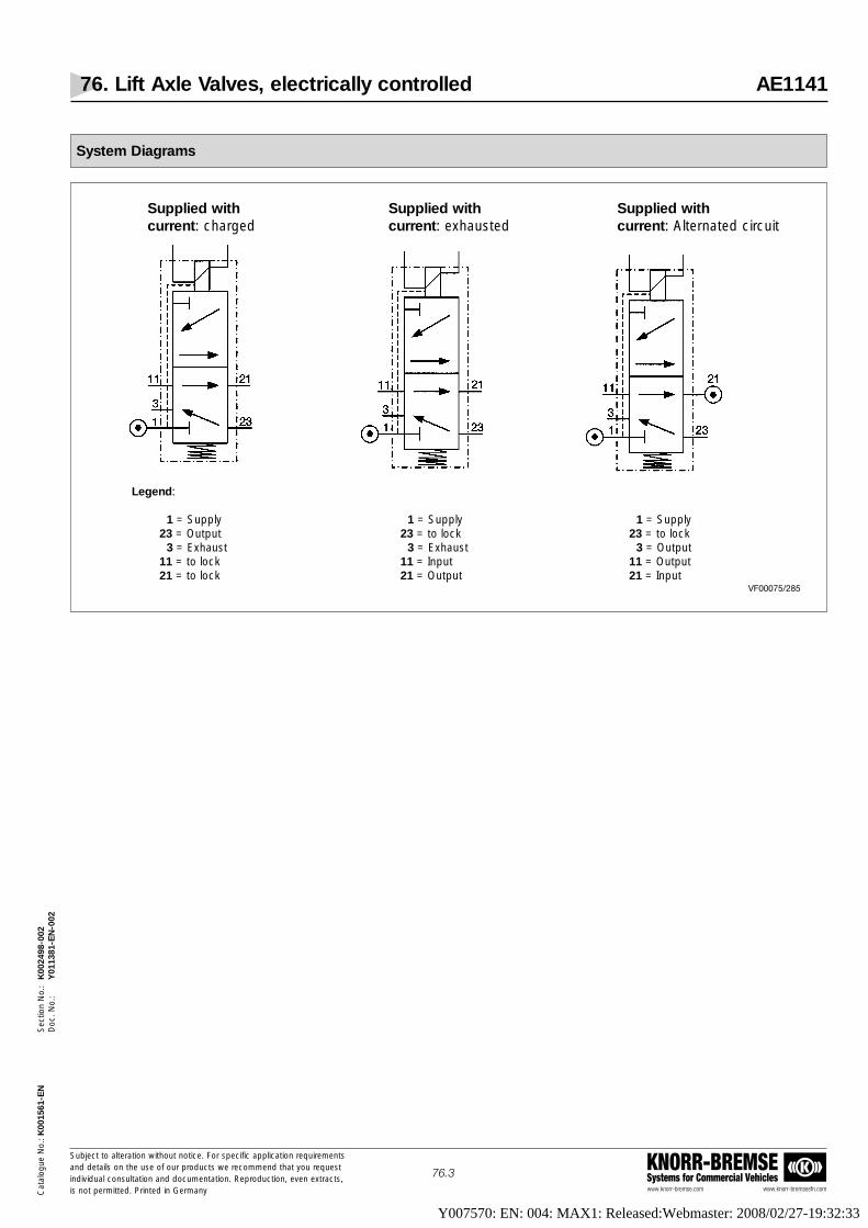
76. Lift Axle Valves, electrically controlled AE1141
www.knorr-bremse.com www.knorr-bremsesfn.com
KNORR-BREMSESystems for Commercial Vehicles
Subject to alteration without notice. For specific application requirementsand details on the use of our products we recommend that you request individual consultation and documentation. Reproduction, even extracts,is not permitted. Printed in Germany
76.3
Sec
tion
No.
: K
0024
98-0
02D
oc. N
o.:
Y01
1381
-EN
-002
Cat
alog
ue N
o.: K
0015
61-E
N
System Diagrams
VF00075/285
Supplied with Supplied with Supplied with current: charged current: exhausted current: Alternated circuit
Legend:
1 = Supply 1 = Supply 1 = Supply23 = Output 23 = to lock 23 = to lock
3 = Exhaust 3 = Exhaust 3 = Output11 = to lock 11 = Input 11 = Output21 = to lock 21 = Output 21 = Input
Y007570: EN: 004: MAX1: Released:Webmaster: 2008/02/27-19:32:33

77. Charging Valves DR4...
www.knorr-bremse.com www.knorr-bremsesfn.com
KNORR-BREMSESystems for Commercial Vehicles
Subject to alteration without notice. For specific application requirementsand details on the use of our products we recommend that you request individual consultation and documentation. Reproduction, even extracts,is not permitted. Printed in Germany
77.1
Sec
tion
No.
: K
0024
99-0
01D
oc. N
o.:
Y01
1382
-EN
-001
Cat
alog
ue N
o.: K
0015
61-E
N
Function
A Charging Valve is used where a protected air supply pressure or pressuresensitive signal is required.
Charging Valves are typically used to prevent suspension and auxiliary systemreservoirs being supplied before the brake system reservoirs are fully charged.
The valves have an adjustable opening pressure which stops air pressurebeing delivered from the valve until the desired pressure is reached.
Charging Valves with Feedback can be used to control the load-dependentlowering of the lifting axle if the Lift Axle Control Valve AE1124 is used (seepage 75.3)
Charging Valves without Feedback can be used in the supply to the airsuspension reservoirs to ensure priority is initially given to the service brakereservoirs.
Charging Valves fall into three main categories:
DR4150 has a full feedback function. Once the valve is open, air can flowunrestricted in both directions through the valve. If supply pressure drops,delivered pressure will feed back and this can continue until both supply anddelivery pressures are zero.
DR4256 has a Limited Feedback function. Once the valve is open, air canflow unrestricted in both directions through the valve. However if the supplypressure drops, at a preset pressure the valve will close and the downstreampressure will no longer feed back irrespective of any further reduction in thesupply pressure.
DR43.. valves have a Non-Feedback function. Once the valve is open, air canflow through the valve to increase the downstream pressure. However, if thesupply pressure drops, a non-return valve prevents the return flow of air underall conditions.
Technical Features
Maximum Service Pressure: 20 barOperating Temperature Range: -40 °C to +80 °CWay Through: Ø 8 mmMedium: Compressed AirApproximate Weight: 0.2 kg
VF00199_167
Standard Symbol as DIN ISO 1219
DR4150
DR4256
DR4370DR4378
2
DR 4125
2
DR 4232
2
DR 4341
Y007570: EN: 004: MAX1: Released:Webmaster: 2008/02/27-19:32:33

Cat
alog
ue N
o.: K
0015
61-E
NS
ectio
n N
o.:
K00
2499
-001
Doc
. No.
:Y
0113
82-E
N-0
01
www.knorr-bremse.com www.knorr-bremsesfn.com
KNORR-BREMSESystems for Commercial Vehicles
Subject to alteration without notice. For specific application requirementsand details on the use of our products we recommend that you request individual consultation and documentation. Reproduction, even extracts,is not permitted. Printed in Germany
77.2
77. Charging Valves DR4...
~ 81
~98
82
SW 30
57
68
VF 00075/58 EN
Air passage indirection of the arrow
1 2
DR4125DR4232DR4341DR4350
Dimensions
DR4150DR4256DR4370DR4378
DR4125DR4232DR4341DR4350
Type No. Opening Closing Feedback Air Port Replaces:Pressure [bar] Pressure [bar] Threads
DR4150 1) – Yes DR4125
DR4256 6,0 5,4 LimitedM22x1,5-14
DR4232
DR4370 1) – No DR4350
DR4378 6,0 5,4 No DR4341
Options
Other versions can be delivered on request!
1) Setting Range 1 to 10 bar. After setting, mark the opening pressure on plate.
Y007570: EN: 004: MAX1: Released:Webmaster: 2008/02/27-19:32:33

78. 3/2 Control Valves AE4265, AE4266
www.knorr-bremse.com www.knorr-bremsesfn.com
KNORR-BREMSESystems for Commercial Vehicles
Subject to alteration without notice. For specific application requirementsand details on the use of our products we recommend that you request individual consultation and documentation. Reproduction, even extracts,is not permitted. Printed in Germany
78.1
Sec
tion
No.
: K
0025
00-0
00D
oc. N
o.:
Y01
1383
-EN
-000
Cat
alog
ue N
o.: K
0015
61-E
N
Function
These Control Valves are used for auxiliary systems on trailers. By depressingthe button port 2 is pressurised, by pulling the button out port 2 is exhausted.
The valve exists in two versions that differ in the colour of the button only. Thevalve with the green button is typically used to lower lift axles on unladen vehicles (see page 74.6), the one with the white button is used for auxiliary functions that are not related to lift axle control (e.g. operating working cylinders). Both valves have detents in the end positions.
Technical Features
Maximum Operating Pressure: 8.5 barOperating Temperature Range: -40 °C to +80 °CWay Through: 4.5 mmMedium: Compressed AirApproximate Weight: 0.4 kg
Options
Type No. Air Port Threads Installation B u t t o nColour Shape
AE4265M16x1,5 Auxiliary System
Green Round, without
AE4266 White symbol plate
VF00199_170
Standard Symbol as DIN ISO 1219
2
123/11 AE 4262
Y007570: EN: 004: MAX1: Released:Webmaster: 2008/02/27-19:32:33

78. 3/2 Control Valves AE4265, AE4266
www.knorr-bremse.com www.knorr-bremsesfn.com
KNORR-BREMSESystems for Commercial Vehicles
Subject to alteration without notice. For specific application requirementsand details on the use of our products we recommend that you request individual consultation and documentation. Reproduction, even extracts,is not permitted. Printed in Germany
78.2
Sec
tion
No.
: K
0025
00-0
00D
oc. N
o.:
Y01
1383
-EN
-000
Cat
alog
ue N
o.: K
0015
61-E
N
Dimensions
AE4265AE4266
Y007570: EN: 004: MAX1: Released:Webmaster: 2008/02/27-19:32:33

79. Throttle Check Valves SEB00778
www.knorr-bremse.com www.knorr-bremsesfn.com
KNORR-BREMSESystems for Commercial Vehicles
Subject to alteration without notice. For specific application requirementsand details on the use of our products we recommend that you request individual consultation and documentation. Reproduction, even extracts,is not permitted. Printed in Germany
79.1
Sec
tion
No.
: K
0025
01-0
01D
oc. N
o.:
Y01
1384
-EN
-001
Cat
alog
ue N
o.: K
0015
61-E
N
Function
The Throttle Check Valve is used in air systems to control the rate of air flow inone direction.
The Valve can be used in combination with a small reservoir prior to theCharging Valve in the control line of the Axle Lifting Valve AE1124 (see page75.3).
The Throttle Check Valve and Reservoir act to dampen any pressure variations(caused by cornering or rough road surface) in the non-lift axle suspensionsystems that can otherwise cause the lift axle of a semi-laden trailer to lower.
As the load imposed on the non-lift axle suspension is reduced, air pressurefrom the damping reservoir can flow un-throttled back into the suspensionsystem.
The valve is supplied complete with pre-installed "push-in" fittings.
Technical Features
Maximum Operating Pressure: 10 barOperating Temperature Range: -40 ºC to +80 ºCMaximum Way Through: Ø 2,5 mmMedium: Compressed AirApprox. Weight: 0,05 kg
Options
GrF 0011
Standard Symbol as DIN ISO 1219
SEB 00778
Type No. Fitting for Pipe Diameter "D"
– 8mm
Dimensions
26
60,5
SW 11
44
20 ø D
Plug-in Connection for polyamide, PU and Flexo-55 pipes
Flow Direction
Arrow
18,5
12,5
Setting Screw
ø 3,2
VF 00075/59 EN
SEB00778
Y007570: EN: 004: MAX1: Released:Webmaster: 2008/02/27-19:32:33

80. Manifold Block LS55..
www.knorr-bremse.com www.knorr-bremsesfn.com
KNORR-BREMSESystems for Commercial Vehicles
Subject to alteration without notice. For specific application requirementsand details on the use of our products we recommend that you request individual consultation and documentation. Reproduction, even extracts,is not permitted. Printed in Germany
80.1
Sec
tion
No.
: K
0025
02-0
01D
oc. N
o.:
Y01
1385
-EN
-001
Cat
alog
ue N
o.: K
0015
61-E
N
Function
The Manifold Block is used for single circuit air suspension systems on semi-trailers or centre axle trailers.It is used for connecting the air suspension bags to the Raise / Lower Valveand the Lift Axle Control Valve (optional). The Manifold Block is delivered with push-in fittings saving the manufacturer asignificant number of connectors and installation time.
(See also position 18 of the system drawing with EBS in the content chapter).
LS5500 is normally used on 3 axle semi-trailers without lift axle and LS5501 on 3 axle semi-trailers with one lift axle.
Technical Features
Maximum Operating Pressure: 10 barOperating Temperature Range: -40 °C to +60 °CMedium: Compressed AirApproximate Weight: 0,5 kgSurface: Elox
Product Overview
VF00199_276
Standard Symbol as DIN ISO 1219
LS5000
23
2527
221
242628
Type No. Supply Connection Delivery Connections(push-in fittings) (push-in fittings)
LS5500 1 connector 12 x 1,5 7 connectors 8 x 1
LS5501 1 connector 12 x 1,5 6 connectors 8 x 1
Dimensions
VF00075/220 EN ÄI01
LS5500LS5501
57,5
Ø35
2x M616 deep
40
only with LS5500
12,5
27,5
45,5
1x plug connection12x1,5
6x or 7x plug connection8x1 (see "Product Overview")
18
= =
18
= =
LS5001
23
2527
221
2426
LS5500
LS5501
Y007570: EN: 004: MAX1: Released:Webmaster: 2008/02/27-19:32:33

Cat
alog
ue N
o.: K
0015
61-E
N-0
01S
ectio
n N
o.:
K00
2503
-000
Doc
. No.
:Y
0113
86-E
N-0
00
www.knorr-bremse.com www.knorr-bremsesfn.com
KNORR-BREMSESystems for Commercial Vehicles
Subject to alteration without notice. For specific application requirementsand details on the use of our products we recommend that you request individual consultation and documentation. Reproduction, even extracts,is not permitted. Printed in Germany
90.1
90. Data Sheet for Brake Calculation
Trailer Manufacturer:
Trailer Type:
With TEBS Number of teeth of the Desired ABS configuration: 2S/2M 4S/2M 4S/3M
With ABS pole wheel:
Without ABS vmax. [km/h]:
With Trailer Information Module (TIM)
Unladen Laden Actuator Type Size / Number
Total Weight P kg
Load at Axle 1 P1 kg
Load at Axle 2 P2 kg
Load at Axle 3 P3 kg
Load at Axle 4 P4 kg
Height of Centre of Gravity h mm
For all trailers:
Wheelbase:
E1 [mm]: E2 [mm]: E3 [mm]: E4 [mm]:
Tyre Size or Dynamic Tyre Radius:
Possible lever length:
Spring brake parking: Yes No
Lifting axle: Axle 1 Axle 2 Axle 3
Suspension: Air suspension Mechanical suspension
Spring deflection (mechanical suspension): (unladen : laden) [mm]:
Trailing steer axle: Yes No
Suspension type: Balanced (non-reactive) Not balanced (reactive)
Axle Manufacturer: Axle Type:
Brake Size: Test Report No.:
To help Knorr-Bremse complete your brake calculation quickly and efficiently, please complete all sections of the Data Sheet!
If the trailer is not easy to describe, please provide additional data (sketches)!Reprodution is not permitted! Status: 01.2003
Centre Axle Trailer Semi-TrailerDrawbar Trailer
PP
E1 E2 E3
P1, P2, P3
h h
P2, P3P1, (P4) P
CofG CofG CofG
h
E3E1
E2E1
E2 E3
P1, P2, P3
VF00075/211 EN
E4
Y007570: EN: 004: MAX1: Released:Webmaster: 2008/02/27-19:32:33

Cat
alog
ue N
o.: K
0015
61-E
N-0
01S
ectio
n N
o.:
K00
2503
-000
Doc
. No.
:Y
0113
86-E
N-0
00
www.knorr-bremse.com www.knorr-bremsesfn.com
KNORR-BREMSESystems for Commercial Vehicles
Subject to alteration without notice. For specific application requirementsand details on the use of our products we recommend that you request individual consultation and documentation. Reproduction, even extracts,is not permitted. Printed in Germany
90.2
90. Data Sheet for Brake Calculation and Air Suspension
Trailer Manufacturer:
Trailer Type:
Characteristics:
RSP: Yes No
Main power supply via Stop Light: Yes No
Combined Park / Shunt Valve: Yes No
Separate Release Valve for the front axle: Yes No
Air Suspension characteristic:
Air Suspension manufacturer Air Spring Bellow Suspension arm lengths: Bellows pressure:
and Type No.: diameter: L1 = unladen =
L2 = laden =
Design of the air suspension: Single circuit Dual circuit
Air suspension with limitation of height: Yes No
With lifting and lowering: Yes No
with Reset to Ride: Yes No
if no, with automatic return to STOP position: Yes No
Bilateral separated lowering: Yes No
Trailer with lifting axle control: Yes No
if yes, please mark the position in the drawing
Design of the lifting axle control: Via TEBS Conventional
if conventional: Fully automatic Semi-automatic
Traction help: Yes No
Forced lowering of the lifting axle: Yes No
if yes, design: Electrically Manually Both
Rapid bleed of the bellows: Yes No
Adjustment of the zero point (2nd ride height): Yes No
If the trailer is not easy to describe, please provide additional data (sketches)!Reprodution is not permitted! Status: 01.2003
Centre Axle Trailer Semi-TrailerDrawbar Trailer
VF00075/212 EN
Lifting axle ? Lifting axle ?Lifting axle ?
Y007570: EN: 004: MAX1: Released:Webmaster: 2008/02/27-19:32:33
Brake and Air Suspension Products
for Trailers
Bra
ke a
nd
Air
Su
spen
sio
n P
rod
uct
sfo
r T
rail
ers P r o d u c t C a t a l o g u e
Knorr-BremseSysteme für Nutzfahrzeuge GmbHMoosacher Straße 8080809 MunichGermanyTel: +49 89 3547-0Fax: +49 89 3547-2767
Knorr-BremseAustralia Pty. Ltd.1/2D Factory StreetPO Box 180Granville NSW 2142AustraliaTel: +61 1300 309-991Fax: +61 2 8863-6151
Knorr-Bremse GmbHSysteme für NutzfahrzeugeBeethovengasse 43-452340 MödlingAustriaTel: +43 2236 409-436Fax: +43 2236 409-434
Knorr-BremseBenelux B.V.B.A.Impulsstraat 11Industriepark zone D2220 Heist-op-den-BergBelgiumTel: +32 1525 7900Fax: +32 1524 9240
Knorr-BremseSistemas para Veículos Comerciais Brasil Ltda.Av. Engenheiro Eusébio Stevaux, 873JurubatubaSão Paulo – SPCep: 04696-902BrazilTel: +55 11 5681 1104Fax: +55 11 5686 3905
Knorr-Bremse Far East Ltd.Truck Brake Systems DivisionSuite 2901, 29/F., Central Plaza18 Harbour RoadWanchaiHong KongChinaTel: +852 2861 2669Fax: +852 2520 6259
Knorr-Bremse Brake Equipment (Shanghai) Co. Ltd.Truck Brake Systems DivisionSection A, Building 31390 Aidu RoadWaigaoqiao Free Trade ZoneShanghai, 200131ChinaTel: +86 21 5046-0776Fax: +86 21 5046-3427
Knorr-BremseSystémy pro uz̆itková vozidla, C̆R, s.r.o.Petra Bezruc̆e 399463 62 HejniceCzech RepublicTel: +420 482 363-611Fax: +420 482 363-711
Knorr-BremseSystèmes pour Véhicules Utilitaires France S.A.BP 34178RN 13, La BriqueterieGlos14104 Lisieux CedexFranceTel: +33 2 3132 1200Fax: +33 2 3132 1303
Hasse & Wrede GmbHGeorg-Knorr-Straße 412681 BerlinGermanyTel: +49 30 9392-3101Fax: +49 30 7009-0811
Knorr-BremseFékrendszerek Kft.KecskemétSzegedi út 496000HungaryTel: +36 76 511 100Fax: +36 76 481 100
Knorr-BremseSystems for Commercial Vehicles India Private Ltd.Survey No 280 & 281,Hinjawadi Phase II,Village Mann,Taluka Mulshi,Pune 411 057IndiaTel: +91 20 2293 9141-47Fax: +91 20 2293 9148
Knorr-BremseSistemi per Autoveicoli Commerciali S.p.A.Via Alessandro Polini, 15820043 ArcoreItalyTel: +39 039 6075-1Fax: +39 039 6075-435
Knorr-Bremse Commercial Vehicle Systems Japan Ltd.3-1-15, NishiikebukuroToshima-kuTokyo 171 0021JapanTel: +81 3 3971-8501Fax: +81 3 3971-8579
Knorr-Bremse Korea Ltd.Truck Brake Division6 FL, Bongwoo B/D, 31-7, 1-GaJangchung-Dong, Jung-GuSeoul 100-391KoreaTel: +82 2 2273-1182Fax: +82 2 2273-1184
Knorr-BremseBenelux B.V.B.A.Rendementsweg 4N3641 SK MydrechtNetherlandsTel: +31 297 239-330Fax: +31 297 239-339
Knorr-Bremse RUSPamirskaja Str. 11603029 Nischnij NovgorodRussian FederationTel: +7 Fax: +7
Knorr-BremseSysteme für Nutzfahrzeuge GmbHRepresentation Office Russia1. Kasatschij Pereulok 5/2119017 MoscowRussian FederationTel: +7 095 234-4995Fax: +7 095 234-4996
Knorr-Bremse S.A. Pty. Ltd.3 Derrick Road(corner Chestnut Road)1610 Kempton ParkSouth AfricaTel: +27 11 961-7800Fax: +27 11 975-8249
Bost Ibérica, S.L.Avda. Letxunborro 58Apdo. 36320303 IrunSpainTel: +34 902 100 569Fax: +34 943 614 063
Knorr-BremseSystem for Tunga Fordon ABP.O. Box 6029200 11 MalmoeSwedenTel: +46 40 680 5880Fax: +46 40 937490
Knorr-BremseSysteme für Nutzfahrzeuge GmbHOffice SwitzerlandZürichstraße 468303 BassersdorfSwitzerlandTel: +41 1 888 77-55Fax: +41 1 888 77-50
Knorr-BremseSysteme für Nutzfahrzeuge GmbHLiaison Office IstanbulMeclisi Mebusan Cad. 139/AAtlantik Han Kat: 380040 Findikli - IstanbulTurkeyTel: +90 212 293-4742Fax: +90 212 293-4743
Knorr-BremseSystems for Commercial Vehicles Ltd.Century House, Folly Brook RoadEmerald Park, Emersons GreenBristolBS16 7FEUnited KingdomTel: +44 117 9846-100Fax: +44 117 9846-101
Bendix Commercial Vehicle Systems LLC901 Cleveland StreetElyria, OH 44035USATel: +1 440 329-9100Fax: +1 440 329-9105
K001
561-
EN-0
2 08
.200
5
The f
igur
ative
mar
k ”K”
and
the t
rade
mar
ks K
NORR
, KNO
RR-B
REM
SE ar
e reg
ister
ed in
the n
ame o
f Kno
rr-Br
emse
AG.
Subj
ect t
o alte
ratio
n w
ithou
t not
ice. F
or sp
ecifi
c app
licat
ion
requ
irem
ents
and
deta
ils on
the u
se of
our p
rodu
cts w
e rec
omm
end
that
you
requ
est i
ndivi
dual
cons
ulta
tion
and
docu
men
tatio
n. Th
is do
cum
ent,
eithe
r in
part
or w
hole,
may
not
be c
opied
, rep
rodu
ced
or tr
ansm
itted
in an
y for
m w
ithou
t the
prio
r exp
licit
perm
issio
n of
Kno
rr-Br
emse
Syste
me f
ür N
utzfa
hrze
uge G
mbH
. An
y con
trave
ntio
n w
ill b
e liab
le fo
r dam
ages
and
pros
ecut
ion.
The c
onte
nts o
f thi
s doc
umen
t are
also
pro
tect
ed u
nder
EU re
gulat
ion
6/20
02 an
d eq
uiva
lent l
ocal
legisl
atio
n. A
ll rig
hts r
eser
ved.
Prin
ted
in G
erm
any.
06.
2005
Y007570: EN: 004: MAX1: Released:Webmaster: 2008/02/27-19:32:33


