[email protected] Firestone ESADE Idiomas CALL&EPC September 27th 2001.


2
Table of Contents and Introduction...............................2Advantages of Airstroke Actuators ...............................3Advantages of Airmount Isolators.................................4Air Spring Bellows Construction ...................................5End Closure OptionsCrimped bead plates..................................................6Crimped bead plates mounting hardware .................7Steel bead rings.........................................................8Aluminum bead rings.................................................9The three types of bead rings andmounting hardware................................................10Rolled plates ............................................................11
How to use the Static Data ChartFor Airstroke Actuation......................................12&13For Airmount Isolation..............................................13
Internal Rubber Bumpers..............................................13Basic Parameters Applicable to Both AirstrokeActuators and Airmount IsolatorsMedia .......................................................................14Pressure ..................................................................14Temperature ...........................................................14Contaminants...........................................................14Storage ....................................................................14
Airstroke ActuationSelection ..................................................................15Down and Up Stops.................................................15Return ......................................................................15Guiding ....................................................................15Angular Capability....................................................15Horizontal Misalignment ..........................................16Design Envelope......................................................16Stacking ...................................................................16Fail-Safe Devices.....................................................16Vacuum....................................................................16Inflation Pressure Chart ...........................................17Airstroke Actuator Problem Solvers ...........18,19 & 20
Airmount Vibration IsolationSelection Procedure and Isolation Formula .......21-22Dynamic Spring Rate Formula ................................22Natural Frequency Formula.....................................22Center of Gravity......................................................23Lateral Rates and Stability.......................................23Triple Convoluted and ReversibleSleeve Type Parts .................................................24Design Envelope......................................................24Safety Stops ............................................................24Initial Installation ......................................................24Startup and Shutdown/Resonanceand Amplification ...................................................24Isolating an Unbalanced Mass ................................24Low Pressure Operation..........................................24Effect of an Auxiliary Reservoir ...............................24Damping ..................................................................25Plumbing Systems...................................................25Isolation Chart..........................................................26Airmount Isolation Problem Solvers ...................27-28
Miscellaneous ApplicationsShock Impact Isolation.............................................29Protective Boot and Flexible Connector ..................29Vacuum Pump .........................................................29Inflatable Chuck .......................................................29Cam Follower...........................................................29Miscellaneous Problem Solvers .........................30-31
Airstroke/Airmount Selection Guide ......................32-33Individual Air Spring Data Pages..........................34-100Airomatic Polyactuator................................................101Index &Work SheetsOrder Number to Style Numberto Page Number .........................................102-103Airstroke Design Parameter Worksheet ............105
Airmount Design Parameter Worksheet................107Style Number to Page Number..............................109
TABLEOFCONTENTS
Firestone developed the air spring in the late 1930’s as amore efficient spring (vibration isolator) for use in vehiclesuspensions. Airide™ springs, as they were named, provid-ed the means for a suspension to reduce the amount ofroad shock and vibration transmitted into the vehicle.Millions of miles of actual use have proven the dependabili-ty and effectiveness of the air suspension concept usingAiride™ springs by Firestone.Airstroke™ actuators, Airmount™ isolators, and Airide™springs are Firestone registered trademark names for oneproduct: the air spring. The use of the air spring (actuator,industrial isolator and vehicular isolator, respectively) deter-mines which name is applied to it. All of the parts in thiscatalogue may be used as Airstroke actuators (except the1X84D-1 and 2M1A) or Airmount isolators, with two excep-tions: Triple convoluted and reversible sleeve type airsprings (except the 1M1A-0) should not be used asAirmount isolators without consulting Firestone.
Individual Airstroke actuators and Airmount isolators arecapable of generating a force or supporting a load of up to100,000 pounds, and a stroke capability of up to 14 inchesis possible. Included in this engineering manual aredetailed operating characteristics for many of the standardFirestone air springs, along with technical details and pro-cedures for using these products.
PLEASENOTE:The information contained in this publication is intended to provide a gen-eral guide to the characteristics and applications of these products. Thematerial, herein, was developed through engineering design and develop-ment, testing and actual applications and is believed to be reliable andaccurate. Firestone, however, makes no warranty, expressed or implied,of this information. Anyone making use of this material does so at his ownrisk and assumes all liability resulting from such use. It is suggested thatcompetent professional assistance be employed for specific applications.
Copyright © 2007 BFS Diversified Products, LLC
INTRODUCTION


3
ADVANTAGESOFFIRESTONEAIRSTROKE™ ACTUATORS
Why use an Airstroke actuator (rather than air or hydraulic cylinder)for actuation?LOWCOSTGenerally, initial cost is one-half or less than conventional pneumatic or hydraulic cylin-ders of the same force capabilities. This initial cost advantage is many times greater inthe larger sizes.
WIDESIZERANGEAirstroke actuators are available in sizes ranging from 2.2 inches to 37 inches in diameter.The force capability is 100,000 pounds. Strokes of up to 14 inches are possible.
DURABLEFORLONGLIFEAirstroke actuators are a further application of Firestone’s time proven Airide springs fortruck and bus suspensions. The long life and durability necessary for millions of miles ofheavy duty suspension use under adverse environmental conditions are also importantfactors in machine design.
NOMAINTENANCEORLUBRICATIONREQUIREDNO INTERNALRODORPISTONAirstroke actuators have no internal rod, piston, or sliding seals as do conventionalcylinders. This allows for the design of Airstroke actuators into applications where dirt orgrit would destroy the seals on conventional cylinders.
FRICTIONFREEFOR IMMEDIATERESPONSESince Airstroke actuators have no sliding seals, there is no breakaway friction as withconventional cylinders
FLEXIBLEMEDIAAn Airstroke actuator can do its work with either a liquid or gas (Please see page 14 foracceptable media choices.)
ANGULARCAPABILITYAn Airstroke possesses the unique capability of stroking through an arc without a clevis.Angular motion of up to 30 degrees is possible, along with the design advantage ofgenerally less complex linkages.
SIDE LOADINGCAPABILITYAirstroke actuators, within certain limits, are notaffected by side loads as are conventional cylin-ders. This misalignment capability eliminatespotential rod bending, scoring, and excessive sealwear common to conventional cylinders.
COMPACTSTARTINGHEIGHTAirstroke actuators have a low profile compared toconventional cylinders. Our smallest Airstrokeactuator (2.2 inch/dia.) collapses to just 1.1 inchesin height, while our largest triple convolutedAirstroke (37 inch/dia.) will collapse to a very com-pact 5.5 inches.
FACTORYSEALEDANDTESTEDMost Airstroke actuators feature Firestone’s provenconcept of crimped end plates. The crimped designallows for preshipment testing and quicker installa-tion on equipment.PLEASEREFER TOPAGE 15 FORA THOROUGHDISCUSSIONOFACTUATION.

4
Why use an Airmount isolator rather than a coilspring or other type of isolator?UNSURPASSED ISOLATIONCAPABILITYAirmount isolators can provide the highest degree of isolationof any type vibration isolator. System natural frequencies aslow as 60 cycles per minute (1 Hertz) are available. Theaddition of an auxiliary reservoir can provide even lower sys-tem frequencies. In order to achieve similar results from aconventional coil spring isolator, a real deflection of 9 incheswould be required.
CONSTANT ISOLATIONEFFICIENCYAirmount isolators are unique in that the system’s natural fre-quency does not change significantly with changes in load.This unique feature, combined with accurate height control, willallow the use of the same Airmount isolator at each mountingpoint of an unevenly loaded machine.
ACCURATEHEIGHTCONTROLAirmount isolators provide accurate height control through reg-ulation of internal air pressure. This feature eliminates thefatigue and permanent set found in the use of other types ofvibration isolators.
WIDESIZERANGEAirmount isolators are capable of isolating loads of 100pounds per mounting point to over 100,000 pounds permounting point.
COMPACT INSTALLEDHEIGHTAirmount isolators can carry the loads and provide the isolationdescribed above at installed heights as low as 2.5 inches. Coilsprings providing equal isolation would require a free height of5 to 25 inches.
EXTENDEDEQUIPMENTLIFEAirmount isolators extend equipment life through their superiorisolation capabilities.
EFFECTIVENOISEREDUCTIONAirmount isolators reduce structurally transmitted noise.Airmount isolators are also quiet in themselves, since there isno spring chatter as found in conventional coil springs.
VERSATILEAirmount isolators can be used not only to protect structuralmembers from vibrating machinery, but are also widely usedto protect delicate equipment from structurally transmittedvibration.PLEASE REFER TO PAGE 21 FOR A THOROUGHDISCUSSION OF VlBRATION ISOLATION.
ADVANTAGESOFFIRESTONEAIRMOUNT™ ISOLATORS

5
An air spring is a carefully designed rubber/fabric bellowswhich contains a column of compressed air. The rubber bel-lows itself does not provide force or support load. This is doneby the column of air.Firestone air springs are highly engineered elastomeric bel-lows with specially designed metal end closures. Our standardtwo ply air spring bellows is actually made up of four layers:a. An inner liner of calendered rubber.b.One ply of fabric reinforced rubber.c. A second ply of fabric-reinforced rubber (with the cords ata specific bias angle to the first ply).
d. An outer cover of calendered rubber.Many of our air springs are also available in high strength con-struction for higher pressures (see page 14 for more detailedinformation). In this case, there are four plies of fabric-rein-forced rubber, with an inner liner and outer cover.
The two ply air spring is standard. Where high strength con-struction is available, it is so noted in the selection guide(page 32), on the individual Data sheets, and in the index(page 107). If the high strength style number is omitted, thenit is not currently available in that particular part.Each air spring bellows is identified by a style number. Thisstyle number is molded into the bellows during the curing (orvulcanization) process. Examples would be 16, 22, 313,1T15M-6, etc... This identifies only the rubber/fabric bellowsand not the complete assembly. There are several differentend closure options available for most air springs; therefore,please always specify both the style number and the completeassembly order number (AON). An example would be: Style#22, assembly order number W01-M58-6180. Both numbersare given on the individual data sheets.
OUTER COVER
SECOND PLY
FIRST PLY
INNER LINER
AIRSPRINGBELLOWSCONSTRUCTION
6
ENDCLOSUREOPTIONS
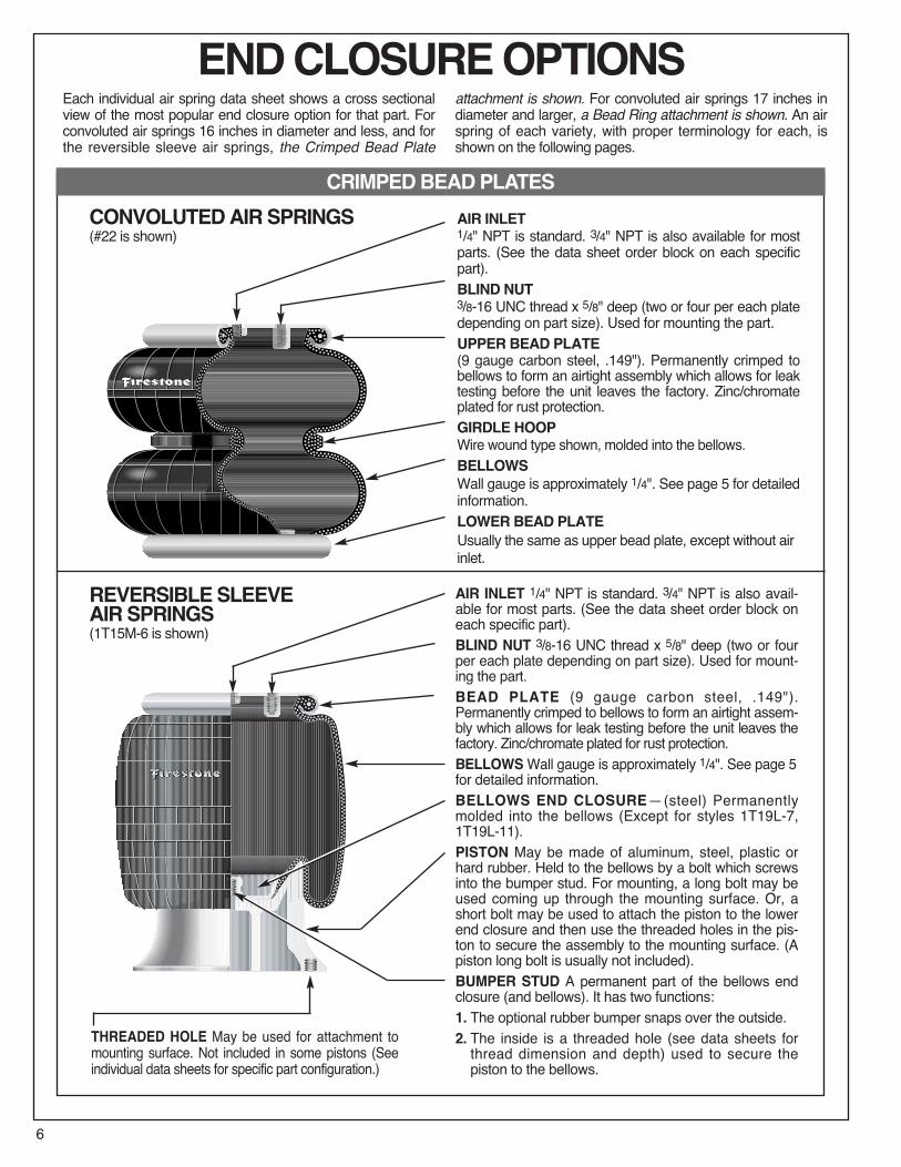
AIR INLET1/4" NPT is standard. 3/4" NPT is also available for mostparts. (See the data sheet order block on each specificpart).BLIND NUT3/8-16 UNC thread x 5/8" deep (two or four per each platedepending on part size). Used for mounting the part.UPPER BEAD PLATE(9 gauge carbon steel, .149"). Permanently crimped tobellows to form an airtight assembly which allows for leaktesting before the unit leaves the factory. Zinc/chromateplated for rust protection.GIRDLE HOOPWire wound type shown, molded into the bellows.BELLOWSWall gauge is approximately 1/4". See page 5 for detailedinformation.LOWER BEAD PLATEUsually the same as upper bead plate, except without airinlet.
Each individual air spring data sheet shows a cross sectionalview of the most popular end closure option for that part. Forconvoluted air springs 16 inches in diameter and less, and forthe reversible sleeve air springs, the Crimped Bead Plate
attachment is shown. For convoluted air springs 17 inches indiameter and larger, a Bead Ring attachment is shown. An airspring of each variety, with proper terminology for each, isshown on the following pages.
CONVOLUTEDAIRSPRINGS(#22 is shown)
REVERSIBLESLEEVEAIRSPRINGS(1T15M-6 is shown)
AIR INLET 1/4" NPT is standard. 3/4" NPT is also avail-able for most parts. (See the data sheet order block oneach specific part).BLIND NUT 3/8-16 UNC thread x 5/8" deep (two or fourper each plate depending on part size). Used for mount-ing the part.BEAD PLATE (9 gauge carbon steel, .149").Permanently crimped to bellows to form an airtight assem-bly which allows for leak testing before the unit leaves thefactory. Zinc/chromate plated for rust protection.BELLOWSWall gauge is approximately 1/4". See page 5for detailed information.BELLOWS END CLOSURE—(steel) Permanentlymolded into the bellows (Except for styles 1T19L-7,1T19L-11).PISTON May be made of aluminum, steel, plastic orhard rubber. Held to the bellows by a bolt which screwsinto the bumper stud. For mounting, a long bolt may beused coming up through the mounting surface. Or, ashort bolt may be used to attach the piston to the lowerend closure and then use the threaded holes in the pis-ton to secure the assembly to the mounting surface. (Apiston long bolt is usually not included).BUMPER STUD A permanent part of the bellows endclosure (and bellows). It has two functions:1. The optional rubber bumper snaps over the outside.2. The inside is a threaded hole (see data sheets forthread dimension and depth) used to secure thepiston to the bellows.
THREADED HOLE May be used for attachment tomounting surface. Not included in some pistons (Seeindividual data sheets for specific part configuration.)
CRIMPEDBEADPLATES

7
TANK VALVE One method for inflating air springs(primarily used in Airmount isolator applications) is witha tank valve: An air hose chuck is used (as inflating a
tire with an air line). Care must be taken to periodicallycheck the pressure within the air spring, because airwill slowly permeate through the rubber/fabric bellows(See page 25).
CRIMPEDBEADPLATEMOUNTINGHARDWARE
CRIMPED BEAD PLATE AIR SPRINGS Use the blindnuts for attachment. This is accomplished by bringing bolts(two or four depending upon air spring size) through the
customer supplied mountIng plate and tightening into theblind nut. If this bolt is too long, it may fracture the bottomout of the blind nut.
3/8-16 UNCBlind Nut,5/8" Deep
5/8"5/8"
To Air Supply
Customer SuppliesMounting PlatesBolts & Washers
Customer SuppliesMounting PlatesNuts & Washers
Tightening Torqueon the blind nut: 15 to 20 ft.-lbs.
STUD ADAPTER
1/2-13 UNC Thread
3/8-16 UNC Thread
1.35
If a protruding bolt rather than a blind nut is preferred toattach the air spring, a STUD ADAPTER is available fromFirestone:
1.35

8
ENDCLOSUREOPTIONS
CONVOLUTEDAIRSPRINGS(#22 is shown, with bead rings instead ofcrimped bead plates)
MOUNTING PLATE is not included. See page 10 formaterial, machining recommendations, and installationinstructions.BEAD RING BOLT May be one of three varieties. Seepage 10. Also refer to the data sheet order block on eachindividual part for bolt lengths.
NUTS AND LOCKWASHERS are included with the part.(Except for socket head type bead rings).
BELLOWS Wall gauge is approximately 1/4". See page 5for detailed information.
GIRDLE HOOPWire wound type shown, molded into thebellows.BEAD RING, upper and lower. Countersunk steel typeshown. See page 10. Also refer to the data sheet orderblock on each part for type and material. See the selec-tion guide on page 32 for bolt circle diameter and numberof bolts (each ring).
REVERSIBLESLEEVEAIRSPRINGS(1T15M-6 is shown, with a bead ringinstead of a crimped bead plate)
MOUNTING PLATE is not included. See page 10 formaterial, machining recommendations, and installationinstructions.BEAD RING BOLT May be one of three varieties. Seebelow. Also refer to the data sheet order block on eachindividual part for bolt lengths.NUTS AND LOCKWASHERS are included with thepart. (Except for socket head type bead rings).BEAD RING Countersunk steel type shown. See theselection guide on page 32 for bolt circle diameter andnumber of bolts (each ring).
BUMPER STUD A permanent part of the bellows endclosure (and bellows). It has two functions:1. The optional rubber bumper snaps over theoutside (of it).
2. The inside is a threaded hole (see data sheets forthread dimension and depth) used to secure the pis-ton to the bellows.
THREADED HOLE May be used for attachment tomounting surface. Not included in some pistons (Seeindividual data sheets for specific part configuration.)
STEELBEADRINGS
9
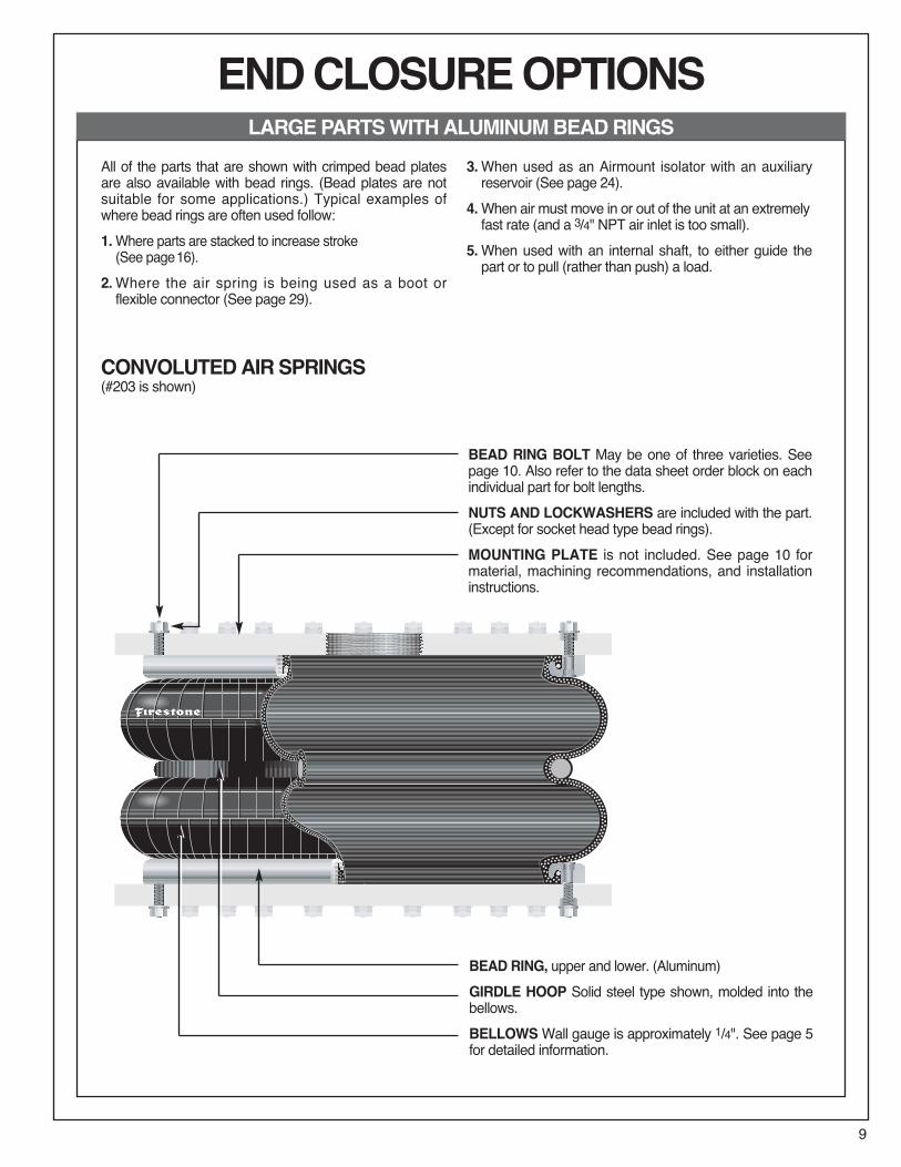
All of the parts that are shown with crimped bead platesare also available with bead rings. (Bead plates are notsuitable for some applications.) Typical examples ofwhere bead rings are often used follow:1.Where parts are stacked to increase stroke(See page16).
2.Where the air spring is being used as a boot orflexible connector (See page 29).
3.When used as an Airmount isolator with an auxiliaryreservoir (See page 24).
4.When air must move in or out of the unit at an extremelyfast rate (and a 3/4" NPT air inlet is too small).
5.When used with an internal shaft, to either guide thepart or to pull (rather than push) a load.
CONVOLUTEDAIRSPRINGS(#203 is shown)
BEAD RING BOLT May be one of three varieties. Seepage 10. Also refer to the data sheet order block on eachindividual part for bolt lengths.NUTS AND LOCKWASHERS are included with the part.(Except for socket head type bead rings).MOUNTING PLATE is not included. See page 10 formaterial, machining recommendations, and installationinstructions.
BEAD RING, upper and lower. (Aluminum)GIRDLE HOOP Solid steel type shown, molded into thebellows.BELLOWSWall gauge is approximately 1/4". See page 5for detailed information.
ENDCLOSUREOPTIONSLARGEPARTSWITHALUMINUMBEADRINGS

10
When using bead rings, THE CUSTOMER WILL NEEDTO FABRICATE HIS OWN MOUNTING PLATES. Hot orcold rolled steel provides satisfactory mounting surfaces,with specific finishes of 32 micro-inches, if machined in acircular fashion, and 250 micro-inches when ground (sideto side). The thickness of mounting plates depends uponthe application. The plates must be strong enough andbacked by structural members to prevent bowing (of theplates) when subjected to the forces or loads involved.The rubber bellows provides its own seal; therefore, ‘O’rings or other sealants are not needed when installing thepart.
INSTALLATIONFollow this technique for assembling a bead ring style bel-lows to the mounting plate:a. Insert the bolts into the bead ring (the bead rings havebeen previously attached to the bellows at the factory).The bolts will be pulled into place by the action of tighten-ing the nuts.
b. Slip all of the bolts (which are protruding through thebead ring) into the mating holes of the mounting plateand attach the lockwashers and nuts. FINGER TIGHT-EN all nuts to produce a uniform gap between the beadring and mounting plate all the way around.
c. At this point, make certain that the bellows bead is prop-erly seated under the bead ring.PLEASE NOTE THAT UNIFORM SUCCESSIVE TIGHT-ENING OF THE NUTS IS IMPORTANT TO SEAT THERUBBER BEAD PROPERLY TO THE MOUNTINGPLATE FOR ITS FULLCIRCUMFERENCE.Continue with the following sequence:
d. Tighten all nuts one turn each, moving around the circleuntil continuous contact is made between the bead ringand mounting plate.
e. Torque all nuts to the torque specifications shown on thepage, going at least two complete turns around the boltcircle.
MATERIALBead rings are supplied in either steel or aluminum. Boththe bead ring material and type of ring are called out in thedescription section of the order block on each individualdata page. Also, the bolt length (for the bolts supplied withthat particular order number) is given.WHERE A BEAD PLATE PART IS SHOWN AND THEBEAD RING ATTACHMENT IS PREFERRED, PLEASEREFER TO THE SELECTION GUIDE ON PAGE 32 FORBOLT CIRCLE DIAMETERS AND NUMBER OF BOLTS(EACHRING).
COUNTERSUNK STEELBEAD RING
RIBBED NECKALUMINUMBEAD RING
SOCKET HEADALUMINUM BEAD RING*
Optional Shorter LengthRibbed Neck Bolt
Used on4.5 in.BoltCirclesUse M6CapScrews,(NotIncluded)
CustomerSupplies Plate Effective
Length
BoltLength
CustomerSuppliesPlate
CustomerSupplies PlateEffective
Length
BoltLength
Standard Bolt Length (in.) StandardBolt Length (in.)1 5/8 1 7/8
StandardEffectiveLength (in.) StandardEffectiveLength (in.)1.22 1.28
StandardOrderNumber StandardOrderNumber(bolt only) (bolt only)
WC1-358-3625 WC1-358-3620Thread Thread
5/16-24UNF 3/8-24UNF
TighteningTorque (ft.-lbs.) TighteningTorque (ft.-lbs.)17 to22 28 to32
THEFOURTYPESOFBEADRINGS
BEADRINGSCONTINUED
10
When using bead rings, THE CUSTOMER WILL NEEDTO FABRICATE HIS OWN MOUNTING PLATES. Hot orcold rolled steel provides satisfactory mounting surfaces,with specific finishes of 250 microns, if machined in a cir-cular fashion, and 32 microns when ground.The thickness of mounting plates depends upon theapplication. The plates must be strong enough andbacked by structural members to prevent bowing(of the plates) when subjected to the forces or loadsinvolved. The rubber bellows provides its own seal;therefore, ‘O’ rings or other sealants are not needed wheninstalling the part.
INSTALLATIONFollow this technique for assembling a bead ring style bel-lows to the mounting plate:a. Insert the bolts into the bead ring (the bead rings havebeen previously attached to the bellows at the factory).The bolts will be pulled into place by the action oftightening the nuts.
b. Slip all of the bolts (which are protruding through thebead ring) into the mating holes of the mounting plateand attach the lockwashers and nuts. FINGER TIGHTENall nuts to produce a uniform gap between the bead ringand mounting plate all the way around.
c. At this point, make certain that the bellows bead isproperly seated under the bead ring.PLEASE NOTE THAT UNIFORM SUCCESSIVETIGHTENING OF THE NUTS IS IMPORTANT TO SEATTHE RUBBER BEAD PROPERLY TO THE MOUNTINGPLATE FOR ITS FULLCIRCUMFERENCE.Continue with the following sequence:
d. Tighten all nuts one turn each, moving around the circleuntil continuous contact is made between the bead ringand mounting plate.
e. Torque all nuts to the torque specifications shown onthe page, going at least two complete turns around thebolt circle.
MATERIALBead rings are supplied in either steel or aluminum. Boththe bead ring material and type of ring are called out in thedescription section of the order block on each individualdata page. Also, the bolt length (for the bolts supplied withthat particular order number) is given.WHERE A BEAD PLATE PART IS SHOWN AND THEBEAD RING ATTACHMENT IS PREFERRED, PLEASEREFER TO THE SELECTION GUIDE ON PAGE 32 FORBOLT CIRCLE DIAMETERS AND NUMBER OF BOLTS(EACHRING).
COUNTERSUNK STEELBEAD RING
RIBBED NECKALUMINUMBEAD RING
SOCKET HEADALUMINUM BEAD RING*
Optional Shorter LengthRibbed Neck Bolt
Used on4.5 in.BoltCirclesUse M6CapScrews,(NotIncluded)
CustomerSupplies Plate Effective
Length
BoltLength
CustomerSuppliesPlate
CustomerSupplies PlateEffective
Length
BoltLength
Standard Bolt Length (in.) StandardBolt Length (in.)1 3/4 1 7/8
StandardEffectiveLength (in.) StandardEffectiveLength (in.)1.22 1.28
StandardOrderNumber StandardOrderNumber(bolt only) (bolt only)
WC1-358-3625 WC1-358-3620Thread Thread
5/16-24UNF 3/8-24UNF
TighteningTorque (ft.-lbs.) TighteningTorque (ft.-lbs.)17 to22 28 to32
ENDCLOSUREOPTIONSTHETHREETYPESOFBEADRINGS
BEADRINGSCONTINUED
*Available only on style #16, #25, and #255-1.5

11
AIR INLET 3/4 NPT is standard. See the selection guideon page 32 for location (type 5). A centered 2" NPT airinlet is also available for some rolled plate parts. (ConsultFirestone).BLIND NUT 1/2-13 UNC thread x 3/4" deep (four eachplate). Used for mounting the part. A stud adapter for thissize blind nut is not available.UPPER BEAD PLATE (6 gauge carbon steel, .149").Permanently crimped to bellows to form an airtight assem-bly. Allows for leak testing before the unit leaves thefactory. Zinc/chromate plated for rust protection.
The convoluted parts, with 17, 20, and 22 inch diameter,are shown with bead rings as standard. We have devel-oped a method for permanently attaching plates to theselarger sized Airstrokes (called rolled plate assembly).These parts may be an advantage over the bead ringparts in some cases, because installation is much easier(they attach the same way as the bead plate parts).When installing the rolled plate parts, a backup plate aslarge in diameter as the bead plate must be used. Thisplate should be a minimum of 1/2 inch thick.
Again, for the blind nut and air entrance locations of rolledplate parts (bead rings are shown as standard on thedata pages), please refer to the selection guide on page32. The static data chart on each individual part may beused for the rolled plate version; but, two modificationsmust be made:1. Increase the minimum height by .70 inch.2. Add .70 inch to the height (bottom axis) beforereading loads.
.35 in.
ENDCLOSUREOPTIONSLARGEPARTSWITHROLLEDPLATES
CLAMP RING This ring is crimped up under the bel-lows bead to permanently attach the bead plate to thebellows. It is also zinc/chromate plated for rustprotection.LOWER BEAD PLATE Usually the same as upperbead plate, except without air inlet. See the selectionguide on page 32 for diameter (type 5).
LARGECONVOLUTEDAIRSPRINGS(#203 is shown, with rolled plates instead of bead rings)

12
HOWTOUSETHESTATICDATACHART
We also refer to this chart as the load/deflection(L/D) curve for an air spring. The force [1] is givenon the right hand axis vs. the air spring height [2]as shown along the bottom axis; thus, load vs.deflection. The internal volume [3] is also givenalong the left hand axis, again vs. height [2]. It iscalled static data because the air spring is in astatic, or non-moving, constant pressure condi-tion. In almost all cases the static curves were runusing a two ply bellows; however, where a fourply bellows is available, use the two ply chart for italso.
AIRSTROKEACTUATIONThe important considerations are minimumheight [4] (3.0 inches) and maximum recom-mended height [5] (10.1 inches). Subtracting onefrom the other gives the stroke potential for thispart (10.1 – 3.0 = 7.1 inches). As an actuator, theentire stroke may be used, or any potion thereof.Ignore recommended airmount design height [6]and the corresponding darkened line [7]. Thisheight is important in using the air spring as anisolator (AIRMOUNT). It has nothing to do withthe concern here of actuation. To determine theforce at any given height, simply move up theheight line to where it intersects any of the staticpressure curves. Then move to the right andread from the force scale [1].EXAMPLE: At 80 psig, what is the force using a#22 from 4.0 to 9.0 inches, or 9.0 – 4.0 = 5.0 inchstroke? See [8] for force at 4.0 inches (7,180 #)and [9] for force at 9.0 inches (4,670 #). Thisexample illustrates the primary differencebetween Firestone Airstrokes and conventionalair cylinders. Air cylinders have a constant areafor the pressure to work against, or constanteffective area. the effective area and force of anair spring changes as the height changes.(Thereis one exception: notice the plateau section ofreversible sleeve 1T type curves.)
Bumper Contact(4.2 IN.)
MAX. HT.
11
10
9
8
7
6
5
4
3
2
1
11
10
9
8
7
6
5
4
3
2
1
12 11 10 9 8 7 6 5 4 3
MIN. HT.[16][5]
[2] HEIGHT IN.
VOLU
ME
(WIT
HOUT
BUM
PER)
CUIN
.x10
0
[3]
FORC
ELB
Sx
1000
[1]
Static Data1227
[6]Recommended
AirmountDesign Height
9.5 Inches
Do not use Airstroke inshaded area withoutconsulting Firestone
[13]
752
120
100
80
60
40
20 Psig
Volume100 Psig
[12]
349[11]
4,2804,670
[14][15]
[9]
7,180[10]
[4]
[7]
[8]

13
In the example the effective area of a #22, at 4.0 inches usingthe 80 psi curve, is:
7,180 lbs.80 Ibs/in2 = 89.8 in2
at 9.0 inches in height it is:4,670 lbs.80 Ibs/in2 = 58.4 in2
An air cylinder with 89.8 in2 of area would have an 80 psi curveas shown by dotted line [10].The volume curve [3]may also be of importance:a. If one needs to know the amount of free air (then com-pressed by the compressor) to perform a desired operation.
b. If the actuation must be completed quickly and calculationsof flow through the air inlet (orifice) are required.
In each case above, the change in internal volume is required.Read up from the two heights involved to the intersecting pointwith the volume curve. Then move to the left and read from thevolume scale. In the example at 4.0 a #22 (notice most volumecurves are at 100 psig) has an internal volume of 349 in3 [11]and at 9.0 the volume is 752 in3 [12]. The change in volume isthen 752 in3 – 349 in3, or 403 in3. The volume at minimumheight (349 in3) would not be subtracted if exhausting the airspring to atmospheric pressure.Notice the shaded area [13]. We do not recommend that anair spring be used at heights extending into this section. The“beginning of the shaded area” for a #22 is at 101 inches [5].SEE PAGE 15 FOR A MORE DETAILED DISCUSSION OFACTUATION.
AIRMOUNT ISOLATIONBecause of lateral stability considerations (see page 23 formore details) we recommend that each air spring be used at aspecific height when used as an isolator. This specific height iscalled the “Airmount design height” [6]. The vertical line runningthrough this height [7] is darkened so that it is easy to seewhere it intersects the static curves for load readings.
EXAMPLE: Support a 4,100 pound load with an air spring.Would a #22 be appropriate, and if so, at what height? Theheight isn’t much of a problem, as this part SHOULD BEUSED AT 9.5 INCHES. Simply move up the darkened line towhere it intersects 4,100 Ibs [14]. That point falls between the80 and 60 psig curves. Exactly what pressure would berequired? Use the formula:
Effective Area = Load (Ibs.)Pressure (Ibs/in2)
Determine the effective area at 9.5 inches (using the 80 psigcurve, since 80 psig would be closer to our exact pressurethan 60 psig), or:
Effective Area = 4,280 Ibs. [15] = 53.5 in280 Ibs/in2
Then divide the actual load by the effective area:4,100 Ibs. = 76.6 PSIG53.5 in2
The pressure required to support 4,100 Ibs. with a #22 at adesign height of 9.5 inches is therefore 76.6 PSIG.Please note that the static data can be converted to dynamicdata (the air spring is in motion) by applying the formulas thatare presented in the Airmount isolation section on page 22.SEE PAGE 21 FOR A MORE DETAILED DISCUSSION OFVIBRATION ISOLATION.
INTERNALRUBBERBUMPERSSome parts are available with internal rubber bumpers. Wherea bumper is available, it is shown as a dotted line in the crosssectional view of the air spring. Additionally, please note that:1. the minimum height is increased to the “bumper contact”point [16] (this reduces the total available stroke somewhat,by 4.2 – 3.0 = 12 inches in our #22 example), and
2. the order block contains the proper ordering numbers forparts with bumpers.

14
BASICPARAMETERSAPPLICABLETOBOTHAIRSTROKE™ ACTUATORSAND
AIRMOUNT™ ISOLATORSMEDIAAir springs are designed for use with compressed air. Nitrogenis also acceptable. Air springs may be filled with water or water-glycol (automotive antifreeze) solutions. If water is to be used,rust inhibitors should be added to protect the end closures. Tworeasons for liquid filling an air spring are:1. To reduce the internal volume of air (and therefore, increasethe natural frequency of the air spring) and,
2. To use a media which is incompressible. Accurate positioningwould be one reason to do this.
Petroleum base fluids (most hydraulic oils fall into this category)are NOT RECOMMENDED. Moderately lubricated air will notharm the bellows.
PRESSURE1. 100 PSIG MAXIMUM FOR 2 PLY.2. 175 PSIG MAXIMUM FOR HIGH STRENGTH.
We recommend that there be a minimum three times safety fac-tor between maximum internal air pressure and burst pressure.So, as an example, if 100 psig is required, the burst should be at300 psig or greater. For convoluted air springs, the burst pres-sure decreases as height increases. Therefore, the determiningfactors are twofold: What is the maximum height into extensionand what is the internal pressure at that point? Please see theAirstroke Inflation Pressure Chart (for single, double, and tripleconvoluted air springs) on page 17 for specific pressure vs.height information.For AIRMOUNT applications (where the part is used at aheight very close to the shaded area), it is best to stay within100 psig maximum for a two ply, and 150 psig maximum for afour ply or high strength cord air spring.
STORAGEThe best storage environment is a dark, dry area at normalroom temperature.
TEMPERATURE1. STANDARD BELLOWS. Our standard industrial air springsshould be limited to use in the range:– 35° F to + 135° F.
2. ALL NATURAL RUBBER (LOW TEMPERATURE COM-POUND). A few of our industrial air springs are available inall natural rubber construction. This increases the accept-able cold or low end of the scale to – 65° F. The range thenbecomes – 65° F to +135° F.
3. EPICHLOROHYDRIN (HIGH TEMPERATURE COM-POUND). Most convoluted parts are available in thismaterial. The operating temperature range for it is: 0° F to225° F. Additionally, Epichlorohydrin has very good oil resis-tance. ALL EPICHLOROHYDRIN APPLICATIONS MUSTBE APPROVED BY FIRESTONE. For more information onEpichlorohydrin (also known as Herclor), ask forTechnigram number 111.
4. NEOPRENE (HIGH TEMPERATURE COMPOUND).Neoprene is more resistant to damage from oil. For thisreason, Firestone Neoprene has been used as the insidelayer in two configurations to reduce the hazard of having oilin the pneumatic plumbing system. The third configurationincludes an outer layer of Firestone Neoprene for applica-tions that expose the exterior of the air spring to an oilenvironment. In addition, Firestone Neoprene is able towithstand higher temperatures than natural rubber (-35º to+165º F).
CONTAMINATESShielding should be used to protect the bellows from exposureto hot metal, sand, petroleum base fluids, acids, etc. Pleaseconsult Firestone if you wish to know how the bellows will with-stand a specific contaminant (For liquids such as acids, it isimportant to know both concentration and temperature).
WARNINGDO NOT INFLATE ASSEMBLY WHEN IT IS UNRESTRICTED. ASSEMBLYMUST BE RESTRICTED BY SUSPENSION OROTHER ADEQUATE STRUC-TURE. DO NOT INFLATE BEYOND PRESSURES RECOMMENDED INDESIGN LITERATURE (CONTACT FIRESTONE FOR INFORMATION).IMPROPER USE OR OVERINFLATION MAY CAUSE ASSEMBLY TOBURST CAUSING PROPERTY DAMAGEOR SEVERE PERSONAL INJURY.

15
AIRSTROKEACTUATIONSELECTION1.Refer to the selection guide on page 32 for Airstroke forceand stroke capabilities. After your list of possibilities has beenreduced to one or two air springs, then turn to the individualdata page for more detailed information on those parts.
2. STROKE: The maximum STROKE CAPABILITY is the dif-ference between the height corresponding to the “start ofthe shaded area” minus the minimum height. This entirestroke, or any portion thereof, may be used. If an internalrubber bumper is required, please note that the minimumheight is increased, and therefore, the total stroke isdecreased.
3. FORCE: Read the forces directly from the static data chart,or, use the force table located under the chart. Notice thatthe force generally decreases as height increases. This fea-ture is discussed in detail on page 12 in the section entitled“How to Use the Static Data Chart.”
4. SELECT THE END CLOSURES AND AIR INLET SIZE:Most Airstroke actuators are available with permanentlyattached plates or bead ring attachments. If an alternate endclosure option is available, it is so stated under the crosssectional view of the part. Please refer to page 6 for adetailed discussion of end closure options.
DOWNANDUPSTOPSPositive stops in both directions (compression and exten-sion) should always be used with Airstroke actuators .1. In COMPRESSION, the minimum height shown for each airspring is at, or slightly above the PINCH POINT of the bellows.Here is a #22 shown in the collapsed or “pinch point” condition:
The bellows can be damaged if allowed to constantly bot-tom out as shown above; therefore, a downstop is requiredto prevent this. An external downstop can be something assimple as a steel block and should be sized at or slightlygreater than the minimum height of the Airstroke. In our #22example, the block would need to be at least 3.0 incheshigh. If an external downstop cannot be used, many partsare available with internal rubber bumpers (shown as adotted line in the cross-sectional view of the air springwhere available).
2. In EXTENSION, an upstop is required to prevent the airspring from overextending at heights into the shaded area ofthe graph. The reasons for this are twofold: a) the life of thebellows may be reduced and b) the crimp may open up,allowing the bellows bead to blow out of the metal end clo-sure. There are many ways to design-in an upstop, including
a. a chain,b. a cable,c. contacting a metal stop, etc.
RETURNAn Airstroke actuator is a single acting device. To return theAirstroke to its minimum height (for another cycle or stroke),some return force must be used. Gravity acting on the loadmay be all that’s required. The force to collapse the convolutedtype Airstrokes to minimum height is given in the order blocksection for each part. If the load is not sufficient, then a secondAirstroke or coil spring may be required.
GUIDINGAn Airstroke follows the path of least resistance; therefore, theactuator should be guided in most instances. This is often eas-ily accomplished in the mounting geometry.
ANGULARCAPABILITYAn Airstroke actuator can stroke through an arc (without a cle-vis). Angular motion of up to 30 degrees is possible. Whenusing an actuator with the mounting plates at an angle to eachother, observe the following:a.Measure force at the height between the plate centers.b.Measure maximum height at the side separatedthe furthest.
c.Measure minimum height at the side collapsed the most.
3.0

16
Angular Capability continuedThese measurements must fall within the guide lines for thatparticular part. Consider style #22 in the following scissorsarrangement:
Reversible sleeve Type 1T parts may also stroke through anarc. In this case, care must be taken to prevent the bellows fromrubbing (internally) against itself where it rolls over the piston:
HORIZONTALMISALIGNMENTThe upper and lower bead plate centers (or mounting platecenters in the case of a bead ring type attachment) may be outof line somewhat without injury to the bellows. Our “rule ofthumb” for convoluted type Airstrokes is one inch misalignmentallowed per convolution. So, a single convoluted air springmay be out of line by as much as 1 inch, a double by 2 inches,and a triple convoluted air spring by 3 inches.
DESIGNENVELOPEAdequate clearance should be provided around the Airstroketo prevent puncturing or rubbing of the bellows. The maximumdiameter @ 100 psig for each Airstroke (bellows) is locatedjust above the cross-sectional view of the air spring.
STACKINGIt is permissible to stack Airstrokes (one on top of another) toincrease stroke; however, the center plate (or plates) connect-ing the two or more Airstrokes MUST BE GUIDED.
Please note that the air spring forces are not additive in thisconfiguration. A method for guiding, which also illustrates onecenter ring concept for mounting the two parts together at themiddle, is illustrated below:
FAILSAFEDEVICESSome applications require the use of fail safe mechanisms(such as a mechanical lock-out on a scissors lift) to preventdamage or injury in the event of an air system failure.
VACUUMAn Airstroke can withstand a small amount of vacuum withoutinjury to the bellows. The maximum amount of acceptable vacu-um is dependent upon the bellows’ size, the height in use, andwhether it is a two ply or high strength (fabric) air spring. (A highstrength Airstroke bellows has a “stiffer” wall than a two ply;therefore, it is less susceptible to dimpling and deformationinward). It is generally best to use only single convoluted airsprings under vacuum.
An Airstroke Design Parameter Worksheetcan be found on page 105.
Max Ht(Must be ≤ 10.1)
Bellows mustnot rub against
itself here.
Max Ht(Must be ≥ 3.0)
CalculateForce Here
PivotPoint
#22 Center Ring
Customer MustSupply Button
Head-Socket HeadCap Screws

17
AIRSTROKEINFLATIONPR
ESSU
RECH
ART
MAX
IMUM
RECO
MMEN
DEDINTERN
ALPR
ESSU
RESFO
RCO
NVOL
UTED
TYPE
AIRS
TROK
E™AC
TUATOR
APPLICATIONS
BASE
DONAP
PROXIMATELY1 /3
NORM
ALBU
RSTVA
LUES
APPL
ICATIONS
WHICH
EXCE
EDTH
ESELIMITSSH
OUL
DBE
REVIEW
EDWITHFIRE
STONE
.
1816.5
1513.5
1210.5
97.5
64.5
1211
109
87
65
43
6.5
65.5
54.5
43.5
32.5
2
TRIPLE
CONV
OLU
TED
DOUB
LECO
NVOLU
TED
SING
LECO
NVOLU
TED
OVE
RALL
AIRS
TROKE
HEIGHT
(INCH
ES)
CONS
TRUC
TIONBE
ADPLATEAN
D
BEAD
PLATEAN
DBE
ADRING
STYLE
ROLLED
PLATESTYLE
BEAD
RING
STYLE
TWOPLY
250
200
150
100
50 0
PRESSURE(PSIG)
REFERTO
EACH
INDIVIDU
ALDA
TAPA
GEFO
RMAX
IMUM
USAB
LEHE
IGHT
RESTRICT
IONS
HIGH
STRE
NGTH

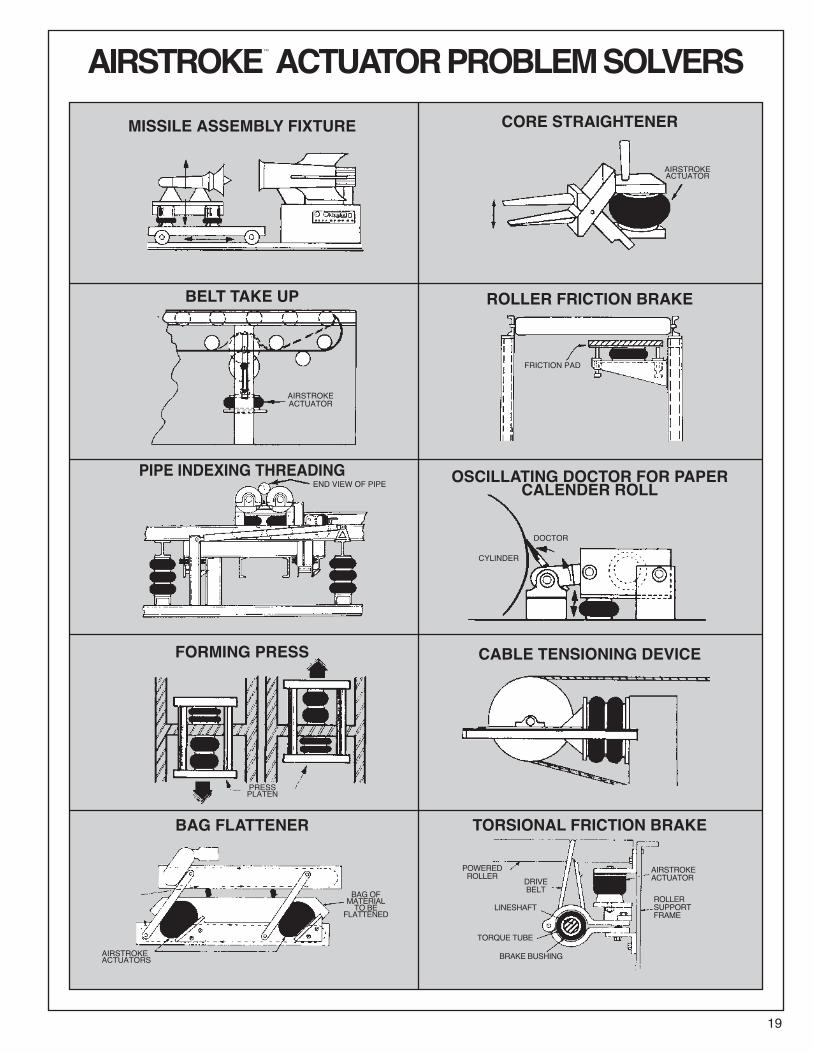
AIRSTROKE™ ACTUATORPROBLEMSOLVERS
18
GATE VALVE OPERATOR GLUING PRESS
WEB TENSIONING DEVICE DIE STRIPPER
KNIFE SPRING ACTUATOR QUENCH TANK ACTUATOR
PAPER SIZING PRESS PICKLING TANK ACTUATOR
QUICK LOCK DEVICE PRESSURE ROLL FOR CALENDER
AIRSTROKE ACTUATORSQUENCH TANK
UPPER & LOWER POSITIVE STOPS
KNIFE
AIR LINES
ACID TANK
WIRE COILS
ACID
FRAME
PRESS
PIVOT
LOG
ROTATION
PAPERAIRSTROKEACTUATOR
AIRSTROKE™ ACTUATORPROBLEMSOLVERS
19
MISSILE ASSEMBLY FIXTURE CORE STRAIGHTENER
BELT TAKE UP ROLLER FRICTION BRAKE
PIPE INDEXING THREADING OSCILLATING DOCTOR FOR PAPERCALENDER ROLL
CABLE TENSIONING DEVICE
BAG FLATTENER TORSIONAL FRICTION BRAKE
FORMING PRESS
AIRSTROKEACTUATOR
AIRSTROKEACTUATOR
END VIEW OF PIPE
DOCTOR
PRESSPLATEN
AIRSTROKEACTUATORS
BAG OFMATERIALTO BE
FLATTENED
POWEREDROLLER DRIVE
BELT
LINESHAFT
TORQUE TUBE
BRAKE BUSHING
AIRSTROKEACTUATOR
ROLLERSUPPORTFRAME
CYLINDER
FRICTION PAD

20
AIRSTROKE™ ACTUATORPROBLEMSOLVERSHINGED GATE HOT FOIL STAMPING PRESS
ACTUATED HEAVY DUTY SEALER PIVOTED CLAMPING DEVICE
AIRSTROKE ACTUATED ROLLER STOP HINGED ACTUATED GRAVITY GATE
VERTICAL ACTUATED DRIVE TABLE SCISSOR LIFT
CASE PACKER CONVEYOR TRANSFER ACTUATOR
AIRSTROKEACTUATOR
AIRSTROKEACTUATOR
AIRSTROKEACTUATOR
AIRSTROKEACTUATOR
RETURN TENSIONSPRING
RUBBERSTOP
ADJUSTABLECOLLAPSEHEIGHT
TOP OF CHAIN IN HIGH POSITIONTOP OF CHAIN IN LOW POSITION
FIXED STOP
AIRSTROKEACTUATOR
AIRFITTING
COMPRESSED POSITION
EXTENDED POSITION
TORSIONSPRINGHINGE OPEN
CLOSED
WEIGHHOPPER
AIRSTROKEACTUATOR

21
AIRMOUNT™ VIBRATION ISOLATIONSELECTIONAND ISOLATIONFORMULARefer to the selection guide on page 33 for Airmount load andisolation capabilities. Follow this procedure:
1. LOADCAPACITYSelect one or two Airmounts that can support the load at eachmounting point. It is normally best to design for pressures inthe 60 to 80 psig range. Consider only the 1M1A-0 and thesingle and double convoluted types at first. Please notice thatin the range of 210 to 63,890 pounds you will, in most cases,find both a single and double convoluted style part which willsupport the load.
2. DETERMINE ISOLATIONEFFECTIVENESSSelect the disturbing frequency that is closest to the actualforced frequency (400, 800, or 1500 cpm). Then check the per-centage of isolation for the parts that were selected in 1 above.
3. DETERMINEDESIGNHEIGHTTHE AIR SPRING SHOULD BE USED AT THE DESIGNHEIGHT GIVEN. The double convoluted part is used at adesign height somewhat higher than its single convolutionequivalent. Make sure that the design height falls within theheight restrictions. Also, the double convoluted part will show ahigher percentage of isolation (less transmitted vibration) thanthe single convoluted air spring. The reason for this is that thedouble convoluted part has a greater internal volume of airthan the single convoluted version of the same size. At disturb-ing frequencies in the 400 to 800 cpm range, the doubleconvoluted part is a significantly better vibration isolator thanthe single convoluted part. At disturbing frequencies of 800 to1500 cpm, the gap closes considerably. At frequencies of1500 cpm and above, the difference is negligible.
4. DETERMINEEXACT INTERNALPRESSUREAND ISOLATIONEFFECTIVENESS
The chances are that your specific vibration problem does notfall neatly into the load and disturbing frequency criteria as pre-sented in the selection guide.Therefore, once a preliminary part selection has been made,turn to the individual data page for that part in order to deter-mine the specific internal pressure required and thepercentage of isolation attainable.
CONSIDER THIS EXAMPLE:Isolate a vibrating screen which weighs a total of 16,400pounds, preferably with one isolator at each corner. The vibrat-ing mechanism is rotating at a speed of 850 rpm (cpm) with atotal stroke of 5/16 inch.a. Determine the load at each mounting point:
Scan down the 80 psig load column in the selection guide. Itappears that either a #19 or a #22 will support the load at apressure between 60 and 80 psig.
b. Determine Isolation Effectiveness.Read the % of Isolation at 800 cpm for the #19 and #22(since 800 is closest to our machine speed of 850 cpm). A #19is at 96.0% and a #22 is at 98.2%. Looking at isolation effec-tiveness in terms of % TRANSMISSION, the #19 will transmit100 – 96.0, or 4.0% of the vibrations. A #22 will transmit100 – 98.2, or 1.8% of the vibrations. So, even though theredoes not seem to be much difference between 96.0% and98.2% isolation, the #22 is in fact a better isolator by approxi-mately a factor of two when comparing transmitted vibration.
c. Determine Design Height.Let’s say we have chosen the #22 because 96.0% isolation fora #19 is considered to be too low. A #22 should be used at 9.5inches as shown in the second column on page 33.
d. Determine Exact Internal Pressure and Isolation Percentage.Turn to page 61 for detailed information on the #22.a)What exact pressure will be required to support the loadof 4,100 Ibs? Refer to the information in the block entitled“Dynamic Characteristics at 9.5 in Design Height.”
Divide the actual load by the effective area:
4= 4,100 lbs.
4,280 lbs.80 lbs/in2 53.5 in2 effective area @ 9.5 inches
@ 80 psig= =
4,100 lbs.53.5 in2 76.6 psig required to support
4,100 lbs. at 9.5 inches=
16,400

22
AIRMOUNT™ VIBRATION ISOLATIONb)What exact isolation will be attained?Use the formula:
Where: ff = Forced Frequencyfn = Natural Frequency
The forced frequency is 850 cpm Read the natural frequencyfrom the line at the load and pressure closest to the actual situ-ation, or 106 CPM (@ 80 psig and 4,280 Ibs.):
% Transmission = 1.6%% Isolation = 100 – % Transmission% Isolation = 100 – 1.6% Isolation = 98.4%
Notice that the natural frequency of an Airmount changes onlyslightly with variations in pressure and load. Therefore, whenworking at pressures other than 40, 60, 80, or 100 psig, % iso-lation can be calculated quite accurately using the “closest”natural frequency and the formula above.
DYNAMICSPRINGRATEFORMULASpring rate is a different matter. Unlike most conventionalsprings, the rate of an Airmount is not constant. It is a functionof the change in effective area, volume, and pressure fromdesign height. To determine the rate of an Airmount, use thefollowing formula:
K=[[Pg +14.7] Ac1.38– Ae
1.38 –14.7(Ac–Ae)]lbs
WHERE:K = Vertical Spring Rate in Ibs./inchPg = Gauge Pressure at design heightAc = Effective Area at 1/2 inch below design height (in2)Ae = Effective Area at 1/2 inch above design height (in2)V1 = Internal Volume at design height (in3)Vc = Internal Volume at 1/2 inch below design height (in3)Ve = Internal Volume at 1/2 inch above design height (in3)
Consider the same #22 example: What is the vertical springrate with a load of 4,100 pounds at a design height of 9.5inches? Refer to the static data chart on page 62. Again,our “closest" pressure is 80 psig, so we'll need to read theappropriate data from the 80 psig curve.The 80 psig information at 1/2 inch above design heightwould fall at the 10.0 inch height line, and 1/2 inch belowdesign height would fall at the 9.0 inch height line. (In thisexample, we can read loads from the force table). Theinformation at design height is located in the “DynamicCharacteristics Block.” So,K = UnknownPg = 76.6 psig (see page 13)
V1 = 782 in3
Vc = 752 in3
Ve = 809 in3
K=[[Pg +14.7] Ac 1.38– Ae 1.38 –14.7(Ac–Ae)]lbs
K=[[76.6+14.7] 58.4 1.38–47.6 1.38 –14.7
K = 1,324 lbs/inch
NATURALFREQUENCYFORMULAOnce the spring rate is determined, calculate the Airmountnatural frequency (for an undamped system) as follows:
Where:fn = Natural Frequency in cycles per minute (cpm)K = Rate (Ibs/inch)L = Load (pounds)
in our example:
fn = 106.8 cpm
( )% Transmission = 100
fffn
– 12
( )% Transmission = 100
106– 12
850
[ ( ) ( ) ]V1Vc
V1Ve
[ ( ) ( ) ]V1Vc
V1Ve
1inch
[ ( ) ( ) ]782752
782809
( )lbsin2 n
A = 58.4 in2 =c ( )4,670 lbs.80 lbs/in2
A = 47.6 in2 =e ( )3,810 lbs.80 lbs/in2
f = 188 √ KL
nf = 188 1,3244,100
1inch
1inch(58.4–47.6)
√
1.38 1.38
1.38 1.38
1.38 1.38

23
AIRMOUNT™ VIBRATION ISOLATIONUp to this point, only the weight and disturbing frequency havebeen discussed. THERE ARE MANY OTHER IMPORTANTCONSIDERATIONS:
CENTEROFGRAVITYAn Airmount isolation system is inherently soft (easily deflect-ed); therefore, precautions must be taken to insure that thesystem is stable. First, consider the location of the center ofgravity (c.g.). Ideally, the Airmounts should be located on thesame plane (parallel to the ground) as the center of gravity.Where this is not possible, follow this guideline: The distancebetween the most narrow mounting points should be at leasttwice the height of the center of gravity.
In the above example, the most narrow distance between twoAirmounts is 46 inches The height to the c.g. is 48 inches;therefore, this system does not meet our guideline. Two pos-sible solutions would be:1. Increase the base dimensions to meet our guideline byincreasing both the width and length to at least 48 x 2 or96 inches.
2. Locate the Airmounts at the c.g. as shown above (in thenext column).
LATERALRATESANDSTABILITYSingle and double convoluted air springs SHOULD BE USEDAT THE DESlGN HEIGHTS GIVEN, because that is the pointof maximum lateral rate or stability. The lateral rate decreasesas the Airmount height decreases. Consider a #22 again at80 psig:
Notice that the #22 becomes unstable in the horizontal or lateraldirection when moving down only two inches from design height.
Height Lateral Rate Vertical Rate
9.5 inch (design height) 325 lbs/in 1,373 lb/in
8.5 inch 212 lbs —
7.5 inch Unstable —
Height 48"
Width 46"Length 50"
24
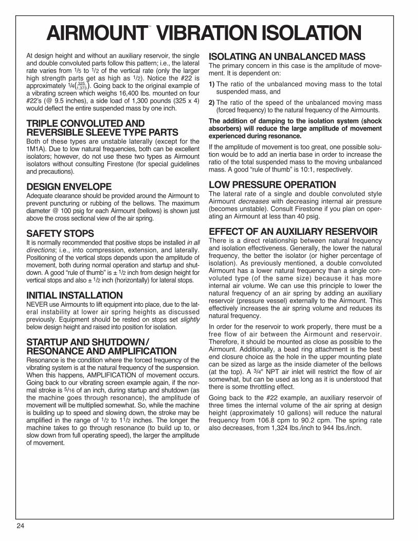
AIRMOUNT™ VIBRATION ISOLATIONAt design height and without an auxiliary reservoir, the singleand double convoluted parts follow this pattern; i.e., the lateralrate varies from 1/5 to 1/2 of the vertical rate (only the largerhigh strength parts get as high as 1/2). Notice the #22 isapproximately 1/4( ). Going back to the original example ofa vibrating screen which weighs 16,400 Ibs. mounted on four#22’s (@ 9.5 inches), a side load of 1,300 pounds (325 x 4)would deflect the entire suspended mass by one inch.
TRIPLECONVOLUTEDANDREVERSIBLESLEEVETYPEPARTSBoth of these types are unstable laterally (except for the1M1A). Due to low natural frequencies, both can be excellentisolators; however, do not use these two types as Airmountisolators without consulting Firestone (for special guidelinesand precautions).
DESIGNENVELOPEAdequate clearance should be provided around the Airmount toprevent puncturing or rubbing of the bellows. The maximumdiameter @ 100 psig for each Airmount (bellows) is shown justabove the cross sectional view of the air spring.
SAFETYSTOPSIt is normally recommended that positive stops be installed in alldirections; i.e., into compression, extension, and laterally.Positioning of the vertical stops depends upon the amplitude ofmovement, both during normal operation and startup and shut-down. A good “rule of thumb” is ± 1/2 inch from design height forvertical stops and also ± 1/2 inch (horizontally) for lateral stops.
INITIAL INSTALLATIONNEVER use Airmounts to lift equipment into place, due to the lat-eral instability at lower air spring heights as discussedpreviously. Equipment should be rested on stops set slightlybelow design height and raised into position for isolation.
STARTUPANDSHUTDOWN/RESONANCEANDAMPLIFICATIONResonance is the condition where the forced frequency of thevibrating system is at the natural frequency of the suspension.When this happens, AMPLIFICATION of movement occurs.Going back to our vibrating screen example again, if the nor-mal stroke is 5/16 of an inch, during startup and shutdown (asthe machine goes through resonance), the amplitude ofmovement will be multiplied somewhat. So, while the machineis building up to speed and slowing down, the stroke may beamplified in the range of 1/2 to 11/2 inches. The longer themachine takes to go through resonance (to build up to, orslow down from full operating speed), the larger the amplitudeof movement.
ISOLATINGANUNBALANCEDMASSThe primary concern in this case is the amplitude of move-ment. It is dependent on:1) The ratio of the unbalanced moving mass to the totalsuspended mass, and
2) The ratio of the speed of the unbalanced moving mass(forced frequency) to the natural frequency of the Airmounts.
The addition of damping to the isolation system (shockabsorbers) will reduce the large amplitude of movementexperienced during resonance.If the amplitude of movement is too great, one possible solu-tion would be to add an inertia base in order to increase theratio of the total suspended mass to the moving unbalancedmass. A good “rule of thumb” is 10:1, respectively.
LOWPRESSUREOPERATIONThe lateral rate of a single and double convoluted styleAirmount decreases with decreasing internal air pressure(becomes unstable). Consult Firestone if you plan on oper-ating an Airmount at less than 40 psig.
EFFECTOFANAUXILIARYRESERVOIRThere is a direct relationship between natural frequencyand isolation effectiveness. Generally, the lower the naturalfrequency, the better the isolator (or higher percentage ofisolation). As previously mentioned, a double convolutedAirmount has a lower natural frequency than a single con-voluted type (of the same size) because it has moreinternal air volume. We can use this principle to lower thenatural frequency of an air spring by adding an auxiliaryreservoir (pressure vessel) externally to the Airmount. Thiseffectively increases the air spring volume and reduces itsnatural frequency.In order for the reservoir to work properly, there must be afree flow of air between the Airmount and reservoir.Therefore, it should be mounted as close as possible to theAirmount. Additionally, a bead ring attachment is the bestend closure choice as the hole in the upper mounting platecan be sized as large as the inside diameter of the bellows(at the top). A 3/4" NPT air inlet will restrict the flow of airsomewhat, but can be used as long as it is understood thatthere is some throttling effect.Going back to the #22 example, an auxiliary reservoir ofthree times the internal volume of the air spring at designheight (approximately 10 gallons) will reduce the naturalfrequency from 106.8 cpm to 90.2 cpm. The spring ratealso decreases, from 1,324 Ibs./inch to 944 Ibs./inch.
3251,373

25
AIRMOUNT™ VIBRATION ISOLATIONDAMPINGDamping is defined as the ratio:WHERE: C = System Damping
Cc = Critical DampingThe damping ratio inherent in an Airmount is in the order of.03. This damping number is so small that the formulas pre-sented in this section assume it to be zero.
PLUMBINGSYSTEMSThere are three basic ways of controlling an air suspendedisolation system:1. Tank Valve System With a tank valve in each Airmount,each air spring is then inflated individually. The pressurein each must be checked periodically, because air willpermeate through the bellows.
For an idea of the permeation rate, a #116 will lose approxi-mately 30 psig over a period of one year (from 100 psig to70 psig). Please see page 7 for a picture of a 1/4" NPT tankvalve.2. Three Point Regulated System The Airmounts can beconnected directly to the factory compressed air systemusing pressure regulating valves. This eliminates the
need for periodic inspections. The air springs should alwaysbe connected in clusters so the mass is supported with onlyTHREE REGULATORS. This is illustrated below (in theprevious column) for both a four and eight Airmount system:3. Three Point Leveled System Height control can be pro-vided by adding height control valves to the system.Again, there should be only THREE POINTS OF CON-TROL, or in this case, three leveling valves. Attemptingto use more than three control points often results in thevalves hunting or fighting one another. There are sensingsystems available to control heights within ±.001 inch.Truck type leveling valves can provide accuracy to ±1/16inch. A three point, eight air spring, leveled system isillustrated below:
An Airmount Design Parameter Worksheetcan be found on page 107.
CCc
AIRSPRING
AIRSPRING
AIRSPRING
AIRSPRING
AIRSPRING
AIRSPRING
AIRSPRING
AIRSPRING
AIRSPRING
AIRSPRING
TO AIRSUPPLY
TO AIRSUPPLY
CHECKVALVE
LEVELINGVALVE
LEVELINGVALVE
LEVELINGVALVE
TO AIRSUPPLY
REGULATORS
REGULA-TORS
REGULATORS
AIRSPRING
AIRSPRING
AIRSPRINGS
AIRSPRINGS
AIRSPRINGS
AIRSPRINGS
CHECKVALVES
CHECKVALVES
Description Order No.Time Delay Valve WC1-358-3592

FORC
EDFR
EQUE
NCY
(f f)
NATURAL FREQUENCY (fn)
300.50
400.67
500.83
601.0
801.33
1001.67
1502.50
2003.33
3005.00
4006.67
5008.33
60010.0
80013.3
100016.7
CPMHERTZ
300025002000
1500
1000900800700600500
400
300250
200
150
100
5041.733.2
25
16.715
13.311.7
108.3
6.7
5.04.2
3.3
2.5
1.7
CPMHERTZ
Amplification
98 97 969599.5 99 708090 6099.9Perc
ent
Isolat
ion
Resona
nce
26
AIRMOUNT™ VIBRATION ISOLATIONISOLATIONCHART

27
AIRMOUNT™ ISOLATIONPROBLEMSOLVERS
COMMERCIAL LAUNDRY MACHINE
BIN HOPPER
VIBRATING PACKER
COMPRESSOR

28
AIRMOUNT™ ISOLATIONPROBLEMSOLVERSCONTROL BOOTH
VIBRATING SCREEN
BLOWER AND MOTOR
CONTROL PANEL

29
MISCELLANEOUSAPPLICATIONSThe air spring provides a unique solution for many actuationand isolation applications the world over. Besides the commonapplications, there are many that are not readily recognizedbecause of the air spring’s unique construction. Listed beloware some miscellaneous applications.
SHOCK IMPACT ISOLATIONThe air spring is frequently used in shock impact isolationapplications. This air spring application is commonly found insaw mills as the means to both absorb the shock of a fallinglog, and then by actuating the air spring, to lift and transfer alog onto a conveyor. Because of the properties of both air andrubber, the air spring is an ideal solution to this problem.Without it, the mechanism and surrounding structure wouldsuffer fatigue and fail prematurely due to the intensity of theshock from the falling log. Refer to the problem solver sectionon the following pages for miscellaneous applications.
PROTECTIVEBOOTANDFLEXIBLECONNECTORAn air spring bellows, with a bead ring type attachment, can beused as a protective boot or flexible connector. Due to the flex-ible construction of the air spring and the ability to handle bothmisalignment and angular movement, the air spring is a suit-able solution to this problem. To protect the inner surface fromthe flow of material, an inner sleeve may be required. Refer tothe problem solver section on the following pages for miscella-neous applications.
VACUUMPUMPIt is possible to drive an air spring mechanically in order to cre-ate a vacuum. The air spring can withstand a small amount ofacceptable vacuum without injury to the bellows. The maxi-mum amount of tolerable vacuum is dependent upon thebellows’ size, height and whether it is a 2 ply or high strengthair spring. It is generally best to use only the single convolutedair spring for this purpose. Refer to the problem solver sectionon the following pages for miscellaneous applications.
INFLATABLECHUCKBy restricting the height internally of a bead ring style air spring,the rubber walls will extend in an outward fashion. In thisarrangement the air spring can be used as an inflatable chuck.The air will need to be introduced via the same mechanism thatrestrains the air spring’s height. Refer to the problem solversection on the following pages for miscellaneous applications.
CAMFOLLOWERThe introduction of an air spring as the cam follower canextend the life of the cam greatly. Surface wear is reduced byremoving the rigidity and friction of typical cam followers. Withthis reduction of wear comes continually smooth operationsand overall minimization of fatigue. Refer to the problem solversection on the following pages for miscellaneous applications.
AIRSPRINGROTATING
CAMHEATINGPLATEN
INDEXING CONVEYORSYSTEM
EXTENDED
COLLAPSED VACUUM CYLINDERSPRING RETURN
PREPRINTED LABELSINDEXED IN
RETURNSPRING
PACKAGEOF MEAT
ROTATINGSHAFT
AIR ENTRANCE
TUBE
AIRSTROKE
CHECKVALVE
AIRMOUNT
CONVEYOR RAIL
CARRIAGE
AIRSTROKE
PIPE HYPALONSLEEVE
For more information, call your local stocking distributor or theFirestone applications engineer at the phone number on theback cover of this design guide.

30
AIRSTROKE
END VIEW
MISCELLANEOUSPROBLEMSOLVERSROBOTIC COUPLING CONVEYOR END STOP
SHOCK ABSORBER TEST SYSTEMMOUNTAIN/TRAIL BIKE
SCREENING MACHINE COVER CLAMP PIPE CRAWLER
VIBRATING SCREENDELICATE ELECTRONIC EQUIPMENT

31
MISCELLANEOUSPROBLEMSOLVERSSHEET WELDING CLAMP
PERFECT BOUND MAGAZINE CUTTER
CHECK VALVE LAPPING
AIR BLAST GENERATOR
SWASH PLATE MOTOR
WAVE POWER MODULE
SELF ALIGNING DEVICE
SOLAR TRACKER


�
�
�
�
�
S E L E C T I O N G U I D E
Maximum1 Inch 3 Inches Stroke(pounds) (pounds) (pounds)
1 1.75 4 4.50 63 3.50 1.75• 4 6.31 83 3.50 1.75• 4 6.31 83 3.50 1.75• 4 6.31 83 6.20 2.88 4 9.00 123 6.20 2.88 4 9.00 123 6.20 2.88 4 9.00 123 6.20 2.88 4 9.00 123 6.20 2.88 4 9.00 123 6.20 2.88 4 9.00 123 6.20 2.88 4 9.00 123 6.20 2.88 4 9.00 122 6.25 4 11.31 122 6.25 4 11.31 12
1X84D-1 5.2 DO NOT USE 1X84D-1 AS AN AIRSTROKE ACTUATOR 814004 3.1 3.6 3.6 7.2 280 310 310 827002 4.2 3.5 2.5 6.0 710 660 660 837010 4.0 5.75 4.25 10.0 570 600 640 847012 5.0 5.0 4.5 9.5 690 750 760 85110/70 5.7 4.5 4.9 9.4 970 910 890 861T12E-3 5.0 6.2 7.4 13.6 750 600 540 871T14C-1 9.1 5.0 7.7 12.7 2,790 2,570 1,720 881T14C-3 9.0 5.8 8.2 14.0 2,930 2,550 1,490 891T14C-7 9.0 8.0 9.4 17.4 3,040 2,610 1,630 1T28C-7 901T15T-1 11.2 4.0 6.7 10.7 5,010 4,370 2,910 911T15S-6 11.1 6.0 10.0 16.0 5,070 4,420 2,830 921T15L-4 11.7 6.0 9.9 15.9 5,690 5,500 3,680 931T15M-0 12.8 4.3 7.0 11.3 5,700 5,550 3,840 941T15M-2 12.6 5.0 8.3 13.3 6,080 5,930 4,060 951T15M-4 12.6 6.0 10.5 16.5 6,270 5,730 4,020 961T15M-6 12.6 7.0 12.2 19.2 6,280 5,730 3,950 971T15M-9 12.7 8.5 15.1 23.6 6,450 5,850 4,210 981T19L-7 14.2 6.5 12.8 18.8 8,800 7,300 4,700 991T19L-11 14.2 8.0 15.4 23.4 8,600 7,300 5,100 100
352 13.1 4.8 10.9 15.7 8,030 7,340 4,080 73313 15.1 4.5 10.7 15.2 10,650 9,700 5,460 39 74333 15.2 4.5 12.0 16.5 10,921 10,033 5,800 75312** 18.2 4.5 10.4 14.9 15,700 14,200 8,740 314 76323** 20.5 4.6 10.8 15.4 22,010 20,200 13,320 324 77320** 22.4 4.5 11.8 16.3 26,800 24,680 15,400 328 78321 27.9 4.5 13.5 18.0 42,000 39,700 24,780 321 79348-3 37.4 5.5 13.8 19.3 77,000 74,000 53,600 80
25 6.4 3.0 3.1 6.1 1,450 880 820 56255-1.5 6.5 3.0 4.0 7.0 1,612 1,194 921 57224 8.0 3.0 4.7 7.7 2,310 1,700 970 5826 8.6 3.0 5.7 8.7 2,750 2,630 950 5920 9.9 3.1 6.0 9.1 3,790 3,180 1,770 202 6020-2 10.4 3.0 8.0 11.0 4,125 3,753 2,122 6122 12.9 3.2 6.9 10.1 7,180 6,470 3,700 210 62
22-1.5 13.7 3.0 8.1 11.1 7,680 6,990 3,830 6321 15.1 3.2 6.9 10.1 10,300 9,310 5,670 205 6421-2 16.0 3.0 8.7 11.7 11,330 10,670 5,850 65233-2 15.5 3.0 10.4 13.4 10,966 10,564 5,900 6628** 17.4 3.4 6.7 10.1 15,000 13,200 8,530 201 67203** 20.0 3.5 7.0 10.5 21,400 19,200 12,910 218 6829** 22.7 3.3 7.5 10.8 26,900 24,400 17,280 207 69200 26.0 3.5 7.1 10.6 35,700 33,300 24,250 70215 27.9 3.5 8.6 12.1 42,500 40,000 28,160 71248-2 37.4 4.2 9.1 13.3 78,200 74,100 53,990 72
16 6.0 1.9 1.4 3.3 930 580 3816ST 5.4 1.8 1.5 3.3 930 580 39131 6.5 2.0 2.1 4.1 1,350 850 40160 7.2 2.1 4.3 6.4 1,870 1,500 1,140 41110 8.3 2.1 3.0 5.1 2,090 1,030 940 42116 9.1 2.0 3.1 5.1 2,690 1,370 1,300 117 43116-1 9.6 2.0 4.2 6.2 2,980 2,240 1,460 44115 10.1 2.2 2.9 5.1 3,510 2,080 1,820 124 4519 12.9 2.0 3.5 5.5 6,720 3,730 2,630 46
19-.75 13.5 2.2 3.7 5.9 7,040 5,000 3,250 47113 15.2 2.0 3.5 5.5 10,220 6,460 4,950 128 48113-1 15.9 2.1 4.5 6.6 10,860 8,800 5,500 128-1 49153-2 18.1 2.5 4.8 7.3 13,135 10,604 6,422 50119** 17.4 2.0 4.2 6.2 14,030 11,450 7,850 51121** 20.3 2.1 3.5 5.6 19,600 14,450 11,350 52126** 22.4 2.0 3.5 5.5 25,960 18,450 14,900 53138-1.5 27.9 2.1 4.9 7.0 41,930 35,580 24,320 54148-1 37.4 2.5 4.8 7.3 78,300 67,690 52,500 55
Maximum Minimum Maximum Maximum 80 PSI Force* at Stroke of HighStyle Diameter Height Stroke Usable Strength Pg.
Number at 100 PSIG (inches) (inches) Height Style No.(inches) (inches) Number
AIRSTROKE™ ACTUATORS
3 6.20 2.88 N/A N/A N/A2 6.25 4 11.31 122 6.25 4 11.31 125 9.00 13.79 4 13.81 185 12.00 16.50 4 16.50 245 15.00 19.00 4 19.00 24
4 23.50 324 32.68 40
1 1.75 4 4.50 61 1.75 N/A N/A N/A1 1.75 4 4.50 61 1.75 4 4.50 61 1.75 4 4.50 61 2.75 4 5.31 61 2.75 4 5.31 63 3.50 1.75• 4 6.31 83 6.20 2.88 4 9.00 123 6.20 2.88 4 9.00 122 6.25 4 11.31 122 6.25 4 11.31 122 6.25 N/A N/A N/A5 9.00 13.79 4 13.81 185 12.00 16.50 4 16.50 245 15.00 19.00 4 19.00 24
4 23.50 324 32.68 40
1 1.75 4 4.50 61 1.75 4 4.50 61 2.75 4 5.31 61 2.75 4 5.31 63 3.50 1.75• 4 6.31 83 3.50 1.75 4 6.31 83 6.20 2.88 4 9.00 123 6.20 2.88 4 9.00 122 6.25 4 11.31 122 6.25 4 11.31 122 6.25 4 11.31 125 9.00 13.79 4 13.81 185 12.00 16.50 4 16.50 245 15.00 19.00 4 19.00 24
4 22.00 244 23.50 324 32.68 40
Bead Dim. A Bead Dim. C Number
Plate (blind nut Dim. B Ring (bolt circle of Bolts
Type centers) (inches) Type diameter) (each(inches) (inches) ring)
END CLOSURE OPTIONS
* To determine Airstroke force at other pressures, divide force shown by 80 PSIG and multiply result by new pressure.** When using the rolled plate end closure option, add .7 inch to heights shown. •On plates with a 3/4 inch NPT air inlet, B dimension is 1.50 inch.
SEE INDIVIDUALDATA PAGE
SEE INDIVIDUALDATA PAGE
�
�
TRIPLE CONVOLUTION
SINGLE CONVOLUTION
DOUBLE CONVOLUTION
REVERSIBLE SLEEVE
32
1M1A-0 3.4 1.5 1.4 2.9 450 400 341M1A-1 3.45 1.5 2.0 3.5 490 375 352M1A 3.5 2.5 3.4 5.9 470 410 360 362M2A 2.3 1.2 1.0 2.2 140 140 37
SHAPED SLEEVE

S E L E C T I O N G U I D E
TRIPLE CONVOLUTION
SINGLE CONVOLUTION
SHAPED SLEEVE
DOUBLE CONVOLUTION
REVERSIBLE SLEEVE
33
1X84D-1 8.0 310 500 680 71 96.8 99.2 99.84004 5.5 150 220 290 105 92.7 98.3 99.57002 4.5 310 480 650 114 91.2 97.9 99.47010 8.0 280 440 600 83 95.5 98.9 99.77012 8.5 360 590 790 75 96.3 99.1 99.7110/70 7.25 430 670 910 94 94.2 98.6 99.61T12E-3 10.5 290 450 600 73 96.5 99.2 99.81T14C-1 9.0 1,190 1,890 2,570 86 95.1 98.8 99.71T14C-3 10.0 1,180 1,810 2,450 81 95.7 99.0 99.71T14C-7 13.0 1,250 1,920 2,610 64 97.4 99.4 99.81T15T-1 7.0 2,100 3,220 4,370 97 93.7 98.5 99.61T15S-6 12.0 2,040 3,140 4,220 74 96.5 99.1 99.81T15L-4 11.0 2,650 4,080 5,510 82 95.6 98.9 99.71T15M-0 7.5 2,670 4,120 5,540 94 94.1 98.6 99.61T15M-2 9.5 2,850 4,370 5,900 86 95.2 98.8 99.71T15M-4 12.0 2,770 4,210 5,690 71 96.8 99.2 99.81T15M-6 14.0 2,730 4,130 5,590 67 97.1 99.3 99.81T15M-9 17.0 2,770 4,250 5,680 58 97.8 99.5 99.81T19L-7 13.0 3,480 5,290 7,100 70 96.8 99.2 99.81T19L-11 17.0 3,411 5,151 6,911 63 97.5 99.4 99.8
352 13.5 2,319 3,631 5,017 77 95.9 99.0 99.7313 13.0 3,310 5,120 7,020 82 95.6 98.9 99.7333 14.7 3,282 5,167 7,000 77 96.1 99.1 99.7312** 13.0 5,100 7,930 10,730 80 95.8 99.0 99.7323** 13.0 8,010 12,030 16,270 78 96.0 99.0 99.7320** 14.0 9,340 14,850 19,200 76 96.3 99.1 99.7
319/321 15.0 15,080 23,200 31,600 72 96.7 99.2 99.8348-3 15.0 31,480 47,870 64,870 68 97.0 99.3 99.8
16 3.0 420 640 880 237 90.3 97.416ST 3.0 400 600 800 240 90.1 92.3131 3.5 550 850 1,170 181 74.4 94.6 98.5160 5.5 650 1,010 1,390 124 89.4 97.5 99.3110 4.5 650 1,010 1,390 162 80.2 95.7 98.8116 4.5 850 1,330 1,830 163 80.2 95.7 98.8116-1 5.5 940 1,410 1,930 139 86.3 96.9 99.1115 4.5 1,210 1,880 2,540 151 83.4 96.3 99.019 5.0 1,690 2,640 3,730 168 78.6 95.4 98.7
19-.75 5.5 1,890 2,950 4,080 156 82.0 96.0 98.9113 5.0 3,010 4,610 6,460 152 83.1 96.3 99.0113-1 5.5 3,820 5,900 7,990 133 87.7 97.2 99.2153-2 6.0 4,564 7,048 9,682 121 89.9 97.7 99.3119** 5.0 5,490 8,450 11,450 138 86.5 96.9 99.1121** 5.0 6,450 10,300 14,450 142 85.5 96.7 99.1126** 5.0 8,630 13,870 18,450 139 86.3 96.9 99.1
134-1.5/138-1.5 6.0 15,020 23,040 31,240 121 89.9 97.7 99.3148-1 5.5 32,860 50,290 67,690 118 90.5 97.8 99.4
••Airmount isolator air pressures below 40 PSIG should be reviewed with Firestone.†Except for 1X84D-1 and 1M1A.
25 5.5 515 787 1,062 145 84.9 96.6 99.1255-1.5 6.0 566 871 1,194 129 87.6 97.2 99.2224 6.5 730 1,130 1,530 126 89.0 97.5 99.326 8.0 590 980 1,360 123 89.6 87.6 99.320 8.5 990 1,540 2,130 116 90.7 97.8 99.420-2 10.0 1,184 1,848 2,531 97 93.7 98.5 99.522 9.5 2,060 3,170 4,280 106 92.4 98.2 99.5
22-1.5 10.5 1,930 3,030 4,130 106 92.4 98.2 99.521 9.5 3,030 4,750 6,540 105 92.6 98.3 99.521-2 10.5 3,460 5,350 7,280 95 94.1 98.6 99 6233-2 11.25 3,413 5,631 7,691 89 95.0 98.8 99.728** 9.5 4,590 7,010 9,590 101 93.2 98.4 99.5203** 9.5 7,210 11,100 14,970 97 93.7 98.5 99.629** 9.5 9,780 14,860 20,060 92 94.4 98.7 99.6200 9.5 13,290 20,390 27,330 93 94.2 98.6 99.6
211/215 10.5 15,840 24,140 32,550 86 95.1 98.8 99.7248-2 11.0 30,830 47,720 63,890 83 95.5 98.9 99.7
Load (at Design Height) at: Natural % of Isolation atStyle Design Frequency Forced Frequency
Number Height ••40 PSIG 60 PSIG 80 PSIG (@ 80 PSIG) 400 CPM 800 CPM 1500 CPM(pounds) (pounds) (pounds) fn(cpm) % % %
AIRMOUNT™ ISOLATORS
TYPE 1 bead plate
TYPE 2 bead plate
TYPE 3 bead plate
TYPE 4 bead ring
TYPE 5 rolled plate
CONS
ULTFIRE
STONE
FORUS
EAS
ANAIRM
OUN
T†
END CLOSURES
�
�
�
�
�
�
�
1/4 NPTAIR INLET
A
1/4 OR3/4 NPTAIR INLET
A
A
1/4 OR3/4 NPTAIR INLET
A
B
C
3/4 NPTAIR INLET
AB
1M1A-0 2.5 210 330 450 220 91.8 97.81M1A-1 3.0 235 356 475 162 80.2 95.7 98.82M1A DO NOT USE 2M1A AS AN AIRMOUNT ISOLATOR2M2A 2.0 95 140 184 210 92.6 98.0

Force Table (Use for Airstroke™ actuator design)Volume Pounds Force
Assembly @ 100Height PSIG @20 @40 @60 @80 @100(in.) (in3) PSIG PSIG PSIG PSIG PSIG
Dynamic Characteristics at in. Design Heights(Required for Airmount isolator design only)
Volume @ 100 PSIG = in3
Gage SpringPressure Load Rate(PSIG) (lbs.) (lbs./ in.)
40
60
80
100
Description Order No.Blind nuts, 1/4 NPT WO1-358-Blind nuts, 1/4 NPT, bumper WO1-358-Blind nuts, 3/4 NPT WO1-358-Blind nuts, 3/4 NPT, bumper WO1-358-Steel button head bead ring17/8 bolts, nuts, washers WO1-358-
Assembly weight ............................................................... lbs
NaturalFrequency
CPM HZ
CONSULT FACTORYBEFORE USING AS
AIRMOUNTStatic Data
????1
NOTE: Bellows will not compress properly with lessthan 10 PSIG internal pressure.NOTE: This part is also available with an upper beadring (rather than end plate.) SEE PAGE 9. SEE PAGE 12 for
FORC
ELBSx1000
Style
TwoPly
Bellows
RecommendedDesign Position Static
Pressure 0-100 psi
34
Force Table (Use for Airstroke™ actuator design)Volume Pounds Force
Assembly @ 60Height PSIG @20 @40 @60 @80 @100(in.) (in3) PSIG PSIG PSIG PSIG PSIG
2.0 6 110 230 340 460 580
Description Assembly Order No.Blind nut, 1/8 NPT,plastic stud WO2-358-3000Blind nut, 1/8 NPT,brass stud WO2-358-3001Blind nut, 1/8 NPT, brassstud, stainless steel ring WO2-358-3005
Assembly weight ........................................................ 0.5 lbs.Force to collapse to minimum height (@ 0 PSIG) ....... 20 lbs.
3 . 5 3 . 0 2 . 5 2 . 0 1 . 5MAX. HT. MIN. HT.
7
6
5
4
3
2
1
0
120 Psig
60 Psig
20 Psig
Do not use Airstroke inshaded area withoutconsulting Firestone
14
12
10
8
6
4
2
0
Volume60 Psig
100 Psig
80 Psig
40 Psig
RECOMMENDEDAIRMOUNT
DESIGN HEIGHT2.5 INCHES
Static DataB9565
HEIGHT IN.
1M1A-0
See page 12 for instructions on how to use chart.
VOLUMECU
IN.
FORC
ELBSx100
Style1M1A-0
TwoPly
Bellows
Dynamic Characteristics at 2.5 in. Design Height(Required for Airmount isolator design only)
Volume @ 60 PSIG = 9.2 in3
Gage SpringPressure Load Rate(PSIG) (lbs.) (lbs./ in.)
40 210 336 235 3.92
60 330 467 224 3.73
80 450 619 220 3.67
100 570 740 214 3.57
NaturalFrequency
CPM HZ
RecommendedDesign Position Static
Pressure 0-100 psi

Force Table (Use for Airstroke™ actuator design)Volume Pounds Force
Assembly @ 100Height PSIG @20 @40 @60 @80 @100(in.) (in3) PSIG PSIG PSIG PSIG PSIG
Description Order No.Blind nuts, 1/4 NPT WO1-358-Blind nuts, 1/4 NPT, bumper WO1-358-Blind nuts, 3/4 NPT WO1-358-Blind nuts, 3/4 NPT, bumper WO1-358-Steel button head bead ring17/8 bolts, nuts, washers WO1-358-
Assembly weight ............................................................... lbs
CONSULT FACTORYBEFORE USING AS
AIRMOUNT
RECOMMENDEDAIRMOUNT
DESIGN HEIGHTINCHES1
NOTE: Bellows will not compress properly with lessthan 10 PSIG internal pressure.NOTE: This part is also available with an upper beadring (rather than end plate.) SEE PAGE 9. SEE PAGE 12 for
FORC
ELBSx1000
Style
TwoPly
Bellows
Dynamic Characteristics at in. Design Heights(Required for Airmount isolator design only)
Volume @ 100 PSIG = in3
Gage SpringPressure Load Rate(PSIG) (lbs.) (lbs./ in.)
40
60
80
100
NaturalFrequency
CPM HZ
Force Table (Use for Airstroke™ actuator design)Volume Pounds Force
Assembly @ 100Height PSIG @20 @40 @60 @80 @100(in.) (in3) PSIG PSIG PSIG PSIG PSIG
Description Order No.Blind nuts, 1/4 NPT WO1-358-Blind nuts, 1/4 NPT, bumper WO1-358-Blind nuts, 3/4 NPT WO1-358-Blind nuts, 3/4 NPT, bumper WO1-358-Steel button head bead ring17/8 bolts, nuts, washers WO1-358-
Assembly weight ............................................................... lbs
Force Table (Use for Airstroke™ actuator design)Volume Pounds Force
Assembly @ 100Height PSIG @20 @40 @60 @80 @100(in.) (in3) PSIG PSIG PSIG PSIG PSIG
3.0 14 118 235 356 475 593
Dynamic Characteristics at 3.0 in. Design Height(Required for Airmount isolator design only)
Volume @ 100 PSIG = 14 in3
Gage SpringPressure Load Rate(PSIG) (lbs.) (lbs./ in.)
40 235 191 199.52 3.33
60 356 274 169.93 2.83
80 475 352 161.74 2.70
100 593 458 165.29 2.75
Description Assembly Order No.Blind nut, 1/8 NPT, WO2-358-3003brass stud
Assembly weight ........................................................ 0.5 lbs.Force to collapse to minimum height (@ 0 PSIG) ........ 20 lbs.
NaturalFrequency
CPM HZ
12
10
8
6
4
2
0
24
20
16
12
8
4
0
4MAX. HT. MIN. HT.
3 2 1.5
Volume100 Psig
20 Psig
40 Psig
60 Psig
120 Psig
100Psig
80 Psig
Do not useAirstrokein shadedarea withoutconsultingFirestone
2.53.5
CONSULT FIRESTONEBEFORE USING AS
AIRMOUNT
RECOMMENDEDAIRMOUNT
DESIGN HEIGHT3.0 INCHES
Static DataB3940
HEIGHT IN.
1M1A-1
35
See page 12 for instructions on how to use chart.
NOTE: The dotted line on the static data chart showsthe force capabilities of the 1M1A-1 when attaching anadditional 0.5 inch pedestal, provided by the customer,to the base of the air spring. If an additional pedestalis not used, the air spring will behave as the solid linedepicts. Without a pedestal the rubber part will contactthe ground at the height of 2.1 inches and could causethe rubber part to wear prematurely.
VOLUMECU
IN.
FORC
ELBSx100
Style1M1A-1
TwoPly
BellowsRecommended
Design Position StaticPressure 0-100 psi

Force Table (Use for Airstroke™ actuator design)Volume Pounds Force
Assembly @ 100Height PSIG @20 @40 @60 @80 @100(in.) (in3) PSIG PSIG PSIG PSIG PSIG
Dynamic Characteristics at in. Design Heights(Required for Airmount isolator design only)
Volume @ 100 PSIG = in3
Gage SpringPressure Load Rate(PSIG) (lbs.) (lbs./ in.)
40
60
80
100
Description Order No.Blind nuts, 1/4 NPT WO1-358-Blind nuts, 1/4 NPT, bumper WO1-358-Blind nuts, 3/4 NPT WO1-358-Blind nuts, 3/4 NPT, bumper WO1-358-Steel button head bead ring17/8 bolts, nuts, washers WO1-358-
Assembly weight ............................................................... lbs
NaturalFrequency
CPM HZ
CONSULT FACTORYBEFORE USING AS
AIRMOUNT
RECOMMENDEDAIRMOUNT
DESIGN HEIGHTINCHES
1
NOTE: Bellows will not compress properly with lessthan 10 PSIG internal pressure.NOTE: This part is also available with an upper beadring (rather than end plate.) SEE PAGE 9. SEE PAGE 12 for
FORC
ELBSx1000
Style
TwoPly
Bellows
RecommendedDesign Position Static
Pressure 0-100 psi
36
Force Table (Use for Airstroke™ actuator design)Volume Pounds Force
Assembly @ 60Height PSIG @20 @40 @60 @80 @100(in.) (in3) PSIG PSIG PSIG PSIG PSIG
6.0 28 100 180 270 350 430
5.0 23 110 210 330 440 560
4.0 17 120 230 340 460 580
3.0 11 120 240 350 480 600
Description Assembly Order No.1/8 NPT, each end,plastic studs WO2-358-30021/8 NPT, each endbrass studs WO2-358-3004
Assembly weight ........................................................ 0.6 lbs.Force to collapse to minimum height (@ 0 PSIG)...... 30 lbs.
2 . 5MAX. HT. MIN. HT.
7
6
5
4
3
2
1
0
3
2
1
0
Do not use Airstroke inshaded area withoutconsulting Firestone
120 Psig
60 Psig
20 Psig
Volume100 Psig
100 Psig
80 Psig
7 6 5 4 3
40 Psig
Static Data8469
HEIGHT IN.
2M1A
HEIGHT
3.5 MAX O.D.AT 60 PSIG
100-130 IN. LBS.TORQUE
1/8 NPT2.40 DIA.
5/8-11 1.00
1/8 NPTAIR INLET
5/8-11
NOTE: This Airstroke actuator must be guidedthroughout the stroke.NOTE: Do not use as an Airmount isolator.NOTE: Plug off one end. (This part is single acting) See page 12 for instructions on how to use chart.
VOLUMECU
IN.x10
FORC
ELBSx100
Style2M1A
TwoPly
Bellows
AIRSTROKE ACTUATOR ONLY
NOTE:Do not use as an Airmount isolator.
RecommendedDesign Position Static
Pressure 0-100 psi

Force Table (Use for Airstroke™ actuator design)Volume Pounds Force
Assembly @ 100Height PSIG @20 @40 @60 @80 @100(in.) (in3) PSIG PSIG PSIG PSIG PSIG
Description Order No.Blind nuts, 1/4 NPT WO1-358-Blind nuts, 1/4 NPT, bumper WO1-358-Blind nuts, 3/4 NPT WO1-358-Blind nuts, 3/4 NPT, bumper WO1-358-Steel button head bead ring17/8 bolts, nuts, washers WO1-358-
Assembly weight ............................................................... lbs
CONSULT FACTORYBEFORE USING AS
AIRMOUNT
RECOM-MENDEDAIR-
MOUNTDESIGN 1
NOTE: Bellows will not compress properly with lessthan 10 PSIG internal pressure.NOTE: This part is also available with an upper beadring (rather than end plate.) SEE PAGE 9. SEE PAGE 12 for
FORC
ELBSx1000
Style
TwoPly
Bellows
Dynamic Characteristics at in. Design Heights(Required for Airmount isolator design only)
Volume @ 100 PSIG = in3
Gage SpringPressure Load Rate(PSIG) (lbs.) (lbs./ in.)
40
60
80
100
NaturalFrequency
CPM HZ
Force Table (Use for Airstroke™ actuator design)Volume Pounds Force
Assembly @ 100Height PSIG @20 @40 @60 @80 @100(in.) (in3) PSIG PSIG PSIG PSIG PSIG
Description Order No.Blind nuts, 1/4 NPT WO1-358-Blind nuts, 1/4 NPT, bumper WO1-358-Blind nuts, 3/4 NPT WO1-358-Blind nuts, 3/4 NPT, bumper WO1-358-Steel button head bead ring17/8 bolts, nuts, washers WO1-358-
Assembly weight ............................................................... lbs
37
Force Table (Use for Airstroke™ actuator design)Volume Pounds Force
Assembly @ 60Height PSIG @20 @40 @60 @80 @100(in.) (in3) PSIG PSIG PSIG PSIG PSIG
2.2 5.37 40 76 110 140 160
2.0 4.88 44 88 127 167 205
1.8 4.39 52 95 140 184 228
1.6 3.90 52 97 144 192 240
1.4 3.42 52 99 148 196 242
1.2 2.93 52 98 148 196 242
Description Assembly Order No.Blind nut,1/8 NPT,plastic studs WO2-358-3008
Assembly weight . . . . . . . . . . . . . . . . . . . . . . . . . 0.15 lbs.
Force to collapse to minimum height (@ 0 PSIG). . . 5 lbs.
1.2
2 1MIN. HT.
30
25
20
15
10
5
0
60 Psig
20 Psig
100 Psig
80 Psig
40 Psig
6
4
2
0
Volume100 Psig
2.6MAX. HT.
Do not use Airstroke inshaded area withoutconsulting Firestone
Static DataB9779
HEIGHT IN.
2M2A
HEIGHT
100-130 IN. LBS.TORQUE
5/16-18
1/8 NPTAIR INLET
2.3 MAX O.D.AT 60 PSIG
1.34 DIA.
1.34 DIA.
1.03
5/8-11
30-50 IN. LBS.TORQUE
HAND TIGHTPLUS 1 TURN
.28
NOTE: This Airstroke actuator must be guidedthroughout the stroke.NOTE: The 2M2A is laterally unstable when usedunsupported as an isolator. Contact Firestone for usein isolation applications. See page 12 for instructions on how to use chart.
VOLUMECU
IN.
FORC
ELBSx10
Style2M2A
TwoPly
Bellows
Dynamic Characteristics at 1.8 in. Design Height(Required for Airmount isolator design only)
Volume @ 100 PSIG = 4.39 in3
Gage SpringPressure Load Rate(PSIG) (lbs.) (lbs./ in.)
40 95 122 213 3.55
60 140 175 210 3.51
80 184 230 210 3.51
100 228 289 211 3.53
NaturalFrequency
CPM HZ
RECOMMENDEDAIRMOUNT
DESIGN HEIGHT1.8 INCHES
RecommendedDesign Position Static
Pressure 0-100 psi

Force Table (Use for Airstroke™ actuator design)Volume Pounds Force
Assembly @ 100Height PSIG @20 @40 @60 @80 @100(in.) (in3) PSIG PSIG PSIG PSIG PSIG
3.0 32 220 420 640 880 1,120
2.0 17 350 680 1,020 1,370 1,720
Dynamic Characteristics at 3.0 in. Design Height(Required for Airmount isolator design only)
Volume @ 100 PSIG = 32 in3
Gage SpringPressure Load Rate(PSIG) (lbs.) (lbs./ in.)
40 420 765 254 4.24
60 640 1,088 244 4.07
80 880 1,410 237 3.96
100 1,120 1,710 232 3.86
Description Assembly Order No.Blind nuts, 1/4 NPT WO1-358-7001Blind nuts, 3/4 NPT WO1-358-6996Socket head aluminum beadrings (bolts, nuts, washers notincluded-use 1/4 cap screws) WO1-358-00173/4 NPT (only) upper plate,blind nuts lower plate WO1-358-0286Rubber bellows only WO1-358-0010
Assembly weight ........................................................ 2.5 lbs.Force to collapse to minimum height (@ 0 PSIG)...... 30 lbs.
NaturalFrequency
CPM HZ
MAX. HT. MIN. HT.
22
21
20
19
18
17
16
15
14
13
12
11
10
9
8
7
6
5
4
3
2
1
20 Psig
40 Psig
60 Psig
80 Psig
100 Psig
120 Psig
3.5 3.0 2.5 1.9
Volume100 Psig
4
3
2
1
Do not use Airstroke inshaded area withoutconsulting Firestone
RECOMMENDEDAIRMOUNT
DESIGN HEIGHT3.0 INCHES
Static DataB5104
HEIGHT IN.
16
38
6.0 MAX O.D.AT 100 PSIG
HEIGHT
4.50 DIA.
3/8-16 BLIND NUTS(5/8 DEEP)
1.75
1/4 NPTAIR INLET
15-20 FT. LBS.TORQUE
NOTE: A bead plate part is shown. This part isalso available with bead rings. Bolts are not included.See pages 8-10 for explanation.
See page 12 for instructions on how to use chart.
VOLUMECU
IN.x10
FORC
ELBSx100
Style16
TwoPly
Bellows
RecommendedDesign Position Static
Pressure 0-100 psi

RecommendedDesign Position Static
Pressure 0-100 psi
39
Force Table (Use for Airstroke™ actuator design)Volume Pounds Force
Assembly @ 100Height PSIG @20 @40 @60 @80 @100(in.) (in3) PSIG PSIG PSIG PSIG PSIG
3.3 29.0 130 270 410 590 780
3.0 26.2 200 400 600 800 1,000
2.5 20.0 270 530 800 1,070 1,330
2.0 12.5 320 640 960 1,280 1,600
1.8 10.0 340 670 1,010 1,350 1,680
Description Assembly Order No.Blind nuts, 1/4 NPT WO2-358-5000Stainless steel plates W01-358-7609
Assembly weight ...................................................... 1.25 lbs.Force to collapse to minimum height (@ 0 PSIG)..... 8.0 lbs.
4.0 3.5 3.0 2.5 2.0 1.5MAX. HT. MIN. HT.
32
30
28
26
24
22
20
18
16
14
12
10
8
6
4
2
0
Volume100 Psig
Do not useAirstroke inshaded areawithoutconsultingFirestone
40 Psig
20 Psig
80 Psig
100 Psig
120 Psig
32
30
28
26
24
22
20
18
16
14
12
10
8
6
4
2
0
60 Psig
1.8
RECOMMENDEDAIRMOUNT
DESIGN HEIGHT3.0 INCHES
Static DataB4165
HEIGHT IN.
16-ST
5.4 MAX OD
HEIGHT
1.75
4.44 DIA
1/4 NPT3/8-16 UNC
15-20 FT. LBS.TORQUE
NOTE: The bellows extends beyond the bead plates atminimum height.
See page 12 for instructions on how to use chart.
VOLUMECU
IN.
FORC
ELBSx100
Style16-ST
TwoPly
Bellows
Dynamic Characteristics at 3.0 in. Design Height(Required for Airmount isolator design only)
Volume @ 100 PSIG = 26.2 in3
Gage SpringPressure Load Rate(PSIG) (lbs.) (lbs./ in.)
40 400 704 249 4.2
60 600 1,003 243 4.1
80 800 1,303 240 4.0
100 1,000 1,602 238 4.0
NaturalFrequency
CPM HZ
RecommendedDesign Position Static
Pressure 0-100 psi

Dynamic Characteristics at 3.5 in. Design Height(Required for Airmount isolator design only)
Volume @ 100 PSIG = 53 in3
Gage SpringPressure Load Rate(PSIG) (lbs.) (lbs./ in.)
40 550 587 195 3.25
60 850 833 186 3.09
80 1,170 1,082 181 3.01
100 1,510 1,331 176 2.94
NaturalFrequency
CPM HZ
MAX. HT. MIN. HT.
26
25
24
23
22
21
20
19
18
17
16
15
14
13
12
11
10
9
8
7
6
5
4
3
2
1
4.5 4.0 3.5 3.0 2.5 2.0
Volume100 Psig
120 Psig
100 Psig
80 Psig
40 Psig
20 Psig
Do not use Airstroke inshaded area withoutconsulting Firestone
6
5
4
3
2
1
60 Psig
RECOMMENDEDAIRMOUNT
DESIGN HEIGHT3.5 INCHES
Static DataB7181
HEIGHT IN.
131
40
HEIGHT
1.75
6.5 MAX O.D.AT 100 PSIG
4.50 DIA.
3/8-16 BLIND NUTS(5/8 DEEP) 1/4 NPT
AIR INLET
15-20 FT. LBS.TORQUE
NOTE: A bead plate part is shown. This part isalso available with bead rings. Bolts are not included.See pages 8-10 for explanation.
See page 12 for instructions on how to use chart.
VOLUMECU
IN.x10
FORC
ELBSx100
RecommendedDesign Position Static
Pressure 0-100 psiDescription Assembly Order No.
Blind nuts, 1/4 NPT WO1-358-7731Blind nuts, 3/4 NPT WO1-358-7742Socket head aluminum beadrings (bolts, nuts, washers notincluded-use 1/4 cap screws) WO1-358-01273/4 NPT (only) upper plate,blind nuts lower plate WO1-358-7729Rubber bellows only WO1-358-0131
Assembly weight ........................................................ 2.8 lbs.Force to collapse to minimum height (@ 0 PSIG)...... 32 lbs.
Style131
TwoPly
Bellows
Force Table (Use for Airstroke™ actuator design)Volume Pounds Force
Assembly @ 100Height PSIG @20 @40 @60 @80 @100(in.) (in3) PSIG PSIG PSIG PSIG PSIG
4.0 56 160 400 650 910 1,210
3.0 39 310 640 990 1,350 1,730
2.0 20 390 790 1,200 1,600 2,050

41
Force Table (Use for Airstroke™ actuator design)Volume Pounds Force
Assembly @ 100Height PSIG @20 @40 @60 @80 @100(in.) (in3) PSIG PSIG PSIG PSIG PSIG
6 137 240 560 900 1250 1620
5 118 340 710 1100 1500 1920
4 97 400 810 1240 1670 2110
3 73 440 870 1360 1870 2390
Description Order No.Blind nuts, 1/4 NPT WO1-358-7751Blind nuts, 3/4 NPT WO1-358-7752Socket head aluminum beadrings (bolts, nuts, washers notincluded-use 1/4 cap screws) WO1-358-7592
Assembly weight .........................................................3.0 lbs.Force to collapse to minimum height (@ 0PSIG) ....140 lbs.
7 6 5 4 3MAX. HT.
MIN. HT.2.1”
80 Psig
60 Psig
17.5
15.0
12.5
10.0
7.5
5.0
2.5
0
40 Psig
Do not use Airstroke inshaded area withoutconsulting Firestone
Volume100 Psig
100 Psig
120 Psig
35
30
25
20
15
10
5
0
20 Psig
RECOMMENDEDAIRMOUNT
DESIGN HEIGHT5.5 INCHES
Static DataB9310
HEIGHT IN.
160
HEIGHT
7.2 MAX O.D.AT 100 PSIG
3/8-16 BLIND NUTS(5/8 DEEP)
1.75
1/4 or 3/4N PT
AIR INLET
15-20 FT. LBS.TORQUE
4.50 DIA.
NOTE: The dotted line on the static data chart showsthe force capabilities of the 160 when attaching anadditional 0.5” pedestal, provided by the customer, toboth ends of the air spring. If an additional pedestal isnot used, the air spring will behave as the solid linedepicts. Without the pedestal the rubber part will con-tact the mounting surface at the height of 2.9”. Thiscould cause wear prematurely to the rubber part.
NOTE: A bead plate part is shown. This part isalso available with bead rings. Bolts are not included.See pages 8-10 for explanation. See page 12 for instructions on how to use chart.
VOLUMECU
IN.x10
FORC
ELBSx100
Style160
TwoPly
Bellows
Dynamic Characteristics at 5.5 in. Design Heights(Required for Airmount isolator design only)
Volume @ 100 PSIG = 128 in3
Gage SpringPressure Load Rate(PSIG) (lbs.) (lbs./ in.)
40 650 327 133 2.22
60 1010 464 127 2.12
80 1390 601 124 2.07
100 1760 737 121 2.02
NaturalFrequency
CPM HZ
RecommendedDesign Position Static
Pressure 0-100 psi

RecommendedDesign Position Static
Pressure 0-100 psi
42
MAX. HT. MIN. HT.
3
2
1
6 5 4 3 2.1
120 Psig
100 Psig
80 Psig
40 Psig
20 Psig
19
18
17
16
15
14
13
12
11
10
9
8
7
6
5
4
3
2
1
0
60 Psig
Do not use Airstroke inshaded area withoutconsulting Firestone
Volume100 Psig
RECOMMENDEDAIRMOUNT
DESIGN HEIGHT4.5 INCHES
Static DataC0300
HEIGHT IN.
110
HEIGHT
8.1 MAX O.D.AT 100 PSIG
4.50 DIA.
3/8-16 BLIND NUTS(5/8 DEEP)
1.75
1/4 NPTAIR INLET
15-20 FT. LBS.TORQUE
NOTE: A bead plate part is shown. This part isalso available with bead rings. Bolts are not included.See pages 8-10 for explanation.
See page 12 for instructions on how to use chart.
VOLUMECU
IN.x10
FORC
ELBSx1000
Dynamic Characteristics at 4.5 in. Design Height(Required for Airmount isolator design only)
Volume @ 100 PSIG = 128 in3
Gage SpringPressure Load Rate(PSIG) (lbs.) (lbs./ in.)
40 650 554 173 2.88
60 1,010 795 167 2.77
80 1,390 1,046 162 2.71
100 1,790 1,294 160 2.66
NaturalFrequency
CPM HZ
Description Assembly Order No.Blind nuts, 1/4 NPT WO1-358-7451Blind nuts, 3/4 NPT WO1-358-7484Socket head aluminum beadrings (bolts, nuts, washers notincluded-use 1/4 cap screws) WO1-358-0112Rubber bellows only WO1-358-0100
Assembly weight ........................................................ 3.0 lbs.Force to collapse to minimum height (@ 0 PSIG)........ 8 lbs.
Style110
TwoPly
Bellows
Force Table (Use for Airstroke™ actuator design)Volume Pounds Force
Assembly @ 100Height PSIG @20 @40 @60 @80 @100(in.) (in3) PSIG PSIG PSIG PSIG PSIG
4.0 117 390 810 1,240 1,700 2,160
3.0 91 490 1,010 1,540 2,090 2,650
RecommendedDesign Position Static
Pressure 0-100 psi

RecommendedDesign Position Static
Pressure 0-100 psi
Dynamic Characteristics at 4.5 in. Design Height(Required for Airmount isolator design only)
Volume @ 100 PSIG = 149 in3
Gage SpringPressure Load Rate(PSIG) (lbs.) (lbs./ in.)
40 850 736 175 2.91
60 1,330 1,070 168 2.80
80 1,830 1,374 163 2.71
100 2,360 1,688 159 2.65
NaturalFrequency
CPM HZ
MAX. HT. MIN. HT.
4
3
2
1
6 5 4 3 2
100 Psig
80 Psig
40 Psig
20 Psig
24
23
22
21
20
19
18
17
16
15
14
13
12
11
10
9
8
7
6
5
4
3
2
1
60 Psig
Do not use Airstroke inshaded area withoutconsulting Firestone
120 Psig
Volume100 Psig
RECOMMENDEDAIRMOUNT
DESIGN HEIGHT4.5 INCHES
Static DataC0487
HEIGHT IN.
116
43
HEIGHT
9.1 MAX O.D.AT 100 PSIG
5.31 DIA.
3/8-16 BLIND NUTS(5/8 DEEP)
2.75
1/4 NPTAIR INLET
15-20 FT. LBS.TORQUE
NOTE: A bead plate part is shown. This part isalso available with bead rings. See pages 8-10for explanation.
See page 12 for instructions on how to use chart.
VOLUMECU
IN.x10
FORC
ELBSx1000
Description Assembly Order No.Blind nuts, 1/4 NPT WO1-358-7564Blind nuts, 3/4 NPT WO1-358-7561Countersunk steel bead rings,13/4 bolts, nuts, washers WO1-358-7568Blind nuts with installed 1/4tank valve WO1-A72-7518Rubber bellows only WO1-358-0133
Assembly weight ........................................................ 4.3 lbs.Force to collapse to minimum height (@ 0 PSIG)........ 8 lbs.
Style116
TwoPly
Bellows
Blind nuts, 1/4 NPT WO1-358-7600Blind nuts, 3/4 NPT WO1-358-7602Countersunk steel bead rings,13/4 bolts, nuts, washers WO1-358-7606
Style117
HighStrengthBellows
Force Table (Use for Airstroke™ actuator design)Volume Pounds Force
Assembly @ 100Height PSIG @20 @40 @60 @80 @100(in.) (in3) PSIG PSIG PSIG PSIG PSIG
5.0 161 290 600 970 1,370 1,800
4.0 135 520 1,050 1,630 2,210 2,820
3.0 102 650 1,310 2,000 2,690 3,410
RecommendedDesign Position Static
Pressure 0-100 psi

RecommendedDesign Position Static
Pressure 0-100 psi
44
7 6 5 4 3 2MAX. HT. MIN. HT.
4
3
2
1
100 Psig
80 Psig
40 Psig
20 Psig
120 Psig
Volume100 Psig
2
1
Do not use Airstroke inshaded area withoutconsulting Firestone
60 Psig
RECOMMENDEDAIRMOUNT
DESIGN HEIGHT5.5 INCHES
Static DataB7818
HEIGHT IN.
116-1
HEIGHT
9.6 MAX O.D.AT 100 PSIG
5.31 DIA.
3/8-16 BLIND NUTS(5/8 DEEP)
2.75
1/4 NPTAIR INLET
15-20 FT. LBS.TORQUE
NOTE: A bead plate part is shown. This part isalso available with bead rings. See pages 8-10for explanation.
See page 12 for instructions on how to use chart.
VOLUMECU
IN.x100
FORC
ELBSx1000
Dynamic Characteristics at 5.5 in. Design Height(Required for Airmount isolator design only)
Volume @ 100 PSIG = 225 in3
Gage SpringPressure Load Rate(PSIG) (lbs.) (lbs./ in.)
40 940 564 145 2.42
60 1,410 803 141 2.36
80 1,930 1,054 139 2.31
100 2,530 1,327 136 2.26
NaturalFrequency
CPM HZ
Description Assembly Order No.Blind nuts, 1/4 NPT WO1-358-7598Blind nuts, 3/4 NPT WO1-358-7605
Assembly weight ........................................................ 4.5 lbs.Force to collapse to minimum height (@ 0 PSIG)...... 37 lbs.
Style116-1
TwoPly
Bellows
Force Table (Use for Airstroke™ actuator design)Volume Pounds Force
Assembly @ 100Height PSIG @20 @40 @60 @80 @100(in.) (in3) PSIG PSIG PSIG PSIG PSIG
6.0 237 360 750 1,150 1,580 2,090
5.0 210 540 1,100 1,650 2,240 2,920
4.0 178 650 1,330 2,000 2,710 3,490
3.0 139 710 1,450 2,200 2,980 3,810
RecommendedDesign Position Static
Pressure 0-100 psi

RecommendedDesign Position Static
Pressure 0-100 psi
6 5 4 3 2.2MAX. HT MIN. HT.
5
4
3
2
1
100 Psig
80 Psig
40 Psig
20 Psig
60 Psig
120 Psig
Volume100 Psig
2
1
Do not use Airstroke inshaded area withoutconsulting Firestone
Bumper Contact(3.0)
RECOMMENDEDAIRMOUNT
DESIGN HEIGHT4.5 INCHES
Static DataC0501
HEIGHT IN.
115
45
HEIGHTOPTIONALBUMPER
*(1.50 FOR 3/4)
10.1 MAX O.D.AT 100 PSIG
6.31 DIA.
3/8-16 BLIND NUTS(5/8 DEEP)
3.50
1/4 or 3/4 NPTAIR INLET
15-20 FT. LBS.TORQUE
1.75*
NOTE: A bead plate part is shown. This part isalso available with bead rings. See pages 8-10for explanation. See page 12 for instructions on how to use chart.
VOLUME(WITHO
UTBUMPER)CU
IN.x100
FORC
ELBSx1000
Description Assembly Order No.Blind nuts, 1/4 NPT WO1-358-7460Blind nuts, 1/4 NPTrubber bumper WO1-358-7459Blind nuts, 3/4 NPT WO1-358-7465Blind nuts, 3/4 NPTrubber bumper WO1-358-7458Countersunk steel bead rings,15/8 bolts, nuts, washers WO1-358-7469Blind nuts, 3/4 NPTboth ends (centered) WO1-606-7115Rubber bellows only WO1-358-0118
Assembly weight ........................................................ 5.5 lbs.Force to collapse to minimum height (@ 0 PSIG)........ 8 lbs.
Style115
TwoPly
Bellows
Blind nuts, 1/4 NPT WO1-358-7650Blind nuts, 3/4 NPT WO1-358-7649
Style124High
StrengthBellows
Dynamic Characteristics at 4.5 in. Design Height(Required for Airmount isolator design only)
Volume @ 100 PSIG = 192 in3 NaturalFrequencyGage
Pressure(PSIG)
Load(lbs.)
SpringRate(lbs./in.) CPM HZ
40 1,210 900 162 2.70
60 1,880 1,264 154 2.57
80 2,540 1,638 151 2.52
100 3,270 2,027 148 2.47
Force Table (Use for Airstroke™ actuator design)
AssemblyHeight(in.)
Volume @100 PSIG(in3)
Pounds Force
@20PSIG
@40PSIG
@60PSIG
@80PSIG
@100PSIG
5.0 209 470 960 1,520 2,080 2,690
4.0 174 700 1,430 2,180 2,940 3,750
3.0 130 820 1,720 2,630 3,510 4,440
RecommendedDesign Position Static
Pressure 0-100 psi

RecommendedDesign Position
Static Pressure
6 5 4 3 2MAX. HT. MIN. HT.
11
10
9
8
7
6
5
4
3
2
1
100 Psig
80 Psig
40 Psig
20 Psig
60 Psig
120 Psig
Volume100 Psig
5
4
3
2
1
Do not use Airstroke inshaded area withoutconsulting Firestone
Bumper Contact(2.7)
RECOMMENDEDAIRMOUNT
DESIGN HEIGHT5.0 INCHES
Static DataB6548
HEIGHT IN.
19
HEIGHTOPTIONALBUMPER
12.9 MAX O.D.AT 100 PSIG
9.00 DIA.
3/8-16 BLIND NUTS(5/8 DEEP)
6.20
1/4 or 3/4 NPTAIR INLET
15-20 FT. LBS.TORQUE
2.88
NOTE: A bead plate part is shown. This part isalso available with bead rings. See pages 8-10for explanation.
See page 12 for instructions on how to use chart.
VOLUME(WITHO
UTBUMPER)CU
IN.x100
FORC
ELBSx1000
Dynamic Characteristics at 5.0 in. Design Height(Required for Airmount isolator design only)
Volume @ 100 PSIG = 394 in3
Gage SpringPressure Load Rate(PSIG) (lbs.) (lbs./ in.)
40 1,690 1,607 183 3.06
60 2,640 2,322 176 2.93
80 3,730 3,000 168 2.81
100 4,870 3,669 163 2.72
NaturalFrequency
CPM HZ
Description Assembly Order No.Blind nuts, 1/4 NPT WO1-358-7008Blind nuts, 1/4 NPT, bumper WO1-358-7009Blind nuts, 3/4 NPT WO1-358-7011Blind nuts, 3/4 NPT, bumper WO1-358-7012Countersunk steel bead rings,15/8 bolts, nuts, washers WO1-358-7023Rubber bellows only WO1-358-0134
Assembly weight ........................................................ 9.8 lbs.Force to collapse to minimum height (@ 0 PSIG)........ 9 lbs.
Style19
TwoPly
Bellows
Force Table (Use for Airstroke™ actuator design)Volume Pounds Force
Assembly @ 100Height PSIG @20 @40 @60 @80 @100(in.) (in3) PSIG PSIG PSIG PSIG PSIG
5.0 394 780 1,690 2,640 3,730 4,870
4.0 327 1,300 2,610 4,060 5,500 7,050
3.0 244 1,580 3,280 5,000 6,720 8,440
46
RecommendedDesign Position Static
Pressure 0-100 psi

RecommendedDesign Position Static
Pressure 0-100 psi
Dynamic Characteristics at 5.5 in. Design Height(Required for Airmount isolator design only)
Volume @ 100 PSIG = 470 in3
Gage SpringPressure Load Rate(PSIG) (lbs.) (lbs./ in.)
40 1,890 1,544 170 2.83
60 2,950 2,203 162 2.70
80 4,080 2,829 156 2.60
100 5,260 3,448 152 2.53
NaturalFrequency
CPM HZ
7 6 5 4 3 2.2MAX. HT. IN. HT.
11
10
9
8
7
6
5
4
3
2
1
100 Psig
80 Psig
40 Psig
20 Psig
60 Psig
120 Psig
Volume100 Psig
5
4
3
2
1
Bumper Contact(2.7)
Do not use Airstroke inshaded area withoutconsulting Firestone
RECOMMENDEDAIRMOUNT
DESIGN HEIGHT5.5 INCHES
Static DataC0021
HEIGHT IN.
19-.75
47
HEIGHTOPTIONALBUMPER
13.5 MAX O.D.AT 100 PSIG
9.00 DIA.
3/8-16 BLIND NUTS(5/8 DEEP)
6.20
1/4 or 3/4 NPTAIR INLET
15-20 FT. LBS.TORQUE
2.88
NOTE: A bead plate part is shown. This part isalso available with bead rings. See pages 8-10for explanation.
See page 12 for instructions on how to use chart.
VOLUME(WITHO
UTBUMPER)CU
IN.x100
FORC
ELBSx1000
Force Table (Use for Airstroke™ actuator design)Volume Pounds Force
Assembly @ 100Height PSIG @20 @40 @60 @80 @100(in.) (in3) PSIG PSIG PSIG PSIG PSIG
5.0 438 1,190 2,390 3,670 5,000 6,360
4.0 359 1,560 3,110 4,710 6,330 7,980
3.0 270 1,730 3,460 5,240 7,040 8,850
Description Assembly Order No.
Style19-.75
TwoPly
Bellows
Blind nuts, 1/4 NPT WO1-358-7040
Blind nuts, 1/4 NPTrubber bumper WO1-358-7039
Blind nuts, 3/4 NPT WO1-358-7042
Blind nuts, 3/4 NPTrubber bumper WO1-358-7043
Counter-sunk steel bead rings,1 5/8 bolts, nuts, washers WO1-358-6896
Assembly weight ...................................................... 10.0 lbs.
Force to collapse to minimum height (@ 0 PSIG)...... 15 lbs.
RecommendedDesign Position Static
Pressure 0-100 psi
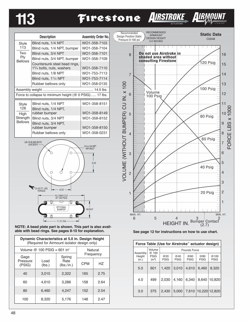
RecommendedDesign Position Static
Pressure 0-100 psi
48
6 5 4 3 2MAX. HT. MIN. HT.
16
15
14
13
12
11
10
9
8
7
6
5
4
3
2
1
100 Psig
80 Psig
40 Psig
20 Psig
60 Psig
120 Psig
8
7
6
5
4
3
2
1
Bumper Contact(2.7)
Volume100 Psig
Do not use Airstroke inshaded area withoutconsulting Firestone
RECOMMENDEDAIRMOUNT
DESIGN HEIGHT5.0 INCHES
Static DataC0248
HEIGHT IN.
113
HEIGHTOPTIONALBUMPER
15.2 MAX O.D.AT 100 PSIG
11.31 DIA.
3/8-16 BLIND NUTS(5/8 DEEP)
6.25
1/4 or 3/4 NPTAIR INLET
15-20 FT. LBS.TORQUE
6.25
NOTE: A bead plate part is shown. This part is also avail-able with bead rings. See pages 8-10 for explanation. See page 12 for instructions on how to use chart.
VOLUME(WITHO
UTBUMPER)CU
IN.x100
FORC
ELBSx1000
Dynamic Characteristics at 5.0 in. Design Height(Required for Airmount isolator design only)
Volume @ 100 PSIG = 601 in3
Gage SpringPressure Load Rate(PSIG) (lbs.) (lbs./ in.)
40 3,010 2,322 165 2.75
60 4,610 3,288 158 2.64
80 6,460 4,247 152 2.54
100 8,320 5,176 148 2.47
NaturalFrequency
CPM HZ
Description Assembly Order No.Blind nuts, 1/4 NPT WO1-358-7103Blind nuts, 1/4 NPT, bumper WO1-358-7104Blind nuts, 3/4 NPT WO1-358-7101Blind nuts, 3/4 NPT, bumper WO1-358-7109Countersunk steel bead rings,13/4 bolts, nuts, washers WO1-358-7110Blind nuts, 1/8 NPT WO1-753-7113Blind nuts, 11/4 NPT WO1-753-7114Rubber bellows only WO1-358-0135
Assembly weight ...................................................... 14.5 lbs.Force to collapse to minimum height (@ 0 PSIG)...... 17 lbs.
Style113
TwoPly
Bellows
Blind nuts, 1/4 NPT WO1-358-8151Blind nuts, 1/4 NPT,rubber bumper WO1-358-8149Blind nuts, 3/4 NPT WO1-358-8152Blind nuts, 3/4 NPT,rubber bumper WO1-358-8150Rubber bellows only WO1-358-0231
Style128
HighStrengthBellows
Force Table (Use for Airstroke™ actuator design)Volume Pounds Force
Assembly @ 100Height PSIG @20 @40 @60 @80 @100(in.) (in3) PSIG PSIG PSIG PSIG PSIG
5.0 601 1,420 3,010 4,610 6,460 8,320
4.0 499 2,030 4,160 6,340 8,640 10,820
3.0 375 2,430 5,000 7,610 10,220 12,820
RecommendedDesign Position Static
Pressure 0-100 psi

RecommendedDesign Position Static
Pressure 0-100 psi
Dynamic Characteristics at 5.5 in. Design Height(Required for Airmount isolator design only)
Volume @ 100 PSIG = 641 in3
Gage SpringPressure Load Rate(PSIG) (lbs.) (lbs./ in.)
40 3,820 2,198 142 2.37
60 5,900 3,091 136 2.26
80 7,990 3,986 133 2.21
100 10,200 4,923 130 2.17
NaturalFrequency
CPM HZ
7 6 5 4 3 2.1MAX. HT. MIN. HT.
18
17
16
15
14
13
12
11
10
9
8
7
6
5
4
3
2
1
80 Psig
20 Psig
60 Psig
9
8
7
6
5
4
3
2
1
Bumper Contact(2.7)
40 Psig
Do not use Airstroke inshaded area withoutconsulting Firestone
Volume100 Psig
100 Psig
120 Psig
RECOMMENDEDAIRMOUNT
DESIGN HEIGHT5.5 INCHES
Static DataC0281
HEIGHT IN.
113-1
49
HEIGHT
OPTIONALBUMPER
15.9 MAX O.D.AT 100 PSIG
11.31 DIA.
3/8-16 BLIND NUTS(5/8 DEEP)
6.25
1/4 or 3/4 NPTAIR INLET
15-20 FT. LBS.TORQUE
6.25
NOTE: A bead plate part is shown. This part is also avail-able with bead rings. See pages 8-10 for explanation. See page 12 for instructions on how to use chart.
VOLUME(WITHO
UTBUMPER)CU
IN.x100
FORC
ELBSx1000
Force Table (Use for Airstroke™ actuator design)Volume Pounds Force
Assembly @ 100Height PSIG @20 @40 @60 @80 @100(in.) (in3) PSIG PSIG PSIG PSIG PSIG
6.0 692 1,600 3,270 5,130 7,000 8,990
5.0 586 2,070 4,260 6,530 8,800 11,200
4.0 463 2,440 4,940 7,470 10,080 12,710
3.0 328 2,660 5,360 8,060 10,860 13,630
Style128-1High
StrengthBellows
Blind nuts, 1/4 NPT WO1-358-8161
Blind nuts, 3/4 NPT WO1-358-8160
Blind nuts, 3/4 NPT,rubber bumper WO1-358-8162
Description Assembly Order No.
Style113-1
TwoPly
Bellows
Blind nuts, 1/4 NPT WO1-358-7091
Blind nuts, 3/4 NPT WO1-358-7092
Blind nuts, 3/4 NPT, rubberbumper WO1-358-7094
Countersunk steel bead rings,1 3/4 bolts, nuts, washers WO1-358-7277
Rubber bellows only WO1-358-0150
Assembly weight ...................................................... 15.2 lbs.
Force to collapse to minimum height (@ 0 PSIG)...... 25 lbs.
RecommendedDesign Position Static
Pressure 0-100 psi

50
Force Table (Use for Airstroke™ actuator design)Volume Pounds Force
Assembly @ 100Height PSIG @20 @40 @60 @80 @100(in.) (in3) PSIG PSIG PSIG PSIG PSIG
8.0 1,169 425 1,260 2,566 4,038 5,636
7.0 1,094 1,423 3,210 5,194 7,334 9,528
6.0 981 2,140 4,564 7,048 9,682 12,385
5.0 840 2,676 5,476 8,458 11,440 14,471
4.0 679 3,051 6,153 9,478 12,738 15,965
3.0 510 3,219 6,609 10,069 13,550 17,218
9MAX. HT. MIN. HT.
8 7 6 5 3 2.5
14
13
12
11
10
9
8
7
6
5
4
3
2
1
0
4
Volume100 Psig
120 Psig
100 Psig
80 Psig
60 Psig
40 Psig
20 Psig
28
26
24
22
20
18
16
14
12
10
8
6
4
2
0
Do not use Airstroke inshaded area withoutconsulting Firestone
CONSULT FIRESTONEBEFORE USING AS
AIRMOUNT
RECOMMENDEDAIRMOUNT
DESIGN HEIGHT6.0 INCHES
Static DataB4561
HEIGHT IN.
153-2
HEIGHT
12.21 DIAMETER
6.253.12
3/8-16 BLIND NUTS(5/8 DEEP)
1/4 or 3/4 NPTAIR INLET
18.1 MAXIMUM O.D.AT 100 PSIG
15-20 FT. LBS.TORQUE
6.25
See page 12 for instructions on how to use chart.
VOLUME(WITHO
UTBUMPER)CU
IN.x100
FORC
ELBSx1000
Dynamic Characteristics at 6.0 in. Design Height(Required for Airmount isolator design only)
Volume @ 100 PSIG = 981 in3
Gage SpringPressure Load Rate(PSIG) (lbs.) (lbs./ in.)
40 4,564 2,202 131 2.18
60 7,048 3,153 126 2.10
80 9,682 4,031 121 2.02
100 12,385 4,958 119 1.98
NaturalFrequency
CPM HZ
NOTE: A bead plate part is shown. This part is also avail-able with bead rings. See pages 8-10 for explanation.
Description Assembly Order No.
Style153-2
TwoPly
Bellows
Blind nuts, 1/4 NPT WO1-358-8158
Blind nuts, 3/4 NPT WO1-358-8157
Ribbed neck aluminum beadbead rings (equal spacing) 17/8 bolts, nuts, washers
WO1-358-8165
Rubber bellows only WO1-358-1201
Assembly weight ...................................................... 17.1 lbs.
RecommendedDesign Position Static
Pressure 0-100 psi

RecommendedDesign Position Static
Pressure 0-100 psi
Dynamic Characteristics at 5.0 in. Design Height(Required for Airmount isolator design only)
Volume @ 100 PSIG = 787 in3
Gage SpringPressure Load Rate(PSIG) (lbs.) (lbs./ in.)
40 5,490 3,478 149 2.49
60 8,450 4,880 143 2.38
80 11,450 6,186 138 2.30
100 14,520 7,523 135 2.25
NaturalFrequency
CPM HZ
MAX. HT. MIN. HT.
7 6 5 4 3 2
Volume100 Psig
120 Psig
100 Psig
80 Psig
60 Psig
40 Psig
20 Psig
Do not use Airstroke inshaded area withoutconsulting Firestone
11
10
9
8
7
6
5
4
3
2
1
20
15
10
5
RECOMMENDEDAIRMOUNT
DESIGN HEIGHT5.0 INCHES
Static Data6948
HEIGHT IN.
119
51
HEIGHT
15.12 DIA.
18 (3/8-24) BOLTSEACH RING
28-32 FT. LBS.TORQUE
13.81 BOLT CIRCLE DIA.
17.4 MAX O.D.AT 100 PSIG
NOTE: A bead plate part is shown. This part is alsoavailable with rolled plates. See page 11 for explanation.
See page 12 for instructions on how to use chart.
VOLUME(WITHO
UTBUMPER)CU
IN.x100
FORC
ELBSx1000
Description Assembly Order No.Ribbed neck aluminumbead rings (equal spacing),17/8 bolts, nuts, washers WO1-358-7478Rubber bellows only WO1-358-0119Rolled Plate Assembly,1/2 blind nuts, 3/4 NPT WO1-358-7477
Assembly weight ...................................................... 13.2 lbs.Force to collapse to minimum height (@ 0 PSIG)...... 17 lbs.
Style119
TwoPly
Bellows
Force Table (Use for Airstroke™ actuator design)Volume Pounds Force
Assembly @ 100Height PSIG @20 @40 @60 @80 @100(in.) (in3) PSIG PSIG PSIG PSIG PSIG
6.0 932 1,640 3,800 6,100 8,550 11,070
5.0 787 2,560 5,490 8,450 11,450 14,520
4.0 617 3,080 6,470 9,850 13,190 16,600
3.0 436 3,310 6,920 10,530 14,030 17,630
RecommendedDesign Position Static
Pressure 0-100 psi
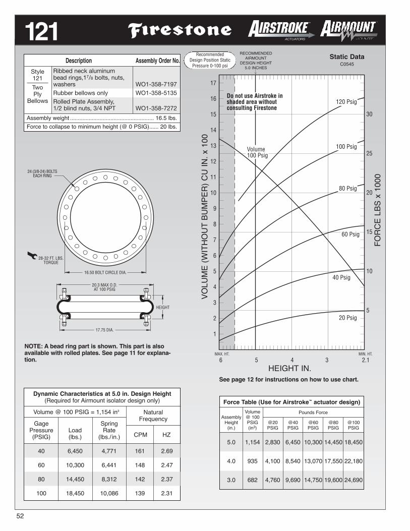
RecommendedDesign Position Static
Pressure 0-100 psi
52
6 5 4 3 2.1MAX. HT. MIN. HT.
30
25
20
15
10
5
100 Psig
80 Psig
40 Psig
20 Psig
120 Psig
Volume100 Psig
17
16
15
14
13
12
11
10
9
8
7
6
5
4
3
2
1
Do not use Airstroke inshaded area withoutconsulting Firestone
60 Psig
RECOMMENDEDAIRMOUNT
DESIGN HEIGHT5.0 INCHES
Static DataC0545
HEIGHT IN.
121
HEIGHT
17.75 DIA.
24 (3/8-24) BOLTSEACH RING
28-32 FT. LBS.TORQUE
16.50 BOLT CIRCLE DIA.
20.3 MAX O.D.AT 100 PSIG
NOTE: A bead ring part is shown. This part is alsoavailable with rolled plates. See page 11 for explana-tion.
See page 12 for instructions on how to use chart.
VOLUME(WITHO
UTBUMPER)CU
IN.x100
FORC
ELBSx1000
Dynamic Characteristics at 5.0 in. Design Height(Required for Airmount isolator design only)
Volume @ 100 PSIG = 1,154 in3
Gage SpringPressure Load Rate(PSIG) (lbs.) (lbs./ in.)
40 6,450 4,771 161 2.69
60 10,300 6,441 148 2.47
80 14,450 8,312 142 2.37
100 18,450 10,086 139 2.31
NaturalFrequency
CPM HZ
Description Assembly Order No.Ribbed neck aluminumbead rings,17/8 bolts, nuts,washers WO1-358-7197Rubber bellows only WO1-358-5135Rolled Plate Assembly,1/2 blind nuts, 3/4 NPT WO1-358-7272
Assembly weight ...................................................... 16.5 lbs.Force to collapse to minimum height (@ 0 PSIG)...... 20 lbs.
Style121
TwoPly
Bellows
Force Table (Use for Airstroke™ actuator design)Volume Pounds Force
Assembly @ 100Height PSIG @20 @40 @60 @80 @100(in.) (in3) PSIG PSIG PSIG PSIG PSIG
5.0 1,154 2,830 6,450 10,300 14,450 18,450
4.0 935 4,100 8,540 13,070 17,550 22,180
3.0 682 4,760 9,690 14,750 19,600 24,690
RecommendedDesign Position Static
Pressure 0-100 psi

RecommendedDesign Position Static
Pressure 0-100 psi
Dynamic Characteristics at 5.0 in. Design Height(Required for Airmount isolator design only)
Volume @ 100 PSIG = 1,315 in3
Gage SpringPressure Load Rate(PSIG) (lbs.) (lbs./ in.)
40 8,630 5,869 155 2.59
60 13,870 5,244 144 2.42
80 18,450 10,107 139 2.32
100 23,200 12,403 137 2.29
NaturalFrequency
CPM HZ
6 5 4 3 2MAX. HT. MIN. HT.
30
25
20
15
10
5
100 Psig
80 Psig
20 Psig
17
16
15
14
13
12
11
10
9
8
7
6
5
4
3
2
1
60 Psig
Volume100 Psig
40 Psig
Do not use Airstroke inshaded area withoutconsulting Firestone
RECOMMENDEDAIRMOUNT
DESIGN HEIGHT5.0 INCHES
Static DataC1805
HEIGHT IN.
126
53
HEIGHT
20.36 DIA.
24 (3/8-24) BOLTSEACH RING
28-32 FT. LBS.TORQUE
19.00 BOLT CIRCLE DIA.
22.4 MAX O.D.AT 100 PSIG
NOTE: A bead ring part is shown. This part is also avail-able with rolled plates. See page 11 for explanation.
See page 12 for instructions on how to use chart.
VOLUME(WITHO
UTBUMPER)CU
IN.x100
FORC
ELBSx1000
Description Assembly Order No.
Style126
TwoPly
Bellows
Ribbed neck aluminumbead rings (equal spacing),17/8 bolts, nuts, washers
WO1-358-7727
Rolled Plate Assembly,1/2 blind nuts, 3/4 NPT
WO1-358-7726
Rubber bellows only WO1-358-1026
Assembly weight ...................................................... 21.3 lbs.
Force to collapse to minimum height (@ 0 PSIG)...... 25 lbs.
Force Table (Use for Airstroke™ actuator design)
AssemblyHeight(in.)
Volume @100 PSIG(in3)
Pounds Force
@20PSIG
@40PSIG
@60PSIG
@80PSIG
@100PSIG
6.0 1,694 1,800 4,000 7,100 10,900 15,000
5.0 1,473 4,220 8,630 13,870 18,450 23,200
4.0 1,196 5,200 10,840 16,630 22,460 28,070
3.0 875 6,010 12,040 19,020 25,960 32,000
RecommendedDesign Position Static
Pressure 0-100 psi

RecommendedDesign Position Static
Pressure 0-100 psi
54
65
60
55
50
45
40
35
30
25
20
15
10
5
8 7 6 5 4 3 2.1MAX. HT. MIN. HT.
65
60
55
50
45
40
35
30
25
20
15
10
5
Volume100 Psig
Do not use Airstroke inshaded area withoutconsulting Firestone
20 Psig
40 Psig
60 Psig
80 Psig
100 Psig
120 Psig
RECOMMENDEDAIRMOUNT
DESIGN HEIGHT6.0 INCHES
Static DataB6172
HEIGHT IN.
HEIGHT
25.13 DIA.
32 (3/8-24) BOLTSEACH RING
28-32 FT. LBS.TORQUE
23.50 BOLT CIRCLE DIA.
27.9 MAX O.D.AT 100 PSIG
See page 12 for instructions on how to use chart.
VOLUMECU
IN.x100
FORC
ELBSx1000
Dynamic Characteristics at 6.0 in. Design Height(Required for Airmount isolator design only)
Volume @ 100 PSIG = 2,846 in3
Gage SpringPressure Load Rate(PSIG) (lbs.) (lbs./ in.)
40 15,020 6,932 128 2.13
60 23,040 10,353 125 2.10
80 31,240 12,979 121 2.02
100 39,570 15,786 119 1.98
NaturalFrequency
CPM HZ
138-1.5Description Assembly Order No.
Ribbed neck aluminumbead rings (equal spacing),17/8 bolts, nuts, washers WO1-358-7737Rubber bellows only
WO1-358-0147
Assembly weight ...................................................... 24.5 lbs.Force to collapse to minimum height (@ 0 PSIG).... 150 lbs.
Style138-1.5
Two PlyHigh
StrengthBellows
Force Table (Use for Airstroke™ actuator design)Volume Pounds Force
Assembly @ 100Height PSIG @20 @40 @60 @80 @100(in.) (in3) PSIG PSIG PSIG PSIG PSIG
7.0 3,227 5,290 10,830 17,450 24,320 31,630
6.0 2,846 7,290 15,020 23,040 31,240 39,570
5.0 2,402 8,610 17,220 26,410 35,580 44,680
4.0 1,906 9,760 19,630 29,320 39,260 49,620
3.0 1,376 10,200 20,840 31,560 41,930 53,010
RecommendedDesign Position Static
Pressure 0-100 psi

RecommendedDesign Position Static
Pressure 0-100 psi
Dynamic Characteristics at 5.5 in. Design Height(Required for Airmount isolator design only)
Volume @ 100 PSIG = 4,914 in3
Gage SpringPressure Load Rate(PSIG) (lbs.) (lbs./ in.)
40 32,860 14,220 123 2.06
60 50,290 19,969 118 1.97
80 67,690 26,697 118 1.96
100 85,200 32,491 116 1.93
NaturalFrequency
CPM HZ
8 7 6 5 4 3
125
120
115
110
105
100
95
90
85
80
75
70
65
60
55
50
45
40
35
30
25
20
15
10
5
MAX. HT. MIN. HT.
60
55
50
45
40
35
30
25
20
15
10
5
Volume100 Psig
20 Psig
40 Psig
60 Psig
80 Psig
100 Psig
2.5
Do not use Airstroke inshaded area withoutconsulting Firestone
120 Psig
RECOMMENDEDAIRMOUNT
DESIGN HEIGHT5.5 INCHES
Static Data8411
HEIGHT IN.
148-1
55
HEIGHT
35.04 DIA.
40 (3/8-24) BOLTSEACH RING
28-32 FT. LBS.TORQUE
32.68 BOLT CIRCLE DIA.
37.4 MAX O.D.AT 100 PSIG
NOTE: The effective length of the 1 7/8 bolt is 1.05” inthis bead ring. See page 12 for instructions on how to use chart.
VOLUME(WITHO
UTBUMPER)CU
IN.x100
FORC
ELBSx1000
Force Table (Use for Airstroke™ actuator design)Volume Pounds Force
Assembly @ 100Height PSIG @20 @40 @60 @80 @100(in.) (in3) PSIG PSIG PSIG PSIG PSIG
7.0 6,134 13,470 26,890 41,610 55,830 70,860
6.0 5,337 15,720 31,220 47,920 64,170 80,890
5.0 4,471 17,450 34,310 52,370 70,980 89,140
4.0 3,532 18,810 36,970 56,050 76,330 95,540
3.0 2,542 19,940 39,470 59,360 80,110 100,050
Description Assembly Order No.Style148-1
HighStrengthBellows
Ribbed neck aluminum beadrings (equal spacing), 17/8
bolts, nuts, washersWO1-358-9601
Rubber bellows only WO1-358-1021
Assembly weight ...................................................... 46.3 lbs.
Force to collapse to minimum height (@ 0 PSIG).... 310 lbs.
RecommendedDesign Position Static
Pressure 0-100 psi

RecommendedDesign Position Static
Pressure 0-100 psi
56
7 6 5 4MAX. HT. MIN. HT
22
21
20
19
18
17
16
15
14
13
12
11
10
9
8
7
6
5
4
3
2
1
11
10
9
8
7
6
5
4
3
2
1
3.0
60 Psig
40 Psig
20 Psig
Volume100 Psig
80 Psig
100 Psig
120 Psig
Do not use Airstroke inshaded area withoutconsulting Firestone
RECOMMENDEDAIRMOUNT
DESIGN HEIGHT5.5 INCHES
Static DataB7340
HEIGHT IN.
25
HEIGHT
3/8-16 BLIND NUTS(5/8 DEEP)
6.4 MAX O.D.AT 100 PSIG
1.75
4.50 DIA.
1/4 NPTAIR INLET
15-20 FT. LBS.TORQUE
NOTE: A bead plate part is shown. This part is alsoavailable with bead rings. Bolts are not included.See pages 8-10 for explanation.
See page 12 for instructions on how to use chart.
VOLUMECU
IN.x10
FORC
ELBSx100
Dynamic Characteristics at 5.5 in. Design Height(Required for Airmount isolator design only)
Volume @ 100 PSIG = 86 in3
Gage SpringPressure Load Rate(PSIG) (lbs.) (lbs./ in.)
40 515 339 153 2.54
60 787 482 147 2.45
80 1,062 634 145 2.42
100 1,360 773 141 2.36
NaturalFrequency
CPM HZ
Description Assembly Order No.Blind nuts, 1/4 NPT WO1-358-7025Blind nuts, 3/4 NPT WO1-358-7047Blind nuts, 1/4 NPT both ends WO1-358-70353/4 NPT both ends(no blind nuts) WO1-606-7025Socket head aluminum beadrings (bolts, nuts, washers notincluded, use cap screws) WO1-358-00303/4 NPT (only) upper plate,blind nuts lower plate WO1-358-7030Rubber bellows only WO1-358-0319
Assembly weight ........................................................ 3.8 lbs.Force to collapse to minimum height (@ 0 PSIG)...... 30 lbs.
Style25
TwoPly
Bellows
Force Table (Use for Airstroke™ actuator design)Volume Pounds Force
Assembly @ 100Height PSIG @20 @40 @60 @80 @100(in.) (in3) PSIG PSIG PSIG PSIG PSIG
5.0 78 300 590 890 1,210 1,540
4.0 60 380 720 1,080 1,450 1,810
3.0 39 420 800 1,220 1,640 2,060
RecommendedDesign Position Static
Pressure 0-100 psi

Dynamic Characteristics at 6.0 in. Design Height(Required for Airmount isolator design only)
Volume @ 100 PSIG = 100 in3
Gage SpringPressure Load Rate(PSIG) (lbs.) (lbs./ in.)
40 566 309 139 2.32
60 871 432 132 2.21
80 1,194 565 129 2.16
100 1,524 681 126 2.10
NaturalFrequency
CPM HZ
14
12
10
8
6
4
2
0
8MAX. HT.
MIN. HT.7 6 5 4 3
Volume100 Psig
28
24
20
16
12
8
4
0
20 Psig
120 PsigDo not use Airstroke inshaded area withoutconsulting Firestone
100 Psig
80 Psig
60 Psig
40 Psig
CONSULT FIRESTONEBEFORE USING AS
AIRMOUNT
RECOMMENDEDAIRMOUNT
DESIGN HEIGHT6.0 INCHES
Static DataC0769
HEIGHT IN.
255-1.5
57
6.4 MAX O.D.AT 100 PSIG
HEIGHT
4.50 DIA.
3/8-16 BLIND NUTS(5/8 DEEP) 1/4 NPT
AIR INLET
1.7515-20 FT. LBS.
TORQUE
NOTE: A bead plate part is shown. This part is alsoavailable with bead rings. Bolts are not included.See pages 8-10 for explanation.
See page 12 for instructions on how to use chart.
VOLUMECU
IN.x10
FORC
ELBSx100
Description Assembly Order No.Blind nuts, 1/4 NPT WO1-358-6955Blind nuts, 3/4 NPT WO1-358-6956Rubber bellows only WO1-358-0048Socket head aluminum bead WO1-358-6833rings (bolts, nuts, washersnot included, use cap screws)
Assembly weight ........................................................ 3.9 lbs.Force to collapse to minimum height (@ 0 PSIG)...... 50 lbs.
Style255-1.5
TwoPly
Bellows
Force Table (Use for Airstroke™ actuator design)Volume Pounds Force
Assembly @ 100Height PSIG @20 @40 @60 @80 @100(in.) (in3) PSIG PSIG PSIG PSIG PSIG
7.0 114 188 417 661 921 1,198
6.0 100 270 566 871 1,194 1,524
5.0 82 331 686 1,041 1,414 1,786
4.0 62 389 729 1,197 1,612 2,039
RecommendedDesign Position Static
Pressure 0-100 psi

RecommendedDesign Position Static
Pressure 0-100 psi
58
3
2
1
2
1
40 Psig
20 Psig
Volume100 Psig
80 Psig
100 Psig
120 PsigDo not use Airstroke inshaded area withoutconsulting Firestone
60 Psig
MIN. HT.MAX. HT.
9 8 7 6 5 4 3
RECOMMENDEDAIRMOUNT
DESIGN HEIGHT6.5 INCHES
Static DataB8955
HEIGHT IN.
224
HEIGHT
3/8-16 BLIND NUTS(5/8 DEEP)
8.0 MAX O.D.AT 100 PSIG
2.75
5.31 DIA.
1/4 NPTAIR INLET
15-20 FT. LBS.TORQUE
NOTE: A bead plate part is shown. This part is also avail-able with bead rings. See pages 8-10 for explanation.
See page 12 for instructions on how to use chart.
VOLUMECU
IN.x100
FORC
ELBSx1000
Dynamic Characteristics at 6.5 in. Design Height(Required for Airmount isolator design only)
Volume @ 100 PSIG = 171 in3
Gage SpringPressure Load Rate(PSIG) (lbs.) (lbs./ in.)
40 730 361 132 2.20
60 1,130 523 128 2.13
80 1,530 690 126 2.10
100 1,940 849 124 2.07
NaturalFrequency
CPM HZ
Description Assembly Order No.Blind nuts, 1/4 NPT WO1-358-3400Blind nuts, 3/4 NPT WO1-358-3403Countersunk steel bead rings,13/4 bolts, nuts, washers, WO1-358-3407
Assembly weight ........................................................ 5.0 lbs.Force to collapse to minimum height (@ 0 PSIG)...... 14 lbs.
Style224
TwoPly
Bellows
Force Table (Use for Airstroke™ actuator design)Volume Pounds Force
Assembly @ 100Height PSIG @20 @40 @60 @80 @100(in.) (in3) PSIG PSIG PSIG PSIG PSIG
7.0 181 320 630 990 1,340 1,710
6.0 160 400 820 1,260 1,700 2,160
5.0 134 470 960 1,490 2,040 2,570
4.0 105 550 1,110 1,720 2,310 2,930
3.0 73 590 1,210 1,860 2,480 3,150
RecommendedDesign Position Static
Pressure 0-100 psi

RecommendedDesign Position Static
Pressure 0-100 psi
Dynamic Characteristics at 8.0 in. Design Height(Required for Airmount isolator design only)
Volume @ 100 PSIG = 246 in3
Gage SpringPressure Load Rate(PSIG) (lbs.) (lbs./ in.)
40 590 348 144 2.41
60 980 451 128 2.13
80 1,360 589 123 2.04
100 1,780 732 121 2.01
NaturalFrequency
CPM HZ
10 9 8 7 6 5 4 3MAX. HT. MIN. HT.
3
2
1
Volume100 Psig
4 4
3
2
1
60 Psig
80 Psig
100 Psig
120 Psig
40 Psig
20 Psig
Do not use Airstroke inshaded area withoutconsulting Firestone
RECOMMENDEDAIRMOUNT
DESIGN HEIGHT8.0 INCHES
Static DataB6633
HEIGHT IN.
26
59
HEIGHT
3/8-16 BLIND NUTS(5/8 DEEP)
8.6 MAX O.D.AT 100 PSIG
2.75
5.31 DIA.
1/4 NPTAIR INLET
15-20 FT. LBS.TORQUE
NOTE: A bead plate part is shown. This part is also avail-able with bead rings. See pages 8-10 for explanation.
See page 12 for instructions on how to use chart.
VOLUMECU
IN.x100
FORC
ELBSx1000
Description Assembly Order No.Blind nuts, 1/4 NPT WO1-358-7325Blind nuts, 3/4 NPT WO1-358-7327Countersunk steel bead rings,13/4 bolts, nuts, washers WO1-358-7333Rubber bellows only WO1-358-0142
Assembly weight ........................................................ 5.3 lbs.Force to collapse to minimum height (@ 0 PSIG)...... 23 lbs.
Style26
TwoPly
Bellows
Force Table (Use for Airstroke™ actuator design)Volume Pounds Force
Assembly @ 100Height PSIG @20 @40 @60 @80 @100(in.) (in3) PSIG PSIG PSIG PSIG PSIG
8.0 246 270 590 980 1,360 1,780
7.0 233 390 810 1,270 1,740 2,240
6.0 196 480 1,010 1,530 2,060 2,630
5.0 164 570 1,180 1,780 2,420 3,110
4.0 128 660 1,340 2,010 2,750 3,510
RecommendedDesign Position Static
Pressure 0-100 psi

RecommendedDesign Position Static
Pressure 0-100 psi
MAX. HT. MIN. HT.
6
5
4
3
2
1
6
5
4
3
2
1
60 Psig
80 Psig
100 Psig
20 Psig
Do not use Airstroke inshaded area withoutconsulting Firestone
120 Psig
40 Psig
Volume100 Psig
11 10 9 8 7 6 5 4 3.1Bumper Contact
(4.2)
RECOMMENDEDAIRMOUNT
DESIGN HEIGHT8.5 INCHES
Static DataC0683
HEIGHT IN.
20
HEIGHT
OPTIONALBUMPER
*(1.50 FOR 3/4)
3/8-16 BLIND NUTS(5/8 DEEP)
9.9 MAX O.D.AT 100 PSIG
1.75*
6.31 DIA.
1/4 OR 3/4 NPTAIR INLET
15-20 FT. LBS.TORQUE
3.50
NOTE: A bead plate part is shown. This part is also avail-able with bead rings. See pages 8-10 for explanation. See page 12 for instructions on how to use chart.
VOLUME(WITHO
UTBUMPER)CU
IN.x100
FORC
ELBSx1000
Dynamic Characteristics at 8.5 in. Design Height(Required for Airmount isolator design only)
Volume @ 100 PSIG = 376 in3
Gage SpringPressure Load Rate(PSIG) (lbs.) (lbs./ in.)
40 990 414 121 2.02
60 1,540 615 119 1.98
80 2,130 820 116 1.94
100 2,720 996 114 1.89
NaturalFrequency
CPM HZ
Description Assembly Order No.Blind nuts, 1/4 NPT WO1-358-6910Blind nuts, 1/4 NPT, bumper WO1-358-6911Blind nuts, 3/4 NPT WO1-358-6900Blind nuts, 3/4 NPT, bumper WO1-358-6901Countersunk steel bead rings,13/4 bolts, nuts, washers WO1-358-6923Rubber bellows only WO1-358-0138
Assembly weight ........................................................ 7.5 lbs.Force to collapse to minimum height (@ 0 PSIG)...... 14 lbs.
Style20
TwoPly
Bellows
Blind nuts, 1/4 NPT WO1-358-7080Blind nuts, 3/4 NPT WO1-358-7119Rubber bellows only WO1-358-0237
Style202High
StrengthBellows
Force Table (Use for Airstroke™ actuator design)Volume Pounds Force
Assembly @ 100Height PSIG @20 @40 @60 @80 @100(in.) (in3) PSIG PSIG PSIG PSIG PSIG
9.0 390 420 850 1,330 1,850 2,380
8.0 360 550 1,120 1,730 2,390 3,030
7.0 325 660 1,330 2,090 2,830 3,570
6.0 284 760 1,520 2,390 3,180 4,030
5.0 239 840 1,680 2,610 3,510 4,430
4.0 190 920 1,830 2,810 3,790 4,790
60

Force Table (Use for Airstroke™ actuator design)Volume Pounds Force
Assembly @ 100Height PSIG @20 @40 @60 @80 @100(in.) (in3) PSIG PSIG PSIG PSIG PSIG
11.0 520 449 951 1,517 2,122 2,75310.0 488 572 1,184 1,848 2,531 3,2389.0 451 673 1,384 2134 2,880 3,6618.0 409 759 1,554 2,377 3,193 4,0497.0 364 836 1,704 2,590 3,485 4,4166.0 316 907 1,845 2,786 3,753 4,7485.0 256 975 1,979 2,954 3,968 5,005
Dynamic Characteristics at 10.0 in. Design HeightConsult factory before using as an Airmount isolator.
Volume @ 100 PSIG = 488 in3
Gage SpringPressure Load Rate(PSIG) (lbs.) (lbs./ in.)
40 1,184 376 106 1.77
60 1,848 534 101 1.68
80 2,531 669 97 1.61
100 3,238 813 94 1.57
NaturalFrequency
CPM HZ
60
50
40
30
20
10
0
13Bumper Contact
(4.2)
MAX. HT. MIN. HT.11 9 7 5 3
60
50
40
30
20
10
0
Volume100 Psig
80 Psig
20 Psig
60 Psig
100 Psig
120 Psig
Do not use Airstroke inshaded area withoutconsulting Firestone
40 Psig
CONSULT FIRESTONEBEFORE USING AS
AIRMOUNT
RECOMMENDEDAIRMOUNT
DESIGN HEIGHT10.0 INCHES
Static DataB9120
HEIGHT IN.
20-2
61
10.4 MAX O.D.AT 100 PSIG
HEIGHT
6.31 DIA.
3/8-16 BLIND NUTS(5/8 DEEP) 1/4 OR 3/4 NPT
AIR INLET
3.5015-20 FT. LBS.TORQUE
1.75*
OPTIONALBUMPER
*(1.50 FOR 3/4)
NOTE: The bellows extends beyond the bead plates atminimum heightNOTE: A bead plate part is shown. This part is also avail-able with bead rings. See pages 8-10 for explanation. See page 12 for instructions on how to use chart.
VOLUME(WITHOUT
BUMPER)CU
IN.x10
FORCELBSx100
Description Assembly Order No.
Style20-2
TwoPly
Bellows
Blind nuts, 1/4 NPT WO1-358-6951
Blind nuts, 1/4 NPT,rubber bumper WO1-358-6947
Blind nuts, 3/4 NPT WO1-358-6952
Countersunk steel bead rings,1 3/4 bolts, nuts, washers WO1-358-7789
Rubber bellows only WO1-358-0305
Assembly weight ........................................................ 7.7 lbs.
Force to collapse to minimum height (@ 0 PSIG).......17 lbs.
RecommendedDesign Position Static
Pressure 0-100 psi

RecommendedDesign Position Static
Pressure 0-100 psi
62
Description Assembly Order No.Blind nuts, 1/4 NPT WO1-358-7180Blind nuts, 1/4 NPT, bumper WO1-358-7400Blind nuts, 3/4 NPT WO1-358-7184Blind nuts, 3/4 NPT, bumper WO1-358-7185Countersunk steel bead rings,15/8 bolts, nuts, washers WO1-358-7431Rubber bellows only WO1-358-0226
Assembly weight ....................................................... 12.3 lbsForce to collapse to minimum height (@ 0 PSIG)...... 20 lbs.
MAX. HT. MIN. HT.
11
10
9
8
7
6
5
4
3
2
1
80 Psig
100 Psig
20 Psig
Do not use Airstroke inshaded area withoutconsulting Firestone
Volume100 Psig
12 11 10Bumper Contact
(4.2)
11
10
9
8
7
6
5
4
3
2
1
120 Psig
40 Psig
60 Psig
9 8 7 6 5 4 3.2
RECOMMENDEDAIRMOUNT
DESIGN HEIGHT9.5 INCHES
Static DataC1004
HEIGHT IN.
22
HEIGHT
OPTIONALBUMPER
3/8-16 BLIND NUTS(5/8 DEEP)
12.9 MAX O.D.AT 100 PSIG
6.20
9.00 DIA.
1/4 OR 3/4 NPTAIR INLET
15-20 FT. LBS.TORQUE
2.88
NOTE: A bead plate part is shown. This part is also avail-able with bead rings. See pages 8-10 for explanation. See page 12 for instructions on how to use chart.
VOLUME(WITHOUT
BUMPER)CU
IN.x100
FORCELBSx1000
Style22
TwoPly
Bellows
Blind nuts, 1/4 NPT WO1-358-7251Blind nuts, 1/4 NPT, bumper WO1-358-7291Blind nuts, 3/4 NPT WO1-358-7250Countersunk steel bead rings,13/4 bolts, nuts, washers WO1-358-7258Rubber bellows only WO1-358-7928
Style210
HighStrengthBellows
Dynamic Characteristics at 9.5 in. Design Height(Required for Airmount isolator design only)
Volume @ 100 PSIG = 782 in3
Gage SpringPressure Load Rate(PSIG) (lbs.) (lbs./ in.)
40 2,050 729 112 1.86
60 3,170 1,036 107 1.79
80 4,280 1,373 106 1.77
100 5,400 1,668 104 1.74
NaturalFrequency
CPM HZ
Force Table (Use for Airstroke™ actuator design)Volume Pounds Force
Assembly @ 100Height PSIG @20 @40 @60 @80 @100(in.) (in3) PSIG PSIG PSIG PSIG PSIG
10.0 809 950 1,810 2,830 3,810 4,8409.0 752 1,170 2,260 3,460 4,670 5,8808.0 685 1,310 2,590 3,940 5,350 6,7007.0 610 1,430 2,900 4,390 5,950 7,4506.0 529 1,540 3,170 4,780 6,470 8,1105.0 442 1,640 3,380 5,100 6,880 8,6304.0 349 1,730 3,520 5,340 7,180 9,020
RecommendedDesign Position Static
Pressure 0-100 psi

RecommendedDesign Position Static
Pressure 0-100 psi
Dynamic Characteristics at 10.5 in. Design Height(Required for Airmount isolator design only)
Volume @ 100 PSIG = 935 in3
Gage SpringPressure Load Rate(PSIG) (lbs.) (lbs./ in.)
40 1,930 684 112 1.86
60 3,030 999 108 1.80
80 4,130 1,319 106 1.77
100 5,310 1,630 104 1.73
NaturalFrequency
CPM HZ
MAX. HT. MIN. HT.
12
1
0
9
8
7
6
5
4
3
2
1
80 Psig
100 Psig
20 Psig
13 12 11 10Bumper Contact
(4.2)
120 Psig
40 Psig
60 Psig
Do not use Airstroke inshaded area withoutconsulting Firestone
12
11
10
9
8
7
6
5
4
3
2
1
9 8 7 6 5 4 3
Volume100 Psig
RECOMMENDEDAIRMOUNT
DESIGN HEIGHT10.5 INCHES
Static DataB5297
HEIGHT IN.
22-1.5
63
HEIGHT
OPTIONALBUMPER
3/8-16 BLIND NUTS(5/8 DEEP)
13.7 MAX O.D.AT 100 PSIG
6.20
1/4 OR 3/4 NPTAIR INLET
15-20 FT. LBS.TORQUE
2.88
9.00 DIA.
See page 12 for instructions on how to use chart.
VOLUME(WITHOUT
BUMPER)CU
IN.x100
FORCELBSx1000
Force Table (Use for Airstroke™ actuator design)Volume Pounds Force
Assembly @ 100Height PSIG @20 @40 @60 @80 @100(in.) (in3) PSIG PSIG PSIG PSIG PSIG
10.0 905 1,040 2,140 3,340 4,550 5,8309.0 838 1,220 2,520 3,880 5,250 6,7008.0 763 1,370 2,850 4,360 5,850 7,4507.0 681 1,510 3,150 4,810 6,430 8,1706.0 591 1,650 3,400 5,210 6,990 8,8605.0 496 1,760 3,590 5,520 7,420 9,3804.0 396 1,840 3,730 5,730 7,680 9,700
NOTE: A bead plate part is shown. This part is alsoavailable with bead rings. See pages 8-10 for explanation.
NOTE: The bellows extends beyond the bead plates atminimum height.
Description Assembly Order No.
Style22-1.5
TwoPly
Bellows
Blind nuts, 1/4 NPT WO1-358-7444Blind nuts, 1/4 NPT,rubber bumper WO1-358-7473
Blind nuts, 3/4 NPT WO1-358-7442Blind nuts, 1/4 NPT(centered) WO1-358-7443Rubber bellows only WO1-358-0259Countersunk steel bead rings,1 5/8 bolts, nuts, washers WO1-358-7480
Assembly weight ...................................................... 12.9 lbs.Force to collapse to minimum height (@ 0 PSIG)...... 26 lbs.
RecommendedDesign Position Static
Pressure 0-100 psi

RecommendedDesign Position Static
Pressure 0-100 psi
64
MAX. HT. MIN. HT.
16
15
14
13
12
11
10
9
8
7
6
5
4
3
2
1
80 Psig
12 11 10Bumper Contact
(4.8)
120 Psig
40 Psig
60 Psig
Do not use Airstroke inshaded area withoutconsulting Firestone
9 8 7 6 5 4 3.2
Volume100 Psig
16
15
14
13
12
11
10
9
8
7
6
5
4
3
2
1
100 Psig
20 Psig
RECOMMENDEDAIRMOUNT
DESIGN HEIGHT9.5 INCHES
Static DataB9108
HEIGHT IN.
21
HEIGHT
OPTIONALBUMPER
3/8-16 BLIND NUTS(5/8 DEEP)
15.1 MAX O.D.AT 100 PSIG
6.25
11.31 DIA.
1/4 OR 3/4 NPTAIR INLET
15-20 FT. LBS.TORQUE 6.25
See page 12 for instructions on how to use chart.
VOLUME(WITHOUT
BUMPER)CU
IN.x100
FORCELBSx1000
Dynamic Characteristics at 9.5 in. Design Height(Required for Airmount isolator design only)
Volume @ 100 PSIG = 1,136 in3
Gage SpringPressure Load Rate(PSIG) (lbs.) (lbs./ in.)
40 3,030 1,110 114 1.89
60 4,750 1,582 108 1.80
80 6,540 2,044 105 1.75
100 8,330 2,500 103 1.71
NaturalFrequency
CPM HZ
Force Table (Use for Airstroke™ actuator design)Volume Pounds Force
Assembly @ 100Height PSIG @20 @40 @60 @80 @100(in.) (in3) PSIG PSIG PSIG PSIG PSIG
10.0 1,180 1,260 2,670 4,240 5,890 7,5509.0 1,091 1,590 3,330 5,180 7,100 9,0108.0 989 1,810 3,800 5,850 7,980 10,1207.0 878 2,000 4,180 6,400 8,700 11,0206.0 758 2,160 4,490 6,860 9,310 11,7605.0 630 2,300 4,760 7,260 9,830 12,4004.0 497 2,440 5,010 7,620 10,300 12,960
Description Assembly Order No.Blind nuts, 1/4 NPT WO1-358-7145Blind nuts, 1/4 NPT, bumper WO1-358-7146Blind nuts, 3/4 NPT WO1-358-7143Blind nuts, 3/4 NPT, bumper WO1-358-7144Countersunk steel bead rings,13/4 bolts, nuts, washers WO1-358-7139Rubber bellows only WO1-358-0213
Assembly weight ....................................................... 17.3 lbsForce to collapse to minimum height (@ 0 PSIG)...... 22 lbs.
Style21
TwoPly
Bellows
Blind nuts, 1/4 NPT WO1-358-7208Blind nuts, 1/4 NPT, bumper WO1-358-7221Blind nuts, 3/4 NPT WO1-358-7224Countersunk steel bead rings,13/4 bolts, nuts, washers WO1-358-7237Rubber bellows only WO1-358-7929
Style205
HighStrengthBellows
NOTE: A bead plate part is shown. This part is alsoavailable with bead rings. See pages 8-10 for explanation.
RecommendedDesign Position Static
Pressure 0-100 psi

RecommendedDesign Position Static
Pressure 0-100 psi
Force Table (Use for Airstroke™ actuator design)Volume Pounds Force
Assembly @ 100Height PSIG @20 @40 @60 @80 @100(in.) (in3) PSIG PSIG PSIG PSIG PSIG
11.0 1,510 1,540 3,180 4,930 6,730 8,55010.0 1,410 1,810 3,710 5,730 7,760 9,7909.0 1,298 2,040 4,150 6,430 8,570 10,7808.0 1,177 2,240 4,530 7,050 9,290 11,6907.0 1,048 2,400 4,850 7,570 10,030 12,6206.0 910 2,530 5,140 8,000 10,670 13,4405.0 764 2,620 5,370 8,310 11,100 13,9904.0 615 2,690 5,490 8,490 11,330 14,280
Dynamic Characteristics at 10.5 in. Design Height(Required for Airmount isolator design only)
Volume @ 100 PSIG = 1,462 in3
Gage SpringPressure Load Rate(PSIG) (lbs.) (lbs./ in.)
40 3,460 989 100 1.67
60 5,350 1,437 97 1.62
80 7,280 1,850 95 1.58
100 9,210 2,247 93 1.55
NaturalFrequency
CPM HZ
MAX. HT. MIN. HT.
18
17
16
15
14
13
12
11
10
9
8
7
6
5
4
3
2
1
80 Psig
100 Psig
14 12 10Bumper Contact
(4.8)
120 Psig
8 6 4 3.0
18
17
16
15
14
13
12
11
10
9
8
7
6
5
4
3
2
1
Do not use Airstroke inshaded area withoutconsulting Firestone
Volume100 Psig
40 Psig
60 Psig
20 Psig
RECOMMENDEDAIRMOUNT
DESIGN HEIGHT10.5 INCHES
Static DataB5315
HEIGHT IN.
21-2
65
HEIGHT
OPTIONALBUMPER
3/8-16 BLIND NUTS(5/8 DEEP)
16.0 MAX O.D.AT 100 PSIG
6.25
11.31 DIA.
15-20 FT. LBS.TORQUE 6.25
1/4 OR 3/4 NPTAIR INLET
See page 12 for instructions on how to use chart.
VOLUME(WITHOUT
BUMPER)CU
IN.x100
FORCELBSx1000
NOTE: A bead plate part is shown. This part is alsoavailable with bead rings. See pages 8-10 for explanation.
NOTE: The bellows extends beyond the bead plates atminimum height.
Description Assembly Order No.
Style21-2
TwoPly
Bellows
Blind nuts, 1/4 NPT WO1-358-6800
Blind nuts, 1/4 NPT, rubberbumper WO1-358-6801
Blind nuts, 3/4 NPT WO1-358-9529
Countersunk steel bead rings,1 7/8 bolts, nuts, washers WO1-358-9531
Assembly weight ....................................................... 18.2 lbs
Force to collapse to minimum height (@ 0 PSIG)...... 35 lbs.
RecommendedDesign Position Static
Pressure 0-100 psi

RecommendedDesign Position Static
Pressure 0-100 psi
66
Force Table (Use for Airstroke™ actuator design)Volume Pounds Force
Assembly @ 100Height PSIG @20 @40 @60 @80 @100(in.) (in3) PSIG PSIG PSIG PSIG PSIG
12.0 1,548 1,542 3,299 5,184 7,194 9,321
10.0 1,333 1,992 4,052 6,239 8,483 10,937
8.0 1,091 2,311 4,666 7,128 9,601 12,333
6.0 829 2,569 5,174 7,485 10,564 13,468
4.0 556 2,793 5,431 8,189 10,966 13,867
20
18
16
14
12
10
8
6
4
2
0
16 14 12 10 8 6 4Bumper Contact
(4.8)
120 Psig
100 Psig
80 Psig
60 Psig
40 Psig
20 Psig
Volume100 Psig
Do not use Airstroke inshaded area withoutconsulting Firestone
20
18
16
14
12
10
8
6
4
2
0MAX. HT. MIN. HT.
3
CONSULT FIRESTONEBEFORE USING AS
AIRMOUNT
RECOMMENDEDAIRMOUNT
DESIGN HEIGHT11.25 INCHES
HEIGHT IN.
233-2
15.5 MAX O.D.AT 100 PSIG
HEIGHT
11.31 DIA.
3/8-16 BLIND NUTS(5/8 DEEP)
1/4 NPTAIR INLET
6.25
3.125
6.25
OPTIONALBUMPER
15-20 FT. LBS.TORQUE
See page 12 for instructions on how to use chart.
VOLUME(WITHOUT
BUMPER)CU
IN.x100
FORCELBSx1000
Dynamic Characteristics at 11.25 in. Design Height(Required for Airmount isolator design only)
Volume @ 100 PSIG = 1,418 in3
Gage SpringPressure Load Rate(PSIG) (lbs.) (lbs./ in.)
40 3,413 968 100 1.67
60 5,631 1,351 92 1.53
80 7,691 1,735 89 1.49
100 9,917 2,122 87 1.45
NaturalFrequency
CPM HZ
NOTE: A bead plate part is shown. This part is also avail-able with bead rings. See pages 8-10 for explanation.
NOTE: The bellows extends beyond the bead plates atminimum height.
Static DataB5316
Description Assembly Order No.
Style233-2
TwoPly
Bellows
Blind nuts, 1/4 NPT WO1-358-6810
Blind nuts, 1/4 NPT, rubberbumper WO1-358-7781
Blind nuts, 3/4 NPT WO1-358-6811
Blind nuts, 3/4 NPT, rubberbumper WO1-358-6819
Countersunk steel bead rings,1 7/8 bolts, nuts, washers WO1-358-7558
Assembly weight ....................................................... 19.6 lbs
Force to collapse to minimum height (@ 0 PSIG).... 100 lbs.
RecommendedDesign Position Static
Pressure 0-100 psi

RecommendedDesign Position Static
Pressure 0-100 psi
Dynamic Characteristics at 9.5 in. Design Height(Required for Airmount isolator design only)
Volume @ 100 PSIG = 1,596 in3
Gage SpringPressure Load Rate(PSIG) (lbs.) (lbs./ in.)
40 4,590 1,553 109 1.82
60 7,010 2,125 103 1.72
80 9,590 2,779 101 1.68
100 12,120 3,471 100 1.67
NaturalFrequency
CPM HZ
MAX. HT. MIN. HT.
25
24
23
22
21
20
19
18
17
16
15
14
13
12
11
10
9
8
7
6
5
4
3
2
1
80 Psig
Do not use Airstroke inshaded area withoutconsulting Firestone
Volume100 Psig
60 Psig
20 Psig
25
20
15
10
5
12 11 10 9 8 7 6 5 4 3.4
40 Psig
120 Psig
100 Psig
RECOMMENDEDAIRMOUNT
DESIGN HEIGHT9.5 INCHES
Static DataB6040
HEIGHT IN.
28
67
HEIGHT
15.12 DIA.
18 (3/8-24) BOLTSEACH RING
13.81 BOLT CIRCLE DIA.
17.4 MAX O.D.AT 100 PSIG
28-32 FT. LBS.TORQUE
NOTE: A bead ring part is shown. This part is alsoavailable with rolled plates. See page 11 for explana-tion.
See page 12 for instructions on how to use chart.
VOLUME(WITHOUT
BUMPER)CU
IN.x100
FORCELBSx1000
Description Assembly Order No.Ribbed neck aluminum beadrings (equal spacing),17/8 bolts, nuts, washers WO1-358-7191Ribbed neck aluminum beadrings (unequal spacing) 17/8 b,n,w WO1-358-7194Ribbed neck aluminum beadrings (equal spacing) 11/4 b,n,w WO1-358-7192Rolled plate assembly, 1/2blind nut 3/4 NPT WO1-358-7271Rubber bellows only WO1-358-7925
Assembly weight ....................................................... 19.0 lbsForce to collapse to minimum height (@ 0 PSIG)...... 38 lbs.
Style28
TwoPly
Bellows
Ribbed neck aluminum beadrings (equal spacing) WO1-358-7244Rubber Bellows Only WO1-139-0201
Style 201High
StrengthBellows
Force Table (Use for Airstroke™ actuator design)Volume Pounds Force
Assembly @ 100Height PSIG @20 @40 @60 @80 @100(in.) (in3) PSIG PSIG PSIG PSIG PSIG
10.0 1,658 2,090 4,150 6,410 8,780 11,1009.0 1,529 2,500 5,000 7,550 10,290 13,0108.0 1,384 2,840 5,700 8,530 11,530 14,5507.0 1,224 3,110 6,250 9,340 12,580 15,7906.0 1,053 3,330 6,650 9,940 13,380 16,7605.0 871 3,590 7,130 10,690 14,380 18,0104.0 679 3,820 7,570 11,360 15,270 19,130
RecommendedDesign Position Static
Pressure 0-100 psi

RecommendedDesign Position Static
Pressure 0-100 psi
68
MAX. HT. MIN. HT.
3534333231302928272625242322212019181716151413121110987654321
80 Psig
Do not use Airstroke inshaded area withoutconsulting Firestone
Volume100 Psig
20 Psig
12 11 10 9 8 7 6 5 4 3.5
40 Psig
120 Psig
100 Psig
35
30
25
20
15
10
5
1
60 Psig
RECOMMENDEDAIRMOUNT
DESIGN HEIGHT9.5 INCHES
Static DataB6265
HEIGHT IN.
203
HEIGHT
17.75 DIA.
24 (3/8-24) BOLTSEACH RING
16.50 BOLT CIRCLE DIA.
20.0 MAX O.D.AT 100 PSIG
28-32 FT. LBS.TORQUE
NOTE: A bead ring part is shown. This part is also avail-able with rolled plates. See page 11 for explanation. See page 12 for instructions on how to use chart.
VOLUME(WITHOUT
BUMPER)CU
IN.x100
FORCELBSx1000
Dynamic Characteristics at 9.5 in. Design Height(Required for Airmount isolator design only)
Volume @ 100 PSIG = 2,163 in3
Gage SpringPressure Load Rate(PSIG) (lbs.) (lbs./ in.)
40 7,210 2,190 103 1.72
60 11,100 3,150 100 1.67
80 14,970 4,040 97 1.62
100 18,890 4,971 96 1.60
NaturalFrequency
CPM HZ
Description Assembly Order No.Ribbed neck aluminum beadrings (equal spacing),17/8 bolts, nuts, washers WO1-358-7227Ribbed neck aluminum beadrings (equal spacing) 11/4 b,n,w WO1-358-7225Rolled plate assembly, 1/2blind nut 3/4 NPT WO1-358-7273Rubber bellows only WO1-358-0205
Assembly weight ....................................................... 23.8 lbsForce to collapse to minimum height (@ 0 PSIG)...... 40 lbs.
Style203
TwoPly
Bellows
Ribbed neck aluminum beadrings (equal spacing)17/8 bolts, nuts, washers WO1-358-7228
Style 218High
StrengthBellows
Force Table (Use for Airstroke™ actuator design)Volume Pounds Force
Assembly @ 100Height PSIG @20 @40 @60 @80 @100(in.) (in3) PSIG PSIG PSIG PSIG PSIG
10.0 2,261 3,330 6,710 10,340 14,000 17,6809.0 2,067 3,820 7,680 11,780 15,850 19,9708.0 1,853 4,210 8,450 12,880 17,370 21,8407.0 1,625 4,520 9,010 13,700 18,590 23,2806.0 1,385 4,790 9,510 14,460 19,490 24,3605.0 1,135 5,070 10,140 15,380 20,580 25,7904.0 870 5,350 10,760 16,260 21,750 27,240
RecommendedDesign Position Static
Pressure 0-100 psi

RecommendedDesign Position Static
Pressure 0-100 psi
Dynamic Characteristics at 9.5 in. Design Height(Required for Airmount isolator design only)
Volume @ 100 PSIG = 2,934 in3
Gage SpringPressure Load Rate(PSIG) (lbs.) (lbs./ in.)
40 9,780 2,752 96 1.60
60 14,860 3,737 94 1.57
80 20,060 4,844 92 1.54
100 25,350 5,917 91 1.51
NaturalFrequency
CPM HZ
MAX. HT. MIN. HT.
40
35
30
25
20
15
10
5
Do not use Airstroke inshaded area withoutconsulting Firestone
Volume100 Psig
13 12 11 10 9 8 7 6 5 4 3.3
40
35
30
25
20
15
10
5
80 Psig
60 Psig
20 Psig
40 Psig
120 Psig
100 Psig
RECOMMENDEDAIRMOUNT
DESIGN HEIGHT9.5 INCHES
Static Data5532
HEIGHT IN.
29
69
HEIGHT
20.36 DIA.
24 (3/8-24) BOLTSEACH RING
19.00 BOLT CIRCLE DIA.
22.7 MAX O.D.AT 100 PSIG
28-32 FT. LBS.TORQUE
NOTE: A bead ring part is shown. This part is alsoavailable with rolled plates. See page 11 for explanation See page 12 for instructions on how to use chart.
VOLUME(WITHOUT
BUMPER)CU
IN.x100
FORCELBSx1000
Description Assembly Order No.Ribbed neck aluminum beadrings (equal spacing),17/8 bolts, nuts, washers WO1-358-7203Ribbed neck aluminum beadrings (unequal spacing) 17/8 b,n,w WO1-358-7205Ribbed neck aluminum beadrings (equal spacing) 11/4 b,n,w WO1-358-7201Rolled plate assembly,1/2blind nuts 3/4 NPT WO1-358-7275Rubber bellows only WO1-358-7902
Assembly weight ....................................................... 28.8 lbsForce to collapse to minimum height (@ 0 PSIG)...... 70 lbs.
Style29
TwoPly
Bellows
Ribbed neck aluminum beadrings (equal spacing),17/8 bolts, nuts, washers WO1-358-7242Ribbed neck aluminum beadrings (unequal spacing) 17/8 b,n,w WO1-358-7239Rubber bellows only WO1-139-0207
Style207
HighStrengthBellows
Force Table (Use for Airstroke™ actuator design)Volume Pounds Force
Assembly @ 100Height PSIG @20 @40 @60 @80 @100(in.) (in3) PSIG PSIG PSIG PSIG PSIG
10.0 3,064 4,480 9,320 14,130 19,110 24,1909.0 2,796 4,990 10,200 15,520 20,940 26,4108.0 2,512 5,440 10,990 16,680 22,480 28,2707.0 2,206 5,780 11,650 17,620 23,740 29,8306.0 1,889 5,950 12,090 18,330 24,640 31,0005.0 1,559 6,310 12,720 19,340 26,040 32,7404.0 1,211 6,650 13,320 20,150 27,140 34,100
RecommendedDesign Position Static
Pressure 0-100 psi
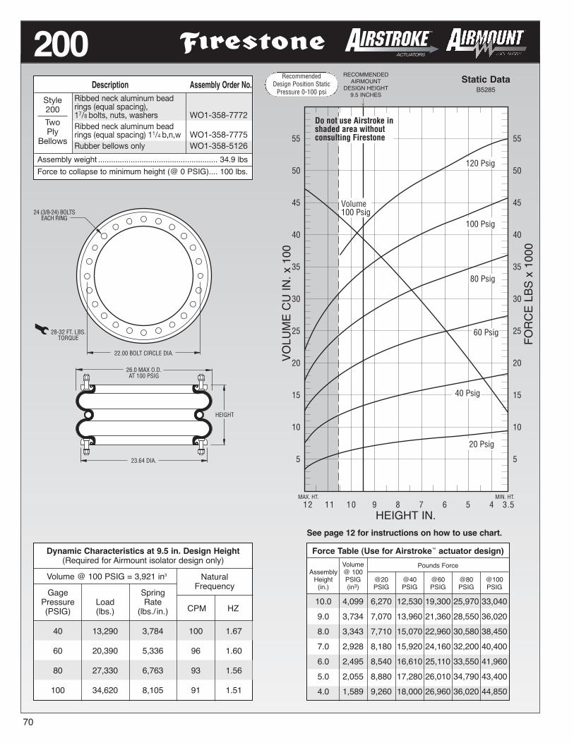
RecommendedDesign Position Static
Pressure 0-100 psi
70
MAX. HT. MIN. HT.
55
50
45
40
35
30
25
20
15
10
5
Do not use Airstroke inshaded area withoutconsulting Firestone
Volume100 Psig
12 11 10 9 8 7 6 5 4 3.5
80 Psig
20 Psig
40 Psig
120 Psig
100 Psig
55
50
45
40
35
30
25
20
15
10
5
60 Psig
RECOMMENDEDAIRMOUNT
DESIGN HEIGHT9.5 INCHES
Static DataB5285
HEIGHT IN.
200
HEIGHT
23.64 DIA.
24 (3/8-24) BOLTSEACH RING
22.00 BOLT CIRCLE DIA.
26.0 MAX O.D.AT 100 PSIG
28-32 FT. LBS.TORQUE
See page 12 for instructions on how to use chart.
VOLUMECU
IN.x100
FORCELBSx1000
Dynamic Characteristics at 9.5 in. Design Height(Required for Airmount isolator design only)
Volume @ 100 PSIG = 3,921 in3
Gage SpringPressure Load Rate(PSIG) (lbs.) (lbs./ in.)
40 13,290 3,784 100 1.67
60 20,390 5,336 96 1.60
80 27,330 6,763 93 1.56
100 34,620 8,105 91 1.51
NaturalFrequency
CPM HZ
Description Assembly Order No.Ribbed neck aluminum beadrings (equal spacing),17/8 bolts, nuts, washers WO1-358-7772Ribbed neck aluminum beadrings (equal spacing) 11/4 b,n,w WO1-358-7775Rubber bellows only WO1-358-5126
Assembly weight ....................................................... 34.9 lbsForce to collapse to minimum height (@ 0 PSIG).... 100 lbs.
Style200
TwoPly
Bellows
Force Table (Use for Airstroke™ actuator design)Volume Pounds Force
Assembly @ 100Height PSIG @20 @40 @60 @80 @100(in.) (in3) PSIG PSIG PSIG PSIG PSIG
10.0 4,099 6,270 12,530 19,300 25,970 33,0409.0 3,734 7,070 13,960 21,360 28,550 36,0208.0 3,343 7,710 15,070 22,960 30,580 38,4507.0 2,928 8,180 15,920 24,160 32,200 40,4006.0 2,495 8,540 16,610 25,110 33,550 41,9605.0 2,055 8,880 17,280 26,010 34,790 43,4004.0 1,589 9,260 18,000 26,960 36,020 44,850
RecommendedDesign Position Static
Pressure 0-100 psi

RecommendedDesign Position Static
Pressure 0-100 psi
Force Table (Use for Airstroke™ actuator design)Volume Pounds Force
Assembly @ 100Height PSIG @20 @40 @60 @80 @100(in.) (in3) PSIG PSIG PSIG PSIG PSIG
12.0 5,701 6,520 13,310 20,720 28,410 36,100
10.0 4,882 8,170 16,480 25,050 33,720 42,350
8.0 3,964 9,120 18,460 27,920 37,570 47,010
6.0 2,973 9,910 19,940 30,070 40,430 51,100
4.0 1,907 10,790 21,290 31,970 42,980 54,390
Dynamic Characteristics at 10.5 in. Design Height(Required for Airmount isolator design only)
Volume @ 100 PSIG = 5,094 in3
Gage SpringPressure Load Rate(PSIG) (lbs.) (lbs./ in.)
40 15,840 3,858 93 1.54
60 24,140 5,370 88 1.47
80 32,550 6,857 86 1.44
100 40,980 8,203 84 1.40
NaturalFrequency
CPM HZ
MAX. HT. MIN. HT.
65
60
55
50
45
40
35
30
25
20
15
10
5
Do not use Airstroke inshaded area withoutconsulting Firestone
14 12 10 8 6 3.5
80 Psig
20 Psig
40 Psig
100 Psig
60 Psig
65
60
55
50
45
40
35
30
25
20
15
10
5
120 Psig
Volume100 Psig
RECOMMENDEDAIRMOUNT
DESIGN HEIGHT10.5 INCHES
Static DataB5936
HEIGHT IN.
215
71
HEIGHT
25.13 DIA.
32 (3/8-24) BOLTSEACH RING
23.50 BOLT CIRCLE DIA.
27.9 MAX O.D.AT 100 PSIG
28-32 FT. LBS.TORQUE
See page 12 for instructions on how to use chart.
VOLUMECU
IN.x100
FORCELBSx1000
Description Assembly Order No.Ribbed neck aluminum beadrings (equal spacing),17/8 bolts, nuts, washers WO1-358-7230Ribbed neck aluminum beadrings (unequal spacing) 17/8 b,n,w WO1-358-7301Ribbed neck aluminum beadrings (equal spacing) 11/4 b,n,w WO1-358-7302Rubber bellows only WO1-358-7912
Assembly weight . . . . . . . . . . . . . . . . . . . . . . . . . . 38.4 lbs.Force to collapse to minimum height (@ 0 PSIG).... 160 lbs.
Style215
Two PlyHigh
StrengthBellows
RecommendedDesign Position Static
Pressure 0-100 psi

RecommendedDesign Position Static
Pressure 0-100 psi
72
Description Assembly Order No.Ribbed neck aluminum beadrings (equal spacing),17/8 bolts, nuts, washers WO1-358-9602
Assembly weight ...................................................... 72.5 lbs.Force to collapse to minimum height (@ 0 PSIG).... 350 lbs.
10
5
16 14 12 10 8 6 4.2
120 Psig
100 Psig
80 Psig
20 Psig
MAX. HT. MIN. HT.
Do not use Airstroke inshaded area withoutconsulting Firestone
Volume100 Psig
40 Psig
125
120
115
110
105
100
95
90
85
80
75
70
65
60
55
50
45
40
35
30
25
20
15
10
5
60 Psig
RECOMMENDEDAIRMOUNT
DESIGN HEIGHT11.0 INCHES
Static Data8412
HEIGHT IN.
248-2
HEIGHT
35.04 DIA.
40 (3/8-24) BOLTSEACH RING
32.68 BOLT CIRCLE DIA.
37.4 MAX O.D.AT 100 PSIG
28-32 FT. LBS.TORQUE
NOTE: The effective length of 17/8 bolt is 1.05” in thisbead ring. See page 12 for instructions on how to use chart.
VOLUMECU
IN.x1000
FORCELBSx1000
Style248-2
FourPly
Bellows
Dynamic Characteristics at 11.0 in. Design Height(Required for Airmount isolator design only)
Volume @ 100 PSIG = 9,815 in3
Gage SpringPressure Load Rate(PSIG) (lbs.) (lbs./ in.)
40 30,830 6,746 88 1.46
60 47,720 9,549 84 1.40
80 63,890 12,423 83 1.38
100 79,730 14,989 81 1.36
NaturalFrequency
CPM HZ
Force Table (Use for Airstroke™ actuator design)Volume Pounds Force
Assembly @ 100Height PSIG @20 @40 @60 @80 @100(in.) (in3) PSIG PSIG PSIG PSIG PSIG
13.0 11,386 12,660 26,460 41,020 55,290 69,700
11.0 9,815 15,200 30,830 47,720 63,890 79,730
9.0 8,090 16,890 34,210 52,080 69,850 87,790
7.0 6,243 18,210 37,030 55,570 74,410 93,230
5.0 4,304 19,270 38,820 58,730 78,570 98,180
RecommendedDesign Position Static
Pressure 0-100 psi

Dynamic Characteristics at 13.5 in. Design Height(Required for Airmount isolator design only)
Volume @ 100 PSIG = 1,168 in3
Gage SpringPressure Load Rate(PSIG) (lbs.) (lbs./ in.)
40 2,319 475 85 1.42
60 3,631 675 81 1.35
80 5,017 851 77 1.29
100 6,463 1,042 75 1.26
Description Assembly Order No.Blind nuts, 1/4 NPT WO1-358-8048Blind nuts, 3/4 NPT WO1-358-8047
Assembly weight ...................................................... 20.3 lbs.Force to collapse to minimum height (@ 0 PSIG).... 200 lbs.
NaturalFrequency
CPM HZ
16
14
12
10
8
6
4
2
0
19MAX. HT. MIN. HT. 4.8"
17 15 13 11 9 7 5
20 Psig
80 Psig
100 Psig
120 Psig
60 Psig
16
14
12
10
8
6
4
2
0
Volume100 Psig
40 Psig
Do not use Airstroke inshaded area withoutconsulting Firestone
CONSULT FIRESTONEBEFORE USING AS
AIRMOUNT
RECOMMENDEDAIRMOUNT
DESIGN HEIGHT13.5 INCHES
Static DataB8940
HEIGHT IN.
352
73
13.1 MAX O.D.AT 100 PSIG
HEIGHT
10.40 DIA.
15-20 FT. LBS.TORQUE
OPTIONALBUMPER
3/8-16 BLIND NUTS(5/8 DEEP) 1/4 OR 3/4 NPT
AIR INLET
6.20
2.88
See page 12 for instructions on how to use chart.
VOLUME(WITHOUT
BUMPER)CU
IN.x100
FORCELBSx1000
Style352
TwoPly
Bellows
Force Table (Use for Airstroke™ actuator design)Volume Pounds Force
Assembly @ 100Height PSIG @20 @40 @60 @80 @100(in.) (in3) PSIG PSIG PSIG PSIG PSIG
16.0 1,330 679 1,695 2,780 4,000 5,22114.0 1,203 1,015 2,211 3,480 4,838 6,24812.0 1,057 1,278 2,622 4,068 5,557 7,10410.0 892 1,497 3,025 4,662 6,365 8,0698.0 708 1,700 3,457 5,296 7,201 9,1276.0 507 1,917 3,896 5,910 7,881 10,0305.0 400 2,040 4,095 6,169 8,165 10,363
NOTE: A bead plate part is shown. This part is also avail-able with bead rings. See pages 8-10 for explanation.
RecommendedDesign Position Static
Pressure 0-100 psi
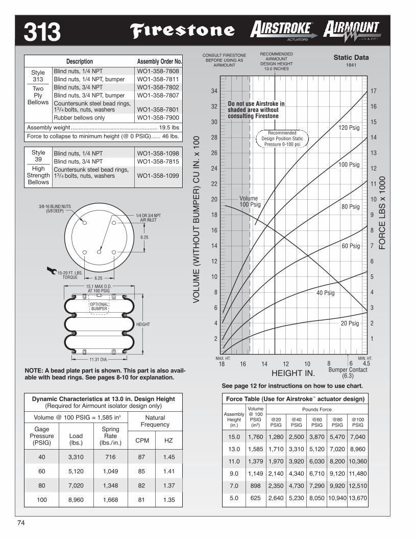
74
Force Table (Use for Airstroke™ actuator design)Volume Pounds Force
Assembly @ 100Height PSIG @20 @40 @60 @80 @100(in.) (in3) PSIG PSIG PSIG PSIG PSIG
15.0 1,760 1,280 2,500 3,870 5,470 7,040
13.0 1,585 1,710 3,310 5,120 7,020 8,960
11.0 1,379 1,970 3,920 6,030 8,200 10,360
9.0 1,149 2,140 4,340 6,710 9,120 11,480
7.0 898 2,350 4,730 7,290 9,920 12,510
5.0 625 2,640 5,230 8,050 10,940 13,670
MAX. HT. MIN. HT.
34
32
30
28
26
24
22
20
18
16
14
12
10
8
6
4
2
80 Psig
8 6Bumper Contact
(6.3)
40 Psig
60 Psig
17
16
15
14
13
12
11
10
9
8
7
6
5
4
3
2
1
18 16 14 12 10 4.5
120 Psig
100 Psig
20 Psig
Volume100 Psig
Do not use Airstroke inshaded area withoutconsulting Firestone
CONSULT FIRESTONEBEFORE USING AS
AIRMOUNT
RECOMMENDEDAIRMOUNT
DESIGN HEIGHT13.0 INCHES
Static Data1841
HEIGHT IN.
313
HEIGHT
OPTIONALBUMPER
15.1 MAX O.D.AT 100 PSIG
11.31 DIA.
3/8-16 BLIND NUTS(5/8 DEEP)
6.25
15-20 FT. LBS.TORQUE 6.25
1/4 OR 3/4 NPTAIR INLET
See page 12 for instructions on how to use chart.
VOLUME(WITHOUT
BUMPER)CU
IN.x100
FORCELBSx1000
Dynamic Characteristics at 13.0 in. Design Height(Required for Airmount isolator design only)
Volume @ 100 PSIG = 1,585 in3
Gage SpringPressure Load Rate(PSIG) (lbs.) (lbs./ in.)
40 3,310 716 87 1.45
60 5,120 1,049 85 1.41
80 7,020 1,348 82 1.37
100 8,960 1,668 81 1.35
NaturalFrequency
CPM HZ
Description Assembly Order No.Blind nuts, 1/4 NPT WO1-358-7808Blind nuts, 1/4 NPT, bumper WO1-358-7811Blind nuts, 3/4 NPT WO1-358-7802Blind nuts, 3/4 NPT, bumper WO1-358-7807Countersunk steel bead rings,13/4 bolts, nuts, washers WO1-358-7801Rubber bellows only WO1-358-7900
Assembly weight ....................................................... 19.5 lbsForce to collapse to minimum height (@ 0 PSIG)...... 46 lbs.
Style313
TwoPly
Bellows
Blind nuts, 1/4 NPT WO1-358-1098Blind nuts, 3/4 NPT WO1-358-7815Countersunk steel bead rings,13/4 bolts, nuts, washers WO1-358-1099
Style39
HighStrengthBellows
NOTE: A bead plate part is shown. This part is also avail-able with bead rings. See pages 8-10 for explanation.
RecommendedDesign Position Static
Pressure 0-100 psi

Dynamic Characteristics at 14.70 in. Design Height(Required for Airmount isolator design only)
Volume @ 100 PSIG = 1,786 in3
Gage SpringPressure Load Rate(PSIG) (lbs.) (lbs./ in.)
40 3,282 685 86 1.43
60 5,167 933 80 1.33
80 7,000 1,179 77 1.28
100 8,940 1,425 75 1.25
Description Assembly Order No.Blind nuts, 1/4 NPT WO1-358-7845Blind nuts, 1/4 NPT, bumper WO1-358-7838Blind nuts, 3/4 NPT WO1-358-7842Blind nuts, 3/4 NPT, bumper WO1-358-7849Countersunk steel bead ring13/4 bolts, nuts, washers WO1-358-7830Rubber bellows only WO1-358-7019
Assembly weight ...................................................... 24.6 lbs.Force to collapse to minimum height (@ 0 PSIG)...... 65 lbs.
NaturalFrequency
CPM HZ
22
20
18
16
14
12
10
8
6
4
2
0
20 18 16 14 12 10 8 6Bumper Contact
(4.75)
MAX. HT. MIN. HT.
22
20
18
16
14
12
10
8
6
4
2
0
Do not use Airstroke inshaded area withoutconsulting Firestone
Volume100 Psig
4.5
120 Psig
100 Psig
80 Psig
20 Psig
60 Psig
40 Psig
CONSULT FIRESTONEBEFORE USING AS
AIRMOUNT
RECOMMENDEDAIRMOUNT
DESIGN HEIGHT14.7 INCHES
Static Data8695
HEIGHT IN.
333
75
3.125
15.2 MAX O.D.AT 100 PSIG
HEIGHT
6.25
6.25
11.31 DIA.
1/4 NPTAIR INLET
3/8-16 BLIND NUTS(5/8 DEEP)
OPTIONALBUMPER
NOTE: A bead plate part is shown. This part is also avail-able with bead rings. See pages 8-10 for explanation.
See page 12 for instructions on how to use chart.
VOLUME(WITHOUT
BUMPER)CU
IN.x100
FORCELBSx1000
Style333
TwoPly
Bellows
Force Table (Use for Airstroke™ actuator design)Volume Pounds Force
Assembly @ 100Height PSIG @20 @40 @60 @80 @100(in.) (in3) PSIG PSIG PSIG PSIG PSIG
16.0 1,904 1,338 2,866 4,524 6,241 8,06214.0 1,718 1,706 3,478 5,388 7,325 9,33812.0 1,507 1,981 3,955 6,083 8,200 10,40510.0 1,274 2,208 4,376 6,698 9,003 11,4008.0 1,022 2,389 4,733 7,220 9,710 12,2786.0 754 2,574 5,087 7,724 10,396 13,1394.0 473 3,049 5,871 8,787 11,827 14,918
RecommendedDesign Position Static
Pressure 0-100 psi

76
Force Table (Use for Airstroke™ actuator design)Volume Pounds Force
Assembly @ 100Height PSIG @20 @40 @60 @80 @100(in.) (in3) PSIG PSIG PSIG PSIG PSIG
14.0 2,342 2,300 4,640 7,230 9,820 12,420
12.0 2,061 2,760 5,510 8,560 11,510 14,450
10.0 1,744 3,130 6,260 9,620 12,870 16,060
8.0 1,400 3,340 6,940 10,370 13,820 17,440
6.0 1,021 3,790 7,580 11,510 15,350 19,280
18 16 14 12 10MAX. HT. MIN. HT.
26
25
24
23
22
21
20
19
18
17
16
15
14
13
12
11
10
9
8
7
6
5
4
3
2
1
4.5
20 Psig
26
20
15
10
5
Volume100 Psig
40 Psig
100 Psig
120 Psig
80 Psig
60 Psig
Do not use Airstroke inshaded area withoutconsulting Firestone
8 6
CONSULT FIRESTONEBEFORE USING AS
AIRMOUNT
RECOMMENDEDAIRMOUNT
DESIGN HEIGHT13.0 INCHES
Static Data1909
HEIGHT IN.
312
HEIGHT
15.12 DIA.
18 (3/8-24) BOLTSEACH RING
28-32 FT. LBS.TORQUE
13.81 BOLT CIRCLE DIA.
18.2 MAX O.D.AT 100 PSIG
NOTE: A bead ring part is shown. This part is alsoavailable with rolled plates. See page 11 for explana-tion.
See page 12 for instructions on how to use chart.
VOLUME(WITHOUT
BUMPER)CU
IN.x100
FORCELBSx1000
Dynamic Characteristics at 13.0 in. Design Height(Required for Airmount isolator design only)
Volume @ 100 PSIG = 2,207 in3
Gage SpringPressure Load Rate(PSIG) (lbs.) (lbs./ in.)
40 5,100 1,056 85 1.42
60 7,930 1,536 83 1.38
80 10,730 1,950 80 1.33
100 13,530 2,371 79 1.31
NaturalFrequency
CPM HZ
Description Assembly Order No.Ribbed neck aluminum beadrings (equal spacing),17/8 bolts, nuts, washers WO1-358-7761Ribbed neck aluminum beadrings (unequal spacing) 17/8 b,n,w WO1-358-7760Rolled plate assembly, 1/2blind nuts, 3/4 NPT WO1-358-7286Rubber bellows only WO1-358-7914
Assembly weight ....................................................... 24.8 lbsForce to collapse to minimum height (@ 0 PSIG).... 135 lbs.
Style312
TwoPly
Bellows
Ribbed neck aluminum beadrings (equal spacing),17/8 bolts, nuts, washers WO1-358-8003Ribbed neck aluminum beadrings (unequal spacing) 17/8 b,n,w WO1-358-8004Rolled plate assembly, 1/2blind nuts, 3/4 NPT WO1-358-8009Rubber bellows only WO1-358-7926
Style314
HighStrengthBellows
RecommendedDesign Position Static
Pressure 0-100 psi

Force Table (Use for Airstroke™ actuator design)Volume Pounds Force
Assembly @ 100Height PSIG @20 @40 @60 @80 @100(in.) (in3) PSIG PSIG PSIG PSIG PSIG
15.0 3,470 3,220 6,640 10,280 13,960 17,740
13.0 3,073 3,960 8,010 12,030 16,270 20,580
11.0 2,632 4,330 8,910 13,420 18,030 22,770
9.0 2,150 4,740 9,610 14,450 19,410 24,420
7.0 1,639 5,030 10,120 15,410 20,770 26,200
5.0 1,093 5,610 11,140 16,590 22,380 28,170
Dynamic Characteristics at 13.0 in. Design Height(Required for Airmount isolator design only)
Volume @ 100 PSIG = 3,073 in3
Gage SpringPressure Load Rate(PSIG) (lbs.) (lbs./ in.)
40 8,010 1,744 88 1.46
60 12,030 2,104 78 1.31
80 16,270 2,784 78 1.30
100 20,580 3,624 79 1.31
NaturalFrequency
CPM HZ
18 16 14 12 10MAX. HT. MIN. HT.
35
30
25
20
15
10
5
Volume100 Psig
40 Psig
100 Psig
120 Psig
80 Psig
60 Psig
Do not use Airstroke inshaded area withoutconsulting Firestone
8 6 4.6
35
30
25
20
15
10
520 Psig
CONSULT FIRESTONEBEFORE USING AS
AIRMOUNT
RECOMMENDEDAIRMOUNT
DESIGN HEIGHT13.0 INCHES
Static DataB5385
HEIGHT IN.
323
77
HEIGHT
17.75 DIA.
24 (3/8-24) BOLTSEACH RING
28-32 FT. LBS.TORQUE
16.50 BOLT CIRCLE DIA.
20.5 MAX O.D.AT 100 PSIG
NOTE: A bead ring part is shown. This part is also avail-able with rolled plates. See page 11 for explanation. See page 12 for instructions on how to use chart.
VOLUME(WITHOUT
BUMPER)CU
IN.x100
FORCELBSx1000
Description Assembly Order No.Ribbed neck aluminum beadrings (equal spacing),17/8 bolts, nuts, washers WO1-358-7823Rolled plate assembly, 1/2blind nuts, 3/4 NPT WO1-358-7274Rubber bellows only WO1-358-7921
Assembly weight ....................................................... 31.1 lbsForce to collapse to minimum height (@ 0 PSIG)...... 70 lbs.
Style323
TwoPly
Bellows
Ribbed neck aluminum beadrings (equal spacing),17/8 bolts, nuts, washers WO1-358-7829Rubber bellows only WO1-358-0324
Style324
HighStrengthBellows
RecommendedDesign Position Static
Pressure 0-100 psi

78
19 17 15 13 11MAX. HT MIN. HT.
45
40
35
30
25
20
15
10
5
0
90
80
70
60
50
40
30
20
10
0
9 7 4 . 5
Do not use Airstroke inshaded area withoutconsulting Firestone
120 Psig
100 Psig
80 Psig
60 Psig
40 Psig
20 Psig
Volume100 Psig
CONSULT FIRESTONEBEFORE USING AS
AIRMOUNT
RECOMMENDEDAIRMOUNT
DESIGN HEIGHT14.0 INCHES
Static DataC1801
HEIGHT IN.
320
HEIGHT
20.36 DIA.
24 (3/8-24) BOLTSEACH RING
28-32 FT. LBS.TORQUE
19.00 BOLT CIRCLE DIA.
22.4 MAX O.D.AT 100 PSIG
NOTE: A bead ring part is shown. This part is alsoavailable with rolled plates. See page 11 for explana-tion.
See page 12 for instructions on how to use chart.
VOLUME(WITHOUT
BUMPER)CU
IN.x100
FORCELBSx1000
Dynamic Characteristics at 14.0 in. Design Height(Required for Airmount isolator design only)
Volume @ 100 PSIG = 4,263 in3
Gage SpringPressure Load Rate(PSIG) (lbs.) (lbs./ in.)
40 9,340 1,588 77 1.29
60 14,250 2,515 79 1.32
80 19,200 3,114 76 1.26
100 24,220 3,724 74 1.23
NaturalFrequency
CPM HZ
Description Assembly Order No.Ribbed neck aluminum beadrings (equal spacing),17/8 bolts, nuts, washers WO1-358-7324Rolled plate assembly, 1/2blind nuts, 3/4 NPT WO1-358-7276Rubber bellows only WO1-358-0987
Assembly weight ....................................................... 36.3 lbsForce to collapse to minimum height (@ 0 PSIG)...... 90 lbs.
Style320
TwoPly
Bellows
Style328
HighStrengthBellows
Ribbed neck aluminum beadrings (equal spacing),17/8 bolts, nuts, washers WO1-358-9528Rolled plate assembly, 1/2blind nuts, 3/4 NPT WO1-358-9526
Force Table (Use for Airstroke™ actuator design)
AssemblyHeight(in.)
Volume @100 PSIG(in3)
Pounds Force
@20PSIG
@40PSIG
@60PSIG
@80PSIG
@100PSIG
16.0 4,754 3,730 7,930 11,990 16,370 21,230
14.0 4,263 4,450 9,340 14,250 19,200 24,220
12.0 3,716 5,230 10,470 15,700 21,260 26,980
10.0 3,122 5,860 11,420 17,220 23,580 29,680
8.0 2,495 5,940 12,020 18,170 24,700 31,120
6.0 1,819 6,210 13,150 20,030 26,890 33,870
RecommendedDesign Position Static
Pressure 0-100 psi

Dynamic Characteristics at 15.0 in. Design Height(Required for Airmount isolator design only)
Volume @ 100 PSIG = 6,984 in3
Gage SpringPressure Load Rate(PSIG) (lbs.) (lbs./ in.)
40 15,080 2,731 80 1.34
60 23,220 3,602 74 1.23
80 31,160 4,554 72 1.20
100 39,070 5,532 71 1.18
NaturalFrequency
CPM HZ
130
120
110
100
90
80
70
60
50
40
30
20
10
0
20 18 16 14 12 10MAX. HT. MIN. HT.
65
60
55
50
45
40
35
30
25
20
15
10
5
0
8 6 4 . 5
Do not use Airstroke inshaded area withoutconsulting Firestone
120 Psig
100 Psig
80 Psig
60 Psig
20 Psig
40 Psig
Volume100 Psig
CONSULT FIRESTONEBEFORE USING AS
AIRMOUNT
RECOMMENDEDAIRMOUNT
DESIGN HEIGHT15.0 INCHES
Static DataB6252
HEIGHT IN.
321
79
HEIGHT
25.13 DIA.
32 (3/8-24) BOLTSEACH RING
28-32 FT. LBS.TORQUE
23.50 BOLT CIRCLE DIA.
27.9 MAX O.D.AT 100 PSIG
See page 12 for instructions on how to use chart.
VOLUMECU
IN.x100
FORCELBSx1000
Force Table (Use for Airstroke™ actuator design)Volume Pounds Force
Assembly @ 100Height PSIG @20 @40 @60 @80 @100(in.) (in3) PSIG PSIG PSIG PSIG PSIG
18.0 8,136 5,300 11,230 17,840 24,760 31,66016.0 7,390 6,830 13,920 21,490 29,220 37,01014.0 6,560 7,830 15,890 24,130 32,390 40,83012.0 5,660 8,230 17,080 25,960 34,870 44,06010.0 4,711 8,950 18,220 27,640 36,450 46,3708.0 3,717 9,250 19,030 29,160 39,320 49,2706.0 2,653 10,100 20,350 31,200 41,890 52,170
Description Assembly Order No.Ribbed neck aluminum beadrings (equal spacing),17/8 bolts, nuts, washers WO1-358-7304Ribbed neck aluminum beadrings (unequal spacing) 17/8 b,n,w WO1-358-7306Rubber bellows only WO1-358-7919
Assembly weight ....................................................... 51.3 lbsForce to collapse to minimum height (@ 0 PSIG).... 180 lbs.
Style321
Two PlyHigh
StrengthBellows
RecommendedDesign Position Static
Pressure 0-100 psi

80
25
24
23
22
21
20
19
18
17
16
15
14
13
12
11
10
9
8
7
6
5
4
3
2
1
0
23 21 19 17 15 13 11MAX. HT. MIN. HT.
125
120
115
110
105
100
95
90
85
80
75
70
65
60
55
50
45
40
35
30
25
20
15
10
5
0
9 7 5 . 5
120 Psig
100 Psig
80 Psig
60 Psig
40 Psig
20 Psig
Do not use Airstroke inshaded area withoutconsulting Firestone
Volume100 Psig
CONSULT FIRESTONEBEFORE USING AS
AIRMOUNT
RECOMMENDEDAIRMOUNT
DESIGN HEIGHT15.0 INCHES
Static Data8413
HEIGHT IN.
348-3
HEIGHT
35.04 DIA.
40 (3/8-24) BOLTSEACH RING
28-32 FT. LBS.TORQUE
32.68 BOLT CIRCLE DIA.
37.4 MAX O.D.AT 100 PSIG
NOTE: The effective length of the 17/8 bolt is 1.05” inthis bead ring. See page 12 for instructions on how to use chart.
VOLUMECU
IN.x1000
FORCELBSx1000
Dynamic Characteristics at 15.0 in. Design Height(Required for Airmount isolator design only)
Volume @ 100 PSIG = 13,501 in3
Gage SpringPressure Load Rate(PSIG) (lbs.) (lbs./ in.)
40 31,480 4,761 73 1.22
60 47,870 6,586 70 1.16
80 64,870 8,614 68 1.14
100 82,540 10,592 67 1.12
NaturalFrequency
CPM HZ
Description Assembly Order No.Ribbed neck aluminum beadrings (equal spacing),17/8 bolts, nuts, washers WO1-358-9603Rubber bellows only WO1-358-1023
Assembly weight ..................................................... 103.9 lbsForce to collapse to minimum height (@ 0 PSIG).... 380 lbs.
Style348-3
HighStrengthBellows
Force Table (Use for Airstroke™ actuator design)Volume Pounds Force
Assembly @ 100Height PSIG @20 @40 @60 @80 @100(in.) (in3) PSIG PSIG PSIG PSIG PSIG
18.0 15,946 14,080 27,430 43,790 57,710 74,67016.0 14,340 15,190 30,370 46,420 62,810 80,19014.0 12,634 16,230 32,380 49,170 66,610 84,82012.0 10,843 17,330 33,880 51,470 69,410 89,15010.0 8,984 18,290 35,370 53,580 71,930 93,0308.0 7,075 19,070 36,970 55,590 74,740 96,4706.0 5,102 19,760 38,620 57,550 77,790 99,680
RecommendedDesign Position Static
Pressure 0-100 psi

RecommendedDesign Position Static
Pressure 0-100 psiDescription Assembly Order No.
Thin wall assembly,without cap WO1-358-9188Thin wall assembly,with cap (dotted line) WO1-358-9190Thin wall rubber bellowsonly WO1-358-0480
Assembly weight ........................................................ 2.6 lbs.
NOTE:Do not use as an Airstroke actuator.
1 2 1 1 1 0MAX. HT. MIN. HT.
11
10
9
8
7
6
5
4
3
2
1
0
9 8 7 6 5
11
10
9
8
7
6
5
4
3
2
1
0
80 Psig
60 Psig
40 Psig
20 Psig
Volume80 Psig
AIRMOUNT ISOLATOR ONLY RECOMMENDEDAIRMOUNT
DESIGN HEIGHT8.0 INCHES
Static DataR9260
HEIGHT IN.
1X84D-1
81
HEIGHT
TOP VIEW SHOWNWITHOUT CAP
(OPTIONAL CAP)
USE 1/4" CAP SCREWS(INCLUDED WITH CAP
ASSEMBLY ONLY)“O” RING
(IS INCLUDED)
1/4 NPTAIR INLET
4.38
1/2-13THREADED HOLE
(1/2 DEEP)
25-30 FT. LBS.TORQUE
5.25 BOLT CIRCLE DIA.
5.60
4.75
4.12
1.80 DIA.
5.2 MAX O.D.AT 80 PSIG
NOTE: Do not exceed 80 PSIG.NOTE: Do not use as an Airstroke actuator.
See page 12 for instructions on how to use chart.
VOLUME(WITHOUT
BUMPER)CU
IN.x10
FORCELBSx100
Style1X84D-1
Thin wallTwo PlyBellows
Dynamic Characteristics at 8.0 in. Design Height(Required for Airmount isolator design only)
Volume @ 80 PSIG = 81 in3
Gage SpringPressure Load Rate(PSIG) (lbs.) (lbs./ in.)
40 310 58 81 1.35
60 500 77 74 1.23
80 680 96 71 1.18
NaturalFrequency
CPM HZ
RecommendedDesign Position Static
Pressure 0-100 psi

RecommendedDesign Position Static
Pressure 0-100 psi
Dynamic Characteristics at 5.5 in. Design Height(Required for Airmount isolator design only)
Volume @ 80 PSIG = 20 in3
Gage SpringPressure Load Rate(PSIG) (lbs.) (lbs./ in.)
40 150 55 113 1.88
60 220 70 107 1.78
80 290 91 105 1.74
100 380 99 95 1.59
Description Assembly Order No.Blind nut, 1/8 NPT WO2-358-4004
Assembly weight ........................................................ 1.0 lbs.
NaturalFrequency
CPM HZ
4
3
2
1
0
9 8 7 6 5 4MAX. HT. Rubber
Contact
Volume80 Psig
60 Psig
20 Psig
100 Psig
80 Psig
40 Psig
4
3
2
1
0
4
3
2
1
0
3.6
Do not use Airstroke inshaded area withoutconsulting Firestone
CONSULT FIRESTONEBEFORE USING AS
AIRMOUNT
RECOMMENDEDAIRMOUNT
DESIGN HEIGHT5.5 INCHES
Static Data8611
HEIGHT IN.
HEIGHT
3.1 MAX O.D.AT 80 PSIG
15-20 FT. LBS.TORQUE
3/8-16 THREADED HOLE(3/4 DEEP)
1.65 DIA.
1/8 NPTAIR INLET
1.38 DIA.
.50
NOTE: Bellows will not compress properly with lessthan 10 PSIG internal pressure.
See page 12 for instructions on how to use chart.
VOLUMECU
IN.x10
FORCELBSx100
Style4004
TwoPly
Bellows
Force Table (Use for Airstroke™ actuator design)Volume Pounds Force
Assembly @ 80Height PSIG @20 @40 @60 @80 @100(in.) (in3) PSIG PSIG PSIG PSIG PSIG
7.0 26 80 160 230 320 410
6.0 22 80 160 220 300 400
5.0 18 70 150 210 290 370
4.0 14 60 140 200 270 340
82
4004
RecommendedDesign Position Static
Pressure 0-100 psi

RecommendedDesign Position Static
Pressure 0-100 psiDescription Assembly Order No.
Blind nut, 1/8 NPT WO2-358-7002
Assembly weight ........................................................ 1.8 lbs.5
4
3
2
1
0
8 7 6 5 4 3 2MAX. HT.
11
10
9
8
7
6
5
4
3
2
1
0
Do not use Airstroke inshaded area withoutconsulting Firestone
120 Psig
60 Psig
20 Psig
100 Psig
80 Psig
40 Psig
Volume80 Psig
Rubber Contact3.5
CONSULT FIRESTONEBEFORE USING AS
AIRMOUNT
RECOMMENDEDAIRMOUNT
DESIGN HEIGHT4.5 INCHES
Static Data8609
HEIGHT IN.
HEIGHT
4.2 MAX O.D.AT 80 PSIG
15-20 FT. LBS.TORQUE
3/8-16 THREADED HOLE(1/2 DEEP)
2.83 DIA.
1/8 NPTAIR INLET 2.63 DIA.
3/4-16 .62
NOTE: Bellows will not compress properly with lessthan 10 PSIG internal pressure.
See page 12 for instructions on how to use chart.
VOLUMECU
IN.x10
FORCELBSx100
Style7002
TwoPly
Bellows
Dynamic Characteristics at 4.5 in. Design Height(Required for Airmount isolator design only)
Volume @ 80 PSIG = 37 in3
Gage SpringPressure Load Rate(PSIG) (lbs.) (lbs./ in.)
40 310 137 124 2.07
60 480 178 114 1.91
80 650 239 114 1.89
100 820 280 110 1.81
NaturalFrequency
CPM HZ
Force Table (Use for Airstroke™ actuator design)Volume Pounds Force
Assembly @ 80Height PSIG @20 @40 @60 @80 @100(in.) (in3) PSIG PSIG PSIG PSIG PSIG
6.0 50 170 330 510 680 860
5.0 42 150 320 490 660 840
4.0 33 150 310 470 640 800
83
7002
RecommendedDesign Position Static
Pressure 0-100 psi

RecommendedDesign Position Static
Pressure 0-100 psi
Dynamic Characteristics at 8.0 in. Design Height(Required for Airmount isolator design only)
Volume @ 80 PSIG = 58 in3
Gage SpringPressure Load Rate(PSIG) (lbs.) (lbs./ in.)
40 280 62 88 1.47
60 440 89 84 1.40
80 600 116 83 1.38
100 810 107 68 1.13
Description Assembly Order No.Blind nut, 1/8 NPT WO2-358-7010
Assembly weight ........................................................ 1.6 lbs.
NaturalFrequency
CPM HZ
9 8 7 6 5MAX. HT.
9
8
7
6
5
4
3
2
1
0
60 Psig
20 Psig
100 Psig
80 Psig
40 Psig
Volume80 Psig
Do not use Airstroke inshaded area withoutconsulting Firestone
12 11 10
9
8
7
6
5
4
3
2
1
0
Rubber Contact5.75
CONSULT FIRESTONEBEFORE USING AS
AIRMOUNT
RECOMMENDEDAIRMOUNT
DESIGN HEIGHT8.0 INCHES
Static Data8612
HEIGHT IN.
HEIGHT
4.0 MAX O.D.AT 80 PSIG
12-18 FT. LBS.TORQUE
1/2-13 THREADED HOLE(.80 DEEP)
2.76 DIA.
1/8 NPTAIR INLET
2.13 DIA.
25-30 FT. LBS.TORQUE
.623/4-16
NOTE: Bellows will not compress properly with lessthan 10 PSIG internal pressure.
See page 12 for instructions on how to use chart.
VOLUMECU
IN.x10
FORCELBSx100
Style7010
TwoPly
Bellows
Force Table (Use for Airstroke™ actuator design)Volume Pounds Force
Assembly @ 80Height PSIG @20 @40 @60 @80 @100(in.) (in3) PSIG PSIG PSIG PSIG PSIG
10.0 75 150 310 480 650 880
9.0 67 140 300 470 630 870
8.0 58 140 280 440 600 810
7.0 50 130 270 430 580 740
84
7010
RecommendedDesign Position Static
Pressure 0-100 psi

RecommendedDesign Position Static
Pressure 0-100 psi
Force Table (Use for Airstroke™ actuator design)Volume Pounds Force
Assembly @ 80Height PSIG @20 @40 @60 @80 @100(in.) (in3) PSIG PSIG PSIG PSIG PSIG
9.0 98 200 370 590 800 1,020
8.0 87 190 360 590 780 1,020
7.0 76 170 350 560 750 1,000
6.0 66 160 340 530 720 950
5.0 56 170 330 510 690 890
10
9
8
7
6
5
4
3
2
1
0
9 8 7 6MAX. HT.
10
9
8
7
6
5
4
3
2
1
0
13 12 11 10
Volume80 Psig
20 Psig
100 Psig
80 Psig
40 Psig
4Rubber Contact
5 .0
Do not use Airstroke inshaded area withoutconsulting Firestone
60 Psig
CONSULT FIRESTONEBEFORE USING AS
AIRMOUNT
RECOMMENDEDAIRMOUNT
DESIGN HEIGHT8.5 INCHES
Static Data8108
HEIGHT IN.
HEIGHT
3/4-16
5.0 MAX O.D.AT 80 PSIG
12-18 FT. LBS.TORQUE
1/2-13 THREADED HOLE(.80 DEEP)
2.76 DIA.
1/8 NPTAIR INLET
2.13 DIA.
25-30 FT. LBS.TORQUE
.62
NOTE: Bellows will not compress properly with lessthan 10 PSIG internal pressure.
See page 12 for instructions on how to use chart.
VOLUMECU
IN.x10
FORCELBSx100
Dynamic Characteristics at 8.5 in. Design Height(Required for Airmount isolator design only)
Volume @ 80 PSIG = 93 in3
Gage SpringPressure Load Rate(PSIG) (lbs.) (lbs./ in.)
40 360 69 82 1.37
60 590 115 83 1.38
80 800 131 76 1.27
100 1,000 184 80 1.34
NaturalFrequency
CPM HZ
Description Assembly Order No.Blind nut, 1/8 NPT WO2-358-7012
Assembly weight ........................................................ 1.8 lbs.
Style7012
TwoPly
Bellows
7012
85
RecommendedDesign Position Static
Pressure 0-100 psi
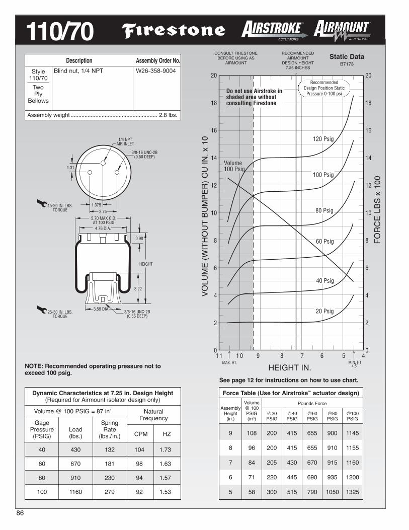
Description Assembly Order No.Blind nut, 1/4 NPT W26-358-9004
Assembly weight ........................................................ 2.8 lbs.
NaturalFrequency
CPM HZ
20
18
16
14
12
10
8
6
4
2
01 1
MAX. HT. MIN. HT4.5”
60 Psig
20 Psig
100 Psig
80 Psig
40 Psig
120 Psig
20
18
16
14
12
10
8
6
4
2
01 0 9 8 7 6 5 4
Do not use Airstroke inshaded area withoutconsulting Firestone
Volume100 Psig
RECOMMENDEDAIRMOUNT
DESIGN HEIGHT7.25 INCHES
Static DataB7173
HEIGHT IN.
HEIGHT
3.22
5.70 MAX O.D.AT 100 PSIG
15-20 IN. LBS.TORQUE
3/8-16 UNC-2B(0.56 DEEP)
4.76 DIA.
1/4 NPTAIR INLET
3.59 DIA.
3/8-16 UNC-2B(0.50 DEEP)
25-30 IN. LBS.TORQUE
2.75
0.98
1.31
1.375
NOTE: Recommended operating pressure not toexceed 100 psig.
See page 12 for instructions on how to use chart.
VOLUME(WITHOUT
BUMPER)CU
IN.x10
FORCELBSx100
Style110/70
TwoPly
Bellows
Force Table (Use for Airstroke™ actuator design)Volume Pounds Force
Assembly @ 100Height PSIG @20 @40 @60 @80 @100(in.) (in3) PSIG PSIG PSIG PSIG PSIG
9 108 200 415 655 900 1145
8 96 200 415 655 910 1155
7 84 205 430 670 915 1160
6 71 220 445 690 935 1200
5 58 300 515 790 1050 1325
86
110/70CONSULT FIRESTONEBEFORE USING AS
AIRMOUNT
Dynamic Characteristics at 7.25 in. Design Height(Required for Airmount isolator design only)
Volume @ 100 PSIG = 87 in3
Gage SpringPressure Load Rate(PSIG) (lbs.) (lbs./ in.)
40 430 132 104 1.73
60 670 181 98 1.63
80 910 230 94 1.57
100 1160 279 92 1.53
RecommendedDesign Position Static
Pressure 0-100 psi

Force Table (Use for Airstroke™ actuator design)Volume Pounds Force
Assembly @ 100Height PSIG @20 @40 @60 @80 @100(in.) (in3) PSIG PSIG PSIG PSIG PSIG
13.0 110 130 280 440 580 74012.0 102 130 280 450 600 76011.0 94 140 280 450 600 76010.0 85 150 290 450 600 7709.0 77 150 290 450 600 7708.0 69 170 310 460 610 7607.0 60 270 420 580 750 920
Dynamic Characteristics at 10.5 in. Design Height(Required for Airmount isolator design only)
Volume @ 100 PSIG = 89 in3
Gage SpringPressure Load Rate(PSIG) (lbs.) (lbs./ in.)
40 290 53 81 1.35
60 450 75 77 1.28
80 600 91 73 1.22
100 770 114 72 1.21
Description Assembly Order No.Blind nuts, 1/4 NPT WO1-358-8119Socket head aluminum beadring (bolts, nuts, washers notincluded, use cap screws) WO1-358-8118
Assembly weight ........................................................ 3.5 lbs.
NaturalFrequency
CPM HZ
15
14
13
12
11
10
9
8
7
6
5
4
3
2
1
0
9 8 7 6.2MAX. HT.
15
14
13
12
11
10
9
8
7
6
5
4
3
2
1
0
15 14 13 12 11 10MIN. HT.
60 Psig
20 Psig
100 Psig
80 Psig
40 Psig
120 Psig
Do not use Airstroke inshaded area withoutconsulting Firestone
Volume100 Psig
CONSULT FIRESTONEBEFORE USING AS
AIRMOUNT
RECOMMENDEDAIRMOUNT
DESIGN HEIGHT10.5 INCHES
Static Data9232
HEIGHT IN.
M8=25 NmTORQUE
127 mm MAX O.D.AT 7 BAR
M12 x 1.75THREADED HOLE
(25 mm DEEP)
M-8 x 1.25BLIND NUTS16 mm DEEP
1/4 BSPAIR INLET
44 mm
114 mm DIA.
121 mm
HEIGHT
111 mm DIA.
M12=35 NmTORQUE
NOTE: Bellows will not compress properly with lessthan 10 PSIG internal pressure.NOTE: A bead plate part is shown. This part is alsoavailable with a bead ring. Bolts are not included.See pages 8-10 for explanation.
See page 12 for instructions on how to use chart.
VOLUMECU
IN.x10
FORCELBSx100
Style1T12E-3
TwoPly
Bellows
87
1T12E-3
RecommendedDesign Position Static
Pressure 0-100 psi

Description Assembly Order No.Blind nuts, 1/4 NPT WO1-358-5310Blind nuts, 1/4 NPT, bumper WO1-358-5311Blind nuts, 3/4 NPT WO1-358-5305Blind nuts, 3/4 NPT, bumper WO1-358-5306Countersunk steel bead ring13/4 bolts, nuts, washers WO1-358-5307
Assembly weight ........................................................ 6.5 lbs.
9 7 5MAX. HT.
4
3
2
1
0MIN. HT.
60 Psig
20 Psig
100 Psig
80 Psig
40 Psig
120 PsigVolume100 Psig
Do not use Airstroke inshaded area withoutconsulting Firestone
4
3
2
1
0
15 13 11BUMPER CONTACT
5.4 IN.
CONSULT FIRESTONEBEFORE USING AS
AIRMOUNT
RECOMMENDEDAIRMOUNT
DESIGN HEIGHT9.0 INCHES
Static Data3019
HEIGHT IN.
9.1 MAX O.D.AT 100 PSIG
HEIGHT
7.25 DIA.
3/8-16 BLIND NUTS(5/8 DEEP) 1/4 OR 3/4 NPT
AIR INLET
3.50
1.75*
OPTIONALBUMPER
*(1.50 FOR 3/4)
3.16
6.31 DIA.
1/2-13 THREADED HOLE(3/4 DEEP)
15-20 FT. LBS.TORQUE
25-30 FT. LBS.TORQUE
NOTE: Bellows will not compress properly with lessthan 10 PSIG internal pressure.NOTE: A bead plate part is shown. This part is alsoavailable with a bead ring. Bolts are not included.See pages 8-10 for explanation.
See page 12 for instructions on how to use chart.
VOLUME(WITHOUT
BUMPER)CU
IN.x100
FORCELBSx1000
Style1T14C-1
TwoPly
Bellows
Dynamic Characteristics at 9.0 in. Design Height(Required for Airmount isolator design only)
Volume @ 100 PSIG = 280 in3
Gage SpringPressure Load Rate(PSIG) (lbs.) (lbs./ in.)
40 1,170 250 85 1.42
60 1,890 398 86 1.44
80 2,570 535 86 1.43
100 3,240 658 85 1.41
NaturalFrequency
CPM HZ
Force Table (Use for Airstroke™ actuator design)Volume Pounds Force
Assembly @ 100Height PSIG @20 @40 @60 @80 @100(in.) (in3) PSIG PSIG PSIG PSIG PSIG
12.0 376 540 1,010 1,530 2,040 2,60011.0 347 570 1,160 1,770 2,380 3,01010.0 314 590 1,210 1,880 2,540 3,2209.0 280 590 1,190 1,890 2,570 3,2408.0 246 580 1,200 1,890 2,570 3,2407.0 211 620 1,240 1,920 2,600 3,3006.0 176 740 1,380 2,060 2,790 3,530
88
RecommendedDesign Position Static
Pressure 0-100 psi
1T14C-1

Dynamic Characteristics at 10.0 in. Design Height(Required for Airmount isolator design only)
Volume @ 100 PSIG = 313 in3
Gage SpringPressure Load Rate(PSIG) (lbs.) (lbs./ in.)
40 1,180 280 92 1.53
60 1,810 356 83 1.39
80 2,450 453 81 1.35
100 3,120 552 79 1.32
Description Assembly Order No.Blind nuts, 1/4 NPT WO1-358-5405
Assembly weight ........................................................ 6.8 lbs.
NaturalFrequency
CPM HZ
MAX. HT.
4
3
2
1
0MIN. HT.
60 Psig
20 Psig
100 Psig
40 Psig
120 Psig4
3
2
1
0
16 14 12 10 8 5.8
Do not use Airstroke inshaded area withoutconsulting Firestone
Volume100 Psig
80 Psig
CONSULT FIRESTONEBEFORE USING AS
AIRMOUNT
RECOMMENDEDAIRMOUNT
DESIGN HEIGHT10.0 INCHES
Static Data3018
HEIGHT IN.
9.1 MAX O.D.AT 100 PSIG
HEIGHT
7.25 DIA.
3/8-16 BLIND NUTS(5/8 DEEP) 1/4 OR 3/4 NPT
AIR INLET
3.50
1.75*
*(1.50 FOR 3/4)
3.16
6.31 DIA.
1/2-13 THREADED HOLE(3/4 DEEP)
15-20 FT. LBS.TORQUE
25-30 FT. LBS.TORQUE
NOTE: Bellows will not compress properly with lessthan 10 PSIG internal pressure.NOTE: A bead plate part is shown. This part is alsoavailable with a bead ring. Bolts are not included.See pages 8-10 for explanation. See page 12 for instructions on how to use chart.
VOLUME(WITHOUT
BUMPER)CU
IN.x100
FORCELBSx1000
Style1T14C-3
TwoPly
Bellows
Force Table (Use for Airstroke™ actuator design)Volume Pounds Force
Assembly @ 100Height PSIG @20 @40 @60 @80 @100(in.) (in3) PSIG PSIG PSIG PSIG PSIG
14.0 430 410 730 1,080 1,490 1,960
12.0 378 560 1,120 1,680 2,280 2,870
10.0 313 580 1,170 1,820 2,440 3,130
8.0 246 610 1,190 1,810 2,430 3,110
6.0 176 800 1,500 2,180 2,960 3,740
89
1T14C-3
RecommendedDesign Position Static
Pressure 0-100 psi

Description Assembly Order No.Blind nuts, 1/4 NPT WO1-358-5712Blind nuts, 3/4 NPT WO1-358-5708
Assembly weight ........................................................ 7.0 lbs.
MAX. HT.
4
3
2
1
0MIN. HT.
8
6
4
2
0
20 18 16 14 8
60 Psig
20 Psig
100 Psig
40 Psig
120 Psig
80 Psig
12 10
Volume100 Psig
Do not use Airstroke inshaded area withoutconsulting Firestone
CONSULT FIRESTONEBEFORE USING AS
AIRMOUNT
RECOMMENDEDAIRMOUNT
DESIGN HEIGHT13.0 INCHES
Static Data3045
HEIGHT IN.
9.1 MAX O.D.AT 100 PSIG
HEIGHT
7.25 DIA.
3/8-16 BLIND NUTS(5/8 DEEP) 1/4 OR 3/4 NPT
AIR INLET
3.50
1.75*
*(1.50 FOR 3/4)
3.16
6.31 DIA.
1/2-13 THREADED HOLE(3/4 DEEP)
15-20 FT. LBS.TORQUE
25-30 FT. LBS.TORQUE
NOTE: Bellows will not compress properly with lessthan 10 PSIG internal pressure.NOTE: A bead plate part is shown. This part is alsoavailable with a bead ring. Bolts are not included.See pages 8-10 for explanation. See page 12 for instructions on how to use chart.
VOLUME(WITHOUT
BUMPER)CU
IN.x100
FORCELBSx1000
Style1T14C-7
Two PlyBellows
Blind nuts, 1/4 NPT WO1-358-5743Style1T28C-7High
StrengthBellows
Dynamic Characteristics at 13.0 in. Design Height(Required for Airmount isolator design only)
Volume @ 100 PSIG = 490 in3
Gage SpringPressure Load Rate(PSIG) (lbs.) (lbs./ in.)
40 1,250 166 68 1.14
60 1,920 243 67 1.12
80 2,610 305 64 1.07
100 3,260 397 66 1.10
NaturalFrequency
CPM HZ
Force Table (Use for Airstroke™ actuator design)Volume Pounds Force
Assembly @ 100Height PSIG @20 @40 @60 @80 @100(in.) (in3) PSIG PSIG PSIG PSIG PSIG
17.0 615 500 890 1,310 1,790 2,260
15.0 558 600 1,210 1,820 2,460 3,070
13.0 490 600 1,250 1,920 2,610 3,260
11.0 421 660 1,280 1,930 2,610 3,270
9.0 349 820 1,540 2,270 3,040 3,850
1T14C-7
90
RecommendedDesign Position Static
Pressure 0-100 psi

Force Table (Use for Airstroke™ actuator design)Volume Pounds Force
Assembly @ 100Height PSIG @20 @40 @60 @80 @100(in.) (in3) PSIG PSIG PSIG PSIG PSIG
10.0 541 920 1,750 2,600 3,470 4,410
9.0 490 1,030 2,010 3,050 4,050 5,130
8.0 433 1,100 2,090 3,210 4,330 5,470
7.0 373 1,110 2,100 3,220 4,370 5,490
6.0 314 1,160 2,190 3,330 4,480 5,650
5.0 251 1,450 2,570 3,780 5,010 6,290
Dynamic Characteristics at 7.0 in. Design Height(Required for Airmount isolator design only)
Volume @ 100 PSIG = 373 in3
Gage SpringPressure Load Rate(PSIG) (lbs.) (lbs./ in.)
40 2,100 658 105 1.75
60 3,220 908 100 1.66
80 4,370 1,168 97 1.62
100 5,490 1,408 95 1.58
Description Assembly Order No.Blind nuts, 1/4 NPT WO1-358-9400Blind nuts, 1/4 NPT, bumper WO1-358-9402Blind nuts, 3/4 NPT WO1-358-9401
Assembly weight ...................................................... 10.4 lbs.
NaturalFrequency
CPM HZ
8
7
6
5
4
3
2
1
0MAX. HT.
8
7
6
5
4
3
2
1
0MIN. HT.
12 11 10 9 48 7 6 5
60 Psig
20 Psig
100 Psig
40 Psig
120 Psig
80 Psig
Volume100 Psig
Do not use Airstroke inshaded area withoutconsulting Firestone
BUMPER CONTACT5.5 IN.
CONSULT FIRESTONEBEFORE USING AS
AIRMOUNT
RECOMMENDEDAIRMOUNT
DESIGN HEIGHT7.0 INCHES
Static Data4209
HEIGHT IN.
HEIGHTOPTIONALBUMPER
11.2 MAX O.D.AT 100 PSIG
9.25 DIA.
3/8-16 BLIND NUTS(5/8 DEEP) 1/4 OR 3/4 NPT
AIR INLET
6.20
2.88
2.00
9.00 DIA.
1/2-13 THREADED HOLE(3/4 DEEP)
15-20 FT. LBS.TORQUE
25-30 FT. LBS.TORQUE
NOTE: Bellows will not compress properly with lessthan 10 PSIG internal pressure.NOTE: A bead plate part is shown. This part is alsoavailable with a bead ring. Bolts are not included.See pages 8-10 for explanation..
See page 12 for instructions on how to use chart.
VOLUME(WITHOUT
BUMPER)CU
IN.x100
FORCELBSx1000
Style1T15T-1
TwoPly
Bellows
91
1T15T-1
RecommendedDesign Position Static
Pressure 0-100 psi

Description Assembly Order No.Blind nuts, 1/4 NPT WO1-358-9048Blind nuts, 1/4 NPT, bumper WO1-358-9049Blind nuts, 3/4 NPT WO1-358-9051
Assembly weight .......................................................13.7 lbs.8
7
6
5
4
3
2
1
0MAX. HT.
8
7
6
5
4
3
2
1
0MIN. HT.
19 17 15 13 611BUMPER CONTACT
6.4 IN.
9 7
60 Psig
20 Psig
100 Psig
40 Psig
120 Psig
80 Psig
Do not use Airstroke inshaded area withoutconsulting Firestone
Volume100 Psig
CONSULT FIRESTONEBEFORE USING AS
AIRMOUNT
RECOMMENDEDAIRMOUNT
DESIGN HEIGHT12.0 INCHES
Static Data7597
HEIGHT IN.
OPTIONALBUMPER
HEIGHT
11.1 MAX O.D.AT 100 PSIG
9.50 DIA.
3/8-16 BLIND NUTS(5/8 DEEP) 1/4 OR 3/4 NPT
AIR INLET
6.20
2.88
4.12
9.00 DIA.
1/2-13 THREADED HOLE(7/8 DEEP)
(TWO IN PISTON)
15-20 FT. LBS.TORQUE
25-30 FT. LBS.TORQUE
NOTE: Bellows will not compress properly with lessthan 20 PSIG internal pressure.NOTE: A bead plate part is shown. This part is alsoavailable with a bead ring. Bolts are not included.See pages 8-10 for explanation. See page 12 for instructions on how to use chart.
VOLUME(WITHOUT
BUMPER)CU
IN.x100
FORCELBSx1000
Style1T15S-6
TwoPly
Bellows
Dynamic Characteristics at 12.0 in. Design Height(Required for Airmount isolator design only)
Volume @ 100 PSIG = 625 in3
Gage SpringPressure Load Rate(PSIG) (lbs.) (lbs./ in.)
40 2,040 363 79 1.32
60 3,140 513 76 1.26
80 4,220 657 74 1.23
100 5,340 813 73 1.22
NaturalFrequency
CPM HZ
Force Table (Use for Airstroke™ actuator design)Volume Pounds Force
Assembly @ 100Height PSIG @20 @40 @60 @80 @100(in.) (in3) PSIG PSIG PSIG PSIG PSIG
16.0 834 830 1,580 2,140 2,860 3,600
14.0 739 1,010 1,980 2,930 3,980 5,000
12.0 625 980 2,040 3,140 4,220 5,340
10.0 509 1,030 2,100 3,160 4,270 5,410
8.0 392 1,280 2,380 3,520 4,690 5,930
1T15S-6
92
RecommendedDesign Position Static
Pressure 0-100 psi

Dynamic Characteristics at 11.0 in. Design Height(Required for Airmount isolator design only)
Volume @ 100 PSIG = 625 in3
Gage SpringPressure Load Rate(PSIG) (lbs.) (lbs./ in.)
40 2,650 583 88 1.47
60 4,080 823 84 1.40
80 5,510 1,055 82 1.37
100 6,930 1,281 81 1.34
Description Assembly Order No.Blind nuts, 1/4 NPT WO1-358-9414
Assembly weight ...................................................... 15.5 lbs.
NaturalFrequency
CPM HZ
18
16
14
12
10
8
6
4
2
0MAX. HT.
9
8
7
6
5
4
3
2
1
0MIN. HT.
18 16 14 12 610BUMPER CONTACT
6.7 IN.
8
Do not use Airstroke inshaded area withoutconsulting Firestone
Volume100 Psig
60 Psig
20 Psig
100 Psig
40 Psig
120 Psig
80 Psig
CONSULT FIRESTONEBEFORE USING AS
AIRMOUNT
RECOMMENDEDAIRMOUNT
DESIGN HEIGHT11.0 INCHES
Static Data3105
HEIGHT IN.
HEIGHTOPTIONALBUMPER
11.7 MAX O.D.AT 100 PSIG
9.25 DIA.
3/8-16 BLIND NUTS(5/8 DEEP) 1/4 OR 3/4 NPT
AIR INLET
6.20
2.88
4.12
9.00 DIA.
1/2-13 THREADED HOLE(7/8 DEEP)
(TWO IN PISTON)
15-20 FT. LBS.TORQUE
25-30 FT. LBS.TORQUE
NOTE: Bellows will not compress properly with lessthan 10 PSIG internal pressure.NOTE: A bead plate part is shown. This part is alsoavailable with a bead ring. Bolts are not included.See pages 8-10 for explanation.
See page 12 for instructions on how to use chart.
VOLUME(WITHOUT
BUMPER)CU
IN.x100
FORCELBSx1000
Style1T15L-4
TwoPly
Bellows
Force Table (Use for Airstroke™ actuator design)Volume Pounds Force
Assembly @ 100Height PSIG @20 @40 @60 @80 @100(in.) (in3) PSIG PSIG PSIG PSIG PSIG
15.0 898 1,120 2,110 3,150 4,300 5,440
13.0 768 1,310 2,630 3,970 5,360 6,720
11.0 625 1,310 2,650 4,080 5,510 6,930
9.0 479 1,310 2,650 4,080 5,500 6,920
7.0 333 1,390 2,780 4,210 5,690 7,120
93
1T15L-4Recommended
Design Position StaticPressure 0-100 psi

MAX. HT.
9
8
7
6
5
4
3
2
1
0MIN. HT.
13 12 11 10 69BUMPER CONTACT
5.3 IN.
8
60 Psig
20 Psig
100 Psig
40 Psig
120 Psig
80 Psig
Volume100 Psig
Do not use Airstroke inshaded area withoutconsulting Firestone9
8
7
6
5
4
3
2
1
0
7 5 4.3
CONSULT FIRESTONEBEFORE USING AS
AIRMOUNT
RECOMMENDEDAIRMOUNT
DESIGN HEIGHT7.5 INCHES
Static Data8826
HEIGHT IN.
HEIGHTOPTIONALBUMPER
12.8 MAX O.D.AT 100 PSIG
9.50 DIA.
3/8-16 BLIND NUTS(5/8 DEEP) 1/4 OR 3/4 NPT
AIR INLET
6.20
2.88
4.12
9.00 DIA.
1/2-13 THREADED HOLE(3/4 DEEP)
(TWO IN PISTON)
15-20 FT. LBS.TORQUE
25-30 FT. LBS.TORQUE
1.96
NOTE: Bellows will not compress properly with lessthan 10 PSIG internal pressure.NOTE: A bead plate part is shown. This part is alsoavailable with a bead ring. Bolts are not included.See pages 8-10 for explanation.
See page 12 for instructions on how to use chart.
VOLUME(WITHOUT
BUMPER)CU
IN.x100
FORCELBSx1000
Dynamic Characteristics at 7.5 in. Design Height(Required for Airmount isolator design only)
Volume @ 100 PSIG = 498 in3
Gage SpringPressure Load Rate(PSIG) (lbs.) (lbs./ in.)
40 2,670 793 102 1.71
60 4,120 1,105 97 1.62
80 5,540 1,399 94 1.57
100 6,990 1,690 92 1.54
NaturalFrequency
CPM HZ
Description Assembly Order No.Blind nuts, 1/4 NPT WO1-358-9030Blind nuts, 1/4 NPT,rubber bumper WO1-358-9031Blind nuts, 3/4 NPT WO1-358-9034Blind nuts, 3/4 NPT,rubber bumper WO1-358-9036Countersunk steel bead ring,13/8 bolts, nuts, washers WO1-358-9038Integral studs, 1/4 NPT WO1-358-9035
Assembly weight ...................................................... 11.5 lbs.
Style1T15M-0
TwoPly
Bellows
Force Table (Use for Airstroke™ actuator design)Volume Pounds Force
Assembly @ 100Height PSIG @20 @40 @60 @80 @100(in.) (in3) PSIG PSIG PSIG PSIG PSIG
11.0 737 980 1,920 2,980 4,120 5,30010.0 675 1,180 2,310 3,550 4,810 6,1309.0 606 1,270 2,540 3,910 5,290 6,7108.0 534 1,300 2,630 4,080 5,500 6,9507.0 462 1,320 2,690 4,140 5,570 7,0106.0 389 1,350 2,730 4,170 5,610 7,0705.0 314 1,410 2,840 4,310 5,840 7,370
1T15M-0
94
RecommendedDesign Position Static
Pressure 0-100 psi

Force Table (Use for Airstroke™ actuator design)Volume Pounds Force
Assembly @ 100Height PSIG @20 @40 @60 @80 @100(in.) (in3) PSIG PSIG PSIG PSIG PSIG
13.0 900 1,000 2,030 3,170 4,320 5,58012.0 835 1,210 2,420 3,720 5,040 6,44011.0 763 1,330 2,680 4,120 5,570 7,10010.0 687 1,380 2,820 4,330 5,850 7,4609.0 609 1,400 2,860 4,390 5,920 7,5308.0 531 1,400 2,850 4,390 5,930 7,5107.0 453 1,410 2,860 4,410 5,950 7,5306.0 374 1,440 2,930 4,530 6,080 7,730
Dynamic Characteristics at 9.5 in. Design Height(Required for Airmount isolator design only)
Volume @ 100 PSIG = 648 in3
Gage SpringPressure Load Rate(PSIG) (lbs.) (lbs./ in.)
40 2,850 693 93 1.54
60 4,370 965 88 1.47
80 5,900 1,238 86 1.43
100 7,510 1,510 84 1.40
NaturalFrequency
CPM HZ
10
9
8
7
6
5
4
3
2
1
0MAX. HT.
10
9
8
7
6
5
4
3
2
1
0MIN. HT.
15 13 11 9BUMPER CONTACT
6.1 IN.
7 5
120 Psig
60 Psig
20 Psig
100 Psig
80 Psig
40 Psig
Volume100 Psig
Do not use Airstroke inshaded area withoutconsulting Firestone
RECOMMENDEDAIRMOUNT
DESIGN HEIGHT9.5 INCHES
Static DataA9109
HEIGHT IN.
OPTIONALBUMPER
12.6 MAX O.D.AT 100 PSIG
9.50 DIA.
3/8-16 BLIND NUTS(5/8 DEEP) 1/4 OR 3/4 NPT
AIR INLET
6.20
2.88
7.88
9.00 DIA.
1/2-13 THREADED HOLE(3/4 DEEP)
(FOUR IN PISTON)
15-20 FT. LBS.TORQUE
25-30 FT. LBS.TORQUE
2.71
HEIGHT
NOTE: Bellows will not compress properly with lessthan 10 PSIG internal pressure.NOTE: A bead plate part is shown. This part is alsoavailable with a bead ring. Bolts are not included.See pages 8-10 for explanation.
See page 12 for instructions on how to use chart.
VOLUME(WITHOUT
BUMPER)CU
IN.x100
FORCELBSx1000
Description Assembly Order No.Blind nuts, 1/4 NPT WO1-358-9042Blind nuts, 1/4 NPT, bumper WO1-358-9053Blind nuts, 3/4 NPT WO1-358-9054Blind nuts, 3/4 NPT, bumper WO1-358-9099
Assembly weight ...................................................... 13.2 lbs.
Style1T15M-2
TwoPly
Bellows
95
1T15M-2Recommended
Design Position StaticPressure 0-100 psi
CONSULT FIRESTONEBEFORE USING AS
AIRMOUNT

Description Assembly Order No.Blind nuts, 1/4 NPT WO1-358-9056Blind nuts, 1/4 NPT, bumper WO1-358-9057Blind nuts, 3/4 NPT WO1-358-9062Blind nuts, 3/4 NPT, bumper WO1-358-9060
Assembly weight ....................................................... 14.3 lbs
20
18
16
14
12
10
8
6
4
2
0MAX. HT.
10
9
8
7
6
5
4
3
2
1
0MIN. HT.
19 17 15 9BUMPER CONTACT
7.1 IN.
613 11
120 Psig
60 Psig
20 Psig
100 Psig
80 Psig
40 Psig
Volume100 Psig
Do not use Airstroke inshaded area withoutconsulting Firestone
7
RECOMMENDEDAIRMOUNT
DESIGN HEIGHT12.0 INCHES
Static Data3068
HEIGHT IN.
HEIGHT
OPTIONALBUMPER
12.6 MAX O.D.AT 100 PSIG
9.50 DIA.
3/8-16 BLIND NUTS(5/8 DEEP) 1/4 OR 3/4 NPT
AIR INLET
6.20
2.88
7.88 DIA.
9.00 DIA.
1/2-13 THREADED HOLE(3/4 DEEP)
(FOUR IN PISTON)
15-20 FT. LBS.TORQUE
25-30 FT. LBS.TORQUE
3.70
NOTE: Bellows will not compress properly with lessthan 10 PSIG internal pressure.NOTE: A bead plate part is shown. This part is alsoavailable with a bead ring. Bolts are not included.See pages 8-10 for explanation. See page 12 for instructions on how to use chart.
VOLUME(WITHOUT
BUMPER)CU
IN.x100
FORCELBSx1000
Style1T15M-4
TwoPly
Bellows
Dynamic Characteristics at 12.0 in. Design Height(Required for Airmount isolator design only)
Volume @ 100 PSIG = 861 in3
Gage SpringPressure Load Rate(PSIG) (lbs.) (lbs./ in.)
40 2,770 459 77 1.28
60 4,210 620 72 1.20
80 5,690 803 71 1.18
100 7,190 986 70 1.16
NaturalFrequency
CPM HZ
Force Table (Use for Airstroke™ actuator design)Volume Pounds Force
Assembly @ 100Height PSIG @20 @40 @60 @80 @100(in.) (in3) PSIG PSIG PSIG PSIG PSIG
16.0 1,146 1,060 2,110 3,240 4,410 5,680
14.0 1,010 1,330 2,650 4,050 5,460 6,910
12.0 861 1,380 2,770 4,210 5,690 7,190
10.0 711 1,390 2,790 4,230 5,720 7,190
8.0 561 1,440 2,880 4,370 5,860 7,400
1T15M-4
96
RecommendedDesign Position Static
Pressure 0-100 psi
CONSULTFIRESTONE
BEFORE USING ASAIRMOUNT

Force Table (Use for Airstroke™ actuator design)Volume Pounds Force
Assembly @ 100Height PSIG @20 @40 @60 @80 @100(in.) (in3) PSIG PSIG PSIG PSIG PSIG
18.0 1,274 1,100 2,220 3,420 4,670 5,980
16.0 1,134 1,290 2,640 4,000 5,410 6,840
14.0 987 1,330 2,730 4,130 5,590 7,030
12.0 841 1,330 2,710 4,170 5,590 7,010
10.0 693 1,380 2,790 4,270 5,730 7,240
8.0 533 1,500 3,060 4,670 6,280 7,950
Dynamic Characteristics at 14.0 in. Design Height(Required for Airmount isolator design only)
Volume @ 100 PSIG = 987 in3
Gage SpringPressure Load Rate(PSIG) (lbs.) (lbs./ in.)
40 2,730 395 71 1.19
60 4,130 541 68 1.13
80 5,590 707 67 1.12
100 7,030 852 65 1.09
NaturalFrequency
CPM HZ
20
18
16
14
12
10
8
6
4
2
0MAX. HT.
10
9
8
7
6
5
4
3
2
1
0MIN. HT.
22 20 18BUMPER CONTACT
7.9 IN.
716 14 812 10
120 Psig
60 Psig
20 Psig
100 Psig
80 Psig
40 Psig
Volume100 Psig
Do not use Airstroke inshaded area withoutconsulting Firestone
RECOMMENDEDAIRMOUNT
DESIGN HEIGHT14.0 INCHES
Static Data4452
HEIGHT IN.
OPTIONALBUMPER
12.6 MAX O.D.AT 100 PSIG
10.25 DIA.
3/8-16 BLIND NUTS(5/8 DEEP) 1/4 OR 3/4 NPT
AIR INLET
6.20
2.88
7.88 DIA.
9.00 DIA.
1/2-13 THREADED HOLE(3/4 DEEP)
(FOUR IN PISTON)
15-20 FT. LBS.TORQUE
25-30 FT. LBS.TORQUE
4.56
HEIGHT
NOTE: Bellows will not compress properly with lessthan 10 PSIG internal pressure.NOTE: A bead plate part is shown. This part is alsoavailable with a bead ring. Bolts are not included.See pages 8-10 for explanation. See page 12 for instructions on how to use chart.
VOLUME(WITHOUT
BUMPER)CU
IN.x100
FORCELBSx1000
Description Assembly Order No.Blind nuts, 1/4 NPT WO1-358-9079Blind nuts, 1/4 NPT, bumper WO1-358-9096Blind nuts, 3/4 NPT WO1-358-9089Blind nuts, 3/4 NPT, bumper WO1-358-9088Blind nuts, 3/4 NPT (pistonnot included) WO1-358-0730
Assembly weight (bead plate version, no bumper)..... 15.7 lbs.
Style1T15M-6
TwoPly
Bellows
97
1T15M-6Recommended
Design Position StaticPressure 0-100 psi
CONSULTFIRESTONE
BEFORE USING ASAIRMOUNT

Description Assembly Order No.Blind nuts, 1/4 NPT WO1-358-9108Blind nuts, 1/4 NPT, bumper WO1-358-9104Blind nuts, 3/4 NPT WO1-358-9106Blind nuts, 3/4 NPT, bumper WO1-358-9117
Assembly weight ...................................................... 18.0 lbs.
20
18
16
14
12
10
8
6
4
2
0MAX. HT.
10
9
8
7
6
5
4
3
2
1
0MIN. HT.
27 25 23 8.521 19 17 15BUMPER CONTACT
9.7 IN.
Volume100 Psig
Do not use Airstroke inshaded area withoutconsulting Firestone
13 11
120 Psig
60 Psig
20 Psig
100 Psig
80 Psig
40 Psig
RECOMMENDEDAIRMOUNT
DESIGN HEIGHT17.0 INCHES
Static Data3797
HEIGHT IN.
HEIGHTOPTIONALBUMPER
12.7 MAX O.D.AT 100 PSIG
10.25 DIA.
3/8-16 BLIND NUTS(5/8 DEEP)
1/4 OR 3/4 NPTAIR INLET
6.20
2.88
7.88 DIA.
9.00 DIA.
1/2-13 THREADED HOLE(3/4 DEEP)
(FOUR IN PISTON)
15-20 FT. LBS.TORQUE
25-30 FT. LBS.TORQUE
NOTE: Bellows will not compress properly with lessthan 10 PSIG internal pressure.NOTE: A bead plate part is shown. This part is alsoavailable with a bead ring. Bolts are not included.See pages 8-10 for explanation. See page 12 for instructions on how to use chart.
VOLUME(WITHOUT
BUMPER)CU
IN.x100
FORCELBSx1000
Style1T15M-9
TwoPly
Bellows
Dynamic Characteristics at 17.0 in. Design Height(Required for Airmount isolator design only)
Volume @ 100 PSIG = 1,217 in3
Gage SpringPressure Load Rate(PSIG) (lbs.) (lbs./ in.)
40 2,770 287 60 1.01
60 4,250 425 59 .99
80 5,680 546 58 .97
100 7,140 659 57 .95
NaturalFrequency
CPM HZ
Force Table (Use for Airstroke™ actuator design)Volume Pounds Force
Assembly @ 100Height PSIG @20 @40 @60 @80 @100(in.) (in3) PSIG PSIG PSIG PSIG PSIG
23.0 1,658 1,090 2,150 3,340 4,560 5,85021.0 1,517 1,290 2,600 4,020 5,380 6,86019.0 1,368 1,340 2,780 4,240 5,660 7,11017.0 1,217 1,370 2,770 4,250 5,680 7,14015.0 1,067 1,380 2,810 4,290 5,690 7,15013.0 916 1,390 2,810 4,280 5,700 7,17011.0 760 1,460 2,950 4,430 5,940 7,5009.0 596 1,580 3,200 4,880 6,550 8,230
1T15M-9
98
RecommendedDesign Position Static
Pressure 0-100 psi
CONSULTFIRESTONE
BEFORE USING ASAIRMOUNT

Force Table (Use for Airstroke™ actuator design)Volume Pounds Force
Assembly @ 100Height PSIG @20 @40 @60 @80 @100(in.) (in3) PSIG PSIG PSIG PSIG PSIG
18.50 1,480 1,398 2,605 3,859 5,194 6,645
16.50 1,328 1,705 3,309 4,952 6,624 8,350
14.50 1,155 1,760 3,482 5,293 7,095 8,964
12.50 969 1,760 3,482 5,297 7,101 8,984
10.50 778 1,760 3,482 5,297 7,101 8,984
8.50 591 2,126 3,876 5,748 7,597 9,515
Dynamic Characteristics at 13.0 in. Design Height(Required for Airmount isolator design only)
Volume @ 100 PSIG = 921 in3
Gage SpringPressure Load Rate(PSIG) (lbs.) (lbs./ in.)
40 3,482 532 73 1.22
60 5,297 777 72 1.20
80 7,101 982 70 1.17
100 8,984 1,227 69 1.15
Description Assembly Order No.Blind nuts, 1/4 NPT WO1-358-9148Blind nuts, 1/4 NPT, bumper WO1-358-9149Blind nuts, 3/4 NPT WO1-358-9172Blind nuts, 3/4 NPT, bumper WO1-358-9160Countersunk steel bead ring13/4 bolts, nuts, washers WO1-358-9165
Assembly weight .................................................... 24.60 lbs.
NaturalFrequency
CPM HZ
32
28
24
20
16
12
8
4
0
22 20 18 16 14 12 10 8 6.5 Bumper Contact
(7.4)
40 Psig
20 Psig
MAX. HT. MIN. HT.
16
14
12
10
8
6
4
2
0
Do not use Airstroke inshaded area withoutconsulting Firestone
120 Psig
60 Psig
80 Psig
100 Psig
Volume100 Psig
CONSULTFIRESTONE
BEFORE USING ASAIRMOUNT
RECOMMENDEDAIRMOUNT
DESIGN HEIGHT13.0 INCHES
Static DataB0308
HEIGHT IN.
3.125
14.2 MAX O.D.AT 100 PSIG
HEIGHT
6.25
6.25
10.25 DIA.
1/4 NPTAIR INLET
OPTIONALBUMPER
3/8-16 BLIND NUTS(5/8 DEEP)
7.88 DIA.
11.31 DIA.
1/2-13 THREADED HOLES(1.00 DEEP)
(FOUR IN PISTON)
25-30 FT. LBS.TORQUE
15-20 FT. LBS.TORQUE
NOTE: Bellows will not compress properly with lessthan 20 PSIG internal pressure.NOTE: A bead plate part is shown. This part is alsoavailable with a bead ring. Bolts are not included.See pages 8-10 for explanation. See page 12 for instructions on how to use chart.
VOLUME(WITHOUT
BUMPER)CU
IN.x100
FORCELBSx1000
Style1T19L-7
TwoPly
Bellows
99
1T19L-7Recommended
Design Position StaticPressure 0-100 psi

Force Table (Use for Airstroke™ actuator design)Volume Pounds Force
Assembly @ 100Height PSIG @20 @40 @60 @80 @100(in.) (in3) PSIG PSIG PSIG PSIG PSIG
20.0 1,597 1,650 3,341 5,068 6,843 8,619
18.0 1,427 1,650 3,411 5,151 6,911 8,711
16.0 1,247 1,650 3,411 5,151 6,911 8,711
14.0 1,060 1,650 3,411 5,151 6,911 8,711
12.0 872 1,830 3,510 5,278 7,101 8,903
10.0 688 2,283 4,100 5,960 7,946 9,911
Description Assembly Order No.Blind nuts, 1/4 NPT WO1-358-9155Blind nuts, 1/4 NPT, bumper WO1-358-9156Blind nuts, 3/4 NPT WO1-358-9153Blind nuts, 3/4 NPT, bumper WO1-358-2132Countersunk steel bead ring13/4 bolts, nuts, washers WO1-358-9162
Assembly weight ...................................................... 22.6 lbs.
32
28
24
20
16
12
8
4
0
28 26 24 22 20 18 16 14 12 10 8 Bumper Contact
(8.5)
MAX. HT. MIN. HT.
16
14
12
10
8
6
4
2
0
Do not use Airstroke inshaded area withoutconsulting Firestone
Volume100 Psig
40 Psig
20 Psig
60 Psig
100 Psig
80 Psig
120 Psig
CONSULT FIRESTONEBEFORE USING AS
AIRMOUNT
RECOMMENDEDAIRMOUNT
DESIGN HEIGHT17.0 INCHES
Static DataB0307
HEIGHT IN.
3.125
14.2 MAX O.D.AT 100 PSIG
HEIGHT
6.25
6.25
10.25 DIA.
1/4 NPTAIR INLET
OPTIONALBUMPER
3/8-16 BLIND NUTS(5/8 DEEP)
7.88 DIA.
11.31 DIA.
1/2-13 THREADED HOLES(1.00 DEEP)
(FOUR IN PISTON)
25-30 FT. LBS.TORQUE
15-20 FT. LBS.TORQUE
NOTE: Bellows will not compress properly with lessthan 20 PSIG internal pressure.NOTE: A bead plate part is shown. This part is alsoavailable with a bead ring. Bolts are not included.See pages 8-10 for explanation. See page 12 for instructions on how to use chart.
VOLUME(WITHOUT
BUMPER)CU
IN.x100
FORCELBSx1000
Style1T19L-11
TwoPly
Bellows
Dynamic Characteristics at 17.0 in. Design Height(Required for Airmount isolator design only)
Volume @ 100 PSIG = 1,337 in3
Gage SpringPressure Load Rate(PSIG) (lbs.) (lbs./ in.)
40 3,411 428 67 1.12
60 5,151 602 64 1.07
80 6,911 765 63 1.05
100 8,711 927 61 1.02
NaturalFrequency
CPM HZ
1T19L-11
100
RecommendedDesign Position Static
Pressure 0-100 psi

the new...
Polyactuatorfrom Firestone
Description
• The minimum height on this model is only 0.63 inches (16 mm) so it will fit in verysmall spaces.
• It is capable of strokes up to .5 inch (13mm) and forces over 100 lbs (.45 kN) at50 psig (3.5 bar).
0
25
50
75
100
125
150
175
200
225
0.0 0.1 0.2 0.3 0.4 0.5
Airomatic ActuatorLoad vs. Stroke
Load
(lbf)
Stroke (in)
10 Psig
20 Psig
30 Psig
40 Psig
50 Psig
X-8531AW-
XXX
70-P-13 (WA1-358-5674)Firestone Industrial Products Company is announcing the introduction of a completely new range ofpneumatic actuators. The Airomatic™ polyactuator line consists of engineered plastic moldedelements welded together in a sealed unit.
101
Maximum recommended pressure is 50 psi. Do not use unrestricted.
For more information, please visit:
http://www.fsip.com/airomatic
3.00
no load0.63 in.
max.1.13 in.
U.S. Patent 6,612,223

WO1-358-7008 STYLE 19 46WO1-358-7009 STYLE 19 46WO1-358-7011 STYLE 19 46WO1-358-7012 STYLE 19 46WO1-358-7019 STYLE 333 75WO1-358-7023 STYLE 19 46WO1-358-7025 STYLE 25 56WO1-358-7030 STYLE 25 56WO1-358-7035 STYLE 25 56WO1-358-7039 STYLE 19-.75 47WO1-358-7040 STYLE 19-.75 47WO1-358-7042 STYLE 19-.75 47WO1-358-7043 STYLE 19-.75 47WO1-358-7047 STYLE 25 56WO1-358-7080 STYLE 202 60WO1-358-7091 STYLE 113-1 49WO1-358-7092 STYLE 113-1 49WO1-358-7094 STYLE 113-1 49WO1-358-7101 STYLE 113 48WO1-358-7103 STYLE 113 48WO1-358-7104 STYLE 113 48WO1-358-7109 STYLE 113 48WO1-358-7110 STYLE 113 48WO1-358-7119 STYLE 202 60WO1-358-7139 STYLE 21 64WO1-358-7143 STYLE 21 64WO1-358-7144 STYLE 21 64WO1-358-7145 STYLE 21 64WO1-358-7146 STYLE 21 64WO1-358-7180 STYLE 22 62WO1-358-7184 STYLE 22 62WO1-358-7185 STYLE 22 62WO1-358-7191 STYLE 28 67WO1-358-7192 STYLE 28 67WO1-358-7194 STYLE 28 67WO1-358-7197 STYLE 121 52WO1-358-7201 STYLE 29 69WO1-358-7203 STYLE 29 69WO1-358-7205 STYLE 29 69WO1-358-7208 STYLE 205 64WO1-358-7219 STYLE 215 71WO1-358-7220 STYLE 215 71WO1-358-7221 STYLE 205 64WO1-358-7224 STYLE 205 64WO1-358-7225 STYLE 203 68WO1-358-7227 STYLE 203 68WO1-358-7228 STYLE 218 68WO1-358-7230 STYLE 215 71WO1-358-7233 STYLE 215 71WO1-358-7237 STYLE 205 64WO1-358-7239 STYLE 207 69WO1-358-7242 STYLE 207 69WO1-358-7244 STYLE 201 67WO1-358-7250 STYLE 210 62WO1-358-7251 STYLE 210 62WO1-358-7258 STYLE 210 62WO1-358-7271 STYLE 28 67WO1-358-7272 STYLE 121 52WO1-358-7273 STYLE 203 68WO1-358-7274 STYLE 323 77WO1-358-7275 STYLE 29 69WO1-358-7276 STYLE 320 78WO1-358-7277 STYLE 113-1 49WO1-358-7286 STYLE 312 76WO1-358-7291 STYLE 210 62WO1-358-7301 STYLE 215 71WO1-358-7302 STYLE 215 71WO1-358-7304 STYLE 321 79WO1-358-7306 STYLE 321 79WO1-358-7319 STYLE 319 79WO1-358-7320 STYLE 321 79WO1-358-7324 STYLE 320 78
ORDER NUMBER STYLE NUMBER SEE PAGE
WO1-A72-7518 STYLE 116 43WO1-139-0201 STYLE 201 67WO1-358-0010 STYLE 16 38WO1-358-0017 STYLE 16 38WO1-358-0025 STYLE 25 56WO1-358-0030 STYLE 25 56WO1-358-0048 STYLE 255-1.5 57WO1-358-0100 STYLE 110 42WO1-358-0112 STYLE 110 42WO1-358-0118 STYLE 115 45WO1-358-0119 STYLE 119 51WO1-358-0127 STYLE 131 40WO1-358-0131 STYLE 131 40WO1-358-0133 STYLE 116 43WO1-358-0134 STYLE 19 46WO1-358-0135 STYLE 113 48WO1-358-0142 STYLE 26 59WO1-358-0147 STYLE 138-1.5 54WO1-358-0150 STYLE 113-1 49WO1-358-0152 STYLE 20-2 61WO1-358-0205 STYLE 203 68WO1-358-0207 STYLE 207 69WO1-358-0213 STYLE 21 64WO1-358-0226 STYLE 22 62WO1-358-0231 STYLE 128 48WO1-358-0259 STYLE 22-1.5 63WO1-358-0286 STYLE 16 38WO1-358-0324 STYLE 324 77WO1-358-0480 STYLE 1X84D-1 81WO1-358-0730 STYLE 1T15M-6 97WO1-358-0987 STYLE 320 78WO1-358-1023 STYLE 348-3 80WO1-358-1098 STYLE 39 74WO1-358-1099 STYLE 39 74WO1-358-1152 STYLE 160 41WO1-358-2132 STYLE 1T19L-11 100WO1-358-3400 STYLE 224 58WO1-358-3403 STYLE 224 58WO1-358-5126 STYLE 200 70WO1-358-5135 STYLE 121 52WO1-358-5305 STYLE 1T14C-1 88WO1-358-5306 STYLE 1T14C-1 88WO1-358-5307 STYLE 1T14C-1 88WO1-358-5310 STYLE 1T14C-1 88WO1-358-5311 STYLE 1T14C-1 88WO1-358-5405 STYLE 1T14C-3 89WO1-358-5708 STYLE 1T14C-7 90WO1-358-5712 STYLE 1T14C-7 90WO1-358-5743 STYLE 1T28C-7 90WO1-358-6800 STYLE 21-2 65WO1-358-6801 STYLE 21-2 65WO1-358-6810 STYLE 233-2 66WO1-358-6811 STYLE 233-2 66WO1-358-6900 STYLE 20 60WO1-358-6901 STYLE 20 60WO1-358-6910 STYLE 20 60WO1-358-6911 STYLE 20 60WO1-358-6923 STYLE 20 60WO1-358-6947 STYLE 20-2 61WO1-358-6951 STYLE 20-2 61WO1-358-6952 STYLE 20-2 61WO1-358-6955 STYLE 255-1.5 57WO1-358-6956 STYLE 255-1.5 57WO1-358-6996 STYLE 16 38WO1-358-7001 STYLE 16 38
ORDER NUMBER STYLE NUMBER SEE PAGE
INDEXORDER NUMBER TO STYLENUMBER TO PAGE NUMBER
102

WO1-358-8118 STYLE 1T12E-3 87WO1-358-8119 STYLE 1T12E-3 87WO1-358-8149 STYLE 128 48WO1-358-8150 STYLE 128 48WO1-358-8151 STYLE 128 48WO1-358-8152 STYLE 128 48W01-358-8158 STYLE 153-2 50WO1-358-8160 STYLE 128-1 49WO1-358-9030 STYLE 1T15M-0 94WO1-358-9031 STYLE 1T15M-0 94WO1-358-9034 STYLE 1T15M-0 94WO1-358-9035 STYLE 1T15M-0 94WO1-358-9036 STYLE 1T15M-0 94WO1-358-9038 STYLE 1T15M-0 94WO1-358-9042 STYLE 1T15M-2 95WO1-358-9048 STYLE 1T15S-6 92WO1-358-9049 STYLE 1T15S-6 92WO1-358-9051 STYLE 1T15S-6 92WO1-358-9053 STYLE 1T15M-2 95WO1-358-9054 STYLE 1T15M-2 95WO1-358-9056 STYLE 1T15M-4 96WO1-358-9057 STYLE 1T15M-4 96WO1-358-9060 STYLE 1T15M-4 96WO1-358-9062 STYLE 1T15M-4 96WO1-358-9079 STYLE 1T15M-6 97WO1-358-9088 STYLE 1T15M-6 97WO1-358-9089 STYLE 1T15M-6 97WO1-358-9096 STYLE 1T15M-6 97WO1-358-9099 STYLE 1T15M-2 95WO1-358-9104 STYLE 1T15M-9 98WO1-358-9106 STYLE 1T15M-9 98WO1-358-9108 STYLE 1T15M-9 98WO1-358-9117 STYLE 1T15M-9 98WO1-358-9148 STYLE 1T19L-7 99WO1-358-9149 STYLE 1T19L-7 99WO1-358-9153 STYLE 1T19L-11 100WO1-358-9155 STYLE 1T19L-11 100WO1-358-9156 STYLE 1T19L-11 100WO1-358-9160 STYLE 1T19L-7 99WO1-358-9162 STYLE 1T19L-11 100WO1-358-9165 STYLE 1T19L-7 99WO1-358-9172 STYLE 1T19L-7 99WO1-358-9188 STYLE 1X84D-1 81WO1-358-9190 STYLE 1X84D-1 81WO1-358-9400 STYLE 1T15T-1 91WO1-358-9401 STYLE 1T15T-1 91WO1-358-9402 STYLE 1T15T-1 91WO1-358-9414 STYLE 1T15L-4 93WO1-358-9528 STYLE 328 78WO1-358-9529 STYLE 21-2 65WO1-358-9601 STYLE 148-1 55WO1-358-9602 STYLE 248-2 72WO1-358-9603 STYLE 348-3 80WO1-410-7517 STYLE 116-1 44WO1-606-7025 STYLE 25 56WO1-606-7115 STYLE 115 45WO1-753-7113 STYLE 113 48WO1-753-7114 STYLE 113 48WO2-358-3000 STYLE 1M1A-0 34WO2-358-3001 STYLE 1M1A-0 34WO2-358-3002 STYLE 2M1A 36WO2-358-3003 STYLE 1M1A-1 35WO2-358-3004 STYLE 2M1A 36WO2-358-3005 STYLE 1M1A-0 34WO2-358-3008 STYLE 2M2A 37WO2-358-4001 STYLE 4001 82WO2-358-5000 STYLE 16ST 39WO2-358-5002 STYLE 16ST 39WO2-358-7002 STYLE 7002 83WO2-358-7010 STYLE 7010 84WO2-358-7012 STYLE 7012 85WO2-358-9004 STYLE 110/70 86
ORDER NUMBER STYLE NUMBER SEE PAGEORDER NUMBER STYLE NUMBER SEE PAGEWO1-358-7325 STYLE 26 59WO1-358-7327 STYLE 26 59WO1-358-7333 STYLE 26 59WO1-358-7400 STYLE 22 62WO1-358-7431 STYLE 22 62WO1-358-7442 STYLE 22-1.5 63WO1-358-7443 STYLE 22-1.5 63WO1-358-7444 STYLE 22-1.5 63WO1-358-7451 STYLE 110 42WO1-358-7458 STYLE 115 45WO1-358-7459 STYLE 115 45WO1-358-7460 STYLE 115 45WO1-358-7465 STYLE 115 45WO1-358-7469 STYLE 115 45WO1-358-7473 STYLE 22-1.5 63WO1-358-7477 STYLE 119 51WO1-358-7478 STYLE 119 51WO1-358-7484 STYLE 110 42WO1-358-7561 STYLE 116 43WO1-358-7564 STYLE 116 43WO1-358-7568 STYLE 116 43WO1-358-7592 STYLE 160 41WO1-358-7598 STYLE 116-1 44WO1-358-7600 STYLE 117 43WO1-358-7602 STYLE 117 42WO1-358-7605 STYLE 116-1 44WO1-358-7606 STYLE 117 43WO1-358-7649 STYLE 124 45WO1-358-7650 STYLE 124 45WO1-358-7726 STYLE 126 53WO1-358-7727 STYLE 126 53WO1-358-7729 STYLE 131 40WO1-358-7731 STYLE 131 40WO1-358-7734 STYLE 138-1.5 54WO1-358-7737 STYLE 138-1.5 54WO1-358-7742 STYLE 131 40WO1-358-7751 STYLE 160 41WO1-358-7760 STYLE 312 76WO1-358-7761 STYLE 312 76WO1-358-7772 STYLE 200 70WO1-358-7775 STYLE 200 70WO1-358-7781 STYLE 233-2 66WO1-358-7801 STYLE 313 74WO1-358-7802 STYLE 313 74WO1-358-7807 STYLE 313 74WO1-358-7808 STYLE 313 74WO1-358-7811 STYLE 313 74WO1-358-7815 STYLE 39 74WO1-358-7823 STYLE 323 77WO1-358-7829 STYLE 324 77WO1-358-7830 STYLE 333 75WO1-358-7838 STYLE 333 75WO1-358-7842 STYLE 333 75WO1-358-7845 STYLE 333 75WO1-358-7900 STYLE 313 74WO1-358-7901 STYLE 20 60WO1-358-7902 STYLE 29 69WO1-358-7910 STYLE 215 71WO1-358-7912 STYLE 215 71WO1-358-7914 STYLE 312 75WO1-358-7918 STYLE 321 79WO1-358-7919 STYLE 321 79WO1-358-7921 STYLE 323 77WO1-358-7925 STYLE 28 67WO1-358-7926 STYLE 314 76WO1-358-7928 STYLE 210 62WO1-358-7929 STYLE 205 64WO1-358-8003 STYLE 314 76WO1-358-8004 STYLE 314 76WO1-358-8009 STYLE 314 76WO1-358-8047 STYLE 352 73WO1-358-8048 STYLE 352 73
103

104

105
AIRSTROKE™ ACTUATORDESIGN PARAMETER WORKSHEET
PLEASECUTALONG
DOTTED
LINE
1. FORCE REQUIRED:
2. STROKE REQUIRED:
3. AVAILABLE AIR PRESSURE:
4. ANGLE OF MOTION (PLEASE SKETCH):
5. LATERAL SPACE AVAILABLE FORAIRSTROKE ACTUATOR(S):
6. ENVIRONMENTAL CONDITIONS:
7. CYCLE RATE:
8. RESPONSE TIME REQUIRED:
SPECIAL REQUIREMENTS:
REMARKS NAMECOMPANYADDRESSCITY/COUNTRY/CODETELEPHONE
DATE
PLEASE SKETCH WITH DIMENSIONS
Please return to your local stocking distributor, or send directly to:Firestone Industrial Products Company, 310 E. 96th Street, Indianapolis, IN 46240 U.S.A.
Phone: 1-800-888-0650

106

107
PLEASECUTALONG
DOTTED
LINE
AIRMOUNT™ ISOLATORDESIGN PARAMETER WORKSHEET
FOR VIBRATION ISOLATIONA)TO PREVENT OUTGOING VIBRATION TRANS-MISSION (INTO THE SURROUNDING AREA), OR
B)FOR ISOLATING DELICATE EQUIPMENT FROMINCOMING VIBRATIONS, PLEASE COMPLETETHE FOLLOWING:1. DESCRIPTION OF EQUIPMENT:
2. TYPE OF DISTURBANCE TO BE ISOLATED(FORCED FREQUENCY OF VIBRATION):
3. MAXIMUM WEIGHT (lbs.)4. WEIGHT DISTRIBUTION (PLEASE SKETCH ONGRAPH).5. DESIRED NUMBER OF MOUNTING POINTS:6. POSITION OF MOUNTING POINTS (PLEASESKETCH ON GRAPH).7. SPACE (DIAMETER) AVAILABLE FOR AIRMOUNTISOLATORS (inches):
8. AIR PRESSURE AVAILABLE:9. DIMENSIONS: HEIGHT (inches)LENGTH (inches)WIDTH (inches)
10. POSITION OF CENTER OF GRAVITY (C.G., ,mm UP FROM BASE)
11. DISTURBING FREQUENCY(ff)a) FOR A) ABOVE, MACHINE SPEED, (rpm)b) FOR B) ABOVE, FREQUENCY OF INCOMINGVIBRATION (Hz)
12. PERCENT ISOLATION DESIRED (%):
NAMECOMPANYADDRESSCITY/ COUNTRY/CODEPHONE
FOR ISOLATING AN UNBALANCED MASS13. PLEASE COMPLETE 1 THROUGH 12, ANDALSO INCLUDE:
14. TYPE OF MOVING COMPONENTS (UNBAL-ANCED MASS):
15. WEIGHT OF UNBALANCED MOVING MASS (lbs.):
16. RADIUS OF MOVEMENT (inches):17. DIRECTION OF MOVEMENT (PLEASE SKETCHON GRAPH).
FOR SHOCK IMPACT ISOLATION18. PLEASE COMPLETE 1, AND ALSO INCLUDE:19. WEIGHT OF MOVING OBJECT (lbs.):20. SPEED OF MOVING OBJECT (in/sec):21. DISTANCE OF FREE FALL (inches):22. DESIRED STOPPING DISTANCE (inches):23. SPACE (DIAMETER) AVAILABLE FOR SHOCKIMPACT ISOLATOR(S) (inches):
DATE
�
Please return to your local stocking distributor, or send directly to:Firestone Industrial Products Company, 310 E. 96th Street, Indianapolis, IN 46240 U.S.A.
Phone: 1-800-888-0650

108

109
INDEXSTYLE NUMBER TO PAGE NUMBER
16 38
16-ST 39
131 40
160 41
110 42
116 117 43
116-1 44
115 124 45
19 46
19-.75 47
113 128 48
113-1 128-1 49
153-2 50
119 51
121 52
126 53
138-1.5 54
148-1 55
1X84D-1 81
4001 82
7002 83
7010 84
7012 85
110/70 86
1T12E-3 87
1T14C-1 88
1T14C-3 89
1T14C-7 1T28F-8 90
1T15T-1 91
1T15S-6 92
1T15L-4 93
1T15M-0 94
1T15M-2 95
1T15M-4 96
1T15M-6 97
1T15M-9 98
1T19L-7 99
1T19L-11 100
25 57
255-1.5 57
224 58
26 59
20 202 60
20-2 61
22 210 62
22-1.5 63
21 205 64
21-2 65
233-2 66
28 201 67
203 218 68
29 207 69
200 70
215 71
248-2 72
HIGH STRENGTHSTYLE NO.
SEE PAGETWO PLYSTYLE NO.
SINGLE CONVOLUTION
HIGH STRENGTHSTYLE NO.
SEE PAGETWO PLYSTYLE NO.
TRIPLE CONVOLUTION
REVERSIBLE SLEEVE
DOUBLE CONVOLUTION
SHAPED SLEEVE
352 73
313 39 74
333 75
312 314 76
323 324 77
320 328 78
321 79
348-3 80
1M1A 34
1M1A-1 35
2M1A 36
2M2A 37