AIR SPRING APPLICATION CONSIDERATIONS FOR ... Commercial Vehicle Applications.pdfAIR SPRING...
13
AIR SPRING APPLICATION CONSIDERATIONS FOR COMMERCIAL VEHICLES This section is devoted to bridging the gap between the theoretical characteristic of air springs and their functional application. Recognizing that the usual application of these springs will be in conjunction with other components making up a vehicle suspension, examples are presented here in terms of the air spring design for actual suspension systems. From this presentation, the designer should be able to determine the sequence of data accumulation, analysis, and calculation required to arrive at a suitable design within his particular parameters. He should also gain an understanding of how the air spring characteristics, discussed in earlier chapters, become pertinent to overall suspension design. In addition to the design procedure examples and calculations, a section of this chapter presents generalized considerations for air spring suspension design which have evolved from the experience of suspension designers and air spring manufacturers. The advantages of pneumatic suspension are not automatically attained. The entire suspension must be properly designed if it is to take full advantage of air spring capabilities and to compensate for their few limitations. 1. REASONS FOR USING AIR SPRINGS A. To provide a more comfortable ride for vehicle occupants. B. To obtain better cargo protection through low spring rate and natural frequency C. To obtain longer vehicle life through less damage from road shock and vibration. D. To make a lighter vehicle possible, thus allowing an equivalent increase in cargo mass. E. To optimize load distribution on multi-axle units. F. To provide for auxiliary axle pick-up when the axle is not required, thus providing operating economies and improved maneuverability. G. To allow automatic levelling. With automatic height sensors, there is no change in vehicle height from an unloaded to a fully loaded condition. This permits the cargo space to be designed with a higher top and a lower floor without interfering with the tires while still staying within maximum vehicle height limits. Also, a constant height is maintained for use at loading docks and for trailer pick-ups. H. To protect the infrastructure. Low spring rate and natural frequency plus excellent load distribution protects the roads and may make pneumatically sprung vehicles acceptable on roads where units of large mass are not now allowed. 2. SUSPENSION DESIGN CONSIDERATIONS To design a pneumatic suspension system the designer must know, in addition to what is needed for the basic design, what will be required of the air spring and what is needed to fit the spring into the total system. The system requirements that the spring is to supply are as follows: 1. Satisfactory mechanical operation over the full axle travel. 2. Support for the sprung mass with the available air pressure. 3. The desired dynamic spring rate and system natural frequency throughout the sprung mass load range. 4. Desirable or at least satisfactory dynamic force characteristics throughout the full axle travel. The air spring requirements that the suspension system must provide are as follows: 1. A space envelope that allows the spring to function properly at all heights. 2. An operating environment that does not seriously affect spring life. To take maximum advantage of these possibilities, many considerations should be kept in mind. There is reserve capability and versatility built into air springs. While some violations of the following application principles can be tolerated, it is best to design to obtain as many preferred conditions as possible for long, trouble-free air spring service. Air springs can be utilized in many geometries, but in designing to get the maximum benefit in one area, care should be taken not to create an unacceptable situation in another area. The following are significant design considerations: 1. Design Height - The design height should be established within the recommended design height range since life and performance characteristics may both be adversely affected if the springs operate continuously either above or below their design range. 2. Operating Pressures - For lowest spring rate and natural frequency for a particular suspension design, springs should be operated at normal pressures within 80-100 PSIG. Moderate operating pressures (40-80 PSIG) will provide maximum life. It is also necessary to maintain some positive pressure under lightest load and full rebound conditions. 3. Vehicle Roll Rates - Low spring rates mean less control in vehicle roll; therefore, some auxiliary restoring force must be supplied. Levelling valves, shock absorbers, and shaped pistons may sometimes help in this situation but it is best to have a suspension design or linkage which supplies this restoring force. Some methods that have proven successful are: 1.) Using a roll stabilizing bar connecting one suspension arm with the other. 2.) Having rigid suspension arms with a rigid axis connected to the suspension arms with flexible mountings. 3.) Using flexible suspension arms attached rigidly to the axle.
Transcript of AIR SPRING APPLICATION CONSIDERATIONS FOR ... Commercial Vehicle Applications.pdfAIR SPRING...

AIR SPRING APPLICATIONCONSIDERATIONS FOR COMMERCIAL
VEHICLESThis section is devoted to bridging the gap between the theoretical characteristic of air springs and their functional application. Recognizing that the usual application of these springs will be in conjunction with other components making up a vehicle suspension, examples are presented here in terms of the air spring design for actual suspension systems. From this presentation, the designer should be able to determine the sequence of data accumulation, analysis, and calculation required to arrive at a suitable design within his particular parameters. He should also gain an understanding of how the air spring characteristics, discussed in earlier chapters, become pertinent to overall suspension design. In addition to the design procedure examples and calculations, a section of this chapter presents generalized considerations for air spring suspension design which have evolved from the experience of suspension designers and air spring manufacturers. The advantages of pneumatic suspension are not automatically attained. The entire suspension must be properly designed if it is to take full advantage of air spring capabilities and to compensate for their few limitations.
1. REASONS FOR USING AIR SPRINGSA. To provide a more comfortable ride for vehicle occupants.B. To obtain better cargo protection through low spring rate and natural frequencyC. To obtain longer vehicle life through less damage from road shock and vibration.D. To make a lighter vehicle possible, thus allowing an equivalent increase in cargo mass.E. To optimize load distribution on multi-axle units.F. To provide for auxiliary axle pick-up when the axle is not required, thus providing operating economies and improved maneuverability.G. To allow automatic levelling. With automatic height sensors, there is no change in vehicle height from an unloaded to a fully loaded condition. This permits the cargo space to be designed with a higher top and a lower floor without interfering with the tires while still staying within maximum vehicle height limits. Also, a constant height is maintained for use at loading docks and for trailer pick-ups.H. To protect the infrastructure. Low spring rate and natural frequency plus excellent load distribution protects the roads and may make pneumatically sprung vehicles acceptable on roads where units of large mass are not now allowed.
2. SUSPENSION DESIGN CONSIDERATIONSTo design a pneumatic suspension system the designer must know, in addition to what is needed for the basic design, what will be required of the air spring and what is needed to fit the spring into the total system.
The system requirements that the spring is to supply are asfollows:1. Satisfactory mechanical operation over the full axle travel.2. Support for the sprung mass with the available air pressure.3. The desired dynamic spring rate and system natural frequency throughout the sprung mass load range.4. Desirable or at least satisfactory dynamic force characteristics throughout the full axle travel.The air spring requirements that the suspension system must provide are as follows:1. A space envelope that allows the spring to function properly at all heights.2. An operating environment that does not seriously affect spring life.To take maximum advantage of these possibilities, many considerations should be kept in mind. There is reserve capability and versatility built into air springs. While some violations of the following application principles can be tolerated, it is best to design to obtain as many preferred conditions as possible for long, trouble-free air spring service. Air springs can be utilized in many geometries, but in designing to get the maximum benefit in one area, care should be taken not to create an unacceptable situation in another area.The following are significant design considerations:1. Design Height - The design height should be established within the recommended design height range since life and performance characteristics may both be adversely affected if the springs operate continuously either above or below their design range.2. Operating Pressures - For lowest spring rate and natural frequency for a particular suspension design, springs should be operated at normal pressures within 80-100 PSIG. Moderate operating pressures (40-80 PSIG) will provide maximum life. It is also necessary to maintain some positive pressure under lightest load and full rebound conditions.3. Vehicle Roll Rates - Low spring rates mean less control in vehicle roll; therefore, some auxiliary restoring force must be supplied. Levelling valves, shock absorbers, and shaped pistons may sometimes help in this situation but it is best to have a suspension design or linkage which supplies this restoring force. Some methods that have proven successful are:
1.) Using a roll stabilizing bar connecting one suspension arm with the other.
2.) Having rigid suspension arms with a rigid axis connected to the suspension arms with flexible mountings.
3.) Using flexible suspension arms attached rigidly to the axle.
4) Keeping the roll moment as low as possible, consistent with other design considerations.
5) Utilizing a suspension design that has as high a roll center as practical.
4. Axle Travel - Low spring rates produce more axis travel relative to the frame over irregular road sources. Thus, more axle travel is needed before cushioned stops, with their inherent high rate, come into operation. Bumpers should come into action smoothly. Rebound stops are also recommended; hydraulic shock absorbers may be used as rebound stops.
5. Damping - Air springs have considerably less hysteresis than multi-leaf steel springs. Hydraulic shock absorbers are required to control vehicle action.
6. Air Spring Placement - To increase the air spring’s load carrying capacity beyond that which the spring normally provides, place the spring on a trailing arm behind the axle. However, this arrangement will work the spring harder because of repeated longer travel required to provide desired axle motion.
For extra low suspension rate and natural frequency, place the air spring between the suspension arm pivot and the axle. This will generally provide good spring life it spring operating geometry and pressure are within proper design parameters.
7. Stresses - Any operating condition that creates high stresses in the flexible member of the spring will adversely affect the spring life. Examples are springs with high design operating pressures, with long compression deflections, and springs with severe misalignment between top and bottom mounting surfaces. The significant thing to remember is not just the high stresses, but the number of times the springs are subjected to these high stresses. Rapid and repeated large changes in flexible member stresses will reduce life. Examples are springs which have portions of their structure subjected to repeated lateral motion because of excessive flexure of suspension components when cornering and springs which have small gas volume and undergo large deflections.
8. Alignment - Life may be considerably improved if the alignment between the upper and lower mounting surfaces is balanced so that the maximum misalignment is held to a minimum. The adverse effect from misalignment varies with the design and style of the spring (see “Physical Application Considerations")
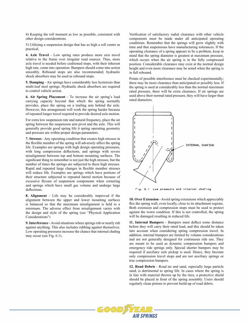
9. Interference - Avoid situations where springs rub or nearly rub against anything. This also includes rubbing against themselves. Low operating pressures increase the chance that internal chafing may occur (see Fig. 6.1).
Verification of satisfactory radial clearance with other vehicle components must be made under all anticipated operating conditions. Remember that the springs will grow slightly with time and that suspensions have manufacturing tolerances. If the operating clearance of a spring appears to be a problem, keep in mind that the spring diameter is greatest at maximum pressure, which occurs when the air spring is in the fully compressed position. Considerable clearance may exist at the normal design height and even more clearance may be noted when the spring is in full rebound.
Points of possible interference must be checked experimentally; there may be more clearance than anticipated-or possibly less. If the spring is used at considerably less than the normal maximum rated pressure, there will be extra clearance. If air springs are used above their normal rated pressure, they will have larger than rated diameters.
10. Over Extension - Avoid spring extensions which appreciably flex the spring wall, even locally, close to its attachment regions. Both extension and compression stops must be used to protect against the worst condition. If this is not controlled, the spring will be damaged resulting in reduced life.
11. Internal Bumpers - Bumpers must deflect some distance before they will carry their rated load, and this should be taken into account when considering spring compression travel. In addition, internal bumpers are limited by volume considerations and are not generally designed for continuous ride use. They are meant to be used as dynamic compression bumpers and emergency ride springs only. Special shorter bumpers may be required if auxiliary axle pickup is used. Hence, they become only compression travel stops and are not auxiliary springs or true compression bumpers.
12. Road Debris - Road tar and sand, especially large particle sand, is detrimental to spring life. In cases where the spring is in line with material thrown up by the tires, a protective shield should be placed in front of the spring assembly. Users should regularly clean pistons to prevent build-up of road debris.

3. AIR SPRING SELECTION PROCEDUREThe initial step in specifying an air spring for a suspension design is to record the known and estimated system parameters. To assist in this, a Data Record Form is provided in Appendix A from which copies can be made.
As a first step, it is important to know whether or not a rubber bumper is required inside the air spring. A rubber bumper is used to support the load when the air spring is not inflated and to prevent damage to the air spring and suspension when extreme compression (jounce) contact is made. It is usually more cost effective from a suspension manufacturer’s standpoint for the compression (jounce) stop to be located external to the air spring.
However, if a suspension manufacturer is supplying a suspension kit to a variety of customers where an external compression (jounce) stop might be removed or left off, then that suspension manufacturer may require an internal compression stop (rubber bumper).
DEFINITION OF VARIABLESAe = Effective Area.
Axc = Maximum axle compression from design / ride height.
Axe = Maximum axle extension from design/ride height.
C = Compression (jounce) stroke of the air spring from its design height.
Ds = Distance from pivot to spring centerline.
Dw = Distance from pivot to wheel centerline or point of applied load.
d = Diameter of the space available at the air spring location.
DH = The specified design height of the air spring chosen from a range of available design heights for that spring (see Engineering Data).
e = Extension (rebound) stroke of the air spring from its design height.
F = The force required to actuate a mass; in a spring, the force that reacts the applied load.
ff = The forced frequency that requires isolation.
fn = The natural frequency of the suspension system (fn = fswhen Lr= 1).
fs = The natural frequency of the air spring (see Engineering Data).
hc = The minimum compressed height for a particular spring application. (hc - min = min compressed height allowable for a given air spring).
he = The maximum extended height for a particular spring application (he- max = max extended height allowable for a given air spring).
K = Spring rate; unless otherwise noted, refers to vertical spring rate +/- 10 mm about design height.
Ld = The design load per air spring in a multiple spring system.
Lr = Lever arm ratio (Lr = Ds / Dw).
N = The number of air springs in a multiple spring system.
ODmax = The maximum outside diameter of an air spring at 100 PSIG; or, the max OD possible for a particular application after allowing for clearance.
P = The air line pressure at the point of air spring application.
S = The total stroke required of the air spring (S = c + e).
W = Total weight of the sprung mass.
SELECTION PROCEDURE
Step OneComplete the Data Record Form (Appendix A) using known or estimated values for system parameters. It is not necessary to have values for all parameters; for example, the selection of design height can be delayed until later in the procedure. Perform the suspension geometry calculations shown on the Data Record Form and record the results. See the Suspension Geometry Section for an explanation of the formulas for lever ratio (Lr), design load (Ld), and natural frequency (fn and fs).
Step TwoDetermine the maximum air spring diameter (ODmax) possible within the available space (d), allowing for clearance. A 1" clearance is recommended, so ODmax = (d - 2"). In some applications, this much clearance may not be necessary; in others, where misalignment is part of the design, additional clearance must be provided.
Step ThreeTurn to the Nominal Operating Range Selection Graph (last page). Draw a horizontal line at the required design load (Ld). Only those air spring groups that are intersected by this line can be considered further. If the height limits for the application (hc and he) are known, use these values and the Assembly Height axis to further reduce the list of potential air spring groups. If hc and he are not known, but required stroke (S) is known, refer to the Usable Stroke Range column in the table below the Nominal Operating Range Selection Graph. Eliminate those groups that do not meet the stroke (S) requirements.
Step FourLook at the “Selection Chart" that is found under Resource Center. Considering only those air spring groups selected in Step Three, use the following procedure to systematically eliminate springs that fail to meet design constraints. The sequence or the procedure itself may need to be modified depending on the information available at this point. (For example, steps 4.1 and 4.2 may be reversed if load range can be used to eliminate springs more quickly than maximum OD. In other cases, Step 4.3, bumper requirements, may be the best starting place.)
4.1. Eliminate all springs where maximum OD @ 100 PSIG is greater than ODmax for the application. List all remaining assembly numbers and their max ODs.
4.2. Next, eliminate all springs where Ld falls outside of the design load range. List all remaining assembly numbers and their load ranges.
4.3. If a bumper is required, use the Bumper Y/N column to eliminate those springs on the remaining list without bumpers. List all remaining assembly numbers.
4.4. If DH (or OH range) is known, use the Design Height Range column to further eliminate springs. If DH (or DH range) is not known, proceed to step 4.5. List all remaining assembly numbers and their design height ranges.
4.5. Next, use the Usable Stroke column to eliminate all springs having usable stroke less than the required stroke (S). List all remaining assembly numbers and their stroke values.
4.6. If the assembly height limits (hc and/or he) for the application are known, compare them to the minimum compressed height (hc-min) and/or maximum extended height (he-max) values for each of the remaining springs. If hc and he are not known, proceed to Step Five. Values for he-max will come either from the Selection Chart or from a physical constraint in the application. Eliminate all those springs where hc is less than hc-min or where he is greater than he-max. List all remaining assembly numbers along with their minimum compressed height and maximum extended height values. If DH is not known, proceed to Step Five. If DH is known, skip Step Five and proceed to Step Six.
Step FiveOpen “Engineering Data" and look at the Dynamic Characteristics table for each spring remaining on the list. List the three tabulated design heights for each spring. Then, referring back to the Selection Chart, list the minimum compressed height (hc-min) and the maximum extended height (he-max) for each spring. Or, if the application has a maximum height constraint, use that for he-max. (Since hc-min and he-max represent physical limits, each assembly number will have only one value for each.) Now refer back to the Data Record Form, and using the calculated values for required spring compression (c) and extension (e), calculate hc and he values for each of the three tabulated design heights for each spring on the current list (hc = DH - c; he = DH + e). Compare the calculated hc and he values to hc-min and he-max for each spring/design height combination. Eliminate all those springs where hc is less than hc-min or where he is greater than he-max. List all remaining assembly numbers along with their hc, hc-min, he, and he-max values.
Step SixIf the desired natural frequency (or desired range) of the suspension system (fn) is known, the desired natural frequency (or range) of the air spring (fs) should have been calculated on the Data Record Form using the following equation:
Refer to the Suspension Geometry Section for further explanation of the above formula.
From the Dynamic Characteristics table in the Engineering Data section for each spring remaining, list the natural frequency (fs) for each spring/design height combination at the
fs =fn
Lr

Data Record Form1. Is an internal rubber bumper required? (Yes/No) Yes
2. The maximum weight (W) to be isolated 20,500 lb
3. The number of air springs (N) to be used 2
4. The diameter (d) of the space available at the air spring location 14.8 in
5. Required design height (DH) of the spring DHmax= 20 - e 13.85max in
6. Air line pressure (P) available 100 PSIG
7. Required natural frequency (fn) of the suspension 1.4-1.6 Hz
8. Maximum axle compression (AXc) 3.5 in
9. Maximum axle extension (AXe) 4.1 in
10. Pivot to wheel distance (Dw) 20 in
11. Pivot to spring distance (Ds) 30 in
12. Lever arm ratio (Lr= Ds/Dw) 1.5
13. Design load per air spring (Ld= W/(N x Lr)) 6833 lb
14. Maximum spring compression required (c = (AXc)(Lr))
5.25 in
15. Maximum spring extension required (e = (AXe)(Lr))
6.15 in
16. Total spring stroke required (S = e + c) 11.40 in
17. Required compressed height of the spring (hc= DH - c) 8.6max in
18. Required extended height of the spring (he= DH + e) 20max in
19. Required natural frequency of the spring (fs= fn / √Lr )
1.14 - 1.31 Hz
20. Environmental conditions (temp., oil, chemicals, etc.)
None special
Step 2 d = 14.8", therefore ODmax = 12.8" or possibly slightly larger, say 13.0", based on judgment that 0.9" clearance will be adequate.
Step 3From the Nominal Operating Range Selection Chart, all large bellows and rolling lobes meet the height requirements at Ld = 6833 lb.
Step 4.1From the Selection Chart, the following large bellows and rolling lobes meet ODmax ≤ 13.0":
Step 4.2From the Selection Chart and the list in Step 4.1, Ld = 6833 falls within the design load range for the following springs:
Step 4.3From the Selection Chart and the list in Step 4.2, the following springs DO have bumpers:
Step 4.4From the Selection Chart and the list in Step 4.3, the following springs have possible design heights less than or equal to 13.85":
Step 4.5From the Selection Chart and the list in Step 4.4, the following springs have strokes ≥11.4":
Assy No.MAX OD, 100 PSIG Assy No.
MAX OD, 100 PSIG
1B9-202 11.0" 1R8-005 8.7"2B9-200 10.3" 1R8-009 8.7"2B9-201 10.3" 1R9-009 9.5"2B9-216 10.3" 1R9-003 9.9"2B9-250 10.3" 1R10-089 11.0"2B9-251 10.3" 1R11-028 11.5"2B9-253 10.3" 1R11-039 11.3"
1B12-313 13.2" 1R12-095 12.7"2B12-309 13.0" 1R12-132 12.7"2B12-425 13.0" 1R12-092 12.7"2B12-429 13.0" 1R12-274 12.7"3B12-304 13.0" 1R12-103 12.7"3B12-305 13.0" 1R12-256 12.7"
Assy No.Design Load
Range Assy No.Design Load
Range1B12-313 1215-8335 lb 1R11-039 1300-7055 lb2B12-309 915-7205 lb 1R12-095 1360-7340 lb2B12-425 915-7205 lb 1R12-132 1400-7815 lb2B12-429 915-7205 lb 1R12-092 1320-7710 lb3B12-304 860-7305 lb 1R12-274 1435-8055 lb3B12-305 860-7305 lb 1R12-103 1325-7730 lb
1R12-256 1390-7695 lb
Assy No. Assy No.2B12-309 1R12-0921R11-039 1R12-2741R12-095 1R12-1031R12-132 1R12-256
Assy No. Design Height Range2B12-309 7.5-9.5"1R11-039 8.0-12.0"1R12-095 7.0-9.0"1R12-132 8.0-10.0"1R12-092 10.5-16.5"1R12-274 11.3-14.3"
Assy No. Usable Stroke1R12-092 13.4"1R12-274 14.7"

Step 4.6For the application, he, is limited to 20". As the following table shows, neither of the two springs remaining can be eliminated because both are capable of meeting the 11.4" stroke requirements with he < 20":
Step 5c = 5.25", e = 6.15". From the Dynamic Characteristic tables and the Selection Chart:
* he-max ≤ 20" is a constraint for this application.
After eliminating all spring/design height combinations where hc ≤ hc -min OR he ≥ he-max, the following remain:
* he-max ≤ 20" is a constraint for this application.
Step 6Target fs = 1.14-1.31 Hz. From the Dynamic Characteristics tables in the Engineering Data section, the remaining spring has the following fs values at Ld = 6833 lb at the applicable design height:
**Linear interpolation sample calculation:
Conclusion: 1R12-092 at 13.3" DH meets fs requirement
Step 7From the Load vs. Deflection @ Constant Pressure curves for 1R12-092 at 13.3" DH, 6833 lb falls between the 80 and 100 PSIG curves at approx. 93 PSIG. Conclusion: OK
Step 8There are no special environmental or other concerns, so it can be concluded that 1R12-092 at 13.3" DH is the optimum spring for the application.
Step 9From the Dynamic Data @ 13.3" DH, curves for 1R12-092, and using hc = 8.05" (DH - c); and he = 19.45" (DH + e), the pressure range is approx. 47 - 219 PSIG. Conclusion: OK.
Sample Problem No. 2 (Different pressure and lever arm ratios; no suspension constraint on extended height)Assume a trailer manufacturer is developing a new suspension for sliders and close-tandems that will give him a 19,000 lb. axle rating with a possible upgrade to a 20,500 lb. rating. The customer requires upward axis travel of 4.1" and downward axle travel of 3.5". The distance from the pivot to the axle is 20", while the distance from the pivot to the desired air spring location is 36". The maximum allowable diameter-without causing interference is 14.8" at the air spring location. Although the vehicle's air compressor can provide up to 120 PSIG, the customer wishes to limit the air line pressure to 80 PSIG for possible flex life gains. The desired natural frequency is 1.4-1.6 Hz. Finally, the customer does not wish to provide a jounce stop external to the air spring. Using two springs per axis, please provide the optimum air spring to meet this customer's requirements.
Step 1:See completed Data Record Form. Note that design height, hc, and he are all unknown. Therefore, stroke (c, e, and S) will provide the major geometrical constraint in addition to diameter. Note also that P is limited to 80 PSIG and that Lr is 1.8 compared to P = 100 PSIG and Lr = 1.5 for Sample Problem No. 1. The larger Lr decreases design load to 5694 lb and increases S to 13.68".
Assy No. hc - min he - max Required S (hc - min + S)1R12-092 7.7" 21.1" 11.4" 19.1"1R12-274 8.1" 22.8" 11.4" 19.5"
Assy No. DH hc - min he - max* hc =DH-c he=DH+e1R12-092 10.5" 7.7" 20.0" 5.25" 16.65"
13.3" 7.7" 20.0" 8.05" 19.45"16.5" 7.7" 20.0" 11.25" 22.65"
1R12-274 11.3" 8.1" 20.0" 6.05" 17.45"12.8" 8.1" 20.0" 7.55" 18.95"14.3" 8.1" 20.0" 9.05" 20.45"
Assy No. DH hc - min he - max* hc =DH-c he=DH+e1R12-092 13.3" 7.7" 20.0" 8.05" 19.45"
Assy No. DH fs at 6833 lb**1R12-092 13.3" 1.233 Hz
7000 lb – 6833 lb 1.23 Hz – fs——————— = ——————7000 lb – 6000 lb 1.23 Hz – 1.25 Hz fs = 1.233 Hz

Data Record Form1. Is an internal rubber bumper required? (Yes/No) Yes
2. The maximum weight (W) to be isolated 20,500 lb
3. The number of air springs (N) to be used 2
4. The diameter (d) of the space available at the air spring location 14.8 in
5. Required design height (DH) of the spring Unknown in
6. Air line pressure (P) available 80 PSIG
7. Required natural frequency (fn) of the suspension 1.4-1.6 Hz
8. Maximum axle compression (AXc) 3.5 in
9. Maximum axle extension (AXe) 4.1 in
10. Pivot to wheel distance (Dw) 20 in
11. Pivot to spring distance (Ds) 36 in
12. Lever arm ratio (Lr= Ds/Dw) 1.8
13. Design load per air spring (Ld= W/(N x Lr)) 5694 lb
14. Maximum spring compression required (c = (AXc)(Lr))
6.30 in
15. Maximum spring extension required (s = (AXe)(Lr))
7.38 in
16. Total spring stroke required (S = e + c) 13.68 in
17. Required compressed height of the spring (hc= DH - c) Unknown in
18. Required extended height of the spring (he= DH + e) Unknown in
19. Required natural frequency of the spring (fs= fn / √Lr )
1.04 - 1.19 Hz
20. Environmental conditions (temp., oil, chemicals, etc.)
None special
Step 2 d = 14.8" therefore ODmax = 12.8" or possibly slightly larger, say 13.0", based on judgment that 0.9" clearance will be adequate.
Step 3From the Nominal Operating Range Selection Chart, only large bellows and rolling lobes meet the requirements for Ld = 5694 lb. And from the table at the bottom of the same page, the Usable Stroke Range column shows that only rolling lobes are capable of at least 13.68" stroke.
Step 4.2From the Selection Chart and the list in Step 4.1, Ln = 5694 falls within the design load range for the following springs:
Step 4.1From the Selection Chart, the following rolling lobes meet ODmax ≤ 13.0":
Step 4.3From the Selection Chart and the list in Step 4.2, the following springs DO have bumpers:
Step 4.4Since DH is not known, proceed to Step 4.5.
Step 4.5From the Selection Chart and the list in Step 4.4, the following springs have strokes ≥11.4":
Assy No.MAX OD, 100 PSIG Assy No.
MAX OD, 100 PSIG
1R8-008 8.7" 1R12-095 12.7"1R8-009 8.7" 1R12-132 12.7"1R9-009 9.5" 1R12-092 12.7"1R9-003 9.5" 1R12-274 12.7"1R10-089 11.0" 1R12-103 12.7"1R11-028 11.5" 1R12-256 12.7"1R11-039 11.7"
Assy No.Design Load
Range Assy No.Design Load
Range1R10-089 1045-5970 lb 1R12-092 1320-7710 lb1R11-028 1115-6795 lb 1R12-274 1435-8055 lb1R11-039 1300-7055 lb 1R12-103 1325-7730 lb1R12-095 1360-7340 lb 1R12-256 1390-7695 lb1R12-132 1400-7815 lb
Assy No. Assy No.1R11-039 1R12-2741R12-095 1R12-1031R12-132 1R12-2561R12-092
Assy No. Usable Stroke1R12-274 14.7"1R12-103 17.6"1R12-256 19.6"

Step 4.6Since hc and he are not known, proceed to Step 5.
Step 5c = 6.30", e = 7.38". From the Dynamic Characteristic tables and the Selection Chart:
After eliminating all spring/design height combinations where hc ≤ hc-min OR he ≥ he-max, the following remain:
* Note: 1R12-274 will be considered at 14.4" DH, which is .10" above the official DH range for that spring.
Step 6Target fs = 1.04-1.19 Hz. From the Dynamic Characteristics tables in the Engineering Data section, the remaining springs have the following fs values at Ld = 5694 lb at the applicable design height:*
*Linear interpolation sample calculation:
Conclusion: The following springs meet fe = 1.04-1.19 at the design heights indicated:
Step 7From the Load vs. Deflection @ Constant Pressure curves for the remaining spring/design height combinations, all of the springs listed in at the end of Step 6 fall below the 80 PSIG curve at Ld = 5694 lb.
Step 8From the Dynamic Data curves at Ld = 5694 lb. and using DH – c and DH + e to define the stroke limits, the remaining springs have the following pressure ranges (c = 6.30", e = 7.38"):
*1R12-274 Max Press value extrapolated from off graph
Conclusion: The pressure ranges are similar for all remaining springs. Looking back to the S and he-max values for the three springs (see Selection Chart or Steps 4.5 and 5), 1R12-103 and 1R12-256 have considerably more stroke capability than is required for the application. The 1R12-274 seems more appropriately sized for the application, so it should be chosen with DH = 14.4", which is close enough to the listed design height range maximum of 14.3".
Step 9There are no special environmental or other concerns, so it can be concluded that 1R12-274 at 14.4" DH is the optimum spring for the application.
Assy No. DH hc - min he - max hc =DH-c he=DH+e1R12-274 11.3" 8.1" 22.8" 5.00" 18.68"
12.8" 8.1" 22.8" 6.50" 20.18"14.3" 8.1" 22.8" 8.00" 21.68"
1R12-103 15.0" 9.5" 27.0" 8.70" 22.38"16.3" 9.5" 27.0" 10.00" 23.68"20.0" 9.5" 27.0" 13.70" 27.38"
1R12-256 16.0" 9.5" 29.1" 9.70" 23.38"18.0" 9.5" 29.1" 11.70" 25.38"20.0" 9.5" 29.1" 13.70" 27.38"
Assy No. DH hc - min he - max hc =DH-c he=DH+e1R12-274 14.4"* 8.1" 22.8" 8.10" 21.68"1R12-103 16.3" 9.5" 27.0" 10.00" 23.68"
20.0" 9.5" 27.0" 13.70" 27.38"1R12-256 16.0" 9.5" 29.1" 9.70" 23.38"
18.0" 9.5" 29.1" 11.70" 25.38"20.0" 9.5" 29.1" 13.70" 27.38"
Assy No. DH fs at 5694 lb**1R12-274 14.4" 1.106 Hz1R12-103 16.3" 1.186 Hz
20.0" 0.906 Hz1R12-256 16.0" 1.126 Hz
18.0" 1.040 Hz20.0" 0.976 Hz
6000 lb – 5694 lb 1.18 Hz – fs——————— = ——————6000 lb – 5000 lb 1.18 Hz – 1.20 Hz fs = 1.186 Hz
Assy No. DH fs at 5694 lb**1R12-274 14.4" 1.106 Hz1R12-103 16.3" 1.186 Hz1R12-256 16.0" 1.126 Hz
18.0" 1.040 Hz
Actual No.
Actual DH
Middle DH
Min Press (est)
Max Press (est)
1R12-274 14.4" 12.8" 38 PSIG 175 PSIG*1R12-103 16.3" 16.3" 37 PSIG 173 PSIG1R12-256 16.0" 18.0" 40 PSIG 155 PSIG
18.0" 18.0" 40 PSIG 155 PSIG

Definition of Variables:fn = Natural frequency of the suspension system
fs = Natural frequency of the air spring
W = Total weight of the sprung mass
N = Number of air springs
Dw = Distance from pivot to wheel centerline or point of applied load
Ds = Distance from pivot to spring centerline
Lr = Lever arm ratio
Ld = Design load per air spring
Formula Explanations:Lr = Ds/Dw ... The lever arm ratio will vary on suspensions depending on whether the air spring is located ahead, behind, or directly over the axle centerline:
Ahead . . . Lr < 1 Behind . . . Lr > 1 Direct . . . . Lr = 1
Ld = W/(N x Lr) ... The load per air spring is dependent on the number of air springs used and the placement of the air springs in the suspension in relation to the axle (lever arm ratio). By designing the suspension with the air spring located behind the axle centerline, you can decrease the load on the spring.
Ahead . . . Ld increases Behind . . . Ld decreases Direct . . . . Ld stays the same
fs = fn / √Lr The natural frequency of the suspension is also dependent on the placement of the air spring in relation to the axle (lever arm ratio). Given a load and design height, one can look up the spring's natural frequency (in the Dynamic Characteristics Table in the Engineering Data Section) and see how the location of the spring would affect the suspension's natural frequency:
Ahead . . . fn decreases Behind . . . fn increases Direct . . . . fn = fs

Do's1. Allow clearance around the maximum diameter of the air
spring to prevent abrasion of the flexible member on other structures. Where misalignment is not intended, one inch of clearance is generally sufficient.
2. Specify air spring assemblies with internal bumpers and/or install external stops to avoid:
a. Compression below the "compressed height without a bumper" for bellows. For rolling lobes & sleeve types, limit the compression to 0.1" above the "compressed height without a bumper".
b. Severe impacting at the "compressed height with no bumper".
c. Operation of vibrating equipment on the air spring assembly when it is deflated.
3. Install extension stops to limit the extension of the air spring to the maximum extended height.
4. When using an external bumper, check the load vs. deflection curve for bumper deflection height to insure compatibility of the air spring bumper and compressed height limits with the application.
5. For application using rolling lobe or sleeve type* air springs, a minimum of approximately 10 PSIG inflation pressure should be maintained. This insures that the flexible member will roll over the piston without buckling. Bellows air springs will maintain their operational configuration at zero pressure.
6. Use pipe dope or teflon tape around air fittings to insure against air leaks.
7. Install air springs with air port on the isolated end whenever possible.
8. Check the notes on the two page Engineering Data layouts of the selected assembly for other valuable information.
9. Consider environmental conditions such as temperature range, chemicals, etc. when choosing a Super-Cushion air spring for air actuation.
ISOLATOR APPLICATION10. Choose an air spring assembly for which the desired
operating height and load are in the design height and design load range at inflation pressures between 20 and 100 PSIG.
11. Where possible, use design heights in the center of the design height range.
12. For increased lateral rate (stability) use 1B type bellows or use restraining cylinders with the rolling lobe and sleeve type assemblies.
13. Inflate with air or nitrogen.
Don'ts1. Do not exceed 200 PSIG internal pressure in compression
or in any other condition.
2. Do not exceed the 100 PSIG maximum inflation pressure without application approval from Veyance Technologies, Inc., manufacturer of Goodyear Engineered Products.
3. Do not exceed the maximum extended height. To do so may cause structural damage to the air spring assembly.
4. Do not put the air spring assembly in torsion. Contact a Goodyear Engineered Products air springs representative if your application requires torsion.
5. Do not permit the Super-Cushion air spring to be compressed below its "compressed height with no bumper" in operation.
6. Do not allow a machine to continue to operate on a deflated air spring assembly. If deflation can occur, an internal bumper will help to protect the air spring assembly.
7. Do not mount a mass on a rolling lobe or sleeve type air spring without providing proper means of lateral stability.
8. Do not exhaust all of the air from a rolling lobe or sleeve type* air spring while attempting to compress it. A minimum of approximately 10 PSIG air pressure should be maintained internally. Not doing so may cause the flex member to buckle instead of rolling over the piston and may cause damage.
9. Do not allow harmful chemicals to contact the air spring.NOTE: The chemicals found in metal cutting processes have been found to be very harmful to the rubber and fabric used in air springs. These fluids are commonly called cutting coolant, and/or, cutting fluid. Do not allow them to contact the air spring.
DO'S AND DON'TS OFDESIGN & APPLICATION
* The 1S3-013 is an exception. It will roll down at 0 PSIG.

In a Super-Cushion air spring the ability to support a load or to produce a linear force depends on the effective area of the air spring.
The relationship between effective area (Ae) in square inches, force or load (L) in pounds, and air pressure (P) in pounds per square inch (gauge) is illustrated in the following equation:
L = P x Ae
It is important to note that the effective area (Ae) decreases with increasing height or increasing stroke of a bellows (B) type air spring. This means that the load-carrying ability of the bellows type decreases with increasing height or stroke.
This can be easily seen by studying the Constant Pressure Data provided in the Engineering Data Section.
Effective area is generally not constant over the entire stroke range for the rolling lobe (R) or sleeve (S) types; however, it is usually more constant over part of the stroke, thus providing a relatively constant load over that part of the stroke for a given pressure. Again, refer to the Constant Pressure Data in the Engineering Data Section.
Installation InstructionsAll air spring applications require adequate support of both upper and lower end components. Although it is recommended to fully support the air springs to the diameter of the attaching end metals, it is not always required. If your application does not allow for full support, contact a Goodyear Engineered Products air springs representative for design assistance.
In the case of arcuate motion, the best results occur when the upper and lower components are parallel at the air spring's bumper contact height. A small reverse angle at this position may be designed in to reduce the angle at maximum spring extension. For bellows, the convolutions must separate as the air spring approaches maximum extension to prevent excessive abrasion. Do Not exceed the Maximum Extended Height of the spring as measured on the outside of the arcuate path.
When designing for the use of air springs, care must be taken to ensure that no sharp edges will contact the flexible member throughout the full travel of the air spring. This must be verified for both maximum inflation and zero pressure operation, especially for rolling lobe and sleeve type rolling lobe springs where the clearance between the meniscus and the piston support surface decreases as the pressure decreases. The space envelope around the air spring must clear the maximum outside diameter of the air spring by two inches (one inch on all sides) to allow for normal growth as well as deformity caused by misalignment.
Excessive loading may occur on the air spring assembly when adequate height clearance is not maintained with external stops. Built-in compression stops (rubber bumpers) are available with various load vs. deflection characteristics. However, external mechanical stops are recommended whenever possible to prevent end metal deformation.
Special cases occur with the three convolution bellows (3B) air springs under certain load and deflection conditions. In order to maintain stability over the entire stroke of a 3B air spring, it must be fully supported to the maximum outside diameter of the air spring. Also, the end retainers must either be recessed approximately 0.75" into the supporting surfaces, or attached with special rubber rings that fit around the outside diameter of the retainers. Contact a Goodyear Engineered Products air springs representative for design assistance.
Special Consideration for Sleeve Type BellowsWhen operating the following air springs at or below the heights listed in the table, caution must be taken to avoid flexible member contact with obstructions. The air springs should either be mounted with a flat plate on both the upper and lower retainers, or on a pedestal (see figure below). Dimensions for the plates and pedestals are specified in the table.
GENERAL DESIGN CONSIDERATIONS
INSTALLATION GUIDELINES
1B5-520 1B6-535 1B8-560Operating Height 2.8" 3.5" 3.3"
Plate Diameter 6.75" 7.25" 9.65"Pedestal Height 1.8" 1.7" 1.5"
Pedestal Diameter 3.25" 4.00" 5.00"

How to Use This Graph:Draw a horizontal line at the desired load per air spring. If the line crosses a region, then the corresponding family of springs is a possibility for the design application. If the stroke and/or
the design height of the application is known, then the spring selection process can be narrowed by drawing vertical lines at the necessary assembly height limits. The resulting line segment must fall entirely within the region to consider that product group for the application.
NOMINAL OPERATING RANGESELECTION GRAPH
PRODUCT GROUP
ASSEMBLY HEIGHT
RANGE (in)
USEABLE STROKE
RANGE (in)
DESIGN HEIGHT
RANGE (in)
FORCE TO COMPRESS RANGE (lb)
LATERAL STABILITY
FREQUENCY RANGE (Hz)
SLEEVE ASSEM's 1.5-10.9 2.1-6.8 2.0-9.0 N/A LOW 1.12-4.30SLEEVE BELLOWS 1.8-9.0 2.0-6.5 2.5-8.0 5-40 LOW TO MODERATE 1.90-3.8LARGE BELLOWS 2.3-18.0 3.6-13.3 3.2-15.0 5-165 MODERATE TO STIFF 1.30-3.0ROLLING LOBES 3.2-29.1 8.6-19.6 6.0-20.0 N/A LOW 0.68-2.23

goodyearrep.com
Aftermarket Parts - Automotive and Commercial Truck, Air Springs, Conveyor Belt - Heavyweight and Lightweight, Home and Garden, Hydraulics, Industrial Hose, Military, Power Transmission Products, Powersports, Rubber Track, Seawing Offshore Oil Hose
The GOODYEAR (and Winged Foot Design) trademark is used by STEMCO LP, under license from The Goodyear Tire & Rubber Company. Goodyear Air Springs are manufactured and sourced exclusively by STEMCO LP or its affiliates.
Data Record Form1. Is an internal rubber bumper required? (Yes/No) ……………
2. The maximum weight (W) to be isolated …………lb
3. The number of air springs (N) to be used ……………
4. The diameter (d) of the space available at the air spring location …………in
5. Required design height (DH) of the spring …………in
6. Air line pressure (P) available ………PSIG
7. Required natural frequency (fn) of the suspension …………Hz
8. Maximum axle compression (AXc) …………in
9. Maximum axle extension (AXe) …………in
10. Pivot to wheel distance (Dw) …………in
11. Pivot to spring distance (Ds) …………in
12. Lever arm ratio (Lr= Ds/Dw) ……………
13. Design load per air spring (Ld= W/(N x Lr)) …………lb
14. Maximum spring compression required (c = (AXc)(Lr)) …………in
15. Maximum spring extension required (s = (AXe)(Lr)) …………in
16. Total spring stroke required (S = e + c) …………in
17. Required compressed height of the spring (hc= DH - c) …………in
18. Required extended height of the spring (he= DH + e) …………in
19. Required natural frequency of the spring (fs= fn / √Lr ) …………Hz
20. Environmental conditions (temp., oil, chemicals, etc.) ……………
Appendix A