Air Handling Systems - rg-cloud.com E.pdf · Use external static pressure column found in Fan...
30
CANADA: 100% OUTSIDE AIR ONLY Air Handling Systems Cooling, Energy Recovery, Heating & Pressurization 1.800.536.3461 www.rapidengineering.com 4000-Series Dimension and Selection Guide
Transcript of Air Handling Systems - rg-cloud.com E.pdf · Use external static pressure column found in Fan...

CANADA: 100% OUTSIDE AIR ONLY
Air Handling SystemsCooling, Energy Recovery, Heating & Pressurization
1.800.536.3461www.rapidengineering.com
4000-Series
Dimension and Selection Guide
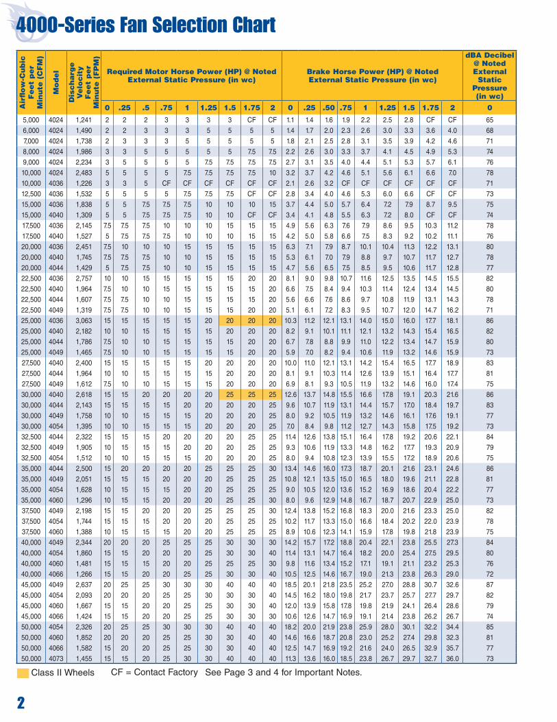
4000-Series Fan Selection ChartA
irfl
ow
-Cu
bic
F
ee
t p
er
M
inu
te (
CF
M)
Mo
de
l
Dis
ch
arg
e
Ve
loc
ity
Fe
et
pe
r
Min
ute
(F
PM
)
Required Motor Horse Power (HP) @ Noted External Static Pressure (in wc)
Brake Horse Power (HP) @ Noted External Static Pressure (in wc)
dBA Decibel @ Noted External
Static Pressure (in wc)
0 .25 .5 .75 1 1.25 1.5 1.75 2 0 .25 .50 .75 1 1.25 1.5 1.75 2 0
5,000 4024 1,241 2 2 2 3 3 3 3 CF CF 1.1 1.4 1.6 1.9 2.2 2.5 2.8 CF CF 65
6,000 4024 1,490 2 2 3 3 3 5 5 5 5 1.4 1.7 2.0 2.3 2.6 3.0 3.3 3.6 4.0 68
7,000 4024 1,738 2 3 3 3 5 5 5 5 5 1.8 2.1 2.5 2.8 3.1 3.5 3.9 4.2 4.6 71
8,000 4024 1,986 3 3 5 5 5 5 5 7.5 7.5 2.2 2.6 3.0 3.3 3.7 4.1 4.5 4.9 5.3 74
9,000 4024 2,234 3 5 5 5 5 7.5 7.5 7.5 7.5 2.7 3.1 3.5 4.0 4.4 5.1 5.3 5.7 6.1 76
10,000 4024 2,483 5 5 5 5 7.5 7.5 7.5 7.5 10 3.2 3.7 4.2 4.6 5.1 5.6 6.1 6.6 7.0 78
10,000 4036 1,226 3 3 5 CF CF CF CF CF CF 2.1 2.6 3.2 CF CF CF CF CF CF 71
12,500 4036 1,532 5 5 5 5 7.5 7.5 7.5 CF CF 2.8 3.4 4.0 4.6 5.3 6.0 6.6 CF CF 73
15,000 4036 1,838 5 5 7.5 7.5 7.5 10 10 10 15 3.7 4.4 5.0 5.7 6.4 7.2 7.9 8.7 9.5 75
15,000 4040 1,309 5 5 7.5 7.5 7.5 10 10 CF CF 3.4 4.1 4.8 5.5 6.3 7.2 8.0 CF CF 74
17,500 4036 2,145 7.5 7.5 7.5 10 10 10 15 15 15 4.9 5.6 6.3 7.6 7.9 8.6 9.5 10.3 11.2 78
17,500 4040 1,527 5 7.5 7.5 7.5 10 10 10 15 15 4.2 5.0 5.8 6.6 7.5 8.3 9.2 10.2 11.1 76
20,000 4036 2,451 7.5 10 10 10 15 15 15 15 15 6.3 7.1 7.9 8.7 10.1 10.4 11.3 12.2 13.1 80
20,000 4040 1,745 7.5 7.5 7.5 10 10 15 15 15 15 5.3 6.1 7.0 7.9 8.8 9.7 10.7 11.7 12.7 78
20,000 4044 1,429 5 7.5 7.5 10 10 15 15 15 15 4.7 5.6 6.5 7.5 8.5 9.5 10.6 11.7 12.8 77
22,500 4036 2,757 10 10 15 15 15 15 15 20 20 8.1 9.0 9.8 10.7 11.6 12.5 13.5 14.5 15.5 82
22,500 4040 1,964 7.5 10 10 15 15 15 15 15 20 6.6 7.5 8.4 9.4 10.3 11.4 12.4 13.4 14.5 80
22,500 4044 1,607 7.5 7.5 10 10 15 15 15 15 20 5.6 6.6 7.6 8.6 9.7 10.8 11.9 13.1 14.3 78
22,500 4049 1,319 7.5 7.5 10 10 15 15 15 20 20 5.1 6.1 7.2 8.3 9.5 10.7 12.0 14.7 16.2 71
25,000 4036 3,063 15 15 15 15 15 20 20 20 20 10.3 11.2 12.1 13.1 14.0 15.0 16.0 17.7 18.1 86
25,000 4040 2,182 10 10 15 15 15 15 20 20 20 8.2 9.1 10.1 11.1 12.1 13.2 14.3 15.4 16.5 82
25,000 4044 1,786 7.5 10 10 15 15 15 15 20 20 6.7 7.8 8.8 9.9 11.0 12.2 13.4 14.7 15.9 80
25,000 4049 1,465 7.5 10 10 15 15 15 15 20 20 5.9 7.0 8.2 9.4 10.6 11.9 13.2 14.6 15.9 73
27,500 4040 2,400 15 15 15 15 15 20 20 20 20 10.0 11.0 12.1 13.1 14.2 15.4 16.5 17.7 18.9 83
27,500 4044 1,964 10 10 15 15 15 15 20 20 20 8.1 9.1 10.3 11.4 12.6 13.9 15.1 16.4 17.7 81
27,500 4049 1,612 7.5 10 10 15 15 15 20 20 20 6.9 8.1 9.3 10.5 11.9 13.2 14.6 16.0 17.4 75
30,000 4040 2,618 15 15 20 20 20 20 25 25 25 12.6 13.7 14.8 15.5 16.6 17.8 19.1 20.3 21.6 86
30,000 4044 2,143 15 15 15 15 20 20 20 20 25 9.6 10.7 11.9 13.1 14.4 15.7 17.0 18.4 19.7 83
30,000 4049 1,758 10 10 15 15 15 20 20 20 25 8.0 9.2 10.5 11.9 13.2 14.6 16.1 17.6 19.1 77
30,000 4054 1,395 10 10 15 15 15 20 20 20 25 7.0 8.4 9.8 11.2 12.7 14.3 15.8 17.5 19.2 73
32,500 4044 2,322 15 15 15 20 20 20 20 25 25 11.4 12.6 13.8 15.1 16.4 17.8 19.2 20.6 22.1 84
32,500 4049 1,905 10 15 15 15 20 20 20 25 25 9.3 10.6 11.9 13.3 14.8 16.2 17.7 19.3 20.9 79
32,500 4054 1,512 10 10 15 15 15 20 20 20 25 8.0 9.4 10.8 12.3 13.9 15.5 17.2 18.9 20.6 75
35,000 4044 2,500 15 20 20 20 20 25 25 25 30 13.4 14.6 16.0 17.3 18.7 20.1 21.6 23.1 24.6 86
35,000 4049 2,051 15 15 15 20 20 20 25 25 25 10.8 12.1 13.5 15.0 16.5 18.0 19.6 21.1 22.8 81
35,000 4054 1,628 10 15 15 15 20 20 25 25 25 9.0 10.5 12.0 13.6 15.2 16.9 18.6 20.4 22.2 77
35,000 4060 1,296 10 15 15 20 20 20 25 25 30 8.0 9.6 12.9 14.8 16.7 18.7 20.7 22.9 25.0 73
37,500 4049 2,198 15 15 20 20 20 25 25 25 30 12.4 13.8 15.2 16.8 18.3 20.0 21.6 23.3 25.0 82
37,500 4054 1,744 15 15 15 20 20 20 25 25 25 10.2 11.7 13.3 15.0 16.6 18.4 20.2 22.0 23.9 78
37,500 4060 1,388 10 15 15 15 20 20 25 25 25 8.9 10.6 12.3 14.1 15.9 17.8 19.8 21.8 23.9 75
40,000 4049 2,344 20 20 20 25 25 25 30 30 30 14.2 15.7 17.2 18.8 20.4 22.1 23.8 25.5 27.3 84
40,000 4054 1,860 15 15 20 20 20 25 30 30 40 11.4 13.1 14.7 16.4 18.2 20.0 25.4 27.5 29.5 80
40,000 4060 1,481 15 15 15 20 20 25 25 25 30 9.8 11.6 13.4 15.2 17.1 19.1 21.1 23.2 25.3 76
40,000 4066 1,266 15 15 20 20 25 25 30 30 40 10.5 12.5 14.6 16.7 19.0 21.3 23.8 26.3 29.0 72
45,000 4049 2,637 20 25 25 30 30 30 40 40 40 18.5 20.1 21.8 23.5 25.2 27.0 28.8 30.7 32.6 87
45,000 4054 2,093 20 20 20 25 25 30 30 30 40 14.5 16.2 18.0 19.8 21.7 23.7 25.7 27.7 29.7 82
45,000 4060 1,667 15 15 20 20 25 25 30 30 40 12.0 13.9 15.8 17.8 19.8 21.9 24.1 26.4 28.6 79
45,000 4066 1,424 15 15 20 20 25 25 30 30 30 10.6 12.6 14.7 16.9 19.1 21.4 23.8 26.2 26.7 74
50,000 4054 2,326 20 25 25 30 30 30 40 40 40 18.2 20.0 21.9 23.8 25.9 28.0 30.1 32.2 34.4 85
50,000 4060 1,852 20 20 20 25 25 30 30 40 40 14.6 16.6 18.7 20.8 23.0 25.2 27.4 29.8 32.3 81
50,000 4066 1,582 15 20 20 25 25 30 30 40 40 12.5 14.7 16.9 19.2 21.6 24.0 26.5 32.9 35.7 77
50,000 4073 1,455 15 15 20 25 30 30 40 40 40 11.3 13.6 16.0 18.5 23.8 26.7 29.7 32.7 36.0 73
Class II Wheels See Page 3 and 4 for Important Notes.CF = Contact Factory
2

Class II Wheels*Denotes MUA configuration only See Page 3 and 4 for Important Notes.CF = Contact Factory
3
4000-Series Fan Selection ChartA
irfl
ow
-Cu
bic
F
ee
t p
er
M
inu
te (
CF
M)
Mo
de
l
Dis
ch
arg
e
Ve
loc
ity
Fe
et
pe
r
Min
ute
(F
PM
)
Required Motor Horse Power (HP) @ Noted External Static Pressure (in wc)
Brake Horse Power (HP) @ Noted External Static Pressure (in wc)
dBA Decibel @ Noted External
Static Pressure (in wc)
0 .25 .5 .75 1 1.25 1.5 1.75 2 0 .25 .50 .75 1 1.25 1.5 1.75 2 0
55,000 4060 2,037 20 25 25 25 30 30 40 40 40 18.1 20.0 21.9 23.9 26.0 28.1 30.1 32.3 34.6 83
55,000 4066 1,741 20 20 20 25 25 30 30 40 40 15.0 17.1 19.2 21.2 23.5 25.7 28.1 30.4 32.8 80
55,000 4073 1,600 20 20 25 25 30 30 30 CF CF 16.1 18.4 20.8 23.2 25.6 28.2 30.8 CF CF 75
60,000 4060 2,222 25 25 30 30 40 40 40 40 40 22.0 24.1 26.2 28.3 30.5 32.7 35.0 37.3 39.5 85
60,000 4066 1,899 20 25 25 25 30 30 40 40 40 18.1 20.2 22.4 24.7 27.0 29.4 31.8 34.3 36.9 81
60,000 4073 1,745 20 25 25 30 30 40 40 40 40 18.6 21.0 23.5 26.1 28.6 31.3 34.1 36.9 39.7 77
60,000 4080 1,241 20 20 25 25 30 CF CF CF CF 16.5 19.1 21.7 24.5 27.4 CF CF CF CF 72
65,000 4066 2,057 25 25 30 30 40 40 40 40 50 21.6 23.9 26.2 28.6 31.1 33.6 36.1 38.8 41.4 83
65,000 4073 1,891 25 25 30 30 40 40 40 50 50 21.3 23.8 26.5 29.2 31.9 34.7 37.6 40.5 43.5 79
65,000 4080 1,345 20 25 25 30 40 40 CF CF CF 18.5 21.3 24.0 27.0 30.2 33.0 CF CF CF 74
70,000 4066 2,215 30 30 40 40 40 40 50 50 50 25.5 27.9 30.4 33.0 35.6 38.2 40.9 43.5 46.4 85
70,000 4073 2,036 25 30 30 40 40 40 50 50 50 24.5 27.1 29.8 32.7 35.6 38.5 41.5 44.5 47.6 81
70,000 4080 1,448 25 25 30 30 40 40 40 50 CF 20.7 23.6 26.6 29.5 32.7 35.9 39.1 42.4 CF 76
75,000 4066 2,374 30 40 40 40 50 50 50 50 60 30.0 32.6 35.2 37.9 40.6 43.4 46.2 49.1 52.0 87
75,000 4073 2,182 30 40 40 40 40 50 50 50 60 27.9 30.7 33.6 36.4 39.5 42.6 45.7 48.9 52.1 83
75,000 4080 1,552 25 30 30 40 40 40 50 50 50 23.2 26.3 29.4 32.5 35.8 39.1 42.4 45.9 49.4 78
75,000 4089 1,552 25 25 30 40 40 CF CF CF CF 21.3 24.5 27.9 31.3 34.8 CF CF CF CF 73
80,000 4066 2,532 40 40 50 50 50 50 60 60 60 35.1 37.8 40.6 43.4 46.3 49.2 52.1 55.1 58.2 88
80,000 4073 2,327 40 40 40 50 50 50 60 60 60 31.7 34.6 37.6 40.7 43.7 47.0 50.3 53.6 56.9 85
80,000 4080 1,655 30 30 40 40 40 50 50 50 60 26.0 29.0 33.9 35.5 38.9 42.3 45.8 49.4 52.9 79
80,000 4089 1,655 25 30 40 40 40 50 CF CF CF 23.5 26.9 30.3 33.9 37.6 41.3 CF CF CF 75
85,000 4073 2,473 40 40 50 50 50 60 60 60 75 36.0 39.1 42.3 45.5 48.7 51.9 55.4 58.8 62.4 86
85,000 4080 1,759 30 40 40 40 50 50 50 60 60 29.0 32.2 35.5 38.9 42.4 46.0 49.6 53.2 57.1 81
85,000 4089 1,759 30 30 40 40 50 50 50 60 CF 25.8 29.4 33.0 36.6 40.4 44.3 48.3 52.3 CF 76
90,000 4073 2,618 50 50 50 60 60 60 75 75 75 40.7 43.9 47.2 50.5 53.9 57.4 60.7 64.3 68.0 87
90,000 4080 1,862 40 40 40 50 50 50 60 60 75 32.4 35.7 39.2 42.6 46.3 50.0 53.8 57.6 61.5 82
90,000 4089 1,862 30 40 40 40 50 50 60 60 60 28.3 32.0 35.8 39.6 43.5 47.5 51.6 55.8 60.0 78
95,000 4073 2,764 50 50 60 60 60 75 75 75 75 45.9 49.2 52.6 56.1 59.6 63.2 66.8 70.5 74.1 88
95,000 4080 1,966 40 40 50 50 60 60 60 75 75 35.9 39.4 43.0 46.6 50.3 54.2 58.1 62.1 66.1 84
95,000 4089 1,966 40 40 40 50 50 60 60 60 75 31.3 35.0 38.9 42.9 46.9 51.0 55.3 59.5 64.0 79
100,000 4080 2,069 40 50 50 60 60 60 75 75 75 39.8 43.5 47.2 51.0 54.9 58.7 62.8 66.9 71.1 85
100,000 4089 2,069 40 40 50 50 60 60 60 75 75 34.3 38.1 42.2 46.2 50.5 54.7 59.0 66.2 68.0 80
110,000 4080 2,279 50 60 60 60 75 75 75 100 100 46.2 50.4 54.4 59.4 64.0 68.7 73.6 78.5 83.5 88
110,000 4089 2,276 50 50 50 60 60 75 75 75 100 41.1 45.2 49.5 53.8 58.3 62.8 67.5 72.2 76.9 83
120,000 4080 2,483 60 75 75 75 100 100 100 100 100 57.0 61.6 66.1 70.9 75.9 80.9 86.1 91.25 96.5 90
120,000 4089 2,483 50 60 60 75 75 75 100 100 100 49.0 53.4 57.9 62.5 67.1 71.9 76.8 81.9 86.9 85
130,000 4089 2,690 60 75 75 75 100 100 100 100 100 58.0 62.7 67.5 72.4 77.4 82.2 87.4 92.7 98.0 87
140,000 4089* 2,897 75 75 100 100 100 100 100 125 125 64.8 70.3 75.9 81.6 87.4 93.4 99.4 105.6 111.9 90
150,000 4089* 3,103 100 100 100 100 125 125 125 125 125 80.0 85.3 90.6 96.0 101.5 107.1 112.8 118.5 124.4 91
IMPORTANT NOTES:Sound levels are in dBA at 5' from the discharge opening. This figure does not account for attenuation, additional noise or directivity factors. Motor horsepower required includes both the running HP and the starting torque requirements. HP can be greater than the standard fan curve charts. Brake HP does not include drive losses. For external static pressure greater than 2", contact your local representative or Rapid Engineering LLC. For operation in altitudes exceeding 2000' above sea level, contact the factory. The recommended motor horsepowers shown for the Fan Selection Chart include fan and burner static pressure only (internal equipment static pressure). Other cabinet options could add static pressure and should be included in the external static pressure used to select motor horsepower. See the Static Pressure Drops on page 4 for the external static pressures that should be added for selected options.

4
Static Pressure Drops for Options
120 °F temperature rise is not ETL listed. Greater than 100 °F temperature rise is not ETL listed when LPG is the fuel.
Airflow -Cubic Feet per Minute
(CFM)
Burner Capacity Chart
Gas Flow - Cubic Feet per Hour (CFH) for Stated Temperature Rise
40 °F 50 °F 60 °F 70 °F 80 °F 90 °F 100 °F 110 °F 120 °F5,000 375 375 375 375 750 750 750 750 7506,000 375 375 750 750 750 750 750 750 1,1257,000 375 375 750 750 750 750 750 1,125 1,1258,000 375 750 750 750 750 1,125 1,125 1,125 1,1259,000 750 750 750 750 750 1,125 1,125 1,125 1,50010,000 750 750 750 750 1,125 1,125 1,125 1,500 1,50012,500 750 750 1,125 1,125 1,125 1,500 1,500 1,500 1,87515,000 750 1,125 1,125 1,125 1,500 1,500 1,875 1,875 2,25017,500 750 1,125 1,125 1,500 1,500 1,875 1,875 2,250 2,25020,000 1,125 1,125 1,500 1,500 1,875 2,250 2,250 2,625 2,62522,500 1,125 1,500 1,500 1,875 2,250 2,250 2,625 2,625 3,00025,000 1,125 1,500 1,875 1,875 2,250 2,625 2,625 3,000 3,37530,000 1,500 1,875 2,250 2,250 2,625 3,000 3,375 3,750 4,12535,000 1,500 1,875 2,250 2,625 3,000 3,375 3,750 4,125 4,50040,000 1,875 2,250 2,625 3,000 3,375 4,125 4,500 4,875 5,25045,000 2,250 2,625 3,000 3,375 4,125 4,500 4,875 5,250 6,00050,000 2,250 2,625 3,375 3,750 4,500 4,875 5,250 6,000 6,37555,000 2,625 3,000 3,750 4,125 4,875 5,250 6,000 6,375 7,12560,000 2,625 3,375 4,125 4,500 5,250 6,000 6,375 7,125 7,87565,000 3,000 3,750 4,125 4,875 5,625 6,375 7,125 7,500 8,62570,000 3,000 3,750 4,500 5,250 6,000 6,750 7,500 8,250 9,00075,000 3,375 4,125 4,875 5,625 6,375 7,125 7,875 9,000 9,75080,000 3,375 4,500 5,250 6,000 6,750 7,875 8,625 9,375 10,50085,000 3,750 4,500 5,625 6,375 7,500 8,250 9,000 10,125 10,87590,000 4,125 4,875 6,000 6,750 7,875 8,625 9,750 10,875 11,62595,000 4,125 5,250 6,000 7,125 8,250 9,375 10,125 11,250 12,375100,000 4,500 5,250 6,375 7,500 8,625 9,750 10,875 12,000 13,125110,000 4,875 6,000 7,125 8,250 9,375 10,500 12,000 13,125 14,250120,000 5,250 6,375 7,875 9,000 10,500 11,625 13,125 14,250 15,375130,000 5,625 7,125 8,250 9,750 11,250 12,750 13,875 15,375 16,875150,000 6,375 7,875 9,750 11,250 12,750 14,625 16,125 17,625 19,500
Burner Selection Chart
Description in wc
Moisture Limiter For Horizontal Inlet Hood 0.10
Aluminum Mesh Filters For Horizontal Inlet Hood 0.15
Upright Stand with Polyester Filters (FR) 0.25
Outside Air Filter Section, No Filters 0
Filtered Mixing Box, No Filters 0
Filters - Polyester 0.25
Filters - Aluminum Mesh 0.15
Filters - 30% Pleated 0.25
Custom Filter Options (Bag, Cartridge, HEPA) CF
Evaporative Cooling Section (ECM) 0.25
Evaporative Cooling Section (ECM-D) 0.50
Cooling Coil Section 0.10
Cooling Coil CF
Description in wc
Damper - Inlet 0.05
Damper - Low Leak 0.05
Damper - Discharge 0.10
Damper - Discharge, Low Leak 0.10
End Discharge 0.20
Discharge Plate 0.05
Discharge Head - One Way 0.10
Discharge Head - Three Way 0.10
Discharge Head - Four Way 0.05
Horizontal Inlet Hood 0.00
Horizontal Inlet Plenum 0.10
Upright Inlet Plenum Base 0.05
Energy Recovery See Pg. 10
IMPORTANT NOTE: Calculate the static pressure for selected cabinet options plus any ductwork. Use external static pressure column found in Fan Selection Chart on pages 2-3 to determine motor horsepower.

5
DIRECTIONS:• Select a point on the chart that represents the intersection of the inlet gas pressure and the unit cubic feet per hour (CFH).• Select the manifold size to the right of this point. • For inlet supply gas pressure exceeding 5 PSI, an additional gas regulator is required.
Manifold Selection Charts
43.0
35.0
27.0
19.0
11.0
45.0
37.0
29.0
21.0
13.0
47.0
39.0
31.0
23.0
15.0
49.0
41.0
33.0
25.0
17.0
0 1000 2000 3000 4000 5000 6000 7000 8000 9000 10000 11000 12000 13000 14000
Required Gas Flow in Cubic Feet per Hour (CFH)
Req
uire
d G
as P
ress
ure
at M
anifo
ld In
let (
in w
c)
3” with 4” ModulatingRegulating Valve
1.25”
1.5”
2”
2.5”
3”
4”
1”
= Gas Train Size
39.0
31.0
23.0
15.0
7.0
41.0
33.0
25.0
17.0
9.0
43.0
35.0
27.0
19.0
11.0
45.0
37.0
29.0
21.0
13.0
0 1000 2000 3000 4000 5000 6000 7000 8000 9000 10000 11000 12000 13000 14000
Req
uire
d G
as P
ress
ure
at M
anifo
ld In
let (
in w
c)
3” with 4” ModulatingRegulating Valve
Required Gas Flow in Cubic Feet per Hour (CFH) = Gas Train Size
1”
1.25”
1.5”
2”2.5”
3”
4”
Natural Gas Flow vs. Required Inlet Pressure using an NP1-LE burner
Natural Gas Flow vs. Required Inlet Pressure using an NP2-LE burner

6
Evaporative Cooling
* Bleed-off and recirculation rates will vary with locale, water quality and chemical treatment program. These values are only for approximation.IMPORTANT NOTE: Refer to saturation efficiency table below.
Formulas
1 Leaving Dry Bulb = ODB – [SE* x (ODB - OWB)]
2Leaving Wet Bulb = Entering Wet Bulb (actually, it’s slightly less than the entering wet bulb, but is normally considered equal.)
3 Wet Bulb Depression = ODB – OWB
4 Evaporation Rate (GPH) = CFM x WBD x SE/8050
5 Bleed-off Rate = approximately 20% of evaporation rate*
6 Recirculation Rate = approximately 3 times evaporation rate*
Abbreviations
CFM Cubic Feet Per Minute
GPH Gallons Per Hour
IDB Indoor (Design) Dry Bulb Temperature
LDB Leaving Dry Bulb Temperature
LWB Leaving Wet BulbTemperature
ODB Outdoor (Design) Dry Bulb Temperature
OWB Outdoor (Design) Wet Bulb Temperature
SE Saturation Efficiency of the Evaporative Media
WBD Wet Bulb Depression
Wet BulbDepression
(°F)
Evaporation Rate - Gallons per Hour (GPH) Per 1,000 Cubic Feet per Minute (CFM) at Stated Saturation Efficiency
0.80 0.82 0.84 0.86 0.88 0.90 0.92 0.94 0.96 0.98
5 0.50 0.51 0.52 0.53 0.55 0.56 0.57 0.58 0.60 0.61
10 0.99 1.02 1.04 1.07 1.09 1.12 1.14 1.17 1.19 1.22
15 1.49 1.53 1.56 1.60 1.64 1.68 1.71 1.75 1.79 1.8320 1.99 2.04 2.09 2.14 2.19 2.23 2.28 2.33 2.38 2.4325 2.48 2.55 2.61 2.67 2.73 2.79 2.86 2.92 2.98 3.04
30 2.98 3.05 3.13 3.20 3.28 3.35 3.43 3.50 3.58 3.65
35 3.48 3.56 3.65 3.74 3.82 3.91 4.00 4.08 4.17 4.26
40 3.97 4.07 4.17 4.27 4.37 4.47 4.57 4.67 4.77 4.87
45 4.47 4.58 4.69 4.80 4.92 5.03 5.14 5.25 5.36 5.48
Suggested Air Changes Per Hour(Air Change Method)
Leaving Air Temperature
(°F DB)
Indoor Air Temperature
Above Ambient (°F)*
Air Changes/ Hour**
78° 20° 30 - 60
76° - 78° 15° - 20° 20 - 40
74° - 76° 10° - 15° 15 - 30
72° - 74° 5° - 15° 12 - 20
< 72° < 10° 10 - 15
* For existing buildings: Average amount indoor temperature exceeds ambient outdoor temperature when evaporative cooling is not in use.
** Experience has shown that significant benefit can be achieved with 10-15 Air Changes per Hour (AC/Hr) through the low-est 12' of the facility. For a 24' high building, this would mean 5-6 Air Changes per Hour (AC/Hr) for the entire volume. This will vary by application.
Airflow-Feet per Minute(FPM)
Saturation Efficiency at Stated Media Depth (in)
6" 8" 12" 18" 24"400 0.71 0.81 0.90 0.98 0.99
500 0.68 0.79 0.89 0.98 0.99
600 0.66 0.77 0.88 0.97 0.99
700 0.64 0.75 0.87 0.97 0.98
Airflow-Feet per Minute(FPM)
Static Pressure Drop (in wc) at Stated Media Depth (in)
6" 8" 12" 18" 24"
400 0.06 0.09 0.14 0.19 0.24
500 0.09 0.14 0.21 0.30 0.39
600 0.13 0.20 0.30 0.42 0.55
700 0.23 0.31 0.44 0.62 0.80
• Heat of vaporizaton = 1043 BTU/lb• Weight of water = 8.34 lb./Gallon• GPH = CFM x WBD x SE x 1.08/1043/8.34 = CFM x WBD x SE/8050
IMPORTANT NOTE: Moisture limiter pressure drop is added for face velocities greater than 600 Feet per Minute (FPM). Rapid Engineering LLC's stan-dard media thickness equals 12".

Evaporative Cooling
Wet BulbDepression
(°F)
Temperature Drop (°F) For Stat-ed Media Depth (in)
6" 8" 12" 18" 24"10.0 6.8 7.9 8.9 9.8 9.912.5 8.5 9.8 11.1 12.2 12.315.0 10.2 11.8 13.3 14.6 14.817.5 11.9 13.8 15.6 17.1 17.320.0 13.6 15.8 17.8 19.5 19.722.5 15.3 17.7 20.0 21.9 22.225.0 17.0 19.7 22.2 24.4 24.727.5 18.7 21.7 24.4 26.8 27.230.0 20.4 23.6 26.7 29.3 29.632.5 22.1 25.6 28.9 31.7 32.135.0 23.8 27.6 31.1 34.1 34.637.5 25.5 29.5 33.3 36.6 37.0
40.0 27.2 31.5 35.6 39.0 39.5
Leaving Dry Bulb Temperature Drop [Average]
Temperature (°F)Density Ratio For Stated Elevation (ft/in HG)
0/29.92
1,000/28.86
2,000/26.82
3,000/26.82
4,000/25.84
5,000/24.90
6,000/23.98
7,000/23.09
8,000/22.22
9,000/21.39
10,000/20.58
68° 1.00 0.97 0.93 0.90 0.87 0.84 0.80 0.77 0.75 0.72 0.6970° 1.00 0.96 0.93 0.90 0.86 0.83 0.80 0.77 0.74 0.71 0.6972° 1.00 0.96 0.93 0.89 0.86 0.83 0.80 0.77 0.74 0.71 0.6974° 0.99 0.96 0.92 0.89 0.86 0.83 0.80 0.77 0.74 0.71 0.6876° 0.99 0.95 0.92 0.89 0.85 0.82 0.79 0.76 0.73 0.71 0.6878° 0.99 0.95 0.92 0.88 0.85 0.82 0.79 0.76 0.73 0.70 0.6880° 0.98 0.95 0.91 0.88 0.85 0.82 0.79 0.76 0.73 0.70 0.68
Air Density Ratio
IMPORTANT NOTE: Rapid Engineering LLC's standard media thickness equals 12".
IMPORTANT NOTE: Table to be used when calculating total tonnage of cooling adjusted for elevation.
OA
BD
UD
LD/RD
ELECTRICALCONNECTION
GAS CONNECTIONBR
CE
OA
RD
BD/UD
CE
FJ
LD
FJ
AD1AD2
AD1AD2
PLAN VIEW
RIGHT SIDE VIEW
FAN SECTION BURNER SECTION COIL SECTION(OPTIONAL)
EVAPORATIVECOOLER
(OPTIONAL)
ENERGYRECOVERYSECTION
(OPTIONAL)
FILTER SECTION
(OPTIONAL)
INLET PLENUM(OPTIONAL)
INLET HOOD(OPTIONAL)OR
A
66”
B
IMPORTANT NOTE: Evaporative Cooling Section is 42". Transition section is 24". Total length is 66". Applicable for MUA/AM/VAV styles only.
IMPORTANT NOTES: • For unit dimensions, see pages 12, 14, 18. For legends, see pages 13, 15, 17, 19.• All dimensions are in inches and all weights are in pounds.• All dimensions and weights are subject to change without notice.
Applicable Cabinet
Model 550 FPM
MaxCFM
Applicable Cabinet
Model 750 FPM
MaxCFM
Dimensions
A B
4024 ECM24 4,000 4024 ECM24D 5,800 40 40
4024-4036 ECM36 10,000 4036 ECM36D 13,700 58 58
4036 ECM40 12,000 4036-4040 ECM40D 16,600 63 63
4036 ECM44 14,500 4036-4044 ECM44D 19,600 69 69
4036-4040 ECM49 17,700 4036-4049 ECM49D 24,300 76 76
4036-4049 ECM54 23,000 4044-4054 ECM54D 31,200 85 85
4040-4049 ECM60 28,000 4049-4060 ECM60D 38,500 94 94
4044-4054 ECM66 31,600 4049-4066 ECM66D 43,100 104 96
4044-4054 ECM73 34,100 4054-4066 ECM73D 46,600 112 96
4054-4066ECM80 / ECM89
48,000 4066-4080ECM-80D /
ECM89D65,300 131 112
7

8
Airflow -Cubic Feet per Minute
(CFM)
Compatible Cabinet
Sizes
Range OfAvailable
TonsOf Cooling
Quantity Of Coils Square Feet
Fin Area (L x H)
Of Each Coil (in)
Coil FaceVelocity Width Height Length
Low High CC DD EE
3,000-7,000 4024 8-35 1 13.8 33 x 60 218 509 68 40 72
7,001-10,000 4024 18-50 1 18.0 36 x 72 389 556 80 44 72
10,001-20,000 4036-4040 25-100 2 38.3 27 x 102 261 523 110 65 72
20,001-27,500 4036-4044 50-138 2 52.5 35 x 108 381 524 116 80 78
27,501-30,000 4040-4049 69-150 2 61.2 39 x 113 449 490 121 90 7830,001-35,000 4049-4060 75-175 2 70.0 41 x 123 428 500 131 96 8435,001-50,000 4060-4073 88-250 2 93.8 45 x 150 373 533 158 105 84
50,001-60,000 4066-4080 125-300 3 106.5 36 x 142 469 563 150 126 102
60,001-65,000 4073-4089 150-325 3 117.0 36 x 156 513 556 164 126 102
Mechanical Cooling
Airflow -Cubic Feet per Minute
(CFM)
0% OA/100% RA
25% OA/75% RA
50% OA/50% RA
75% OA/25% RA
100% OA/0% RA
Estimated tons of cooling required to achieve 55/54 leaving air condition(chart based on OA conditions of 94/74 and RA conditions of 80/67)
5,000 16 19 22 24 277,500 24 28 33 35 41
10,000 32 38 44 47 5412,500 39 47 55 59 6815,000 47 56 66 71 8120,000 63 75 88 95 10825,000 79 94 110 118 13530,000 95 113 132 142 16235,000 110 131 154 165 18940,000 126 150 176 189 21645,000 142 169 197 213 24350,000 158 188 219 236 27055,000 173 206 241 260 29760,000 189 225 263 284 32465,000 205 244 285 308 351
IMPORTANT NOTES: • For unit dimensions, see page 12, 14, 18. For legends, see pages 13, 15, 17, 19.• All dimensions are in inches and all weights are in pounds.• All dimensions and weights are subject to change without notice.
OA
BD
UD
LD/RD
ELECTRICALCONNECTION
GAS CONNECTIONBR
CE
OA
RD
BD/UD
CE
FJ
LD
FJ
AD1AD2
AD1AD2
PLAN VIEW
RIGHT SIDE VIEW
FAN SECTION BURNER SECTION COIL SECTION(OPTIONAL)
EVAPORATIVECOOLER
(OPTIONAL)
ENERGYRECOVERYSECTION
(OPTIONAL)
FILTER SECTION
(OPTIONAL)
INLET PLENUM(OPTIONAL)
INLET HOOD(OPTIONAL)OR
DD
CC
EE

IMPORTANT NOTES: • For unit dimensions, see page 12, 14, 18. For legends, see pages 13, 15, 17, 19.• All dimensions are in inches and all weights are in pounds.• All dimensions and weights are subject to change without notice.• Coil section weights listed below do not include the internal coil weight. The weights shown below are for the housings only. Consult factory for complete coil section weights.
Steam/Hot Water Coils
COIL SECTION(OPTIONAL)
B
A
BD
UD
LD/RD
ELECTRICALCONNECTION
GAS CONNECTION
BR
CE
RD
BD/UD
CE
FJ
LD
FJ
AD1AD2
AD1AD2
FAN SECTION BURNER SECTION
OA
OA
PLAN VIEW
RIGHT SIDE VIEW
EVAPORATIVECOOLER
(OPTIONAL)
ENERGYRECOVERYSECTION
(OPTIONAL)
FILTER SECTION
(OPTIONAL)
INLET PLENUM(OPTIONAL)
INLET HOOD(OPTIONAL)OR
Maximum CFM Applicable ModelLength Width
WeightA B
10,000 4024 30 62 320
17,500 4036 30 62 465
25,000 4040 30 81 525
30,000 4044 30 81 600
35,000 4049 30 81 640
45,000 4054 30 100 685
50,000 4060 30 100 760
65,000 4066-407330 119
1,12530 119
85,000 4080-408930 139
1,40030 139
9

Energy Recovery
FJ
GAS CONNECTIONELECTRICALCONNECTION
BD/UD
UD
BD
RD
LD/RD
LD
CE
CE
OA
OA
FJ
AD1AD2
AD1AD2
FAN SECTION BURNER SECTION COIL SECTION(OPTIONAL)
EVAPORATIVECOOLER
(OPTIONAL)
FILTERSECTION
(OPTIONAL)
INLET PLENUM(OPTIONAL)
INLET HOOD(OPTIONAL)OR
RIGHT SIDE VIEW
PLAN VIEW
ENERGYRECOVERYSECTION
(OPTIONAL)
B
A
C
IMPORTANT NOTES: • For unit dimensions, see page 12, 14, 18. For legends, see pages 13, 15, 17, 19.• All dimensions are in inches and all weights are in pounds.• All dimensions and weights are subject to change without notice.
Applicable Model
Airflow - Cubic Feet per Minute
(CFM)
Dimensions Estimated Weights
Length Width HeightModule Inlet
HoodExhaust
FanExhaust
HoodDownturn Section
Filter HousingMUA AM A B C
4024 4024 4,000-7,000 109 58 69 1,000 150 400 150 250 225
4036 40367,001-15,000 120 85 94 1,900 200 550 200 450 425
15,001-20,000 130 94 96 2,000 200 800 225 450 425
40404040 20,001-25,000 137 94 123 2,700 300 800 250 550 475
4044 25,001-30,000 140 108 123 2,900 300 800 250 600 550
4044 4049 30,001-35,000 150 131 123 4,800 300 1,280 275 750 600
4049 4054 35,001-40,000 160 146 123 5,000 350 1,490 300 750 675
4054 4060 40,001-50,000 164 178 123 5,800 350 1,673 300 1,050 800
4060 4066 50,001-60,000 164 212 123 6,400 400 1,924 325 1,300 925
10
11
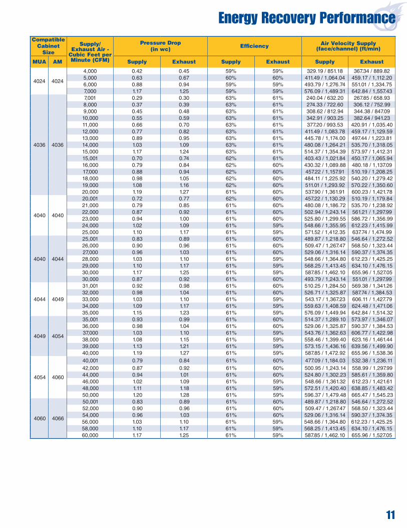
Energy Recovery PerformanceCompatible
Cabinet Size
Supply/ Exhaust Air -
Cubic Feet per Minute (CFM)
Pressure Drop (in wc) Efficiency Air Velocity Supply
(face/channel) (ft/min)
MUA AM Supply Exhaust Supply Exhaust Supply Exhaust
4024 4024
4,000 0.42 0.45 59% 59% 329.19 / 851.18 367.34 / 889.825,000 0.63 0.67 60% 60% 411.49 / 1,064.04 459.17 / 1,112.206,000 0.88 0.94 59% 59% 493.79 / 1,276.74 551.01 / 1,334.757,000 1.17 1.25 59% 59% 576.09 / 1,489.31 642.84 / 1,557.43
4036 4036
7,001 0.29 0.30 63% 61% 240.04 / 632.20 267.85 / 658.938,000 0.37 0.39 63% 61% 274.33 / 722.60 306.12 / 752.999,000 0.45 0.48 63% 61% 308.62 / 812.94 344.38 / 847.0910,000 0.55 0.59 63% 61% 342.91 / 903.25 382.64 / 941.2311,000 0.66 0.70 63% 61% 377.20 / 993.53 420.91 / 1,035.4012,000 0.77 0.82 63% 61% 411.49 / 1,083.78 459.17 / 1,129.5913,000 0.89 0.95 63% 61% 445.78 / 1,174.00 497.44 / 1,223.8114,000 1.03 1.09 63% 61% 480.08 / 1,264.21 535.70 / 1,318.0515,000 1.17 1.24 63% 61% 514.37 / 1,354.39 573.97 / 1,412.3115,001 0.70 0.74 62% 61% 403.43 / 1,021.84 450.17 / 1,065.9416,000 0.79 0.84 62% 60% 430.32 / 1,089.88 480.18 / 1,137.0917,000 0.88 0.94 62% 60% 457.22 / 1,157.91 510.19 / 1,208.2518,000 0.98 1.05 62% 60% 484.11 / 1,225.92 540.20 / 1,279.4219,000 1.08 1.16 62% 60% 511.01 / 1,293.92 570.22 / 1,350.6020,000 1.19 1.27 61% 60% 537.90 / 1,361.91 600.23 / 1,421.78
4040 4040
20,001 0.72 0.77 62% 60% 457.22 / 1,130.29 510.19 / 1,179.8421,000 0.79 0.85 61% 60% 480.08 / 1,186.72 535.70 / 1,238.9222,000 0.87 0.92 61% 60% 502.94 / 1,243.14 561.21 / 1,297.9923,000 0.94 1.00 61% 60% 525.80 / 1,299.55 586.72 / 1,356.9924,000 1.02 1.09 61% 59% 548.66 / 1,355.95 612.23 / 1,415.9925,000 1.10 1.17 61% 59% 571.52 / 1,412.35 637.74 / 1,474.99
4040 4044
25,001 0.83 0.89 61% 60% 489.87 / 1,218.80 546.64 / 1,272.5226,000 0.90 0.96 61% 60% 509.47 / 1,267.47 568.50 / 1,323.4427,000 0.96 1.03 61% 60% 529.06 / 1,316.14 590.37 / 1,374.3528,000 1.03 1.10 61% 59% 548.66 / 1,364.80 612.23 / 1,425.2529,000 1.10 1.17 61% 59% 568.25 / 1,413.45 634.10 / 1,476.1530,000 1.17 1.25 61% 59% 587.85 / 1,462.10 655.96 / 1,527.0530,000 0.87 0.92 61% 60% 493.79 / 1,243.14 551.01 / 1,297.99
4044 4049
31,001 0.92 0.98 61% 60% 510.25 / 1,284.50 569.38 / 1,341.2632,000 0.98 1.04 61% 60% 526.71 / 1,325.87 587.74 / 1,384.5333,000 1.03 1.10 61% 59% 543.17 / 1,367.23 606.11 / 1,427.7934,000 1.09 1.17 61% 59% 559.63 / 1,408.59 624.48 / 1,471.0635,000 1.15 1.23 61% 59% 576.09 / 1,449.94 642.84 / 1,514.32
4049 4054
35,001 0.93 0.99 61% 60% 514.37 / 1,289.10 573.97 / 1,346.0736,000 0.98 1.04 61% 60% 529.06 / 1,325.87 590.37 / 1,384.5337,000 1.03 1.10 61% 59% 543.76 / 1,362.63 606.77 / 1,422.9838,000 1.08 1.15 61% 59% 558.46 / 1,399.40 623.16 / 1,461.4439,000 1.13 1.21 61% 59% 573.15 / 1,436.16 639.56 / 1,499.9040,000 1.19 1.27 61% 59% 587.85 / 1,472.92 655.96 / 1,538.36
4054 4060
40,001 0.79 0.84 61% 60% 477.09 / 1,184.03 532.38 / 1,236.1142,000 0.87 0.92 61% 60% 500.95 / 1,243.14 558.99 / 1,297.9944,000 0.94 1.01 61% 60% 524.80 / 1,302.23 585.61 / 1,359.8046,000 1.02 1.09 61% 59% 548.66 / 1,361.32 612.23 / 1,421.6148,000 1.11 1.18 61% 59% 572.51 / 1,420.40 638.85 / 1,483.4250,000 1.20 1.28 61% 59% 596.37 / 1,479.48 665.47 / 1,545.23
4060 4066
50,001 0.83 0.89 61% 60% 489.87 / 1,218.80 546.64 / 1,272.5252,000 0.90 0.96 61% 60% 509.47 / 1,267.47 568.50 / 1,323.4454,000 0.96 1.03 61% 60% 529.06 / 1,316.14 590.37 / 1,374.3556,000 1.03 1.10 61% 59% 548.66 / 1,364.80 612.23 / 1,425.2558,000 1.10 1.17 61% 59% 568.25 / 1,413.45 634.10 / 1,476.1560,000 1.17 1.25 61% 59% 587.85 / 1,462.10 655.96 / 1,527.05

OAB
FBD
UD
LD/RDQ
S
ELECTRICALCONNECTION
GAS CONNECTIONBR
CE
V LR
N
RR
T
H & (H1)
G
VY
X
Z
A
OA
RD
BD/UD BR BRA M
K
K
J LD E
C
N T
R
CE R
FJ
N1
R1
S
P1RR/LR
P
LD
BR
FJ
AD1AD2
AD1AD2
PLAN VIEW
RIGHT SIDE VIEW
FAN SECTION BURNER SECTION
COIL SECTION(OPTIONAL)
EVAPORATIVECOOLER
(OPTIONAL)
ENERGYRECOVERYSECTION
(OPTIONAL)
FILTER SECTION
(OPTIONAL)FILTER MIX BOX
(OPTIONAL)ORINLET PLENUM
(OPTIONAL)INLET HOOD(OPTIONAL)OR
See page 10 for energy recovery dimensions
See page 7 for evaporative cooler dimensions
See page 8/9 for coil section dimensions
BB
R
R
P
4000 AM Horizontal Model
12
Dimensions
Mo
de
l
Air Handler
Ba
se F
ram
eF
orm
ed
Ch
an
ne
lB
ase
Fra
me
S
tru
ctu
ral
An
gle
Fil
ter
Se
cti
on
Wid
th
Fil
ter
Mix
bo
x L
en
gth
Filte
r M
ixb
ox
L
en
gth
Wit
h S
ide
Re
turn
Dis
ch
arg
e L
en
gth
Dis
ch
arg
e W
idth
Re
turn
Air
Le
ng
th
Re
turn
Air
Le
ng
th
Re
turn
Air
Wid
th
Re
turn
Air
He
igh
t
Dis
ch
arg
e H
eig
ht
Filte
r S
ec
tio
n L
en
gth
Ple
nu
m W
idth
Ple
nu
m L
en
gth
Inle
t H
oo
d L
en
gth
Min
imu
m L
eg
He
igh
t
Ple
nu
m H
eig
ht
Wid
th
He
igh
t
Le
ng
th
A B C D E F G H H1 J K L M N N1 P P1 Q R R1 S T V X Y Z AA BB
4024 40 40 109 - 4 - 62 62 62 4 5.5 20 29 18 27 32 22 34 4 2 3 10 30 40 60 48 36 40
4036 58 58 120 - 4 - 62 66 77 5 5.5 25 47 26 41 50 32 50 4 2 3 4 30 63 77 72 36 63
4040 63 63 130 - 4 - 81 68 77 6 6.5 33 50 30 41 55 40 53 4 2 3 4 30 63 77 84 36 63
4044 69 69 137 - 4 - 81 70 79 6 6.5 36 56 32 43 61 46 59 4 2 3 4 30 76 84 84 36 76
4049 76 76 140 - 4 - 81 72 80 6 6.5 39 63 34 44 68 53 66 4 2 3 4 30 76 84 84 36 76
4054 85 85 144 86 58 6 - 100 77 90 6 6.5 43 72 39 55 77 55 75 4 2 3 4 30 94 77 96 48 94
4060 94 94 154 90 64 6 - 100 77 85 6 6.5 48 81 38 50 86 65 84 4 2 3 4 30 94 77 96 48 94
4066 104 96 158 94 64 6 - 119 84 100 6 6.5 50 91 45 65 96 67 90 4 2 3 4 30 112 120 96 48 96
4073 112 96 163 94 69 - 3 119 84 107 6 6.5 50 99 44 72 104 64 90 4 2 3 4 30 112 120 96 48 96
4080 131 112 171 75 96 - 4 139 94 112 6 7.5 60 116 48 77 123 76 106 4 2 3 4 30 131 138 96 48 112
4089 131 112 177 81 96 - 4 139 94 112 6 7.5 60 116 48 77 123 76 106 4 2 3 4 30 131 138 96 48 112

4000 AM Upright Model
BF
Q
BD RD/LD
BRCE
FJ
S
A
MK K J
LD L
D
C
E
N
TRPR
CE
BR
BD/UD
G
BR
V
V
HN
T
R P R
OAOA
BR
ELECTRICALCONNECTION
GASCONNECTION
UD RD
AA
FJAD2
AD1
FAN
SECT
ION
BURN
ER S
ECTI
ONSE
RVIC
E PL
ATFO
RM(O
PTIO
NAL)
FILT
ER
SECT
ION
(OPT
IONA
L)
FILT
ER M
IX B
OX(O
PTIO
NAL)
ORLE
GS(O
PTIO
NAL)
RAIN
SKI
RT(S
TAND
ARD
FOR
OUTD
OOR
EQUI
PMEN
T)
FRONT VIEWRIGHT SIDE VIEW
AD2
AD1
13
LEGENDOA = Outside Air
CE = Control Enclosure
BD = Bottom Discharge
LD = Left Discharge
RD = Right Discharge
UD = Up Discharge
BR = Bottom Return
RR = Right Return
LR = Left Return
FJ = Field Joint (Models 4054 - 4089)
AD1 = Access Door (Models 4080 & 4089)
AD2 = Access Door (Models 4024 - 4073)
• All dimensions are in inches.• All weights are in pounds.• All dimensions and weights are subject to change without notice.• Dimensions apply to both horizontal and upright units.• Filters are shipped loose. • Legs are shipped loose.• Control enclosure for 3" or smaller manifolds is 57" H x 57" W x 25" D. (B dimension of Model 4024 cabinet size is approximately 20" smaller than the control enclosure. Model 4049 control enclosure is 57" H x 57" W x 20" D.)• To minimize the potential for water entrainment, an inlet hood with moisture limiter ir inlet plenum may be desirable.• Outdoor air duct size varies. Consult Rapid Engineering LLC.• Control enclosure can be located on left or right side of unit. (Shown on right side in drawings)
IMPORTANT NOTES:
Model
Estimated Shipping Weights
HorizontalFan
Section
HorizontalBurner Section
Horizontal ServicePlatforms Filter
SectionFilter
MixboxInlet Hood
Inlet Plenum
UprightServicePlatform
UprightFan
Section
UprightBurner SectionBasic With
OA* AddWith
FMB** Add
4024 1,254 475 70 190 320 611 80 343 340 1,289
4036 2,110 520 70 205 465 843 135 657 430 2,129
4040 2,427 606 69 209 525 1,012 210 661 470 2,443
4044 2,783 630 70 215 600 1,122 226 866 500 2,816
4049 3,114 650 68 230 640 1,230 248 870 525 3,150
4054 2,383 1,671 675 66 235 685 1,597 370 1,150 580 2,373 1,754
4060 2,673 1,936 710 70 240 760 1,707 395 1,157 600 2,663 2.029
4066 2,961 2,126 735 65 275 875 2,084 410 1,635 620 3,129 2,228
4073 4,219 2,332 760 65 275 1,125 2,220 425 2,052 630 4,553 2,541
4080 3,667 4,790 805 70 310 1,400 2,776 590 2,128 720 4,002 4,924
4089 4,101 4,849 820 70 310 1,400 2,776 590 2,128 720 4,503 4,983
* Outside Air ** Filter Mix Box

C
D E
A M
K
K
J L
FJ G
R Y
X A
Z
GAS CONNECTIONF
B N
H
ELECTRICALCONNECTION
BD/UD
UD
BD
RD
LD/RD
LD
CE
CE
OA
OA
FJ
AD1AD2
AD1AD2
FAN SECTION BURNER SECTION COIL SECTION(OPTIONAL)
EVAPORATIVECOOLER
(OPTIONAL)
FILTERSECTION
(OPTIONAL)
INLET PLENUM(OPTIONAL)
INLET HOOD(OPTIONAL)OR
RIGHT SIDE VIEW
PLAN VIEW
ENERGYRECOVERYSECTION
(OPTIONAL)
BB
See page 10 for energy recovery dimensions
See page 7 for evaporative cooler dimensions
See page 8/9 for coil section dimensions
4000 MUA Horizontal Model
14
Dimensions
Mo
de
l
Air Handler
Ba
se F
ram
e
Fo
rme
d C
ha
nn
el
Bas
e Fr
ame
Stru
ctur
al A
ngle
Filt
er S
ecti
on W
idth
Dis
ch
arg
e L
en
gth
Dis
ch
arg
e W
idth
Dis
ch
arg
e H
eig
ht
Min
imu
m L
eg
H
eig
ht
Filte
r S
ec
tio
n
Le
ng
th
Ple
nu
m W
idth
Ple
nu
m L
en
gth
Inle
t H
oo
d L
en
gth
Ple
nu
m H
eig
ht
Wid
th
He
igh
t
Le
ng
th
A B C D E F G H J K L M N P R X Y Z BB
4024 40 40 109 - 4 - 62 3 4 5.5 20 29 34 36 30 52 60 48 40
4036 58 58 120 - 4 - 62 3 5 5.5 25 47 50 36 30 63 77 72 63
4040 63 63 130 - 4 - 81 3 6 6.5 33 50 53 36 30 76 84 84 63
4044 69 69 137 - 4 - 81 3 6 6.5 36 56 59 36 30 76 84 84 76
4049 76 76 140 - 4 - 81 3 6 6.5 39 63 66 36 30 94 77 84 76
4054 85 85 144 86 58 6 - 100 3 6 6.5 43 72 75 48 30 94 77 96 94
4060 94 94 154 90 64 6 - 100 3 6 6.5 48 81 84 48 30 112 120 96 94
4066 104 96 158 94 64 6 - 119 3 6 6.5 50 91 90 48 30 112 120 96 96
4073 112 96 163 94 69 - 3 119 3 6 6.5 50 99 90 48 30 131 138 96 96
4080 131 112 162 75 87 - 4 139 3 6 7.5 60 116 106 48 30 131 138 96 112
4089 131 112 168 81 87 - 4 139 3 6 7.5 60 116 106 48 30 131 138 96 112
Mo
de
l
Estimated Shipping Weights
Ho
rizo
nta
lF
an
Se
cti
on
Ho
rizo
nta
lB
urn
er
Se
cti
on
Filte
r S
ec
tio
n
Inle
t H
oo
d
Inle
t P
len
um
4024 1,325 320 80 452
4036 2,110 465 135 657
4040 2,530 525 210 862
4044 2,783 600 226 866
4049 3,305 640 248 1,126
4054 2,518 1,695 685 370 1,150
4060 2,808 1,973 760 395 1,627
4066 3,036 2,159 875 410 1,635
4073 4,525 2,361 1,125 425 2,052
4080 3,667 4,790 1,400 590 2,128
4089 4,101 5,210 1,400 590 2,128

15
F B
N H
GASCONNECTION
R
G
K M
A
K J
L
D
C
E
ELECTRICALCONNECTION
OA
BD/UD
CE
OA
CE
UDBD RDRD/LD LD
P
FJ
AD1
AD2
FRONT VIEWRIGHT SIDE VIEW
FAN
SECT
ION
BURN
ER S
ECTI
ONFI
LTER
SECT
ION
(OPT
IONA
L)
LEGS
(OPT
IONA
L)
RAIN
SKI
RT(S
TAND
ARD
FOR
OUTD
OOR
EQUI
PMEN
T)
FJAD2
AD1
4000 MUA Upright Model
IMPORTANT NOTES:• All dimensions are in inches.• All weights are in pounds.• All dimensions and weights are subject to change without notice.• Dimensions apply to both horizontal and upright units.• Filters are shipped loose. • Legs are shipped loose.• Control enclosure for 3" or smaller manifolds is 57" H x 57" W x 25" D. (B dimension of Model 4024 cabinet size is approximately 20" smaller than the control enclosure. Model 4049 control enclosure is 57" H x 57" W x 20" D.)• To minimize the potential for water entrainment, an inlet hood with moisture limiter or inlet plenum may be desirable.• Outdoor air duct size varies. Consult Rapid Engineering LLC.• Control enclosure can be located on left or right side of unit. (Shown on right side in drawings)
Model
EstimatedShipping Weights
Upright Fan
Section
Upright Burner Section
4024 1,360
4036 2,129
4040 2,546
4044 2,816
4049 3,341
4054 2,508 1,760
4060 2,798 2,076
4066 3,204 2,234
4073 4,859 2,441
4080 4,002 4,624
4089 4,503 5,044
LEGEND
OA = Outside Air
CE = Control Enclosure
BD = Bottom Discharge
LD = Left Discharge
RD = Right Discharge
UD = Up Discharge
FJ = Field Joint (Models 4054 - 4089)
AD1 = Access Door (Models 4080 & 4089)
AD2 = Access Door (Models 4024 - 4073)

4000 FR Horizontal Model
B Q
Z
UD
F
BD
LD/RD
80% (Optional)
GAS CONNECTION
80%(Optional)
W
OA
A OA
XTS
R
BR P
RCE
FJ
E
C
D
LJ
K
MA
K
RD
BD/UD
CE
FJ
ELECTRICALCONNECTION
LD
AD1AD2
AD1AD2
PLAN VIEW
RIGHT SIDEVIEW
ER
BR
FAN SECTION BURNER SECTIONINLET HOOD(OPTIONAL)
16
Dimensions
Mo
de
l
Air Handler
Ba
se F
ram
e F
orm
ed
C
ha
nn
el
Ba
se F
ram
e S
tru
ctu
ral
An
gle
Ou
tsid
e A
ir L
en
gth
Filte
r S
tan
d H
eig
ht
Dis
ch
arg
e L
en
gth
Dis
ch
arg
e W
idth
Dis
ch
arg
e L
en
gth
Re
turn
Air
Wid
th
Dis
ch
arg
e H
eig
ht
Re
turn
Air
Le
ng
th
Lo
uve
r H
eig
ht
Inle
t H
oo
d / D
uc
t H
eig
ht
Inle
t H
oo
d L
en
gth
Min
imu
m L
eg
He
igh
t
Wid
th
H
eig
ht
Le
ng
th
A B C D E F G H J K L M N P Q R S T U W X Y Z
4024 40 40 109 - 4 - 10 24 4 5.5 20 29 30 32 34 4 18 10 28 21 27 36 3
4036 58 58 120 - 4 - 12 36 5 5.5 25 47 30 50 50 4 26 4 34 30 35 36 3
4040 63 63 130 - 4 - 12 36 6 6.5 33 50 30 55 53 4 30 4 34 32.5 37 36 3
4044 69 69 137 - 4 - 16 36 6 6.5 36 56 30 61 59 4 32 4 45 35.5 39 36 3
4049 76 76 140 - 4 - 16 36 6 6.5 39 63 30 68 66 4 34 4 45 39 42 36 3
4054 85 85 144 86 58 6 - 16 36 6 6.5 43 72 30 77 75 4 39 4 45 43.5 46 48 3
4060 94 94 154 90 64 6 - 20 36 6 6.5 48 81 30 86 84 4 38 4 56 48 50 48 3
4066 104 96 158 94 64 6 - 20 48 6 6.5 50 91 30 96 90 4 45 4 56 49 51 48 3
4073 112 96 163 94 69 - 3 24 60 6 6.5 50 99 30 104 90 4 44 4 68 49 51 48 3
4080 131 112 171 75 96 - 4 24 60 6 7.5 60 116 30 123 106 4 48 4 68 57 57 48 3
4089 131 112 177 81 96 - 4 24 60 6 7.5 60 116 30 123 106 4 48 4 68 57 57 48 3
N
A x
U
A x
U
N
A x W
A x W
X
FILTE
RS
Outdoor AirDuct Sleeve
Filtered InletHood
Louver Duct Louver
Mo
de
l
Estimated Shipping Weights
Ho
rizo
nta
l F
an
S
ec
tio
n
Ho
rizo
nta
l B
urn
er
S
ec
tio
n
Filte
r S
ec
tio
n
Inle
t H
oo
d
4024 1,245 320 80
4036 2,055 465 135
4040 2,354 525 210
4044 2,716 600 226
4049 3,034 640 248
4054 2,383 1,470 685 370
4060 2,673 1,712 760 395
4066 2,961 1,847 875 410
4073 4,219 1,994 1,125 425
4080 3,667 4,359 1,400 590
4089 4,101 4,418 1,400 590

4000 FR Upright Model
BF
ZQ
ELECTRICALCONNECTION
GASCONNECTION
T
S x P80% BR
(Optional)
80% ER(Optional)
20% OA(Optional)
20% OA
(Optional)
B
H
K
A
M
20% OA(Optional)
K M KT
G
E
C
D
L
JK
AD2
AD1
A
H
BD/UDBD LD
CE
UDRDRD/LD
CE
Y
FJ
FAN
SECT
ION
BURN
ER S
ECTI
ON
FILT
ER S
TAND
w
ith B
ULK
FILT
ERM
EDIA
(OPT
IONA
L)
LEGS
(OPT
IONA
L)
FRONT VIEWRIGHT SIDE VIEW
FJAD2
AD1
17
IMPORTANT NOTES:• All dimensions are in inches.• All weights are in pounds.• All dimensions and weights are subject to change without notice.• Dimensions apply to both horizontal and upright units.• Filters are shipped loose. • Legs are shipped loose.• Control enclosure for 3" or smaller manifolds is 57" H x 57" W x 25" D. (B dimension of Model 4024 cabinet size is approximately 20" smaller than the control enclosure. Model 4049 control enclosure is 57" H x 57" W x 20" D.)• To minimize the potential for water entrainment, an inlet hood with moisture limiter or inlet plenum may be desirable.• Outdoor air duct size varies. Consult Rapid Engineering LLC.• Control enclosure can be located on left or right side of unit. (Shown on right side in drawings)
LEGEND
OA = Outside Air
CE = Control Enclosure
BD = Bottom Discharge
LD = Left Discharge
RD = Right Discharge
UD = Up Discharge
BR = Bottom Return
ER = End Return
FJ = Field Joint (Models 4054 - 4089)
AD1 = Access Door (Models 4080 & 4089)
AD2 = Access Door (Models 4024 - 4073)
Model
EstimatedShipping Weights
Upright Fan
Section
Upright Burner Section
Filter Stand
4024 1,230 95
4036 2,054 140
4040 2,360 150
4044 2,704 160
4049 3,017 175
4054 2,373 1,553 320
4060 2,663 1,805 350
4066 3,129 1,949 400
4073 4,553 2,203 450
4080 4,002 4,493 500
4089 4,503 4,552 500

18
4000 VAV Horizontal Model
C
K
A M
KJ L
FJ
G
N
X
Y Z
GAS CONNECTION
F
B
20% to 100% AIR
ELECTRICAL CONNECTION
BD
CE
CE
BD
OA
OA
FJ
AD1AD2
AD1AD2
D E
A
FAN SECTION BURNER SECTION
COIL SECTION(OPTIONAL)
EVAPORATIVECOOLER
(OPTIONAL)
FILTERSECTION
(OPTIONAL)
INLET PLENUM(OPTIONAL)
INLET HOOD(OPTIONAL)OR
RIGHT SIDE VIEW
PLAN VIEW
ENERGYRECOVERYSECTION
(OPTIONAL)
See page 10 for energy recovery dimensions
See page 7 for evaporative cooler dimensions
See page 8/9 for coil section dimensions
BB
Dimensions
Mo
de
l
Air Handler
Ba
se F
ram
e F
orm
ed
C
ha
nn
el
Ba
se F
ram
e S
tru
ctu
ral
An
gle
Filte
r S
ec
tio
n W
idth
Min
imu
m L
eg
He
igh
t
Dis
ch
arg
e L
en
gth
Dis
ch
arg
e W
idth
Filte
r S
ec
tio
n L
en
gth
Ple
nu
m W
idth
Ple
nu
m L
en
gth
Inle
t H
oo
d L
en
gth
Ple
nu
m H
eig
ht
Wid
th
He
igh
t
Le
ng
th
A B C D E F G H J K L M N X Y Z BB
4024 40 59 109 - 4 - 62 36 4 5.5 24 29 30 40 60 48 40
4036 58 84 120 - 4 - 62 36 5 5.5 32 47 30 63 77 72 63
4040 63 94 130 - 4 - 81 36 6 6.5 35 50 30 63 77 84 63
4044 69 102 137 - 4 - 81 36 6 6.5 35 56 30 76 84 84 76
4049 76 109 140 - 4 - 81 36 6 6.5 40 63 30 76 84 84 76
4054 85 124 144 86 58 6 - 100 48 6 6.5 40 72 30 94 77 96 94
4060 94 138 154 90 64 6 - 100 48 6 6.5 43 81 30 94 77 96 94
4066 104 140 158 94 64 6 - 119 48 6 6.5 43 91 30 112 120 96 96
4073 112 137 163 94 69 - 3 119 48 6 6.5 43 99 30 112 120 96 96
4080 131 156 171 75 96 - 4 139 48 6 7.5 43 116 30 131 138 96 112
4089 131 156 177 81 96 - 4 139 48 6 7.5 43 116 30 131 138 96 112
Mo
de
l
Estimated Shipping Weights
Ho
rizo
nta
l F
an
S
ec
tio
n
Ho
rizo
nta
lB
urn
er
Se
cti
on
Filte
r S
ec
tio
n
Inle
t H
oo
d
Inle
t P
len
um
4024 1,564 320 80 343
4036 2,585 465 135 657
4040 2,982 525 210 661
4044 3,413 600 226 866
4049 3,804 640 248 870
4054 2,953 2,061 685 370 1,150
4060 3,333 2,396 760 395 1,157
4066 3,711 2,626 875 410 1,635
4073 4,959 2,842 1,125 425 2,052
4080 4,537 5,640 1,400 590 2,128
4089 4,971 5,699 1,400 590 2,128

19
F B
ELECTRICALCONNECTION
GASCONNECTION
G
N
E
C
D
L
J K M K
A
OA
BD
OA
CECE
BD
H
FJAD2
AD1
FRONT VIEWRIGHT SIDE VIEW
FAN
SECT
ION
BURN
ER S
ECTI
ONFI
LTER
SECT
ION
(OPT
IONA
L)
LEGS
(OPT
IONA
L)
RAIN
SKI
RT(S
TAND
ARD
FOR
OUTD
OOR
EQUI
PMEN
T)
FJAD2
AD1
20% to 100% Air
4000 VAV Upright Model
IMPORTANT NOTES:• All dimensions are in inches.• All weights are in pounds.• All dimensions and weights are subject to change without notice.• Dimensions apply to both horizontal and upright units.• Filters are shipped loose. • Legs are shipped loose. Models 4024-4049 require four legs. Models 4054-4089 require six legs.• Control enclosure for 3" or smaller manifolds is 57" H x 57" W x 25" D. (B dimension of Model 4024 cabinet size is approximately 20" smaller than the control enclosure. Model 4049 control enclosure is 57" H x 57" W x 20" D.)• To minimize the potential for water entrainment, an inlet hood with moisture limiter or inlet plenum may be desirable.• Outdoor air duct size varies. Consult Rapid Engineering LLC.• Control enclosure can be located on left or right side of unit. (Shown on right side in drawings)
LEGENDOA = Outside Air
CE = Control Enclosure
BD = Bottom Discharge
FJ = Field Joint (Models 4054 - 4089)
AD1 = Access Door (Models 4080 & 4089)
AD2 = Access Door (Models 4024 - 4073)
Model
EstimatedShipping Weights
Upright Fan
Section
Upright Burner Section
4024 1,589
4036 2,627
4040 3,033
4044 3,470
4049 3,870
4054 2,943 2,144
4060 3,323 2,489
4066 3,879 2,278
4073 5,293 3,051
4080 4,872 5,774
4089 5,373 5,833

20
One-Way Discharge Head
IMPORTANT NOTES:• All dimensions are in inches.• All weights are in pounds.• All dimensions and weights are subject to change without notice.• The discharge head has manually adjustable horizontal blades (vertical blades are optional). • Discharge head requires field support and mounting by installer.• Dimensions C2 (Discharge Inside 2), H and J only applicable to VAV units.
END VIEW RIGHT SIDE VIEW
Dimensions
WeightModel A C1 C2 D E F G H J
Dischage Inside
1 2
4024 40 24.3 28.3 33.3 2 40 3.5 19 38 20 x 29 24 x 29 75
4036 58 29.3 36.3 51.3 3 58 3.5 26 56 25 x 47 32 x 47 105
4040 63 37.3 39.3 54.3 4 63 4.5 31 61 33 x 50 35 x 50 140
4044 69 40.3 39.3 60.3 4 69 4.5 33 67 36 x 56 35 x 56 180
4049 76 43.3 44.3 67.3 4 76 4.5 33 74 39 x 63 40 x 63 190
4054 85 47.3 44.3 76.3 4 85 4.5 39 83 43 x 72 40 x 72 210
4060 94 52.3 47.3 85.3 4 94 4.5 44 92 48 x 81 43 x 81 250
4066 104 54.3 47.3 95.3 4 96 4.5 44 102 50 x 91 43 x 91 290
4073 112 54.3 47.3 103.3 4 96 4.5 41 110 50 x 99 43 x 99 380
4080 131 64.3 47.3 120.3 4 112 5.5 44 129 60 x 116 43 x 116 480
4089 131 64.3 47.3 120.3 4 112 5.5 44 129 60 x 116 43 x 116 480
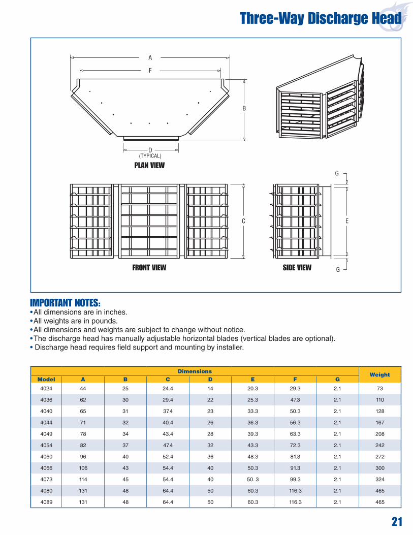
Three-Way Discharge Head
F
D(TYPICAL)
B
A
C E
G
G
PLAN VIEW
FRONT VIEW SIDE VIEW
IMPORTANT NOTES:• All dimensions are in inches.• All weights are in pounds.• All dimensions and weights are subject to change without notice.• The discharge head has manually adjustable horizontal blades (vertical blades are optional). • Discharge head requires field support and mounting by installer.
Dimensions WeightModel A B C D E F G
4024 44 25 24.4 14 20.3 29.3 2.1 73
4036 62 30 29.4 22 25.3 47.3 2.1 110
4040 65 31 37.4 23 33.3 50.3 2.1 128
4044 71 32 40.4 26 36.3 56.3 2.1 167
4049 78 34 43.4 28 39.3 63.3 2.1 208
4054 82 37 47.4 32 43.3 72.3 2.1 242
4060 96 40 52.4 36 48.3 81.3 2.1 272
4066 106 43 54.4 40 50.3 91.3 2.1 300
4073 114 45 54.4 40 50. 3 99.3 2.1 324
4080 131 48 64.4 50 60.3 116.3 2.1 465
4089 131 48 64.4 50 60.3 116.3 2.1 465
21

22
RIGHT SIDE VIEWEND VIEW
Four-Way Discharge Head
IMPORTANT NOTES:• All dimensions are in inches.• All weights are in pounds.• All dimensions and weights are subject to change without notice.• The discharge head has manually adjustable horizontal blades (vertical blades are optional). • Discharge head requires field support and mounting by installer.• Dimensions D2 (Inside Dimension of Duct Connections 2), F and G only applicable to VAV units.
Dimensions
WeightModel A B C D1 D2 E F G
Inside Dimensions of Duct
Connections
1 2
4024 40 40 46 24.3 28.3 33.3 19 38 20 x 29 24 x 29 220
4036 58 58 46 29.3 36.3 51.3 26 56 25 x 47 32 x 47 320
4040 63 63 46 37.3 39.3 54.3 31 61 33 x 50 35 x 50 380
4044 69 69 46 40.3 39.3 60.3 33 67 36 x 56 35 x 56 410
4049 76 76 46 43.3 44.3 67.3 33 74 39 x 63 40 x 63 440
4054 85 85 58 47.3 44.3 76.3 39 83 43 x 72 40 x 72 620
4060 94 94 58 52.3 47.3 85.3 44 92 48 x 81 43 x 81 670
4066 96 104 58 54.3 47.3 95.3 44 102 50 x 91 43 x 91 680
4073 96 112 58 54.3 47.3 103.3 41 110 50 x 99 43 x 99 780
4080 112 131 58 64.3 47.3 120.3 44 129 60 x 116 43 x 116 1,090
4089 112 131 58 64.3 47.3 120.3 44 129 60 x 116 43 x 116 1,090

Discharge Plate
IMPORTANT NOTES:• All dimensions are in inches.• All weights are in pounds.• All dimensions and weights are subject to change without notice. • Discharge plate requires field support and mounting by installer.
DimensionsWeight
Model A B C D E (min.) E (max.)
4024 42 54 3 - 25 38 80
4036 47 72 3 - 36 54 110
4040 55 75 3 - 42 64 130
4044 58 81 3 - 46 70 140
4049 61 88 3 - 50 75 160
4054 65 97 3 - 56 84 180
4060 70 106 3 53 64 96 230
4066 72 116 3 58 70 105 250
4073 72 124 3 62 75 112 260
4080 82 140 4 70 88 132 330
4089 82 140 4 70 88 132 330
DISCHARGE PLATE
SUPPORT RODS(BY OTHERS)
FAN SECTION
CENTER HOLESON 4060 THRU 4089
13/16” HOLES
1¾” TYPICAL4 CORNERS
2”
2”TYPICAL
D
BD
A
C
E
RIGHT SIDE VIEW
23

Legs
BOLT TWO CORNER LEGS TOGETHER TO MAKE AN INTERMEDIATE
BOTTOM PLATE BOLTS TOOUTSIDE OF LEG
INTERMEDIATE LEG
CORNER LEG
NOTE
IMPORTANT NOTES:• All dimensions are in inches.• All weights are in pounds.• All dimensions and weights are subject to change without notice.• Models 4024 - 4049 upright air handlers with 84" or 96" legs, angle bracing is provided.*For models 4036-4049 upright air handlers, 24" legs are not available. For models 4054-4089, 24" and 36" legs are not available.
Leg HeightWeight (each leg)
Corner Intermediate
24 34 74
36 43 92
48 52 108
60 75 156
72 88 182
84 100 206
96 144 294
24
Orientation Horizontal UprightStyle AM FR MUA VAV AM
AM FR MUA VAV VAV with Filter Section VAV without Filter Section
TypeFilter Section MixboxModel
4024
Four Corner LegsFour Corner
& Two Intermediate
Four Corner Legs
N/A N/A4036
Four Corner Legs*
4040404440494054
Four Corner & Two IntermediateFour Corner
& Four Intermediate
Six Corner Legs Six Corner legs
40604066407340804089

Inlet Hoods
IMPORTANT NOTES:• All dimensions are in inches.• All weights are in pounds.• All dimensions and weights are subject to change without notice.
DimensionsWeight
Model A B C
4024 40 21 27 53
4036 58 30 35 144
4040 63 32.5 37 182
4044 69 35.5 39 200
4049 76 39 42 220
4054 85 43.5 46.5 280
4060 94 48 50 310
4066 104 49 51 325
4073 112 49 51 335
4080 / 4089 131 57 57 390
25
AIR HANDLER
FLASHING TAPE
INLETB
A
C
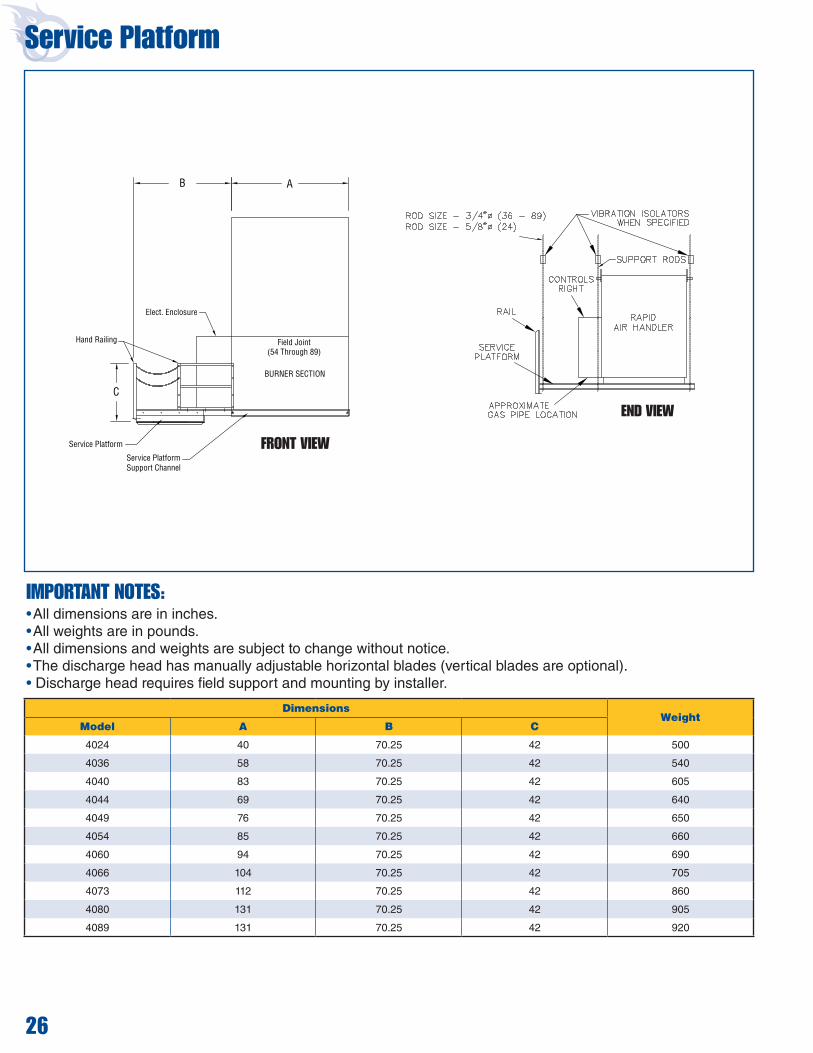
Service Platform
FRONT VIEW
B
C
Hand Railing
Elect. Enclosure
Field Joint(54 Through 89)
BURNER SECTION
Service Platform
Service PlatformSupport Channel
A
IMPORTANT NOTES:• All dimensions are in inches.• All weights are in pounds.• All dimensions and weights are subject to change without notice.• The discharge head has manually adjustable horizontal blades (vertical blades are optional). • Discharge head requires field support and mounting by installer.
END VIEW
26
DimensionsWeight
Model A B C
4024 40 70.25 42 500
4036 58 70.25 42 540
4040 83 70.25 42 605
4044 69 70.25 42 640
4049 76 70.25 42 650
4054 85 70.25 42 660
4060 94 70.25 42 690
4066 104 70.25 42 705
4073 112 70.25 42 860
4080 131 70.25 42 905
4089 131 70.25 42 920
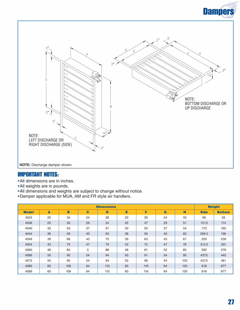
Dampers
27
NOTE:BOTTOM DISCHARGE ORUP DISCHARGE
NOTE:LEFT DISCHARGE ORRIGHT DISCHARGE (SIDE)
IMPORTANT NOTES:• All dimensions are in inches.• All weights are in pounds.• All dimensions and weights are subject to change without notice.• Damper applicable for MUA, AM and FR style air handlers.
Dimensions Weight
Model A B C D E F G H Side Bottom
4024 20 34 24 38 20 29 24 33 66 56
4036 25 50 29 54 25 47 29 51 121.5 114
4040 33 53 37 57 33 50 37 54 170 160
4044 36 59 40 63 36 56 40 60 206.5 196
4049 39 66 43 70 39 63 43 67 250 239
4054 43 75 47 79 43 72 47 76 313.5 301
4060 48 84 5 88 48 81 52 85 392 378
4066 50 90 54 94 50 91 54 95 437.5 442
4073 50 90 54 94 50 99 54 103 437.5 481
4080 60 106 64 110 60 116 64 120 618 677
4089 60 106 64 110 60 116 64 120 618 677
NOTE: Discharge damper shown.

Roof Curbs
28
BURNER SECTION
FAN SECTION
FAN & BURNER SECTION
INLET END
INLET END
Caulk required for outside perimeterof roof curb at bolted joints.
1 1/2 FLG. Mounting Surface
NOTE:End piece isflush with side.Inlet and dischargeend panel.
Side Panel
A*C B*
Models 4024-4054
Models 4040 through 4054
Models 4060-4089A*C
B*D
E
3 TYP.
1 TYP12
3 FLG.
IMPORTANT NOTES:• All dimensions are in inches.• All weights are in pounds.• All dimensions and weights are subject to change without notice.
Dimensions
WeightModel A
BC D
E
AM/FR/VAV MUA AM/FR/VAV MUA
4024 38 108 108 34.8125 - - - 187.27
4036 56 119 119 52.8125 - - - 230.93
4040 61 129 129 57.8125 - - - 251.03
4044 67 136 136 63.8125 - - - 269.41
4049 74 139 139 70.8125 - - - 284.92
4054 83 143 143 79.8125 - - - 305.03
4060 92 153 153 88.8125 57 96 96 330.88
4066 102 157 157 98.8125 61 96 96 352.71
4073 109 161 161 105.8125 65 96 96 370.52
4080 128 169 160 124.8125 73 96 87 412.45
4089 128 175 166 124.8125 79 96 87 419.34

Roof Curb Duct Adapter
29
IMPORTANT NOTES:• All dimensions are in inches.• All weights are in pounds.• All dimensions and weights are subject to change without notice.• Dimensions shown for fan/burner section only.• Roof curb is shipped knocked down.
Dimensions Weight
Model AB
C DE
AM/FR/VAV MUAAM/FR/VAV MUA AM/FR/VAV MUA
4024 38 108 108 34.8125 - - - 207 198
4036 56 119 119 52.8125 - - - 255 245
4040 61 129 129 57.8125 - - - 279 268
4044 67 136 136 63.8125 - - - 300 288
4049 74 139 139 70.8125 - - - 318 305
4054 83 143 143 79.8125 - - - 351 333
4060 92 153 153 88.8125 58 95 95 382 361
4066 102 157 157 98.8125 52 95 95 408 386
4073 109 161 161 105.8125 66 95 95 428 404
4080 128 169 160 124.8125 75 95 85 480 452
4089 128 175 166 124.8125 81 95 85 487 459
- - - -
- - - -
- - - -
CAULK REQUIRED FOR OUTSIDE PERIMETEROF ROOF CURB AT
BOLTED JOINTS.NOTE:END PIECE IS FLUSH WITH SIDE.
1 1/2 FLG. MOUNTING SURFACE
SIDE PANEL INLET AND DISCHARGE END PANEL.
3 FLG.
B *
A *C
B *
D
19 TYP .
A *
E1 1
2 TYP.
C
19 TYP
3 TYP.
INLET END
INLET END
OPTIONAL DUCTADAPTER SLEEVE
CAULK REQUIRED FOROUTSIDE PERIMETEROF ROOF CURB AT
BOLTED JOINTS.
MODELS 4073THRU 4089 ONLY.
MODEL 4089 ONLY
MODELS 4040THRU 4054
CAULK REQUIRED FOROUTSIDE PERIMETEROF ROOF CURB AT
BOLTED JOINTS.
DETAIL 3CORNER CONNECTION
7 BOLTS, FLAT WASHERS,FLANGE NUTS.
DETAIL 2SPLICE & CROSS BRACE
20 BOLTS, FLAT WASHERS,FLANGE NUTS.
THESE TWO EDGE MUST BE INSTALLEDFLUSH TO MAINTAIN THE PROPER ODDIMENSION OF TOP MOUNTINGSURFACES.

Printed in U.S.A. RP4DSGNA 1216 Rev E
Thank You for Your Business!
This product is not for residential use.This document is intended to assist licensed professionals in the exercise of their professional judgment.
Rapid Engineering LLC1100 Seven Mile Road NWComstock Park, MI 49321Telephone: +1.616.784.0500Toll Free: 800.536.3461Fax: +1.616.784.0435www.rapidengineering.com© 2016 Rapid Engineering LLC All rights reserved. No part of this work covered by the copyrights herein may be reproduced or copied in any form or by any means – graphic, electronic, or mechanical, including photocopying, recording, taping, or information storage and retrieval systems – without written permission of Rapid Engineering LLC.