AIR HANDLERS TA
32
AIR HANDLERS TA T-CLASS™ SPLIT SYSTEM UNITS UPFLOW/HORIZONTAL - R-410A - 50 HZ Bulletin No. 490133 December 2010 Supersedes August 2009 ENGINEERING DATA Nominal Capacity - 21.1 to 70 kW Optional Electric Heat - 7.6 to 25.5 kW MODEL NUMBER IDENTIFICATION T A A 120 S 4 D - 1 M Major Design Sequence A = 1st Generation B = 2nd Generation Unit Type A = Split System Air Handler Brand/Family T = T-Class™ Product Line Cooling Efficiency S = Standard Efficiency Minor Design Sequence 1 = 1st Revision 2 = 2nd Revision 3 = 3rd Revision Voltage M = 380/420V-3 phase-50hz Nominal Cooling Capacity - kW 072 = 21.1 kW 090 = 26.4 kW 120 = 35.2 kW 150 = 44.0 kW 180 = 53 kW 240 = 70 kW Refrigerant Type 4 = R-410A Refrigerant Circuits S = Single Circuit D = Dual Circuits 180-240 Models 072-090-120-150 Models
Transcript of AIR HANDLERS TA

A I R H A N D L E R S
TAT-CLASS™ SPLIT SYSTEM UNITS
UPFLOW/HORIZONTAL - R-410A - 50 HZBulletin No. 490133
December 2010Supersedes August 2009
E N G I N E E R I N G D ATA
Nominal Capacity - 21.1 to 70 kWOptional Electric Heat - 7.6 to 25.5 kW
MODEL NUMBER IDENTIFICATION
T A A 120 S 4 D - 1 M
Major Design SequenceA = 1st Generation
B = 2nd Generation
Unit TypeA = Split System Air Handler
Brand/FamilyT = T-Class™ Product Line
Cooling EfficiencyS = Standard Efficiency
Minor Design Sequence1 = 1st Revision 2 = 2nd Revision 3 = 3rd Revision
VoltageM = 380/420V-3 phase-50hz
Nominal Cooling Capacity - kW072 = 21.1 kW 090 = 26.4 kW 120 = 35.2 kW 150 = 44.0 kW
180 = 53 kW 240 = 70 kW
Refrigerant Type4 = R-410A
Refrigerant CircuitsS = Single Circuit D = Dual Circuits
180-240 Models
072-090-120-150 Models

50hz TA 21.1 to 70 kW R-410A Air Handlers / Page 2
FEATURES AND BENEFITS
Contents
Blower Data ..................................................................8Dimensions .................................................................23Features And Benefits ..................................................2Hot Water Coil Capacities ...........................................19Model Number Identification .........................................1Optional Electric Heat Data ........................................17Options / Accessories ..................................................6Specifications ...............................................................6Specifications - Hot Water Coil ...................................18Unit Clearances ..........................................................22Weight Data ...............................................................21
APPLICATIONS
Provides installation versatility and maximum efficiency in cooling performance, air handling and filtering in cooling or heat pump applications.Convertible up-flow or horizontal design.Equipped with single circuit (072) or dual-circuit (090-240) indoor coils, suitable for application with Lennox 21 to 70 kW TSA air conditioners or 26 to 35 kW TPA heat pump outdoor units.Each refrigerant circuit has a dedicated expansion valve.090-240 models have a dual distribution system for two stage capacity control during cooling cycles.Air handlers are shipped factory assembled ready to install. Standard static blower drive is furnished factory installed. Low or high static drive options are available as factory installed options. See Blower Drive Specifications Table for selections.See air conditioners bulletins in Air Conditioners section for cooling capacities and ratings.See heat pump bulletins in Heat Pump Outdoor Units section for cooling and heating capacities and ratings.
180-240 Models
072-090-120-150 Models
B
B
C
D
E
F
G
APPROVALS
Tested with matching air conditioner and heat pump units in the Lennox Research Laboratory environmental test room in accordance with test conditions included in Air-Conditioning, Heating and Refrigeration Institute (AHRI) Standard 340/360-2007 while operating at rated voltage and air volumes.Blower data is from unit tests conducted in the Lennox Laboratory air test chamber.Components bonded for grounding to meet safety standards for servicing required by Underwriters Laboratories (UL) and the International Electrotechnical Commission (IEC).International Organization for Standardization (ISO) 9001 Registered Manufacturing Quality System.
50hz TA 21.1 to 70 kW R-410A Air Handlers / Page 3
FEATURES AND BENEFITS
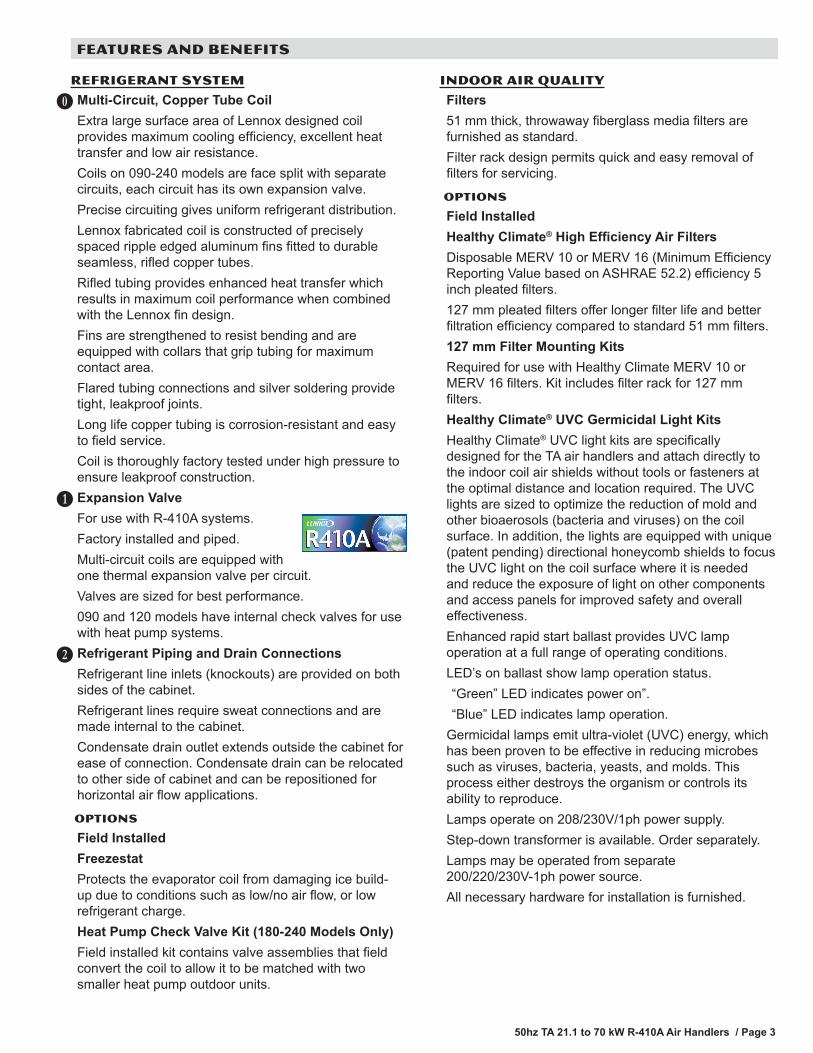
REFRIGERANT SYSTEM
Multi-Circuit, Copper Tube CoilExtra large surface area of Lennox designed coil provides maximum cooling efficiency, excellent heat transfer and low air resistance.Coils on 090-240 models are face split with separate circuits, each circuit has its own expansion valve.Precise circuiting gives uniform refrigerant distribution.Lennox fabricated coil is constructed of precisely spaced ripple edged aluminum fins fitted to durable seamless, rifled copper tubes.Rifled tubing provides enhanced heat transfer which results in maximum coil performance when combined with the Lennox fin design.Fins are strengthened to resist bending and are equipped with collars that grip tubing for maximum contact area.Flared tubing connections and silver soldering provide tight, leakproof joints.Long life copper tubing is corrosion-resistant and easy to field service.Coil is thoroughly factory tested under high pressure to ensure leakproof construction.Expansion ValveFor use with R-410A systems.Factory installed and piped.Multi-circuit coils are equipped with one thermal expansion valve per circuit.Valves are sized for best performance.090 and 120 models have internal check valves for use with heat pump systems.Refrigerant Piping and Drain ConnectionsRefrigerant line inlets (knockouts) are provided on both sides of the cabinet.Refrigerant lines require sweat connections and are made internal to the cabinet.Condensate drain outlet extends outside the cabinet for ease of connection. Condensate drain can be relocated to other side of cabinet and can be repositioned for horizontal air flow applications.
OPTIONS
Field InstalledFreezestatProtects the evaporator coil from damaging ice build-up due to conditions such as low/no air flow, or low refrigerant charge.Heat Pump Check Valve Kit (180-240 Models Only)Field installed kit contains valve assemblies that field convert the coil to allow it to be matched with two smaller heat pump outdoor units.
A
B
C
INDOOR AIR QUALITY
Filters51 mm thick, throwaway fiberglass media filters are furnished as standard.Filter rack design permits quick and easy removal of filters for servicing.
OPTIONS
Field InstalledHealthy Climate® High Efficiency Air FiltersDisposable MERV 10 or MERV 16 (Minimum Efficiency Reporting Value based on ASHRAE 52.2) efficiency 5 inch pleated filters.127 mm pleated filters offer longer filter life and better filtration efficiency compared to standard 51 mm filters.127 mm Filter Mounting KitsRequired for use with Healthy Climate MERV 10 or MERV 16 filters. Kit includes filter rack for 127 mm filters.Healthy Climate® UVC Germicidal Light KitsHealthy Climate® UVC light kits are specifically designed for the TA air handlers and attach directly to the indoor coil air shields without tools or fasteners at the optimal distance and location required. The UVC lights are sized to optimize the reduction of mold and other bioaerosols (bacteria and viruses) on the coil surface. In addition, the lights are equipped with unique (patent pending) directional honeycomb shields to focus the UVC light on the coil surface where it is needed and reduce the exposure of light on other components and access panels for improved safety and overall effectiveness.Enhanced rapid start ballast provides UVC lamp operation at a full range of operating conditions.LED’s on ballast show lamp operation status.“Green” LED indicates power on”.“Blue” LED indicates lamp operation.
Germicidal lamps emit ultra-violet (UVC) energy, which has been proven to be effective in reducing microbes such as viruses, bacteria, yeasts, and molds. This process either destroys the organism or controls its ability to reproduce.Lamps operate on 208/230V/1ph power supply.Step-down transformer is available. Order separately.Lamps may be operated from separate 200/220/230V-1ph power source.All necessary hardware for installation is furnished.

50hz TA 21.1 to 70 kW R-410A Air Handlers / Page 4
FEATURES AND BENEFITS
BELT DRIVE BLOWERS
072-090-120-150 models are equipped with a single blower wheel, 180 and 240 models have dual blower wheels.Centrifugal belt driven blowers deliver large air volumes quietly and with low power consumption.Blower wheels are heavy-duty, with forward curved blades and double inlet.Wheels are statically and dynamically balanced to eliminate vibration and designed to give maximum air delivery.Bearings are heavy-duty, permanently sealed and lubricated.Belt tension is automatically controlled by auto tensioning device.Adjustable motor pulley allows speed adjustments.Standard static drive is furnished factory installed. See Blower Drive Specifications table for optional factory installed low and high static drives available.
OPTIONS
Factory InstalledLow or High Static DrivesA choice of optional low or high static drives are available for factory installation. See Blower Drive Specifications table.
CONTROLS
Control BoxControl box located in separate compartment in unit cabinet.Box may be relocated to alternate location for easier access depending on application. See dimension drawings.Low voltage terminal strip factory installed.Blower contactor furnished and factory installed in control box.All controls are pre-wired at the factory.
D
E
CABINET
Cabinet is constructed of heavy-gauge, galvanized steel.Cabinet is completely lined with thick fiberglass insulation resulting in quiet and efficient operation due to the excellent sound deadening and insulating qualities of fiberglass.Supply and return air duct flanges are furnished for field installation. See dimension drawings.Service access is provided on three sides (072-150) and four sides (180-240) of unit.Large removable panels provide complete service access on one side of unit.Electrical inlets are conveniently located in the cabinet. See dimension drawingsDrain PanDeep, corrosion resistant plastic drain pan.Reversible drain pan allows for drain outlets on either end of cabinet and can be repositioned for horizontal air flow applications.Drain pan is removable from either side in both horizontal and vertical applications.
OPTIONS
Factory InstalledCorrosion ProtectionPolymeric epoxy coating that is deposited by electrical transport (electrophoresis), using a process known as electrocoat (e-coat). Available for enhanced coil corrosion protection. Factory installed on the indoor coil. Blower housing is painted when this option is ordered.Field InstalledFloat SwitchPrevents condensate overflow by turning the unit off when the condensate level is abnormally high.Return Air GrillesAnodized aluminum grille field installs in return air opening of air handler.Return Air Grille Free AreaT2GARD30L-1 - 0.38 m2.T2GARD30M-1 - 0.55 m2.T2GARD30N-1 - 0.71 m2.
F
G

50hz TA 21.1 to 70 kW R-410A Air Handlers / Page 5
ELECTRIC HEAT SECTION
Furnished in a separate add-on matching cabinet.Mounting hardware is furnished to secure cabinets together.Pre-punched mounting holes are furnished for aligning electric heat section to air handler supply air flange.Removable panel permits service access.Electrical inlet provides wiring entry.Field installed electric heaters are available in several kW sizes, see Electric Heat Data table.Helix wound, nichrome heating elements are exposed directly in the air stream resulting in instant heat transfer, lower coil temperatures and long service life.Elements are accurately located and insulated from the heavy-gauge steel support frame by high quality insulators.Elements are equipped with individual limit controls providing positive protection in case of overheating.Sub-fusing, contactors, control relays, 24V transformer are furnished.Certain electric heat sizes may be two-stage controlled (with field provided control) with each stage being energized only when required. See Electric Heat Tables.
HOT WATER COIL
Furnished in a separate add-on matching cabinet.Mounting hardware is furnished to secure cabinets together.Pre-punched mounting holes are furnished for aligning cabinet to air handler.Cabinet is constructed of heavy-gauge galvanized steel.Completely insulated with thick, foil-faced fiberglass insulation.Removable panel permits service access.Cabinet is reversible to allow piping on either side of unit.Lennox designed and built coil has large face area, excellent heat transfer and low air resistance.Constructed of precisely spaced ripple-edged aluminum fins fitted to durable copper tubes.Fins are equipped with collars that grip tubing for maximum contact area.Flared shoulder tubing connections and silver soldering provide tight, leakproof joints.Long life copper tubing is easy to field service.Coil is thoroughly factory tested under high pressure to ensure leakproof construction.Valves and pumps must be furnished by installer.
ECONOMIZER DAMPER SECTION
Factory assembled and wired economizer dampers and controls are available for field installation.Heavy-gauge galvanized steel cabinet is completely insulated with thick, matte-faced fiberglass insulation.Large removable panels on both sides of cabinet provide complete service access.Mounting flanges provide ease of connection to air handler unit.Flanges on outdoor air opening and return air opening permit easy duct connection.Economizer has mechanically linked outdoor air and recirculated air dampers.Formed dampers rotate smoothly in nylon bearings.Outdoor air dampers are reinforced and gasketed for tight seal and quiet operation.Damper linkage and shafts are plated.The positioning of the dampers is accomplished by a 24V fully-modulating, electronic spring return damper motor with adjustable minimum position potentiometer and controlled by the room thermostat, adjustable mixed air sensor and adjustable enthalpy control.The enthalpy control allows 0 to 100% outdoor air to be used for free cooling” when outdoor temperature and humidity are acceptable.Differential Enthalpy ControlAn optional, return air enthalpy sensor can be ordered extra for field installation. Allows the outdoor air enthalpy control to select between outdoor air or return air, whichever has lower enthalpy. Field installed in economizer damper section.
OPTIONS / ACCESSORIES

50hz TA 21.1 to 70 kW R-410A Air Handlers / Page 6
OPTIONS / ACCESSORIES Item Catalog
No.072 090 120 150 180 240
BLOWER
Blower Drives See Blower Drive Specifications Table on page 14
CABINET
Corrosion Protection Factory O O O O O OFloat Switch T2SNSR71LN1- 47W40 X X X X X XReturn Air Grille T2GARD30L-1 47W49 X X
T2GARD30M-1 47W50 X XT2GARD30N-1 47W51 X X
NOTE - The catalog and model numbers that appear here are for ordering field installed accessories only. O - Factory Installed with extended lead time. X - Field Installed.
1 Corrosion protection option requires extended lead time.
SPECIFICATIONSGeneral Data
Model No. TAA150S4D TAA180S4D TAA240S4DNominal kW 44.0 53 70
Connections Liquid line o.d. - mm (in.) (sweat) (2) 16 (5/8) (2) 16 (5/8) (2) 16 (5/8)Suction/Vapor line o.d. - mm (in.) (sweat) (2) 22 (7/8) (2) 28.5 (1-1/8) (2) 28.5 (1-1/8)
Condensate drain - in. (fpt) 1 (NPT) 1 (NPT) 1 (NPT)Refrigerant Not Furnished R-410A R-410A R-410AEvaporator Coil
Net face area - m2 (ft2) 1.05 (11.3) 1.57 (16.9) 1.57 (16.9)Coil (Face) Split - 1st stage / 2nd stage (%) 50 / 50 50 / 50 50 / 50
Tube diameter - mm (in.) 9.5 (3/8) 9.5 (3/8) 9.5 (3/8)Number of rows 4 3 4
Fins per Meter (Fins per inch) 551 (14) 551 (14) 551 (14)Blower and Drive
See Blower Drive Specifications Table on page 14Wheel nominal diameter & width - mm (in.) (1) 381 x 381 (15 x 15) (2) 381 x 381 (15 x 15)
Filter Number and size - mm (in.) (4) 406 x 635 x 51 (16 x 25 x 2)
SPECIFICATIONS General Data
Model No. TAA072S4S TAA090S4D TAA120S4DNominal kW 21.0 26.4 35.2
Connections Liquid line o.d. - mm (in.) (sweat) (1) 16 (5/8) (2) 16 (5/8) (2) 16 (5/8)Suction/Vapor line o.d. - mm (in.) (sweat) (1) 28.5 (1-1/8) (2) 22 (7/8) (2) 22 (7/8)
Condensate drain - in. (fpt) 1 (NPT) 1 (NPT) 1 (NPT)Refrigerant Not Furnished R-410A R-410A R-410AEvaporator Coil
Net face area - m2 (ft2) 0.76 (8.2) 0.76 (8.2) 1.05 (11.3)Coil (Face) Split - 1st stage / 2nd stage (%) - - - 50 / 50 50 / 50
Tube diameter - mm (in.) 9.5 (3/8) 9.5 (3/8) 9.5 (3/8)Number of rows 3 4 4
Fins per Meter (Fins per inch) 551 (14) 551 (14) 551 (14)Blower and Drive
See Blower Drive Specifications Table on page 14Wheel nominal diameter & width - mm (in.) (1) 381 x 381 (15 x 15)
Filter Number and size - mm (in.) (3) 406 x 635 x 51 (16 x 25 x 2) (4) 406 x 635 x 51 (16 x 25 x 2)

50hz TA 21.1 to 70 kW R-410A Air Handlers / Page 7
OPTIONS / ACCESSORIES Item Catalog
No.072 090 120 150 180 240
1 ELECTRIC HEAT6.9 kW 380/420V-3ph - T3EH0010LM1G 46W55 X X X X10.4 kW 380/420V-3ph - T3EH0015LM1G 46W56 X x X X17.4 kW 380/420V-3ph - T3EH0025LM1G 46W57 X X X X24.3 kW 380/420V-3ph - T3EH0035LM1G 46W58 X X X15.3 kW 380/420V-3ph - T3EH0020N-1G 46W69 X X23.0 kW 380/420V-3ph - T3EH0030N-1G 46W70 X X30.6 kW 380/420V-3ph - T3EH0040N-1G 46W40 X X38.3 kW 380/420V-3ph - T3EH0050N-1G 46W71 X XECONOMIZER
T2ECON31L-1- 44W94 X XT2ECON31M-1- 44W95 X XT2ECON31N-1- 44W96 X X
Economizer ControlsDifferential Enthalpy Control 17W71 X X X X X XHOT WATER COIL
T2HWCL10LM1- 44W20 X X X XT2HWCL10N-1- 44W21 X X
INDOOR AIR QUALITYAir Filters
2 Healthy Climate®
High Efficiency Air Filters 406 x 635 x127 mm (16 x 25 x 5 in.)
MERV 10 - HCF16-10 X6670 X X X X X XMERV 16 - HCF16-16 X6672 X X X X X X
127 mm Filter Mounting Kits T2FLTR70L-1- 47W71 X XT2FLTR70M-1- 47W72 X XT2FLTR70N-1- 47W73 X X
Healthy Climate® UVC Light Kit (208/230V-1ph)
3 208/230V - T2UVCL10LM1 46W43 X X X X3 208/230V - T2UVCL10N-1 46W44 X X
Step-Down Transformer 96M07 X X X X X XREFRIGERANT SYSTEMFreezestat T2SNSR70N1- 47W41 X X X X X XHeat Pump Check Valve Kit T2CVLV10N-1- 47W48 X
T2CVLV11N-1- 50W73 XNOTE - The catalog and model numbers that appear here are for ordering field installed accessories only.
X - Field Installed.1 Nominal kW at 400V/3ph/50hz. Electric heat model numbers are based on nominal kW for US applications.2 Order 127 mm (5 in.) Filter Mounting Kit and required number of MERV 10 or MERV 16 filters: - (3) 072-090, (4) 120-150.3 Step-down transformer (380/420V to 190/210V-1ph) or separate power supply is required.

50hz TA 21.1 to 70 kW R-410A Air Handlers / Page 8
BLOWER DATA
TAA072 BLOWER PERFORMANCEAll data is measured external to the unit with dry coil and standard 51 mm (2 in.) air filters in place. FOR ALL UNITS ADD: 1 - Wet indoor coil air resistance of selected unit. 2 - Any field installed accessories air resistance (electric heat, economizer, etc.) See page 15. Then determine from table the blower motor hp and drive rpm required. See page 14 for blower drive specifications.
Air Volume
STATIC PRESSURE EXTERNAL TO UNIT - Pa (Inches Water Gauge)
25 (0.1) 50 (0.2) 75 (0.3) 100 (0.4) 125 (0.5) 150 (0.6) 175 (0.7) 200 (0.8)
L/s CFM Rev/min
kW BHP Rev/min
kW BHPRev/min
kW BHPRev/min
kW BHPRev/min
kW BHPRev/min
kW BHPRev/min
kW BHPRev/min
kW BHP
895 1900 428 0.43 0.57 479 0.49 0.66 531 0.55 0.74 581 0.60 0.81 629 0.66 0.88 675 0.70 0.94 718 0.75 1.01 758 0.80 1.07
945 2000 434 0.44 0.59 486 0.51 0.69 538 0.57 0.77 589 0.63 0.84 637 0.68 0.91 682 0.73 0.98 725 0.78 1.05 765 0.83 1.11
990 2100 441 0.46 0.62 493 0.54 0.72 545 0.60 0.80 596 0.66 0.88 644 0.71 0.95 689 0.76 1.02 732 0.81 1.09 771 0.86 1.15
1040 2200 448 0.48 0.65 501 0.56 0.75 553 0.62 0.83 604 0.68 0.91 652 0.73 0.98 696 0.79 1.06 738 0.84 1.13 778 0.90 1.20
1085 2300 456 0.51 0.68 508 0.58 0.78 561 0.64 0.86 612 0.70 0.94 659 0.76 1.02 704 0.82 1.10 746 0.87 1.17 785 0.93 1.24
1135 2400 463 0.53 0.71 516 0.60 0.81 569 0.67 0.90 620 0.73 0.98 667 0.79 1.06 711 0.85 1.14 753 0.91 1.22 792 0.96 1.29
1180 2500 470 0.55 0.74 524 0.63 0.84 578 0.70 0.94 629 0.76 1.02 675 0.82 1.10 719 0.89 1.19 760 0.95 1.27 798 1.00 1.34
1225 2600 478 0.57 0.77 533 0.66 0.88 587 0.73 0.98 637 0.79 1.06 683 0.86 1.15 726 0.93 1.24 767 0.98 1.32 805 1.04 1.39
1275 2700 486 0.60 0.81 542 0.69 0.92 596 0.76 1.02 646 0.83 1.11 692 0.90 1.20 734 0.96 1.29 775 1.02 1.37 812 1.08 1.45
1320 2800 495 0.63 0.85 552 0.72 0.96 606 0.80 1.07 655 0.87 1.16 700 0.93 1.25 742 1.00 1.34 782 1.06 1.42 819 1.12 1.50
1370 2900 504 0.66 0.89 561 0.75 1.01 616 0.83 1.11 665 0.90 1.20 708 0.97 1.30 750 1.04 1.39 789 1.10 1.48 826 1.16 1.56
1415 3000 514 0.69 0.93 572 0.78 1.05 626 0.87 1.16 674 0.94 1.26 717 1.01 1.35 758 1.08 1.45 797 1.15 1.54 833 1.21 1.62
Air Volume
STATIC PRESSURE EXTERNAL TO UNIT - Pa (Inches Water Gauge)
225 (0.9) 250 (1.0) 275 (1.1) 300 (1.2) 325 (1.3) 350 (1.4) 375 (1.5)
L/s CFM Rev/min
kW BHP Rev/min
kW BHP Rev/min
kW BHP Rev/min
kW BHP Rev/min
kW BHP Rev/min
kW BHP Rev/min
kW BHP
895 1900 796 0.84 1.13 830 0.89 1.19 862 0.93 1.25 893 0.98 1.32 922 1.04 1.39 950 1.09 1.46 978 1.15 1.54
945 2000 802 0.87 1.17 836 0.92 1.23 868 0.97 1.30 898 1.02 1.37 928 1.07 1.44 956 1.13 1.52 983 1.19 1.60
990 2100 808 0.91 1.22 842 0.95 1.28 874 1.01 1.35 904 1.06 1.42 933 1.12 1.50 961 1.18 1.58 988 1.24 1.66
1040 2200 814 0.94 1.26 848 0.99 1.33 879 1.04 1.40 909 1.10 1.48 938 1.16 1.56 966 1.22 1.64 993 1.29 1.73
1085 2300 820 0.98 1.31 854 1.03 1.38 885 1.09 1.46 915 1.14 1.53 943 1.21 1.62 971 1.27 1.70 998 1.34 1.79
1135 2400 827 1.01 1.36 860 1.07 1.43 891 1.13 1.51 920 1.19 1.59 949 1.25 1.68 976 1.32 1.77 1003 1.39 1.86
1180 2500 833 1.05 1.41 866 1.11 1.49 897 1.17 1.57 926 1.24 1.66 954 1.31 1.75 981 1.37 1.84 1008 1.44 1.93
1225 2600 840 1.10 1.47 872 1.16 1.55 902 1.22 1.63 932 1.28 1.72 960 1.35 1.81 987 1.42 1.91 1013 1.50 2.01
1275 2700 846 1.14 1.53 878 1.20 1.61 908 1.27 1.70 937 1.34 1.79 965 1.40 1.88 992 1.48 1.98 1018 1.55 2.08
1320 2800 853 1.18 1.58 884 1.25 1.67 914 1.31 1.76 943 1.39 1.86 970 1.46 1.96 997 1.54 2.06 1023 1.61 2.16
1370 2900 859 1.23 1.65 890 1.30 1.74 920 1.37 1.83 948 1.44 1.93 975 1.51 2.03 1002 1.60 2.14 1028 1.67 2.24
1415 3000 866 1.28 1.71 896 1.34 1.80 926 1.42 1.90 954 1.49 2.00 981 1.57 2.11 1007 1.66 2.22 1032 1.74 2.33

50hz TA 21.1 to 70 kW R-410A Air Handlers / Page 9
BLOWER DATA
TAA090 BLOWER PERFORMANCEAll data is measured external to the unit with dry coil and standard 51 mm (2 in.) air filters in place. FOR ALL UNITS ADD: 1 - Wet indoor coil air resistance of selected unit. 2 - Any field installed accessories air resistance (electric heat, economizer, etc.) See page 15. Then determine from table the blower motor hp and drive rpm required. See page 14 for blower drive specifications.
Air Volume
STATIC PRESSURE EXTERNAL TO UNIT - Pa (Inches Water Gauge)
25 (0.1) 50 (0.2) 75 (0.3) 100 (0.4) 125 (0.5) 150 (0.6) 175 (0.7) 200 (0.8)
L/s CFM Rev/min
kW BHP Rev/min
kW BHPRev/min
kW BHPRev/min
kW BHPRev/min
kW BHPRev/min
kW BHPRev/min
kW BHPRev/min
kW BHP
1135 2400 508 0.59 0.79 565 0.66 0.89 619 0.73 0.98 667 0.79 1.06 710 0.85 1.14 750 0.92 1.23 787 0.97 1.30 822 1.03 1.38
1180 2500 519 0.62 0.83 577 0.70 0.94 630 0.76 1.02 677 0.82 1.10 720 0.89 1.19 759 0.95 1.28 796 1.01 1.36 830 1.07 1.43
1225 2600 531 0.65 0.87 588 0.73 0.98 641 0.80 1.07 688 0.87 1.16 729 0.93 1.25 769 1.00 1.34 805 1.06 1.42 839 1.11 1.49
1275 2700 543 0.69 0.92 600 0.77 1.03 653 0.84 1.12 698 0.90 1.21 739 0.98 1.31 778 1.04 1.40 814 1.10 1.48 848 1.16 1.55
1320 2800 555 0.72 0.97 613 0.81 1.08 664 0.87 1.17 709 0.95 1.27 749 1.02 1.37 788 1.09 1.46 824 1.15 1.54 857 1.21 1.62
1370 2900 568 0.76 1.02 625 0.84 1.13 676 0.91 1.22 719 0.98 1.32 759 1.07 1.43 797 1.13 1.52 833 1.19 1.60 866 1.25 1.68
1415 3000 581 0.80 1.07 638 0.88 1.18 687 0.95 1.28 730 1.04 1.39 769 1.11 1.49 807 1.18 1.58 842 1.25 1.67 875 1.31 1.75
1465 3100 595 0.84 1.12 651 0.93 1.24 699 1.00 1.34 740 1.08 1.45 779 1.16 1.56 817 1.23 1.65 852 1.29 1.73 883 1.36 1.82
1510 3200 609 0.88 1.18 664 0.97 1.30 710 1.05 1.41 751 1.13 1.52 789 1.22 1.63 827 1.28 1.72 861 1.34 1.80 892 1.41 1.89
1555 3300 624 0.93 1.24 677 1.01 1.36 722 1.10 1.48 761 1.19 1.59 799 1.27 1.70 836 1.34 1.79 870 1.40 1.88 901 1.47 1.97
1605 3400 639 0.97 1.30 690 1.07 1.43 733 1.16 1.55 772 1.25 1.67 810 1.32 1.77 846 1.39 1.86 879 1.45 1.95 909 1.53 2.05
1650 3500 653 1.02 1.37 703 1.12 1.50 745 1.21 1.62 782 1.31 1.75 820 1.38 1.85 856 1.45 1.94 888 1.51 2.03 917 1.60 2.14
1700 3600 668 1.07 1.44 715 1.17 1.57 756 1.27 1.70 793 1.37 1.83 830 1.44 1.93 865 1.51 2.02 897 1.58 2.12 925 1.67 2.24
Air Volume
STATIC PRESSURE EXTERNAL TO UNIT - Pa (Inches Water Gauge)
225 (0.9) 250 (1.0) 275 (1.1) 300 (1.2) 325 (1.3) 350 (1.4) 375 (1.5)
L/s CFM Rev/min
kW BHP Rev/min
kW BHP Rev/min
kW BHP Rev/min
kW BHP Rev/min
kW BHP Rev/min
kW BHP Rev/min
kW BHP
1135 2400 855 1.07 1.44 888 1.13 1.51 920 1.19 1.59 950 1.25 1.67 979 1.32 1.77 1006 1.39 1.86 1033 1.46 1.96
1180 2500 863 1.12 1.50 896 1.17 1.57 928 1.23 1.65 958 1.30 1.74 986 1.37 1.84 1013 1.45 1.94 1039 1.52 2.04
1225 2600 872 1.16 1.56 904 1.22 1.64 936 1.28 1.72 965 1.36 1.82 993 1.43 1.92 1019 1.51 2.02 1045 1.58 2.12
1275 2700 880 1.21 1.62 913 1.27 1.70 943 1.34 1.79 972 1.41 1.89 1000 1.49 2.00 1026 1.57 2.10 1052 1.64 2.20
1320 2800 889 1.26 1.69 921 1.32 1.77 951 1.40 1.87 979 1.47 1.97 1006 1.55 2.08 1033 1.63 2.18 1058 1.71 2.29
1370 2900 898 1.31 1.76 929 1.38 1.85 959 1.45 1.95 987 1.53 2.05 1013 1.61 2.16 1039 1.69 2.26 1064 1.77 2.37
1415 3000 906 1.37 1.83 937 1.44 1.93 966 1.51 2.03 994 1.59 2.13 1020 1.67 2.24 1046 1.75 2.35 1070 1.84 2.46
1465 3100 914 1.42 1.91 944 1.50 2.01 973 1.57 2.11 1001 1.66 2.22 1027 1.74 2.33 1052 1.82 2.44 1077 1.90 2.55
1510 3200 922 1.48 1.99 952 1.56 2.09 980 1.64 2.20 1008 1.72 2.30 1033 1.80 2.41 1058 1.89 2.53 1083 1.97 2.64
1555 3300 930 1.54 2.07 959 1.63 2.18 987 1.71 2.29 1014 1.78 2.39 1040 1.87 2.50 1065 1.95 2.62 1089 2.04 2.73
1605 3400 938 1.61 2.16 966 1.69 2.27 994 1.78 2.38 1021 1.86 2.49 1046 1.94 2.60 1071 2.02 2.71 1095 2.11 2.83
1650 3500 945 1.69 2.26 973 1.77 2.37 1001 1.85 2.48 1028 1.92 2.58 1053 2.01 2.69 1077 2.10 2.81 1101 2.19 2.93
1700 3600 953 1.75 2.35 980 1.84 2.47 1008 1.92 2.58 1034 2.00 2.68 1059 2.08 2.79 1084 2.17 2.91 1107 2.26 3.03

50hz TA 21.1 to 70 kW R-410A Air Handlers / Page 10
BLOWER DATA
TAA120 BLOWER PERFORMANCEAll data is measured external to the unit with dry coil and standard 51 mm (2 in.) air filters in place. FOR ALL UNITS ADD: 1 - Wet indoor coil air resistance of selected unit. 2 - Any field installed accessories air resistance (electric heat, economizer, etc.) See page 15. Then determine from table the blower motor hp and drive rpm required. See page 14 for blower drive specifications.
Air Volume
STATIC PRESSURE EXTERNAL TO UNIT - Pa (Inches Water Gauge)
25 (0.1) 50 (0.2) 75 (0.3) 100 (0.4) 125 (0.5) 150 (0.6) 175 (0.7) 200 (0.8)
L/s CFM Rev/min
kW BHP Rev/min
kW BHPRev/min
kW BHPRev/min
kW BHPRev/min
kW BHPRev/min
kW BHPRev/min
kW BHPRev/min
kW BHP
1415 3000 484 0.38 0.51 516 0.45 0.60 552 0.52 0.70 591 0.61 0.82 635 0.71 0.95 677 0.80 1.07 699 0.82 1.10 736 0.88 1.18
1510 3200 499 0.46 0.62 531 0.52 0.70 566 0.60 0.80 606 0.69 0.92 651 0.79 1.06 684 0.86 1.15 707 0.88 1.18 746 0.95 1.28
1605 3400 514 0.54 0.73 546 0.60 0.81 582 0.68 0.91 622 0.77 1.03 667 0.87 1.17 690 0.91 1.22 717 0.96 1.29 758 1.04 1.40
1700 3600 529 0.63 0.84 562 0.69 0.93 598 0.77 1.03 639 0.86 1.15 679 0.95 1.28 697 0.98 1.31 730 1.04 1.40 772 1.13 1.52
1795 3800 545 0.72 0.96 579 0.78 1.05 616 0.86 1.15 658 0.95 1.28 686 1.02 1.37 706 1.05 1.41 745 1.14 1.53 786 1.23 1.65
1890 4000 562 0.81 1.09 596 0.88 1.18 634 0.96 1.29 674 1.05 1.41 693 1.09 1.46 720 1.15 1.54 761 1.25 1.67 802 1.34 1.79
1980 4200 580 0.92 1.23 615 0.98 1.31 654 1.06 1.42 684 1.13 1.52 702 1.17 1.57 737 1.26 1.69 778 1.36 1.82 819 1.45 1.94
2075 4400 600 1.02 1.37 635 1.08 1.45 672 1.16 1.56 691 1.21 1.62 717 1.28 1.72 756 1.39 1.86 796 1.48 1.98 836 1.56 2.09
2170 4600 619 1.13 1.51 655 1.19 1.59 683 1.25 1.68 702 1.31 1.76 736 1.41 1.89 775 1.51 2.02 814 1.59 2.13 853 1.67 2.24
2265 4800 639 1.23 1.65 673 1.29 1.73 692 1.35 1.81 719 1.44 1.93 757 1.55 2.08 795 1.63 2.19 832 1.72 2.30 871 1.79 2.40
2360 5000 659 1.33 1.78 685 1.40 1.87 706 1.47 1.97 740 1.58 2.12 778 1.69 2.26 814 1.77 2.37 851 1.84 2.46 889 1.91 2.56
Air Volume
STATIC PRESSURE EXTERNAL TO UNIT - Pa (Inches Water Gauge)
225 (0.9) 250 (1.0) 275 (1.1) 300 (1.2) 325 (1.3) 350 (1.4) 375 (1.5)
L/s CFM Rev/min
kW BHP Rev/min
kW BHP Rev/min
kW BHP Rev/min
kW BHP Rev/min
kW BHP Rev/min
kW BHP Rev/min
kW BHP
1415 3000 779 0.96 1.29 826 1.06 1.42 873 1.16 1.56 919 1.27 1.70 964 1.37 1.84 1009 1.48 1.98 1054 1.57 2.11
1510 3200 790 1.04 1.40 836 1.14 1.53 882 1.24 1.66 929 1.34 1.80 974 1.45 1.94 1019 1.54 2.07 1063 1.65 2.21
1605 3400 802 1.13 1.51 847 1.22 1.64 893 1.32 1.77 938 1.42 1.91 983 1.52 2.04 1028 1.62 2.17 1072 1.72 2.31
1700 3600 815 1.22 1.64 859 1.31 1.76 904 1.41 1.89 949 1.51 2.03 993 1.61 2.16 1037 1.71 2.29 1080 1.81 2.42
1795 3800 829 1.32 1.77 873 1.42 1.90 917 1.51 2.03 961 1.61 2.16 1005 1.71 2.29 1048 1.81 2.42 1090 1.90 2.55
1890 4000 845 1.42 1.91 888 1.52 2.04 932 1.62 2.17 975 1.72 2.31 1018 1.81 2.43 1060 1.91 2.56 1102 2.01 2.69
1980 4200 861 1.54 2.06 904 1.63 2.19 948 1.73 2.32 990 1.84 2.46 1033 1.93 2.59 1074 2.02 2.71 1116 2.12 2.84
2075 4400 878 1.65 2.21 921 1.75 2.34 963 1.84 2.47 1006 1.94 2.60 1048 2.04 2.73 1089 2.13 2.86 1130 2.22 2.98
2170 4600 894 1.76 2.36 936 1.86 2.49 979 1.95 2.61 1021 2.04 2.74 1063 2.14 2.87 1104 2.24 3.00 1145 2.33 3.12
2265 4800 911 1.87 2.51 953 1.96 2.63 995 2.06 2.76 1036 2.15 2.88 1078 2.25 3.01 1119 2.33 3.13 1161 2.43 3.26
2360 5000 928 1.99 2.67 969 2.07 2.78 1011 2.16 2.90 1052 2.26 3.03 1094 2.35 3.15 1135 2.44 3.27 1176 2.54 3.40

50hz TA 21.1 to 70 kW R-410A Air Handlers / Page 11
BLOWER DATA
TAA150 BLOWER PERFORMANCEAll data is measured external to the unit with dry coil and standard 51 mm (2 in.) air filters in place. FOR ALL UNITS ADD: 1 - Wet indoor coil air resistance of selected unit. 2 - Any field installed accessories air resistance (electric heat, economizer, etc.) See page 15. Then determine from table the blower motor hp and drive rpm required. See page 14 for blower drive specifications.
Air Volume
STATIC PRESSURE EXTERNAL TO UNIT - Pa (Inches Water Gauge)
25 (0.1) 50 (0.2) 75 (0.3) 100 (0.4) 125 (0.5) 150 (0.6) 175 (0.7) 200 (0.8)
L/s CFM Rev/min
kW BHP Rev/min
kW BHPRev/min
kW BHPRev/min
kW BHPRev/min
kW BHPRev/min
kW BHPRev/min
kW BHPRev/min
kW BHP
1890 4000 627 0.94 1.26 669 1.04 1.39 690 1.08 1.45 714 1.13 1.52 754 1.23 1.65 795 1.31 1.76 835 1.40 1.87 877 1.48 1.98
1980 4200 653 1.06 1.42 684 1.13 1.52 701 1.17 1.57 736 1.26 1.69 777 1.36 1.82 816 1.43 1.92 856 1.51 2.02 897 1.59 2.13
2075 4400 676 1.17 1.57 694 1.22 1.63 721 1.29 1.73 761 1.40 1.87 800 1.48 1.99 838 1.55 2.08 877 1.63 2.18 917 1.70 2.28
2170 4600 688 1.27 1.70 710 1.34 1.79 747 1.44 1.93 787 1.54 2.06 823 1.61 2.16 860 1.67 2.24 898 1.74 2.33 938 1.81 2.43
2265 4800 702 1.38 1.85 735 1.48 1.99 774 1.60 2.14 812 1.68 2.25 846 1.73 2.32 882 1.79 2.40 920 1.86 2.49 959 1.92 2.58
2360 5000 725 1.54 2.06 763 1.65 2.21 801 1.75 2.34 837 1.82 2.44 869 1.86 2.49 903 1.90 2.55 941 1.97 2.64 979 2.04 2.73
2455 5200 754 1.72 2.30 791 1.81 2.43 828 1.90 2.55 862 1.96 2.63 891 1.98 2.66 925 2.02 2.71 962 2.08 2.79 1000 2.15 2.88
2550 5400 783 1.89 2.53 819 1.98 2.65 855 2.05 2.75 887 2.10 2.82 913 2.10 2.82 946 2.13 2.86 983 2.20 2.95 1021 2.26 3.03
2645 5600 810 2.04 2.74 845 2.13 2.85 881 2.20 2.95 912 2.25 3.01 935 2.22 2.98 967 2.25 3.01 1004 2.31 3.10 1041 2.38 3.19
2735 5800 835 2.20 2.95 871 2.28 3.05 906 2.35 3.15 936 2.38 3.19 957 2.34 3.14 987 2.36 3.16 1024 2.42 3.25 1062 2.49 3.34
2830 6000 860 2.34 3.14 896 2.42 3.25 931 2.50 3.35 960 2.51 3.37 978 2.46 3.30 1008 2.47 3.31 1045 2.54 3.40 1083 2.60 3.48
Air Volume
STATIC PRESSURE EXTERNAL TO UNIT - Pa (Inches Water Gauge)
225 (0.9) 250 (1.0) 275 (1.1) 300 (1.2) 325 (1.3) 350 (1.4) 375 (1.5)
L/s CFM Rev/min
kW BHP Rev/min
kW BHP Rev/min
kW BHP Rev/min
kW BHP Rev/min
kW BHP Rev/min
kW BHP Rev/min
kW BHP
1890 4000 920 1.57 2.10 963 1.66 2.22 1006 1.75 2.34 1048 1.84 2.46 1091 1.92 2.58 1133 2.01 2.69 1174 2.10 2.81
1980 4200 939 1.67 2.24 982 1.76 2.36 1024 1.85 2.48 1067 1.93 2.59 1109 2.02 2.71 1151 2.11 2.83 1193 2.20 2.95
2075 4400 959 1.78 2.39 1001 1.87 2.50 1043 1.95 2.61 1085 2.04 2.73 1127 2.13 2.85 1169 2.21 2.96 1211 2.30 3.08
2170 4600 979 1.89 2.53 1020 1.97 2.64 1062 2.06 2.76 1104 2.14 2.87 1146 2.23 2.99 1188 2.31 3.10 1230 2.40 3.22
2265 4800 999 2.00 2.68 1040 2.08 2.79 1082 2.16 2.90 1123 2.25 3.01 1165 2.33 3.12 1207 2.42 3.24 1248 2.50 3.35
2360 5000 1019 2.11 2.83 1060 2.19 2.93 1101 2.27 3.04 1142 2.35 3.15 1184 2.43 3.26 1226 2.52 3.38 1267 2.60 3.49
2455 5200 1040 2.22 2.98 1080 2.30 3.08 1121 2.38 3.19 1162 2.45 3.29 1203 2.54 3.41 1245 2.63 3.52 1286 2.71 3.63
2550 5400 1060 2.33 3.13 1100 2.41 3.23 1140 2.48 3.33 1181 2.57 3.44 1222 2.65 3.55 1264 2.73 3.66 1305 2.81 3.77
2645 5600 1080 2.45 3.28 1120 2.51 3.37 1160 2.60 3.48 1201 2.67 3.58 1242 2.75 3.69 1283 2.83 3.80 1324 2.92 3.91
2735 5800 1101 2.56 3.43 1140 2.63 3.52 1180 2.70 3.62 1220 2.78 3.72 1261 2.86 3.83 1302 2.94 3.94 1343 3.02 4.05
2830 6000 1121 2.66 3.57 1160 2.74 3.67 1200 2.81 3.77 1240 2.89 3.87 1280 2.96 3.97 1321 3.04 4.08 1362 3.13 4.19

50hz TA 21.1 to 70 kW R-410A Air Handlers / Page 12
BLOWER DATA
TAA180 BLOWER PERFORMANCEAll data is measured external to the unit with dry coil and standard 51 mm (2 in.) air filters in place. FOR ALL UNITS ADD: 1 - Wet indoor coil air resistance of selected unit. 2 - Any field installed accessories air resistance (electric heat, economizer, etc.) See page 16. Then determine from table the blower motor hp and drive rpm required. See page 14 for blower drive specifications.
Air Volume
STATIC PRESSURE EXTERNAL TO UNIT - Pa (Inches Water Gauge)
25 (0.1) 50 (0.2) 75 (0.3) 100 (0.4) 125 (0.5) 150 (0.6) 175 (0.7) 200 (0.8)
L/s CFM Rev/min
kW BHP Rev/min
kW BHPRev/min
kW BHPRev/min
kW BHPRev/min
kW BHPRev/min
kW BHPRev/min
kW BHPRev/min
kW BHP
2265 4800 440 0.58 0.78 486 0.87 1.16 534 1.09 1.46 582 1.27 1.7 628 1.42 1.9 670 1.54 2.07 709 1.63 2.18 744 1.67 2.24
2360 5000 446 0.66 0.88 492 0.93 1.25 540 1.15 1.54 588 1.32 1.77 634 1.47 1.97 676 1.60 2.14 714 1.69 2.26 748 1.75 2.34
2455 5200 452 0.73 0.98 499 1.00 1.34 547 1.21 1.62 595 1.37 1.84 640 1.52 2.04 682 1.66 2.22 719 1.75 2.34 753 1.81 2.43
2550 5400 458 0.81 1.08 505 1.07 1.43 554 1.27 1.7 602 1.43 1.92 647 1.58 2.12 688 1.72 2.3 724 1.82 2.44 757 1.89 2.54
2645 5600 465 0.88 1.18 512 1.13 1.52 561 1.32 1.77 609 1.48 1.99 653 1.64 2.2 694 1.78 2.39 729 1.89 2.53 762 1.98 2.65
2735 5800 471 0.95 1.28 519 1.20 1.61 568 1.38 1.85 616 1.54 2.07 660 1.70 2.28 700 1.85 2.48 734 1.97 2.64 766 2.07 2.77
2830 6000 478 1.03 1.38 526 1.27 1.7 575 1.44 1.93 623 1.60 2.15 667 1.77 2.37 706 1.92 2.58 740 2.06 2.76 771 2.17 2.91
2925 6200 485 1.10 1.48 534 1.34 1.79 583 1.50 2.01 630 1.66 2.23 674 1.84 2.46 712 2.01 2.69 745 2.15 2.88 776 2.28 3.05
3020 6400 493 1.19 1.59 542 1.40 1.88 591 1.57 2.1 638 1.73 2.32 681 1.91 2.56 718 2.10 2.81 750 2.25 3.01 780 2.39 3.2
3115 6600 500 1.26 1.69 550 1.46 1.96 599 1.63 2.18 646 1.80 2.41 688 1.99 2.67 724 2.19 2.93 755 2.36 3.16 785 2.51 3.36
3210 6800 508 1.34 1.79 558 1.53 2.05 607 1.69 2.27 654 1.87 2.51 695 2.07 2.78 730 2.29 3.07 761 2.48 3.32 789 2.64 3.54
3305 7000 516 1.41 1.89 567 1.60 2.15 616 1.76 2.36 662 1.95 2.61 702 2.17 2.91 736 2.40 3.22 766 2.60 3.49 794 2.78 3.73
3400 7200 525 1.48 1.99 575 1.67 2.24 625 1.84 2.46 670 2.04 2.73 709 2.28 3.05 742 2.52 3.38 771 2.75 3.68 798 2.94 3.94
Air Volume
STATIC PRESSURE EXTERNAL TO UNIT - Pa (Inches Water Gauge)
225 (0.9) 250 (1.0) 275 (1.1) 300 (1.2) 325 (1.3) 350 (1.4) 375 (1.5)
L/s CFM Rev/min
kW BHP Rev/min
kW BHP Rev/min
kW BHP Rev/min
kW BHP Rev/min
kW BHP Rev/min
kW BHP Rev/min
kW BHP
2265 4800 778 1.74 2.33 811 1.84 2.47 844 2.01 2.69 876 2.19 2.94 907 2.37 3.18 936 2.52 3.38 966 2.67 3.58
2360 5000 782 1.81 2.43 814 1.93 2.59 847 2.10 2.81 879 2.29 3.07 909 2.48 3.32 939 2.63 3.53 968 2.80 3.75
2455 5200 786 1.89 2.54 818 2.02 2.71 850 2.20 2.95 881 2.40 3.22 912 2.60 3.48 941 2.76 3.7 970 2.93 3.93
2550 5400 790 1.98 2.66 821 2.13 2.85 853 2.31 3.09 884 2.51 3.37 914 2.72 3.64 943 2.89 3.88 972 3.07 4.12
2645 5600 794 2.08 2.79 825 2.23 2.99 856 2.42 3.24 887 2.64 3.54 917 2.85 3.82 946 3.04 4.07 975 3.23 4.33
2735 5800 798 2.19 2.93 828 2.34 3.14 859 2.54 3.41 890 2.77 3.71 919 2.99 4.01 948 3.19 4.28 977 3.40 4.56
2830 6000 801 2.29 3.07 832 2.46 3.3 862 2.67 3.58 892 2.91 3.9 922 3.15 4.22 951 3.36 4.51 980 3.59 4.81
2925 6200 805 2.41 3.23 835 2.59 3.47 865 2.81 3.77 895 3.07 4.11 924 3.31 4.44 953 3.54 4.75 983 3.78 5.07
3020 6400 809 2.54 3.4 839 2.72 3.65 868 2.96 3.97 898 3.22 4.32 927 3.49 4.68 956 3.74 5.01 986 3.99 5.35
3115 6600 813 2.67 3.58 842 2.87 3.85 872 3.12 4.18 901 3.40 4.56 930 3.68 4.93 959 3.94 5.28 989 4.21 5.65
3210 6800 817 2.81 3.77 846 3.03 4.06 875 3.29 4.41 904 3.58 4.8 933 3.88 5.2 962 4.16 5.58 993 4.45 5.97
3305 7000 821 2.97 3.98 849 3.20 4.29 878 3.48 4.66 907 3.78 5.07 936 4.10 5.49 965 4.39 5.89 996 4.71 6.31
3400 7200 825 3.14 4.21 853 3.38 4.53 881 3.67 4.92 910 3.99 5.35 939 4.32 5.79 969 4.64 6.22 1000 4.98 6.67

50hz TA 21.1 to 70 kW R-410A Air Handlers / Page 13
BLOWER DATA
TAA240 BLOWER PERFORMANCEAll data is measured external to the unit with dry coil and standard 51 mm (2 in.) air filters in place. FOR ALL UNITS ADD: 1 - Wet indoor coil air resistance of selected unit. 2 - Any field installed accessories air resistance (electric heat, economizer, etc.) See page 16. Then determine from table the blower motor hp and drive rpm required. See page 14 for blower drive specifications.
Air Volume
STATIC PRESSURE EXTERNAL TO UNIT - Pa (Inches Water Gauge)25 (0.1) 50 (0.2) 75 (0.3) 100 (0.4) 125 (0.5) 150 (0.6) 175 (0.7) 200 (0.8)
L/s CFM Rev/min
kW BHP Rev/min
kW BHPRev/min
kW BHPRev/min
kW BHPRev/min
kW BHPRev/min
kW BHPRev/min
kW BHPRev/min
kW BHP
3020 6400 535 1.37 1.84 583 1.54 2.06 630 1.70 2.28 674 1.87 2.51 713 2.07 2.77 746 2.26 3.03 776 2.42 3.25 805 2.57 3.443115 6600 545 1.45 1.94 593 1.61 2.16 640 1.78 2.38 683 1.96 2.63 720 2.17 2.91 753 2.38 3.19 782 2.56 3.43 810 2.72 3.643210 6800 555 1.53 2.05 604 1.69 2.27 650 1.87 2.5 692 2.06 2.76 728 2.28 3.06 759 2.51 3.36 787 2.70 3.62 815 2.87 3.853305 7000 566 1.61 2.16 614 1.78 2.38 660 1.95 2.62 701 2.16 2.9 736 2.41 3.23 766 2.65 3.55 793 2.86 3.83 820 3.04 4.083400 7200 577 1.69 2.27 625 1.86 2.49 671 2.05 2.75 710 2.28 3.05 743 2.54 3.4 772 2.80 3.75 799 3.02 4.05 825 3.22 4.323490 7400 588 1.78 2.38 637 1.95 2.61 681 2.15 2.88 719 2.39 3.21 751 2.68 3.59 778 2.95 3.96 804 3.20 4.29 829 3.42 4.583585 7600 600 1.86 2.49 648 2.04 2.74 691 2.26 3.03 727 2.53 3.39 758 2.83 3.79 784 3.12 4.18 809 3.39 4.54 834 3.62 4.853680 7800 613 1.95 2.61 660 2.15 2.88 701 2.38 3.19 735 2.66 3.57 764 2.98 4.0 790 3.30 4.42 814 3.58 4.8 839 3.83 5.143775 8000 626 2.04 2.73 671 2.25 3.02 711 2.51 3.36 743 2.81 3.77 771 3.15 4.22 796 3.48 4.67 819 3.79 5.08 844 4.07 5.453870 8200 638 2.13 2.86 682 2.37 3.18 720 2.65 3.55 751 2.97 3.98 777 3.33 4.46 801 3.68 4.93 824 4.01 5.37 849 4.30 5.773965 8400 651 2.24 3 694 2.50 3.35 729 2.80 3.75 758 3.14 4.21 784 3.51 4.7 807 3.89 5.21 829 4.24 5.68 853 4.57 6.124060 8600 664 2.35 3.15 704 2.63 3.53 738 2.95 3.96 765 3.31 4.44 789 3.71 4.97 812 4.10 5.5 834 4.48 6.0 858 4.83 6.484155 8800 676 2.48 3.32 714 2.78 3.73 746 3.13 4.19 772 3.51 4.7 795 3.92 5.25 817 4.33 5.81 839 4.74 6.35 863 5.12 6.864245 9000 688 2.61 3.5 724 2.94 3.94 754 3.30 4.43 778 3.71 4.97 800 4.13 5.54 822 4.57 6.13 844 5.01 6.71 868 5.42 7.274340 9200 700 2.77 3.71 733 3.11 4.17 761 3.50 4.69 784 3.92 5.26 806 4.37 5.86 826 4.83 6.48 848 5.29 7.09 873 5.74 7.694435 9400 711 2.93 3.93 742 3.30 4.43 768 3.71 4.97 790 4.16 5.57 811 4.62 6.19 831 5.11 6.85 853 5.60 7.5 878 6.08 8.154530 9600 721 3.11 4.17 750 3.51 4.71 775 3.94 5.28 796 4.40 5.9 816 4.89 6.56 836 5.41 7.25 858 5.92 7.94 884 6.44 8.63
Air Volume
STATIC PRESSURE EXTERNAL TO UNIT - Pa (Inches Water Gauge)225 (0.9) 250 (1.0) 275 (1.1) 300 (1.2) 325 (1.3) 350 (1.4) 375 (1.5)
L/s CFM Rev/min
kW BHP Rev/min
kW BHP Rev/min
kW BHP Rev/min
kW BHP Rev/min
kW BHP Rev/min
kW BHP Rev/min
kW BHP
3020 6400 833 2.73 3.66 863 2.92 3.92 892 3.16 4.24 922 3.42 4.59 952 3.68 4.93 981 3.94 5.28 1012 4.21 5.653115 6600 838 2.89 3.87 867 3.10 4.15 896 3.35 4.49 926 3.63 4.86 956 3.89 5.22 986 4.18 5.6 1017 4.47 5.993210 6800 842 3.05 4.09 871 3.27 4.39 900 3.54 4.75 930 3.83 5.14 960 4.13 5.54 991 4.43 5.94 1022 4.74 6.363305 7000 847 3.24 4.34 875 3.47 4.65 905 3.75 5.03 934 4.07 5.45 964 4.38 5.87 996 4.70 6.3 1028 5.04 6.753400 7200 851 3.43 4.6 880 3.69 4.94 909 3.98 5.34 939 4.31 5.78 969 4.64 6.22 1001 4.98 6.68 1034 5.34 7.163490 7400 856 3.64 4.88 884 3.91 5.24 913 4.22 5.66 943 4.57 6.13 974 4.92 6.6 1006 5.29 7.09 1040 5.67 7.63585 7600 861 3.86 5.18 888 4.15 5.56 918 4.48 6.01 948 4.85 6.5 980 5.23 7.01 1012 5.62 7.53 1047 6.02 8.073680 7800 865 4.10 5.49 893 4.40 5.9 923 4.76 6.38 953 5.15 6.9 985 5.55 7.44 1019 5.96 7.99 1054 6.39 8.563775 8000 870 4.35 5.83 898 4.68 6.27 928 5.05 6.77 959 5.46 7.32 991 5.89 7.89 1026 6.33 8.48 1062 6.77 9.083870 8200 875 4.62 6.19 903 4.96 6.65 933 5.36 7.19 964 5.80 7.77 998 6.24 8.37 1033 6.71 9.00 1070 7.18 9.633965 8400 879 4.89 6.56 908 5.27 7.07 938 5.69 7.63 970 6.15 8.25 1004 6.63 8.89 1040 7.12 9.54 1078 7.61 10.24060 8600 884 5.19 6.96 913 5.60 7.5 944 6.04 8.1 977 6.53 8.75 1011 7.03 9.43 1048 7.55 10.12 1087 8.06 10.814155 8800 890 5.51 7.39 919 5.94 7.96 950 6.42 8.6 983 6.93 9.29 1019 7.46 10 1057 8.00 10.73 1096 8.53 11.444245 9000 895 5.84 7.83 924 6.30 8.45 956 6.81 9.13 991 7.35 9.85 1027 7.91 10.6 1066 8.47 11.36 1105 9.03 12.114340 9200 900 6.20 8.31 931 6.69 8.97 963 7.23 9.69 998 7.80 10.45 1036 8.39 11.24 1075 8.97 12.03 1115 9.55 12.84435 9400 906 6.57 8.81 937 7.09 9.51 970 7.67 10.28 1006 8.27 11.08 1045 8.88 11.91 1085 9.50 12.73 1125 10.0913.524530 9600 912 6.97 9.34 944 7.53 10.09 978 8.13 10.9 1015 8.77 11.75 1054 9.41 12.61 1095 10.0413.46 1136 10.6514.28

50hz TA 21.1 to 70 kW R-410A Air Handlers / Page 14
BLOWER DATABLOWER DRIVE SPECIFICATIONS
Static REV/MIN Range
Motor kW Motor HP072 090 120 150 180 240
Nominal Maximum Nominal MaximumLow 541 - 735 1.5 1.7 2 2.3 O - - - - - - - - - - - - - - -
Standard 704 - 911 1.5 1.7 2 2.3 S - - - - - - - - - - - - - - -High 889 - 1083 1.5 1.7 2 2.3 O - - - - - - - - - - - - - - -Low 616 - 798 1.5 1.7 2 2.3 - - - O - - - - - - - - - - - -
Standard 773 - 967 1.5 1.7 2 2.3 - - - S - - - - - - - - - - - -High 953 - 1160 2.2 2.6 3 3.45 - - - O - - - - - - - - - - - -Low 657 - 851 1.5 1.7 2 2.3 - - - - - - O - - - - - - - - -
Standard 812 - 1005 1.5 1.7 2 2.3 - - - - - - S - - - - - - - - -High 996 - 1212 2.2 2.6 3 3.45 - - - - - - O - - - - - - - - -Low 785 - 955 2.2 2.6 3 3.45 - - - - - - - - - O - - - - - -
Standard 953 - 1160 2.2 2.6 3 3.45 - - - - - - - - - S - - - - - -High 1125 - 1342 3.5 4.3 5 5.75 - - - - - - - - - O - - - - - -Low 616 - 798 2.2 2.6 3 3.45 - - - - - - - - - - - - O - - -
Standard 773 - 967 3.5 4.3 5 5.75 - - - - - - - - - - - - S - - -High 953 - 1160 3.5 4.0 5 5.75 - - - - - - - - - - - - O - - -Low 679 - 863 3.5 4.0 5 5.75 - - - - - - - - - - - - - - - O
Standard 843 - 1078 5.6 6.4 7.5 8.62 - - - - - - - - - - - - - - - SHigh 1078 - 1274 5.6 6.4 7.5 8.62 - - - - - - - - - - - - - - - O
NOTE - Using total air volume and system static pressure requirements, determine from blower performance tables Rev/min and motor horsepower required. Maximum usable horsepower of motors furnished by Lennox are shown. If motors of comparable horsepower are used, be sure to keep within the service factor limita-tions outlined on the motor nameplate.
S - Factory installed standardO - Factory Installed with extended lead time.
BLOWER MOTOR ELECTRICAL DATAModel No. 072 090 120 150 180 240
1.5 kW (2 HP) Blower Motor
Maximum Overcurrent Protection / Minimum Circuit Ampacity
380/420V-50hz-3ph 15 / 5 15 / 5 15 / 5 - - - - - - - - -
2.2 kW (3 HP) Blower Motor
Maximum Overcurrent Protection / Minimum Circuit Ampacity
380/420V-50hz-3ph - - - 15 / 7 15 / 7 15 / 7 15 / 7 - - -
3.5 kW (5 HP) Blower Motor
Maximum Overcurrent Protection / Minimum Circuit Ampacity
380/420V-50hz-3ph - - - - - - - - - 15 / 10 15 / 10 15 / 10
5.6 kW (7.5 HP) Blower Motor
Maximum Overcurrent Protection / Minimum Circuit Ampacity
380/420V-50hz-3ph - - - - - - - - - 15 / 10 15 / 10 20 / 14
50hz TA 21.1 to 70 kW R-410A Air Handlers / Page 15
BLOWER DATA
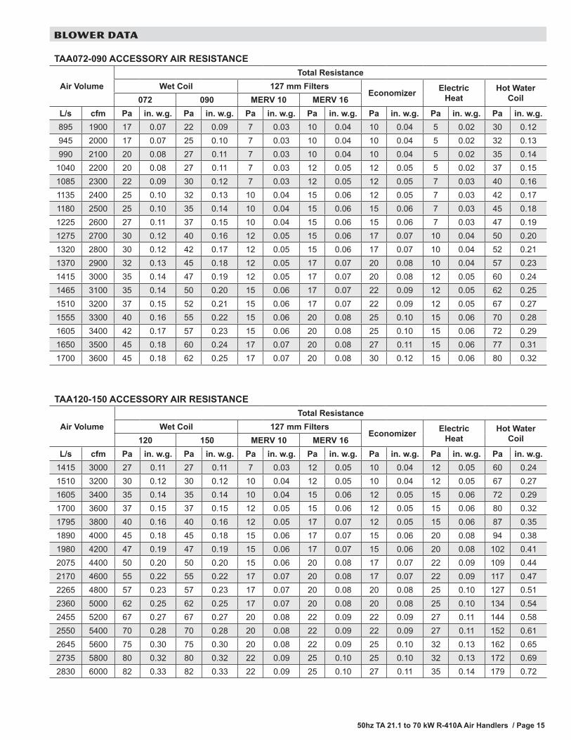
TAA072-090 ACCESSORY AIR RESISTANCE
Air VolumeTotal Resistance
Wet Coil 127 mm FiltersEconomizer Electric
HeatHot Water
Coil072 090 MERV 10 MERV 16L/s cfm Pa in. w.g. Pa in. w.g. Pa in. w.g. Pa in. w.g. Pa in. w.g. Pa in. w.g. Pa in. w.g.895 1900 17 0.07 22 0.09 7 0.03 10 0.04 10 0.04 5 0.02 30 0.12945 2000 17 0.07 25 0.10 7 0.03 10 0.04 10 0.04 5 0.02 32 0.13990 2100 20 0.08 27 0.11 7 0.03 10 0.04 10 0.04 5 0.02 35 0.14
1040 2200 20 0.08 27 0.11 7 0.03 12 0.05 12 0.05 5 0.02 37 0.151085 2300 22 0.09 30 0.12 7 0.03 12 0.05 12 0.05 7 0.03 40 0.161135 2400 25 0.10 32 0.13 10 0.04 15 0.06 12 0.05 7 0.03 42 0.171180 2500 25 0.10 35 0.14 10 0.04 15 0.06 15 0.06 7 0.03 45 0.181225 2600 27 0.11 37 0.15 10 0.04 15 0.06 15 0.06 7 0.03 47 0.191275 2700 30 0.12 40 0.16 12 0.05 15 0.06 17 0.07 10 0.04 50 0.201320 2800 30 0.12 42 0.17 12 0.05 15 0.06 17 0.07 10 0.04 52 0.211370 2900 32 0.13 45 0.18 12 0.05 17 0.07 20 0.08 10 0.04 57 0.231415 3000 35 0.14 47 0.19 12 0.05 17 0.07 20 0.08 12 0.05 60 0.241465 3100 35 0.14 50 0.20 15 0.06 17 0.07 22 0.09 12 0.05 62 0.251510 3200 37 0.15 52 0.21 15 0.06 17 0.07 22 0.09 12 0.05 67 0.271555 3300 40 0.16 55 0.22 15 0.06 20 0.08 25 0.10 15 0.06 70 0.281605 3400 42 0.17 57 0.23 15 0.06 20 0.08 25 0.10 15 0.06 72 0.291650 3500 45 0.18 60 0.24 17 0.07 20 0.08 27 0.11 15 0.06 77 0.311700 3600 45 0.18 62 0.25 17 0.07 20 0.08 30 0.12 15 0.06 80 0.32
TAA120-150 ACCESSORY AIR RESISTANCE
Air VolumeTotal Resistance
Wet Coil 127 mm FiltersEconomizer Electric
HeatHot Water
Coil120 150 MERV 10 MERV 16L/s cfm Pa in. w.g. Pa in. w.g. Pa in. w.g. Pa in. w.g. Pa in. w.g. Pa in. w.g. Pa in. w.g.
1415 3000 27 0.11 27 0.11 7 0.03 12 0.05 10 0.04 12 0.05 60 0.241510 3200 30 0.12 30 0.12 10 0.04 12 0.05 10 0.04 12 0.05 67 0.271605 3400 35 0.14 35 0.14 10 0.04 15 0.06 12 0.05 15 0.06 72 0.291700 3600 37 0.15 37 0.15 12 0.05 15 0.06 12 0.05 15 0.06 80 0.321795 3800 40 0.16 40 0.16 12 0.05 17 0.07 12 0.05 15 0.06 87 0.351890 4000 45 0.18 45 0.18 15 0.06 17 0.07 15 0.06 20 0.08 94 0.381980 4200 47 0.19 47 0.19 15 0.06 17 0.07 15 0.06 20 0.08 102 0.412075 4400 50 0.20 50 0.20 15 0.06 20 0.08 17 0.07 22 0.09 109 0.442170 4600 55 0.22 55 0.22 17 0.07 20 0.08 17 0.07 22 0.09 117 0.472265 4800 57 0.23 57 0.23 17 0.07 20 0.08 20 0.08 25 0.10 127 0.512360 5000 62 0.25 62 0.25 17 0.07 20 0.08 20 0.08 25 0.10 134 0.542455 5200 67 0.27 67 0.27 20 0.08 22 0.09 22 0.09 27 0.11 144 0.582550 5400 70 0.28 70 0.28 20 0.08 22 0.09 22 0.09 27 0.11 152 0.612645 5600 75 0.30 75 0.30 20 0.08 22 0.09 25 0.10 32 0.13 162 0.652735 5800 80 0.32 80 0.32 22 0.09 25 0.10 25 0.10 32 0.13 172 0.692830 6000 82 0.33 82 0.33 22 0.09 25 0.10 27 0.11 35 0.14 179 0.72

50hz TA 21.1 to 70 kW R-410A Air Handlers / Page 16
BLOWER DATA
TAA180-240 ACCESSORY AIR RESISTANCE
Air VolumeTotal Resistance
Wet Coil 127 mm FiltersEconomizer Electric
HeatHot Water
Coil080 240 MERV 10 MERV 16L/s cfm Pa in. w.g. Pa in. w.g. Pa in. w.g. Pa in. w.g. Pa in. w.g. Pa in. w.g. Pa in. w.g.
2125 4500 20 0.08 27 0.11 7 0.03 12 0.05 12 0.05 15 0.06 60 0.242240 4750 22 0.09 30 0.12 10 0.04 12 0.05 15 0.06 20 0.08 65 0.262360 5000 25 0.10 32 0.13 10 0.04 15 0.06 17 0.07 22 0.09 70 0.282475 5250 27 0.11 35 0.14 10 0.04 15 0.06 17 0.07 22 0.09 77 0.312595 5500 27 0.11 37 0.15 12 0.05 15 0.06 20 0.08 27 0.11 82 0.332715 5750 30 0.12 40 0.16 12 0.05 15 0.06 20 0.08 27 0.11 87 0.352830 6000 32 0.13 45 0.18 12 0.05 17 0.07 25 0.10 30 0.12 94 0.382950 6250 35 0.14 47 0.19 15 0.06 17 0.07 27 0.11 35 0.14 99 0.403065 6500 37 0.15 50 0.20 15 0.06 17 0.07 27 0.11 35 0.14 107 0.433185 6750 40 0.16 52 0.21 15 0.06 20 0.08 30 0.12 37 0.15 114 0.463305 7000 42 0.17 55 0.22 17 0.07 20 0.08 30 0.12 37 0.15 119 0.483420 7250 45 0.18 60 0.24 17 0.07 20 0.08 32 0.13 42 0.17 127 0.513540 7500 47 0.19 62 0.25 17 0.07 20 0.08 32 0.13 42 0.17 134 0.543655 7750 47 0.19 65 0.26 20 0.08 22 0.09 35 0.14 45 0.18 142 0.573775 8000 52 0.21 70 0.28 20 0.08 22 0.09 40 0.16 50 0.20 149 0.603895 8250 55 0.22 72 0.29 20 0.08 22 0.09 40 0.16 50 0.20 157 0.634010 8500 57 0.23 77 0.31 22 0.09 25 0.1 42 0.17 52 0.21 164 0.664130 8750 60 0.24 80 0.32 22 0.09 25 0.1 42 0.17 52 0.21 172 0.694245 9000 62 0.25 82 0.33 22 0.09 25 0.1 45 0.18 57 0.23 179 0.724365 9250 65 0.26 87 0.35 25 0.10 27 0.11 47 0.19 60 0.24 189 0.764485 9500 67 0.27 90 0.36 25 0.10 27 0.11 50 0.20 65 0.26 196 0.794600 9750 70 0.28 94 0.38 25 0.10 27 0.11 55 0.22 67 0.27 204 0.824720 10 000 72 0.29 99 0.40 27 0.11 30 0.12 57 0.23 72 0.29 214 0.86
50hz TA 21.1 to 70 kW R-410A Air Handlers / Page 17
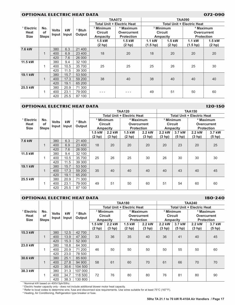
OPTIONAL ELECTRIC HEAT DATA 072-090
1 Electric Heat Size
No. of
Steps
Volts Input
kW Input
2 BtuhOutput
TAA072 TAA090Total Unit + Electric Heat Total Unit + Electric Heat
3 MinimumCircuit
Ampacity
4 Maximum Overcurrent Protection
3 MinimumCircuit
Ampacity
4 MaximumOvercurrent Protection
1.5 kW (2 hp)
1.5 kW (2 hp)
1.1 kW (1.5 hp)
1.5 kW (2 hp)
1.1 kW (1.5 hp)
1.5 kW (2 hp)
7.6 kW1
380 6.3 21 40018 20 18 20 20 20400 6.9 23 400
420 7.6 26 00011.5 kW
1380 9.4 32 100
25 25 25 26 25 30400 10.5 35 700420 11.5 39 300
19.1 kW1
380 15.7 53 50038 40 38 40 40 40400 17.3 59 200
420 19.1 65 20025.5 kW
1380 20.9 71 300
- - - - - - 49 51 50 60400 23.1 79 000420 25.5 87 100
OPTIONAL ELECTRIC HEAT DATA 120-150
1 Electric Heat Size
No. of
Steps
Volts Input
kW Input
2 BtuhOutput
TAA120 TAA150Total Unit + Electric Heat Total Unit + Electric Heat
3 MinimumCircuit
Ampacity
4 Maximum Overcurrent Protection
3 MinimumCircuit
Ampacity
4 Maximum Overcurrent Protection
1.5 kW (2 hp)
2.2 kW (3 hp)
1.5 kW (2 hp)
2.2 kW (3 hp)
2.2 kW (3 hp)
3.7 kW (5 hp)
2.2 kW (3 hp)
3.7 kW (5 hp)
7.6 kW1
380 6.3 21 40018 20 20 20 20 23 20 25400 6.9 23 400
420 7.6 26 00011.5 kW
1380 9.4 32 100
25 26 25 30 26 30 30 30400 10.5 35 700420 11.5 39 300
19.1 kW1
380 15.7 53 50035 40 40 40 40 43 40 45400 17.3 59 200
420 19.1 65 20025.5 kW
1380 20.9 71 300
49 51 50 60 51 54 60 60400 23.1 79 000420 25.5 87 100
OPTIONAL ELECTRIC HEAT DATA 180-240
1 Electric Heat Size
No. of
Steps
Volts Input
kW Input
2 BtuhOutput
TAA180 TAA240Total Unit + Electric Heat Total Unit + Electric Heat
3 MinimumCircuit
Ampacity
4 Maximum Overcurrent Protection
3 MinimumCircuit
Ampacity
4 Maximum Overcurrent Protection
1.5 kW (2 hp)
2.2 kW (3 hp)
1.5 kW (2 hp)
2.2 kW (3 hp)
2.2 kW (3 hp)
3.7 kW (5 hp)
2.2 kW (3 hp)
3.7 kW (5 hp)
15.3 kW1
380 12.5 42 70033 36 35 40 36 41 40 45400 13.9 47 300
420 15.3 52 30023.0 kW
1380 18.8 64 300
46 50 50 50 50 55 50 60400 20.9 71 200420 23.0 78 500
30.6 kW1
380 25.1 85 60058 61 60 70 61 66 70 70400 27.8 94 900
420 30.6 104 50038.3 kW
1380 31.3 107 000
72 76 80 80 76 81 80 90400 34.7 118 500420 38.3 130 800
1 Nominal kW based on 400V/3ph/50hz.2 Electric heater capacity only - does not include additional blower motor heat capacity.3 Refer to local codes to determine wire, fuse and disconnect size requirements. Use wires suitable for at least 75°C (167°F).4 Heating, Air Conditioning, Refrigeration type breaker or fuse.

50hz TA 21.1 to 70 kW R-410A Air Handlers / Page 18
HOT WATER COIL - WATER PRESSURE DROP
Model No.Flow Rate (L/min)
8 15 23 30 38 45 53 61 68 76 83 91 98 106 114 121 129 136Water Pressure Drop (kPa)
TAA072TAA090TAA120TAA150
0.06 0.30 0.60 0.99 1.46 2.00 2.60 3.29 4.04 4.84 5.71 6.67 7.68 8.73 9.86 11.06 12.28 13.60
TAA180TAA240
0.09 0.45 0.90 1.49 2.18 2.99 3.89 4.93 6.04 7.26 8.58 9.98 11.51 13.09 14.80 16.59 18.44 20.41
Model No.Flow Rate (L/min)
144 151 159 167 174 182 189 197 204 212 220 227 235 242 250 257 265Water Pressure Drop (kPa)
TAA072TAA090TAA120TAA150
14.97 16.38 17.87 19.40 20.98 22.63 24.33 26.09 27.89 29.77 31.68 33.66 35.66 37.75 39.87 42.06 44.30
TAA180TAA240
22.45 24.57 26.81 29.11 31.47 33.96 36.50 39.13 41.85 44.66 47.53 50.48 53.50 56.61 59.81 63.07 66.42
SPECIFICATIONS - HOT WATER COILGeneral Data Hot Water Coil Model No. T2HWCL10LM1- T2HWCL10N-1-
Air Handler Model No. TAA072TAA090TAA120TAA150
TAA180TAA240
Water LineConnections
Inlet o.d. - mm (in.) (sweat) 35 (1-3/8) 35 (1-3/8)Outlet o.d. - mm (in.) (sweat) 35 (1-3/8) 35 (1-3/8)
Hot WaterCoil
Net face area - m2 (sq. ft.) 0.56 (6.00) 0.84 (9.00)Tube diameter - mm (in.) 9.5 (3/8) 9.5 (3/8)
Fins per mm (inch) 551 (14) 551 (14)

50hz TA 21.1 to 70 kW R-410A Air Handlers / Page 19
HO
T W
AT
ER
CO
IL C
AP
AC
ITIE
S
Mod
el
No.
Airfl
ow(L
/s)
Ente
ring
Air
Tem
p (°
C)
Ente
ring
Wat
er T
empe
ratu
re (°
C)
8095
100
Wat
er T
empe
ratu
re D
rop
(°C
)11
1722
1117
2211
1722
L/M
kWLA
TL/
MkW
LAT
L/M
kWLA
TL/
MkW
LAT
L/M
kWLA
TL/
MkW
LAT
L/M
kWLA
TL/
MkW
LAT
L/M
kWLA
T
072
905
472
.554
.754
.145
.751
.951
.532
.348
.948
.884
.863
.562
.054
.060
.859
.538
.557
.956
.991
.067
.966
.058
.165
.263
.541
.662
.461
.015
60.8
45.9
57.5
38.0
43.1
55.0
26.5
40.1
52.2
73.0
54.7
65.5
46.1
52.0
63.0
32.6
49.1
60.4
79.2
59.1
69.5
50.2
56.4
67.1
35.7
53.6
64.5
2749
.337
.261
.030
.334
.458
.320
.731
.355
.561
.345
.969
.038
.343
.266
.526
.840
.363
.867
.450
.373
.042
.447
.670
.529
.944
.867
.9
1135
484
.864
.150
.953
.460
.648
.438
.556
.946
.199
.374
.458
.464
.070
.756
.147
.970
.756
.710
6.8
79.1
62.2
70.4
76.1
59.9
49.2
72.5
57.2
1571
.253
.854
.944
.350
.352
.330
.846
.549
.785
.564
.162
.453
.960
.759
.938
.857
.058
.292
.769
.266
.158
.965
.863
.843
.562
.863
.327
57.6
43.5
58.8
35.2
40.0
56.2
24.0
36.3
53.4
71.8
53.8
66.3
44.8
50.4
63.8
31.2
46.9
61.3
79.0
58.9
70.1
49.6
55.6
67.6
34.9
52.3
65.2
1360
496
.172
.648
.360
.368
.545
.842
.464
.243
.311
2.5
84.3
55.4
71.4
80.4
53.0
50.7
76.3
50.5
120.
990
.259
.077
.086
.356
.654
.982
.354
.215
80.6
60.9
52.6
50.0
56.8
50.1
34.6
52.6
47.6
96.9
72.6
59.8
60.9
68.6
57.4
42.9
64.6
54.9
105.
178
.463
.366
.474
.561
.047
.170
.558
.527
65.2
49.3
56.9
39.7
45.2
54.4
26.9
40.8
51.7
81.3
60.9
64.1
50.6
57.0
61.7
35.1
52.9
59.2
89.4
66.7
67.7
56.0
62.8
65.3
39.3
58.8
62.8
090
1135
484
.864
.150
.953
.460
.648
.438
.556
.946
.199
.374
.458
.464
.070
.756
.147
.970
.756
.710
6.8
79.1
62.2
70.4
76.1
59.9
49.2
72.5
57.2
1571
.253
.854
.944
.350
.352
.330
.846
.549
.785
.564
.162
.453
.960
.759
.938
.857
.058
.292
.769
.266
.158
.965
.863
.843
.562
.863
.327
57.6
43.5
58.8
35.2
40.0
56.2
24.0
36.3
53.4
71.8
53.8
66.3
44.8
50.4
63.8
31.2
3.0
61.3
79.0
58.9
70.1
49.6
55.6
67.6
34.9
52.3
65.2
1415
498
.874
.647
.761
.970
.345
.243
.566
.042
.711
5.7
86.7
54.7
73.3
82.6
52.4
52.0
78.4
49.9
124.
392
.758
.279
.088
.655
.956
.484
.553
.515
82.8
62.5
52.1
51.4
58.4
49.7
35.5
53.9
47.1
99.6
74.6
59.2
62.6
70.5
56.8
44.1
66.3
54.3
108.
080
.662
.768
.376
.660
.348
.372
.457
.927
67.0
50.6
56.5
40.8
46.4
54.0
27.6
41.9
51.4
83.5
62.6
63.6
52.0
58.5
61.2
36.1
54.3
58.7
91.9
68.6
67.1
57.5
64.6
64.7
40.3
60.4
62.3
1700
411
1.3
84.1
45.1
69.7
79.1
42.7
48.9
74.1
40.3
130.
597
.851
.782
.593
.049
.458
.688
.147
.014
0.2
104.
655
.089
.099
.952
.763
.495
.150
.415
93.3
70.5
49.9
57.7
65.6
47.5
39.9
60.5
45.0
112.
384
.256
.670
.479
.454
.249
.574
.551
.912
1.9
90.9
59.9
76.9
86.2
57.6
54.4
81.5
55.3
2775
.457
.054
.745
.852
.152
.230
.946
.949
.794
.270
.661
.458
.465
.859
.040
.560
.956
.610
3.7
77.4
64.7
64.8
72.6
62.4
45.3
67.9
60.0
120
1510
410
3.1
77.9
46.8
64.6
73.3
44.3
45.3
68.8
41.9
120.
890
.553
.776
.586
.151
.354
.381
.748
.912
9.8
96.8
57.1
82.5
92.5
54.8
58.8
88.1
52.4
1586
.465
.351
.453
.660
.848
.937
.156
.246
.410
4.0
77.9
58.3
65.3
73.6
55.9
46.0
69.1
53.5
112.
984
.261
.771
.279
.959
.450
.475
.657
.027
69.9
52.8
55.9
42.5
48.3
53.3
28.8
43.6
50.8
87.2
65.4
62.8
54.2
61.1
60.4
37.6
56.6
57.9
96.0
71.6
66.3
60.0
67.3
63.9
42.0
63.0
61.5
1890
411
9.1
90.0
43.6
74.5
84.6
41.2
52.1
79.1
38.8
139.
610
4.7
50.0
88.3
99.5
47.7
62.5
94.1
45.4
150.
111
2.0
53.2
95.2
106.
850
.967
.810
1.6
48.6
1599
.975
.448
.661
.770
.146
.342
.564
.543
.912
0.1
90.0
55.1
75.3
84.8
52.8
52.8
79.5
50.4
130.
497
.358
.282
.392
.356
.058
.187
.053
.727
80.6
60.9
53.6
48.9
55.6
51.2
33.0
50.0
48.8
100.
875
.560
.162
.570
.357
.843
.265
.055
.411
1.0
82.8
63.3
69.2
77.7
61.0
48.3
72.4
58.7
2265
413
3.4
100.
841
.083
.394
.638
.758
.288
.336
.515
6.6
117.
447
.098
.811
1.3
44.8
69.9
105.
242
.616
8.3
125.
650
.010
6.6
119.
647
.875
.811
3.6
45.6
1511
1.8
84.4
46.4
69.0
78.3
44.2
47.5
72.0
41.9
134.
710
0.9
52.4
84.3
94.9
50.3
59.1
88.8
48.0
146.
310
9.2
55.5
92.0
103.
253
.364
.897
.251
.127
90.3
68.2
51.8
54.7
62.0
49.5
36.7
55.7
47.2
112.
984
.657
.869
.878
.655
.748
.272
.653
.412
4.4
92.8
60.9
77.5
86.9
58.7
53.9
80.9
56.5
150
1890
411
9.1
90.0
43.6
74.5
84.6
41.2
52.1
79.1
38.8
139.
610
4.7
50.0
88.3
99.5
47.7
62.5
94.1
45.4
150.
111
2.0
53.2
95.2
106.
850
.967
.810
1.6
48.6
1599
.975
.448
.661
.770
.146
.342
.564
.543
.912
0.1
90.0
55.1
75.3
84.8
52.8
52.8
79.5
50.4
130.
497
.358
.282
.392
.356
.058
.187
.053
.727
80.6
60.9
53.6
48.9
55.6
51.2
33.0
50.0
48.8
100.
875
.560
.162
.570
.357
.843
.265
.055
.411
1.0
82.8
63.3
69.2
77.7
61.0
48.3
72.4
58.7
2360
413
6.7
103.
340
.485
.496
.938
.259
.690
.435
.916
0.6
120.
346
.310
1.3
114.
044
.171
.610
7.8
42.0
172.
612
8.7
49.3
109.
312
2.6
47.1
77.6
116.
445
.015
114.
686
.645
.970
.780
.243
.748
.673
.741
.413
8.1
103.
551
.986
.397
.349
.760
.591
.147
.515
0.0
111.
954
.894
.310
5.8
52.7
66.4
99.6
50.5
2792
.569
.951
.456
.063
.549
.237
.657
.046
.811
5.8
86.8
57.4
71.6
80.6
55.2
49.4
74.3
53.0
127.
695
.260
.379
.489
.058
.255
.382
.956
.0
2830
415
2.5
115.
237
.995
.110
7.9
35.7
66.2
100.
533
.617
9.1
134.
243
.411
2.8
127.
141
.379
.711
9.9
39.2
192.
614
3.7
46.1
121.
813
6.6
44.1
86.4
129.
542
.015
127.
896
.543
.878
.689
.241
.653
.981
.839
.515
4.0
115.
449
.396
.210
8.4
47.2
67.2
101.
245
.116
7.4
124.
952
.110
5.1
117.
950
.073
.911
0.8
47.9
2710
3.1
77.9
49.6
62.2
70.6
47.5
41.6
63.2
45.3
129.
196
.755
.279
.689
.753
.154
.882
.551
.014
2.3
106.
158
.088
.499
.155
.961
.492
.153
.8LA
T =
Leav
ing
Air
Tem
pera
ture

50hz TA 21.1 to 70 kW R-410A Air Handlers / Page 20
HO
T W
AT
ER
CO
IL C
AP
AC
ITIE
S
Mod
el
No.
Airfl
ow
(L/s
)
Ente
ring
Air
Tem
p (°
C)
Ente
ring
Wat
er T
empe
ratu
re (°
C)
8095
100
Wat
er T
empe
ratu
re D
rop
(°C
)11
2217
1122
1711
2217
L/M
kWLA
TL/
MkW
LAT
L/M
kWLA
TL/
MkW
LAT
L/M
kWLA
TL/
MkW
LAT
L/M
kWLA
TL/
MkW
LAT
L/M
kWLA
T
180
2265
415
7.3
118.
947
.599
.411
2.9
45.4
70.4
106.
843
.218
3.8
137.
754
.411
7.2
132.
052
.384
.812
5.5
50.7
197.
314
7.2
57.8
126.
214
1.5
55.7
90.8
134.
953
.615
132.
299
.952
.182
.794
.049
.957
.987
.847
.715
8.5
118.
859
.010
0.4
113.
056
.971
.210
7.1
54.7
171.
712
8.1
62.4
109.
212
2.5
60.3
78.1
116.
458
.427
107.
381
.056
.566
.175
.154
.345
.368
.852
.013
3.2
99.8
63.5
83.5
94.1
61.4
58.6
88.1
59.1
146.
410
9.3
66.9
92.4
103.
664
.865
.297
.762
.7
2830
418
1.8
137.
444
.311
4.7
130.
342
.281
.112
3.0
40.1
212.
615
9.3
50.6
135.
315
2.4
48.7
96.6
145.
446
.622
8.2
170.
353
.814
5.7
163.
451
.810
4.4
156.
549
.815
152.
911
5.5
49.3
95.4
108.
347
.266
.610
1.0
45.1
183.
313
7.3
55.7
115.
813
0.5
53.7
82.0
123.
451
.619
8.7
148.
258
.912
6.1
141.
556
.989
.713
4.5
54.9
2712
3.9
93.6
54.3
76.2
86.5
52.2
52.1
79.0
50.0
154.
111
5.5
60.7
96.4
108.
658
.767
.410
1.5
56.6
169.
412
6.4
63.9
106.
611
9.5
61.9
75.1
112.
559
.9
3400
420
3.8
154.
041
.712
8.4
145.
839
.790
.613
7.4
37.7
238.
517
8.7
47.6
151.
517
0.7
45.7
108.
016
2.6
43.7
255.
919
0.9
50.6
163.
318
3.1
48.7
116.
917
5.1
46.8
1517
1.2
129.
447
.110
6.8
121.
245
.174
.311
2.8
43.0
205.
515
4.0
53.1
129.
714
6.0
51.1
91.6
137.
949
.222
2.9
166.
356
.114
1.2
158.
454
.210
0.4
150.
452
.227
138.
810
4.9
52.4
85.1
96.7
50.4
58.1
88.1
48.3
172.
712
9.5
58.5
107.
912
1.5
56.5
75.3
113.
354
.519
0.0
141.
761
.511
9.3
133.
859
.684
.012
5.8
57.6
240
3020
418
9.3
143.
143
.311
9.4
135.
641
.384
.412
8.0
39.2
221.
516
6.0
49.6
140.
915
8.7
47.6
100.
515
1.4
45.6
237.
817
7.4
52.7
151.
817
0.2
50.7
108.
716
2.9
48.7
1515
9.0
120.
248
.599
.411
2.8
46.5
69.3
105.
144
.419
0.9
143.
154
.812
0.6
135.
952
.885
.312
8.4
50.8
207.
015
4.5
57.9
131.
414
7.3
55.9
93.4
140.
053
.927
129.
097
.553
.679
.390
.051
.654
.282
.149
.416
0.5
120.
359
.910
0.4
113.
157
.970
.110
5.5
55.8
176.
513
1.7
63.1
111.
012
4.5
61.1
78.2
117.
159
.0
3775
421
7.4
164.
240
.213
6.8
155.
338
.296
.414
6.3
36.3
254.
319
0.6
45.9
161.
518
2.0
44.0
115.
117
3.2
42.1
273.
120
3.8
48.8
174.
119
5.2
46.9
124.
518
6.6
45.0
1518
2.6
137.
945
.811
3.6
129.
043
.979
.112
0.0
41.9
219.
216
4.3
51.6
138.
215
5.7
49.7
97.6
146.
847
.823
7.8
177.
454
.515
0.5
168.
952
.610
6.9
160.
250
.727
148.
011
1.8
51.4
90.6
102.
949
.461
.793
.747
.418
4.2
138.
057
.211
4.9
129.
455
.380
.112
0.6
53.3
202.
615
1.2
60.1
127.
214
2.7
58.2
89.3
133.
956
.3
4530
424
2.1
182.
937
.615
2.2
172.
835
.810
7.1
162.
533
.927
9.8
211.
042
.417
9.8
202.
541
.212
7.9
192.
539
.329
5.1
223.
244
.419
3.7
217.
343
.813
8.4
207.
542
.115
203.
415
3.6
43.6
126.
414
3.5
41.8
87.8
133.
139
.924
4.2
183.
049
.015
3.8
173.
247
.210
8.4
163.
245
.426
5.0
197.
751
.716
7.6
188.
049
.911
8.8
178.
148
.127
164.
812
4.5
49.6
100.
711
4.3
47.7
68.4
103.
845
.820
5.2
153.
855
.012
7.8
143.
953
.289
.013
3.9
51.3
225.
816
8.4
57.7
141.
515
8.7
55.9
99.3
148.
854
.1LA
T =
Leav
ing
Air
Tem
pera
ture

50hz TA 21.1 to 70 kW R-410A Air Handlers / Page 21
WEIGHT DATA
Model NumberNet Shipping
kg lbs. kg lbs.072 150 330 172 380090 159 350 181 400120 197 435 225 495150 206 455 234 515180 680 308 760 345240 720 327 800 363
OPTIONS / ACCESSORIESNet Shipping
kg lbs. kg lbs.
ELECTRIC HEAT
072-150 6.9 kW 29 65 34 7510.4 kW 29 65 34 7517.4 kW 29 65 34 7524.3 kW 29 65 34 75
180-240 15.3 kW 45 100 54 12023.0 kW 45 100 54 12030.6 kW 45 100 54 12038.3 kW 45 100 54 120
ECONOMIZER
T2ECON31L-1- 32 71 75 165T2ECON31M-1- 52 114 120 265T2ECON31N-1- 73 160 168 370
127 MM FILTER MOUNTING KIT
T2FLTR70L-1- 3 7 5 10T2FLTR70M-1- 5 10 6 14T2FLTR70N-1- 7 15 9 20
HOT WATER COIL
T2HWCL10LM1- 29 65 36 80T2HWCL10N-1- 36 80 45 100
RETURN AIR GRILLE
T2GARD30L-1 2 4 9 20T2GARD30M-1 2 5 14 30T2GARD30N-1 3 6 16 35
UVC LIGHT KITS
T2UVCL10LM1Y 8 17 9 20T2UVCL10N-1Y 10 23 12 26
50hz TA 21.1 to 70 kW R-410A Air Handlers / Page 22
UNIT CLEARANCES - MM (INCHES)
SUPPLY AIROPENING
2 SeeNOTES
CONTROLBOX
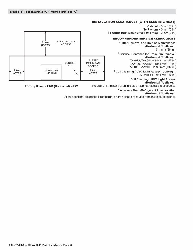
INSTALLATION CLEARANCES (WITH ELECTRIC HEAT)Cabinet − 0 mm (0 in.)
To Plenum − 0 mm (0 in.)To Outlet Duct within 3 feet (914 mm) − 0 mm (0 in.)
RECOMMENDED SERVICE CLEARANCES1 Filter Removal and Routine Maintenance
(Horizontal / Upflow):914 mm (36 in.)
1 Service Clearance for Drain Pan Removal(Horizontal / Upflow):
TAA072, TAA090 − 1448 mm (57 in.) TAA120, TAA150 − 1854 mm (73 in.)TAA180, TAA240 − 2590 mm (102 in.)
2 Coil Cleaning / UVC Light Access (Upflow) :All models − 914 mm (36 in.)
3 Coil Cleaning / UVC Light Access(Horizontal / Upflow):
Provide 914 mm (36 in.) on this side if top/rear access is obstructed3 Alternate Drain/Refrigerant Line Location
(Horizontal / Upflow):Allow additional clearance if refrigerant or drain lines are routed from this side of cabinet.
1 SeeNOTES
FILTER/DRAIN PAN
ACCESS
COIL / UVC LIGHTACCESS
TOP (Upflow) or END (Horizontal) VIEW
3 SeeNOTES

50hz TA 21.1 to 70 kW R-410A Air Handlers / Page 23
DIMENSIONS - MM (INCHES) - TAA072 AND TAA090
SUPPLY END VIEW
INLET VIEW DRIVE END VIEW
SUCTION (VAPOR) LINEINLETS / KNOCKOUTS (2)LIQUID LINE INLETS / KNOCKOUTS (2)
AIR FILTERS
INDOORCOIL
BLOWER
CONTROLBOX
CONDENSATEDRAIN (Upflow)
SIDE RETURNAIR OPENING
SUPPLY AIROPENING
AIR FLOW
UPFLOW POSITION SHOWN
AIR FLOW
CONTROL BOX(Alternate Location)
CONDENSATEDRAIN
(Horizontal)
AIR
FLO
W
CONTROLBOX
CONTROL BOX(Alternate Location)
SUPPLY AIR FLANGES(Furnished with Unit,
Field Installed)
RETURN AIR FLANGES(Furnished with Unit,
Field Installed)RETURN AIR FLANGES
(Furnished with Unit,Field Installed)
NOTE:072 models only use one Suction and LiquidLine. Cabinet has knockouts for two. Eitheropening may be used.
RETURN AIR OPENING(Bottom or Horizontal Applications)
AA
BB CC
DD
FF
EECENTER OF
GRAVITY
RETURN AIROPENING
(Bottom or Horizontal Applications)
POWERENTRYHOLES749
(29-1/2) 473(18-5/8)
35(1-3/8)
1302(51-1/4)
1302(51-1/4)
51(2)
762(30)
267(10-3/4)
524(20-5/8)
654(25-3/4)
429(16-7/8)25 (1)
TYP.
762 (30)
1 (25)TYP.
1391(54-3/4)
51(2)
667(26-1/4)
749(29-1/2)
76(3)
76(3)
48(1-7/8)
302(11-7/8)
356(14)
419(16-1/2)
473(18-5/8)
473(18-5/8)
524(20-5/8)41
(1-5/8)
524(20-5/8)
35(1-3/8)
CORNER WEIGHTS CENTER OF GRAVITYAA BB CC DD EE FF
kg lbs. kg lbs. kg lbs. kg lbs. mm in. mm in.40 88 40 88 40 88 40 88 648 25-1/2 648 25-1/2

50hz TA 21.1 to 70 kW R-410A Air Handlers / Page 24
DIMENSIONS - MM (INCHES) - TAA0120 AND TAA150
SUCTION (VAPOR) LINEINLETS/KNOCKOUTS (2)
LIQUID LINE INLETS/KNOCKOUTS (2)
AIR FILTERS
INDOORCOIL
BLOWER
CONTROLBOX
AIR FLOW
AIR FLOW
CONDENSATEDRAIN
(Horizontal)
AIR
FLO
W
SUPPLY END VIEW
WEIV DNE EVIRDWEIV TELNI
SUPPLY AIROPENING
CONTROLBOX
CONDENSATEDRAIN (Upflow)
CONTROL BOX(Alternate Location)
SUPPLY AIRFLANGES (Furnished
with Unit, FieldInstalled)
RETURN AIR FLANGES(Furnished with Unit, Field Installed)
RETURN AIR FLANGES(Furnished with Unit,
Field Installed)
CONTROL BOX(Alternate Location)
SIDE RETURNAIR OPENING
UPFLOW POSITION SHOWN
POWERENTRYHOLES
FF
EECENTER OF
GRAVITY
AA
BB CC
DD
RETURN AIR OPENING(Bottom or Horizontal Applications)
RETURN AIROPENING
(Bottom or Horizontal Applications)
749(29-1/2)
524(20-5/8)
1708(67-1/4)
283(11-1/8)
1143(45)
51(2)
1708(67-1/4)
654(25-3/4)
429(24-7/8)
25 (1)TYP.
473(18-5/8)
35(1-3/8)
1143 (45)
25 (1)TYP.
1391(54-3/4)
51(2)
667(26-1/4)
749(29-1/2)
76(3)
76(3)
48(1-7/8)
302(11-7/8)
356(14)
419(16-1/2)
473(18-5/8)
473(18-5/8)
41(1-5/8)
524(20-5/8)
524(20-5/8)
35(1-3/8)
CORNER WEIGHTS CENTER OF GRAVITYAA BB CC DD EE FF
kg lbs. kg lbs. kg lbs. kg lbs. mm in. mm in.57 126 46 101 46 101 57 126 851 33-1/2 622 24-1/2

50hz TA 21.1 to 70 kW R-410A Air Handlers / Page 25
DIMENSIONS - MM (INCHES) - TAA0180 AND TAA240
SUPPLY END VIEW
INLET VIEW DRIVE END VIEW
SUPPLY AIROPENING
SUCTION (VAPOR) LINEINLETS/KNOCKOUTS (2)LIQUID LINE INLETS/KNOCKOUTS (2)
AIR FILTERS
INDOORCOIL
BLOWER
CONTROLBOX
AIR FLOW
AIR FLOW
CONDENSATEDRAIN
(Horizontal)A
IR F
LOW
CONTROLBOX
CONTROL BOX(Alternate Location)
SUPPLY AIRFLANGES
(Furnished withUnit, FieldInstalled) CONTROL BOX
(Alternate Location)
CONDENSATEDRAIN (Upflow)
RETURN AIR FLANGES(Furnished with Unit, Field Installed)
RETURN AIR FLANGES(Furnished with Unit,
Field Installed)
SIDE RETURNAIR OPENING
UPFLOW POSITION SHOWN
POWERENTRYHOLES
RETURN AIROPENING
(Bottom or Horizontal Applications)
RETURN AIR OPENING(Bottom or Horizontal Applications)
FF
EECENTER OF
GRAVITY
AA
BB CC
DD
749(29-1/2)
524(20-5/8)
51(2)
2445(96-1/4)
2445(96-1/4)
1505(59-1/4)
1311(51-5/8)
699(27-1/2)25 (1)
TYP.
473(18-5/8)
35(1-3/8)
25 (1)TYP.
1505 (59-1/4)
470(18-1/2)
1391(54-3/4)
51(2)
667(26-1/4)
749(29-1/2)
76(3)
76(3)
48(1-7/8)
302(11-7/8)
356(14)
419(16-1/2)
473(18-5/8)
473(18-5/8)
41(1-5/8)
524(20-5/8)
524(20-5/8)
35(1-3/8)
CORNER WEIGHTS CENTER OF GRAVITYAA BB CC DD EE FF
kg lbs. kg lbs. kg lbs. kg lbs. mm in. mm in.50 110 45 99 53 116 59 130 1321 52 654 25-3/4
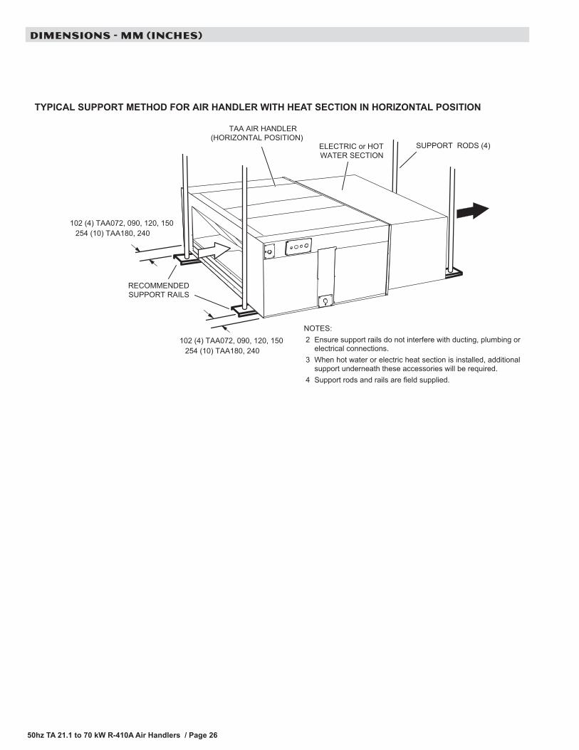
50hz TA 21.1 to 70 kW R-410A Air Handlers / Page 26
DIMENSIONS - MM (INCHES)
TYPICAL SUPPORT METHOD FOR AIR HANDLER WITH HEAT SECTION IN HORIZONTAL POSITION
ELECTRIC or HOTWATER SECTION
TAA AIR HANDLER(HORIZONTAL POSITION)
102 (4) TAA072, 090, 120, 150254 (10) TAA180, 240
SUPPORT RODS (4)
RECOMMENDEDSUPPORT RAILS
NOTES:2 Ensure support rails do not interfere with ducting, plumbing or
electrical connections.3 When hot water or electric heat section is installed, additional
support underneath these accessories will be required.4 Support rods and rails are field supplied.
102 (4) TAA072, 090, 120, 150254 (10) TAA180, 240

50hz TA 21.1 to 70 kW R-410A Air Handlers / Page 27
DIMENSIONS - MM (INCHES) - ELECTRIC HEAT
FRONT VIEW SIDE VIEW
TOP VIEW
1 467(18-3/8)
27-1/4(692)
381(15)
25 (1)
25 (1)
17(11/16)
AIR FLOW
1 NOTE-Opening same top and bottom.
17(11/16)
17(11/16)
1 467(18-3/8)
FIELD POWER ENTRY
POWER AND CONTROL WIRINGTO AIR HANDLER
A
1 B
CD1 B
D
C
Air Handler Usage
A B C D
mm in. mm in. mm in. mm in.
TAA072 Thru TAA150 689 27-1/8 648 25-1/2 21 13/16 21 13/16
TAA180 Thru TAA240 1441 56-3/4 1302 51-1/4 38 1-1/2 102 4

50hz TA 21.1 to 70 kW R-410A Air Handlers / Page 28
DIMENSIONS - MM (INCHES) - HOT WATER COIL
FRONT VIEW SIDE VIEW
TOP VIEW
28-1/2(724)
14(356)
2-7/8 (73)
2-1/8 (54)
2-1/2(64)
WATER OUTLET
WATER INLET
1 24(610)
2-1/4 (57)
2-1/4(57)
1-5/8(41)
AIR FLOW
1 A
B
1 NOTE - Openings same size top and bottom.
Air Handler Usage
A B
mm in. mm in.
TAA072 Thru TAA150 914 36 1219 48
TAA180 Thru TAA240 1372 54 1676 66

50hz TA 21.1 to 70 kW R-410A Air Handlers / Page 29
DIMENSIONS - MM (INCHES) - ECONOMIZER
.
686(27)
521(20-1/2)
622(24-1/2)
521(20-1/2)
OUTDOOR
22(7/8)
RETURN
SIDE VIEW END VIEW
TOP VIEW19
(3/4)19
(3/4)
76 (3)
A
B
CB
19(3/4)
19(3/4)
C
C C
NOTE- Economizer section may be rotated180° for bottom return air connection.
AIR
AIR
SUPPLY
AIR
Model No. (Air Handler Usage)
A B Cmm in. mm in. mm in.
T2ECON31L-1- (072-090) 813 32 762 30 25 1
T2ECON31M-1- (120-150) 1308 51-1/2 1143 45 83 3-1/4
T2ECON31N-1- (180-240) 72 1829 60 1524 6 152

50hz TA 21.1 to 70 kW R-410A Air Handlers / Page 30
ACCESSORY DIMENSIONS - MM (INCHES)
AIR HANDLER WITH OPTIONAL ELECTRIC HEAT/HOT WATER COIL AND ECONOMIZER
AIR
AIR
1 ECONOMIZERDAMPERSECTION
OUTDOOR
RETURN
16 (406)Electric Heat
14 (356)Hot Water
54-3/4(1391)
27(686)
AIR
AIR
1 ECONOMIZERDAMPERSECTION
1 HEATSECTION
1 AIRHANDLERSECTION
70-3/4 (1797)Electric Heat68-3/4 (1746)
Hot Water
OUTDOOR
RETURN
NOTE -Electric Heat flange installsinside supply air flange on airhandler unitHot Water Coil installs flushon air handler unitMounting holes are furnishedfor alignment.
AIRSUPPLYUPFLOW
HORIZONTAL
54-3/4(1391)
27(686)
AIR
AIR
1 ECONOMIZERDAMPERSECTION
1 HEATSECTION
1 AIRHANDLER
97-3/4 (2483) Electric Heat95-3/4 (2432) Hot Water
OUTDOOR
RETURN
AIR
AIR
1 ECONOMIZERDAMPERSECTION
OUTDOOR
RETURN
1 ALTERNATEECONOMIZER
LOCATION
1 ALTERNATEECONOMIZER
LOCATION
1 NOTE -Economizer, Electric Heat/Hot Water Coil and Air Handlermust be properly supported.16 (406)
Electric Heat14 (356)
Hot Water
NOTE -Electric Heat flange installsinside supply air flange on airhandler unitHot Water Coil installs flushon air handler unitMounting holes are furnishedfor alignment.
1 NOTE -Economizer, Electric Heat/Hot Water Coil and Air Handlermust be properly supported.


NOTE - Due to Lennox’ ongoing commitment to quality, Specifications, Ratings and Dimensions subject to change without notice and without incurring liability. Improper installation, adjustment, alteration, service or maintenance can cause property damage or personal injury. Installation and service must be performed by a qualified installer and servicing agency. ©2010 Lennox Industries, Inc.
Visit us at www.lennox.com
For the latest technical information, www.lennoxcommercial.com
Contact us at 1-800-4-LENNOX
REVISIONS
Sections Description of Change
Document Updated to new publishing software. No changes to data.