Air Filters Compressed Balston Coalescing … · 3 Parker Hannifin Corporation Filtration and...
33
Compressed Air Filters Compressed Air Filters Balston Microfiber ® Filter Assemblies Balston Coalescing Compressed Air Filters Balston Coalescing Compressed Air Filters protect your equipment and delicate instruments from the dirt, water, and oil usually found in compressed air. Balston Coalesc- ing Filters remove these contaminants at a very high effi- ciency up to 99.99% for 0.01 micron particles and droplets. Liquid releases from the filter cartridge to an automatic drain as rapidly as it enters the filter. This allows a Balston Coalescing Filter to continue removing liquids for an unlim- ited time without loss of efficiency or flow capacity. Select 1/4” to 2” line filters come with a lifetime (20 year) warranty which guarantees the product against defects and other failures. Remove 99.99% of 0.01 micron particles of oil, water, and dirt from compressed air and other gases Continuously trap and drain liquids Service flow ranges from a few SCFM to 40,000 SCFM Remove trace oil vapor with adsorbent cartridges Lifetime warranty (20 year) with select 1/4” to 2” line filters Compressed Air Systems Pnuematic Tools and Cylinders Instrumentation and Automated Pnuematic Controls
Transcript of Air Filters Compressed Balston Coalescing … · 3 Parker Hannifin Corporation Filtration and...

1 Parker Hannifin CorporationFiltration and Separation DivisionHaverhill, MA 1-800-343-4048 www.parker.com/balston
Compressed Air FiltersCom
pressedAir Filters
Balston Microfiber® Filter Assemblies
Balston Coalescing Compressed Air Filters
Balston Coalescing Compressed Air Filters protect your equipment and delicate instruments from the dirt, water, and oil usually found in compressed air. Balston Coalesc-ing Filters remove these contaminants at a very high effi-ciency up to 99.99% for 0.01 micron particles and droplets. Liquid releases from the filter cartridge to an automatic drain as rapidly as it enters the filter. This allows a Balston Coalescing Filter to continue removing liquids for an unlim-ited time without loss of efficiency or flow capacity. Select 1/4” to 2” line filters come with a lifetime (20 year) warranty which guarantees the product against defects and other failures.
Remove 99.99% of 0.01 micron particles of oil, water, and dirt from compressed air and other gases
Continuously trap and drain liquids
Service flow ranges from a few SCFM to 40,000 SCFM
Remove trace oil vapor with adsorbent cartridges
Lifetime warranty (20 year) with select 1/4” to 2” line filters
Compressed Air Systems Pnuematic Tools and CylindersInstrumentation and Automated Pnuematic Controls
Compressed Air Filters
2 Parker Hannifin CorporationFiltration and Separation DivisionHaverhill, MA 1-800-343-4048 www.parker.com/balston
Com
pres
sed
Air F
ilter
sFilter Cartridge and Housing Selection
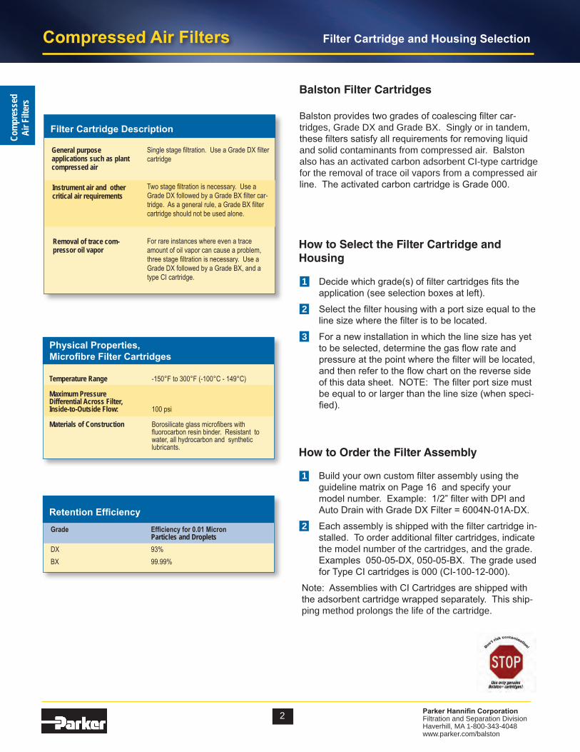
Balston Filter Cartridges
Balston provides two grades of coalescing filter car-tridges, Grade DX and Grade BX. Singly or in tandem, these filters satisfy all requirements for removing liquid and solid contaminants from compressed air. Balston also has an activated carbon adsorbent CI-type cartridge for the removal of trace oil vapors from a compressed air line. The activated carbon cartridge is Grade 000.
How to Select the Filter Cartridge and Housing
Single stage filtration. Use a Grade DX filter cartridge
Two stage filtration is necessary. Use a Grade DX followed by a Grade BX filter car-tridge. As a general rule, a Grade BX filter cartridge should not be used alone.
For rare instances where even a trace amount of oil vapor can cause a problem, three stage filtration is necessary. Use a Grade DX followed by a Grade BX, and a type CI cartridge.
General purpose applications such as plant compressed air
Filter Cartridge Description
Removal of trace com-pressor oil vapor
Instrument air and other critical air requirements
How to Order the Filter Assembly
Temperature Range -150°F to 300°F (-100°C - 149°C)
Maximum PressureDifferential Across Filter,Inside-to-Outside Flow: 100 psi
Materials of Construction Borosilicate glass microfibers with fluorocarbon resin binder. Resistant to water, all hydrocarbon and synthetic lubricants.
Physical Properties, Microfibre Filter Cartridges
Retention Efficiency
Grade Efficiencyfor0.01Micron Particles and DropletsDX 93%BX 99.99%
1 Decide which grade(s) of filter cartridges fits the application (see selection boxes at left).
2 Select the filter housing with a port size equal to the line size where the filter is to be located.
3 For a new installation in which the line size has yet to be selected, determine the gas flow rate and pressure at the point where the filter will be located, and then refer to the flow chart on the reverse side of this data sheet. NOTE: The filter port size must be equal to or larger than the line size (when speci-fied).
1 Build your own custom filter assembly using the guideline matrix on Page 16 and specify your model number. Example: 1/2” filter with DPI and Auto Drain with Grade DX Filter = 6004N-01A-DX.
2 Each assembly is shipped with the filter cartridge in-stalled. To order additional filter cartridges, indicate the model number of the cartridges, and the grade. Examples 050-05-DX, 050-05-BX. The grade used for Type CI cartridges is 000 (CI-100-12-000).
Note: Assemblies with CI Cartridges are shipped with the adsorbent cartridge wrapped separately. This ship-ping method prolongs the life of the cartridge.
3 Parker Hannifin CorporationFiltration and Separation DivisionHaverhill, MA 1-800-343-4048 www.parker.com/balston
Compressed Air FiltersCom
pressedAir Filters
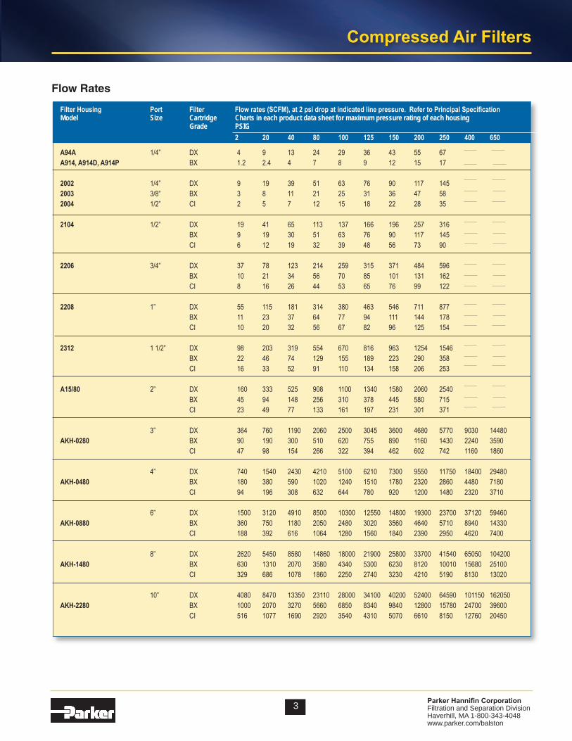
Flow Rates
FilterHousing Port Filter Flowrates(SCFM),at2psidropatindicatedlinepressure.RefertoPrincipalSpecificationModel Size Cartridge Charts in each product data sheet for maximum pressure rating of each housing Grade PSIG 2 20 40 80 100 125 150 200 250 400 650
A94A 1/4” DX 4 9 13 24 29 36 43 55 67A914,A914D,A914P BX 1.2 2.4 4 7 8 9 12 15 17
2002 1/4” DX 9 19 39 51 63 76 90 117 1452003 3/8” BX 3 8 11 21 25 31 36 47 582004 1/2” CI 2 5 7 12 15 18 22 28 35
2104 1/2” DX 19 41 65 113 137 166 196 257 316 BX 9 19 30 51 63 76 90 117 145 CI 6 12 19 32 39 48 56 73 90
2206 3/4” DX 37 78 123 214 259 315 371 484 596 BX 10 21 34 56 70 85 101 131 162 CI 8 16 26 44 53 65 76 99 122
2208 1” DX 55 115 181 314 380 463 546 711 877 BX 11 23 37 64 77 94 111 144 178 CI 10 20 32 56 67 82 96 125 154
2312 1 1/2” DX 98 203 319 554 670 816 963 1254 1546 BX 22 46 74 129 155 189 223 290 358 CI 16 33 52 91 110 134 158 206 253
A15/80 2” DX 160 333 525 908 1100 1340 1580 2060 2540 BX 45 94 148 256 310 378 445 580 715 CI 23 49 77 133 161 197 231 301 371
3” DX 364 760 1190 2060 2500 3045 3600 4680 5770 9030 14480AKH-0280 BX 90 190 300 510 620 755 890 1160 1430 2240 3590 CI 47 98 154 266 322 394 462 602 742 1160 1860
4” DX 740 1540 2430 4210 5100 6210 7300 9550 11750 18400 29480AKH-0480 BX 180 380 590 1020 1240 1510 1780 2320 2860 4480 7180 CI 94 196 308 632 644 780 920 1200 1480 2320 3710
6” DX 1500 3120 4910 8500 10300 12550 14800 19300 23700 37120 59460AKH-0880 BX 360 750 1180 2050 2480 3020 3560 4640 5710 8940 14330 CI 188 392 616 1064 1280 1560 1840 2390 2950 4620 7400
8” DX 2620 5450 8580 14860 18000 21900 25800 33700 41540 65050 104200AKH-1480 BX 630 1310 2070 3580 4340 5300 6230 8120 10010 15680 25100 CI 329 686 1078 1860 2250 2740 3230 4210 5190 8130 13020
10” DX 4080 8470 13350 23110 28000 34100 40200 52400 64590 101150 162050AKH-2280 BX 1000 2070 3270 5660 6850 8340 9840 12800 15780 24700 39600 CI 516 1077 1690 2920 3540 4310 5070 6610 8150 12760 20450
Compressed Air Filters
4 Parker Hannifin CorporationFiltration and Separation DivisionHaverhill, MA 1-800-343-4048 www.parker.com/balston
Com
pres
sed
Air F
ilter
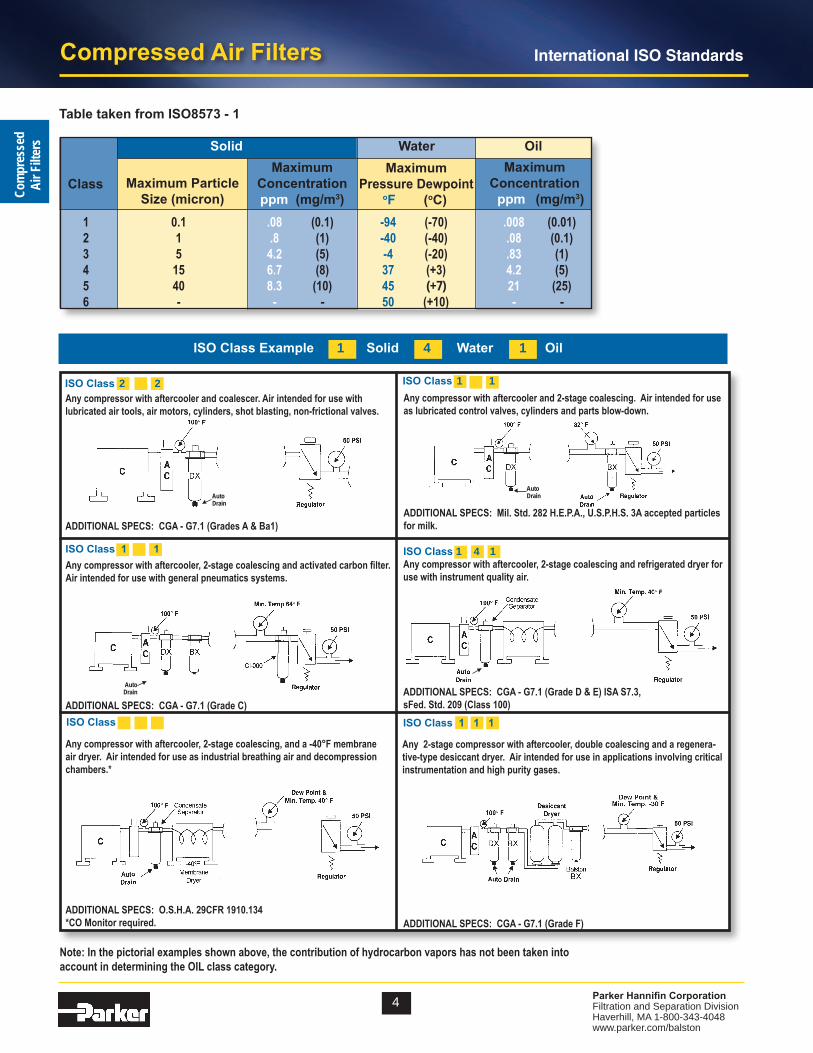
sInternational ISO Standards
ISO Class 1 4 1Anycompressorwithaftercooler,2-stagecoalescingandrefrigerateddryerforusewithinstrumentqualityair.
ADDITIONALSPECS:CGA-G7.1(GradeD&E)ISAS7.3,sFed.Std.209(Class100)
Anycompressorwithaftercooler,2-stagecoalescingandactivatedcarbonfilter.Airintendedforusewithgeneralpneumaticssystems.
ADDITIONALSPECS:CGA-G7.1(GradeC)
Anycompressorwithaftercooler,2-stagecoalescing,anda-40°Fmembraneairdryer.Airintendedforuseasindustrialbreathingairanddecompressionchambers.*
ADDITIONALSPECS:O.S.H.A.29CFR1910.134*COMonitorrequired.
Table taken from ISO8573 - 1
ISO Class 1 1
ISO Class 1 2 1
Anycompressorwithaftercoolerandcoalescer.Airintendedforusewithlubricatedairtools,airmotors,cylinders,shotblasting,non-frictionalvalves.
ADDITIONALSPECS:CGA-G7.1(GradesA&Ba1)
ADDITIONALSPECS:CGA-G7.1(GradeF)
Any2-stagecompressorwithaftercooler,doublecoalescingandaregenera-tive-typedesiccantdryer.Airintendedforuseinapplicationsinvolvingcriticalinstrumentationandhighpuritygases.
ISO Class Example 1 Solid 4 Water 1 Oil
ISO Class 1 1
ISO Class 1 1 1
Anycompressorwithaftercoolerand2-stagecoalescing.Airintendedforuseaslubricatedcontrolvalves,cylindersandpartsblow-down.
ADDITIONALSPECS:Mil.Std.282H.E.P.A.,U.S.P.H.S.3Aacceptedparticlesformilk.
AutoDrain▼
▼
AutoDrain
▼AutoDrain
▼
ISO Class 2 2
Note:Inthepictorialexamplesshownabove,thecontributionofhydrocarbonvaporshasnotbeentakeninto accountindeterminingtheOILclasscategory.
Maximum Particle Size (micron)
MaximumConcentrationppm (mg/m3)
Maximum Pressure Dewpoint oF (oC)
1 0.1 .08 (0.1) -94 (-70) .008 (0.01) 2 1 .8 (1) -40 (-40) .08 (0.1) 3 5 4.2 (5) -4 (-20) .83 (1) 4 15 6.7 (8) 37 (+3) 4.2 (5) 5 40 8.3 (10) 45 (+7) 21 (25) 6 - - - 50 (+10) - -
Solid Water Oil
ClassMaximum
Concentration ppm (mg/m3)

5 Parker Hannifin CorporationFiltration and Separation DivisionHaverhill, MA 1-800-343-4048 www.parker.com/balston
Compressed Air FiltersCom
pressedAir Filters
Some compressor installations do not have an after-cooler (this is an undesirable situation). Air saturated with water vapor leaves a compressor at 240°F to 400°F (116°C to 204°C). Without an aftercooler, the air cools close to room temperature in the distribution lines and water condenses throughout the air distribution system. About two-thirds of the total water content of the air
Compressor Filter Specifications
MicrofibreFilterCartridge Grade DX
Filter Housing Determine filter size from flow chart on page 3, but port size must be equal to or larger than the line size
Automatic Drain Recommended
Differential Pressure Indicator Recommended
Recommendations for Typical Filter Installations
will be condensed when the air has cooled to 100°F (38°C). A filter located just before the main air line branches into smaller distribution lines will remove most of the water load from the system. The filter requirements for the main line are described above; they are the same as for a system with an aftercooler. However, since the air will continue to cool in the dis-tribution system, additional filters located at end- use points will be required to remove water condensed downstream from the main line filter.
The mechanism of coalescing leads to three important considerations in selecting and installing a coalescing filter:
1 The filter should be large enough to ensure that the air exits the filter at low velocity and does not carry over coalesced liquid. Proper sizing of a Balston coalesc-ing filter is easily done by using the recommendations or the maximum flow rate data. There is no danger on oversizing the filter. A Balston coalescing filter is even more efficient at extremely low flow rates than at its maximum rated flow capacity.
2 To avoid liquid carryover, the coalesced liquid should not be allowed to build up in the filter housing above the level of the bottom of the filter tube.
Rather than relying on operator attention to this eas-ily-overlooked job, Parker Hannifn Corp. recommends automatic drains with all coalescing filters.
3 The flow direction through the Microfibre filter tube must be inside-to-outside to permit the liquid to drip from the outside of the tube to the drain in the filter housing. If installed outside-to-inside, the filter will at first function as a coalescing filter, but liquid will collect on the inside of the filter tube. Since there is no way of draining the liquid, the level will build up rapidly until it begins to be carried downstream by the air flow. The filter will work at removing liquids for a short time, and then not work at all. If the Balston coalesc-ing filter exhibits these symptoms, reversing the flow direction will solve the problem.
How to Obtain a Trouble-Free Coalescer
AFTERCOOLER
Placing the Filter at the Compressor
Filter Installation Recommendations
Selecting the proper location for a filter in a compressed air line is as important as selecting the proper filter. In most cases you will probably be able to base your own installation on these recommendations for typical instal-lations.
The standard compressor installation consists of a prefilter (mounted on the compressor), a compressor, aftercooler, and a receiver. The Balston filter should be installed downstream from the receiver. In a system with an efficient aftercooler, the distance from the receiver to the filter is not important. Since the filter is usually main-tained by the personnel responsible for the compressor, it is often convenient to install the filter downstream from the receiver. If there is no aftercooler, or the aftercooler is not efficient, coalescing filter be installed as close to the point(s) of use as possible.

Compressed Air Filters
6 Parker Hannifin CorporationFiltration and Separation DivisionHaverhill, MA 1-800-343-4048 www.parker.com/balston
Com
pres
sed
Air F
ilter
s
The source of oil in compressed air is the compressor lubricant. The common plant problems resulting from oil in the air are caused by liquid oil depositing in valves, instrument control surfaces, and other critical points in the air distribution system.Balston often receives inquiries from users of com-pressed air about removing oil vapor from the air, yet the only reason for concern about oil vapor in most ap-plications is that it may condense to liquid oil. Just like water vapor, oil vapor will condense to liquid when the temperature is reduced or the air pressure is increased at constant temperature. However, the table below show that while in theory, condensation of oil vapor and water vapor are similar, in practice the effect of condensation of the two vapors is quite different.
Removing Oil from Compressed Air
Concentration of vapor, parts per million by weight (ppm) in air at 100 psig, at indicated temperature
Petroleum Synthetic Water BaseOil Oil80°F 0.012 0.002 2,743.100°F 0.05 0.01 5,137.125°F 0.2 0.06 10,508.150°F 0.7 0.2 20,119.200°F 3.5 2.4 62,371.
Placing the Filter at the Point-Of-Use
Point-of-Use Filter Recommendations
MicrofibreFilterCartridge Grade BX
Filter Housing Size from flow chart or by line size
Automatic Drain Recommended (refer to Page 18)
Whether or not the system has an aftercooler, Balston strongly recommends a filter at each critical end-use point, even if a main line Grade DX filter has been used. The point-of-use filters will remove dirt and oil which may have been in the distribution lines, as well as water that has condensed downstream from the main filter. If there is a pressure regulator at the end-use point, the filter should be installed immediately upstream from the regu-lator. Alternatively, replace the existing regulator with a combination Balston filter-regulator.
From the above figures, one can calculate that if 100 SCFM of air is filtered at 125°F to remove all liquids, and is subsequently cooled to 80°F, condensed liquids would consist of: water 3.6 lbs per hour, and either petroleum base oil 0.001 lbs. per hour, or synthetic oil 0.0003 lbs per hour. Condensed water is potentially a serious prob-lem, but the quantity of condensed oil vapor is extremely small.Field tests show that the liquid oil in air from a well-maintained reciprocating compressor is typically in the range of 15 to 30 ppm. With an oil-sealed rotary screw compressor, liquid oil content in the compressed air can vary from 10 to more than 100 ppm, depending upon the efficiency of the bulk oil separator. Compared to these figures, the approximate 0.2 ppm of liquid oil which could result from oil vapor condensation is for practical pur-poses negligible.Therefore, removing the liquid oil from compressed air with a Balston coalescing filter, even at temperatures as high as 125°F, will eliminate the chance of oil-caused problems downstream in virtually all installations.
There are rare instances in which even 0.2 ppm oil vapor in the air or gas can cause a problem; for example, in contact with a sensitive catalyst or other highly reactive material.In those cases, the trace quantity of oil vapor can be reduced using an adsorbent-loaded cartridge, following coalescing filter to remove the liquid oil.
If there is no Grade DX filter upstream from the final filter, or if a significant amount of water or oil is expected, then a two-stage system, Grade DX followed by Grade BX, is required at each use point. The housing and automatic drain for the Grade DX prefilter should be the same as for the Grade BX final filter (if the flow capaci-ties permit).
Even if the application is not particularly sensitive to impurities in the air - for example, an air-driven tool - it is still good practice to remove condensed water with a filter at the end of the line. Balston recommends a single-stage Grade DX filter with automatic drain.
Filter Installation Recommendations
7 Parker Hannifin CorporationFiltration and Separation DivisionHaverhill, MA 1-800-343-4048 www.parker.com/balston
Compressed Air FiltersCom
pressedAir FiltersProperly specified filters are relatively inexpensive pro-
tection for air dryers. Both refrigerated and desiccant dryers benefit from filter protection.
Refrigerated DryersA Grade DX prefilter with automatic drain should be installed upstream from a refrigerated dryer to prevent oil and condensed water from entering the dryer. Oil entering a dryer coats the cooling coil and reduces its efficiency; condensed water increases the cooling load and reduces dryer capacity. A dryer that was in opera-tion before a Balston filter was installed may already have oil inside it. Therefore a second filter, a Grade BX filter with automatic drain, must be installed down-stream from the dryer if oil-free air is required.
Desiccant DryersDesiccant dryers are very sensitive to water and oil droplets. Water can saturate the desiccant and reduce its drying efficiency or even destroy it. Oil can coat the desiccant, rendering it ineffective, or the oil can accumulate on the desiccant and create a combustion hazard when the desiccant is heated for regeneration.
For maximum protection of the desiccant dryer, a two-stage filter (Grade DX followed by Grade BX) system with automatic drains should installed upstream from the dryer. To protect downstream delivery points from abrasive desiccant particles, a high efficiency filter with high solids holding capacity should be installed down-stream from the dryer. The Balston Grade DX filter cartridge is recommended for this downstream instal-lation location. (Note: All Balston desiccant dryers are equipped with prefilters and final filters, as recom-mended above).
Membrane DryersMembrane air dryers are sensitive to water and oil droplets. Oil can permanently damage the hollow fiber core. Balston Membrane Air Dryers are assembled with maximum protection, two stage coalescing filters (Grade DX followed by BX) designed to remove all contaminants down to 0.01 microns. Most all other membrane dryers are not assembled with adequate prefiltration protection and should be protected with a two stage Balston Filter System (Grade DX, Grade BX).
Using Filters With Air Dryers
In a typical compressed air delivery system, a properly specified Balston filter cartridge can be expected to last for one year. The filter cartridge can continue to coalesce indefinitely, but solids loading in the depth of the cartridge will cause a pressure drop through the housing. The filter should be changed when the pressure drop reaches 10 psi. At pressure drops higher than 10 psig, the cartridge will continue to perform at its rated efficiency, but downstream in-strumentation may be affected by the pressure drop.
To monitor the condition of the filters, install Balston Differential Pressure Indicators (DPI) on the filters or across a multi-filter installation. The DPI gives a visual indication of differential pressure through the filter cartridge. The Balston Differential Pressure In-dicator is factory-installed on 1/4” and larger line size Balston Compressed Air Filter Assemblies. To use a DPI with a smaller Balston Compressed Air Filter, pressure taps must be provided with “tees” on the line upstream and downstream from the filter.
Filter Installation Recommendations
Maintaining The Filters

Compressed Air Filters
8 Parker Hannifin CorporationFiltration and Separation DivisionHaverhill, MA 1-800-343-4048 www.parker.com/balston
Com
pres
sed
Air F
ilter
s1/4” and 1/2” Line Size Filters
Models A914D, A914P, A914, A914AModels A914P and A914D are 1/4” line size assemblies with simple, reliable “automatic” drains used for low flow applications with moderate levels of liquid contaminate. The A914P is designed to empty condensate when there is a sudden pressure drop through the system (intermittent compressed air demand applications). The A914D incorporates an overnight drain which will drain liquid contaminate when the compressed air system pressure drops below 5 psig. The standard A914 utilizes a standard manual threaded drain. All models have a transparent polycarbonate bowl with an alumi-num head. The Model A914A has a zinc bowl.
Models 2002, 2003, and 2004Models 2002 and 2003 are 1/4” and 3/8” line size assemblies. These filters have increased liquid hold-ing capacity and are equipped with high capacity float drains, differential pressure indicators, sightglass, pres-sure relief valve, and 1/4 turn bayonet bowl closures. The 2004 series is designed to service 1/2” compressed air lines with low flow rates.
Model 2104The Model 2104 is a 1/2” line size assembly with an aluminum bowl. The filter housing has a large liquid holding capacity and a high capacity float drain, differen-tial pressure indicator, sightglass, pressure relief valve, and 1/4 turn bayonet bowl closure.
Model A914A
Model A914D,A914P, A914
Model 2104 Series
Model 200X Series

9 Parker Hannifin CorporationFiltration and Separation DivisionHaverhill, MA 1-800-343-4048 www.parker.com/balston
Compressed Air FiltersCom
pressedAir Filters
How to Order the Filter Assembly*
Model A914 A914A 2002,2003,2004(1) 2104(1)
Port Size 1/4” NPT 1/4” NPT 1/4”, 3/8”, 1/2” NPT 1/2” NPTMaterials of Construction Head Anod. Alum. Anod. Alum. Anod. Alum. Anod. Alum. Bowl Polycarbonate Zinc Anod. Alum. Anod. Alum. Internals Nylon Nylon Nylon Nylon Seals Buna-N Buna-N Buna-N Buna-NMaximum Temperature 120°F (49°C) 220°F (104°C) 130°F (54°C) (2) 130°F (54°C) (2)Maximum Pressure (3) 150 psig 250 psig 250 psig 250 psigMinimum Pressure (4) 5 psig 5 psig 40 psig 40 psig (4)Shipping Weight 0.5 lbs. (0.2 kg) 0.5 lbs. (0.2 kg) 2.0 lbs. (0.9 kg) 2.5 lbs. (1.1 kg)Dimensions 1.5”W X 4.0”L 1.5”W x 4.0”L 3.3”W X 8.5L” 3.3”W X 11.3”L (4cm X 10cm) (4cm X 10cm) (8cm X 20cm) (8cm X 28cm)
Principal Specifications
Ordering Information
Forassistance,calltoll-freeat1-800-343-40488AMto5PMEasternTime
Model A914 A914A(8) 2002,2003,2004(1) 2104(1)
Differential Pressure Not Included Not Included Included Included Indicator (7)Replacement Filter CartridgesNo. Required 1 1 1 1 Box of 5 (5) 5/050-05-❑ 5/050-05-❑ 5/100-12-❑ 5/100-18-❑
Cartridges Box of 10 (5) 050-05-❑ 050-05-❑ 100-12-❑ 100-18-❑
CI Cartridge Box of 1 (5) ––– ––– CI-100-12-000 CI-100-25-000
Notes:1 Lifetime (20 year) Warranty included. Contact your local representative for details.2 Automatic drain and Differential Pressure Indicator are temperature limiting factors. For Temperature capabilities to 220°F (104°C), order assemblies without automatic Drain and Differential Pressure Indicator.3 Maximum pressure ratings are for temperatures to 130°F (54°C). Please consult factory for maximum pressure ratings at elevated temperatures.4 Required for proper operation of piston drain, overnight drain, or float drain.
Build your own custom filter assembly using the guideline matrix below and specify your model number. Example: 1/2” filter with DPI and Auto Drain with Grade DX Filter = 2104N-1B1-DX.*ConsultFactory.Notallconfigurationsareavailable.
1/4” and 1/2” Line Size Filters
5 Indicate grade of filter cartridge by putting appropriate letter after ordering number. To order as-sembly with Type CI cartridges, add-000 after assembly number. Example: 2104N-0A0-0006 Automatic drains not supplied with assemblies containing Type CI cartridges.7 Differential Pressure Indicator (DPI) Kit may be ordered separately, P/N 41-071. DPI is sensitive in the range of 0-7 psi differential.8 Order A914D-_X for overnight drain installed in the filter assembly. Order A914P-_X for piston drain installed in the filter assembly. Order A914A-_X for aluminum bowl and 250 psig rating.
NNPT Thread Inlet & Outlet Ports
OAONo DPIDrain Plugged1B1DPIAuto Drain1B2DPIManual Drain
Filter GradeOOOSADXBXLeave blank for no filterCartridge
2002 1/4” Ports2003 3/8” Ports2004 1/2” Ports2104 1/2” Ports22063/4” Ports22081” Ports23121-1/2” Ports
NNPT Thread Inlet & Outlet PortsGBSPP Thread Inlet & Outlet Ports

Compressed Air Filters
10 Parker Hannifin CorporationFiltration and Separation DivisionHaverhill, MA 1-800-343-4048 www.parker.com/balston
Com
pres
sed
Air F
ilter
s3/4” to 2” Line Size Filters
Models 2206, 2208, 2312, and A15/80The Model A15/80 filter assembly has 2” NPT inlet and outlet ports, an automatic float drain and differential pressure indicator installed. The Models 2206, 2208, and 2312 filter assemblies have 3/4”, 1”, and 1 1/2” NPT inlet and outlet ports, respectively; these models are also equipped with automatic drains, sight glasses, pressure relief valve, bayonet closures, and differential pressure indicators. Materials of construction are shown below.
Model 2206N
Model A15/80
Model 2312N
Ordering Information
For assistance, call toll-free at 1-800-343-4048 8AM to 5PM Eastern Time
Model 2206 2208 2312 A15/80Differential Pressure Indicator (6) Included Included Included Included Replacement Filter Cartridges No. Required 1 1 1 1 Box of 5 (5) 5/150-19-❑ 5/150-19-❑ 5/200-35-❑ 5/200-80-❑Box of 10 (5) 150-19-❑ 150-19-❑ 200-35-❑ 200-80-❑CI Cartridge (Box of 1) CI150-19-000 CI150-19-000 CI200-35-000 CI200-80-000
Model 2206(1) 2208(1) 2312(1) A15/80
Port Size 3/4” NPT 1” NPT 1 1/2” NPT 2” NPTMaterials of ConstructionHead Anod. Alum. Anod. Alum. Anod. Alum. Anod. Alum.Bowl Anod. Alum. Anod. Alum. Anod. Alum. SteelInternals Nylon Nylon Nylon St. SteelSeals Nylon Nylon Nylon Buna-NMaximum Temperature (2) 130°F (54°C) 130°F (54°C) 130°F (54°C) 130°F (54°C)Maximum Pressure (3) 250 psig 250 psig 250 psig 250 psig Minimum Pressure (4) 40 psig 40 psig 40 psig 40 psigShipping Weight 8 lbs. (3.6 kg) 8 lbs. (3.6 kg) 15 lbs. (6.8 kg) 11 lbs. (5 kg)Dimensions 4”W X 13”L 4”W X 13”L 5.0”W X 17L” 6.3”W X 28”L (10cm X 33cm) (10cm X 33cm) (13cm X 43cm) (16cm X 71cm)
Principal Specifications Notes:1 Lifetime (20 year) Warranty included. Contact your local representative for details.2 Automatic Drain and Differential Pressure Indicator are limiting factors. For temperature capabilities to 220°F (104°C), order assemblies without Auto Drain and Differential Pressure Indicator.3 Maximum pressure ratings are for temperatures to 130°F (54°C). Please consult factory for maximum pressure ratings at elevated temperatures.4 Required for proper operation of the float drain.5 Indicate grade of filter cartridge by putting appropriate letter after ordering number (please refer to PK1-2). Ex-ample: 5/150-19-DX, 200-35-BX.6 The DPI is sensitive in the range of 0-5 psi differential.7 Pressure taps pre-drilled to accom-modate DPI (P/N 41-070).

11 Parker Hannifin CorporationFiltration and Separation DivisionHaverhill, MA 1-800-343-4048 www.parker.com/balston
Compressed Air FiltersCom
pressedAir Filters
3” to 10” Line Size Filters
New LF/FF Series Multiple Cartridge Filter Assemblies These filter assemblies provide high efficiency filtra-tion of compressed air and other compressed gases at very high flow rates. With inlet and outlet ports ac-commodating 3” to 10” pipe sizes, the new LF/FF Series housings are capable of flow rates up to a maximum capacity of 37,350 SCFM at 100 psig. The standard carbon steel units, which are generally in stock (through 6” line sizes), have pressure ratings up to 250 psig. All LF/FF series housings are ASME Code Stamped for the rated maximum operat-ing pressure. All FF Series vessels have built-in legs for floor mounting. Selected models have swing bolt enclo-sures for easy access to the internals. The filter cartridg-es in all models are sealed by tightening the threaded retainer cap onto the rigid tie rod, ensuring a leak tight seal on both ends of the cartridge. Each assembly is equipped with a stainless steel auto-matic float drain, differential pressure indicator, and a set of filter cartridges (except where noted).
HFC Savings Annual electricity costs to operate a 100 HP Compres-sor can be as high as $50,000. Pressure loss in the system adds to this expense. For a system operat-ing at 100 psig that loses 2 psig of pressure through a filter, requires an additional 1% in operating energy costs (1). Installing a single stage HFC Filter in place of a stan-dard brand X filter, will reduce the pressure drop by 2+ psi.Based on a standard 100 HP compressor operating at a 65% load cycle, a 1% reduction in annual operating costs would be equal to $542.00
Low Pressure DropLower Change out/Labor CostsLower Energy CostsHigh Dirt Holding Capacity
BenefitsHeat and Chemical ResistantNo Wet ZoneOleophobic/HydrophobicHigh Burst Strength
Calculation with Part-Load Operation (100 hp compressor)
Annual Electricity Costs = [(Motor full-load brake horsepower) x (0.746 kW/hp) x (Annual Hours of Operation) x (Electricity Cost in $/kWh)] x [(Percent of time running fully loaded) + (0.30) x (Percent of time running unloaded)]For example: Full load motor efficiency = 90%Motor full load bhp = 100 hpAnnual hours of operation = 8,760 hours (3-shift, continuous operation)Runs 65% of the time fully loaded, 35% of the time unloadedUnloaded operation consumes 30 percent of the electricity of fully loaded operationCost of electricity = $0.10/kWhAnnual electricity costs = [(100 hp) x (0.746 hp/kW) x (8,760 hrs) x $0.10/kWh) / 0.9] x [0.65 + (0.30) x (0.35)] = $54,272.00
(1) Compressed Air Challenge, Doc # F9-1, April, 1998-Rev.0.
NEW!High Flow Coalescing Filter Media
HFC Grade Balston’s HFC media consists of two layers. The outer layer features a dense matrix of glass fibers. It provides highly efficient coalescing aerosol removal and very low pressure drop. The inner layer, or initial stage of filtration, effectively traps dirt particles, protecting and extending the life of the outer layer. A metal retainer is used for strength and stability. This media is used in bulk coalesc-ing applications and when relatively high efficiency and low pressure drop are required.
High Efficiency Coalescing MediaHEC Grade
Air Flow: Inside to Outside
This coalescing element is com-posed of an epoxy saturated borosilicate glass micro-fiber tube. The HEC grade filter has a pleated cellulose inner layer as a built-in prefilter. This element is metal retained for added strength, and includes a synthetic fabric layer.
HEC filters are used when “total removal of liquid aerosols and suspended fines” is required. Because of its overall performance characteristics, this grade is most often recommended.
The HEC element is great prefilter protection for desiccant air dryers. This element prevents oil or varnish from coating the desiccant, while maintaining the dryer efficiency.

Compressed Air Filters
12 Parker Hannifin CorporationFiltration and Separation DivisionHaverhill, MA 1-800-343-4048 www.parker.com/balston
Com
pres
sed
Air F
ilter
s
HFC MEDIA Max. Rated Flows (SCFM) at Various Operating Pressures(0.25 psi pressure drop)
2 20 40 80 100 125 150 175 200 220 250 Model Number PSIG PSIG PSIG PSIG PSIG PSIG PSIG PSIG PSIG PSIG PSIG
ALN3-0128-HFC 363 753 1187 2056 2490 3033 3575 4118 4661 5095 5746 ALF3-0128-HFC 363 753 1187 2056 2490 3033 3575 4118 4661 5095 5746 ALF4-0125-HFC 483 1004 1583 2741 3320 4044 4767 5491 6215 6793 N/A ALF6-0136-HFC 725 1507 2375 4112 4980 6065 7151 8236 9322 10190 N/A ALF6-0336-HFC 1088 2260 3562 6167 7470 9098 10726 12354 13983 15285 N/A AFN3-0128-HFC 363 753 1187 2056 2490 3033 3575 4118 4661 5095 5746 AFF3-0128-HFC 363 753 1187 2056 2490 3033 3575 4118 4661 5095 5746 AFF4-0125-HFC 483 1004 1583 2741 3320 4044 4767 5491 6215 6793 N/A AFF6-0136-HFC 725 1507 2375 4112 4980 6065 7151 8236 9322 10190 11493 AFF6-0328-HFC 1088 2260 3562 6167 7470 9098 10726 12354 13983 15285 N/A AFF8-0428-HFC 1450 3013 4750 8223 9960 12131 14302 16472 18644 20380 22984 AFF10-0728-HFC 2538 5273 8312 14391 17430 21229 25028 28826 32627 35665 40222 AFF12-1128-HFC 3988 8286 13062 22614 27390 33360 39330 45298 51271 56045 63206 AFF16-1528-HFC 5438 11299 17812 30837 37350 45491 53632 61770 69915 76425 86190
Housing Selection Chart HFC HEC Replacement Replacement Port Port # of Model Number Element Element Size Type Elements
LINE MOUNT VESSELS ALN3-0128-H?C 510-28- HFC 510-28-HEC 3 NPT 1 ALF3-0128-H?C 510-28- HFC 510-28- HEC 3 FLANGE 1 ALF4-0125-H?C 850-25- HFC 850-25- HEC 4 FLANGE 1 ALF6-0136-H?C 850-36- HFC 850-36- HEC 6 FLANGE 1 ALF6-0336-H?C 510-36- HFC 510-36- HEC 6 FLANGE 3 FLOOR MOUNT VESSELS AFN3-0128-H?C 510-28- HFC 510-28- HEC 3 NPT 1 AFF3-0128-H?C 510-28- HFC 510-28- HEC 3 FLANGE 1 AFF4-0125-H?C 850-25- HFC 850-25- HEC 4 FLANGE 1 AFF6-0136-H?C 850-36- HFC 850-36- HEC 6 FLANGE 1 AFF6-0328-H?C 510-28- HFC 510-28- HEC 6 FLANGE 3 AFF8-0428-H?C 510-28- HFC 510-28- HEC 8 FLANGE 4 AFF10-0728-H?C 510-28- HFC 510-28- HEC 10 FLANGE 7 AFF12-1128-H?C 510-28- HFC 510-28- HEC 12 FLANGE 11 AFF16-1528-H?C 510-28- HFC 510-28- HEC 16 FLANGE 15
▼
▼
▼
▼
HEC MEDIA Max. Rated Flows (SCFM) at Various Operating Pressures(1.5 psi pressure drop)
2 20 40 80 100 125 150 175 200 220 250 Model Number PSIG PSIG PSIG PSIG PSIG PSIG PSIG PSIG PSIG PSIG PSIG
ALN3-0128-HEC 218 454 715 1238 1500 1827 2154 2481 2808 3069 3462 ALF3-0128-HEC 218 454 715 1238 1500 1827 2154 2481 2808 3069 3462 ALF4-0125-HEC 219 605 954 1651 2000 2436 2872 3308 3744 4092 N/A ALF6-0136-HEC 437 908 1431 2477 3000 3654 4308 4962 5616 6139 N/A ALF6-0336-HEC 654 1362 2145 3714 4500 5481 6462 7443 8424 9207 N/A AFN3-0128-HEC 218 454 715 1238 1500 1827 2154 2481 2808 3069 3462 AFF3-0128-HEC 218 454 715 1238 1500 1827 2154 2481 2808 3069 3462 AFF4-0125-HEC 291 605 954 1651 2000 2436 2872 3308 3744 4092 N/A AFF6-0136-HEC 437 908 1431 2477 3000 3654 4308 4962 5616 6139 6923 AFF6-0328-HEC 654 1362 2145 3714 4500 5481 6462 7443 8424 9207 N/A AFF8-0428-HEC 872 1816 2860 4952 6000 7308 8616 9924 11232 12276 13848 AFF10-0728-HEC 1526 3178 5005 8666 10500 12789 15078 17367 19656 21483 24234 AFF12-1128-HEC 2398 4994 7865 13618 16500 20097 23694 27291 30888 33759 38082 AFF16-1528-HEC 3270 6810 10725 18570 22500 27405 32310 37215 42120 46035 51930

13 Parker Hannifin CorporationFiltration and Separation DivisionHaverhill, MA 1-800-343-4048 www.parker.com/balston
Compressed Air FiltersCom
pressedAir Filters
Ordering Information - High Pressure Group (4)
For assistance, call toll-free at 1-800-343-4048 8AM to 5PM Eastern Time
Model(3) AKH-0280-❑ AKH-0480-❑ AKH-0880-❑ AKH-1480-❑ AKH-2280-❑Replacement Filter Cartridges No. Required 2 4 8 14 22Box of 5 (4) 5/200-80-❑ 5/200-80-❑ 5/200-80-❑ 5/200-80-❑ 5/200-80-❑Box of 10 (4) 200-80-❑ 200-80-❑ 200-80-❑ 200-80-❑ 200-80-❑CI Cartridge (Box of 1) CI-200-80-000 CI-200-80-000 CI-200-80-000 CI-200-80-000 CI-200-80-000
Notes:1 Maximum operating temperature of carbon steel vessel is 650°F (343°C). Minimum operating (process and ambient pressure) temperature is -20°F (29°C). Max. Temps. for Seal material: 250°F (Buna), 400°F (Viton), 450°F (Silicone). Seal material may not be the limiting factor. Maximum temperature for assemblies with DPI is 130°F (54°C)
2 Vessel is ASME Section VIII, Div. 1 code stamped for rated pressure. 3 Differential Pressure Indicator and Automatic Drain are not included with AKH Assemblies, or with assemblies containing Type CI Cartridges.
4 To order filter cartridges, indicate grade of filter cartridge by placing appropriate letter cartridge designation after the last digit. Example: 200-80-DX.
Principal Specifications - High Pressure Group
Model(5) AKH-0280 AKH-0480 AKH-0880 AKH-1480 AKH-2280
Port Size 3” FLG 4” FLG 6” FLG 8” FLG 10” FLGMaterials of ConstructionVessel Carbon Steel Carbon Steel Carbon Steel Carbon Steel Carbon SteelFilter Cartridge Holders 303 St. Steel 303 St. Steel 303 St. Steel 303 St. Steel 303 St. SteelSeals Buna-N Buna-N Buna-N Buna-N Buna-NMaximum Temperature (1) 250°F (121°C) 250°F (14°C) 250°F (121°C) 250°F (121°C) 250°F (121°C)Maximum Pressure (2) 665 psig 665 psig 665 psig 665 psig 665 psig Minimum Pressure 10 psig 10 psig 10 psig 10 psig 10 psigShipping Weight 150 lbs. (68 kg) 270 lbs. (123 kg) 560 lbs. (254 kg) 1120 lbs. (508 kg) 1430 lbs. (649 kg)Dimensions 16”W X 41”H 21”W X 40”H 25”W X 43”H 34”W X 54”H 36”W X 57”H (41cm X 104cm) (53cm X 102cm) (64cm X 109cm) (86cm X 137cm) (91cm X 145cm)Flange Center Line to 7.75” (20cm) 6.25” (16cm) 8.5” (22cm) 16.25” (41cm) 17.25” (44cm)Floor Dimension
Flange to Flange Dimension 15.63” (40cm) 20.63” (52cm) 24.75” (63cm) 34” (86cm) 36” (91cm)
Petrochemical
Balston High Pressure Compressed Air FiltersBalston high pressure compressed air filters offer exception-ally high efficiency coalescing filtration of compressed air at high flow rates. The housings are ASME Code stamped to 665 psig.
Since the coalesced liquid drains continuously from the filter cartridges as rapidly as it is collected, the filters have an unlimited capacity for liquid removal.
Each filter cartridge is mounted on a rigid permanent filter holder with a vibration-resistant removable tube retainer. The filter cartridge is self gasketing, and the filter holder is designed so that a perfect seal is easily made, even when the tube is replaced by an operator unfamiliar with the equipment.
AKH housings are available with inlet and outlet ports cover-ing the range from 3” to 10” pipe sizes.

Compressed Air Filters
14 Parker Hannifin CorporationFiltration and Separation DivisionHaverhill, MA 1-800-343-4048 www.parker.com/balston
Com
pres
sed
Air F
ilter
s3” to 10” Line Size FiltersApplication Notes

15 Parker Hannifin CorporationFiltration and Separation DivisionHaverhill, MA 1-800-343-4048 www.parker.com/balston
Compressed Air FiltersCom
pressedAir Filters
All 304 stainless steel construction, ideal standing up to aggressive washdown chemicals
Remove 99.99% of 0.01 micron particles of oil, water, and dirt from compressed air and other gases
For Sterile Air Requirements:
USDA accepted for use in federally inspected meat and poultry plants
Low pressure drop
Continuously trap and drain liquids
Remove trace oil vapor with adsorbent cartridges
Balston Stainless Steel Compressed air Filter Assemblies
Balston Compressed Air Filters protect your equip-ment and delicate instruments from the dirt, water, and oil usually found in compressed air and other gases. These filters will remove contaminants at a very high efficiency - up to 99.99% for 0.01 micron particles and droplets. Liquid releases from the filter cartridge to an automatic drain as rapidly as it enters the filter. This allows the filter to continue removing liquids for an unlimited time without loss of efficiency or flow capac-ity. Select 1/4” to 1” line filters are constructed of 304 stainless steel and are designed to hold up to the harshest environments.
Stainless Steel Compressed Air Filters for Harsh Environments
Pulp and PaperTextiles RefineriesPetrochemical

Compressed Air Filters
16 Parker Hannifin CorporationFiltration and Separation DivisionHaverhill, MA 1-800-343-4048 www.parker.com/balston
Com
pres
sed
Air F
ilter
s Filter Cartridge Description
Stainless Steel Filters for Harsh Environments
Balston Filter Cartridges
Balston provides two grades of coalescing filter car-tridges, Grade DX and Grade BX. Singly or in tandem, these filters satisfy all requirements for removing liquid and solid contaminants from compressed air. Balston also has an activated carbon adsorbent CI-type car-tridge for the removal of trace oil vapors from a com-pressed air line. The activated carbon cartridge is Grade 000.
How to Select the Filter Cartridge and Housing
Single stage filtration. Use a Grade DX filter cartridge
Two stage filtration is necessary. Use a Grade DX followed by a Grade BX filter car-tridge. As a general rule, a Grade BX filter cartridge should not be used alone.
For rare instances where even a trace amount of oil vapor can cause a problem, three stage filtration is necessary. Use a Grade DX followed by a Grade BX, and a type CI cartridge.
General purpose applications such as plant compressed air
Filter Cartridge Description
Removal of trace com-pressor oil vapor
Instrument air and other critical air requirements
How to Order the Filter Assembly
Temperature Range -150°F to 300°F (-100°C - 149°C)
Maximum PressureDifferential Across Filter,Inside-to-Outside Flow: 100 psi
Materials of Construction Borosilicate glass microfibers with fluorocarbon resin binder. Resistant to water, all hydrocarbon and synthetic lubricants.
Physical Properties, Microfibre Filter Cartridges
Retention EfficiencyGrade Efficiencyfor0.01Micron Particles and DropletsDX 93%BX 99.99%
1 Decide which grade(s) of filter cartridges fits the application (see selection boxes at left).
2 Select the filter housing with a port size equal to the line size where the filter is to be located.
3 For a new installation in which the line size has yet to be selected, determine the gas flow rate and pressure at the point where the filter will be located, and then refer to the flow chart on the reverse side of this data sheet. NOTE: The filter port size must be equal to or larger than the line size (when speci-fied).
1 Build your own custom filter assembly using the guideline matrix on Page 16 and specify your model number. Example: 1/2” filter with DPI and Auto Drain with Grade DX Filter = 6004N-01A-DX.
2 Each assembly is shipped with the filter cartridge in-stalled. To order additional filter cartridges, indicate the model number of the cartridges, and the grade. Examples 050-05-DX, 050-05-BX. The grade used for Type CI cartridges is 000 (CI-100-12-000).
Note: Assemblies with CI Cartridges are shipped with the adsorbent cartridge wrapped separately. This ship-ping method prolongs the life of the cartridge.

17 Parker Hannifin CorporationFiltration and Separation DivisionHaverhill, MA 1-800-343-4048 www.parker.com/balston
Compressed Air FiltersCom
pressedAir Filters
Model 6002, 6904The 6002 series models are 1/4” line size filters de-signed for lower flow systems and installations with space limitations. It is offered with two drain options, a manual drain or an auto float drain for maintenance free operation. The model 6904 offers 1/2” inlet and outlet connections. For applications requiring 1/2” pipe with space limitation requirements.
Model 6004The 6004 series models are 1/2” line size filters de-signed for moderate flow rate systems. This series has increased liquid holding capacity which safeguards sensitive end use points from system upsets and morn-ing start ups.
Model 6006 and 6008The 6006 and 6008 series models are 3/4” and 1” line size filters respectively. These are designed for high flow rate systems servicing multiple end use points. These are also offered with a high capacity auto float drain option.
Model 6004Model 6002, 6904
Models 6006 and 6008
NNPT Thread Inlet & Outlet Ports
OA2ManualDrain OA1Auto Drain
Filter GradeOOOSADXBXLeave blank for no filterCartridge
6002 1/4” Ports69041/2” Ports Short Bowl6004 1/2” Ports6006 3/4” Ports
NNPT Thread Inlet & Outlet PortsGBSPP Thread Inlet & Outlet Ports
C
C
C
CCRNRated
How to Order the Filter Assembly*
Build your own custom filter assembly using the guideline matrix below and specify your model number. Example: 1/2” filter with Auto Drain and Grade DX Filter = 6004N-0A1-DX.
*ConsultFactory.Notallconfigurationsareavailable.

Compressed Air Filters
18 Parker Hannifin CorporationFiltration and Separation DivisionHaverhill, MA 1-800-343-4048 www.parker.com/balston
Com
pres
sed
Air F
ilter
s
Flow Rates
FilterHousing Port Filter Flowrates(SCFM),at2psidropatindicatedlinepressure.RefertoPrincipalSpecificationModel Size Cartridge Charts in each product data sheet for maximum pressure rating of each housing Grade PSIG 2 20 40 80 100 125 150 200 250
6002N 1/4” DX 9 19 39 51 63 76 90 117 1456904N BX 3 8 11 21 25 31 36 47 58 CI 2 5 7 12 15 18 22 28 35 SA --- 8 11 21 25 31 36 --- ---
6004N 1/2” DX 19 41 65 113 137 166 196 257 316 BX 9 19 30 51 63 76 90 117 145 CI 6 12 19 32 39 48 56 73 90 SA --- 19 30 51 63 76 90 --- ---
6006N 3/4” DX 37 78 123 214 259 315 371 484 596 BX 10 21 34 56 70 85 101 131 162 CI 8 16 26 44 53 65 76 99 122 SA --- 21 34 56 70 85 101 --- ---
6008N 1” DX 55 115 181 314 380 463 546 711 877 BX 11 23 37 64 77 94 111 144 178 CI 10 20 32 56 67 82 96 125 154 SA --- 23 37 64 77 94 111 --- ---
Balston grade SA filter cartridges, rated at 99.9999+% efficiency for 0.01 micron particles, is at least 30 times better than the accepted standard for sterile air filters developed by independent research organizations in the U.S. and U.K. (request bulletin TI-105A for a detailed discussion on Balston filter efficiency rating procedure, and Bulletin TI-935 for an independent test report on balstonSterile Air Filters). Balston Sterile Air Filters are in full compliance with the requirements of the FDA.
Sterile Air Filters Steam Sterilization ProcedureIn installations where the sterile air filter requires steam sterilization, we recommend the following pro-cedures:
The steam sterilization pressure should not exceed 60 psig. Preferably, it should be held to 40 psig or less. A typical sterilization cycle is 30 psig steam for 30 minutes. Steaming time can be increased as desired without harm to the filter cartridges. The steam flow should not exceed the normal air flow for the unit. To ensure no buildup of condensate in the housing, condensate should be drained from the filter by a condensate drain valve during the steaming process. The cleanliness of the steam is an important factor influencing the life of the Sterile Air Filter cartridges. Parker strongly recommends using Model 23 Steam Filters to ensure optimum operating life. When auto-claving, the Grade SA filter cartridges will tolerate tem-peratures to 300°F (149°C) in dry gas. Viton or other heat resistant seals should be used in the housing.

19 Parker Hannifin CorporationFiltration and Separation DivisionHaverhill, MA 1-800-343-4048 www.parker.com/balston
Compressed Air FiltersCom
pressedAir Filters
Model 6002 6904 6004 6006 6008
Port Size 1/4” NPT 1/2” NPT 1/2” NPT 3/4” NPT 1” NPTMaterials of Construction Head 304 Stainless Steel Bowl 304 Stainless Steel Internals Stainless Steel Seals Buna-N Food Grade Maximum Temperature (1) 120°F (49°C) Maximum Pressure (2) 175 psig Minimum Pressure (3) 15 psig Shipping Weight 3.5 lbs. 3.5 lbs. 4.0 lbs. 11 lbs. 12 lbs.Dimensions 3”W X 7”L 3”W X 7”L 3”W X 10”L 4”W X 10”L 4”W X 12”L (7mm X 18mm) (7mm X 18mm) (7mm X 25mm) (10mm X 25mm) (10mm X 30mm)
Principal Specifications
Ordering Information For assistance, call toll-free at 1-800-343-4048 8AM to 5PM Eastern Time
Assembly Ordering Information (4)Model P/N Filter Tube Drain (Manual) Drain (Auto. Float) Mounting Bracket (stainless steel)6002N-0A2-(?X) 100-12-(?X) A03-0178 N/A C01-00946002N-0A1-(?X) 100-12-(?X) N/A A03-0179 C01-00946002N-0A2-SA 100-12-SA A03-0178 N/A C01-00946002N-0A2-000 CI-100-12-000 A03-0178 N/A C01-00946904N-0A2-(?X) 100-12-(?X) A03-0178 N/A C01-00946904N-0A2-(?X) 100-12-(?X) N/A A03-0178 C01-00946904N-0A2-SA 100-12-SA A03-0178 N/A C01-00946904N-0A2-000 CI-100-12-000 A03-0178 N/A C01-00946004N-0A2-(?X) 100-18-(?X) A03-0178 N/A C01-00946004N-0A1-(?X) 100-18-(?X) N/A A03-0179 C01-00946004N-0A2-SA 100-18-SA A03-0178 N/A C01-00946004N-0A2-000 CI-100-18-000 A03-0178 N/A C01-00946006N-0A2-(?X) 200-176-(?X) A03-0178 N/A C01-00946006N-0A1-(?X) 200-176-(?X) N/A A03-0179 C01-00946006N-0A2-SA 200-176-SA A03-0178 N/A C01-00946006N-0A2-000 200-176-000 A03-0178 N/A C01-00946008N-0A2-(?X) 200-185-(?X) A03-0178 N/A C01-00946008N-0A1-(?X) 200-185-(?X) N/A A03-0179 C01-00946008N-0A2-SA 200-185-SA A03-0178 N/A C01-00946008N-0A2-000 200-185-000 A03-0178 N/A C01-0094(4) Use a “C” prefix to order models with CRN ratingReplacement Filter Cartridge Ordering InformationModel P/N 6002 6004 6006 6008Replacement Filter CartridgesNumber required 1 1 1 1Box of 5 5/100-12-(?X) 5/100-18-(?X) 5/200-176-(?X) 5/200-185-(?X)Box of 10 100-12-(?X) 100-18-(?X) 200-176-(?X) 200-185-(?X)Box of 10 100-12-SA 100-18-SA 200-176-SA 200-185-SACI Cartridges (box of 1) CI100-12-000 CI100-18-000 CI200-176-000 CI200-185-000
Notes:1 Max. temperature with auto drain Max. tem-perature with manual drain is 275°F.
2 Max. pressure with auto drain. Max. pres-sure with manual drain is 250 psi.
3 Required for proper operation of auto drain.

Compressed Air Filters
20 Parker Hannifin CorporationFiltration and Separation DivisionHaverhill, MA 1-800-343-4048 www.parker.com/balston
Com
pres
sed
Air F
ilter
sDisposable Filter/Silencers
Models 9955-05-DX, 9955-11-DX, 9955-12-DX, 18/18-DXBalston Filter/Silencers for air exhausts offer the com-bination of unusually effective sound attenuation and filtration of all visible oil mist from the exhaust air. The Filter/Silencers are available in 1/8”, 1/4”, 1/2”, and 3/4” port sizes. They contain a Grade DX Microfiber Filter Cartridge sealed into a molded nylon or steel holder.
Balston Filter/Silencers are remarkably efficient sound mufflers, far more efficient than the felts, pleated paper, sintered plastic, and sintered metal products commonly used in other exhaust silencers. A sound attenuation ef-ficiency test comparing a 9955-12-DX, 1/2” Filter/Silencer with a sintered polyethylene silencer is described below.
This silencing efficiency test simulates the action of an air cylinder discharging rapidly to atmosphere. A length of 1/2” line between two ball valves is pressurized with air to a controlled pressure. The upstream valve is closed and then the downstream valve is opened rapidly to dis-charge the fixed volume of air under pressure to atmo-sphere. Noise levels were measured at a 3 foot distance with no silencer on the end of the line, with the Balston Filter Silencer, and with competitive silencers.
Model 9955-11-DX
Model 9955-05-DX
Model 9955-12-DX
Model 18/18-DXWithout Silencer 102 102 101 99 95With Balston Silencer 70 70 69 67 65
With Sintered Polyethylene Silencer 88 88 87 87 81
AsimilartestoftheModel18/18ona3/4”airlinegavethefollowing results:
Without Silencer With Model 18/18-DX 113 dBA 94 dBA
SoundLevel3ft.from3/4”AirLineDischargingAir At100PSIGAtmosphere
NoiseLevel UpstreamPressure(psig)(dBA) 100 80 60 40 20

21 Parker Hannifin CorporationFiltration and Separation DivisionHaverhill, MA 1-800-343-4048 www.parker.com/balston
Compressed Air FiltersCom
pressedAir Filters
Disposable Filter Silencers
Principal Specifications
Model 9955-05-DX 9955-11-DX 9955-12-DX 18/18-DXInlet Port 1/8” NPT (Male) 1/4” NPT (Male) 1/2” NPT (Male) 3/4” NPT (Female)Drain Port 1/4” OD Tubing 1/4” OD Tubing 1/4” OD Tubing 1/8” NPT (Female)Materials of ConstructionFilter Cartridge Borosilicate glass microfibers with fluorocarbon resin binderHolder Nylon Nylon Nylon SteelInternals ––– ––– ––– SteelMaximum Internal Pressure at 110°F (43°F) (1) 100 psig 100 psig 100 psig 100 psig Maximum Temp. at0 psig Internal Pressure 260°F (127°C) 260°F (127°C) 260°F (127°C) 300°F (149°C)Shipping Weight 0.5 lb (0.2 kg) 0.5 lb (0.2 kg) 0.5 lb (0.2 kg) 1 lb (0.5 kg)Dimensions 1.4” dia. X 2.0”h 1.4” dia. X 3.0”h 2.0” dia. X 3.7”h 3.5” dia. X 5.4”h (4cm X 5cm) (4cm X 8cm) (5cm X 9cm) (9cm X 14cm)
Ordering Information
For assistance, call toll-free at 1-800-343-4048 8AM to 5PM Eastern Time
Model Description9955-05-DX, 9955-11-DX, 9955-12-DX Standard Pack 10 Filter Silencers per box, individually wrapped
18/18-DX One Model 18/18-DX per box.
Notes:1 With the outlet open to atmosphere. Other-wise, maximum internal pressure is 15 psig.
Flow Rates Flow Rate from Pressured Line through Filter to Atmosphere (cu. ft. per sec.)
FilterHousingType 100psigLinePressure 60psigLinePressure 20psigLinePressure
9955-05-DX 3 1.2 0.2
9955-11-DX 10 4 0.7
9955-12-DX 35 14 2.2
18/18-DX 105 42 6.6

Compressed Air Filters
22 Parker Hannifin CorporationFiltration and Separation DivisionHaverhill, MA 1-800-343-4048 www.parker.com/balston
Com
pres
sed
Air F
ilter
s
Filter-Regulator CombinationsBalston Filter-Regulators combine a high efficiency coalescing filter with a high quality pressure regulator. Air flows through the filter, then to the pressure regula-tor. The filter is a Balston coalescing compressed air filter (Grade BX) and will completely remove oil, water, and dirt from compressed air and other compressed gases. Flow direction through the element is inside-to-outside for optimum oil and water removal. An automatic drain is installed on the 3/8”, 1/2”, and 3/4” models offering maintenance-free operation. Pressure gauges are standard and are available in up to 4 dif-ferent ranges (see ordering information).
AFR-940, AFR-940A
Filter Regulators
12E Series
Control CharacteristicsModelAFR-940,AFR-940A Model12E
00
Flow Characteristics12E31E13A
10 20 30 40 50
0
20
60
80
40
100
5 25 30
10 60 70
5 10 15 20
0
1
2
3
4
5
6
1/2 Inch Ports100 PSIG (6.9 bar)Primary Pressure
Sec
on
dar
y P
ress
ure
- P
SIG
Sec
on
dar
y P
ress
ure
- b
ar
Rated Flow - SCFM
Flow - dm /s3
n
23 Parker Hannifin CorporationFiltration and Separation DivisionHaverhill, MA 1-800-343-4048 www.parker.com/balston
Compressed Air FiltersCom
pressedAir Filters
Filter Regulators Filter Regulators
Notes:1 Minimum operating pressure for automatic drain is 15 psig.2 Maximum pressure ratings are for tem-
peratures to 130°F (54°C). Please consult the factory for maximum pressure ratings at elevated temperatures.
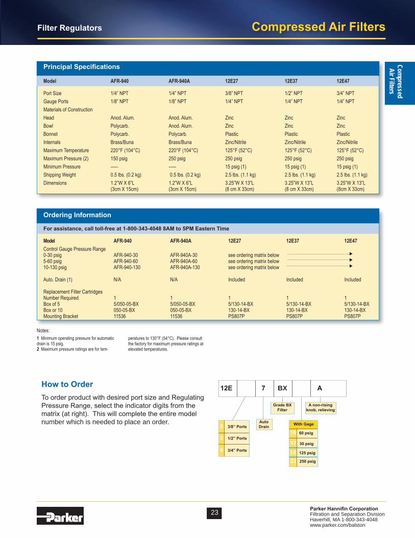
To order product with desired port size and Regulating Pressure Range, select the indicator digits from the matrix (at right). This will complete the entire model number which is needed to place an order.
How to Order 12E 7 BX A
2 3/8” Ports
3 1/2” Ports
4 3/4” Ports
AutoDrain
16 60 psig
17 30 psig
18 125 psig
21 250 psig
With Gage
A non-rising knob, relieving
Grade BXFilter
Model AFR-940 AFR-940A 12E27 12E37 12E47
Port Size 1/4” NPT 1/4” NPT 3/8” NPT 1/2” NPT 3/4” NPTGauge Ports 1/8” NPT 1/8” NPT 1/4” NPT 1/4” NPT 1/4” NPTMaterials of ConstructionHead Anod. Alum. Anod. Alum. Zinc Zinc ZincBowl Polycarb. Anod. Alum. Zinc Zinc ZincBonnet Polycarb. Polycarb. Plastic Plastic PlasticInternals Brass/Buna Brass/Buna Zinc/Nitrile Zinc/Nitrile Zinc/NitrileMaximum Temperature 220°F (104°C) 220°F (104°C) 125°F (52°C) 125°F (52°C) 125°F (52°C) Maximum Pressure (2) 150 psig 250 psig 250 psig 250 psig 250 psig Minimum Pressure ––– ––– 15 psig (1) 15 psig (1) 15 psig (1)Shipping Weight 0.5 lbs. (0.2 kg) 0.5 lbs. (0.2 kg) 2.5 lbs. (1.1 kg) 2.5 lbs. (1.1 kg) 2.5 lbs. (1.1 kg)Dimensions 1.2”W X 6”L 1.2”W X 6”L 3.25”W X 13”L 3.25”W X 13”L 3.25”W X 13”L (3cm X 15cm) (3cm X 15cm) (8 cm X 33cm) (8 cm X 33cm) (8cm X 33cm)
Principal Specifications
Ordering Information
For assistance, call toll-free at 1-800-343-4048 8AM to 5PM Eastern Time
Model AFR-940 AFR-940A 12E27 12E37 12E47Control Gauge Pressure Range0-30 psig AFR-940-30 AFR-940A-30 see ordering matrix below 5-60 psig AFR-940-60 AFR-940A-60 see ordering matrix below 10-130 psig AFR-940-130 AFR-940A-130 see ordering matrix below
Auto. Drain (1) N/A N/A Included Included Included
Replacement Filter Cartridges Number Required 1 1 1 1 1 Box of 5 5/050-05-BX 5/050-05-BX 5/130-14-BX 5/130-14-BX 5/130-14-BXBox or 10 050-05-BX 050-05-BX 130-14-BX 130-14-BX 130-14-BXMounting Bracket 11536 11536 PS807P PS807P PS807P
▼▼
▼

Compressed Air Filters
24 Parker Hannifin CorporationFiltration and Separation DivisionHaverhill, MA 1-800-343-4048 www.parker.com/balston
Com
pres
sed
Air F
ilter
s
Model 17L SeriesMany pneumatic system components and most tools re-quire oil lubrication for proper operation and long service life. This lubricant is typically carried by the air stream. Too little oil can cause excessive wear and premature failure. Too much oil is wasteful and can become a con-taminant. Use of the proper lubricator can greatly extend the life of expensive downstream pneumatic equipment.
The 17L Series Micro-Mist Lubricators offer proportional oil delivery over a wide range of air flows. The preci-sion needle valve assures repeatable oil delivery and provides simple adjustment of delivery rate. They are designed to generate oil droplets of 5 microns or smaller downstream to lubricate systems having complex piping arrangements. The 17L series are ideal for low and high flow applications with changing air flow.
Once the required flow is determined for a pneumatic ap-plication, the lubricator can be selected by using the flow
chart. To read the lubricator flow chart, first determine the inlet pressure that will be used. Find the appropriate pressure curve on the graph. Each graph will contain three pressure curves. If the required inlet pressure is not on the graph, interpolate a similar curve for the required pressure. Next, determine the acceptable pressure drop across the lubricator and locate it on the vertical axis. Find the intersection point of the accept-able pressure drop and the inlet pressure curve. At this
How to Select the Correct Lubricator
point, follow a vertical path downward to view the flow in SCFM. If the flow is too low, select a larger port size or body size to give the required flow. If the flow is higher than necessary, select a smaller port size or body size to give the required flow.
Model 17L22B Model 17L32B and 17L42B
Mist Lubricators
17L Series
0 5 10 15 20 25 30 35 40 45
00
10 20 30 40
7
1
2
3
4
5
6
0
.1
.2
.3
.4
50 60 70 80 90 100
Flow Characteristics17L22B 3/8 Inch Ports
Pre
ssu
re D
rop
- P
SIG
Pre
ssu
re D
rop
- b
ar
35 PSIG 90 PSIG 150 PSIGPrimary Pressure - PSIG
2.4 bar 6.2 bar 10.3 barPrimary Pressure - bar
Flow - SCFM
Flow - dm /s3
n
0 5 10 15 20 25 30 35 40 45 50 55 60 7065
00
10 20 30 40
7
1
2
3
4
5
6
0
.1
.2
.3
.4
50 60 70 80 90 100 110 120 130 140 150
Flow Characteristics17L32B 1/2 Inch Ports
&17L42B 3/4 Inch Ports
Pre
ssu
re D
rop
- P
SIG
Pre
ssu
re D
rop
- b
ar
35 PSIG 90 PSIG 150 PSIGPrimary Pressure - PSIG
2.4 bar 6.2 bar 10.3 barPrimary Pressure - bar
Flow - SCFM
Flow - dm /s3
n
25 Parker Hannifin CorporationFiltration and Separation DivisionHaverhill, MA 1-800-343-4048 www.parker.com/balston
Compressed Air FiltersCom
pressedAir Filters
Mist Lubricators
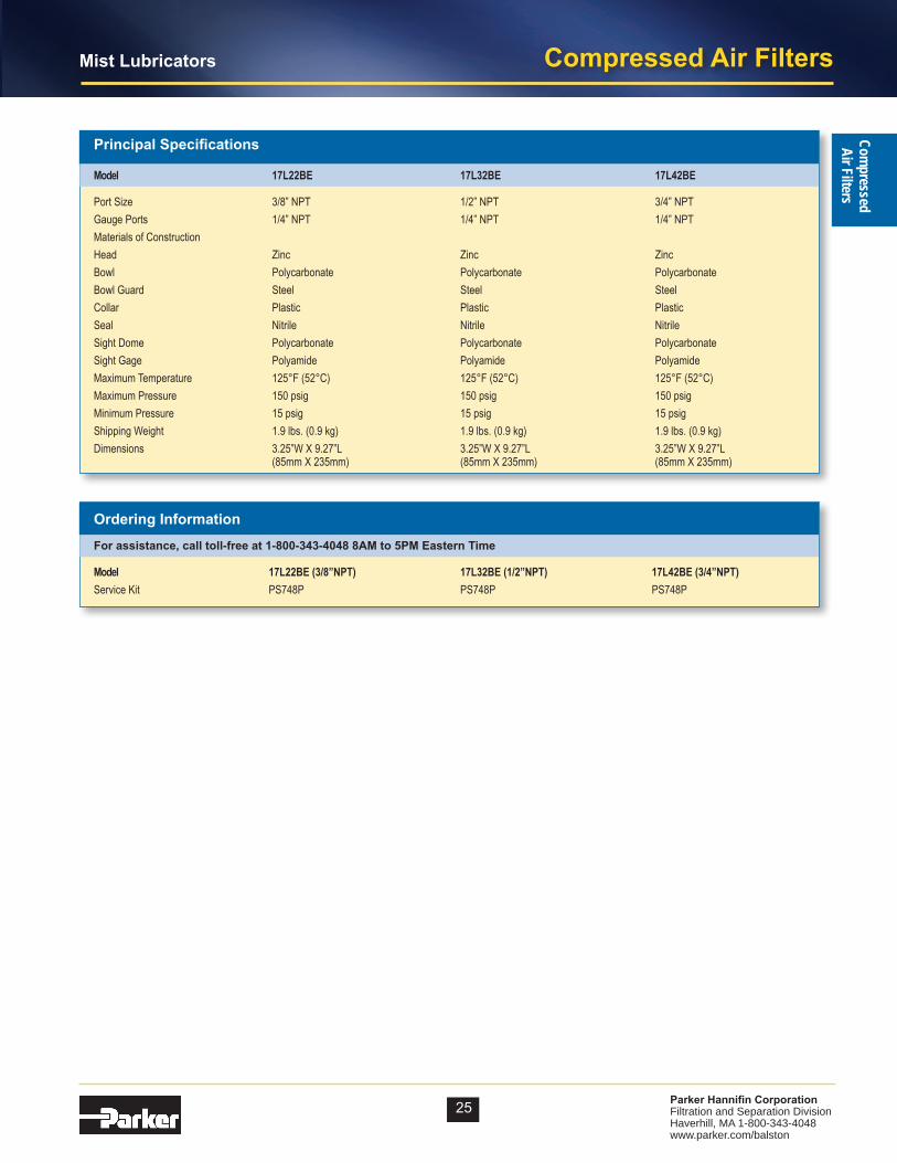
Model 17L22BE 17L32BE 17L42BE
Port Size 3/8” NPT 1/2” NPT 3/4” NPTGauge Ports 1/4” NPT 1/4” NPT 1/4” NPTMaterials of ConstructionHead Zinc Zinc ZincBowl Polycarbonate Polycarbonate PolycarbonateBowl Guard Steel Steel SteelCollar Plastic Plastic PlasticSeal Nitrile Nitrile NitrileSight Dome Polycarbonate Polycarbonate PolycarbonateSight Gage Polyamide Polyamide PolyamideMaximum Temperature 125°F (52°C) 125°F (52°C) 125°F (52°C) Maximum Pressure 150 psig 150 psig 150 psig Minimum Pressure 15 psig 15 psig 15 psig Shipping Weight 1.9 lbs. (0.9 kg) 1.9 lbs. (0.9 kg) 1.9 lbs. (0.9 kg)Dimensions 3.25”W X 9.27”L 3.25”W X 9.27”L 3.25”W X 9.27”L (85mm X 235mm) (85mm X 235mm) (85mm X 235mm)
Principal Specifications
Ordering Information For assistance, call toll-free at 1-800-343-4048 8AM to 5PM Eastern Time
Model 17L22BE(3/8”NPT) 17L32BE(1/2”NPT) 17L42BE(3/4”NPT)Service Kit PS748P PS748P PS748P
Compressed Air Filters
26 Parker Hannifin CorporationFiltration and Separation DivisionHaverhill, MA 1-800-343-4048 www.parker.com/balston
Com
pres
sed
Air F
ilter
s
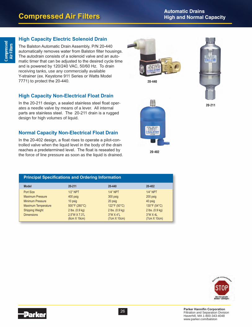
20-440
20-211
High Capacity Electric Solenoid DrainThe Balston Automatic Drain Assembly, P/N 20-440 automatically removes water from Balston filter housings. The autodrain consists of a solenoid valve and an auto-matic timer that can be adjusted to the desired cycle time and is powered by 120/240 VAC, 50/60 Hz. To drain receiving tanks, use any commercially available Y-strainer (ex. Keystone 911 Series or Watts Model 7771) to protect the 20-440.
High Capacity Non-Electrical Float DrainIn the 20-211 design, a sealed stainless steel float oper-ates a needle valve by means of a lever. All internal parts are stainless steel. The 20-211 drain is a rugged design for high volumes of liquid.
Normal Capacity Non-Electrical Float DrainIn the 20-402 design, a float rises to operate a pilot-con-trolled valve when the liquid level in the body of the drain reaches a predetermined level. The float is reseated by the force of line pressure as soon as the liquid is drained.
20-402
Principal Specifications and Ordering Information
Model 20-211 20-440 20-402Port Size 1/2” NPT 1/4” NPT 1/4” NPTMaximum Pressure 400 psig 300 psig 200 psigMinimum Pressure 10 psig 20 psig 40 psigMaximum Temperature 500°F (260°C) 122°F (50°C) 130°F (54°C)Shipping Weight 2 lbs. (0.9 kg) 2 lbs. (0.9 kg) 2 lbs. (0.9 kg)Dimensions 2.5”W X 7.3”L 3”W X 4”L 3”W X 4L (6cm X 19cm) (7cm X 10cm) (7cm X 10cm)
Automatic Drains High and Normal Capacity

27 Parker Hannifin CorporationFiltration and Separation DivisionHaverhill, MA 1-800-343-4048 www.parker.com/balston
Compressed Air FiltersCom
pressedAir Filters
Condensate DrainZero Air / Zero Energy Loss
What is a zero air loss condensate drain?
Zero air loss condensate drains are designed for economical removal of unwanted water, oil emulsions, and other liquids. These drains will only open when liquid is present and will not allow any compressed air to escape from the system.
Condensate is always present in a compressed air system. •
If condensate is not removed from a compressed air system, it will • adversely affect product quality and production efficiency and will eventually lead to costly downtime.
Why are they needed?
How does the Zero Air Loss Condensate drain compare to other drains?
Condensate Removal Method Disadvantages of Other Drains Advantages of ZLD
Manual Drain (operators must manually open valves to discharge condensate)
Float Drain (uses a float connected to a drain valve that opens when enough condensate is present and closes when condensate has been removed)
Solenoid Operated Drain Valves (uses a timer which allows user to open and close valve at specified intervals)
• Requires constant attention• Always leads to excess air loss because air escapes whenthe valve is left open to drain the condensate
• Float is susceptible to blockage from particulate contamination in condensate
• Often sticks in open (leaks excess air) or closed position (no condensate is drained)
• The period for which the valve is open might not be long enough for adequate drainage of accumulated condensate• The valve will operate even if little or no condensate is present, resulting in air loss• Often requires a strainer to remove particulate contamination which can block the inlet and outlet ports
• Automatically drains condensate• When a minimum level of condensate is reached, the valve closes in time before compressed air can escape
• Includes an integrated dirt screen between the level measurement and drain valve to protect the diaphragm valve• Particulate contamination is removed by the integrated dirt screen before fouling the moving parts
• Drain will remove condensate when liquid reaches the high level sensor• The drain will not operate until the liquid level reaches the high level sensor• Particulate contamination is removed by the integrated dirt screen before fouling the outlet port
Compressor with Aftercooler Receiver Tank Filter AirDryer Drip LegRemoves the condensate that is collected after the air cools in the aftercooler
Removes the condensate that is collected when the air cools inside of the receiver tank
Removes the condensate that is collected in the filter bowl
Removes the condensate that is collected in the air dryer
Point-of-use applications: removes the condensate from compressed air pipes in a plant
Finite®
Finite®
Finite®
Finite®
Finite®
Where are condensate drains used?

Compressed Air Filters
28 Parker Hannifin CorporationFiltration and Separation DivisionHaverhill, MA 1-800-343-4048 www.parker.com/balston
Com
pres
sed
Air F
ilter
sCondensate Drain
Zero Air / Zero Energy Loss
The co$t of compressed air when using a timed drain valve
The annual cost of compressed air was calculated using data from the U.S. Department of Energy and several compressed air consultants. The average annual energy cost to maintain a compressed air system is $0.23 per 1000 ft3. If a timed solenoid drain valve opens 3-4 times per hour, the cost of the wasted air will be $80 per valve, per year.
ZeroLossDrainsdon’twasteanycompressedairandhaveapaybackofapproximately6months-1year.
Annual Savings of a Zero Air Loss DrainVersus Timed Solenoid Drain Valves
$83$828
$1,656$2,484
$3,312$4,140
$0$500
$1,000$1,500$2,000$2,500$3,000$3,500$4,000$4,500
0 10 20 30 40 50
Number of Drain Valves in Facility
Annu
al E
nerg
y Co
sts
This collection vessel stores condensate until it is drained away.
This electronic level controller continuously monitors the liquid level inside the drain.
This depicts the electric drain valve. As soon as the electronic level controller detects a buildup of liquid, the valve opens and conden-sate is drained. When a minimum liquid level is reached, the valve closes before compressed air can escape.
The diaphragm valve ensures that contaminants are flushed out and that the condensate is prevented from forming an emulsion that would need expensive condensate treatment.
If an error has occurred (i.e. if the condensate cannot be dis-charged), the electronic control board (5) of the condensate drain generates an alarm signal. This allows timely detection of a problem and helps avoid excessive costs associated with condensate car-ryover to downstream components.
Unique swivel inlet connection for easy adaptability on 20-613 and 20-623. This allows the condensate line to be connected from the top or the rear. The 20-606 has a fixed inlet port with dynamic seal which allows the filter bowl to be removed while the drain is attached (not shown).
An additional liquid inlet on the 20-623 allows for the connection of a balance or vent line. This provides new connections so that conden-sate can no longer back up into the feed lines.
6
1
2
3
4
5
6
7
7
1
3
4
5
2
How does this drain work?
Easy installation &
servicing!

29 Parker Hannifin CorporationFiltration and Separation DivisionHaverhill, MA 1-800-343-4048 www.parker.com/balston
Compressed Air FiltersCom
pressedAir Filters
Condensate DrainZero Air / Zero Energy Loss
Model Number
Maximum CompressorCapacity
MaximumRefrigeratedDryer
Capacity*1
Maximum Filter Capacity*2
Pressure Range
TemperatureRange
Connection Size
Drain Capacity
Electrical Requirement
20-606 Not Recommended Not Recommended
424 SCFM(720 m3/h)
3 - 232 PSIG (0.2 - 16 bar)
35 -140°F(2 – 60 °C)
3/8” NPT 6 Gallons per day
120VAC
(60Hz)20-613 141 SCFM
(240 m3/h)283 SCFM(480 m3/h)
1413 SCFM(2,400 m3/h)
3 - 232 PSIG (0.2 - 16 bar)
35 -140°F(2 – 60 °C)
1/2” NPT 13 Gallons per day
120VAC
(60Hz)20-623 247 SCFM
(420 m3/h)494 SCFM(840 m3/h)
2472 SCFM(4,200 m3/h)
3 - 232 PSIG (0.2 - 16 bar)
35 -140°F(2 – 60 °C)
1/2” NPT 23 Gallons per day
120VAC
(60Hz)*1Based on 100 psi working pressure, air compressor inlet at 77°F at 60% RH, air discharge temperature of 95°F following the aftercooler, pressure dewpoint of 37°F after the refrigerated dryer.*2 Condensate from aftercooler or refrigerated dryer to be drained upstream – only for residual oil content or small quantities of condensate.Note: Drains are available with BSP threads; 24V/50 - 60Hz versions are available; 24V DC on request. A 6 ft. line cord will be included with each drain.
20-606
Dimensions (Inches) Dimensions (Inches) Dimensions (Inches)
Dimensions and Specifications
20-613 20-623

Compressed Air Filters
30 Parker Hannifin CorporationFiltration and Separation DivisionHaverhill, MA 1-800-343-4048 www.parker.com/balston
Com
pres
sed
Air F
ilter
s
Balston Differential Pressure IndicatorThe Balston Differential Pressure Indicator (DPI) is used to monitor the pressure drop across the filters or other components in a compressed air system. The DPI is sensitive in the range of 0 to 5 psi differential.
41-070
Note1 Installation kit includes fittings and tubing necessary for line-mounting the 41-070 DPI
41-070MountedonFilterAssembly
Principal Specifications & Ordering Information
Model 41-070 C02-2377Differential Pressure Indicator 41-070 C02-2377
Indicator and Installation Kit (1) 41-071 N/APort Size 1/8” NPT 3/8”-24Maximum Pressure 250 psig 250 psigMaximum Temperature 130°F (54°C) 130°F (54°C)Dimensions 1.7”W X 1.8”H 2.9”W X 2.25”H (4cm X 5cm) (7cm X 6cm)
C02-2377Mounted onFilterAssembly
C02-2377
Differential Pressure Indicator Kit
31 Parker Hannifin CorporationFiltration and Separation DivisionHaverhill, MA 1-800-343-4048 www.parker.com/balston
Compressed Air FiltersCom
pressedAir Filters
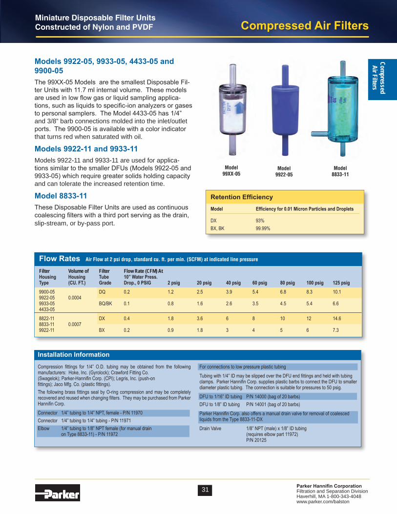
Miniature Disposable Filter UnitsConstructed of Nylon and PVDF
Model 99XX-05
Models 9922-05, 9933-05, 4433-05 and 9900-05The 99XX-05 Models are the smallest Disposable Fil-ter Units with 11.7 ml internal volume. These models are used in low flow gas or liquid sampling applica-tions, such as liquids to specific-ion analyzers or gases to personal samplers. The Model 4433-05 has 1/4” and 3/8” barb connections molded into the inlet/outlet ports. The 9900-05 is available with a color indicator that turns red when saturated with oil.
Models 9922-11 and 9933-11Models 9922-11 and 9933-11 are used for applica-tions similar to the smaller DFUs (Models 9922-05 and 9933-05) which require greater solids holding capacity and can tolerate the increased retention time.
Model 8833-11These Disposable Filter Units are used as continuous coalescing filters with a third port serving as the drain, slip-stream, or by-pass port.
Flow Rates Air Flow at 2 psi drop, standard cu. ft. per min. (SCFM) at indicated line pressure
Filter Volume of Filter Flow Rate (CFM) AtHousing Housing Tube 10”WaterPress.Type (CU.FT.) Grade Drop.,0PSIG 2psig 20psig 40psig 60psig 80psig 100psig 125psig9900-05 DQ 0.2 1.2 2.5 3.9 5.4 6.8 8.3 10.19922-05 0.00049933-05 BQ/BK 0.1 0.8 1.6 2.6 3.5 4.5 5.4 6.6 4433-05
8822-11 DX 0.4 1.8 3.6 6 8 10 12 14.68833-11 0.00079922-11 BX 0.2 0.9 1.8 3 4 5 6 7.3
Installation Information
Compression fittings for 1/4” O.D. tubing may be obtained from the following manufacturers: Hoke, Inc. (Gyrolock); Crawford Fitting Co.(Swagelok); Parker-Hannifin Corp. (CPI); Legris, Inc. (push-on fittings); Jaco Mfg. Co. (plastic fittings).The following brass fittings seal by O-ring compression and may be completely recovered and reused when changing filters. They may be purchased from Parker Hannifin Corp.
Connector 1/4” tubing to 1/4” NPT, female - P/N 11970Connector 1/4” tubing to 1/4” tubing - P/N 11971Elbow 1/4” tubing to 1/8” NPT female (for manual drain on Type 8833-11) - P/N 11972
For connections to low pressure plastic tubing
Tubing with 1/4” ID may be slipped over the DFU end fittings and held with tubing clamps. Parker Hannifin Corp. supplies plastic barbs to connect the DFU to smaller diameter plastic tubing. The connection is suitable for pressures to 50 psig.
DFU to 1/16” ID tubing P/N 14000 (bag of 20 barbs)DFU to 1/8” ID tubing P/N 14001 (bag of 20 barbs)
Parker Hannifin Corp. also offers a manual drain valve for removal of coalesced liquids from the Type 8833-11-DX
Drain Valve 1/8” NPT (male) x 1/8” ID tubing (requires elbow part 11972) P/N 20125
Model 9922-05
Model8833-11
Retention Efficiency
Model Efficiencyfor0.01MicronParticlesandDroplets
DX 93%BX, BK 99.99%

Compressed Air Filters
32 Parker Hannifin CorporationFiltration and Separation DivisionHaverhill, MA 1-800-343-4048 www.parker.com/balston
Com
pres
sed
Air F
ilter
sMiniature Disposable Filter UnitsConstructed of Nylon and PVDF
Principal Specifications
Model 9922-05 9900-05,9933-05 4433-05 9922-11 9933-11 8833-11
Inlet and Outlet Ports 1/4” Tubing 1/4” Tubing 1st Tier/Barb 1/4” Tube 1/4” Tubing 1/4” Tubing 1/4” Tubing 2nd Tier/Barb 3/8” TubeDrain None None None None None 1/4” TubingMaterial of Construction PVDF Nylon Nylon PVDF Nylon NylonFilter Cartridge Length 1.25” (3.2 cm) 1.25” (3.2 cm) 1.25” (3.2 cm) 2.25” (5.7 cm) 2.25” (5.7 cm) 2 1/4” Maximum Temperature (1) 275°F (135°C) 230°F (110°C) 230°F (110°C) 275°F (135°C) 230°F (110°C) 230°F (110°C)Maximum Pressure (2) 125 psig 125 psig 125 psig 125 psig (2) 125 psig (2) 125 psig (2)Dimensions 1.0”D X 3.25”L 1.0”D X 3.25”L 1.0”D X 3.43”L 1.4”D X 4.6”L 1.4”D X 4.6”L 1.4”D X 4.6”L (2.5 cm X 6 cm) (2.5 cm X 6 cm) (2.5 cm X 8.72 cm) (9.1 cm X 12 cm) (9.1cm X 12 cm) (9.1 cm X 12 cm)
Ordering Information
For assistance, call toll-free at 1-800-343-4048 8AM to 5PM Eastern Time
Model 9922-05 9900-05 4433-05 9933-05 9922-11 9933-11 8833-11Filter Cartridges 9922-05-❑ 9900-05-❑ 4433-05-❑ 9933-05-❑ 9922-11-❑ 9933-11-❑ 8833-11-❑ Box of 10Available in types Q and X (3)
Notes:1 At 0 psig
2 At 110°F (43°C)
3 To designate the grade of filter tube in the DFU, insert Grade letters after DFU designation. For example, to obtain a grade BQ filter tube in a DFU 9922-05, order: 9922-05-BQ. Please note the following limitations:
SuppliedWithDFU TheseGrades
4433-05, 9900-05, 9922-05, 9933-05 DQ, BQ, AQ (BK) (4)9922-11, 9933-11 DX, BX, AQ8822-11, 8833-11 DX, BX
4 BK Grade has a color indicating feature, which turns the cartridge red when saturated with oil. Available only in types 4433-05 and 9900-05.
33 Parker Hannifin CorporationFiltration and Separation DivisionHaverhill, MA 1-800-343-4048 www.parker.com/balston
Compressed Air FiltersCom
pressedAir Filters
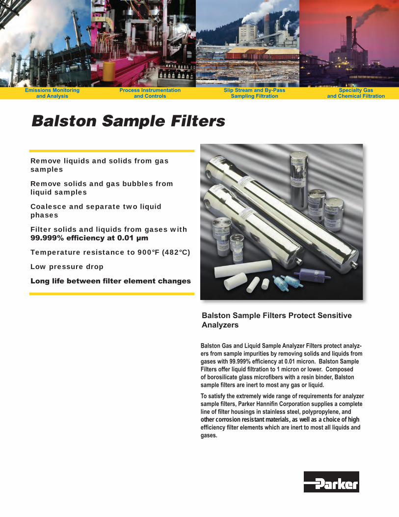
Remove liquids and solids from gas samples
Remove solids and gas bubbles from liquid samples
Coalesce and separate two liquid phases
Filter solids and liquids from gases with 99.999% efficiency at 0.01 µm
Temperature resistance to 900°F (482°C)
Low pressure drop
Long life between filter element changes
Balston Sample Filters Protect Sensitive Analyzers
BalstonGasandLiquidSampleAnalyzerFiltersprotectanalyz-ersfromsampleimpuritiesbyremovingsolidsandliquidsfromgaseswith99.999%efficiencyat0.01micron.BalstonSampleFiltersofferliquidfiltrationto1micronorlower.Composedofborosilicateglassmicrofiberswitharesinbinder,Balstonsamplefiltersareinerttomostanygasorliquid.Tosatisfytheextremelywiderangeofrequirementsforanalyzersamplefilters,ParkerHannifinCorporationsuppliesacompletelineoffilterhousingsinstainlesssteel,polypropylene,andother corrosion resistant materials, as well as a choice of high efficiencyfilterelementswhichareinerttomostallliquidsandgases.
Balston Sample Filters
Specialty Gas and Chemical Filtration
Emissions Monitoring and Analysis
Slip Stream and By-Pass Sampling Filtration
Process Instrumentation and Controls