Air-Cooled Liquid Scroll Chillers
22
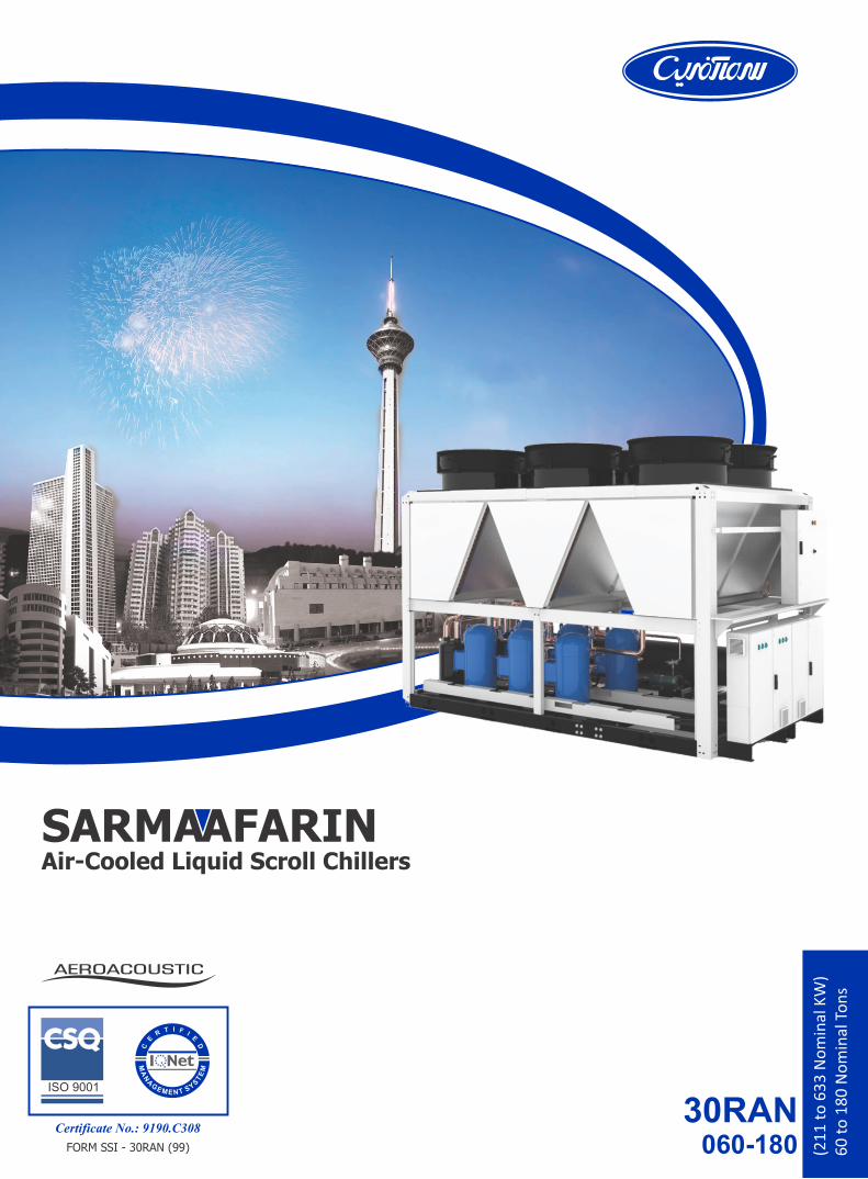
30RAN 060-180 Air-Cooled Liquid Scroll Chillers Certificate No.: 9190.C308 (211 to 633 Nominal KW) 60 to 180 Nominal Tons FORM SSI - 30RAN (99)
Transcript of Air-Cooled Liquid Scroll Chillers
30RAN060-180
Air-Cooled Liquid Scroll Chillers
Certificate No.: 9190.C308
(21
1 t
o 6
33
No
min
al K
W)
60
to
18
0 N
om
inal
To
ns
FORM SSI - 30RAN (99)
INTRODUCTION
1
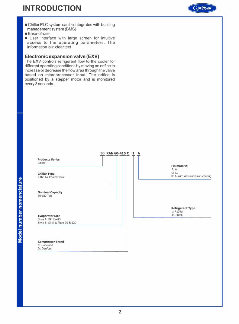
SarmaAfarin AeroSnap 30RAN series have compatible design to meet the efficiency demands of today and the future by providing premium air-cooled chiller packages for contractors, consulting engineers and building owners.
30RAN Features:n Positive displacement, scroll compressor.n Chlorine free R134a HFC Refrigerant also
compatible with R407Cn Easy to use Comfort Link controls and monitor.n Foot print most efficient air cooled models. n Full load ESEER up to ~11 and COP up to 3.2 so
that might exceeds the EN energy requirement as A+.
n The AeroSnap 30RAN chillers deliver superior efficiency through the entire operating range to keep costs and demand charges down.
Description30RAN liquid chillers are the best solution for commercial and industrial applications where installers, engineering and design departments and building owners require reduced installation costs, optimal performance and the highest quality. 30RAN's innovative chiller design provides savings at initial purchase, at installation, and for years afterward.The 30RAN liquid chillers are designed to meet current and future requirements in terms of energy efficiency and operating sound levels. They use the best technologies available today.n Ultra-quiet, high efficiency Scroll compressorsn Low pressure drop brazed plate heat exchangersn Low noise generation fansn PLC based control systemn Electronic expansion valve enabling operation at a
lower condensing pressure and improved use of the evaporator heat exchange surface
Features/BenefitsScroll Compressors are now the most used compression technology replacing reciprocating and screw compressors due to its undeniable superiority. Several, fully qualified multiple compressor assemblies (tandem and trio) are available to allow the use of scroll compressors into large capacity systems. Some of the benefits of this model are mentioned. n Scroll axial and radial compliance for superior
reliability and efficiencyn Wide scroll line-up for R407c and R134an Low TEWI (Total Equivalent Warming Impact)n Low sound and vibration leveln Low oil circulation raten Qualified tandem and trio configurations for
superior seasonal efficiency (ESEER)
Brazed plate evaporatorThe compact, high efficiency Brazed Plate Heat
Exchanger (BPHE) is used. It offers excellent heat transfer performance with a compact size and low weight, reducing structural steel requirements on the job site. The heat exchanger is manufactured in a precisely controlled vacuum-brazing process that allows the filler material to form a brazed joint at every contact point between the plates, creating complex channels. It is important to note that the strainer is required for all brazed plate heat exchangers; therefore, not considering it from the beginning may lead to the selection of the incorrect pump for the system and an incorrect evaluation of the overall installation cost. So strainer should use to provide protection at the evaporator inlet, particularly at system start-up when construction debris may be present in the piping system.Flow switch is included with the cooler. The switch is factory installed and tested and contains no moving parts for high reliability.
CondenserEfficient air cooled condenser with large coil surface area maximizes the heat transfer. Additionally, the internally enhanced seamless copper tubes arranged in a staggered row pattern mechanically expanded into SSI wavy aluminum condenser fins makes the condenser too efficient to redundant the heat.Condenser coils is mounted in V-shape with an open angle, allows quieter air flow across the coil.The low-noise axial fans employed to move large volume of air at exceptionally low sound levels with virtually vibration-free operation. May the sound diffuser be applied.
Environmental Caren R407C & R134a are safe, efficient, and
environmentally balanced refrigerant and also responsible choice for protecting the earth's ozone layer.
n Leak-tight refrigerant circuitn Reduction of leaks as no refrigerant connection is
made at site.n Verification of pressure transducers and
temperature sensors without transferring refrigerant charge
n Discharge shut-off valve and liquid line service valve for simplified maintenance
PLC based ControlPLC Controller is an advanced numeric control system that combines intelligence with great operating simplicity. The control constantly monitors all machine parameters and precisely manages the operation of compressors, electronic expansion devices, fans and evaporator water pump for optimum energy efficiencyn Energy managementn Leaving or entering cooler water temperature
controls chiller on/off.n Continuously control compressor capacity to match
required load
2
INTRODUCTION
n Chiller PLC system can be integrated with building management system (BMS)
n Ease-of-usen User interface with large screen for intuitive
access to the operating parameters. The information is in clear text
Electronic expansion valve (EXV) The EXV controls refrigerant flow to the cooler for different operating conditions by moving an orifice to increase or decrease the flow area through the valve based on microprocessor input. The orifice is positioned by a stepper motor and is monitored every 3 seconds.
Mo
del n
um
ber
no
men
cla
ture
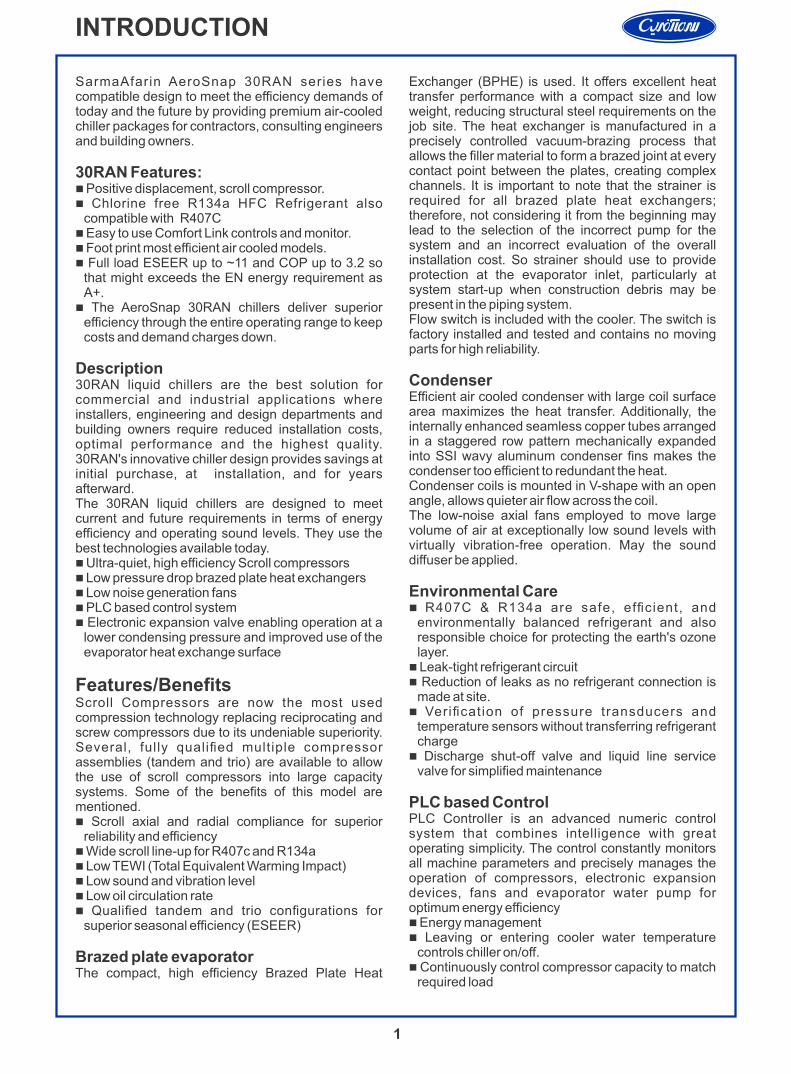
30 RAN 60- C 1 A
Products SeriesChiller
Chiller TypeRAN: Air Cooled Scroll
Nominal Capacity60-180 Ton
Refrigerant Type1: R134a4: R407C
415
Evaporator SizeStyle A: BPHE-415Style B: Shell & Tube-70 & 120
Compressor BrandC: CopelandD: Danfoss
Fin material A: AlC: CuB: Al with Anti-corrosion coating
3
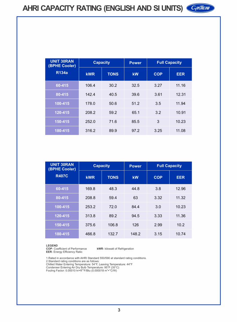
AHRI CAPACITY RATING (ENGLISH AND SI UNITS)
UNIT 30RAN (BPHE Cooler)
R134a
LEGEND COP - Coefficient of Performance kWR - kilowatt of RefrigerationEER - Energy Efficiency Ratio
1. Rated in accordance with AHRI Standard 550/590 at standard rating conditions.2. Standard rating conditions are as follows:Chilled Water Entering Temperature: 54°F, Leaving Temperature: 44°FCondenser Entering Air Dry Bulb Temperature: 95°F (35°C)
2 2Fouling Factor: 0.00010 hr×ft °F/Btu (0.000018 m ×°C/W)
Capacity Power Full Capacity
kWR TONS kW COP EER
60-415
80-415
100-415
120-415
150-415
180-415
106.4 30.2 32.5 3.27 11.16
142.4 40.5 39.6 3.61 12.31
178.0 50.6 51.2 3.5 11.94
208.2 59.2 65.1 3.2 10.91
252.0 71.6 85.5 3 10.23
316.2 89.9 97.2 3.25 11.08
UNIT 30RAN (BPHE Cooler)
R407C
Capacity Power Full Capacity
kWR TONS kW COP EER
60-415 169.8 48.3 44.8 3.8 12.96
80-415 208.8 59.4 63 3.32 11.32
100-415 253.2 72.0 84.4 3.0 10.23
120-415 313.8 89.2 94.5 3.33 11.36
150-415 375.6 106.8 126 2.99 10.2
180-415 466.8 132.7 148.2 3.15 10.74
LEGEND COP- Coefficient of Performance kWR- kilowatt of RefrigerationEER- Energy Efficiency Ratio
1. Rated in accordance with AHRI Standard 550/590 at standard rating conditions.2. Standard rating conditions are as follows:Chilled Water Entering Temperature: 54°F, Leaving Temperature: 44°FCondenser Entering Air Dry Bulb Temperature: 95°F (35°C)
2 2Fouling Factor: 0.00010 hr×ft °F/Btu (0.000018 m ×°C/W)
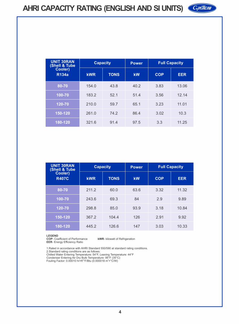
UNIT 30RAN Capacity Power Full Capacity
kWR TONS kW COP EER
(Shell & TubeCooler)
R407C
80-70
100-70
120-70
150-120
180-120
211.2 60.0 63.6 3.32 11.32
243.6 69.3 84 2.9 9.89
298.8 85.0 93.9 3.18 10.84
367.2 104.4 126 2.91 9.92
445.2 126.6 147 3.03 10.33
UNIT 30RAN Capacity Power Full Capacity
kWR TONS kW COP EER
(Shell & TubeCooler)
R134a
80-70
100-70
120-70
150-120
180-120
154.0 43.8 40.2 3.83 13.06
183.2 52.1 51.4 3.56 12.14
210.0 59.7 65.1 3.23 11.01
261.0 74.2 86.4 3.02 10.3
321.6 91.4 97.5 3.3 11.25
4
AHRI CAPACITY RATING (ENGLISH AND SI UNITS)
5
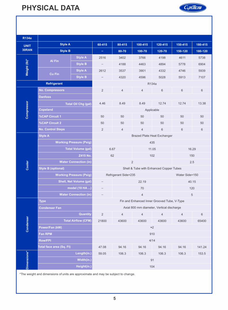
PHYSICAL DATA
21800
*The weight and dimensions of units are approximate and may be subject to change.
UNIT
30RAN
Copeland
Total Oil Chg (gal)
Working Pressure (Psig)
Total Volume (gal)
Z415 No.
Water Connection (in)
Working Pressure (Psig)
Shell, Net Volume (gal)
model (10 HA ...)
Water Connection (in)
Quantity
Total Airflow (CFM)
Length(in.)
Width(in.)
Height(in.)
No. Compressors
Danfoss
%CAP Circuit 1
%CAP Circuit 2
No. Control Steps
Style A
Style B (optional)
Type
Condenser Fan
Power/Fan (kW)
Fan RPM
Row/FPI
Co
mp
resso
rC
oo
ler
Dim
en
sio
ns*
Style A
Style B
Al Fin Style A
Style B
Cu Fin Style A
Style B
Refrigerant
Total face area (Sq. Ft)
Co
nd
en
ser
Weig
ht
(lb
)*
60-415 80-415 100-415 120-415 150-415 180-415
_ 80-70 100-70 120-70 150-120 180-120
2516 3402 3766 4198 4611 5738
_ 4188 4463 4894 5778 6904
2612 3537 3901 4332 4746 5939
_ 4320 4596 5028 5913 7107
R134a
2 4 4 6 6 6
4.46 8.49 8.49 12.74 12.74 13.38
50 50 50 50 50 50
50 50 50 50 50 50
2 4 4 6 6 6
Brazed Plate Heat Exchanger
435
6.67 11.05 16.29
62 102 150
2 2.5
Shell & Tube with Enhanced Copper Tubes
Refrigerant Side=235 Water Side=150
_ 22.19 40.15
_ 70 120
5_
4
Fin and Enhanced Inner Grooved Tube, V-Type
Axial 800 mm diameter, Vertical discharge
2 4 4 4 4 6
43600 43600 43600 43600 65400
≈2
910
4/14
47.08 94.16 94.16 94.16 94.16 141.24
59.05 106.3 106.3 106.3 106.3 153.5
91
104
Applicable
R134a

5_
4
6
PHYSICAL DATA
UNIT
30RAN
Copeland
Total Oil Chg (gal)
Working Pressure (Psig)
Total Volume (gal)
Z415 No.
Water Connection (in)
Working Pressure (Psig)
Shell, Net Volume (gal)
model (10 HA ...)
Water Connection (in)
Quantity
Total Airflow (CFM)
Length(in.)
Width(in.)
Height(in.)
No. Compressors
Danfoss
%CAP Circuit 1
%CAP Circuit 2
No. Control Steps
Style A
Style B (optional)
Type
Condenser Fan
Power/Fan (kW)
Fan RPM
Row/FPI
Co
mp
resso
rC
oo
ler
Dim
en
sio
ns*
Style A
Style B
Al Fin Style A
Style B
Cu Fin Style A
Style B
Refrigerant
Total face area (Sq. Ft)
Co
nd
en
ser
Weig
ht
(lb
)*
60-415 80-415 100-415 120-415 150-415 180-415
_ 80-70 100-70 120-70 150-120 180-120
2912 3402 3766 5053 5457 6592
_ 4188 4463 5751 6625 7761
3047 3537 3901 5255 5659 6862
_ 4320 4596 5952 6836 8031
R407C
2 4 4 6 6 6
50 50 50 50 50 50
50 50 50 50 50 50
2 4 4 6 6 6
Brazed Plate Heat Exchanger
435
6.67 11.05 16.29
62 102 150
2 2.5
Shell & Tube
Refrigerant Side=235 Water Side=150
_ 22.19 40.15
_ 070 120
Fin and Enhanced Inner Grooved Tube, V-Type
Axial 800 mm diameter, Vertical discharge
4 4 4 6 6 8
43600 43600 43600 65400 65400 87200
1.94
910
4/14
94.16 94.16 94.16 141.24 141.24 188.3
106.3 106.3 106.3 153.5 153.5 200.8
91
104
4.46 8.49 8.49 12.74 12.74 13.38
*The weight and dimensions of units are approximate and may be subject to change.
Applicable
R407C
7
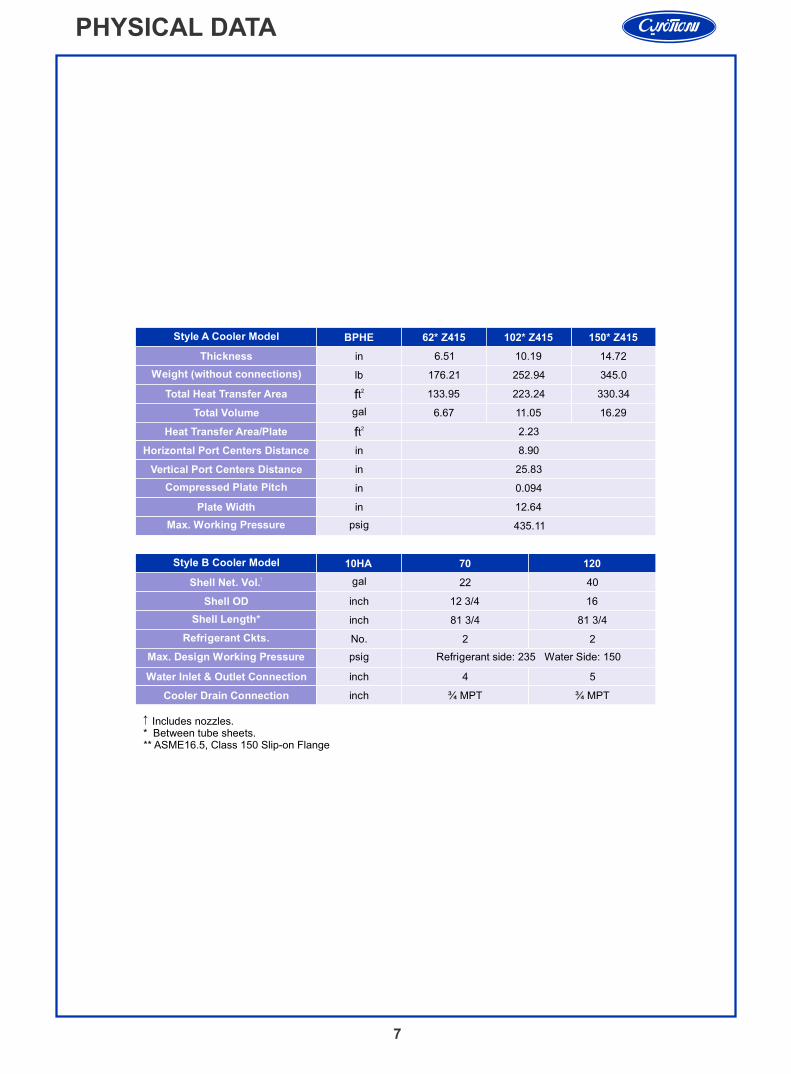
PHYSICAL DATA
↑ Includes nozzles. * Between tube sheets.** ASME16.5, Class 150 Slip-on Flange
Style A Cooler Model
Thickness
Weight (without connections)
Total Heat Transfer Area
Total Volume
Heat Transfer Area/Plate
Horizontal Port Centers Distance
Vertical Port Centers Distance
Compressed Plate Pitch
Plate Width
Max. Working Pressure
Style B Cooler Model
↑Shell Net. Vol.
Shell OD
Shell Length*
Refrigerant Ckts.
Max. Design Working Pressure
Water Inlet & Outlet Connection
Cooler Drain Connection
BPHE 62* Z415 102* Z415 150* Z415
in 6.51 10.19 14.72
lb 176.21 252.94 345.0
2tf 133.95 223.24 330.34
gal 6.67 11.05 16.29
2.23
in 8.90
in 25.83
in 0.094
in 12.64
psig 435.11
10HA 70 120
gal 22 40
inch 12 3/4 16
inch 81 3/4 81 3/4
No. 2 2
psig Refrigerant side: 235 Water Side: 150
inch 4 5
inch ¾ MPT ¾ MPT
2tf
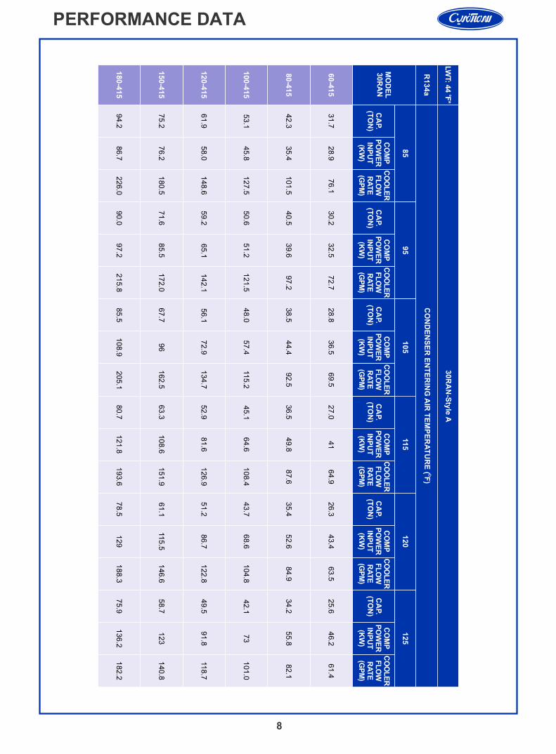
PERFORMANCE DATA
8
CA
P.
(TO
N)
CA
P.
(TO
N)
CA
P.
(TO
N)
CA
P.
(TO
N)
CA
P.
(TO
N)
CA
P.
(TO
N)
oLW
T: 4
4 F
*
R134a
MO
DE
L30R
AN
30R
AN
-Sty
le A
94.2
75.2
61.9
53.1
42.3
31.7
85
OC
ON
DE
NS
ER
EN
TE
RIN
G A
IR T
EM
PE
RA
TU
RE
(F
)
86.7
76.2
58.0
45.8
35.4
28.9
226.0
180.5
148.6
127.5
101.5
76.1
90.0
71.6
59.2
50.6
40.5
30.2
95
97.2
85.5
65.1
51.2
39.6
32.5
215.8
172.0
142.1
121.5
97.2
72.7
85.5
67.7
56.1
48.0
38.5
28.8
105
108.9
96
72.9
57.4
44.4
36.5
205.1
162.5
134.7
115.2
92.5
69.5
80.7
63.3
52.9
45.1
36.5
27.0
115
121.8
108.6
81.6
64.6
49.8
41
193.6
151.9
126.9
108.4
87.6
64.9
78.5
61.1
51.2
43.7
35.4
26.3
120
129
115.5
86.7
68.6
52.6
43.4
188.3
146.6
122.8
104.8
84.9
63.5
75.9
58.7
49.5
42.1
34.2
25.6
125
136.2
123
91.8
73
55.8
46.2
182.2
140.8
118.7
101.0
82.1
61.4
CO
MP
PO
WE
RIN
PU
T(K
W)
CO
MP
PO
WE
RIN
PU
T(K
W)
CO
MP
PO
WE
RIN
PU
T(K
W)
CO
MP
PO
WE
RIN
PU
T(K
W)
CO
MP
PO
WE
RIN
PU
T(K
W)
CO
MP
PO
WE
RIN
PU
T(K
W)
CO
OL
ER
FL
OW
RA
TE
(GP
M)
CO
OL
ER
FL
OW
RA
TE
(GP
M)
CO
OL
ER
FL
OW
RA
TE
(GP
M)
CO
OL
ER
FL
OW
RA
TE
(GP
M)
CO
OL
ER
FL
OW
RA
TE
(GP
M)
CO
OL
ER
FL
OW
RA
TE
(GP
M)
60-4
15
80-4
15
100-4
15
120-4
15
150-4
15
180-4
15
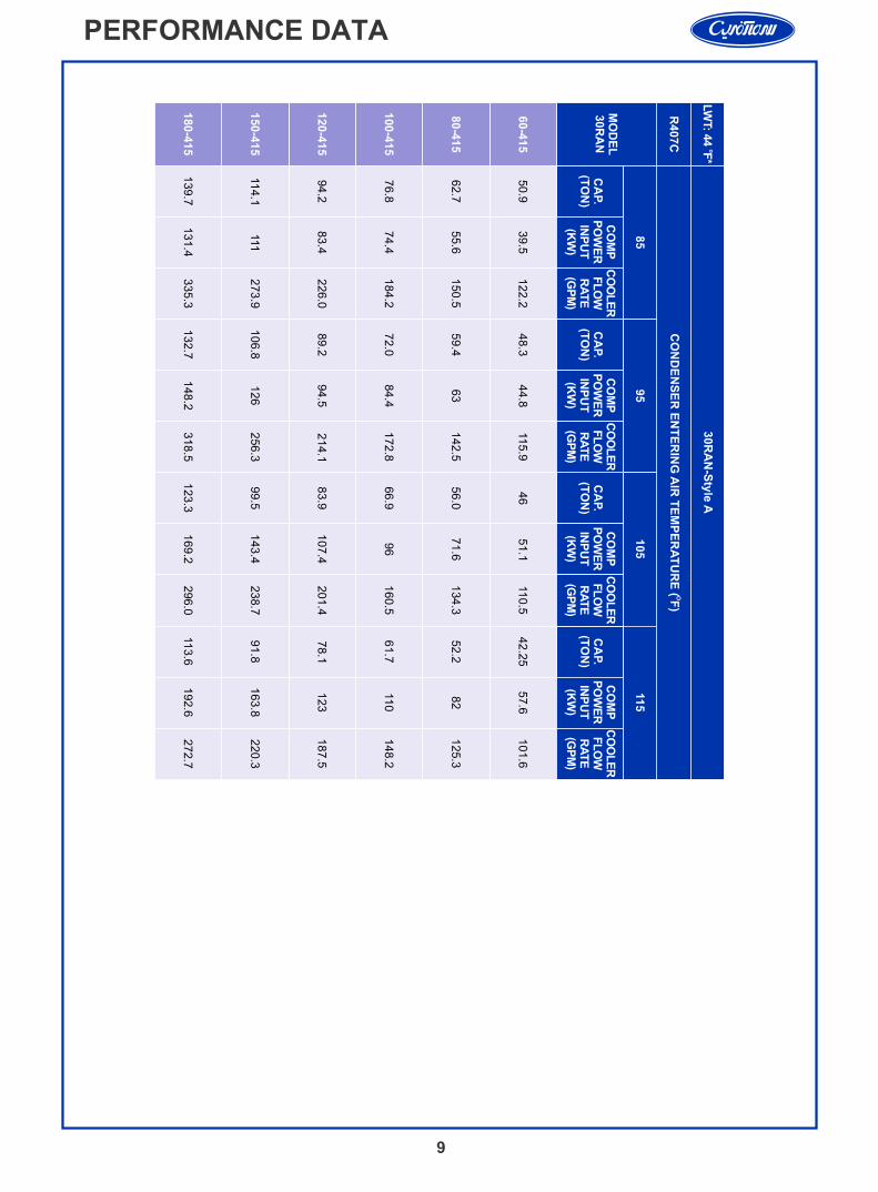
PERFORMANCE DATA
9
CA
P.
(TO
N)
CA
P.
(TO
N)
CA
P.
(TO
N)
CA
P.
(TO
N)
R407C
MO
DE
L30R
AN
30R
AN
-Sty
le A
85
95
105
115
CO
MP
PO
WE
RIN
PU
T(K
W)
CO
MP
PO
WE
RIN
PU
T(K
W)
CO
MP
PO
WE
RIN
PU
T(K
W)
CO
MP
PO
WE
RIN
PU
T(K
W)
CO
OL
ER
FL
OW
RA
TE
(GP
M)
CO
OL
ER
FL
OW
RA
TE
(GP
M)
CO
OL
ER
FL
OW
RA
TE
(GP
M)
CO
OL
ER
FL
OW
RA
TE
(GP
M)
60-4
15
80-4
15
100-4
15
120-4
15
150-4
15
180-4
15
139.7
114.1
94.2
76.8
62.7
50.9
131.4
111
83.4
74.4
55.6
39.5
335.3
273.9
226.0
184.2
150.5
122.2
132.7
106.8
89.2
72.0
59.4
48.3
148.2
126
94.5
84.4
63
44.8
318.5
256.3
214.1
172.8
142.5
115.9
123.3
99.5
83.9
66.9
56.0
46
169.2
143.4
107.4
96
71.6
51.1
296.0
238.7
201.4
160.5
134.3
110.5
113.6
91.8
78.1
61.7
52.2
42.2
5
192.6
163.8
123
110
82
57.6
272.7
220.3
187.5
148
.2
125.3
101.6
oLW
T: 4
4 F
*
OC
ON
DE
NS
ER
EN
TE
RIN
G A
IR T
EM
PE
RA
TU
RE
(F
)
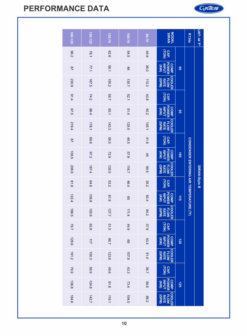
PERFORMANCE DATA
10
CA
P.
(TO
N)
CA
P.
(TO
N)
CA
P.
(TO
N)
CA
P.
(TO
N)
CA
P.
(TO
N)
CA
P.
(TO
N)
R134a
MO
DE
L30R
AN
30R
AN
-Sty
le B
85
95
105
115
120
125
CO
MP
PO
WE
RIN
PU
T(K
W)
CO
MP
PO
WE
RIN
PU
T(K
W)
CO
MP
PO
WE
RIN
PU
T(K
W)
CO
MP
PO
WE
RIN
PU
T(K
W)
CO
MP
PO
WE
RIN
PU
T(K
W)
CO
MP
PO
WE
RIN
PU
T(K
W)
CO
OL
ER
FL
OW
RA
TE
(GP
M)
CO
OL
ER
FL
OW
RA
TE
(GP
M)
CO
OL
ER
FL
OW
RA
TE
(GP
M)
CO
OL
ER
FL
OW
RA
TE
(GP
M)
CO
OL
ER
FL
OW
RA
TE
(GP
M)
CO
OL
ER
FL
OW
RA
TE
(GP
M)
80-7
0
100-7
0
120-7
0
150-1
20
180-1
20
96.2
78.1
62.6
54.5
45.9
87
77.1
58.1
46
36.0
230.9
187.5
150.2
130.7
110.3
91.4
74.2
59.7
52.1
43.8
97.5
86.4
65.1
51.4
40.2
219.4
178.1
143.3
125.0
105.1
87
69.8
56.5
49.5
41.6
109.5
97.2
72.9
57.8
45
208.8
167.4
135.5
118.7
99.9
81.9
64.8
53.2
46.4
39.2
122.4
109.8
81.9
65
50.4
196.5
155.6
127.7
111.4
94.2
79.7
62.6
51.5
44.9
37.9
129.6
117
86.7
69
53.4
191.2
150.3
123.6
107.8
91.0
76.9
59.9
49.6
43.3
36.7
136.8
124. 8
91.8
73.4
56.6
184.6
143.7
119.1
104.0
88.2
oLW
T: 4
4 F
*
OC
ON
DE
NS
ER
EN
TE
RIN
G A
IR T
EM
PE
RA
TU
RE
(F
)

PERFORMANCE DATA
11
CA
P.
(TO
N)
CA
P.
(TO
N)
CA
P.
(TO
N)
CA
P.
(TO
N)
MO
DE
L30R
AN
30R
AN
-Sty
le B
85
95
105
115
CO
MP
PO
WE
RIN
PU
T(K
W)
CO
MP
PO
WE
RIN
PU
T(K
W)
CO
MP
PO
WE
RIN
PU
T(K
W)
CO
MP
PO
WE
RIN
PU
T(K
W)
CO
OL
ER
FL
OW
RA
TE
(GP
M)
CO
OL
ER
FL
OW
RA
TE
(GP
M)
CO
OL
ER
FL
OW
RA
TE
(GP
M)
CO
OL
ER
FL
OW
RA
TE
(GP
M)
80-7
0
100-7
0
120-7
0
150-1
20
180-1
20
134.4
111.7
90.1
74.1
63.3
129.6
111
82.8
73.8
56.2
322.6
268.2
216.2
178.0
152.0
126.6
104.4
85.0
69.3
60.0
147
126
93.9
84
63.6
303.8
250.6
203.9
166.2
144.1
117.7
96.9
79.7
64.7
56.4
166.8
143.4
106.8
95.6
72.4
282.5
232.6
191.2
155.3
135.4
107.8
89.7
74.2
59.8
52.3
190.2
164.4
121.8
109.6
82.8
258
.8
215.3
178.1
143.6
125.5
LEGENDLCWT- Leaving chilled water temperatureCAP.- Capacity, tons of refrigerationkW- Compressor motor Input at rated voltage (kW)
o*Cooler water temperature rise of 10 F-For other rating conditions please contact SSI sales departement
oLW
T: 4
4 F
*
OC
ON
DE
NS
ER
EN
TE
RIN
G A
IR T
EM
PE
RA
TU
RE
(F
)R
407C
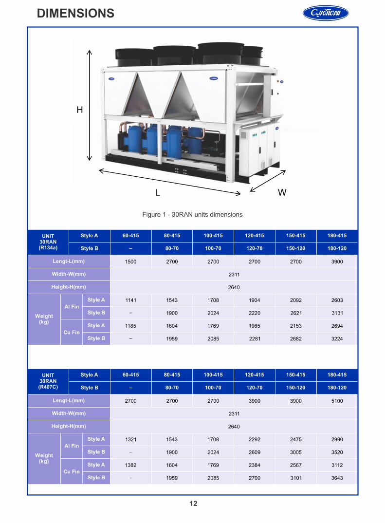
DIMENSIONS
12
UNIT30RAN(R134a)
UNIT30RAN(R407C)
Lengt-L(mm)
Width-W(mm)
Height-H(mm)
Weight(kg)
Al Fin
Style A
Style B
Cu Fin
Style A
Style B
Style A 60-415 80-415 100-415 120-415 150-415 180-415
Style B _ 80-70 100-70 120-70 150-120 180-120
Style A 60-415 80-415 100-415 120-415 150-415 180-415
Style B _ 80-70 100-70 120-70 150-120 180-120
Lengt-L(mm) 1500 2700 2700 2700 2700 3900
Width-W(mm) 2311
Height-H(mm) 2640
Weight(kg)
Al Fin
Style A 1141 1543 1708 1904 2092 2603
Style B _ 1900 2024 2220 2621 3131
Cu Fin
Style A 1185 1604 1769 1965 2153 2694
Style B _ 1959 2085 2281 2682 3224
2700 2700 2700 3900 3900 5100
2311
2640
1321 1543 1708 2292 2475 2990
_ 1900 2024 2609 3005 3520
1382 1604 1769 2384 2567 3112
_ 1959 2085 2700 3101 3643
H
L W
Figure 1 - 30RAN units dimensions
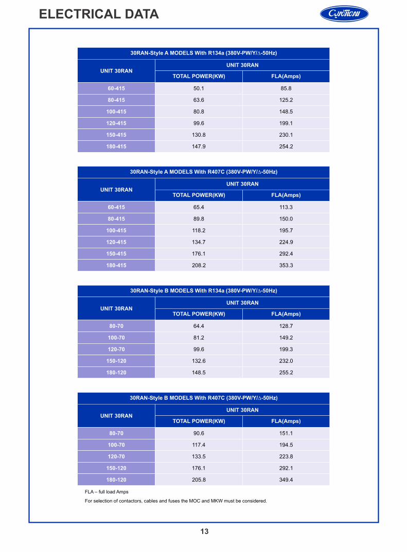
ELECTRICAL DATA
13
FLA – full load Amps
For selection of contactors, cables and fuses the MOC and MKW must be considered.
30RAN-Style A MODELS With R134a (380V-PW/Y/∆-50Hz)
UNIT 30RAN UNIT 30RAN
TOTAL POWER(KW) FLA(Amps)
60-415 50.1 85.8
80-415 63.6 125.2
100-415 80.8 148.5
120-415 99.6 199.1
150-415 130.8 230.1
180-415 147.9 254.2
30RAN-Style A MODELS With R407C (380V-PW/Y/∆-50Hz)
UNIT 30RAN UNIT 30RAN
TOTAL POWER(KW) FLA(Amps)
60-415 65.4 113.3
80-415 89.8 150.0
100-415 118.2 195.7
120-415 134.7 224.9
150-415 176.1 292.4
180-415 208.2 353.3
30RAN-Style B MODELS With R407C (380V-PW/Y/∆-50Hz)
UNIT 30RAN UNIT 30RAN
TOTAL POWER(KW) FLA(Amps)
80-70 90.6 151.1
100-70 117.4 194.5
120-70 133.5 223.8
150-120 176.1 292.1
180-120 205.8 349.4
30RAN-Style B MODELS With R134a (380V-PW/Y/∆-50Hz)
80-70 64.4 128.7
100-70 81.2 149.2
120-70 99.6 199.3
150-120 132.6 232.0
180-120 148.5 255.2
UNIT 30RAN UNIT 30RAN
TOTAL POWER(KW) FLA(Amps)
14
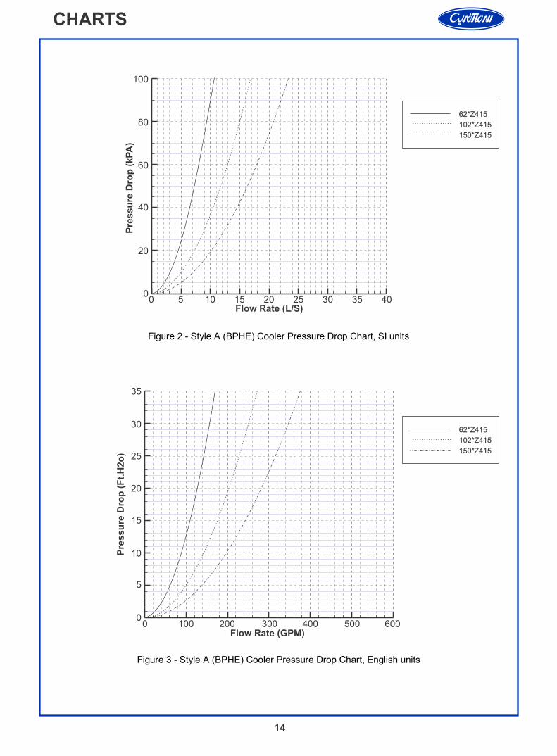
CHARTS
Figure 2 - Style A (BPHE) Cooler Pressure Drop Chart, SI units
Figure 3 - Style A (BPHE) Cooler Pressure Drop Chart, English units
0 5 10 15 20 25 30 35 400
20
40
60
80
100
62*Z415
102*Z415
150*Z415
Flow Rate (L/S)
Pre
ssu
re D
rop
(kP
A)
1000
5
10
15
20
25
62*Z415
102*Z415
150*Z415
Flow Rate (GPM)
Pre
ssu
re D
rop
(F
t.H
2o
)
0 200 300 400 500 600
30
35

Figure 5 - Style B (Shell & Tube) Cooler Pressure Drop Chart, English units
1000
5
10
15
20
25
10 HA 70
10 HA120
Flow Rate (GPM)
Pre
ssu
re D
rop
(F
t.H
2o
)
0 200 300 400 500 600
30
15
CHARTS
Figure 4 - Style B (Shell & Tube) Cooler Pressure Drop Chart, SI units
0 5 10 15 20 25 30 35 400
20
40
60
80
100
Flow Rate (L/S)
Pre
ssu
re D
rop
(kP
A)
10 HA 70
10 HA120
35
REMOTE MONITORING SYSTEM
16
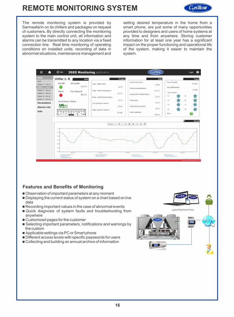
Features and Benefits of Monitoring
n Observation of important parameters at any momentn Displaying the current status of system on a chart based on live
datan Recording important values in the case of abnormal eventsn Quick diagnosis of system faults and troubleshooting from
anywheren Customized pages for the customer n Selecting important parameters, notifications and warnings by
the customn Applicable settings via PC or Smart phonen Different access levels with specific passwords for usersn Collecting and building an annual archive of information
The remote monitoring system is provided by Sarmaafarin on its chillers and packages on request of customers. By directly connecting the monitoring system to the main control unit, all information and alarms can be transmitted to any location via a fixed connection line. Real time monitoring of operating conditions on installed units, recording of data in abnormal situations, maintenance management and
setting desired temperature in the home from a smart phone, are just some of many opportunities provided to designers and users of home systems at any time and from anywhere. Storing customer information for at least one year has a significant impact on the proper functioning and operational life of the system, making it easier to maintain the system.

Chiller location and clearancesThe 30RAN unit must be installed outdoors.Do not locate near sound-sensitive areas without proper acoustic consideration. For applications requiring mounting a chiller on a building rooftop, consideration should be given to using rubber-in-shear or spring isolators to minimize structure borne transmission. Unit must be level when installed to ensure proper oil return to the compressors. Clearances must be provided around chillers for airflow, service and local code requirements. Chiller fan discharge must be at least as high as adjacent solid walls. Installation in pits is not recommended. Ensure adequate clearance between adjacent chillers is maintained.When chillers are arranged in parallel, a minimum of 10 ft (3048 mm) between chillers is recommended. Acceptable clearance between the chiller and a single wall may be reduced to 3 ft (914.4 mm) on one side or end opposite the control panel without sacrificing performance as long as the remaining three sides are unrestricted. Clearances between chillers in dual chiller applications may be reduced to 6 ft (1.8 m) without sacrificing performance provided the remaining sides are unrestricted.
Parallel chillersWhen chiller capacities greater than can be supplied by a single 30RAN chiller is required, or where standby capability is desired, chillers may be installed in parallel. Units may be of the same or different sizes with this piping arrangement.However, cooler flow rates must be balanced to ensure proper flow to each chiller. Unit software is capable of controlling two parallel units as a single plant by making use of the dual chiller control feature. If the dual chiller algorithm is used, and the machines are installed in parallel, one chiller must be configured as the master chiller and the other as the slave. With this configuration, an additional chilled water temperature thermistor must be installed for each chiller.Parallel chiller control with dedicated pumps is recommended.The chiller must start and stop its own water pump located in its own piping. Check valves are required at the discharge of each pump. If pumps are not dedicated for each chiller, then isolation valves are
required. Each chiller must open and close its own isolation valve through the unit control (the valve must be connected to the pump outputs).
Series chillersWhere a large temperature drop (greater than 20°F [11.1°C]) is desired, or where chiller capacities greater than what can be supplied by a single 30RAN chiller are required, or where standby capability is required, chillers may be installed in series. The leaving fluid temperature sensors need not be relocated. However, the cooler minimum entering fluid temperature limitations should be considered for the chillers located downstream of other chillers.
Dual chiller controlThere are several advantages to this type of control:Ÿ Redundancy (multiple circuits)Ÿ Better low load control (lower tonnage capability)Ÿ Lower rigging lift weights (2 machines rather than 1 large machine)Ÿ Chiller lead-lag operation (evens the wear between the two machines)
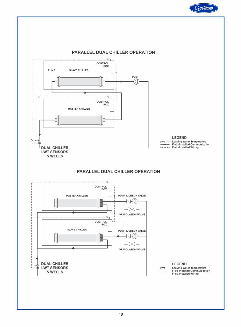
Parallel dual chiller operation — Parallel
chiller operation is the recommended option for dual chiller control. In this case, each chiller must control its own dedicated pump or isolation valve. Balancing valves are recommended to ensure proper flow in each chiller. Two field supplied and installed leaving water temperature sensors are required, one for each module, for this function to operate properly.Consider adding additional isolation valves to isolate each chiller to allow for service on a machine, and still allow for partial capacity from the other chiller.
Series dual chiller operation — Series
chiller operation is an alternate control. Certain applications might require that the two chillers be connected in series.
17
APPLICATION DATA
18
MASTER CHILLER
CONTROLBOX
PUMP
CONTROLBOX
PUMP
LEGENDLeaving Water TemperatureField-Installed CommunicationField-Installed Wiring
LWT
SLAVE CHILLER
PUMP & CHECK VALVE
CONTROLBOX
CONTROLBOX
OR ISOLATION VALVE
PUMP & CHECK VALVE
OR ISOLATION VALVE
MASTER CHILLER
SLAVE CHILLER
PARALLEL DUAL CHILLER OPERATION
LEGENDLeaving Water TemperatureField-Installed CommunicationField-Installed Wiring
LWT
PARALLEL DUAL CHILLER OPERATION
DUAL CHILLERLWT SENSORS
& WELLS
DUAL CHILLERLWT SENSORS
& WELLS
19
Cooler water temperature1. Maximum leaving chilled water (fluid) temperature (LCWT) for the unit is 60°F (15.5°C). It is recommended that entering-fluid temperature not exceed 95°F (35°C).2. Minimum LCWT for fresh water applications is 40°F (4.4°C). For leaving fluid temperatures below 39.9°F (4.4°C) an inhibited antifreeze solution in the fluid loop is required.NOTE: Water flowing through cooler should not exceed 100°F (38°C).
Cooler flow/rangeRatings and performance data in this publication are for a cooling temperature rise of 10°F (5°C). The 30RAN chillers may be operated at a different temperature rise, providing flow limits are not exceeded and corrections to system guidelines are made. A high flow rate is generally limited by the maximum pressure drop that can be tolerated by the unit. The 30RAN chillers are designed for temperature rise of 5° to 20°F (2.8° to 11.1°C). To obtain the rating if a temperature rise other than 10° F (5°) is used consult with SARMAAFARIN.
Minimum cooler flow (maximum cooler temperature rise)When system design conditions require a lower flow (or higher rise) than the minimum allowable cooler flow, follow the recommendations below. Multiple smaller chillers may be applied in series, each providing a portion of the design temperature rise. Cooler fluid may be recirculated to raise the flow rate to the chiller. The mixed temperature entering the cooler must be maintained to a minimum of at least 5°F (2.8°C) above the LCWT and to a maximum of no more than 20°F (11.1°C) above the LCWT.NOTE: Recirculation flow is shown below.
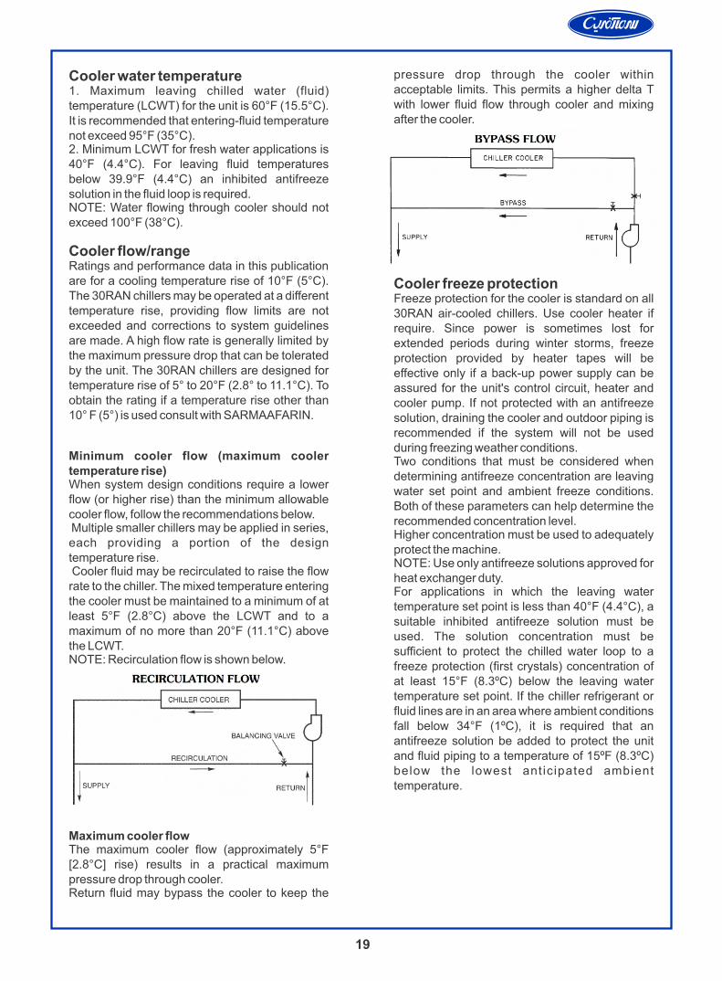
Maximum cooler flowThe maximum cooler flow (approximately 5°F [2.8°C] rise) results in a practical maximum pressure drop through cooler.Return fluid may bypass the cooler to keep the
pressure drop through the cooler within acceptable limits. This permits a higher delta T with lower fluid flow through cooler and mixing after the cooler.
Cooler freeze protectionFreeze protection for the cooler is standard on all 30RAN air-cooled chillers. Use cooler heater if require. Since power is sometimes lost for extended periods during winter storms, freeze protection provided by heater tapes will be effective only if a back-up power supply can be assured for the unit's control circuit, heater and cooler pump. If not protected with an antifreeze solution, draining the cooler and outdoor piping is recommended if the system will not be used during freezing weather conditions.Two conditions that must be considered when determining antifreeze concentration are leaving water set point and ambient freeze conditions. Both of these parameters can help determine the recommended concentration level.Higher concentration must be used to adequately protect the machine.NOTE: Use only antifreeze solutions approved for heat exchanger duty.For applications in which the leaving water temperature set point is less than 40°F (4.4°C), a suitable inhibited antifreeze solution must be used. The solution concentration must be sufficient to protect the chilled water loop to a freeze protection (first crystals) concentration of at least 15°F (8.3ºC) below the leaving water temperature set point. If the chiller refrigerant or fluid lines are in an area where ambient conditions fall below 34°F (1ºC), it is required that an antifreeze solution be added to protect the unit and fluid piping to a temperature of 15ºF (8.3ºC) below the lowest anticipated ambient temperature.
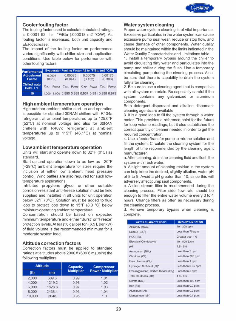
Cooler fouling factorThe fouling factor used to calculate tabulated ratings is 0.0001 ft2 hr °F/Btu (.000018 m2 °C/W). As fouling factor is increased, both unit capacity and EER decrease.The impact of the fouling factor on performance varies significantly with chiller size and application conditions. Use table below for performance with other fouling factors.
High ambient temperature operationHigh outdoor ambient chiller start-up and operation is possible for standard 30RAN chillers with R134a refrigerant at ambient temperatures up to 125.6°F (52°C) at nominal voltage and also for 30RAN chillers with R407c refrigerant at ambient temperatures up to 115°F (46.1°C) at nominal voltage.
Low ambient temperature operationUnits will start and operate down to 32°F (0°C) as standard.Start-up and operation down to as low as –20°F (–29°C) ambient temperature for sizes require the inclusion of either low ambient head pressure control. Wind baffles are also required for such low-temperature applications.Inhibited propylene glycol or other suitable corrosion-resistant anti-freeze solution must be field supplied and installed in all units for unit operation below 32°F (0°C). Solution must be added to fluid loop to protect loop down to 15°F (8.3 °C) below minimum operating ambient temperature.Concentration should be based on expected minimum temperature and either “Burst” or “Freeze” protection levels. At least 6 gal per ton (6.5 L per kW) of fluid volume is the recommended minimum for a moderate system load.
Altitude correction factorsCorrection factors must be applied to standard ratings at altitudes above 2000 ft (609.6 m) using the following multipliers:
Water system cleaningProper water system cleaning is of vital importance. Excessive particulates in the water system can cause excessive pump seal wear, reduce or stop flow, and cause damage of other components. Water quality should be maintained within the limits indicated in the Water Quality Characteristics and Limitations table.1. Install a temporary bypass around the chiller to avoid circulating dirty water and particulates into the pump and chiller during the flush. Use a temporary circulating pump during the cleaning process. Also, be sure that there is capability to drain the system fully after cleaning.2. Be sure to use a cleaning agent that is compatible with all system materials. Be especially careful if the system contains any galvanized or aluminum components.Both detergent-dispersant and alkaline dispersant cleaning agents are available.3. It is a good idea to fill the system through a water meter. This provides a reference point for the future for loop volume readings, but it also establishes the correct quantity of cleaner needed in order to get the required concentration.4. Use a feeder/transfer pump to mix the solution and fill the system. Circulate the cleaning system for the length of time recommended by the cleaning agent manufacturer.a. After cleaning, drain the cleaning fluid and flush the system with fresh water.b. A slight amount of cleaning residue in the system can help keep the desired, slightly alkaline, water pH of 8 to 9. Avoid a pH greater than 10, since this will adversely affect pump seal components.c. A side stream filter is recommended during the cleaning process. Filter side flow rate should be enough to filter the entire water volume every 3 to 4 hours. Change filters as often as necessary during the cleaning process.d. Remove temporary bypass when cleaning is complete.
20
Evaporator Fouling Factor ft2 hr °F/Btu (m2 °C/W)PerformanceAdjustment
Factor0.00175(0.308)
0.00075(0.132)
0.00025(0.044)
0.0001(0.018)
PowerChilled water
Delta T °F
1.000 1.000
Cap. PowerCap. PowerCap. PowerCap.
0.990 0.9780.8980.9910.9570.99810
CompressorPower Multiplier
CapacityMultiplier
Altitude
(ft) (m)
2,0004,0006,000
609.61219.21828.8
0.990.980.97
1.011.021.03
8,00010,000
2438.43048
0.960.95
1.041.0
WATER CHARACTERISTIC
Alkalinity (HCO )3-
2-Sulfate (So )4
2-HCO /So3- 4
Electrical Conductivity
pH
Ammonium (NH )3
-Chorides (Cl )
Free chlorine (Cl )2
Hydrogen Sulfide (H S)*2
Free (aggressive) Carbon Dioxide (Co )2
Total Hardness (dH)
Nitrate (No )3
Iron (Fe)
Aluminum (Al)
Manganese (Mn)
70 - 300 ppm
Less than 70 ppm
Greater than 1.0
10 - 500 S/cm
7.5 - 9.0
Less than 2 ppm
Less than 300 ppm
Less than 1 ppm
Less than 0.05 ppm
Less than 5 ppm
4.0 - 8.5
Less than 100 ppm
Less than 0.2 ppm
Less than 0.2 ppm
Less than 0.1 ppm
QUALITY LIMITATION
Sanaye Sarmaafarin Iran
شرکت صنایع سرما آفرین ایران(کریر ترموفریگ)
No. 194, W. Khorramshahr (Apadana) Ave., TEHRAN-15337, P. O. BOX: 13145-1799 Tel: 88762038 Fax: 88762033
سهروردي شمالی، خیابان خرمشهر، شماره 194، تهران - 15377، صندوق پستی: 1799-13145 تلفن: 88762038 فاکس: 88762033
Manufacturer reserves the right to discontinue or change at time, specifications of designs without notice and without incurring obliqations
www.sarmaafarin.com www.ssi.co.ir