
AIR COOLED LIQUID CHILLER - · PDF fileses without the prior agreement of Itelco-Clima or...
68
RLC AIR COOLED LIQUID CHILLER INSTALLATION, COMMISSIONING, OPERATION AND MAINTENANCE R134a RLC-A & RLC-A R/P/D R407C RLC-B GB Part No. 035B09025-0GB Subject to change without notice ALL RIGHTS RESERVED
Transcript of AIR COOLED LIQUID CHILLER - · PDF fileses without the prior agreement of Itelco-Clima or...

RLCAIR COOLED LIQUID CHILLER
INSTALLATION, COMMISSIONING,OPERATION AND MAINTENANCE
R134a RLC-A & RLC-A R/P/DR407C RLC-B
GBPart No. 035B09025-0GB
Subject to change without noticeALL RIGHTS RESERVED
1
1 SUPPLIER INFORMATION
1.1 Introduction 3
1.2 Warranty 3
1.3 Safety 3
1.4 Emergency Stops/Shutdown 4
1.5 About this Manual 4
1.6 Safety Labels 5
1.7 Material Safety Data 7
2 PRODUCT DESCRIPTION
2.1 Introduction 10
2.2 General Specification 10
2.3 Compressors 10
2.4 Refrigerant Circuits 11
2.5 Evaporators 11
2.6 Air Cooled Condensers 11
2.7 Heat Recovery Condensers 11
2.8 Power And Controls 12
2.9 “Chiller Control” 12
2.10 Accessories 13
2.11 Interface Board 13
2.12 Options 13
2.13 Theory Of Operation 14
3 TRANSPORTATION, HANDLING AND STORAGE
3.1 Inspection 15
3.2 Handling 15
3.3 Anchorage 16
3.4 Storage 16
4 INSTALLATION
4.1 Location 17
4.2 External Water System 17
4.3 Water Connections 20
4.4 Electrical Supplies 21
4.5 Electrical Connections 22
5 COMMISSIONING
5.1 Preliminary Checks 25
5.2 Starting 25
5.3 Performance Check 26
5.4 Customer Handover 26
6 OPERATION
6.1 Regulation and Control Logic 27
6.2 Compressor Starting Logic 27
6.3 Water Temperature Regulation (IN) 28
6.4 Water TemperatureRegulation (OUT) 28
6.5 Control Panel 31
6.6 Unit Starting 32
6.7 Set Point 33
6.8 Heat Recovery Operation 33
6.9 Alarm Display and Reset 33
6.10 Unit Shutdown 33
6.11 Electromechanical SafetyDevices 33
Table of Contents
7 MAINTENANCE
7.1 General Requirements 35
7.2 Daily Maintenance 35
7.3 Refrigerant Charge 36
7.4 Refrigerant Circuits 36
7.5 Compressors 36
7.6 Condenser Coils 37
7.7 Condenser Fans 37
7.8 Filter Drier 37
7.9 Sight Glass 37
7.10 Thermostatic Expansion Valve 38
7.11 Evaporator 38
8 TROUBLE SHOOTING 39
9 TECHNICAL DATA
9.1 Pressure Drop Graphs 41
9.2 Safety Switch Setting 43
9.3 Operational Limits 44
9.4 Physical Data 46
9.5 Total Unit Electrical Data 49
9.6 Compressor Electrical Data 50
9.7 Fan Electrical Data 51
9.8 Sound Power Levels 52
9.9 Dimension, Weight and Isolator Data 53
9.10 Piping and InstrumentationDiagrams 56
9.11 General Arrangements 60
10 SPARE PARTS
10.1 Recommended Spares 66
10.2 Recommended Compressor Oils 66
10.3 Wiring Diagrams 66
11 DE-COMMISSIONING, DISMANTLINGAND DISPOSAL
11.1 General 67
2

3
1 SUPPLIER INFORMATION
1.1 Introduction
RLC Series chillers are manufactured to the moststringent design and construction standards to en-sure high performance, reliability and adaptability toall types of air conditioning installations. The unit isintended for cooling water (and heating water in thecase of heat recovery chillers of those fitted with adesuperheater) and is not suitable for purposesother than those specified in this manual.
If the unit is used improperly, or for different purpo-ses without the prior agreement of Itelco-Clima ortheir agents, then such use would be outside thescope and may be unsafe.
This manual contains all the information requiredfor correct installation and commissioning of theunit, together with operation and maintenance in-structions. The manual should be read thoroughlybefore attempting to operate or service the unit.
With the exception of the operations detailed in thismanual, all installation, commissioning and mainte-nance tasks must be performed by suitably trainedand qualified personnel from an Authorised ServiceCentre.
The manufacturer is not liable for injury or damageresulting from incorrect installation/commissioningor operation, insufficient maintenance and/or failureto follow the procedures and instructions containedin this manual.
1.2 Warranty
The unit is supplied finished, tested and ready towork. The unit warranty will be void if any modifica-tion to the unit is carried out without written agree-ment of the manufacturer.
For warranty purposes, the following conditionsmust be satisfied:
■ The initial start of the unit must be carried out bytrained personnel from an Authorised ServiceCentre.
■ Maintenance must be carried out by properly trai-ned personnel.
■ Only genuine spare parts must be used.
■ All the scheduled maintenance operations detai-led in this manual must be performed at the spe-cified times.
Failure to satisfy any of these conditions will auto-matically void the warranty.
1.3 Safety
The installation of the unit must be carried outaccording to the Machinery Safety Directive(CEE 98/37), to the Low Voltage Directive(73/23/EEC), to the Electromagnetic Interferen-ce Directive (89/336/EEC) as modified by Direc-tive (92/31/EEC) and according to normal rulesfor technical matters prescribed by the applica-ble country regulations. Do not operate the unitbefore having observed all the above.
The unit must be earthed and no instal-lation or maintenance work should beattempted on the electrical equipmentwithout first switching off and isolatingthe main power supply and any controlsupplies.
Failure to observance of the above safety measu-res may result in fire or electrocution should a short-circuit occur.
WARNING
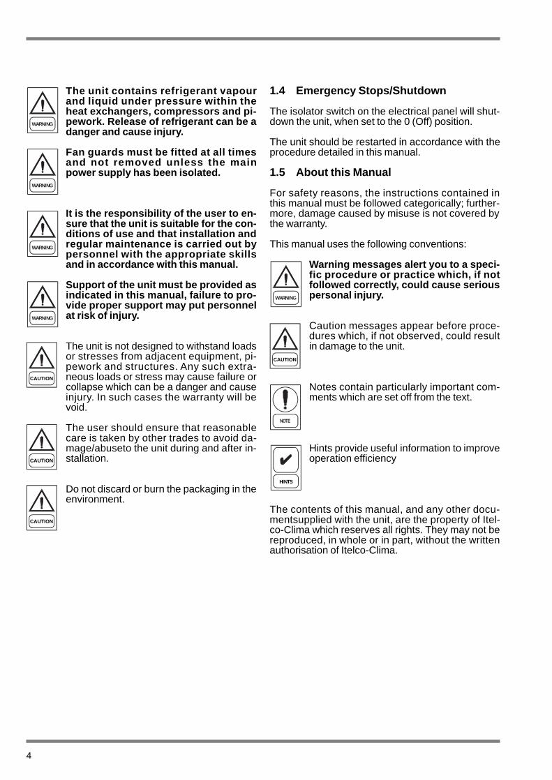
The unit contains refrigerant vapourand liquid under pressure within theheat exchangers, compressors and pi-pework. Release of refrigerant can be adanger and cause injury.
Fan guards must be fitted at all timesand not removed unless the mainpower supply has been isolated.
It is the responsibility of the user to en-sure that the unit is suitable for the con-ditions of use and that installation andregular maintenance is carried out bypersonnel with the appropriate skillsand in accordance with this manual.
Support of the unit must be provided asindicated in this manual, failure to pro-vide proper support may put personnelat risk of injury.
The unit is not designed to withstand loadsor stresses from adjacent equipment, pi-pework and structures. Any such extra-neous loads or stress may cause failure orcollapse which can be a danger and causeinjury. In such cases the warranty will bevoid.
The user should ensure that reasonablecare is taken by other trades to avoid da-mage/abuseto the unit during and after in-stallation.
Do not discard or burn the packaging in theenvironment.
1.4 Emergency Stops/Shutdown
The isolator switch on the electrical panel will shut-down the unit, when set to the 0 (Off) position.
The unit should be restarted in accordance with theprocedure detailed in this manual.
1.5 About this Manual
For safety reasons, the instructions contained inthis manual must be followed categorically; further-more, damage caused by misuse is not covered bythe warranty.
This manual uses the following conventions:
Warning messages alert you to a speci-fic procedure or practice which, if notfollowed correctly, could cause seriouspersonal injury.
Caution messages appear before proce-dures which, if not observed, could resultin damage to the unit.
Notes contain particularly important com-ments which are set off from the text.
Hints provide useful information to improveoperation efficiency
The contents of this manual, and any other docu-mentsupplied with the unit, are the property of Itel-co-Clima which reserves all rights. They may not bereproduced, in whole or in part, without the writtenauthorisation of Itelco-Clima.
4
WARNING
WARNING
WARNING
WARNING
WARNING
CAUTION
CAUTION
CAUTION
HINTS
CAUTION

5
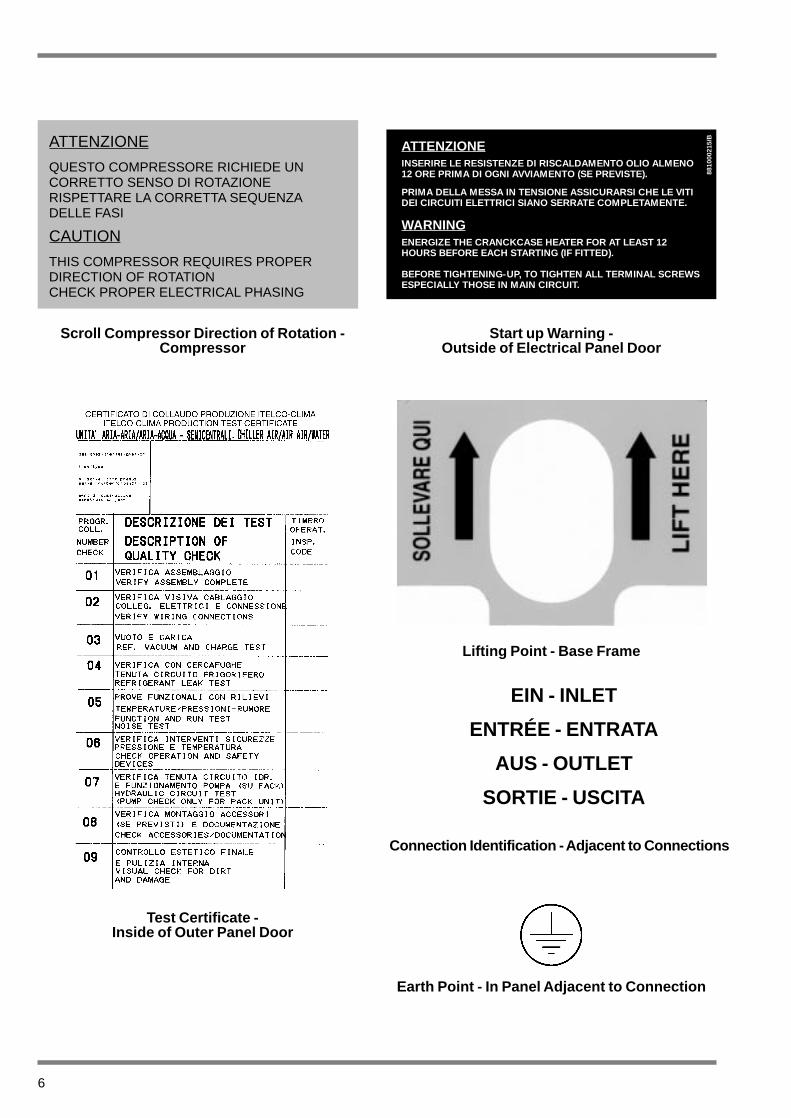
1.6 Safety Labels
The following labels are fitted to each unit in the lo-cations stated:
Unit Identification -Inside of Outer Panel Door
Refrigerant Identification - Outside Panel Door
Electrical Warning -Adjacent to Isolator Switch
Centre of Gravity - Base Frame
TENERE SU QUESTA LINEAGANCIO DI SOLLEVAMENTO
KEEP LIFT HOOKON THIS LINE
6
Earth Point - In Panel Adjacent to Connection
Scroll Compressor Direction of Rotation -Compressor
Start up Warning -Outside of Electrical Panel Door
Test Certificate -Inside of Outer Panel Door
Lifting Point - Base Frame
Connection Identification - Adjacent to Connections
ATTENZIONE
QUESTO COMPRESSORE RICHIEDE UNCORRETTO SENSO DI ROTAZIONERISPETTARE LA CORRETTA SEQUENZADELLE FASI
CAUTION
THIS COMPRESSOR REQUIRES PROPERDIRECTION OF ROTATIONCHECK PROPER ELECTRICAL PHASING
ATTENZIONEINSERIRE LE RESISTENZE DI RISCALDAMENTO OLIO ALMENO12 ORE PRIMA DI OGNI AVVIAMENTO (SE PREVISTE).
PRIMA DELLA MESSA IN TENSIONE ASSICURARSI CHE LE VITIDEI CIRCUITI ELETTRICI SIANO SERRATE COMPLETAMENTE.
WARNINGENERGIZE THE CRANCKCASE HEATER FOR AT LEAST 12HOURS BEFORE EACH STARTING (IF FITTED).
BEFORE TIGHTENING-UP, TO TIGHTEN ALL TERMINAL SCREWSESPECIALLY THOSE IN MAIN CIRCUIT.
8810
0021
5/B
EIN - INLET
ENTRÉE - ENTRATA
AUS - OUTLET
SORTIE - USCITA
7
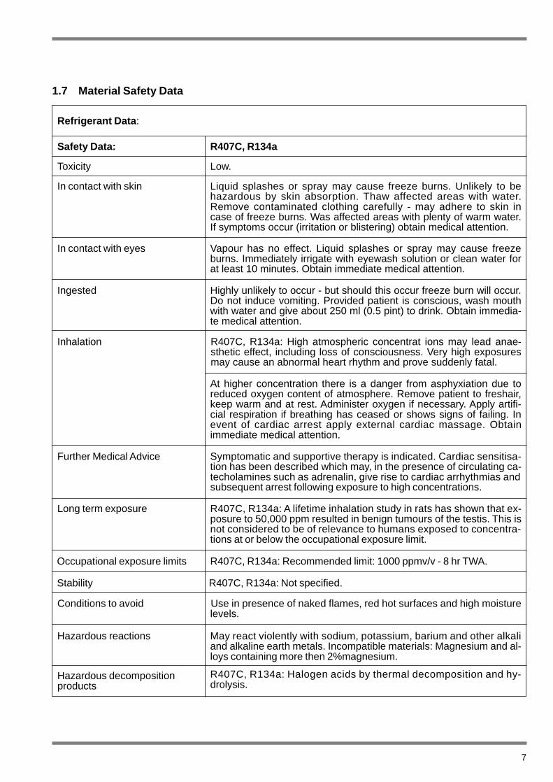
1.7 Material Safety Data
Refrigerant Data :
Safety Data: R407C, R134a
Toxicity Low.
In contact with skin Liquid splashes or spray may cause freeze burns. Unlikely to behazardous by skin absorption. Thaw affected areas with water.Remove contaminated clothing carefully - may adhere to skin incase of freeze burns. Was affected areas with plenty of warm water.If symptoms occur (irritation or blistering) obtain medical attention.
In contact with eyes
Ingested
Inhalation
Further Medical Advice
Long term exposure
Vapour has no effect. Liquid splashes or spray may cause freezeburns. Immediately irrigate with eyewash solution or clean water forat least 10 minutes. Obtain immediate medical attention.
Highly unlikely to occur - but should this occur freeze burn will occur.Do not induce vomiting. Provided patient is conscious, wash mouthwith water and give about 250 ml (0.5 pint) to drink. Obtain immedia-te medical attention.
R407C, R134a: High atmospheric concentrat ions may lead anae-sthetic effect, including loss of consciousness. Very high exposuresmay cause an abnormal heart rhythm and prove suddenly fatal.
At higher concentration there is a danger from asphyxiation due toreduced oxygen content of atmosphere. Remove patient to freshair,keep warm and at rest. Administer oxygen if necessary. Apply artifi-cial respiration if breathing has ceased or shows signs of failing. Inevent of cardiac arrest apply external cardiac massage. Obtainimmediate medical attention.
Symptomatic and supportive therapy is indicated. Cardiac sensitisa-tion has been described which may, in the presence of circulating ca-techolamines such as adrenalin, give rise to cardiac arrhythmias andsubsequent arrest following exposure to high concentrations.
R407C, R134a: A lifetime inhalation study in rats has shown that ex-posure to 50,000 ppm resulted in benign tumours of the testis. This isnot considered to be of relevance to humans exposed to concentra-tions at or below the occupational exposure limit.
Occupational exposure limits
Stability R407C, R134a: Not specified.
R407C, R134a: Recommended limit: 1000 ppmv/v - 8 hr TWA.
Conditions to avoid Use in presence of naked flames, red hot surfaces and high moisturelevels.
Hazardous reactions May react violently with sodium, potassium, barium and other alkaliand alkaline earth metals. Incompatible materials: Magnesium and al-loys containing more then 2%magnesium.
Hazardous decomposition products
R407C, R134a: Halogen acids by thermal decomposition and hy-drolysis.
8
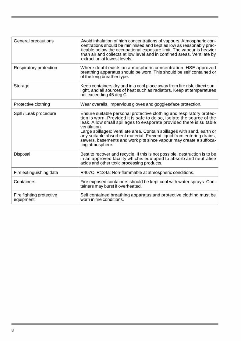
General precautions
Respiratory protection
Storage
Protective clothing
Spill / Leak procedure
Disposal
Fire extinguishing data
Containers
Fire fighting protective equipment
Where doubt exists on atmospheric concentration, HSE approvedbreathing apparatus should be worn. This should be self contained orof the long breather type.
Keep containers dry and in a cool place away from fire risk, direct sun-light, and all sources of heat such as radiators. Keep at temperaturesnot exceeding 45 deg C.
Wear overalls, impervious gloves and goggles/face protection.
Ensure suitable personal protective clothing and respiratory protec-tion is worn. Provided it is safe to do so, isolate the source of theleak. Allow small spillages to evaporate provided there is suitableventilation.Large spillages: Ventilate area. Contain spillages with sand, earth orany suitable absorbent material. Prevent liquid from entering drains,sewers, basements and work pits since vapour may create a suffoca-ting atmosphere.
Best to recover and recycle. If this is not possible, destruction is to bein an approved facility whichis equipped to absorb and neutraliseacids and other toxic processing products.
R407C. R134a: Non-flammable at atmospheric conditions.
Self contained breathing apparatus and protective clothing must beworn in fire conditions.
Fire exposed containers should be kept cool with water sprays. Con-tainers may burst if overheated.
Avoid inhalation of high concentrations of vapours. Atmospheric con-centrations should be minimised and kept as low as reasonably prac-ticable below the occupational exposure limit. The vapour is heavierthan air and collects at low level and in confined areas. Ventilate byextraction at lowest levels.
9
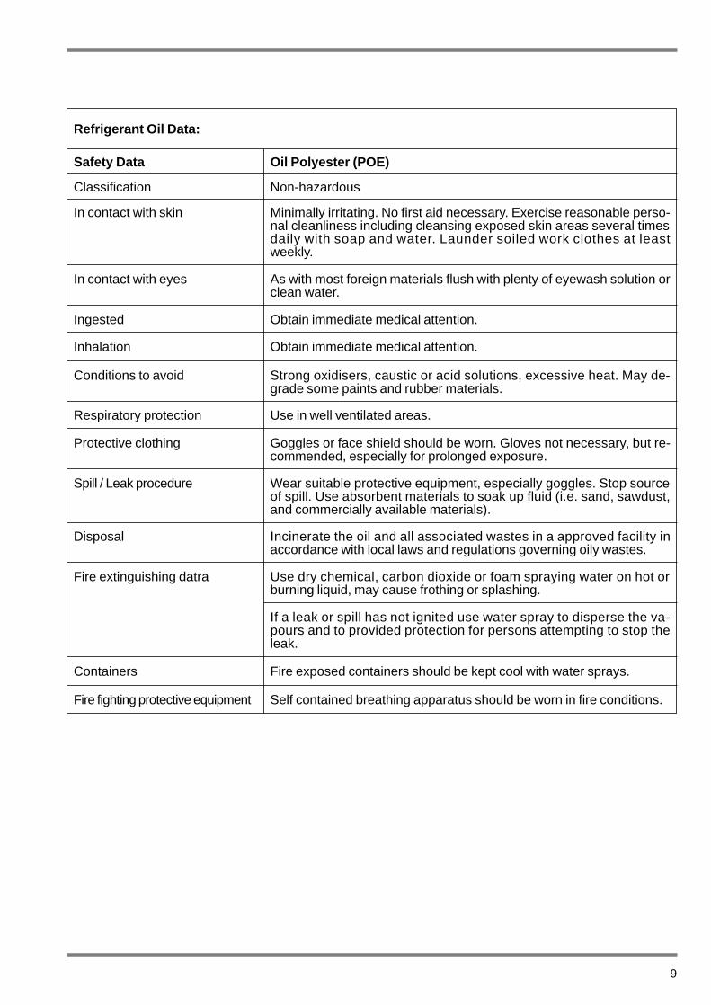
Refrigerant Oil Data:
Safety Data Oil Polyester (POE)
Classification
In contact with skin
In contact with eyes
Ingested
Inhalation
Conditions to avoid
Respiratory protection
Protective clothing
Spill / Leak procedure
Disposal
Fire extinguishing datra
Containers
Fire fighting protective equipment
Non-hazardous
Minimally irritating. No first aid necessary. Exercise reasonable perso-nal cleanliness including cleansing exposed skin areas several timesdaily with soap and water. Launder soiled work clothes at leastweekly.
As with most foreign materials flush with plenty of eyewash solution orclean water.
Obtain immediate medical attention.
Obtain immediate medical attention.
Strong oxidisers, caustic or acid solutions, excessive heat. May de-grade some paints and rubber materials.
Use in well ventilated areas.
Goggles or face shield should be worn. Gloves not necessary, but re-commended, especially for prolonged exposure.
Wear suitable protective equipment, especially goggles. Stop sourceof spill. Use absorbent materials to soak up fluid (i.e. sand, sawdust,and commercially available materials).
Incinerate the oil and all associated wastes in a approved facility inaccordance with local laws and regulations governing oily wastes.
Use dry chemical, carbon dioxide or foam spraying water on hot orburning liquid, may cause frothing or splashing.
If a leak or spill has not ignited use water spray to disperse the va-pours and to provided protection for persons attempting to stop theleak.
Fire exposed containers should be kept cool with water sprays.
Self contained breathing apparatus should be worn in fire conditions.
10
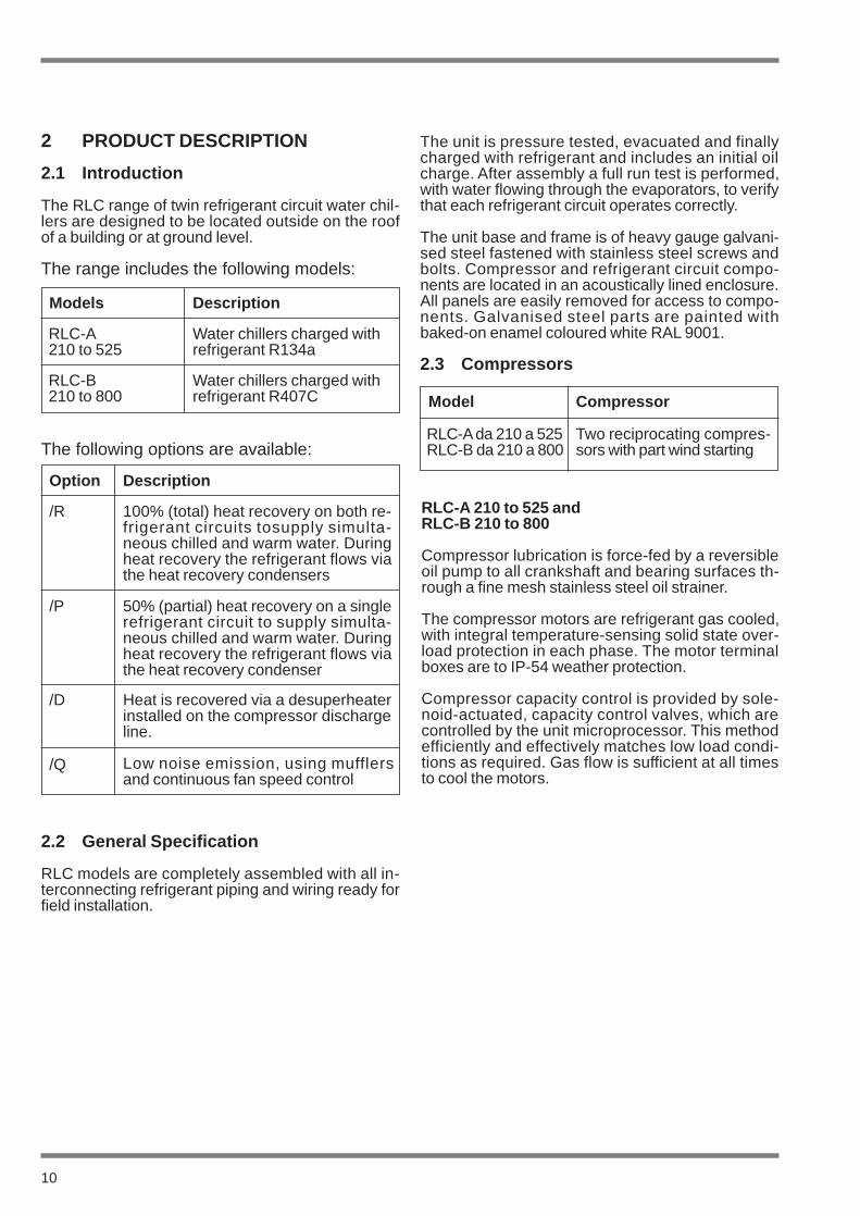
2 PRODUCT DESCRIPTION
2.1 Introduction
The RLC range of twin refrigerant circuit water chil-lers are designed to be located outside on the roofof a building or at ground level.
The range includes the following models:
The unit is pressure tested, evacuated and finallycharged with refrigerant and includes an initial oilcharge. After assembly a full run test is performed,with water flowing through the evaporators, to verifythat each refrigerant circuit operates correctly.
The unit base and frame is of heavy gauge galvani-sed steel fastened with stainless steel screws andbolts. Compressor and refrigerant circuit compo-nents are located in an acoustically lined enclosure.All panels are easily removed for access to compo-nents. Galvanised steel parts are painted withbaked-on enamel coloured white RAL 9001.
2.3 Compressors
Models Description
RLC-A210 to 525
Water chillers charged withrefrigerant R134a
RLC-B 210 to 800
Water chillers charged withrefrigerant R407C
The following options are available:
Option Description
/R 100% (total) heat recovery on both re-frigerant circuits tosupply simulta-neous chilled and warm water. Duringheat recovery the refrigerant flows viathe heat recovery condensers
/P 50% (partial) heat recovery on a singlerefrigerant circuit to supply simulta-neous chilled and warm water. Duringheat recovery the refrigerant flows viathe heat recovery condenser
/D Heat is recovered via a desuperheaterinstalled on the compressor dischargeline.
/Q Low noise emission, using mufflersand continuous fan speed control
2.2 General Specification
RLC models are completely assembled with all in-terconnecting refrigerant piping and wiring ready forfield installation.
Model
RLC-Ada 210 a 525RLC-B da 210 a 800
Compressor
Two reciprocating compres-sors with part wind starting
RLC-A 210 to 525 andRLC-B 210 to 800
Compressor lubrication is force-fed by a reversibleoil pump to all crankshaft and bearing surfaces th-rough a fine mesh stainless steel oil strainer.
The compressor motors are refrigerant gas cooled,with integral temperature-sensing solid state over-load protection in each phase. The motor terminalboxes are to IP-54 weather protection.
Compressor capacity control is provided by sole-noid-actuated, capacity control valves, which arecontrolled by the unit microprocessor. This methodefficiently and effectively matches low load condi-tions as required. Gas flow is sufficient at all timesto cool the motors.
11
2.4 Refrigerant Circuits
Two complete refrigerant circuits are supplied oneach unit. All piping is ACR copper, with brazedjoints. Refrigerant circuits include: a service valvefor refrigerant charging, suction discharge and li-quid line isolating valves, sight glass with moistureindicator, thermal expansion valve with externalequaliser. Solenoid valve, filter drier and differentialoil pressure switch on sizes 210 to 800. High andlow pressure switches and safety valves on sizes300 to 800.
2.5 Evaporators
RLC-A and RLC-B models 210 upwards each havea single steel shell and copper tube evaporator.
The dual-circuit evaporator is a direct-expansion ty-pe, with the refrigerant in the tubes, which are for-med in a hair-pin configuration, and chilled liquidflowing through the baffled shell. The evaporator iscovered with flexible, closed-cell, foam insulation.
Water connection to the evaporator is via threadedconnections on models 210 to 360 and victualic ty-pe on models 400 upwards.
All evaporators have a heating element controlledby a thermostat for frost protection to -10°C. Watervent and drain connections are included on all eva-porators.
The evaporator design working pressure on the wa-ter side is 10 bar g and on the refrigerant side 25bar g.
2.6 Air Cooled Condensers
The condenser coils are seamless copper tubes,arranged in staggered rows, mechanically expan-ded into corrugated aluminium fins. Integral sub-cooling is included. The design working pressure ofthe coil is 28 bar g.
The condenser fans are direct drive with aluminiumaerofoil blades. Each fan has a painted galvanisedsteel protection guard.
The three phase totally enclosed fan motors are toIP-54 weather protection and have thermocontactprotection embedded in their windings.
2.7 Heat Recovery Condensers
The heat recovery condensers are cleanable shelland tube type with seamless high pressure shelland external finned copper tubes rolled into tubesheets. The condenser shell is factory insulatedwith flexible closed cell insulation and has a heatermat for antifreeze protection down to -20°C.
The design working pressure is 25 bar g on the re-frigerant side and 10 bar g on the water side.
Full heat recovery units have two heat recoverycondensers and partial heat recovery units haveone condenser. All heat recovery units are equip-ped with cooling-heat recovery mode change-overvalve(s) and controller(s). A factory wired controlsensor, not including sensor pocket, is provided forfield installation.
12
2.8 Power And Controls
All units are equipped with a “Chiller Control” micro-processor control and management system.
All controls and motor starting equipment neces-sary for unit operation are factory wired and tested.
Power and control components are separated andaccessed via individual doors. The power sectionhas a door interlocked isolator. The total enclosureis fitted with a second upward opening door. Thepanel is designed to IP-54 weather protection.
The power compartment contains:
■ General switch.
■ Main isolator, compressor contactors and fuses,fan contactors and fuses.
The control compartment contains:
■ Anti-frost thermostat; auxiliaries transformer, fu-ses and relays.
■ The “Chiller Control” microcomputer keypad anddisplay, mounted in the control section door.
2.9 Chiller Control
The “Chiller Control” unit consists of an expandableinterface board and a control unit.
The expandable interface board monitors inputsand provides control outputs as follows:
■ Digital inputs, such as alarms and commands.
■ Analog inputs, such as temperature and pressuremeasurements.
■ Digital outputs for control relay and remote con-trol switch operation.
The control unit implements the following logic:
■ LED and visual display of unit alarms and unitoperation.
■ Compressor start-up logic (part-winding and cutout), power adjustment on 2 or 4 steps.
■ Display of compressor working hours and evapo-rator temperature.
■ Anti-cycling and anti-start-up surge timers.
■ Automatic compressor lead/lag start-up sequen-ce.
■ Fan cut out.
Management of set points and parametric data:
■ User level - The machine operator can adjust da-ta at the keyboard with the ‘SET’, ‘+’ and ‘-’ keys.
■ Service Level - System password access forauthorised Service personnel.
The display panel has keypad type buttons identi-fied by symbols, colour coded to Eurovent stan-dards, and LED’s to display function status:
■ Green indicates Normal operation
■ Yellow indicates Caution
■ Red indicates Stop

13
2.10 Accessories
Flow Switch
Supplied loose for field installation by contractor.
Anti-vibration Mounts
Open spring isolator mounts with fixing down holes,supplied loose for field installation by contractor.
Improved Capacity Control
Six or eight step control instead of standard fourstep control for semi-hermetic compressor models.
Fan-speed Control
Maintains constant condensing temperature, duringoperation in low ambient conditions.
2.11 Interface Board
An optional communications interface enables theunit to be controlled and managed from a local sta-tion via RS232 up to 500m, or via modem and a te-lephone line.Remote management and control can therefore bemet by integrating twith a Building Management Sy-stem.
Nomenclature
2.12 Options
Condenser Coil-fin Protection
Painted galvanised steel guards mounted on theexterior of the unit.
Air Cooled Condenser Options
Copper fins or vinyl coated fins.
Gauge Kit
Factory fitted mechanical dial gauges for suctionand discharge pressure indication of each refrigera-tion circuit.
Extra Temperature and Pressure Sensors
To display compressor suction and discharge pres-sures and evaporation temperature of each refrige-ration circuit.
Time Programme Board
Factory mounted to programme set point hours perday (Maximum of four different set points over 24hours per day and 5 days). Also implements chilleron/off schedule. Generally used with ice storage sy-stems.
REFRIGERATOR
LARGE CAPACITY
COOLING ONLY
COMMERCIAL USE
SIZE
DESUPERHEATER
PARTIAL RECOVERY
TOTAL RECOVERY
REFRIGERANT
A = R134aB = R407c
R L C - 360 A / R / P / D

RLC-A & RLC-B
2.13 Theory Of Operation
Cooling Mode
Low pressure liquid refrigerant enters the cooler(Evaporator) and is evaporated and superheatedby the heat energy absorbed fromthe chilled waterpassing through the cooler shell. Low pressure va-pour enters the compressor where pressure andsuperheat are increased. Heat is rejected via the aircooled condenser coil and fans. The fully conden-sed and subcooled liquid refrigerant then enters theexpansion valve where pressure reduction andfurther cooling takes place before returning to thecooler.
RLC-A /R
14
RLC-A /P
Heat Recovery Mode
During heat recovery operation the refrigerant pas-ses to the water cooled condenser instead of the aircooled condenser. The high pressure superheatedrefrigerant vapour enters the condenser shell, whe-reheat is rejected to thewarm water in the tubes,and is condensed. High pressure liquid refrigerantthen passes through the expansion valve, wherepressure reduction and cooling takes place, beforereturning to the cooler. Excess heat is rejectedattheair cooledcondenser.
RLC-A /DRLC-B/D (to Model 400)
CONDENSERCOIL
COOLER
LP VAPOUR HP LIQUID HP VAPOUR LP LIQUID
CONDENSERCOIL
COOLERHEATRECOVERYCONDENSER
LP VAPOUR HP LIQUID HP VAPOUR LP LIQUID
WITH 50%HEAT RECOVERY
WITH 100%HEAT RECOVERYCONDENSER
COIL
CONDENSERCOIL
HEATRECOVERYCONDENSER
LP VAPOUR HD LIQUID HP VAPOUR LP LIQUID
HEATRECOVERYCONDENSER
DESUPERHEATER
CONDENSERCOILS
DESUPERHEATER
LP VAPOUR HP LIQUID HP VAPOUR LP LIQUID
COOLER
WITH DESUPERHEATERS

15
3 TRANSPORTATION, HANDLINGAND STORAGE
RLC series chillers are supplied fully assembled,(with the exception of the rubber vibration padssupplied with the unit) which are installed on site.Units are pre-charged with refrigerant and oil in thecorrect quantity required for operation.
3.1 Inspection
Immediately upon receiving the unit, it should be in-spected for possible damage which may have oc-curred during transit as goods are shipped ex-works at purchaser’s risk. In addition, ensure thatall ordered components have been received. If any damage is evident, it should be noted on thecarrier’s freight bill and a claim entered in accordan-ce with the advice note instructions. If the damageis other than superficial, immediately advise yourlocal Itelco-Clima representative.
Itelco-Clima accepts no responsibility for shippingdamage, even in cases where the factory has ar-ranged for shipping.
3.2 Handling
RLC series chillers are designed to be lifted usinglifting lugs and cables. A spreader bar or frameshould be used with the cables, to avoid crushingthe unit.
Before moving the unit ensure that the installationsite is suitable to receive the unit and to support itsweight and mechanical impact.
During handling, avoid touching sharp parts (forexample coil fins).
Never move the machine on rollers or liftthe machine using a fork lift truck.
Proceed as follows to lift and move the machine:
■ Insert and secure the lifting lugs through themarked holes in the base frame.
■ Attach the cables to the lifting lugs.
■ Insert a spreader bar or frame between the ca-bles, vertical to the unit’s centre of gravity.
■ Attach the crane hook at the unit’s centre of gra-vity.
■ Cable length shall be such that they do not forman angle of less than 45 degrees to the horizontalwhen under tension.
International Lifting Lugs
L > Unit Width
Care should be taken to avoid damagingthe side-mounted coil fins and panellingwhen lifting and moving the unit to the in-stallation site.
The sides of the unit should be protectedwith stiff cardboard or plywood.
L
CAUTION
CAUTION
CAUTION
Do not remove the protective plastic wrap-ping and the coil protectors, which preventdirt, dust and other foreign matter from en-tering the fan grilles or damaging the exter-nal surfaces, until the unit is ready for ope-ration.
3.3 Anchorage
RLC Series chillers are provided with 18 mm dia-meter holes in the base frame for retaining thespring damper mounts if required.
It is not necessary to anchor theunit to foundations,except in areas of high risk of earthquake, or wherethe unit is located at high level on a steel mountingframe.
3.4 Storage
If the unit is to be stored prior to installation, certainprecautions should be taken to prevent damage,corrosion or deterioration:
■ Ensure that all openings, such as water connec-tions, are securely capped or sealed.
■ Do not store where exposed to ambient air tem-peratures exceeding 45°C for R134a or 42°C forR407c units, preferably out of direct sunlight.
■ The finned heat exchangers should remain cove-red to protect the fins from potential corrosion,particularly where building work is in progress.
■ Store the unit in a location where minimum acti-vity is likely to take place in order to limit the riskof accidental damage.
■ Do not steamclean the unit.
■ Remove the keys necessary to gain access tothe control panel and deposit them with a respon-sible person on site.
Periodic visual examination during storage is re-commended.
16
CAUTION

4 INSTALLATION
4.1 Location
Before installing the unit, make surethat the building structure and/ormounting surface can support the unitweight. Overall weights and weight di-stribution is detailed in Section 9.
The unit has been designed for floor mounting inoutside locations. Rubber anti-vibration pads aresupplied as standard and they must be positionedcentrally, underneath each of the supporting plates.
When the unit is to be installed on the ground, aconcrete slab must be provided to ensure uniformweight distribution.
Special mounts are not normally required. Howe-ver, if the unit is to be installed directly above inha-bited rooms, it is advisable to set the unit on springdamper mounts (supplied as accessories, refer toSection 9) to minimise the vibrations transmitted tothe structure.
The following factors must be considered when se-lecting a location for the unit:
■ The units longitudinal axis should be parallel toprevailing winds to ensure balanced air flow overthe condenser coils.
■ The unit should not besited downwind of boilerflues.
■ The unit should not be sited downwind of sourcesof grease-laden air such as extractor vents forlarge kitchens. In such cases, accumulated grea-se on the condenser fins can trap air-borne con-taminants, thus leading to rapid soiling or clog-ging.
■ The unit should not be sited in areas exposed toheavy snowfall.
■ The unit should not be sited in areas exposed toflooding or beneath downpipes, etc.
■ The unit should not be sited in air wells,courtyards or other restricted spaces where noi-se would be reverberated off the walls, or whereair expelled by fans could be channelled back tocondenser inlets.
■ The installation position should ensure adequateclearances for air circulation and maintenance,refer to Section 9 for details.
4.2 External Water System
The external water hydraulic circuit mustensure constant water flow to the evapora-tor under all operating or adjustment con-ditions.
The external water system should consist of the fol-lowing:
■ A circulation pump providing sufficient output andhydraulic head.
■ To ensure that repetitive starts of compressors isavoided, which can cause damages, the primarysystem water content should be no less than 10litres per kW of cooling capacity. If the total volu-me in primary system pipework and evaporator isinsufficient, an insulated buffer tank should be in-stalled.
■ A diaphragm-type expansion tank with safety val-ve outlet which must be visible.
The tank should be sized to accommodatea 2% increase in total fluid volume in thesystem (evaporator, lines, user circuits andwater reservoir where provided). The Ex-pansion tank need not necessarily be insu-lated, as water does not normally circulatetherein.
■ A flow switch to deactivate the unit when water isnot circulating.
The flow switch must be connected in se-ries with external interlocks as shown onwiring diagram in control panel.
17
WARNING
CAUTION
CAUTION
Follow the manufacturer’s instructions careful-ly when installing the flow switch.
In general, the flow switch should be installed onthe pump delivery, upstream of the unit, on a hori-zontal pipe run of at least 10 pipe diameters fromany bend, valve or other item which could interferewith water flow upstream or downstream of the flowswitch.
A Normally Open differential pressure switch maybe installed instead of the flow switch. The pressureswitch senses water pressure drop across the eva-porator.
In addition:
■ Install air vent valves at the highest points of thelines.
■ Install shutoff valves on the evaporator and heatrecovery condenser inlet and outlet water lines.
■ Provide suitable drainage points (with plugs,cocks etc.) at the lowest points of the lines.
■ Install a valved by-pass around the evaporator.
■ Insulate the pipework to prevent heat loss.
■ A filter/strainer located on the suction side of theevaporator or heat recovery condenser.
■ A water flow measuring device.
18

Key
I Pressure gauge tappingGA Flexible connectionsT ThermometerS Gate valvesR Drain tapF StrainerFl Flow switch
Before filling the system, ensure that it isfree from foreign matter, sand, stones, rustflakes, solder, slag or other materials whi-ch could damage the evaporator.
It is advisable to by-pass the unit when flushing outthe l ines. A strainer screen must be installedupstream of the chiller.
Water used to fill the circuit may have to betreated to ensure that the PH value is cor-rect.
Standard evaporators provided on RLC units aredesigned to chill mixtures of water and ethylene gly-col with a corrosion-inhibiting additive down to–10°C.
The amount of ethylene glycol to be added is as fol-lows.
Amounts are shown as a percentage by weight ofthe circuit design water content:
operation from + 5 to 0 °C : 20%
operation from 0 to -5 °C : 30%
operation from -5 to -10 °C : 40%
19
Typical Connection Diagram
CAUTION
UNIT EXTERNAL WATER SYSTEM
FLOW SWITCH INSTALLATION
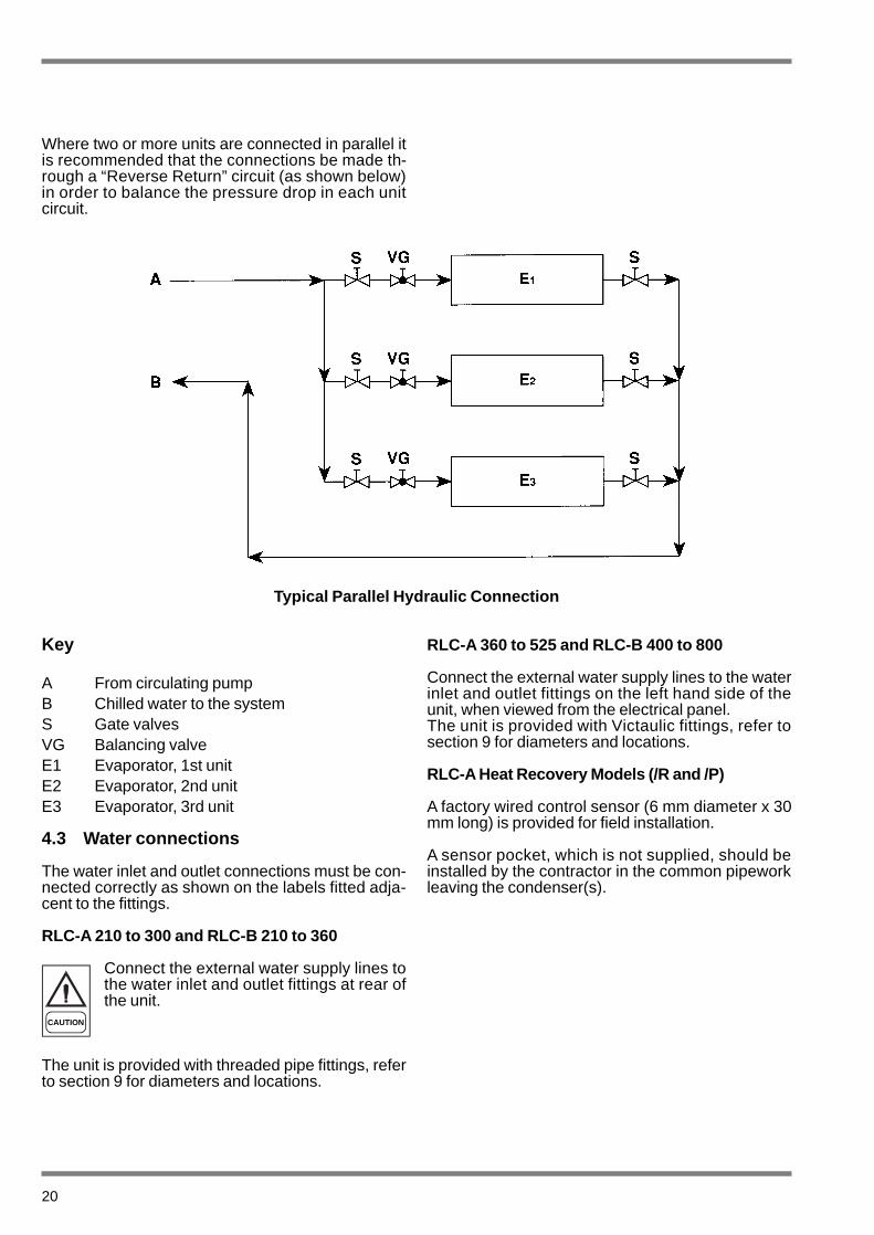
Where two or more units are connected in parallel itis recommended that the connections be made th-rough a “Reverse Return” circuit (as shown below)in order to balance the pressure drop in each unitcircuit.
Key
A From circulating pumpB Chilled water to the systemS Gate valvesVG Balancing valveE1 Evaporator, 1st unitE2 Evaporator, 2nd unitE3 Evaporator, 3rd unit
4.3 Water connections
The water inlet and outlet connections must be con-nected correctly as shown on the labels fitted adja-cent to the fittings.
RLC-A 210 to 300 and RLC-B 210 to 360
Connect the external water supply lines tothe water inlet and outlet fittings at rear ofthe unit.
The unit is provided with threaded pipe fittings, referto section 9 for diameters and locations.
RLC-A 360 to 525 and RLC-B 400 to 800
Connect the external water supply lines to the waterinlet and outlet fittings on the left hand side of theunit, when viewed from the electrical panel.The unit is provided with Victaulic fittings, refer tosection 9 for diameters and locations.
RLC-A Heat Recovery Models (/R and /P)
A factory wired control sensor (6 mm diameter x 30mm long) is provided for field installation.
A sensor pocket, which is not supplied, should beinstalled by the contractor in the common pipeworkleaving the condenser(s).
20
Typical Parallel Hydraulic Connection
CAUTION
21
4.4 Electrical Supplies
Ensure that the power supply is offbefore working on the electrical sy-stem.
The unit must be provided with an earthconnection.
It is the installers responsibility to ensurethat all external wiring complies with appli-cable safety regulations.
The Manufacturer is not responsible for injuryor damage of any kind resulting from failure toobserve these precautions.
The unit complies with EN 60 204-1.
The following connections are required:
■ One three-phase line and earth for the power cir-cuit supply.
The electrical distribution system must be able tosupply all the unit power, refer to Section 9.
The disconnect switches and circuit breakers mustbe sized to handle the unit starting current, refer tosection 9.
Supply and isolating devices shall be designed sothat the lines are fully independent.
Magnetic thermal differential breakers are recom-mended, to prevent damage due to electrical phaseloss.
Power supplies to the compressors and the fansare through contactors controlled by the control pa-nel.
Each motor is provided with an internal thermaloverload cut-out and external fuses.
Supply cables should be routed through the cableentries on the unit front and enter the electrical pa-nel through a hole at the bottom of the panel.
WARNING
WARNING
CAUTION
4.5 Electrical Connections
The installation of the unit on the final site mustbe carried out according to the Machinery Sa-fety directive (98/37/EC), to the Low Voltage Di-rective (73/23/EEC), to the Electromagnetic In-terference directive (89/336/EEC) and accordingto normal rules for technical matters prescribedby the applicable country regulations. Do notoperate the unit before having observed all theabove. Supply lines shall consist of insulatedcopper conductors sized for maximum currentdraw.
Terminal connections should be made in accordan-ce with the connection diagram in this manual andthe diagram supplied with the unit.
Before connecting the supply lines, checkthat the mains voltage is within the rangeshown in the Electrical Data in Section 9.
For the 3 phase power supply, also check that thephase unbalance does not exceed 2%. The checkis performed by measuring the difference betweenthe voltage of each phase pair and the averagemains voltage during operation. The maximummeasured difference (unbalance) shall not exceed2% of the average voltage.
If the unbalance is unacceptable, the electricitysupply company must be asked to correct the fault.
Supplying the unit with a line whose unba-lance exceeds the specified value will au-tomatically void the warranty.
22
CAUTION
CAUTION
23
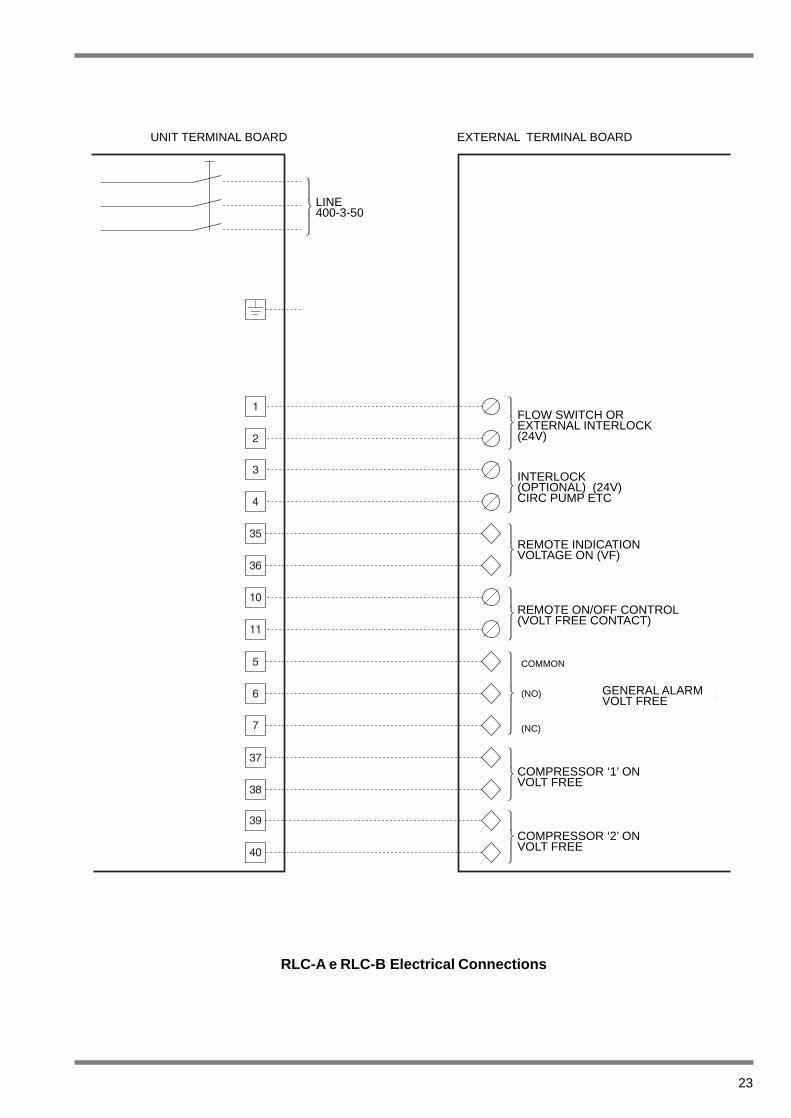
RLC-A e RLC-B Electrical Connections
MORSETTIERA DELL'UNITÁ MORSETTIERA ESTERNAUNIT TERMINAL BOARD EXTERNAL TERMINAL BOARD
LINE400-3-50
FLOW SWITCH OREXTERNAL INTERLOCK(24V)
INTERLOCK(OPTIONAL) (24V)CIRC PUMP ETC
REMOTE INDICATIONVOLTAGE ON (VF)
REMOTE ON/OFF CONTROL(VOLT FREE CONTACT)
COMPRESSOR ‘1’ ONVOLT FREE
COMPRESSOR ‘2’ ONVOLT FREE
GENERAL ALARMVOLT FREE
COMMON
(NO)
(NC)

24
RLC-A, RLC-B with Heat Recovery, Electrical Connections
MORSETTIERA DELL'UNITÁ MORSETTIERA ESTERNAUNIT TERMINAL BOARD EXTERNAL TERMINAL BOARD
LINE400-3-50
FLOW SWITCH OREXTERNAL INTERLOCK(24V)
INTERLOCK(OPTIONAL) (24V)CIRC PUMP ETC
REMOTE INDICATIONVOLTAGE ON (VF)
REMOTE ON/OFF CONTROL(VOLT FREE CONTACT
COMPRESSOR ‘1’ ONVOLT FREE
COMPRESSOR ‘2’ ONVOLT FREE
GENERAL ALARMVOLT FREE
COMMON
(NO)
(NC)
REMOTE ON/OFF HEAT RECOVERY(VOLT FREE CONTACT)
25
5 COMMISSIONING
The unit must be started by trained per-sonnel from an Authorised Service Centre.failure to satisfy this requirement will voidthe warranty.
The operations performed by service per-sonnel are limited to unit starting, and donot include other work on system such aselectrical connection, water connection,etc. All other preparatory work, includingoil pre-heating (for at least 12 hours) mustbe performed by installer.
5.1 Preliminary Checks
The following operations must be performed beforestarting the unit and should be performed beforeservice personnel arrive.
■ With master isolating switch off, check the supplycable cross-section, the ground connection, theelectrical terminal clamps are tight and that allcontactors operate correctly.
■ Check that the voltage and phase unbalance ofthe power supply is within limits, refer to Section 4.
■ Connect (non-energised) contacts of the flowswitch and the pump thermal overload cut-out orother devices (where provided) to terminals 1-2and 3-4 respectively.
■ Check that the external water circuit components(pumps, user equipment, filters, expansion tankand reservoir where provided) have been correc-tly installed as advised by manufacturer and thatthe inlet and outlet water connections are correct.
■ Check that the external water circuit is full andthat the fluid circulates freely with no signs ofleakage or air bubbles. If ethylene glycol antifree-ze is used, check that the percentage concentra-tion is correct.
■ Check that the pump direction of rotation is cor-rect, and allow fluid to circulate for at least 24hours (12 hours for each pump). Then clean thebasket filters on the pump suction.
■ Adjust the water system so that the flow rates areas specified.
■ Check that the water quality is as specified.
■ Check the position of the safety and anti-icingthermostat sensors.
■ Check that the oil heaters, if fitted have beenenergised for at least 12 hours.
5.2 Starting
The starting sequence is as follows.
■ Turn on the master isolating switch (12 hoursbefore).
■ Check that the compressor oil is sufficiently warm(minimum temperature at the oil pan exterior mu-st be approximately 40°C) and that the auxiliarycontrol circuit is energised.
■ Check that all external equipment is in runningorder and that the associated control equipmentis correctly calibrated.
■ Start the liquid pump and check that the waterflow rate is as required.
■ Set the desired fluid inlet temperature on the con-trol panel (refer to Section 6).
■ Start the unit (refer to Section 6).
■ Check the correct Scroll compressor direction ofrotation.
■ After around 15 minutes of operation, check thatno air bubbles are visible through the sight glasson the fluid line.
If air bubbles are visible, the unit has lostpart of its charge through one or moreleaks. The leaks must be eliminated referto Section 7.
■ Repeat the starting procedure after eliminatingthe leaks.
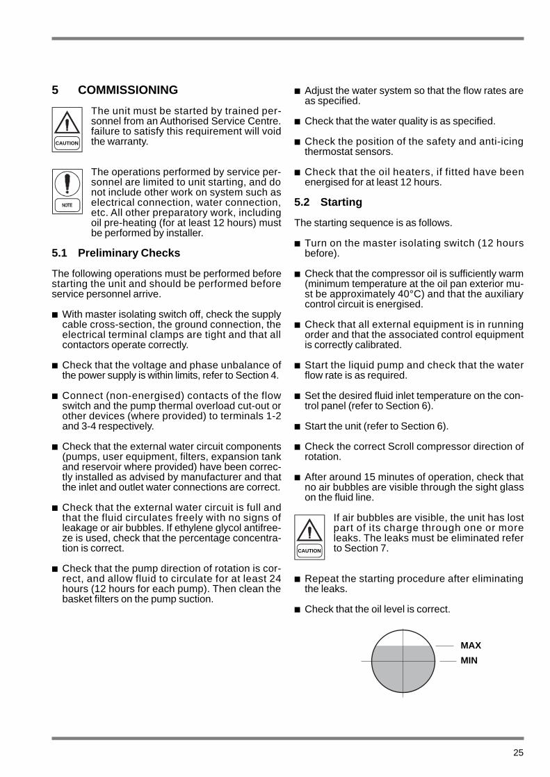
■ Check that the oil level is correct.
CAUTION
CAUTION
MAX
MIN
26
5.3 Performance Check
Check the following:
■ Evaporator manifold inlet water temperature.
■ Evaporator manifold outlet water temperature.
■ Evaporator manifold outlet water flow rate.
■ Compressor current at startup and stable opera-ting conditions.
■ Fan current at startup and stable operating condi-tions.
Check that the saturated evaporation and conden-sation temperatures during operation at high andlow pressure by connecting gauges to the schradervalves on the high and low pressure refrigerant cir-cuits.
5.4 Customer Handover
■ Familiarise the user with the machine operatinginstructions in Section 6.
High pressure side Approximately 15 to18°C above coil inlet airtemperature
Low pressure side Approximately 5 to 7°Cbelow chilled water ou-tlet temperature
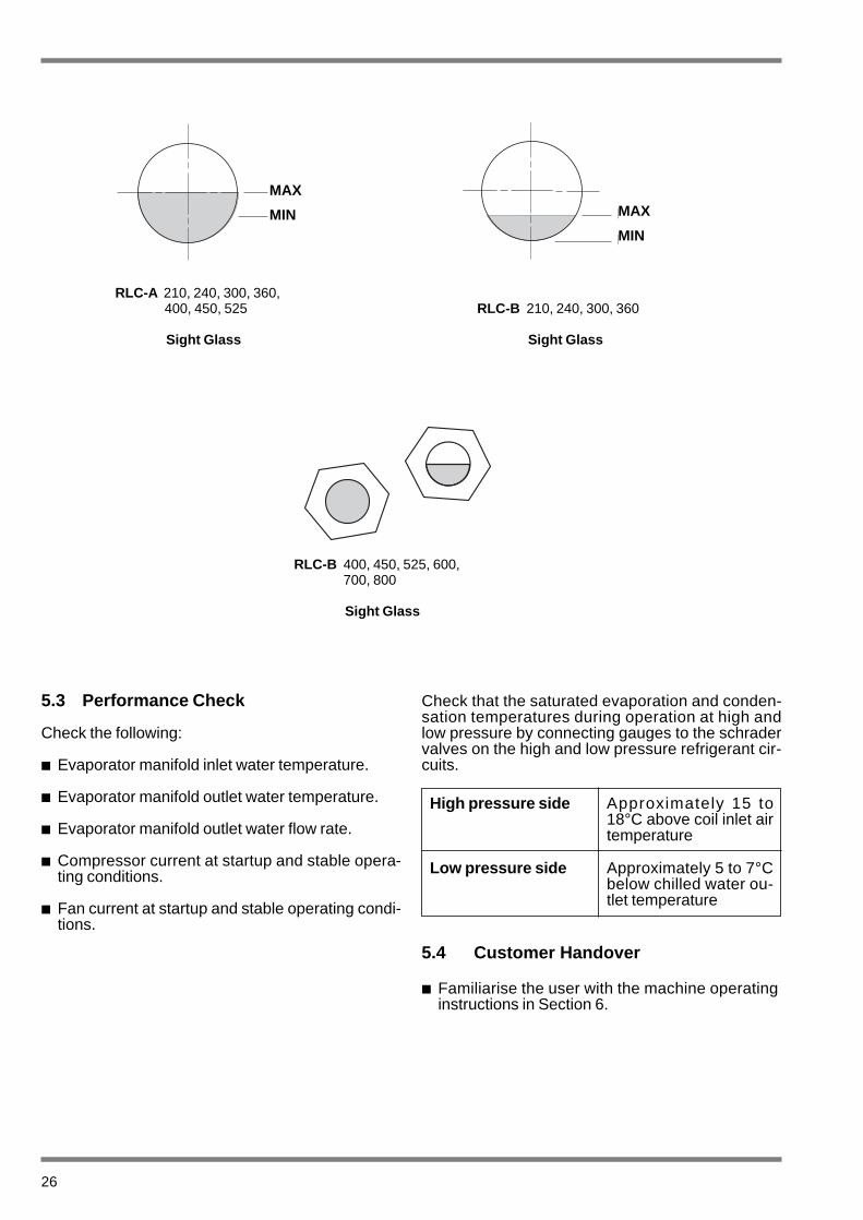
RLC-A 210, 240, 300, 360,400, 450, 525
Sight Glass
RLC-B 210, 240, 300, 360
Sight Glass
RLC-B 400, 450, 525, 600,700, 800
Sight Glass
MAX
MIN
MAX
MIN MAX
MIN
6 OPERATION
RLC series chillers are equipped with a micropro-cessor control logic and regulation managementsystem.The system consists of a unit logic board and a li-quid crystal control panel which manages the con-trol, starting, shutdown and display functions.
6.1 Regulation and control logic
Control logic automatically manages the followingfunctions:
Unit alarm management and display
■ High pressure alarm.
When the alarmis activated, control logic locksout the associated refrigerating circuit and opensthe compressor control chain (fail-safe mode).Alarmis reset from the pressure switch and ma-nually from panel.
■ Low pressure alarm.
When the alarmis activated, control logic locksout the associated refrigerating circuit. Alarmoperation is delayed approximately 30 secondsafter starting (Note 1). Alarm is reset manuallyfrom panel.
■ Differential oil pressure alarm.
When the alarmis activated, control logic locksout the associated refrigerating circuit. Alarmoperation is delayed approximately 120 seconds(Note1). Alarmis reset manually from panel.
■ Compressor thermal overload cut-out alarm.
When the alarmis activated, control logic locksout the associated refrigerating circuit and opensthe compressor control chain. Alarm is reset ma-nually from panel.
■ Anti-freezing alarm.
This alarm is activated when water temperatureat evaporator outlet drops below 3 °C (Note 1).Alarm is reset manually from panel.
■ External interlock alarm.
When the alarmis activated, control logic locksout the unit. Reset is automatic.
■ Fan thermal overload cut-out alarm.
Activation of this alarm locks out the associatedcircuit and fans. Alarmis triggered by fan motors.Reset is automatic.
6.2 Compressor starting logic
Control logic automatically manages all functionsconnected with compressor starting.
■ Anti-cycling timer delay.
Prevents compressor starting attempts frombeing made in quick succession (360 seconds/6minutes) (Note 1).
■ Starting delay.
Prevents compressors from starting simulta-neously (10 seconds) (Note 1).
Part wind starting is used to reduce starting cur-rent. Panel logic automatically manages this star-ting mode, in which only a part of the compressorwinding is activated during starting.
■ Automatic compressor starting sequence change.
Used to ensure that compressors operate for thesame number of hours.
Note 1 These parameters are variable.Changes must be carried out by Itelco-Cli-ma authorised personnel only.
27
The water temperature can be controlled from theinlet or the outlet.
6.3 Water Temperature Regulation (IN)
Regulation is performed via inlet water temperatureSET POINT as shown below. The band is dividedinto a number of steps.
The control regulates the output of the compressoras a function of the system; control is in two steps,four steps or optionally six or eight. Depending onthe required set point and the proportional band(pre selected to be 5°C), the controller determinesthe number of functioning compressors and possi-ble unloading.
The above always refers to nominal water flow witha dT equal to 5°C.
Key1 SET POINT Programmed set point2 Width of regulation band
(set to 5°C)Tr Water return temperature
G1 - G8 Steps of unloading
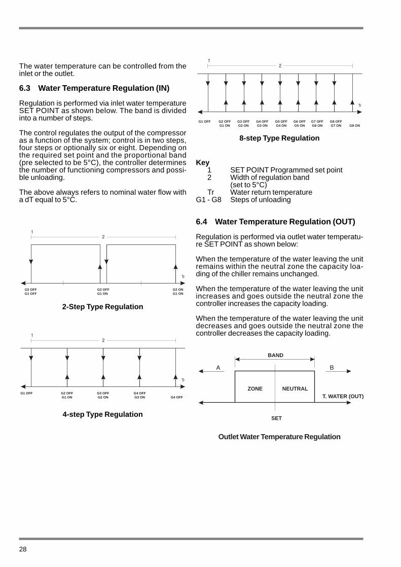
6.4 Water Temperature Regulation (OUT)
Regulation is performed via outlet water temperatu-re SET POINT as shown below:
When the temperature of the water leaving the unitremains within the neutral zone the capacity loa-ding of the chiller remains unchanged.
When the temperature of the water leaving the unitincreases and goes outside the neutral zone thecontroller increases the capacity loading.
When the temperature of the water leaving the unitdecreases and goes outside the neutral zone thecontroller decreases the capacity loading.
28
2-Step Type Regulation
4-step Type Regulation
8-step Type Regulation
TR
IMPOSTAZIONE SET
Outlet Water Temperature Regulation
G2 OFFG1 OFF
G2 OFFG1 ON
G2 ONG1 ON
G1 OFF G2 OFFG1 ON
G3 OFFG2 ON
G4 OFFG3 ON G4 OFF
G1 OFF G2 OFFG1 ON
G3 OFFG2 ON
G4 OFFG3 ON
G5 OFFG4 ON
G6 OFFG5 ON
G7 OFFG6 ON
G8 OFFG7 ON G8 ON
BAND
ZONE NEUTRALT. WATER (OUT)
SET

29
RLC-A, RLC-B Control Panel

30
RLC-A R/P/D Control Panel (Heat Recovery)

31
6.5 Control panel
Key Function
Display Displays operating and faultparameters.
SET POINT + key. (increase temperature SET POINT).
SET POINT - key.(rreduces temperatureSET POINT).
SET POINT display key.
Page key.Calls data display pages.
Circuit 1 or 2 power key and LED.(Select circuit 1 or 2).
100% power level indicatingLED for circuit 1 and 2compressors.
Compressor partialisation indicating LED for circuit 1 and 2 compressors
Circuit 1 or 2 high pressure alarmLED. Indicates that high pressureswitch for circuit 1 or 2 has beenactivated.
Circuit 1 or 2 low pressure alarmLED. Indicates that low pressureswitch for circuit 1 or 2 has beenactivated.
Circuit 1 or 2 differential oilpressure alarm LED (semi-hermetic compressor only).Indicates that differential oil pressure switch for circuit 1 or 2has been activated.
Circuit 1 or 2 compressor thermaloverload alarm LED. Indicatestht compressor thermal overload has been activatedfor circuit 1 or 2.
Key Funtion
Voltage indicator LED. Indicates that unit is connectedto power supply.
Anti-freezing alarm LED.Indicates that water temperatureat evaporator outlet is belowsafe limit.
External interlock alarm LED.
Fan thermal overload alarm LEDIndicates that a fan thermal overload cut-out has been activated.
Warm weather mode start keyand LED. Starts the unit in the cooling mode.Led lights up to indicateoperating in cooling mode.
Heat Recovery start key and LED. Starts the unit heat recoverymode. Led lights up to indicateoperating in recovery mode.
Service mode key and LED.(For use only by authorised service personnel).

32
6.6 Unit Starting
Proceed as follows to start the unit:
■ Turn the master isolating switch to the ON posi-tion to energise unit.
Check that LED (voltage indicator) goes on.
The following display will appear on screen:
Wait (circa 10 sec.) for this message to disappearand check that there are no active alarm signals.
■ Prepare the two circuits for operation by pressing
the key for each circuit.
unit is now in stand-by and LED’s for the asso-ciated circuits are on.
■ Press key to start the unit in the cooling mode.
LED will go on.
Compressor operation and power level will be indi-
cated by LED’s for each circuit.
■ Check that SET POINT is as desired (SETPOINT established at the factory is 8°C).
If necessary, change the set point as described in6.7.
Data and Temperature Display
■ Display 1 (Models RLC 150 to RLC 800)
Evaporator inlet water temperature
Evaporator outlet water temperature
■ Display 2
Air temperature
In Tmp WatOut Tmp Wat
Condenser CoilsAir Tmp

33
■ Display 3
Operating hours for compressors 1 and 2.
Press key to scroll displays.
Alarm readouts are shown at the foot of display 3.
Press page key again to return to display 1.
6.7 Set point
To display cooling mode SET POINT:
■ Press key with unit operating in cooling mode.
To change SET POINT, Proceed as follows:
■ Display SET POINT as directed above;
■ Press page key to move onto the digit to bechanged.
■ Change digit using and keys;
■ Press key to confirm;
■ To change SET POINT with compressors off, de-
activate the two circuits by pressing keys.
6.8 Heat Recovery Operation
The heat recovery option is activated by the heatrecovery start key on the control panel, which is illu-minated when activated. Heat recovery operation iscontrolled by a factory wired thermostat, mountedby the installer, in the warm water flow from the heatrecovery condenser(s).
The heat recovery function is by means of a four-way valve in the discharge line from the compres-sor to the condenser. The four-way valve diverts hotrefrigerant gas to the recovery condenser, when thethermostat is calling for heat.
When the leaving warm water temperature reachesthe set point of the thermostat the four-way valve di-verts the refrigerant to the air cooled condenser andthe heat is dissipated to the ambient air. As thewarm water temperature leaving the recovery ves-sel falls below the set point of the thermostat thefour-way valve diverts the refrigerant back to theheat recovery condenser.
6.9 Alarm Display and Reset
Alarms are indicated by the associated panel LED’sand by messages on the liquid crystal display. Theletters “AL” will appear in the upper right corner ofdisplay to indicate that an alarm is active or hasbeen stored in memory. To display alarm, press
page key several times until the alarm displayappears.
To reset and delete memorised alarms, press page
key until the following display appears:
Then press key to delete and reset alarms
6.10 Unit Shutdown
■ Press warm weather mode key to stop theunit.
■ Turn master isolating switch to OFF position tode-energise the unit.
6.11 Electromechanical Safety Devices
Each refrigerating circuit on the RLC Series units isprotected by anti-freezing devices implemented bythe “Chiller Control” panel and a set of electrome-chanical safety devices including a high pressureswitch, a low pressure switch and a differential oilpressure switch (units with semi-hermetic compres-sor only).
Hour Counter

Ant-freezing device (supplied with unit)
Units are provided with anti-freezing device consi-sting of an electric heating element in contact withthe refrigerant/water heat exchanger. Heating ele-ment is activated whenever water temperature dro-ps below 2°C, even when the unit is off. An anti-freeze alarm stops the unit if outlet water tempera-ture drops below 3°C. During the cold season, it isadvisable to drain water circuit to prevent ice dama-ge to lines. If this is not possible, do not cut offpower supply to the unit to ensure that the anti-free-ze heating element will be activated if needed.
High pressure switch
Manual-reset switch opens contacts.
Circuit can be reset manually through “Chiller Con-trol” panel, after resetting device.
Low pressure switch
Automatic-reset switch opens contacts.Circuit can be reset manually through “Chiller Con-trol” panel.
Differential oil pressure switch
This instrument is provided on circuits with semi-hermetic compressor. Switch senses pressure dif-ferential across compressor casing and compres-sor oil delivery.
Switch cut-in is delayed 120 seconds to allow pres-sure to rise after compressor start-up. Circuit canbe reset manually through control panel.
34
Alarm Displays
Compressor 1 or 2Thermal OverloadCut-out
Circuit 1 or 2 FanThermal OverloadCut-out
Circuit 1 or 2 HIGHPressure Switch
* Circuit 1 or 2HIGH PressureLimit Exceeded
Evap. Outlet 1Water Low Temp.Limit Exceeded
* Circuit 1 or 2 LowPressure LimitExceeded
Evap. Outlet 2Water Temp. LimitExceeded
Evap. Inlet WaterHigh temperatureLimit Exceeded
Evap. Inlet WaterLow TemperatureLimit Exceeded
circuit 1 or 2 LOWPressure Switch
Compressor 1 or 2Maintenance
Circuit 1 or 2Differential OilPressure Switch
Analogue Input forRemote SetpointOut of Range
Temperature SetPoint Out of Range External Interlock Mistake in Interface
Managing
EPROMDamaged
Timer Missing orNot Working
* Only if optional pressure and temperaturesensors are fitted

7 MAINTENANCE
Never release refrigerant to the atmo-sphere when emptying the refrigeratingcircuit. Suitable retrieval equipmentmust be used. If reclaimed refrigerantcannot be re-used. It must be returnedto the manufacturer.
Never discard used compressor oil, asit contains refrigerant in solution. Re-turn used oil to the oil manufacturer.The Safety Section of this manualshould be read carefully before attemp-ting any maintenance operation on theunit.
Unless otherwise indicated, the maintenance ope-rations described below can be performed by anyproperly trained maintenance technician.
7.1 General Requirements
The RLC range has been designed to work conti-nuously provided they are regularly maintained andoperated within the limitations given in this manual.each unit should be maintained in accordance withthe schedule by the operator/customer, backed upby regular service and maintenance visits by anauthorised Service Centre.
It is the responsibility of the owner to provide forthese regular maintenance requirements and/or en-ter into a maintenance agreement with a ServiceCentre to protect the operation of the unit.
If damage or a system failure occurs due to impro-per maintenance during the warranty period, manu-facturer shall not be liable for costs incurred to re-turn the unit to satisfactory condition.
This maintenance section applies only to the basicRLC unit and may, on individual contracts, be sup-plemented by additional requirements to cover anymodifications or ancillary equipment as applicable.
7.2 Daily Maintenance
The maintenance checks should be carried out inaccordance with the maintenance schedule detailedbelow by a competent person. Please note, howe-ver, that RLC series units are not generally user ser-viceable and no attempt should be made to rectifyfaults or problems found during daily checks. If inany doubt, contact an Authorised Service Centre.
Scheduled Maintenance
35
Check evaporator leavingliquit temperature
Check heat evaporatorpressure drop
Check electrical powerconsumption
Check suction pressureand temperature
Check discharge pressureand temperature
Check compressoroil level
Check for gas bubblesin refrigerant
Check finned coil cleanliness
Check oil heater efficiency
Check Remote Control Unit
Check low pressureswitch
Check high pressureswitch
Check diff. oil pressureswitch
Check heat exchangerinsulation
Check clamp tightness
Check terminal screwtightness
Clean outside surfacewith soapy water
Straighten coil fins
Check density of anycirculating brine
Drain evaporator of addantifreeze
Operation
Dai
ly
Wee
kly
Mon
thly
Sta
rt of
Sea
son
End
of S
easo
n
•••••••
•••
••••••••••
WARNING
WARNING
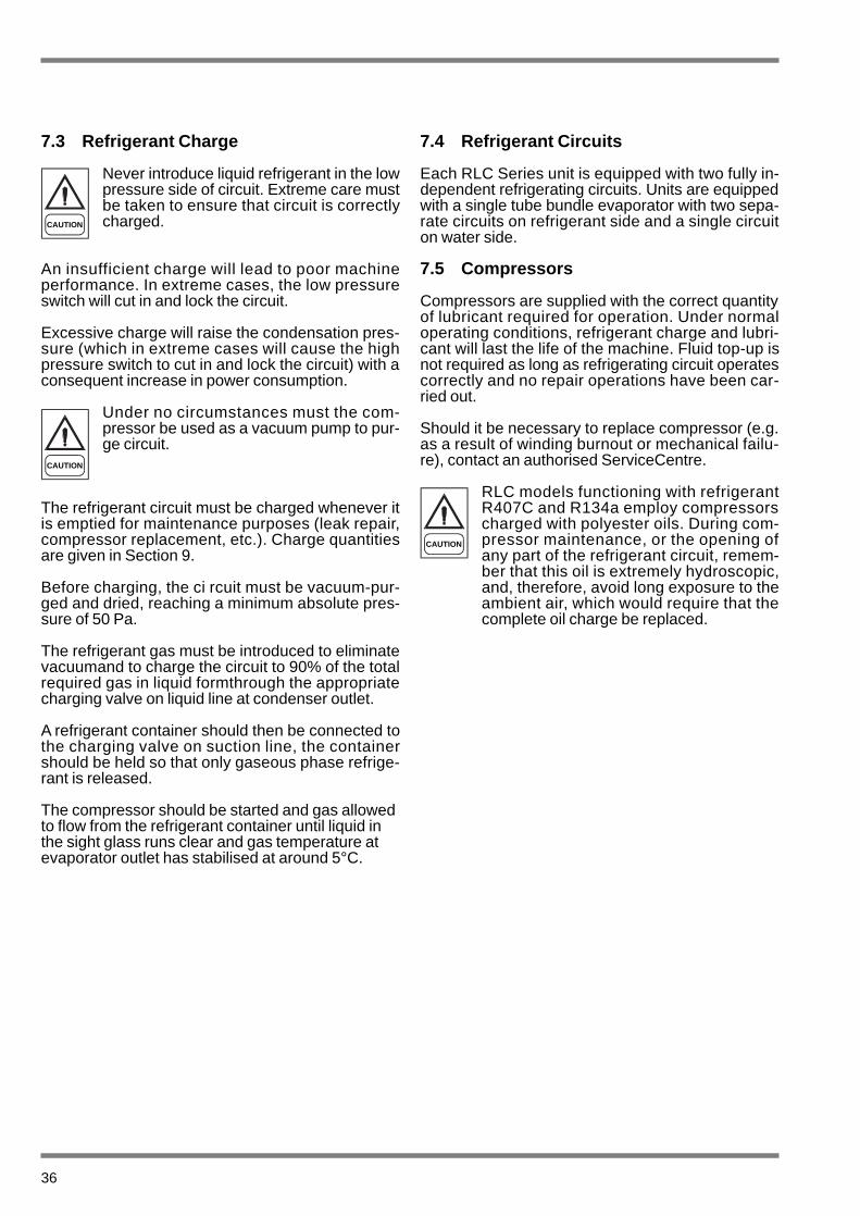
7.3 Refrigerant Charge
Never introduce liquid refrigerant in the lowpressure side of circuit. Extreme care mustbe taken to ensure that circuit is correctlycharged.
An insufficient charge will lead to poor machineperformance. In extreme cases, the low pressureswitch will cut in and lock the circuit.
Excessive charge will raise the condensation pres-sure (which in extreme cases will cause the highpressure switch to cut in and lock the circuit) with aconsequent increase in power consumption.
Under no circumstances must the com-pressor be used as a vacuum pump to pur-ge circuit.
The refrigerant circuit must be charged whenever itis emptied for maintenance purposes (leak repair,compressor replacement, etc.). Charge quantitiesare given in Section 9.
Before charging, the ci rcuit must be vacuum-pur-ged and dried, reaching a minimum absolute pres-sure of 50 Pa.
The refrigerant gas must be introduced to eliminatevacuumand to charge the circuit to 90% of the totalrequired gas in liquid formthrough the appropriatecharging valve on liquid line at condenser outlet.
A refrigerant container should then be connected tothe charging valve on suction line, the containershould be held so that only gaseous phase refrige-rant is released.
The compressor should be started and gas allowedto flow from the refrigerant container until liquid inthe sight glass runs clear and gas temperature atevaporator outlet has stabilised at around 5°C.
7.4 Refrigerant Circuits
Each RLC Series unit is equipped with two fully in-dependent refrigerating circuits. Units are equippedwith a single tube bundle evaporator with two sepa-rate circuits on refrigerant side and a single circuiton water side.
7.5 Compressors
Compressors are supplied with the correct quantityof lubricant required for operation. Under normaloperating conditions, refrigerant charge and lubri-cant will last the life of the machine. Fluid top-up isnot required as long as refrigerating circuit operatescorrectly and no repair operations have been car-ried out.
Should it be necessary to replace compressor (e.g.as a result of winding burnout or mechanical failu-re), contact an authorised ServiceCentre.
RLC models functioning with refrigerantR407C and R134a employ compressorscharged with polyester oils. During com-pressor maintenance, or the opening ofany part of the refrigerant circuit, remem-ber that this oil is extremely hydroscopic,and, therefore, avoid long exposure to theambient air, which would require that thecomplete oil charge be replaced.
36
CAUTION
CAUTION
CAUTION

7.6 Condenser Coils
Condenser coils feature copper tubes and alumi-nium fins. Should refrigerant leakage take place asa result of accidental impact or damage. The coilsmust only be repaired or replaced by an AuthorisedService Centres.
To ensure high condenser coil serviceability andheat exchange, the condenser surfaces must bekept free of impurities such as leaves, fibres, in-sects, dirt etc. Soiled condenser coils will increasepower consumption. In addition, the maximumpressure alarm may cut in and lock out the unit.
Take care not to damage aluminium finsduring cleaning.
The condenser should be cleaned using compres-sed air directed parallel to aluminium fins and in theopposite direction to that of normal air circulation. Avacuum cleaner may be used to clean the conden-ser coil from outside. The coil may also be cleanedwith soapy water using a suitable spray nozzle.
7.7 Condenser Fans
Each condenser fan features a wing-profile impellerand cylindrical nozzle. The fan motor bearings arelubricated for life.
Ensure that fans rotate in the direction indicated byarrowbefore starting machine following repair workinvolving 3-phase disconnection (air f low upwards).
If fan rotation is not correct, disconnect and inverttwo of the three phases supplying the motor.
7.8 Filter Drier
Refrigerating circuits are provided with filter/driers.
The filter/driers are inspectable cartridge type onmodels 210/800, and non-inspectable strainer typeon smaller units.
Filter/drier clogging will be indicated by bubbles inthe sight glass, or by a difference in temperatureupstream and downstreamof filter/drier.
If bubbles persist after changing cartridge, the ma-chine has lost part of its refrigerant charge throughone or more leaks which must be identified and re-paired.
7.9 Sight Glass
The sight glass is used to observe refrigerant flowand moisture content. Bubbles in flow indicate thatfilter/drier (where provided) is clogged, or that refri-gerant charge is low.
A colour indicator is located inside the sight glass.Compare the colour of the indicator with the scaleon the sight glass lock ring to determine the moistu-re content of refrigerant. If moisture content is toohigh, proceed as follows:
For machines with hermetic compressors, dischar-ge the circuit without releasing refrigerant to the at-mosphere. Vacuum-purge the circuit and replenishthe charge.
For machines with semi-hermetic compressors,change the filter cartridge, operate the unit for oneday and check the moisture content again.
No further action is required if the moisture contentreturns to normal. If the moisture content is still toohigh, change the filter/drier again, start the unit andoperate for a further day.
37
CAUTION
7.10 Thermostatic Expansion Valve
RLC refrigerating circuits are provided with a ther-mostatic expansion valve with an external equali-ser. Valves are calibrated at the factory for a 5°Ctemperature rise.
To check the temperature rise:
Read the suction pressure on the units gauge panelor on a pressure gauge connected to charging val-ve on suction side.
Using the pressure gauge temperature scale, de-termine the saturated suction temperature Tsa cor-responding to this pressure.
Determine the effective suction temperature Tseusing a contact thermometer applied to the evapo-rator gas outlet fitting.
Temperature rise S is given by:
S = Tse - Tsa
The temperature rise can be corrected using theadjuster screw on the thermostatic expansion val-ve. Turn the adjuster screw through a single revolu-tion and operate the unit for five minutes. Thencheck the temperature rise again and correct as ne-cessary.
If the thermostatic expansion valve does not reactto temperature rise calibration, it is probably mal-functioning and must be replaced. Valve replace-ment must be performed by an authorised ServiceCentre.
7.11 Evaporator
Check the heat exchanger water side for cleanli-ness at regular intervals. This may be accompli-shed by checking water side pressure drop (refer toSection 9) or simply by checking the fluid tempera-tures at heat exchanger inlet and outlet and compa-ring them with evaporation temperatures.
For effective heat exchange, the water outlet tem-perature and the saturated evaporation temperatu-re should differ by 5 to 7°C. A larger difference indi-cates that the heat exchanger is operating ineffi-ciently, and is thus soiled.
If soiled, the heat exchanger must be chemically clea-ned by authorised Itelco-Clima service personnel.
For other types of service (special maintenance,heat exchanger replacement, etc.), contact anauthorised Service Centre.
38
39
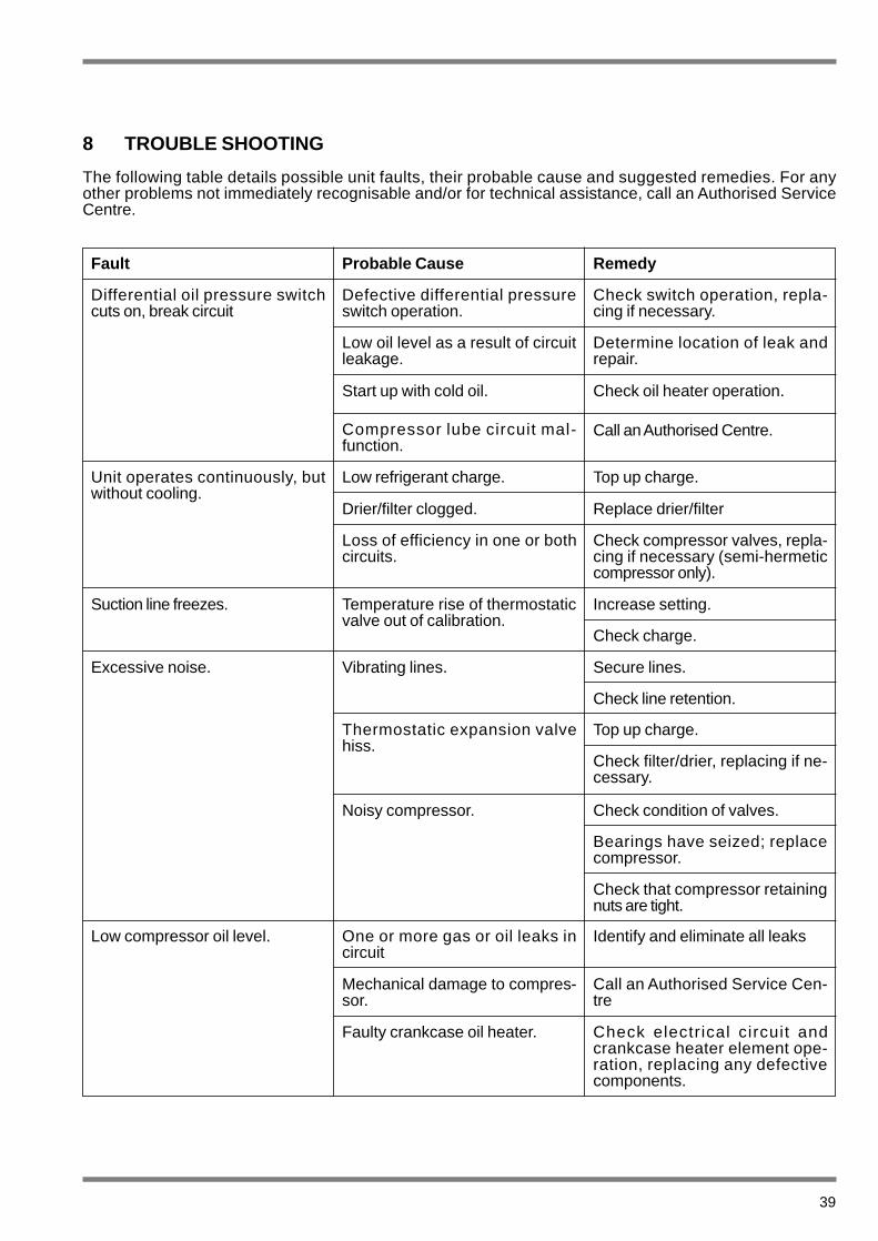
8 TROUBLE SHOOTING
The following table details possible unit faults, their probable cause and suggested remedies. For anyother problems not immediately recognisable and/or for technical assistance, call an Authorised ServiceCentre.
Fault Probable Cause Remedy
Differential oil pressure switchcuts on, break circuit
Unit operates continuously, butwithout cooling.
Suction line freezes.
Excessive noise.
Low compressor oil level. One or more gas or oil leaks incircuit
Mechanical damage to compres-sor.
Faulty crankcase oil heater. Check electrical circuit andcrankcase heater element ope-ration, replacing any defectivecomponents.
Call an Authorised Service Cen-tre
Identify and eliminate all leaks
Defective differential pressureswitch operation.
Low oil level as a result of circuitleakage.
Start up with cold oil.
Compressor lube circuit mal-function.
Low refrigerant charge.
Drier/filter clogged.
Loss of efficiency in one or bothcircuits.
Temperature rise of thermostaticvalve out of calibration.
Vibrating lines.
Thermostatic expansion valvehiss.
Noisy compressor. Check condition of valves.
Bearings have seized; replacecompressor.
Check that compressor retainingnuts are tight.
Top up charge.
Check filter/drier, replacing if ne-cessary.
Check switch operation, repla-cing if necessary.
Determine location of leak andrepair.
Check oil heater operation.
Call an Authorised Centre.
Top up charge.
Replace drier/filter
Check compressor valves, repla-cing if necessary (semi-hermeticcompressor only).
Increase setting.
Check charge.
Secure lines.
Check line retention.

40
Fault Probable Cause Remedy
One or both compressors notworking.
Low pressure switch cuts in,braking circuit.
High pressure switch cuts in,braking circuit.
Liquid line too hot.
Liquit line freezes Liquid line valve partially closed.
Receiver/drier clogged. Replace cartridge.
Check that all valves are open.
Insufficient charge. Identify and eliminate causes ofcharge loss and top up charge.
High pressure switch malfunc-tion.
Delivery valve partially closed.
Non-condensables in circuit.
Condenser fan(s) inoperative. Check wiring and motors. Repairor replace if necessary.
Purge circuit.
Open valve, replacing if neces-sary.
Check switch operation, repla-cing if necessary.
Gas leakage.
Insufficient charge.
Pressure switch failure. Replace pressure switch.
Top up charge.
Identify and eliminate leakage.
Power circuit interrupted.
High pressure switch activation.
Control circuit fuse blown
Loose terminal clamps.
Power circuit thermal overloadcut-out activation.
Incorrect wiring.
Line voltage too low.
Compressor motor short-circui-ted.
Compressor seizure Replace compressor.
Check motor winding continuity.
Check line voltage. If problemdue to system, eliminate it.If problem is due to distributionnetwork, inform the electricitysupply company.
Check control and safety devicewiring.
Check operation of control andsafety devices.Identify and eliminate cause ofactivation.
Check clamp tightness.
Check control circuit for earthleakage and shorts.Change fuses.
Reset pressure switch from pa-nel and re-start machine.Identify and eliminate causes ofpressure switch activation.
Check power circuit for earthleakage and shorts.Check fuses.

41
9 TECHNICAL DATA
9.1 Pressure Drop Graphs
RLC-A & RLC-B All Models - Evaporator
FLOW RATE (l/s)
PR
ES
SU
RE
DR
OP
(kP
a)

42
RLC-A R/P Models – Heat Recovery Condenser
Note: R Models - Pressure drop is for each Condenser
FLOW RATE (l/s)
PR
ES
SU
RE
DR
OP
(kP
a)
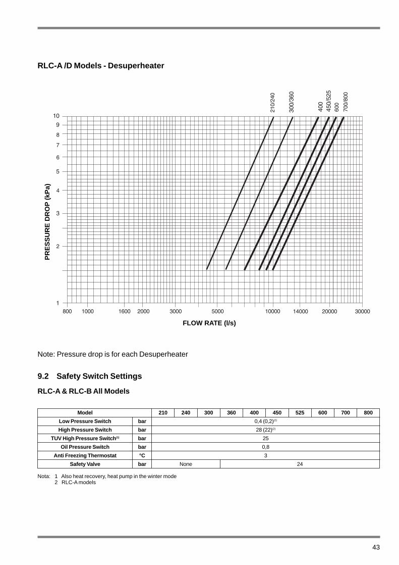
Model 210 240 300 360 400 450 525 600 700 800
Low Pressure Switch bar 0,4 (0,2)(2)
High Pressure Switch bar 28 (22)(2)
TUV High Pressure Switch (1) bar 25
Oil Pressure Switch bar 0,8
Anti Freezing Thermostat °C 3
Safety Valve bar None 24
43
RLC-A /D Models - Desuperheater
Note: Pressure drop is for each Desuperheater
9.2 Safety Switch Settings
RLC-A & RLC-B All Models
Nota: 1 Also heat recovery, heat pump in the winter mode2 RLC-A models
PR
ES
SU
RE
DR
OP
(kP
a)
FLOW RATE (l/s)
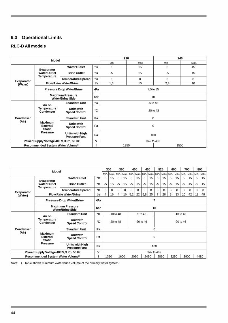
Model210 240
Min. Max. Min. Max.
Water Outlet °C 6 15 6 15
°C -5 15 -5 15
Temperature Spread °C 3 8 3 8Flow Rater Water/Brine l/s 1,5 10 2,3 10
kPa 7,5 to 85
bar 10
Standard Unit °C -5 to 48
°C -20 to 48
Standard Unit Pa 0
Pa 0
Pa 100
Power Supply Voltage 400 V, 3 Ph, 50 Hz V 342 to 462Recommended System Water Volume (1) l 1250 1500
9.3 Operational Limits
RLC-B All models
Evaporator(Water)
EvaporatorWater OutletTemperature
Brine Outlet
Pressure Drop Water/Brine
Condenser(Air)
Maximum PressureWater/Brine Side
Air on TemperatureCondenser
Units with Speed Control
MaximumExternal
StaticPressure
Units withSpeed Control
Units with HighPressure Fans
Model300 360 400 450 525 600 700 800
Min. Max. Min. Max. Min. Max. Min. Max. Min. Max. Min. Max. Min. Max. Min. Max.
Water Outlet °C 6 15 6 15 5 15 5 15 5 15 5 15 5 15 5 15
°C -5 15 -5 15 -5 15 -5 15 -5 15 -5 15 -5 15 -5 15
Temperature Spread °C 3 8 3 8 3 8 3 8 3 8 3 8 3 8 3 8Flow Rate Water/Brine l/s 4 16 4 16 5,2 22 5,8 25 7 28 8 33 10 42 11 48
kPa 7
bar 10
Standard Unit °C -10 to 48 -5 to 46 -10 to 46
°C -20 to 48 -20 to 46 -20 to 46
Standard Unit Pa 0
Pa 0
Pa 100
Power Supply Voltage 400 V, 3 Ph, 50 Hz V 342 to 462Recommended System Water Volume (1) l 1350 1600 2050 2450 2850 3250 3900 4480
Evaporator(Water)
EvaporatorWater OutletTemperature
Brine Outlet
Pressure Drop Water/Brine
Condenser(Air)
Maximum PressureWater/Brine Side
Air onTemperatureCondenser
Unit withSpeed Control
MaximumExternal
StaticPressure
Unit withSpeed Control
Units with HighPressure Fans
Note: 1 Table shows minimum water/brine volume of the primary water system
44

45
Model210 240
Min. Max. Min. Max.
Water Outlet °C 5 15 5 15
°C -10 15 -10 15
Temperature Spread °C 3 8 3 8Flow Rate Water/Brine l/s 2,3 10 2,3 10
kPa 7,5 to 85
bar 10
Standard Unit °C -5 to 48
°C -20 to 48
Standard Unit Pa 0
Pa 0
Pa 100
Water Outlet °C 35 to 50Temperature Spread °C 3 to 10
Water Outlet °C 40 to 70
Power Supply Voltage 400 V, 3 Ph, 50 Hz V 342 to 462Recommended System Water Volume (1) l 1250 1500
RLC-A All Models
Evaporator(Water)
EvaporatorWater OutletTemperature
Brine Outlet
Pressure Drop Water/Brine
Condenser(Air)
Maximum PressureWater/Brine Side
Air onTemperatureCondenser
Units with Speed Control
MaximumExternal
StaticPressure
Units withSpeed Control
Units with HighPressure Fans
Condenser HRC RLC-A/R/P
RLC-A/DDesuperheater
Model300 360 400 450 525
Min. Max. Min. Max. Min. Max. Min. Max. Min. Max.
Water Outlet °C 5 15 5 15 5 15 5 15 5 15
°C -10 15 -10 15 -10 15 -10 15 -10 15
Temperature Spread °C 3 8 3 8 3 8 3 8 3 8Flow Rate Water/Brine l/s 4 16 4 16 4 16 4 16 4 16
kPa 7,5 to 85
bar 10
Standard Unit °C -10 to 48
°C -20 to 48
Standard Unit Pa 0
Pa 0
Pa 100
Water Outlet °C 35 to 50Temperature Spread °C 3 to 10
Water Outlet °C 40 to 70
Power Supply Voltage 400 V, 3 Ph, 50 Hz V 342 to 462Recommended System Water Volume (1) l 1350 1600 2050 2450 2850
Evaporator(Water)
EvaporatorWater OutletTemperature
Brine Outlet
Pressure Drip Water/Brine
Condenser(Air)
Maximum PressureWater/Brine Side
Air onTemperatureCondenser
Units withSpeed Control
MaximumExternal
StaticPressure
Units withSpeed Control
Units with HighPressure Fans
Condenser HRC RLC-A/R/P
RLC-A/DDesuperheater
Note: 1 Table shows minimum water/brine volume of the primary water system

46
Model 210 240Type semi-hermetic
m3/h 107 127
Type semi-hermetic
m3/h 107 127
Quantity 2 2Number of Cylinders 6 6
Revs. per Minute rpm 1450 1450
dm3 7,4 7,7
100/50 100/50Quantity 1 1
Type (Direct Expansion) Shell and TubeNumber of Refrigerant Circuits 2 2
l 33 33
Refrigerant Volume dm 3 16,7 16,7Face Area m 2 8,3 8,3
Number of Rows 2 3
Fan Diameter mm 710 710Number 6 6
Power Input at 890 rpm kW 0,9 0,9Air Flow Rate m 3/s 24 22
Refrigerant Charge R 407C kg 2 x 15 2 x 21Operational Weight Aluminium Fins kg 1780 1890
Shipping Weight kg 1740 1850Copper/Copper Coils kg 344 344
RLC/R kg 190 200RLC/P kg 95 100RLC/D kg 40 50
Length mm 4040 4040Width mm 2040 2040Height mm 1730 1730
Compressor
Circuit 1
Circuit 2
TheoreticalDisplacement
TheoreticalDisplacement
Evaporator
Air CooledCondenser
Fans
AdditionalWeight
Water Volume perEvaporator
Number of Loading Stages
Dimensions
Note: 1 Per condenser
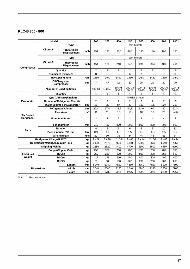
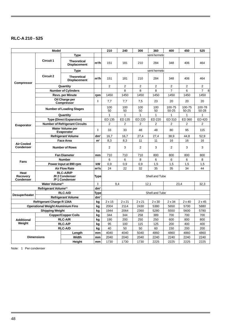
9.4 Physical Data
RLC-B 210 - 240
Oil Charge perCompressor
47
Model 300 360 400 450 525 600 700 800Type semi-hermetic
m3/h 151 180 202 180 180 180 180 180
Type semi-hermetic
m3/h 151 180 210 243 284 324 406 464
Quantity 2 2 2 2 2 2 2 2Number of Cylinders 8 8 8 6 7 8 7 8
Revs. per Minute rpm 1450 1450 1450 1450 1450 1450 1450 1450
dm3 7,7 7,7 7,5 20 20 20 20 20
100-50 100-50 100-75 100-75 100-75 100-75 100-75 100-7550-25 50-25 50-25 50-25 50-25 50-25
Quantity 1 1 1 1 1 1 1 1Type (Direct Expansion) Shell and Tube
Number of Refrigerant Circuits 2 2 2 2 2 2 2 2Water Volume per Evaporator dm 3 55 55 87 80 133 125 222 206
Refrigerant Volume dm 3 27,4 27,4 38,9 44,8 52,9 60 80 92,3Face Area m 2 11 11 16 16 16 16 20 24,6
Number of Rows 2 3 2 3 3 4 4 4
Fan Diameter mm 710 710 800 800 800 800 800 800Number 8 8 6 6 8 8 10 12
Power Input at 890 rpm kW 0,9 0,9 1,5 1,5 1,5 1,5 1,5 1,5Air Flow Rate m 3/s 32 30 35 34 44 43 53 64
Refrigerant Charge R 407C kg 2 x 21 2 x 30 2 x 33 2 x 40 2 x 44 2 x 50 2 x 63 2 x 74Operational Weight Aluminium Fins kg 2430 2570 4500 4800 5200 5600 6640 7050
Shipping Weight kg 2380 2520 4400 4700 5100 5500 6450 6900Copper/Copper Coils kg 258 389 700 700 700 736 700 700
RLC/R kg 250 250 600 800 800 800 660 660RLC/P kg 115 125 200 400 400 400 400 400RLC/D kg 50 60 150 200 200 200 200 200
Length mm 5040 5040 4860 4860 4860 4860 6100 7100Width mm 2040 2040 2240 2240 2240 2240 2260 2260Height mm 1730 1730 2225 2225 2225 2225 2250 2250
Compressor
Circuit 1
Circuit 2
Theoretical Displacement
Theoretical Displacement
Evaporator
Air CooledCondenser
Fans
AdditionalWeight
Oil Charge perCompressor
Number of Loading Steps
Dimensions
Note: 1 Per condenser
RLC-B 300 - 800
48
Model 210 240 300 360 400 450 525Type semi hermetic
m3/h 151 181 210 284 348 406 464
Type semi hermetic
m3/h 151 181 210 284 348 406 464
Quantity 2 2 2 2 2 2 2Number of Cylinders 8 8 8 7 6 7 8
Revs. per Minute rpm 1450 1450 1450 1450 1450 1450 1450
l 7,7 7,7 7,5 23 20 20 20
100 100 100 100 100-75 100-75 100-7850 50 50 50 50-25 50-25 50-28
Quantity 1 1 1 1 1 1 1Type (Direct Expansion) ED 135 ED 135 ED 220 ED 220 ED 310 ED 360 ED 420
Number of Refrigerant Circuits 2 2 2 2 2 2 2
l 33 33 48 48 80 95 115
Refrigerant Volume dm 3 16,7 16,7 27,4 27,4 38,9 44,8 52,9Face Area m 2 8,3 8,3 11 11 16 16 16
Number of Rows 2 3 2 3 2 3 3
Fan Diameter mm 710 710 710 800 800 800 800Number 6 6 8 6 6 6 8
Power Input at 890 rpm kW 0,9 0,9 0,9 1,5 1,5 1,5 1,5Air Flow Rate m 3/s 24 22 32 35 35 34 44
Type Shell and Tube
Water Volume (1) l 9,4 12,1 23,4 32,3Refrigerant Volume (1) dm3
RLC-A/D Type Shell and TubeRefrigerant Volume dm 3
Refrigerant Charge R 134A kg 2 x 15 2 x 21 2 x 21 2 x 30 2 x 34 2 x 40 2 x 45Operational Weight Aluminium Fins kg 2004 2114 2430 5380 5650 5700 5880
Shipping Weight kg 1944 2064 2360 5280 5550 5600 5780Copper/Copper Coils kg 344 344 258 389 700 700 700
RLC-A/R kg 190 200 250 250 600 800 800RLC-A/P kg 95 100 115 125 200 400 400RLC-A/D kg 40 50 50 60 150 200 200
Length mm 4040 4040 5040 4860 4860 4860 4860Width mm 2040 2040 2040 2240 2240 2240 2240Height mm 1730 1730 1730 2225 2225 2225 2225
Compressor
Circuit 1
Circuit 2
TheoreticalDisplacement
TheoreticalDisplacement
Evaporator
Air CooledCondenser
Fans
HeatRecovery
Condenser
AdditionalWeight
Desuperheater
Oil Charge perCompressor
Number of Loading Stages
RLC-A/R/P/R 2 Condenser/P 1 Condenser
Dimensions
Note: 1 Per condenser
RLC-A 210 - 525
Water Volume perEvaporator
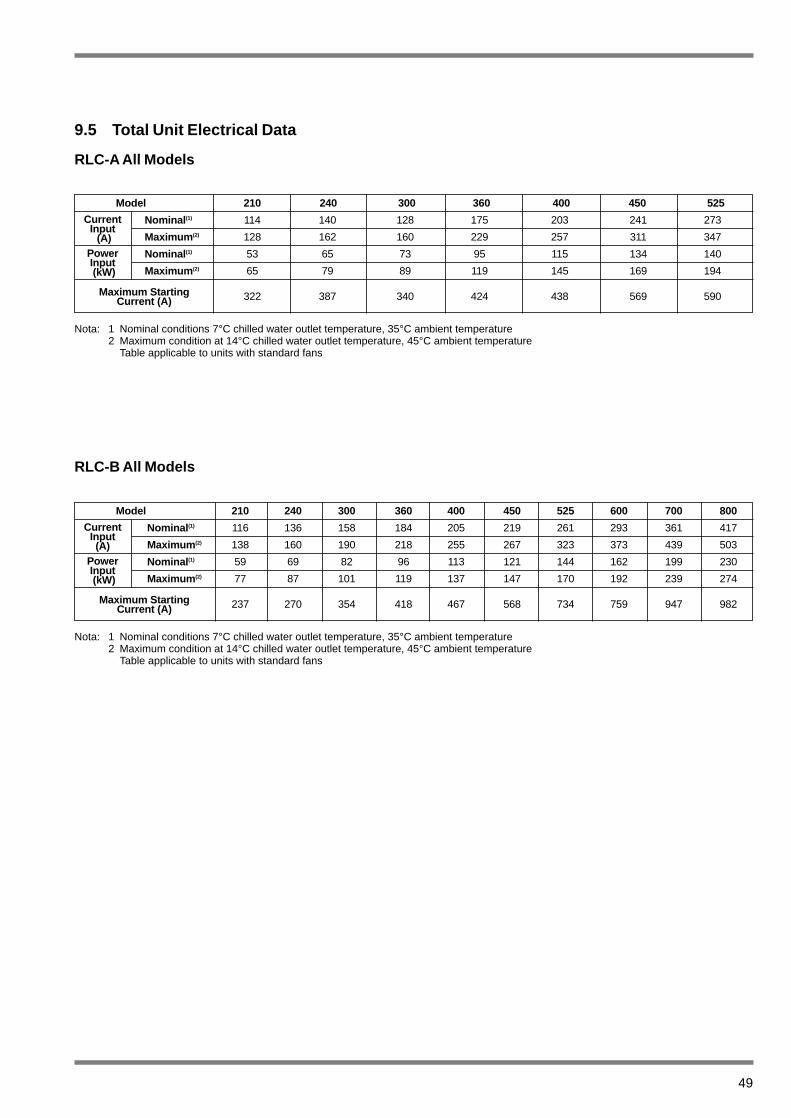
49
9.5 Total Unit Electrical Data
RLC-A All Models
RLC-B All Models
Model 210 240 300 360 400 450 525 600 700 800
Nominal (1) 116 136 158 184 205 219 261 293 361 417
Maximum (2) 138 160 190 218 255 267 323 373 439 503
Nominal (1) 59 69 82 96 113 121 144 162 199 230
Maximum (2) 77 87 101 119 137 147 170 192 239 274
237 270 354 418 467 568 734 759 947 982
Nota: 1 Nominal conditions 7°C chilled water outlet temperature, 35°C ambient temperature2 Maximum condition at 14°C chilled water outlet temperature, 45°C ambient temperature
Table applicable to units with standard fans
CurrentInput(A)
PowerInput(kW)
Maximum StartingCurrent (A)
Model 210 240 300 360 400 450 525
Nominal (1) 114 140 128 175 203 241 273
Maximum (2) 128 162 160 229 257 311 347
Nominal (1) 53 65 73 95 115 134 140
Maximum (2) 65 79 89 119 145 169 194
322 387 340 424 438 569 590
Nota: 1 Nominal conditions 7°C chilled water outlet temperature, 35°C ambient temperature2 Maximum condition at 14°C chilled water outlet temperature, 45°C ambient temperature
Table applicable to units with standard fans
CurrentInput
(A)PowerInput(kW)
Maximum StartingCurrent (A)
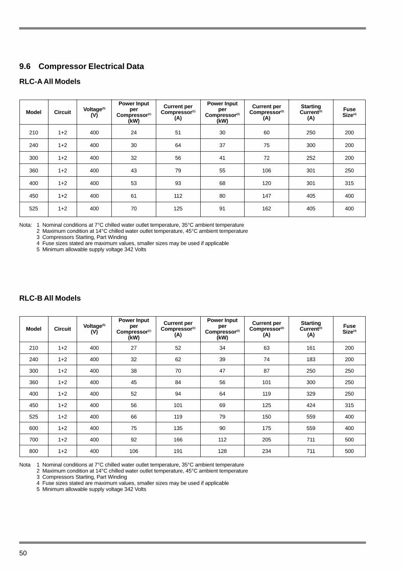
Nota: 1 Nominal conditions at 7°C chilled water outlet temperature, 35°C ambient temperature2 Maximum condition at 14°C chilled water outlet temperature, 45°C ambient temperature3 Compressors Starting, Part Winding4 Fuse sizes stated are maximum values, smaller sizes may be used if applicable5 Minimum allowable supply voltage 342 Volts
210 1+2 400 24 51 30 60 250 200
240 1+2 400 30 64 37 75 300 200
300 1+2 400 32 56 41 72 252 200
360 1+2 400 43 79 55 106 301 250
400 1+2 400 53 93 68 120 301 315
450 1+2 400 61 112 80 147 405 400
525 1+2 400 70 125 91 162 405 400
RLC-B All Models
Nota 1 Nominal conditions at 7°C chilled water outlet temperature, 35°C ambient temperature2 Maximum condition at 14°C chilled water outlet temperature, 45°C ambient temperature3 Compressors Starting, Part Winding4 Fuse sizes stated are maximum values, smaller sizes may be used if applicable5 Minimum allowable supply voltage 342 Volts
210 1+2 400 27 52 34 63 161 200
240 1+2 400 32 62 39 74 183 200
300 1+2 400 38 70 47 87 250 250
360 1+2 400 45 84 56 101 300 250
400 1+2 400 52 94 64 119 329 250
450 1+2 400 56 101 69 125 424 315
525 1+2 400 66 119 79 150 559 400
600 1+2 400 75 135 90 175 559 400
700 1+2 400 92 166 112 205 711 500
800 1+2 400 106 191 128 234 711 500
Power Input per
Compressor (1)
(kW)
Voltage (5)
(V)CircuitModelCurrent per
Compressor (1)
(A)
Power Input per
Compressor (2)
(kW)
Current perCompressor (2)
(A)
StartingCurrent (3)
(A)
FuseSize(4)
Power Input per
Compressor (1)
(kW)
Voltage (5)
(V)CircuitModelCurrent per
Compressor (1)
(A)
Power Input per
Compressor (2)
(kW)
Current perCompressor (2)
(A)
StartingCurrent (3)
(A)
FuseSize(4)
50
9.6 Compressor Electrical Data
RLC-A All Models

51
9.7 Fan Electrical Data
RLC-A All Models
RLC-A 210-300 0,9 1,95 5,9 2,9 4,8 7,6RLC-A 360-525 1,5 2,9 8,8 4,7 8,7 28
ModelStandard fans
Nominal Power(kW)
Max RunningCurrent (A)
Max StartingCurrent (A)
Nominal Power(kW)
Max RunningCurrent (A)
Max RunningCurrent (A)
High Pressure Fans
RLC-B All Models
RLC-B 210-360 0,9 1,95 5,9 2,9 4,8 7,6RLC-B 400-800 1,5 2,9 8,8 4,7 8,7 28
ModelStandard fans
Nominal Power(kW)
Max RunningCurrent (A)
Max StartingCurrent (A)
Nominal Power(kW)
Max RunningCurrent (A)
Max RunningCurrent (A)
High Pressure Fans

(1) 90 93 95 90 86 75 69 95(2) 78 81 87 83 77 67 57 87(1) 91 92 95 90 85 80 70 95(2) 78 85 88 84 77 69 58 88(1) 92 96 97 91 88 79 70 97(2) 78 87 92 85 77 69 59 90(1) 91 95 99 93 84 80 71 98(2) 80 87 94 84 77 70 60 92(1) 93 96 98 94 86 78 73 98(2) 83 91 94 87 77 67 67 93(1) 93 96 98 94 86 78 73 98(2) 86 90 94 88 74 67 67 93(1) 96 99 101 95 86 79 74 100(2) 87 93 95 89 75 68 68 94
RLC-A All models
Nota: Reference data with machine operating at nominal condition 12°/7°C chilled water1 > 38°C ambient RLC-A (Standard Version)2 < 25°C ambient RLC-A/Q (Quiet Version)
Tolerance +/- 2 dB(A)
Model125 250 500 1000 2000 4000 8000
Total dB(A)Octave Band (Hz)
210
240
300
360
400
450
525
52
9.8 Sound Power Levels
RLC-B All Models
Nota: Reference data with machine operating at nominal condition 12°/7°C chilled water1 > 38°C ambient RLC-A (Standard Version)2 < 25°C ambient RLC-A/Q (Quiet Version)
Tolerance +/- 2 dB(A)
Model125 250 500 1000 2000
Octave Band (Hz)
(1) 90 92 95 91 86 75 69 95(2) 78 83 87 83 77 67 57 87(1) 91 93 95 92 84 80 70 95(2) 78 83 88 84 76 69 59 88(1) 92 95 97 91 88 79 70 97(2) 78 87 89 86 76 69 59 89(1) 91 95 96 94 84 80 71 97(2) 80 86 90 86 76 70 60 90(1) 93 96 98 94 85 78 73 98(2) 83 88 90 89 76 67 67 91(1) 93 96 98 94 85 78 73 98(2) 86 88 91 90 74 67 67 92(1) 96 98 100 96 86 79 74 100(2) 87 90 92 90 78 68 68 93(1) 94 97 100 96 88 81 75 100(2) 87 91 93 90 85 77 70 94(1) 96 98 101 97 88 81 75 101(2) 87 92 95 92 78 72 68 95(1) 97 99 102 98 89 82 76 102(2) 88 92 95 92 88 74 71 96
210
240
300
360
400
450
525
600
700
800
4000 8000Total dB(A)
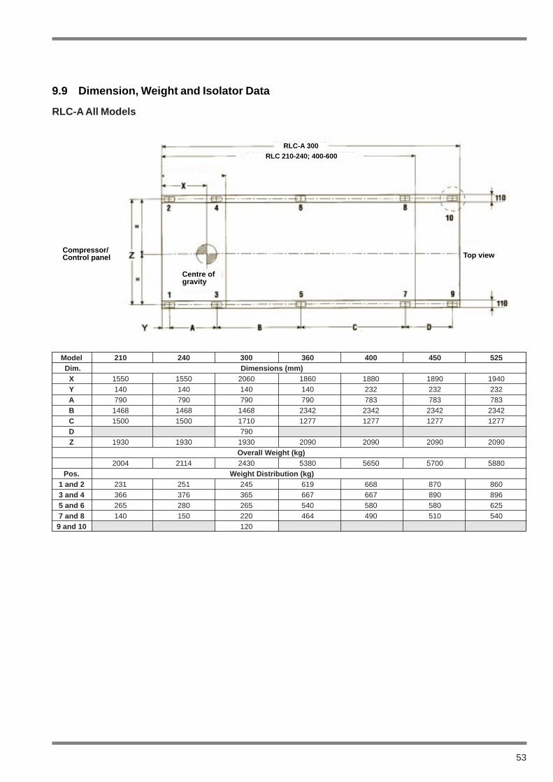
53
Model 210 240 300 360 400 450 525Dim. Dimensions (mm)
X 1550 1550 2060 1860 1880 1890 1940Y 140 140 140 140 232 232 232A 790 790 790 790 783 783 783B 1468 1468 1468 2342 2342 2342 2342C 1500 1500 1710 1277 1277 1277 1277D 790Z 1930 1930 1930 2090 2090 2090 2090
Overall Weight (kg)2004 2114 2430 5380 5650 5700 5880
Pos. Weight Distribution (kg)1 and 2 231 251 245 619 668 870 8603 and 4 366 376 365 667 667 890 8965 and 6 265 280 265 540 580 580 6257 and 8 140 150 220 464 490 510 540
9 and 10 120
RLC-A All Models
9.9 Dimension, Weight and Isolator Data
RLC-A 300RLC 210-240; 400-600
RLC-A 60-150
Compressor/Control panel Top view
Centre ofgravity
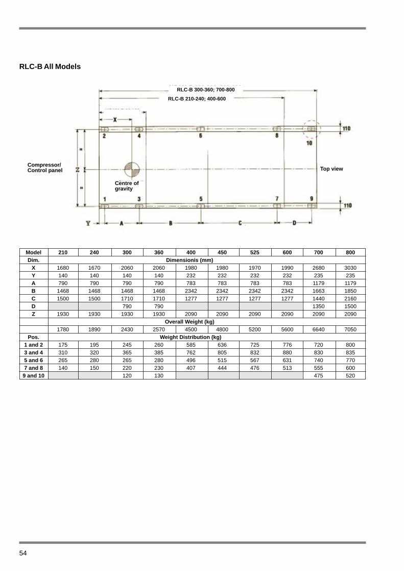
54
Model 210 240 300 360 400 450 525 600 700 800Dim. Dimensionis (mm)
X 1680 1670 2060 2060 1980 1980 1970 1990 2680 3030Y 140 140 140 140 232 232 232 232 235 235A 790 790 790 790 783 783 783 783 1179 1179B 1468 1468 1468 1468 2342 2342 2342 2342 1663 1850C 1500 1500 1710 1710 1277 1277 1277 1277 1440 2160D 790 790 1350 1500Z 1930 1930 1930 1930 2090 2090 2090 2090 2090 2090
Overall Weight (kg)1780 1890 2430 2570 4500 4800 5200 5600 6640 7050
Pos. Weight Distribution (kg)1 and 2 175 195 245 260 585 636 725 776 720 8003 and 4 310 320 365 385 762 805 832 880 830 8355 and 6 265 280 265 280 496 515 567 631 740 7707 and 8 140 150 220 230 407 444 476 513 555 600
9 and 10 120 130 475 520
RLC-B All Models
RLC-B 300-360; 700-800
RLC-B 210-240; 400-600
RLC-B 60-150
Compressor/Control panel Top view
Centre ofgravity
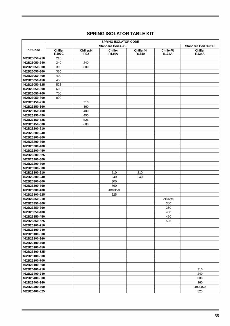
55
SPRING ISOLATOR TABLE KIT
462B26050-210 210462B26050-240 240 240462B26050-300 300 300462B26050-360 360462B26050-400 400462B26050-450 450462B26050-525 525462B26050-600 600462B26050-700 700462B26050-800 800462B26150-210 210462B26150-360 360462B26150-400 400462B26150-450 450462B26150-525 525462B26150-600 600462B26200-210462B26200-240462B26200-300462B26200-360462B26200-400462B26200-450462B26200-525462B26200-600462B26200-700462B26200-800462B26300-210 210 210462B26300-240 240 240462B26300-300 300462B26300-360 360462B26300-400 400/450462B26300-525 525462B26350-210 210/240462B26350-300 300462B26350-360 360462B26350-400 400462B26350-450 450462B26350-525 525462B26100-210462B26100-240462B26100-300462B26100-360462B26100-400462B26100-450462B26100-525462B26100-600462B26100-700462B26100-800462B26400-210 210462B26400-240 240462B26400-300 300462B26400-360 360462B26400-400 400/450462B26400-525 525
Kit Code
SPRING ISOLATOR CODEStandard Coil Al/Cu
ChillerR407C
Chiller/HR22
ChillerR134A
Chiller/HR134A
Chiller/RR134A
ChillerR134A
Standard Coil Cu/Cu

56
RLC, RLC-A and RLC-B Models 210 to 240
9.10 Piping and Instrumentation Diagrams
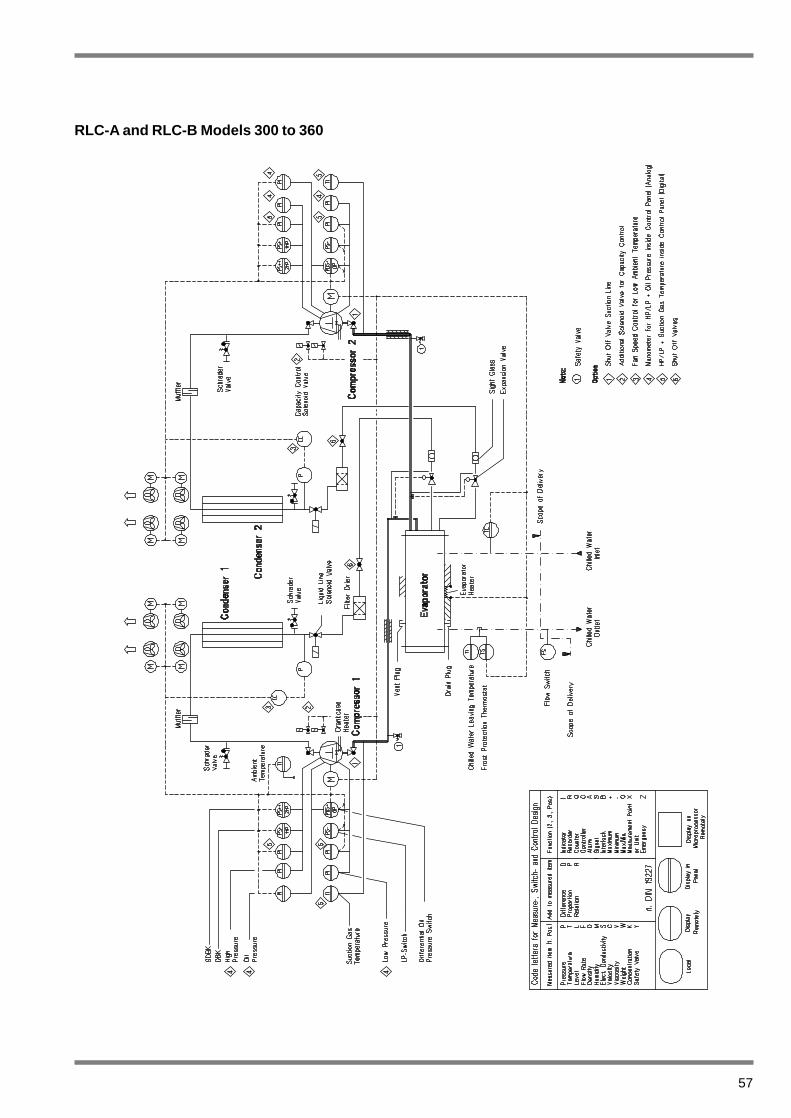
57
RLC-A and RLC-B Models 300 to 360
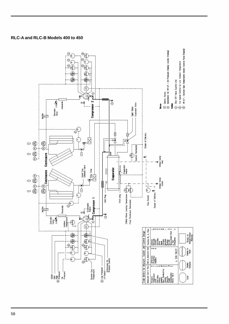
58
RLC-A and RLC-B Models 400 to 450

59
RLC-A Model 525 and RLC-B Models 525 to 800
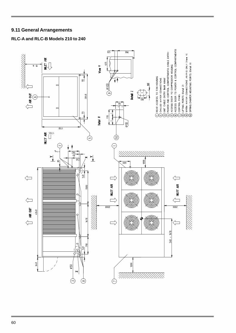
60
RLC-A and RLC-B Models 210 to 240
9.11 General Arrangements
1785
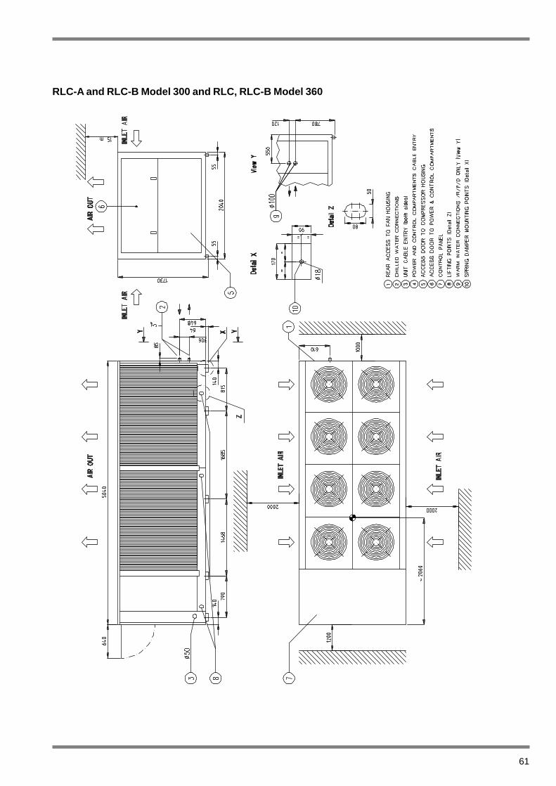
61
RLC-A and RLC-B Model 300 and RLC, RLC-B Model 360

62
RLC-A Model 360 and RLC and RLC-B Models 400 to 450

63
RLC-A Model 525 and RLC-B Models 525 to 600
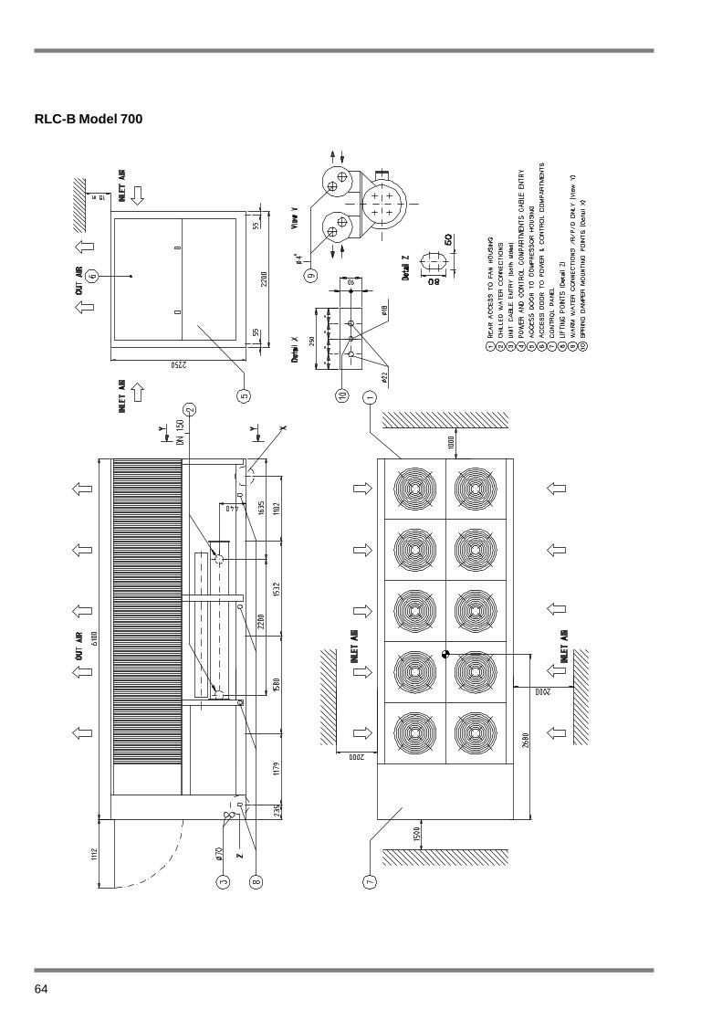
64
RLC-B Model 700
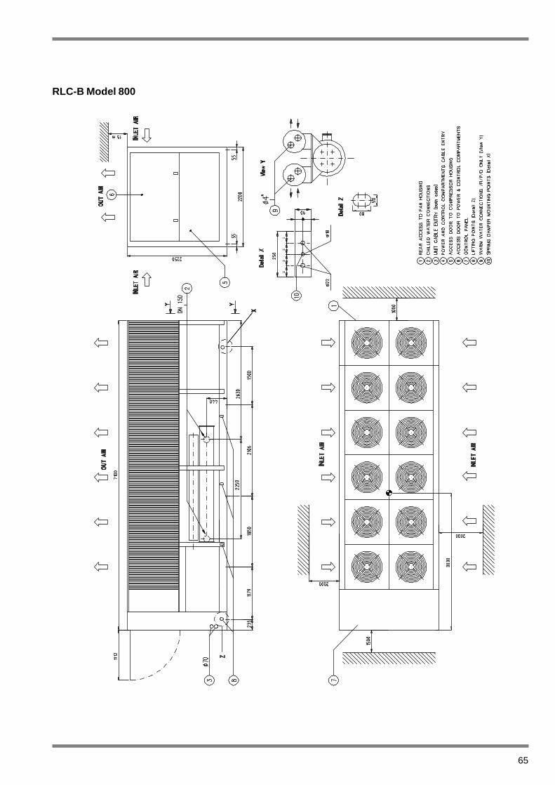
65
RLC-B Model 800
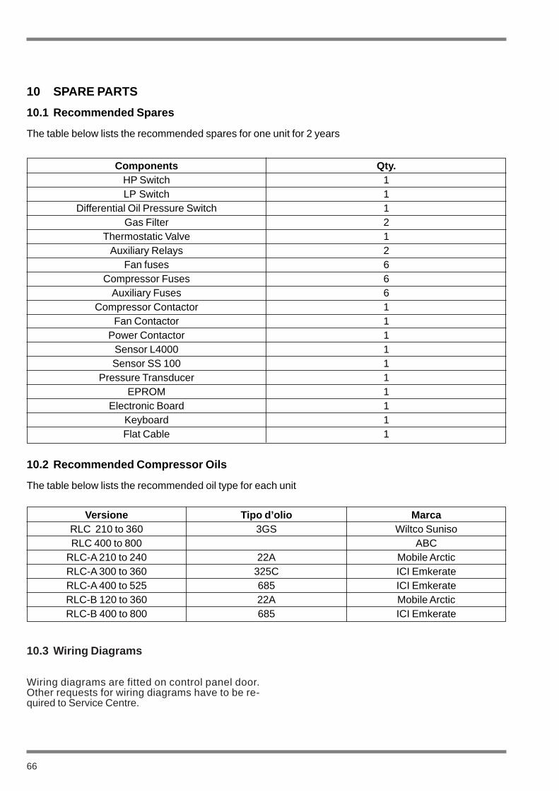
Wiring diagrams are fitted on control panel door.Other requests for wiring diagrams have to be re-quired to Service Centre.
10.3 Wiring Diagrams
66
10 SPARE PARTS
10.1 Recommended Spares
The table below lists the recommended spares for one unit for 2 years
Components Qty.HP Switch 1LP Switch 1
Differential Oil Pressure Switch 1Gas Filter 2
Thermostatic Valve 1Auxiliary Relays 2
Fan fuses 6Compressor Fuses 6
Auxiliary Fuses 6Compressor Contactor 1
Fan Contactor 1Power Contactor 1
Sensor L4000 1Sensor SS 100 1
Pressure Transducer 1EPROM 1
Electronic Board 1Keyboard 1Flat Cable 1
10.2 Recommended Compressor Oils
The table below lists the recommended oil type for each unit
Versione Tipo d’olio MarcaRLC 210 to 360 3GS Wiltco SunisoRLC 400 to 800 ABC
RLC-A 210 to 240 22A Mobile ArcticRLC-A 300 to 360 325C ICI EmkerateRLC-A 400 to 525 685 ICI EmkerateRLC-B 120 to 360 22A Mobile ArcticRLC-B 400 to 800 685 ICI Emkerate

67
11 DE-COMMISSIONIG,DISMANTLING AND DISPOSAL
Never release refrigerant to the atmo-sphere when emptying the refrigeratingcircuits. Suitable retrieval equipmentmust be used. If reclaimed refrigerantcannot be re-used. It must be returnedto the manufacturer.
Never discard used compressor oil, asit contains refrigerant in solution. Re-turn used oil to the oil manufacturer.
Unless otherwise indicated, the operations descri-bed below can be performed by any properly trai-ned maintenance technician.
11.1 General
Isolate all sources of electrical supply to the unit in-cluding any control system supplies switched by theunit. Ensure that all points of isolation are securedin the ‘OFF’ position. The supply cables may thenbe disconnected and removed. For connectionpoints refer to Section 4.
Remove all refrigerant from each system of the unitinto a suitable container using a refrigerant reclaimor recovery unit. This refrigerant may then be reu-sed, if appropriate, or returned to the manufacturerfor disposal. Under NO circumstances should refri-gerant be vented to atmosphere. Drain the refrige-rant oil from each system into a suitable containerand dispose of according to local laws and regula-tions governing the disposal of oily wastes. Any spiltoil should be mopped up and similarly disposed of.
Isolate the unit heat exchanger(s) from all externalwater systems and drain the heat exchanger sec-tion( s) of the system. If no isolation valves are in-stalled it may be necessary to drain the completesystem(s).
If glycol or similar solutions have beenused in the water system(s), or chemi-cal additives are contained, the solu-tion mUST be disposed of in a suitableand safe manner. Under NO circum-stances should any system containingglycol or similar solutions be draineddirectly into domestic waste or naturalwater systems.
After draining, the water pipework can be discon-nected and removed.
Packaged units can generally be removed in onepiece after disconnection as above. Any fixing downbolts should be removed and then the unit shouldbe lifted from position using the points provided andequipment of adequate lifting capacity.
Reference should be made to Section 4 for unit in-stallation instructions, Section 9 for unit weightsand Section 3 for handling.
Units which cannot be removed in one piece afterdisconnection as above, must be dismantled in po-sition. special care should be taken regarding theweight and the handling of each component. Wherepossible units should be dismantled in the reverseorder of installation.
Residual refrigerant oil and glycol or si-milar solutions may remain in someparts of the system. These should bemopped up and disposed of as descri-bed above.
It is important to ensure that whilst components arebeing removed the remaining parts are supportedin a safe manner.
Only use lifting equipment of adequatecapacity.
After removal from position the unit parts may be di-sposed of according to local laws and regulations.
WARNING
WARNING
WARNING
WARNING
WARNING