AIR-COOLED CONDENSING UNITS with BITZER COMPRESSORS
24
AIR-COOLED CONDENSING UNITS with BITZER COMPRESSORS Technical Guide BN-CUBZTB April 2011
Transcript of AIR-COOLED CONDENSING UNITS with BITZER COMPRESSORS
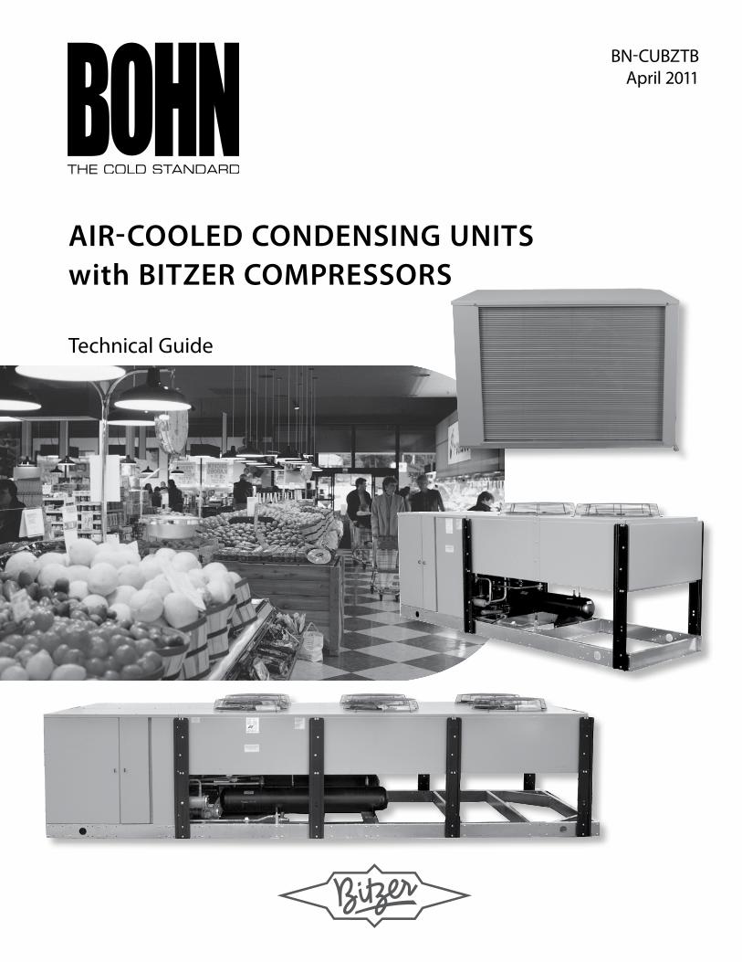
air-cooled condensing unitswith Bitzer compressors
Technical Guide
bn-CUbZTbApril 2011
2© 2011 Heatcraft Refrigeration Products, LLC
Floating Tube™ Coil 3Options 4-5Limitizer® 6Bitzer Compressor Features and Benefits 7-8
Horizontal Air Discharge Condensing Units 4 to 13 HP Standard and Optional Features 9
Nomenclature 9
Performance Data Medium Temperature - R-404A/R-507 10 Low Temperature - R-404A/R-507 10
Electrical Data Medium Temperature - R-404A/R-507 11 Low Temperature - R-404A/R-507 11
Specifications and Dimensional Data Medium Temperature - R-404A/R-507 12 Low Temperature - R-404A/R-507 12
Vertical Air Discharge Condensing Units 13 to 50 HP, Single Compressor
Standard and Optional Features 13
Nomenclature 13
Performance Data Medium Temperature - R-404A/R-507 14 Low Temperature - R-404A/R-507 15
Electrical Data Medium Temperature - R-404A/R-507 16 Low Temperature - R-404A/R-507 16
Specifications and Dimensional Data Medium Temperature - R-404A/R-507 17 Low Temperature - R-404A/R-507 17
Vertical Air Discharge Condensing Units 26 to 100 HP, Dual Compressor Standard and Optional Features 18
Nomenclature 18
Performance Data Medium Temperature - R-404A/R-507 19 Low Temperature - R-404A/R-507 20
Electrical Data Medium Temperature - R-404A/R-507 21 Low Temperature - R-404A/R-507 21
Specifications and Dimensional Data Medium Temperature - R-404A/R-507 22 Low Temperature - R-404A/R-507 22
Table of Contents
3
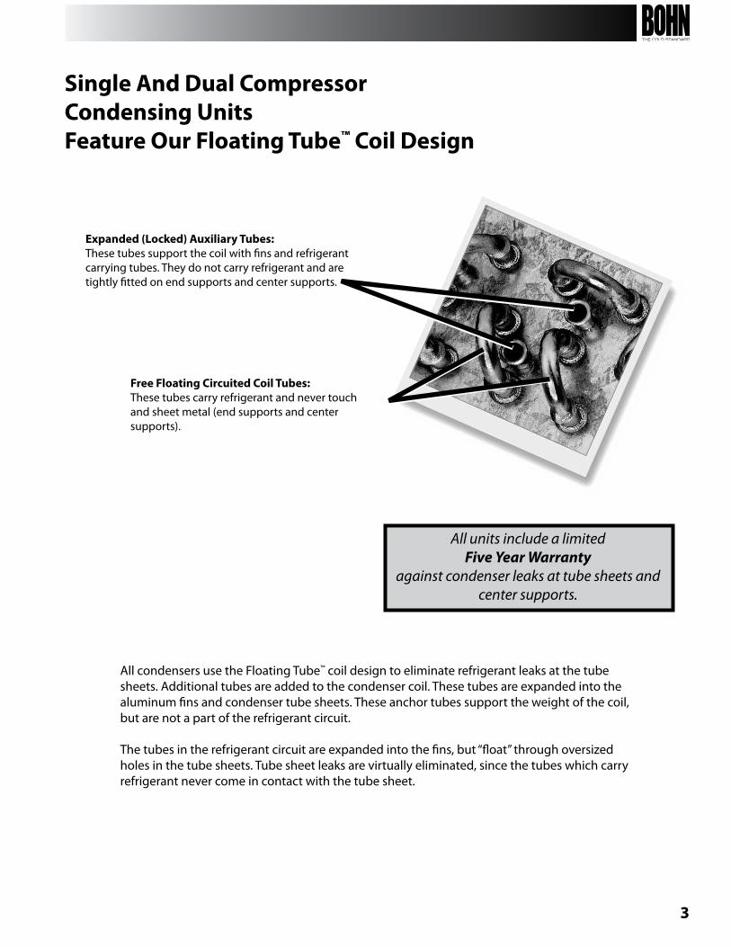
Expanded (Locked) Auxiliary Tubes: These tubes support the coil with fins and refrigerant carrying tubes. They do not carry refrigerant and are tightly fitted on end supports and center supports.
Free Floating Circuited Coil Tubes: These tubes carry refrigerant and never touch and sheet metal (end supports and center supports).
All condensers use the Floating Tube™ coil design to eliminate refrigerant leaks at the tube sheets. Additional tubes are added to the condenser coil. These tubes are expanded into the aluminum fins and condenser tube sheets. These anchor tubes support the weight of the coil, but are not a part of the refrigerant circuit.
The tubes in the refrigerant circuit are expanded into the fins, but “float” through oversized holes in the tube sheets. Tube sheet leaks are virtually eliminated, since the tubes which carry refrigerant never come in contact with the tube sheet.
All units include a limited Five Year Warranty
against condenser leaks at tube sheets and center supports.
Single And Dual Compressor Condensing Units Feature Our Floating Tube™ Coil Design
4
Available with Beacon II™
beacon II™ is the next generation of bohn’s patented, preassembled, factory installed refrigeration system featuring an integrated microcomputer-based electronic control board. The beacon II™ systems come completely factory installed, wired and tested saving you time and money.
Beacon II™ offers:• Complete factory installation, wiring and testing which saves time and money• Simple field electrical connections and 24 volt wiring between condensing and evaporator units• Preset factory superheat allowing the system to run more efficiently and reducing future adjustments• Monitors and controls box temperature, evaporator superheat, condenser fan cycling on two fan units, system status and defrost from outside the box• Monitor and make system changes remotely via modem and exclusive beacon II™ Smart II software• Data logging capabilities with Smart Controller
Beacon II™ Smart Controllerbeacon II™ Smart Controller is an optional system monitoring and programming control device. It allows for adjustments to be made at the push of a button from a conveniently mounted location. The beacon II™ Smart Controller also allows you to monitor and make changes to the refrigeration system via modem connection from anywhere in the world. The beacon II™ has been updated to allow the user to make even more precise adjustments than the original beacon’s Smart Controller. One Smart Controller can program and control up to four separate condensing units with up to four evaporators on each system. That’s more control in your hands!
™
E Solutions branded products and options are designed to exceed current energy and environmental standards. It is our commitment in environmental innovation to dedicate ourselves by delivering energy efficient eco-conscious choices. Products included in the E Solutions portfolio reduce costs, improve bottom lines, and enhance equipment performance and service life.
The beacon II™ Refrigeration System with Smart Defrost, and the factory-installed Smart Defrost Kit™ are E Solutions options that will optimize your savings and increase energy efficiency.
Options
5
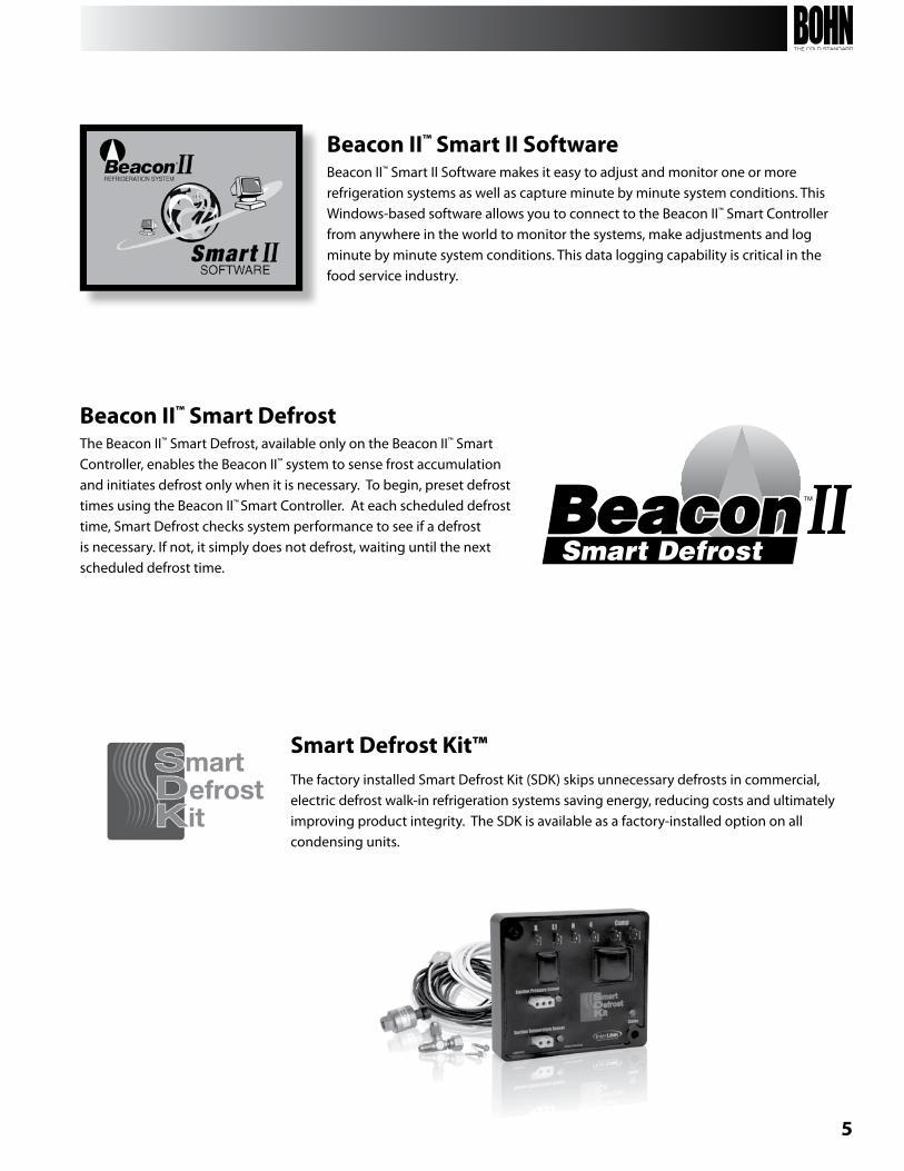
Beacon II™ Smart II Softwarebeacon II™ Smart II Software makes it easy to adjust and monitor one or more refrigeration systems as well as capture minute by minute system conditions. This Windows-based software allows you to connect to the beacon II™ Smart Controller from anywhere in the world to monitor the systems, make adjustments and log minute by minute system conditions. This data logging capability is critical in the food service industry.
Beacon II™ Smart DefrostThe beacon II™ Smart Defrost, available only on the beacon II™ Smart Controller, enables the beacon II™ system to sense frost accumulation and initiates defrost only when it is necessary. To begin, preset defrost times using the beacon II™ Smart Controller. At each scheduled defrost time, Smart Defrost checks system performance to see if a defrost is necessary. If not, it simply does not defrost, waiting until the next scheduled defrost time.
Smart Defrost Kit™The factory installed Smart Defrost Kit (SDK) skips unnecessary defrosts in commercial, electric defrost walk-in refrigeration systems saving energy, reducing costs and ultimately improving product integrity. The SDK is available as a factory-installed option on all condensing units.
6
The Need For Head Pressure ControlRefrigeration condensing units must efficiently perform at varying ambient conditions. A properly sized unit will adequately perform at even the highest summer ambient temperatures. However, in situations where the system must operate the majority of the time at less than design temperature, a means of providing adequate head pressure for refrigerant flow is desirable.
The Bohn Limitizer® SystemThe Limitizer® system is a factory assembled system utilizing a Limitizer® control to maintain a constant head pressure at the air cooled condensing unit during all climatic conditions when the ambient temperature drops below 75°F (typical).
When the ambient is above 75°F, the condenser pressure is above the Limitizer® valve setting and therefore, the valve remains in the full open position.
As the temperature drops below 75°F, the pressure at the condenser also drops below the setting of the Limitizer® valve. The Limitizer® valve, sensing the reduction in condensing pressure, modulates toward the closed position, thus restricting the flow of liquid from the condenser. The liquid backs up into the condenser and floods a portion of the tubes, thus reducing the overall capacity of the condenser. The Limitizer® valve will continue to flood the condenser until the pressure setting has been reached, thus providing proper head pressure at all ambient temperatures.
While the condenser floods, a second line pressurizes the receiver through another valve. Therefore, the refrigerant flow from the condenser to the receiver modulates with conditions. However, the bypass from the discharge line maintains a minimum receiver pressure. These valves are adjustable and the minimum receiver pressure may be reset higher or lower depending upon application situations of a particular job. The Limitizer® system uses this two-valve, adjustable design.
LIMITIZER®
7
bitzer is the world’s largest manufacturer of semi-hermetic refrigeration compressors over 3 HP. In business since 1934, bitzer has manufacturing plants in Germany, brazil, Portugal, China and the United States and operates in over 100 countries around the world. bitzer’s Georgia plant manufactures a complete range of semi-hermetic compressors from 3 to 50 HP. bitzer provides aftermarket support through wholesalers and also provides 24-hour replacement service from its seven distribution warehouses located across the U.S.
Bitzer Offers:
• 1-Year Warranty• Unloader Heads Standard on All 4 & 6-cylinder Models• Dual Voltage Control Modules on All Models• Dual Voltage Compressors (6 to 50 HP)• Lowest Sound Levels in their Class (built-in Mufflers)• Superior Lubrication and Low Oil Circulation Rates• German Engineering / built in America
Bitzer Standard Execution Octagon4C Models
4B & 6BModels
POE Oil Charge √ √
Protective Dry-nitrogen Charge √ √
Suction & Discharge Service Valves √ √
Dual Voltage InT Protection Modules √ √
Terminal box Enclosure Class IP65 √ √
Unloader Heads √ √
Patented Internal Mufflers √ √
Centrifugal Oil System √ √
Conventional Oil Pump √ √
Bitzer Options 4C Models 4B & 6B
Mounting Hardware (Spring Kits) √ √
Hard Mount Kits √ √
Optical Oil Sensor √ √
Crankcase Heaters √ √
Unloader Stems / Coils √ √
Head Fans and brackets √ √
Delta P II Differential Oil Pres. Switch √ √
Bitzer Quiet!!!
bitzer compressors are famous for their low sound levels. We change capacities within a frame size by changing our bore diameters rather than the length of the piston strokes. This gives our compressors an unsurpassed balance and precision that translates to low decibels. In addition, bitzer compressors have a muffler built into each head (see photo) that eliminates pulsations and reduces the sound levels even further.
Bitzer Compressors Features and Benefits
8
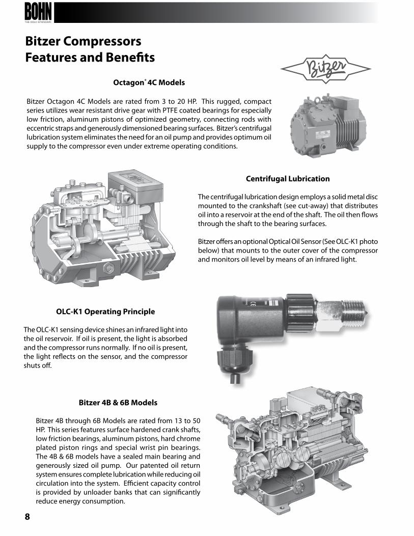
Octagon® 4C Models
bitzer Octagon 4C Models are rated from 3 to 20 HP. This rugged, compact series utilizes wear resistant drive gear with PTFE coated bearings for especially low friction, aluminum pistons of optimized geometry, connecting rods with eccentric straps and generously dimensioned bearing surfaces. bitzer’s centrifugal lubrication system eliminates the need for an oil pump and provides optimum oil supply to the compressor even under extreme operating conditions.
Centrifugal Lubrication
The centrifugal lubrication design employs a solid metal disc mounted to the crankshaft (see cut-away) that distributes oil into a reservoir at the end of the shaft. The oil then flows through the shaft to the bearing surfaces.
bitzer offers an optional Optical Oil Sensor (See OLC-K1 photo below) that mounts to the outer cover of the compressor and monitors oil level by means of an infrared light.
OLC-K1 Operating Principle
The OLC-K1 sensing device shines an infrared light into the oil reservoir. If oil is present, the light is absorbed and the compressor runs normally. If no oil is present, the light reflects on the sensor, and the compressor shuts off.
Bitzer 4B & 6B Models
bitzer 4b through 6b Models are rated from 13 to 50 HP. This series features surface hardened crank shafts, low friction bearings, aluminum pistons, hard chrome plated piston rings and special wrist pin bearings. The 4b & 6b models have a sealed main bearing and generously sized oil pump. Our patented oil return system ensures complete lubrication while reducing oil circulation into the system. Efficient capacity control is provided by unloader banks that can significantly reduce energy consumption.
Bitzer Compressors Features and Benefits
9
Hor
izon
tal D
isch
arge
Nomenclature
B B T 0000 L 6 C
Brand Compressor Application Horsepower Temp. Range Refrigerant Voltageb = bohn b = bitzer T = Outdoor
n = IndoorS = beacon II™
0401 - 40551 - 50601 - 60611 -6
0751 - 7.50901 - 9
1001 - 101201 - 121301 - 13
M = Med. Temp.L = Low Temp.
6 = R-404A, R-507
C = 208-230/3/60D = 460/3/60E = 575/3/60
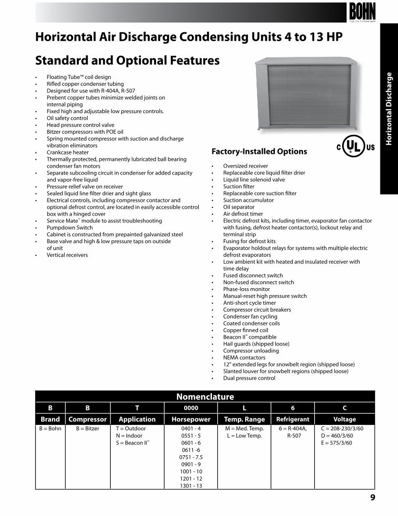
Horizontal Air Discharge Condensing Units 4 to 13 HP
Standard and Optional Features• Floating Tube™ coil design• Rifled copper condenser tubing• Designed for use with R-404A, R-507• Prebent copper tubes minimize welded joints on
internal piping• Fixed high and adjustable low pressure controls.• Oil safety control• Head pressure control valve• bitzer compressors with POE oil• Spring mounted compressor with suction and discharge
vibration eliminators• Crankcase heater• Thermally protected, permanently lubricated ball bearing
condenser fan motors• Separate subcooling circuit in condenser for added capacity
and vapor-free liquid• Pressure relief valve on receiver• Sealed liquid line filter drier and sight glass• Electrical controls, including compressor contactor and
optional defrost control, are located in easily accessible control box with a hinged cover
• Service Mate™ module to assist troubleshooting• Pumpdown Switch• Cabinet is constructed from prepainted galvanized steel• base valve and high & low pressure taps on outside
of unit• Vertical receivers
Factory-Installed Options
• Oversized receiver• Replaceable core liquid filter drier• Liquid line solenoid valve• Suction filter• Replaceable core suction filter• Suction accumulator• Oil separator• Air defrost timer• Electric defrost kits, including timer, evaporator fan contactor
with fusing, defrost heater contactor(s), lockout relay and terminal strip
• Fusing for defrost kits• Evaporator holdout relays for systems with multiple electric
defrost evaporators• Low ambient kit with heated and insulated receiver with
time delay• Fused disconnect switch• non-fused disconnect switch• Phase-loss monitor• Manual-reset high pressure switch• Anti-short cycle timer• Compressor circuit breakers• Condenser fan cycling• Coated condenser coils• Copper finned coil• beacon II™ compatible• Hail guards (shipped loose) • Compressor unloading• nEMA contactors• 12" extended legs for snowbelt region (shipped loose)• Slanted louver for snowbelt regions (shipped loose)• Dual pressure control
10
3 - 22 HP Condensing U
nitsH
orizontal Discharge
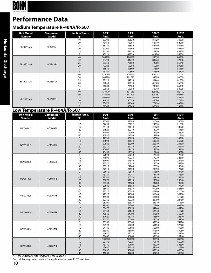
Medium Temperature R-404A/R-507
*= T for Outdoors, n for Indoors, S for beacon II™
Consult factory on all models for applications above 110°F ambient.
Unit ModelNumber
CompressorModel
Suction Temp. 90°FAmb.
95°F Amb.
100°F Amb.
110°F Amb.°F
bb*0551M6 4C0969SH
40302520155
89700 75460 68740 62260 56190 45520
85620 72064 65580 59360 53510 43270
81720 68710 62440 56460 50870 41170
74280 62010 56230 50730 45720 36550
bb*0751M6 4C1145SH
40302520155
1052808872080750727806564053140
1006908473976660693606250050500
955308027072960659605938047880
869607238065640592105316042700
bb*0901M6 4C1385SH
40302520155
12909010878099120898508120065960
12413010162394750858707750062760
1187009939090440818607380059840
1072209005081730767506634053950
bb*1001M6 4C1480PH
40302520155
137470115200104860949308567069300
131010107509100040905508156065840
12508010543095260860907745062560
1137509463085740771306951055590
Performance Data
Unit ModelNumber
CompressorModel
Suction Temp. 90°FAmb.
95°F Amb.
100°F Amb.
110°F Amb.°F
bb*0401L6 4C0969SL
0 35200 33380 31560 28020-10 27690 26222 24690 21680-15 24440 23040 21620 18870-20 21520 20210 18930 16460-30 17090 16000 14930 12820-40 15030 14090 13200 11330
bb*0551L6 4C1145SL
0 42930 40770 38600 34290-10 33890 32073 30230 26620-15 29880 28200 26510 23190-20 26310 24770 23230 20270-30 20960 19650 18370 15830-40 18450 17320 16240 14010
bb*0601L6 4C1385SL
0 52890 50250 47530 42230-10 41590 39334 37070 32610-15 36690 34580 32480 28460-20 32320 30410 28510 24810-30 25910 24260 22630 19540-40 22910 21500 20090 17370
bb*0611L6 4C1480PL
0 56010 52610 49660 43790-10 43740 41241 38770 33850-15 38540 36230 33910 29460-20 33870 31750 29680 25640-30 26730 24980 23280 19980-40 23080 21650 20230 17430
bb*0751L6 4C1761PL
0 68040 64570 61090 54180-10 53710 50780 47800 41660-15 47320 44580 41840 36480-20 41590 39080 36600 31870-30 32760 30720 28700 24750-40 28200 26530 24910 21590
bb*1001L6 4C2067PL
0 78200 74200 70160 63210-10 61470 58050 54740 48110-15 54150 51030 47940 41820-20 47560 44700 41880 36370-30 37620 35240 32860 28310-40 32550 30500 28620 24710
bb*1201L6 4C2397PL
0 93390 88580 83830 74420-10 74920 69208 65150 57070-15 64440 60680 56890 49580-20 56560 53090 49680 43080-30 44620 41750 38850 33170-40 38400 36060 33630 28760
bb*1301L6 4b2707PL
0 105360 100530 95590 85790-10 83410 79221 75110 66870-15 73740 69890 66030 58590-20 65040 61530 58040 51230-30 51830 48880 45950 40350-40 45050 42600 40250 35390
Low Temperature R-404A/R-507
11
Hor
izon
tal D
isch
arge
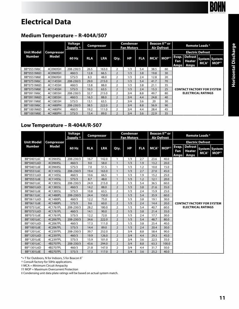
Low Temperature – R-404A/R-507
Medium Temperature – R-404A/507
*= T for Outdoors, n for Indoors, S for beacon II™
^ Consult factory for 50Hz applications.† MCA = Minimum Circuit Ampacity†† MOP = Maximum Overcurrent Protection‡ Condensing unit data plate ratings will be based on actual system match.
Electrical Data
Unit ModelNumber
CompressorModel
VoltageSupply ^ Compressor Condenser
Fan MotorsBeacon II™ or
Air Defrost Remote Loads ‡
60 Hz RLA LRA Qty. HP FLA MCA† MOP††
Electric DefrostEvap.Fan
Amps
DefrostHeater Amps
System MCA†
System MOP††
bb*0551M6C 4C0969SH 208-230/3 26.5 163.0 2 1/3 5.4 38.5 60
CONTACT FACTORY FOR SYSTEM ELECTRICAL RATINgS
bb*0551M6D 4C0969SH 460/3 12.8 66.5 2 1/3 3.8 19.8 30bb*0551M6E 4C0969SH 575/3 8.3 48.0 2 1/3 2.4 12.8 20bb*0751M6C 4C1145SH 208-230/3 29.0 215.0 2 1/3 5.4 41.7 70bb*0751M6D 4C1145SH 460/3 13.8 88.0 2 1/3 3.8 21.1 35bb*0751M6E 4C1145SH 575/3 10.3 63.5 2 1/3 2.4 15.3 25bb*0911M6C 4C1385SH 208-230/3 32.7 215.0 2 3/4 8.8 49.7 80bb*0911M6D 4C1385SH 460/3 16.3 88.0 2 3/4 4.4 24.8 40bb*0911M6E 4C1385SH 575/3 13.1 63.5 2 3/4 3.6 20 30bb*1001M6C 4C1480PH 208-230/3 38.5 222.0 2 3/4 8.8 56.9 90bb*1001M6D 4C1480PH 460/3 19.2 111.0 2 3/4 4.4 28.4 45bb*1001M6E 4C1480PH 575/3 15.4 89.0 2 3/4 3.6 22.9 35
Unit Model Number
CompressorModel
VoltageSupply ^ Compressor Condenser
Fan MotorsBeacon II™ or
Air Defrost Remote Loads ‡
60 Hz RLA LRA Qty. HP FLA MCA† MOP††
Electric DefrostEvap.Fan
Amps
DefrostHeater Amps
System MCA†
System MOP††
bb*0401L6C 4C0969SL 208-230/3 16.7 142.0 1 1/3 2.7 23.6 40.0
CONTACT FACTORY FOR SYSTEM ELECTRICAL RATINgS
bb*0401L6D 4C0969SL 460/3 9.0 58.0 1 1/3 1.9 13.2 20.0bb*0401L6E 4C0969SL 575/3 7.0 51.5 1 1/3 1.2 10.0 15.0bb*0551L6C 4C1145SL 208-230/3 19.4 163.0 1 1/3 2.7 27.0 45.0bb*0551L6D 4C1145SL 460/3 10.6 66.5 1 1/3 1.9 15.2 25.0bb*0551L6E 4C1145SL 575/3 8.7 48.0 1 1/3 1.2 12.1 20.0bb*0601L6C 4C1385SL 208-230/3 24.9 215.0 2 1/3 5.4 36.5 60.0bb*0601L6D 4C1385SL 460/3 14.2 88.0 2 1/3 3.8 21.6 35.0bb*0601L6E 4C1385SL 575/3 10.8 63.5 2 1/3 2.4 15.9 25.0bb*0611L6C 4C1480PL 208-230/3 24.4 150.0 2 1/3 5.4 35.9 60.0bb*0611L6D 4C1480PL 460/3 12.2 75.0 2 1/3 3.8 19.1 30.0bb*0611L6E 4C1480PL 575/3 9.6 60.0 2 1/3 2.4 14.4 20.0bb*0751L6C 4C1761PL 208-230/3 28.2 180.0 2 1/3 5.4 40.7 60.0bb*0751L6D 4C1761PL 460/3 14.1 90.0 2 1/3 3.8 21.4 35.0bb*0751L6E 4C1761PL 575/3 12.2 72.0 2 1/3 2.4 17.7 30.0bb*1001L6C 4C2067PL 208-230/3 34.6 222.0 2 1/3 5.4 48.7 80.0bb*1001L6D 4C2067PL 460/3 17.3 111.0 2 1/3 3.8 25.4 40.0bb*1001L6E 4C2067PL 575/3 14.4 89.0 2 1/3 2.4 20.4 30.0bb*1201L6C 4C2397PL 208-230/3 39.7 252.0 2 3/4 8.8 58.4 90.0bb*1201L6D 4C2397PL 460/3 19.9 126.0 2 3/4 4.4 29.3 45.0bb*1201L6E 4C2397PL 575/3 15.9 101.0 2 3/4 3.6 22.5 35.0bb*1301L6C 4b2707PL 208-230/3 43.6 294.0 2 3/4 8.8 63.3 100.0bb*1301L6D 4b2707PL 460/3 21.8 147.0 2 3/4 4.4 31.7 50.0bb*1301L6E 4b2707PL 575/3 17.3 117.0 2 3/4 3.6 25.2 40.0
12
3 - 22 HP Condensing U
nitsH
orizontal Discharge
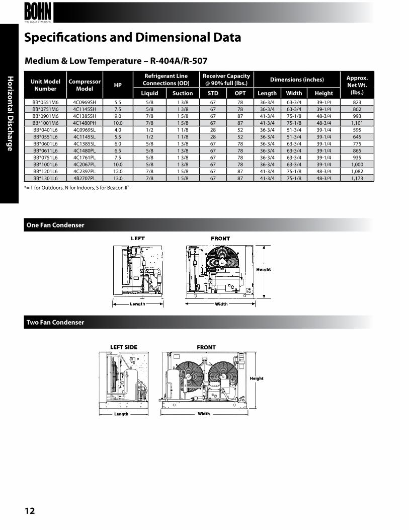
Medium & Low Temperature – R-404A/R-507
Specifications and Dimensional Data
Unit ModelNumber
CompressorModel HP
Refrigerant Line Connections (OD)
Receiver Capacity @ 90% full (lbs.) Dimensions (inches) Approx.
Net Wt. (lbs.)Liquid Suction STD OPT Length Width Height
bb*0551M6 4C0969SH 5.5 5/8 1 3/8 67 78 36-3/4 63-3/4 39-1/4 823bb*0751M6 4C1145SH 7.5 5/8 1 3/8 67 78 36-3/4 63-3/4 39-1/4 862bb*0901M6 4C1385SH 9.0 7/8 1 5/8 67 87 41-3/4 75-1/8 48-3/4 993bb*1001M6 4C1480PH 10.0 7/8 1 5/8 67 87 41-3/4 75-1/8 48-3/4 1,101bb*0401L6 4C0969SL 4.0 1/2 1 1/8 28 52 36-3/4 51-3/4 39-1/4 595bb*0551L6 4C1145SL 5.5 1/2 1 1/8 28 52 36-3/4 51-3/4 39-1/4 645bb*0601L6 4C1385SL 6.0 5/8 1 3/8 67 78 36-3/4 63-3/4 39-1/4 775bb*0611L6 4C1480PL 6.5 5/8 1 3/8 67 78 36-3/4 63-3/4 39-1/4 865bb*0751L6 4C1761PL 7.5 5/8 1 3/8 67 78 36-3/4 63-3/4 39-1/4 935bb*1001L6 4C2067PL 10.0 5/8 1 3/8 67 78 36-3/4 63-3/4 39-1/4 1,000bb*1201L6 4C2397PL 12.0 7/8 1 5/8 67 87 41-3/4 75-1/8 48-3/4 1,082bb*1301L6 4b2707PL 13.0 7/8 1 5/8 67 87 41-3/4 75-1/8 48-3/4 1,173
One Fan Condenser
LEFT SIDE FRONT
Length Width
Height
Two Fan Condenser
*= T for Outdoors, n for Indoors, S for beacon II™
13
Sing
le V
erti
cal A
ir D
isch
arge
Con
dens
ing
Uni
t
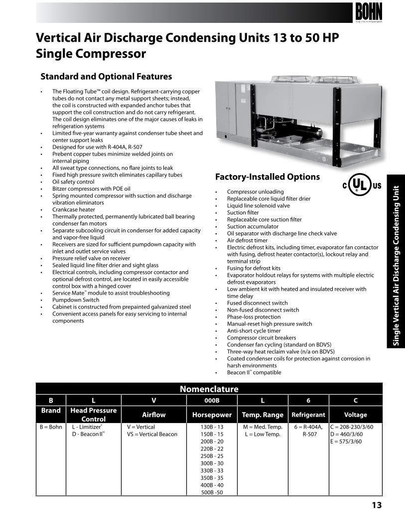
Standard and Optional Features• The Floating Tube™ coil design. Refrigerant-carrying copper
tubes do not contact any metal support sheets; instead, the coil is constructed with expanded anchor tubes that support the coil construction and do not carry refrigerant. The coil design eliminates one of the major causes of leaks in refrigeration systems
• Limited five-year warranty against condenser tube sheet and center support leaks
• Designed for use with R-404A, R-507• Prebent copper tubes minimize welded joints on
internal piping• All sweat type connections, no flare joints to leak• Fixed high pressure switch eliminates capillary tubes• Oil safety control• bitzer compressors with POE oil• Spring mounted compressor with suction and discharge
vibration eliminators• Crankcase heater• Thermally protected, permanently lubricated ball bearing
condenser fan motors• Separate subcooling circuit in condenser for added capacity
and vapor-free liquid• Receivers are sized for sufficient pumpdown capacity with
inlet and outlet service valves• Pressure relief valve on receiver• Sealed liquid line filter drier and sight glass• Electrical controls, including compressor contactor and
optional defrost control, are located in easily accessible control box with a hinged cover
• Service Mate™ module to assist troubleshooting• Pumpdown Switch• Cabinet is constructed from prepainted galvanized steel• Convenient access panels for easy servicing to internal
components
Factory-Installed Options• Compressor unloading• Replaceable core liquid filter drier• Liquid line solenoid valve• Suction filter• Replaceable core suction filter• Suction accumulator• Oil separator with discharge line check valve• Air defrost timer• Electric defrost kits, including timer, evaporator fan contactor
with fusing, defrost heater contactor(s), lockout relay and terminal strip
• Fusing for defrost kits• Evaporator holdout relays for systems with multiple electric
defrost evaporators• Low ambient kit with heated and insulated receiver with
time delay• Fused disconnect switch• non-fused disconnect switch• Phase-loss protection• Manual-reset high pressure switch• Anti-short cycle timer• Compressor circuit breakers• Condenser fan cycling (standard on bDVS)• Three-way heat reclaim valve (n/a on bDVS)• Coated condenser coils for protection against corrosion in
harsh environments• beacon II™ compatible
Vertical Air Discharge Condensing Units 13 to 50 HPSingle Compressor
NomenclatureB L V 000B L 6 C
Brand Head Pressure Control Airflow Horsepower Temp. Range Refrigerant Voltage
b = bohn L - Limitizer®
D - beacon II™V = VerticalVS = Vertical beacon
130b - 13150b - 15200b - 20220b - 22250b - 25300b - 30330b - 33350b - 35400b - 40500b -50
M = Med. Temp.L = Low Temp.
6 = R-404A, R-507
C = 208-230/3/60D = 460/3/60E = 575/3/60
14
Single Vertical Air D
ischarge Condensing Unit
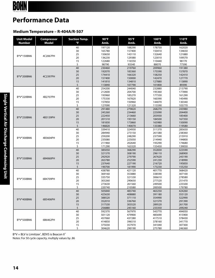
Medium Temperature – R-404A/R-507
Performance Data
Unit ModelNumber
CompressorModel
Suction Temp.°F
90°FAmb.
95°F Amb.
100°F Amb.
110°F Amb.
b*V*150bM6 4C2067PH
40302520155
19712016578015065013623012268098790
18829015740014311012938011655093540
17875015041013264012301011044088070
1620201346501218801095709817077590
b*V*200bM6 4C2397PH
40302520155
230460192070174410157400141810113840
219760183360166320150000134810107790
209960175590158250142470127880101800
19138015787014241012777011389089390
b*V*220bM6 4b2707PH
40302520155
254200212600193960175330157850127090
244040204700185270167820150960121320
232880195360177330160390144070115590
213790177890161290145490130340103770
b*V*250bM6 4b3139PH
40302520155
291480245260222450201510181830146820
279820234460213660193150173860140070
268270225090203930184500165980133380
243980204400185400167350150090119580
b*V*300bM6 4b3604PH
40302520155
339410284940259200235080211960171290
324930273150248290225050202640163320
311370261580237590214940193290155450
285650238360215910194800174680139050
b*V*330bM6 6b4060PH
40302520155
385050321570292920263780237640190700
368290308190279790252590227190181990
352830296110267620241230216720173230
323590268900243190218990195850155250
b*V*350bM6 6b4709PH
40302520155
438780369160335750303260273630220740
421120353880321530290650261560210580
401770338590306610277520249500200500
368420307100278580251470225500179780
b*V*400bM6 6b5406PH
40302520155
505840425630388520352010317530256880
483740408880371110336760303520245160
463250391180354990321570289520233350
424260355120322990291390261700209240
b*V*500bM6 6b6462PH
40302520155
592370501120457060414850375030304620
567970479900437280396510357970290190
543770485690417510378160341040275780
494050415900378430341770307300246360
b*V = bLV is Limitizer®, bDVS is beacon II™
notes: For 50 cycle capacity, multiply values by .86
15
Sing
le V
erti
cal A
ir D
isch
arge
Con
dens
ing
Uni
t
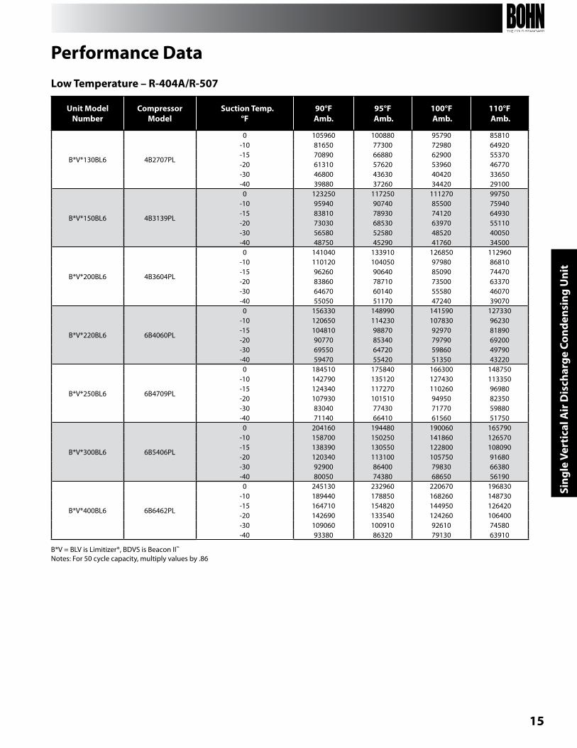
Low Temperature – R-404A/R-507
Unit ModelNumber
CompressorModel
Suction Temp.°F
90°FAmb.
95°F Amb.
100°F Amb.
110°F Amb.
b*V*130bL6 4b2707PL
0 105960 100880 95790 85810-10 81650 77300 72980 64920-15 70890 66880 62900 55370-20 61310 57620 53960 46770-30 46800 43630 40420 33650-40 39880 37260 34420 29100
b*V*150bL6 4b3139PL
0 123250 117250 111270 99750-10 95940 90740 85500 75940-15 83810 78930 74120 64930-20 73030 68530 63970 55110-30 56580 52580 48520 40050-40 48750 45290 41760 34500
b*V*200bL6 4b3604PL
0 141040 133910 126850 112960-10 110120 104050 97980 86810-15 96260 90640 85090 74470-20 83860 78710 73500 63370-30 64670 60140 55580 46070-40 55050 51170 47240 39070
b*V*220bL6 6b4060PL
0 156330 148990 141590 127330-10 120650 114230 107830 96230-15 104810 98870 92970 81890-20 90770 85340 79790 69200-30 69550 64720 59860 49790-40 59470 55420 51350 43220
b*V*250bL6 6b4709PL
0 184510 175840 166300 148750-10 142790 135120 127430 113350-15 124340 117270 110260 96980-20 107930 101510 94950 82350-30 83040 77430 71770 59880-40 71140 66410 61560 51750
b*V*300bL6 6b5406PL
0 204160 194480 190060 165790-10 158700 150250 141860 126570-15 138390 130550 122800 108090-20 120340 113100 105750 91680-30 92900 86400 79830 66380-40 80050 74380 68650 56190
b*V*400bL6 6b6462PL
0 245130 232960 220670 196830-10 189440 178850 168260 148730-15 164710 154820 144950 126420-20 142690 133540 124260 106400-30 109060 100910 92610 74580-40 93380 86320 79130 63910
Performance Data
b*V = bLV is Limitizer®, bDVS is beacon II™
notes: For 50 cycle capacity, multiply values by .86
16
Single Vertical Air D
ischarge Condensing Unit
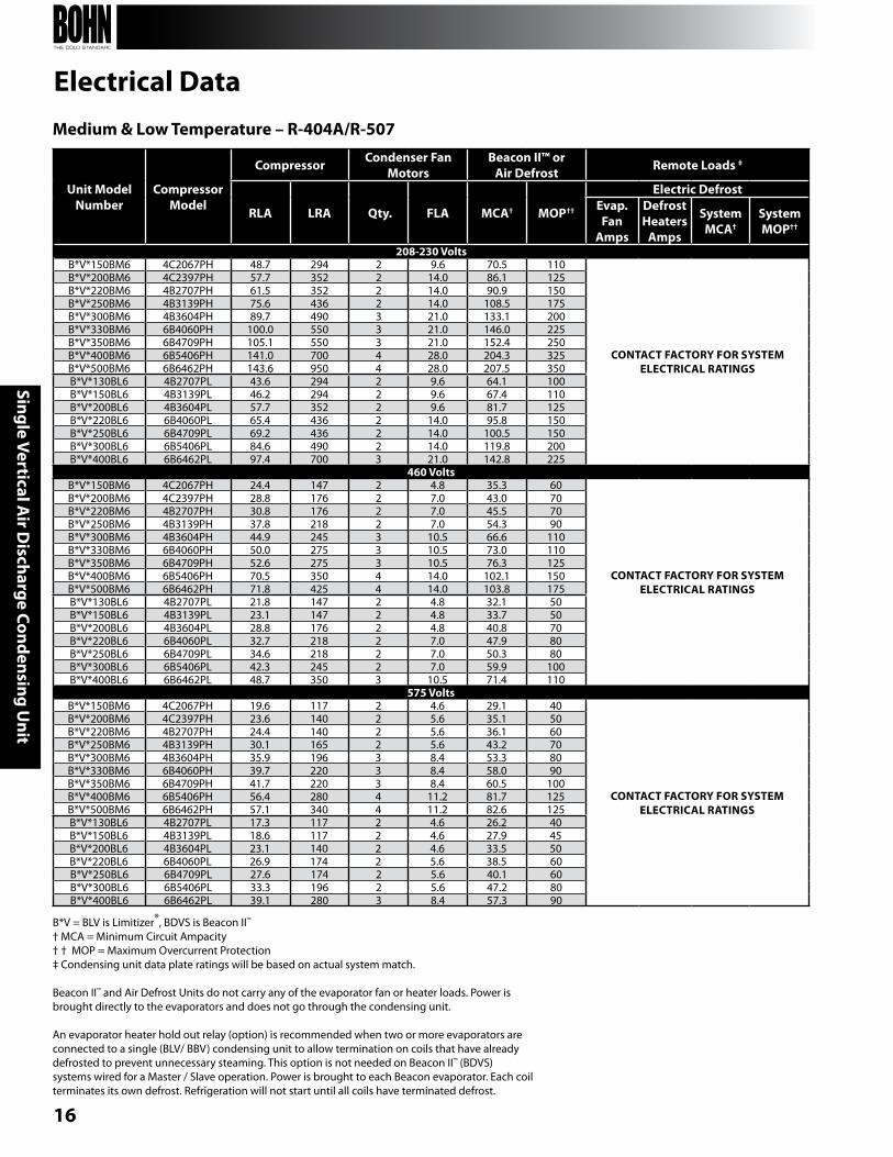
Medium & Low Temperature – R-404A/R-507
b*V = bLV is Limitizer®, bDVS is beacon II™
† MCA = Minimum Circuit Ampacity † † MOP = Maximum Overcurrent Protection‡ Condensing unit data plate ratings will be based on actual system match. beacon II™ and Air Defrost Units do not carry any of the evaporator fan or heater loads. Power is brought directly to the evaporators and does not go through the condensing unit. An evaporator heater hold out relay (option) is recommended when two or more evaporators are connected to a single (bLV/ bbV) condensing unit to allow termination on coils that have already defrosted to prevent unnecessary steaming. This option is not needed on beacon II™ (bDVS) systems wired for a Master / Slave operation. Power is brought to each beacon evaporator. Each coil terminates its own defrost. Refrigeration will not start until all coils have terminated defrost.
Electrical Data
Unit ModelNumber
Compressor Model
Compressor Condenser Fan Motors
Beacon II™ orAir Defrost Remote Loads ‡
RLA LRA Qty. FLA MCA† MOP††
Electric DefrostEvap. Fan
Amps
DefrostHeaters
Amps
System MCA†
System MOP††
208-230 Voltsb*V*150bM6 4C2067PH 48.7 294 2 9.6 70.5 110
CONTACT FACTORY FOR SYSTEM ELECTRICAL RATINgS
b*V*200bM6 4C2397PH 57.7 352 2 14.0 86.1 125b*V*220bM6 4b2707PH 61.5 352 2 14.0 90.9 150b*V*250bM6 4b3139PH 75.6 436 2 14.0 108.5 175b*V*300bM6 4b3604PH 89.7 490 3 21.0 133.1 200b*V*330bM6 6b4060PH 100.0 550 3 21.0 146.0 225b*V*350bM6 6b4709PH 105.1 550 3 21.0 152.4 250b*V*400bM6 6b5406PH 141.0 700 4 28.0 204.3 325b*V*500bM6 6b6462PH 143.6 950 4 28.0 207.5 350b*V*130bL6 4b2707PL 43.6 294 2 9.6 64.1 100b*V*150bL6 4b3139PL 46.2 294 2 9.6 67.4 110b*V*200bL6 4b3604PL 57.7 352 2 9.6 81.7 125b*V*220bL6 6b4060PL 65.4 436 2 14.0 95.8 150b*V*250bL6 6b4709PL 69.2 436 2 14.0 100.5 150b*V*300bL6 6b5406PL 84.6 490 2 14.0 119.8 200b*V*400bL6 6b6462PL 97.4 700 3 21.0 142.8 225
460 Voltsb*V*150bM6 4C2067PH 24.4 147 2 4.8 35.3 60
CONTACT FACTORY FOR SYSTEM ELECTRICAL RATINgS
b*V*200bM6 4C2397PH 28.8 176 2 7.0 43.0 70b*V*220bM6 4b2707PH 30.8 176 2 7.0 45.5 70b*V*250bM6 4b3139PH 37.8 218 2 7.0 54.3 90b*V*300bM6 4b3604PH 44.9 245 3 10.5 66.6 110b*V*330bM6 6b4060PH 50.0 275 3 10.5 73.0 110b*V*350bM6 6b4709PH 52.6 275 3 10.5 76.3 125b*V*400bM6 6b5406PH 70.5 350 4 14.0 102.1 150b*V*500bM6 6b6462PH 71.8 425 4 14.0 103.8 175b*V*130bL6 4b2707PL 21.8 147 2 4.8 32.1 50b*V*150bL6 4b3139PL 23.1 147 2 4.8 33.7 50b*V*200bL6 4b3604PL 28.8 176 2 4.8 40.8 70b*V*220bL6 6b4060PL 32.7 218 2 7.0 47.9 80b*V*250bL6 6b4709PL 34.6 218 2 7.0 50.3 80b*V*300bL6 6b5406PL 42.3 245 2 7.0 59.9 100b*V*400bL6 6b6462PL 48.7 350 3 10.5 71.4 110
575 Voltsb*V*150bM6 4C2067PH 19.6 117 2 4.6 29.1 40
CONTACT FACTORY FOR SYSTEM ELECTRICAL RATINgS
b*V*200bM6 4C2397PH 23.6 140 2 5.6 35.1 50b*V*220bM6 4b2707PH 24.4 140 2 5.6 36.1 60b*V*250bM6 4b3139PH 30.1 165 2 5.6 43.2 70b*V*300bM6 4b3604PH 35.9 196 3 8.4 53.3 80b*V*330bM6 6b4060PH 39.7 220 3 8.4 58.0 90b*V*350bM6 6b4709PH 41.7 220 3 8.4 60.5 100b*V*400bM6 6b5406PH 56.4 280 4 11.2 81.7 125b*V*500bM6 6b6462PH 57.1 340 4 11.2 82.6 125b*V*130bL6 4b2707PL 17.3 117 2 4.6 26.2 40b*V*150bL6 4b3139PL 18.6 117 2 4.6 27.9 45b*V*200bL6 4b3604PL 23.1 140 2 4.6 33.5 50b*V*220bL6 6b4060PL 26.9 174 2 5.6 38.5 60b*V*250bL6 6b4709PL 27.6 174 2 5.6 40.1 60b*V*300bL6 6b5406PL 33.3 196 2 5.6 47.2 80b*V*400bL6 6b6462PL 39.1 280 3 8.4 57.3 90
17
Sing
le V
erti
cal A
ir D
isch
arge
Con
dens
ing
Uni
t
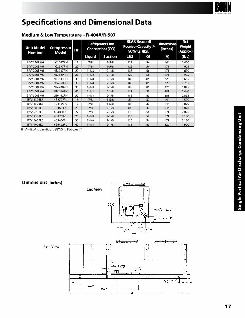
End View
Side View
Medium & Low Temperature – R-404A/R-507
Dimensions (Inches)
Specifications and Dimensional Data
b*V = bLV is Limitizer®, bDVS is beacon II™
Unit ModelNumber
CompressorModel HP
Refrigerant Line Connections (OD)
BLV & Beacon IIReceiver Capacity @
90% full (lbs.)
Dimensions(Inches)
NetWeight
(Approx)Liquid Suction LBS Kg (A) (lbs)
b*V*150bM6 4C2067PH 15 7/8 1-5/8 123 56 144 1,400b*V*200bM6 4C2397PH 20 7/8 1-5/8 123 56 171 1,625b*V*220bM6 4b2707PH 22 1-1/8 2-1/8 123 56 171 1,690b*V*250bM6 4b3139PH 25 1-1/8 2-1/8 123 56 171 1,935b*V*300bM6 4b3604PH 30 1-1/8 2-1/8 188 85 226 1,615b*V*330bM6 6b4060PH 33 1-1/8 2-1/8 188 85 226 1,785b*V*350bM6 6b4709PH 35 1-1/8 2-1/8 188 85 226 1,885b*V*400bM6 6b5406PH 40 1-1/8 2-1/8 188 85 281 2,440b*V*500bM6 6b6462PH 50 1-1/8 2-1/8 188 85 281 2,835b*V*130bL6 4b2707PL 13 7/8 1-5/8 81 37 144 1,590b*V*150bL6 4b3139PL 15 7/8 1-5/8 81 37 144 1,800b*V*200bL6 4b3604PL 20 7/8 2-1/8 81 37 144 1,870b*V*220bL6 6b4060PL 22 7/8 2-1/8 123 56 171 2,075b*V*250bL6 6b4709PL 25 1-1/8 2-1/8 123 56 171 2,170b*V*300bL6 6b5406PL 30 1-1/8 2-1/8 123 56 171 2,180b*V*400bL6 6b6462PL 40 1-1/8 2-1/8 188 85 226 1,920
18
Dual Vertical A
ir Discharge Condensing U
nit
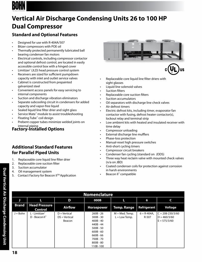
Vertical Air Discharge Condensing Units 26 to 100 HPDual Compressor
Additional Standard Features for Parallel Piped Units1. Replaceable core liquid line filter drier2. Replaceable core suction filter3. Suction accumulator4. Oil management system5. Contact Factory for beacon IITM Application
Standard and Optional Features
• Designed for use with R-404A/507• bitzer compressors with POE oil• Thermally protected permanently lubricated ball
bearing condenser fan motors• Electrical controls, including compressor contactor
and optional defrost control, are located in easily accessible control box with a hinged cover
• Limitizer® (JLD) head pressure control system• Receivers are sized for sufficient pumpdown
capacity with inlet and outlet service valves• Cabinet is constructed from prepainted
galvanized steel• Convenient access panels for easy servicing to
internal components• Suction and discharge vibration eliminators• Separate subcooling circuit in condensers for added
capacity and vapor-free liquid• Sealed liquid line filter drier and sight glass• Service Mate™ module to assist troubleshooting• Floating Tube™ coil design• Prebent copper tubes minimize welded joints on
internal pipingFactory-Installed Options
• Replaceable core liquid line filter driers with sight glasses
• Liquid line solenoid valves• Suction filters• Replaceable core suction filters• Suction accumulators• Oil separators with discharge line check valves• Air defrost timers• Electric defrost kits, including timer, evaporator fan
contactor with fusing, defrost heater contactor(s), lockout relay and terminal strip
• Low ambient kits with heated and insulated receiver with time delay
• Compressor unloading• External discharge line mufflers• Phase-loss protection• Manual-reset high pressure switches• Anti-short cycling timers• Compressor circuit breakers• Condenser fan cycling (standard on JDDS)• Three way heat reclaim valve with mounted check valves
(n/a on JbD)• Coated condenser coils for protection against corrosion
in harsh environments• beacon II™ compatible
NomenclatureJ L D 000B L 6 C
Brand Head Pressure Control Airflow Horsepower Temp. Range Refrigerant Voltage
J = bohn L - Limitizer®
D - beacon II™D = VerticalDS = Vertical beacon
260b - 26300b - 30400b - 40440b - 44500b - 50600b - 60660b - 66700b - 70800b - 80110b -100
M = Med. Temp.L = Low Temp.
6 = R-404A, R-507
C = 208-230/3/60D = 460/3/60E = 575/3/60
19
Dua
l Ver
tica
l Air
Dis
char
ge C
onde
nsin
g U
nit
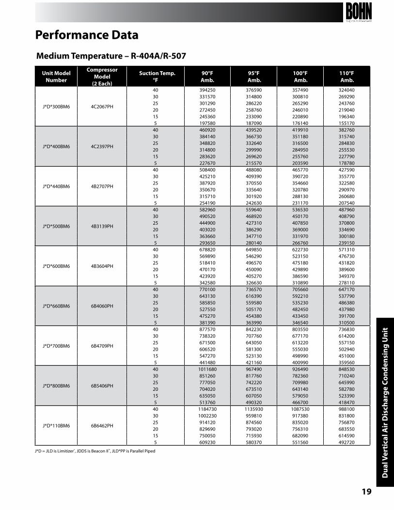
Performance Data
Unit ModelNumber
Compressor Model
(2 Each)
Suction Temp.°F
90°FAmb.
95°F Amb.
100°F Amb.
110°F Amb.
J*D*300bM6 4C2067PH
40 394250 376590 357490 32404030 331570 314800 300810 26929025 301290 286220 265290 24376020 272450 258760 246010 21904015 245360 233090 220890 1963405 197580 187090 176140 155170
J*D*400bM6 4C2397PH
40 460920 439520 419910 38276030 384140 366730 351180 31574025 348820 332640 316500 28483020 314800 299990 284950 25553015 283620 269620 255760 2277905 227670 215570 203590 178780
J*D*440bM6 4b2707PH
40 508400 488080 465770 42759030 425210 409390 390720 35577025 387920 370550 354660 32258020 350670 335640 320780 29097015 315710 301920 288130 2606805 254190 242630 231170 207540
J*D*500bM6 4b3139PH
40 582960 559640 536530 48796030 490520 468920 450170 40879025 444900 427310 407850 37080020 403020 386290 369000 33469015 363660 347710 331970 3001805 293650 280140 266760 239150
J*D*600bM6 4b3604PH
40 678820 649850 622730 57131030 569890 546290 523150 47673025 518410 496570 475180 43182020 470170 450090 429890 38960015 423920 405270 386590 3493705 342580 326630 310890 278110
J*D*660bM6 6b4060PH
40 770100 736570 705660 64717030 643130 616390 592210 53779025 585850 559580 535230 48638020 527550 505170 482450 43798015 475270 454380 433450 3917005 381390 363990 346540 310500
J*D*700bM6 6b4709PH
40 877570 842230 803550 73683030 738320 707760 677170 61420025 671500 643050 613220 55715020 606520 581300 555030 50294015 547270 523130 498990 4510005 441480 421160 400990 359560
J*D*800bM6 6b5406PH
40 1011680 967490 926490 84853030 851260 817760 782360 71024025 777050 742220 709980 64599020 704020 673510 643140 58278015 635050 607050 579050 5233905 513760 490320 466700 418470
J*D*110bM6 6b6462PH
40 1184730 1135930 1087530 98810030 1002230 959810 917380 83180025 914120 874560 835020 75687020 829690 793020 756310 68355015 750050 715930 682090 6145905 609230 580370 551560 492720
Medium Temperature – R-404A/R-507
J*D = JLD is Limitizer®, JDDS is beacon II™, JLD*PP is Parallel Piped
20
Dual Vertical A
ir Discharge Condensing U
nit
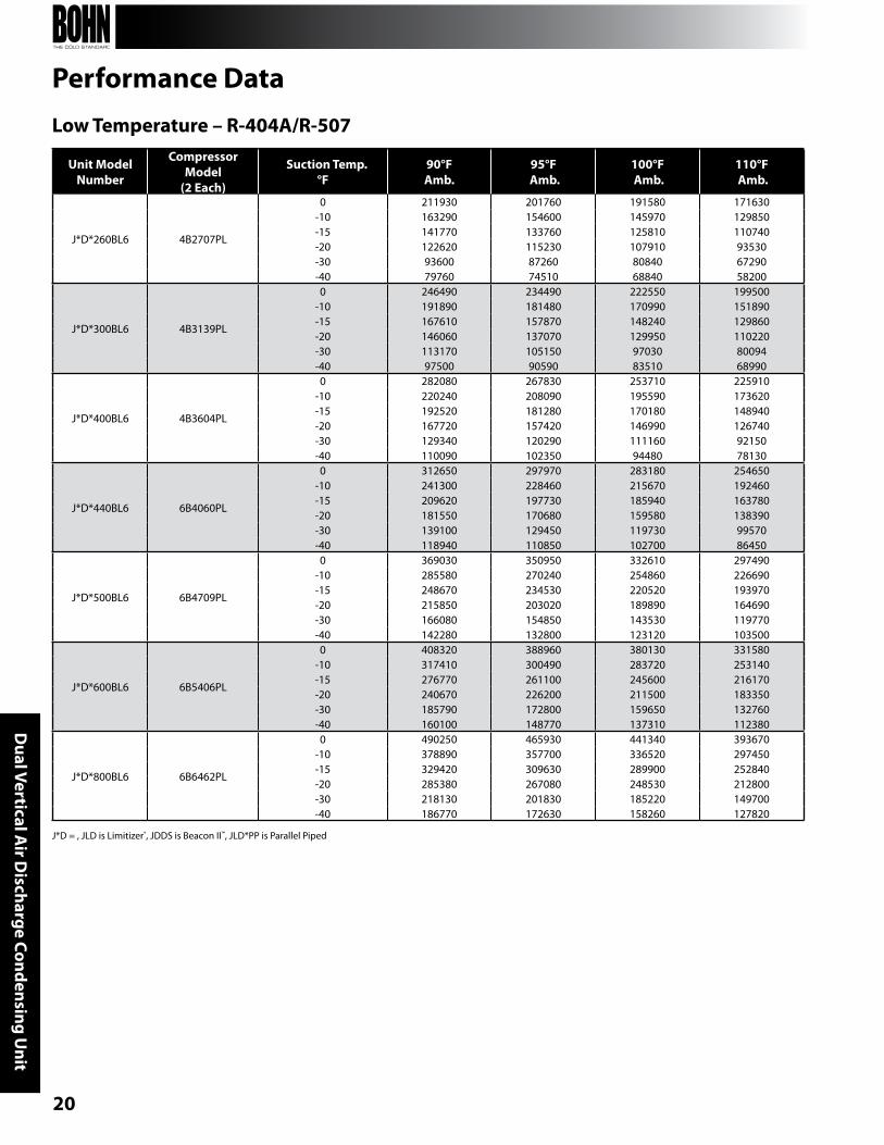
Unit ModelNumber
Compressor Model
(2 Each)
Suction Temp.°F
90°FAmb.
95°F Amb.
100°F Amb.
110°F Amb.
J*D*260bL6 4b2707PL
0 211930 201760 191580 171630-10 163290 154600 145970 129850-15 141770 133760 125810 110740-20 122620 115230 107910 93530-30 93600 87260 80840 67290-40 79760 74510 68840 58200
J*D*300bL6 4b3139PL
0 246490 234490 222550 199500-10 191890 181480 170990 151890-15 167610 157870 148240 129860-20 146060 137070 129950 110220-30 113170 105150 97030 80094-40 97500 90590 83510 68990
J*D*400bL6 4b3604PL
0 282080 267830 253710 225910-10 220240 208090 195590 173620-15 192520 181280 170180 148940-20 167720 157420 146990 126740-30 129340 120290 111160 92150-40 110090 102350 94480 78130
J*D*440bL6 6b4060PL
0 312650 297970 283180 254650-10 241300 228460 215670 192460-15 209620 197730 185940 163780-20 181550 170680 159580 138390-30 139100 129450 119730 99570-40 118940 110850 102700 86450
J*D*500bL6 6b4709PL
0 369030 350950 332610 297490-10 285580 270240 254860 226690-15 248670 234530 220520 193970-20 215850 203020 189890 164690-30 166080 154850 143530 119770-40 142280 132800 123120 103500
J*D*600bL6 6b5406PL
0 408320 388960 380130 331580-10 317410 300490 283720 253140-15 276770 261100 245600 216170-20 240670 226200 211500 183350-30 185790 172800 159650 132760-40 160100 148770 137310 112380
J*D*800bL6 6b6462PL
0 490250 465930 441340 393670-10 378890 357700 336520 297450-15 329420 309630 289900 252840-20 285380 267080 248530 212800-30 218130 201830 185220 149700-40 186770 172630 158260 127820
Low Temperature – R-404A/R-507
Performance Data
J*D = , JLD is Limitizer®, JDDS is beacon II™, JLD*PP is Parallel Piped

21
Dua
l Ver
tica
l Air
Dis
char
ge C
onde
nsin
g U
nit
J*D = JLD is Limitizer®, JDDS is beacon II™, JLD*PP is Parallel Piped† MCA = Minimum Circuit Ampacity†† MOP = Maximum Overcurrent Protection‡ Condensing unit data plate ratings will be based on actual system match.
Electrical DataMedium & Low Temperature – R-404A/507
Unit ModelNumber
Compressor Model
(2 Each)
Compressor Condenser Fan Motors
Beacon II™ or Air Defrost Remote Loads ‡
RLA LRA Qty. FLA MCA† MOP††
Electric DefrostEvap.Fan
Amps
DefrostHeaters
Amps
SystemMCA†
SystemMOP††
208-230 VoltsJ*D*300bM6 4C2067PH 48.7 294 4 19.2 128.8 175
CONTACT FACTORY FOR SYSTEM ELECTRICAL RATINgS
J*D*400bM6 4C2397PH 57.7 352 4 28.0 157.8 200J*D*440bM6 4b2707PH 61.5 352 4 28.0 166.4 225J*D*500bM6 4b3139PH 75.6 436 4 28.0 198.1 250J*D*600bM6 4b3604PH 89.7 490 6 42.0 243.8 325J*D*660bM6 6b4060PH 100.0 550 6 42.0 267.0 350J*D*700bM6 6b4709PH 105.1 550 6 42.0 278.5 350J*D*800bM6 6b5406PH 141.0 700 8 56.0 373.3 500J*D*110bM6 6b6462PH 143.6 950 8 56.0 379.1 500J*D*260bL6 4b2707PL 43.6 294 4 19.2 117.3 150J*D*300bL6 4b3139PL 46.2 294 4 19.2 123.2 150J*D*400bL6 4b3604PL 57.7 352 4 19.2 149.0 200J*D*440bL6 6b4060PL 65.4 436 4 28.0 175.2 225J*D*500bL6 6b4709PL 69.2 436 4 28.0 183.7 250J*D*600bL6 6b5406PL 84.6 490 4 28.0 218.4 300J*D*800bL6 6b6462PL 97.4 700 6 42.0 261.2 350
460 VoltsJ*D*300bM6 4C2067PH 24.4 147 4 9.6 64.5 80
CONTACT FACTORY FOR SYSTEM ELECTRICAL RATINgS
J*D*400bM6 4C2397PH 28.8 176 4 14.0 78.8 100J*D*440bM6 4b2707PH 30.8 176 4 14.0 83.3 110J*D*500bM6 4b3139PH 37.8 218 4 14.0 99.1 125J*D*600bM6 4b3604PH 44.9 245 6 21.0 122.0 150J*D*660bM6 6b4060PH 50.0 275 6 21.0 133.5 175J*D*700bM6 6b4709PH 52.6 275 6 21.0 139.4 175J*D*800bM6 6b5406PH 70.5 350 8 28.0 186.6 250J*D*110bM6 6b6462PH 71.8 425 8 28.0 189.6 250J*D*260bL6 4b2707PL 21.8 147 4 9.6 58.7 80J*D*300bL6 4b3139PL 23.1 147 4 9.6 61.6 80J*D*400bL6 4b3604PL 28.8 176 4 9.6 74.4 100J*D*440bL6 6b4060PL 32.7 218 4 14.0 87.6 110J*D*500bL6 6b4709PL 34.6 218 4 14.0 91.9 125J*D*600bL6 6b5406PL 42.3 245 4 14.0 109.2 150J*D*800bL6 6b6462PL 48.7 350 6 21.0 130.6 175
575 VoltsJ*D*300bM6 4C2067PH 19.6 117 4 9.2 53.3 70
CONTACT FACTORY FOR SYSTEM ELECTRICAL RATINgS
J*D*400bM6 4C2397PH 23.6 140 4 11.2 64.3 80J*D*440bM6 4b2707PH 24.4 140 4 11.2 66.1 90J*D*500bM6 4b3139PH 30.1 165 4 11.2 78.9 100J*D*600bM6 4b3604PH 35.9 196 6 16.8 97.6 125J*D*660bM6 6b4060PH 39.7 220 6 16.8 106.1 125J*D*700bM6 6b4709PH 41.7 220 6 16.8 110.6 150J*D*800bM6 6b5406PH 56.4 280 8 22.4 149.3 200J*D*110bM6 6b6462PH 57.1 340 8 22.4 150.9 200J*D*260bL6 4b2707PL 17.3 117 4 9.2 48.1 60J*D*300bL6 4b3139PL 18.6 117 4 9.2 51.1 70J*D*400bL6 4b3604PL 23.1 140 4 9.2 61.2 80J*D*440bL6 6b4060PL 26.3 174 4 11.2 70.4 90J*D*500bL6 6b4709PL 27.6 174 4 11.2 73.3 100J*D*600bL6 6b5406PL 33.3 196 4 11.2 86.1 110J*D*800bL6 6b6462PL 39.1 280 6 16.8 104.8 125
22
Dual Vertical A
ir Discharge Condensing U
nit
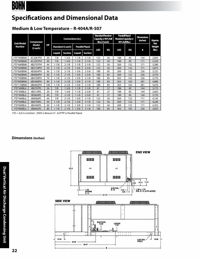
J*D = JLD is Limitizer®, JDDS is beacon II™, JLD*PP is Parallel Piped
Specifications and Dimensional Data
Unit Model Number
Compressor Model
(2 each)HP
Connections (in.)Standard ReceiverCapacity @ 90% full
(lbs.) (2 each)
Paralell Piped Receiver Capacity @
90% full (lbs.)
Dimensions (inches) Approx.
Net Weight
(lbs.)Standard (2 each) Parallel Piped
LBS Kg LBS Kg ALiquid Suction Liquid Suction
J*D*300bM6 4C2067PH 30 7/8 1-5/8 1-1/8 2-1/8 123 56 188 85 144 2,805J*D*400bM6 4C2397PH 40 7/8 1-5/8 1-1/8 2-1/8 123 56 188 85 171 3,250J*D*440bM6 4b2707PH 44 1-1/8 2-1/8 1-1/8 2-1/8 123 56 269 122 171 3,380J*D*500bM6 4b3139PH 50 1-1/8 2-1/8 1-3/8 2-5/8 123 56 269 122 171 3,875J*D*600bM6 4b3604PH 60 1-1/8 2-1/8 1-3/8 2-5/8 188 85 269 122 226 3,225J*D*660bM6 6b4060PH 66 1-1/8 2-1/8 1-3/8 2-5/8 188 85 269 122 226 3,570J*D*700bM6 6b4709PH 70 1-1/8 2-1/8 1-5/8 3-1/8 188 85 363 165 226 3,770J*D*800bM6 6b5406PH 80 1-1/8 2-1/8 1-5/8 3-1/8 188 85 363 165 281 4,880J*D*110bM6 6b6462PH 100 1-1/8 2-1/8 1-5/8 3-1/8 188 85 363 165 281 5,670J*D*260bL6 4b2707PL 26 7/8 1-5/8 1-1/8 2-1/8 81 37 188 85 144 3,175J*D*300bL6 4b3139PL 30 7/8 1-5/8 1-1/8 2-5/8 81 37 188 85 144 3,605J*D*400bL6 4b3604PL 40 7/8 2-1/8 1-1/8 2-5/8 81 37 188 85 144 3,735J*D*440bL6 6b4060PL 44 7/8 2-1/8 1-3/8 3-1/8 123 56 269 122 171 4,145J*D*500bL6 6b4709PL 50 1-1/8 2-1/8 1-3/8 3-1/8 123 56 269 122 171 4,240J*D*600bL6 6b5406PL 60 1-1/8 2-1/8 1-3/8 3-1/8 123 56 269 122 171 4,355J*D*800bL6 6b6462PL 80 1-1/8 2-1/8 1-3/8 3-1/8 188 85 363 165 226 3,835
Dimensions (Inches)
Medium & Low Temperature – R-404A/R-507
23
A Brand of Heatcraft Refrigeration Products LLC2175 West Park Place Blvd. • Stone Mountain, gA • 30087(800) 537-7775 • FAX (770) 465-5990
www.heatcraftrpd.com
For more information on bohn refrigeration products, contact your sales representative or visit us at www.heatcrafrpd.com.
Since product improvement is a continuing effort, we reserve the right to make changes in specifications without notice.