Jascko Corp. – Heating Ventilation Air Conditioning Units ...

Guide to installation
The specifications, designs and information in this brochure are subject to change without notice.
November. 2008, Printed in Japan
AIR CONDITIONING SYSTEMS
For Internal Training

Example
– 1 –
Poor performance due to indoor unit capacity
Possible Problems
Insufficient cooling when increasing the number of operating indoor units.Insufficient heating when increasing the number of operating indoor units.
Cautions and CountermeasuresIndoor unit performance will fall below the rating level if the total capacity of the indoor units in operation in a same refrigerant system exceeds the outdoor unit capacity.Refer to the Data Book for information regarding indoor unit performance changes related to the total capacity of the connected indoor units.The maximum capacity of indoor unit connection is 150% for the R2 Series.
It is recommended to design the system so that the capacity of indoor units operating simultaneously does not exceed the outdoor unit capacity.A 130% connection is not recommended in high-loaded areas (room direction/capacity). Where the load is high (hot regions / crowded areas). Install the units considering the load balance.
Indoor unit capacity 65kW (130% connection)(Peak load for heat recovery operation) 60kW
Comfortable evenon midsummer days
Low cooling load
High cooling load
Design for max. indoor unit connection
capacity (100%)
Design for max. indoor unit connection
capacity (130%)
Low cooling load
High cooling load
Outdoor unit 50kWpeak load conditionsperformance
Outdoor unit 50kWpeak load conditionsperformance
Indoor unit capacity 65kW (130% connection)(Peak load for heat recovery operation) 60kW
Too hot on midsummer days
Indoor unit capacity 50kW (100% connection)(Peak load for heat recovery operation) 50kW
Ideal conditions
1R
efri
gera
nt P
ipin
g W
ork
Dra
in P
ipin
g W
ork
CONTENTS
1. Poor performance due to indoor unit capacity 1
2. Backup Air Conditioner 2
3. Room Temperature Rise in Rooms with Small Heating Loads 3
4. Refrigerant Flow Noise when the Heater Thermostat is Not ON
(Thermo OFF, FAN, OFF) 4
5. Processing the Drain From Outdoor Units 5
6. Installation of BC controller 6
7. BC Controller Installation Position and Access door of Ceiling
Concealed Type Indoor Unit 7
8. Loud Air Outlet Sound at Ducted Indoor Unit 8
9. Condensation at Air Outlet 9
10. Large Difference Between Temperature Detected
by Remote Controller Sensor and Room Temperature 9
11. Installation space 10
12. Outdoor unit installation locations 10
13. Influence of strong wind to outdoor unit 11
14. Installation of outdoor unit in a region likely to be influenced by sea breeze 12
15. Troubles about indoor unit due to environmental substances 13~16
16. Problems Related to the Indoor Unit's Ambient Temperature and Humidity Conditions 17
17. Refrigerant pipe branching method at outdoor unit 18
18. Additional Refrigerant Pipe Branching after The Branch Header 19
19. Refrigerant Piping and Transmission Line Mismatch 19
20. Foreign Substance In The Refrigerant Circuit 20
21. Condensation Caused by Insufficient Insulation Thickness at Refrigerant Piping 21
22. Incorrect Additional Refrigerant Charging 22
23. Gas Leakage Due to Improper Flare Work 23
24. Air mixed in refrigerant piping or air conditioning unit 24
25. Combining of horizontal drain piping 25
26. Troubles about horizontal drain piping 26
27. Combining of horizontal drain piping 27
28. Entry of odor/corrosive gas from drain piping 28
29. Water Leakage From Drain Pipe Connection Area 29
30. Selecting a Breaker For Ground fault 30
31. Transmission Errors Related to the Transmission Line Type and Length 31
32. Malfunctions Due To Using the Same Power Supply
and Ground Devices as the Outdoor Unit 31
33. Incorrect ME Remote Controller Wiring 32
34. Poor Contact at Transmission Line Connection 32
35. Address Setting Error 33
36. Mismatch When Changing the Address Setting 34
37. Incorrect MELANS System Configuration 35
38. Valve Operation After Vacuumizing the Onsite Piping 36
39. Compressor Failure Immediately After Power ON 37
40. Using AUTO Cooling/Heating Mode 37
Inst
alla
tio
n W
ork
Wir
ing
Wor
kTe
st r
unre
late
d
Inst
alla
tio
n W
ork

Example 3
– 3 –
Light air
Heating
Room Temperature Rise in Rooms with SmallHeating Loads
Thermostat ON
Heating
Thermostat ON
Thermostat OFF Thermostat OFF
Room temperatureRoom temperatureMain unitthermostat
Remote controller thermostat
Room temperature rise by light warm airblowing when thermostat is OFF.
Remote controller's built-in thermostat detects roomtemperature and Fan setting OFF when thermostat is OFF.
Fan stop
Possible Problems
Overheating
Cautions and CountermeasuresWhen a small room (small heating load) is connected to the same refrigerant system as a large room, the small room's temperature may rise even though the thermostat is OFF. When thermostat is OFF, light air blows at the indoor unit to detect room temperature and refrigerant is slightly flowing to prevent accumulating inside the indoor unit. In cases where a room is small (small heating load), the light air blowing which occurs while the thermostat is OFF may rise the room temperature. (This does not apply to the R2 Series.)
In cases where a room temperature rises (as described above), switch the room temperature sensor to built-in sensor(set indoor unit dip switch to 1-1 ON), and specify a setting which stops the air from blowing while the thermostat is OFF (set the indoor unit dip switch1-7 and 1-8 ON.)
Example 2 Backup Air Conditioner
– 2 –
Backup system
Air conditioner stops
Life-threatening consequencesif air conditioner stops.
Wah-wah
No need to worry.
Fall asleep
Possible Problems
Room temperature changes during an air conditioner failure could cause health problems and illness.An air conditioner failure could cause secondary damage such as the loss of important data, and the disabling of vital equipment, etc.
Cautions and CountermeasuresBe sure to install a backup unit for indoor units where secondary damage could result from air conditioner shutdown due to repairs, or from reduced performance due or filter clogging, etc..Be sure to use a different refrigerant system for the backup indoor unit.
Inst
alla
tio
n W
ork
Inst
alla
tio
n W
ork

Example 4
– 4 –
Refrigerant Flow Noise when the Heater Thermostatis Not ON (Thermo OFF, FAN, OFF)
Possible Problems
Refrigerant flowing noise.
Cautions and CountermeasuresA refrigerant flow noise (hissing sound, running water sound, or gurgling sound, etc.) may be audible when the indoor unit is in a status other than Thermo-ON. This occurs because the expansion valve remains slightly open when the indoor unit is not Thermo-ON in order to prevent refrigerant accumulation inside the indoor unit. This is particularly noticeable at operation start and defrost recoveries, because the valve opening is relatively larger at those times, resulting in a louder refrigerant noise.Noise prevention measures such as selecting ceiling-concealed type units, etc., for environments where silence is required (hotels, hospital rooms, bedrooms, etc.). Consult with our sales representative for details.An optional externally mounted LEV box (PAC-SG95LE-E) is available for wall-mounted type model (PKFY-P VBM-E model only).
HissssHissss
Optional externallymounted LEV box
Example 5
– 5 –
Processing the Drain From Outdoor Units
Drain pipe
Drain gutterDrain gutter
drain pan
Possible Problems
Drain drippingAlgae formationDrain pan freezing (in cold regions)
Cautions and CountermeasuresCondensation forms on a surface of a low-pressure part of a outdoor unit's refrigerant circuit and drains out through a multiple holes in a unit base. A method for handling this drain from a outdoor unit's bottom face should therefore be considered.Users are requested to consider using a drain pan with drainage piping, or have drainage gutters installed locally.Users in regions where the outside temperature is below zero should install a drain pan heater (procured locally).
Inst
alla
tio
n W
ork
Inst
alla
tio
n W
ork

Example 7
– 7 –
BC Controller Installation Position and Accessdoor of Ceiling Concealed Type Indoor Unit
Indoorunit
Indoorunit
Indoorunit
Indoorunit
Common-space Common-space
Indoorunit
Indoorunit
Indoorunit
Indoorunit
BCcontroller
BCcontroller
access door
Possible Problems
Complaints on operation noise.Maintenance trouble.
Cautions and CountermeasuresBC controllers for heat recovery outdoor units should be installed in shared areas such as the ceiling of corridors, etc., where the effects of noise are minimal. In such systems, internal solenoid and expansion valve operation noise may occur unrelated to the indoor unit operation. (In hotels, etc., where silence is required, BC controller is recommended to be installed 5m or more away from the indoor unit.)Be sure to install an Access door at the prescribed location for BC controller maintenance purposes.Always install an Access door for ceiling concealed type units.
Tenant A Tenant B Tenant A Tenant B
Example
– 6 –
Installation of BC controller
Cautions and CountermeasuresBC controllers are equipped with solenoid valves to change the refrigerant flow path and to bypass refrigerant. Depending on the operation conditions, fluid refrigerant will instantaneously evaporate to a gas refrigerant when solenoid valve operation occurs, resulting in a "pshuuu" sound.Install the unit in a location where the noise from the unit will not be a problem. (Install indoor unit and BC controller at least 5m away from each other when installed in a space with low background noise, e.g., hotel rooms).
Possible Problems
Noise produced by BC controllers can be disturbing.
6
Inst
alla
tio
n W
ork
Inst
alla
tio
n W
ork

Condensationcountermeasure
Insulating sheet applied
Example
– 9 –
Condensation at Air Outlet Large Difference Between Temperature Detectedby Remote Controller Sensor and Room Temperature9
Example
10
Temperature sensor
Roomtemperature 22oC<71.6oF>
Outdoortemperature -1oC<30.2oF>
Room temperature 22oC<71.6oF>
Possible Problems
Condensation at air outlet.Mold at air outlet.
A low air flow rate and a low-temperature air flow of an indoor unit could cause condensation on the air outlet equipment installed onsite. To avoid this, adjust the static pressure to operate at a standard air frow rate level equipment.Some air outlet equipment may allow outside air and humidity to enter around the air outlet area, causing condensation. Either install the air outlet equipment in a position which prevents this, or use an anti-condensation type fixture.
Cautions and Countermeasures
Possible Problems
The room being too cold or too warm.The room does not cool down or warm up.
Attention should be given to the following when indoor unit control is based on the temperature detected by the remote controller sensor.
Is the wall surface temperature significantly different from the room temperature?Is the air from the indoor unit blowing directly on the remote controller?Is the remote controller exposed to direct sunlight?Is the remote controller covered by a curtain, etc.?
Cautions and Countermeasures
Air outlet
Condensation
Condensationcountermeasure
Insulating sheet applied
Roomtemperature 18oC<64.4oF>
Outdoortemperature -1oC<30.2oF>
Temperature sensor
Roomtemperature 28oC<82.4oF>
Example
– 8 –
Loud Air Outlet Sound at Ducted Indoor Unit 8
Possible Problems
If a duct resistance (pressure loss) is smaller than the air-conditioner's external static pressure increases the air flow rate, resulting in a loud sound.
A loud sound occurs if no silencing measures are taken inside the duct, or if the wrong air outlet is selected.
Cautions and CountermeasuresConsider both the overall air resistance (pressure loss) of the onsite duct system (duct + air outlet + air inlet + …) and the external static pressure of the air-conditioner which is connected to that duct system to ensure the balance between the two.To prevent vibration transmission with steel plate type duct, connect to the duct system by way of a canvass duct.A unit inspection port is required, and it may also be necessary to install another inspection port for duct air flow rate adjusting damper operation. Installing a damper will increase the external static pressure, and this must be added to the onsite duct resistance.
Inaccurate external static pressure
Insufficient ductpressure loss
Appropriate ductpressure loss
Correct external static pressure
*Use only rust-resistant, nonflammable duct components, and give adequate consideration to the insulation and noise control when designing and installing the system.
Inst
alla
tio
n W
ork
Inst
alla
tio
n W
ork
Example
– 10 –
Installation space Outdoor unit installationlocations11
Example
12
A
A
wall
wall
Short cycle!!
Waste heatWaste heat
A B
B
wall
Possible Problems
Short cycleLow cooling capacityHigh pressure
In order to prevent short operating cycles, do not install the unit near a wall which is higher than the unit. For specific distances and installation details, refer to the Installation Manual.
Cautions and Countermeasures
Possible Problems
Noise produced by outdoor units can be disturbing.
Outdoor units are equipped with solenoid valves for heat exchange switching and for bypassing refrigerant. Depending on the operation conditions, fluid refrigerant will instantaneously evaporate to a gas refrigerant when solenoid valve operation occurs, resulting in a "pshuuu" sound.
Choose the installation site with care in order to avoid noise disturbance problems.
Cautions and Countermeasures
Example
– 11 –
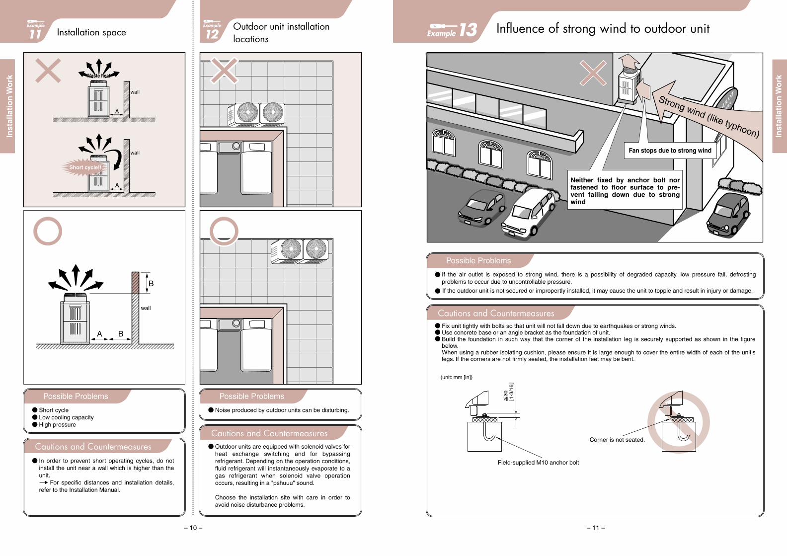
Influence of strong wind to outdoor unit
Cautions and Countermeasures
Possible Problems
Strong wind (like typhoon)
Neither fixed by anchor bolt nor fastened to floor surface to pre-vent falling down due to strong wind
If the air outlet is exposed to strong wind, there is a possibility of degraded capacity, low pressure fall, defrosting problems to occur due to uncontrollable pressure.
If the outdoor unit is not secured or impropertly installed, it may cause the unit to topple and result in injury or damage.
Fix unit tightly with bolts so that unit will not fall down due to earthquakes or strong winds.Use concrete base or an angle bracket as the foundation of unit.Build the foundation in such way that the corner of the installation leg is securely supported as shown in the figure below.When using a rubber isolating cushion, please ensure it is large enough to cover the entire width of each of the unit's legs. If the corners are not firmly seated, the installation feet may be bent.
Fan stops due to strong wind
(unit: mm [in])
Field-supplied M10 anchor bolt
Corner is not seated.
13
Inst
alla
tio
n W
ork
Inst
alla
tio
n W
ork

The indoor unit of an air conditioner may be in a trouble caused by damaged plastic parts, or clogged heat exchangers due to the environmental load substances (soot of machine oil, organic solvent contained in paint, edible oil used by kitchens, roast meat and baked food shops, vinegar used by sushi bar, powder generated by tea manufacturing factory, etc.) existing in your installation environment. Please employ preventive maintenance (life prolonging measure) by referring to the examples below.
Troubles about indoor unit due to environmentalsubstances 1
13
Environment
Environment Factory of resin forming productssuch as glass frames
<Example of 4-way ceiling cassette type>
<Example of 4-way ceiling cassette type>
<Example of ceiling cassette type>
Cracking of drain socket (at the stop valve side) due to chemicals contained in drain water
Cracking of drain socket (at the valve side) due to organic solvent contained in adhesive.
Cracking of the Inlet grille (ABS resin parts) due to the component contained in cutting oil
CRACK
CRACK
CRACK
Fume of cutting oilComponent of detergent
Damage of plastic parts
"Environmental stress crack" produced by chemical (plasticizer) component contained in oil, or residual detergent with high alkalinity
The component of some detergents causes cracks. Please use the detergent recommended by our service company.Refrain from installing in an oily smoke environment. Otherwise install an air conditioner specifically de-signed for a system.
Chemicals used for separating formed resin products from the mould (plasticizer component)
Damage of plastic parts
Chemicals (plasticizing agent) from the forming machines sucked and then diluted into drain water generates "Environmental stress crack" which is assisted with the stress of the stop valve additionally.
Refrain from installing in an environment generating plasticizer component.
Provide sealing to prevent drain from stagnating inside the drain socket at the stop valve side.
Otherwise install an air conditioner specifically designed for a system.
Negative factors
Possible troubles
Mechanism of trouble
Preventive maintenance
Negative factors
Possible troubles
Mechanism of trouble
Preventive maintenance
Environment
Organic solvent contained in adhesive
Damage of hard PVC pipe by stress applied before drying of adhesive being used in drain piping work
"Environmental stress crack" is generated by the stress of piping work applied immediately after using of adhesive.
Commence the next connection work only after the adhesive has been dried in the piping work.Be careful not to apply stress excessively to the con-nection parts.
Negative factors
Possible troubles
Mechanism of trouble
Preventive maintenance
Fact
orie
sO
ther
s
Factory using cutting oil or the like
Use of adhesive in drain piping work
Example15
Cautions and Countermeasures
Installation of outdoor unit in a region likely to be influenced by sea breeze
12
Example14
Sea breeze
Installing the outdoor unit in a place exposed to salt air causes to rust and corrode the aluminum and copper of the heat exchanger in the outdoor unit, which may degrade the heat exchange capacity. In addition, the structural parts such as the external panel are likely to be rusted.
The standards applied above are based on Japan Refrigeration and Air-conditioning Industry Association Standard JRA9002, however, the conditions vary depending on the airflow direction and other installation environments. Please employ the salt-tolerant/heavy salt-tolerant specifications according to your local conditions.
For a seaside place likely to be influenced by salt air or places having similar atmosphere, the "Salt-proof Outdoor Unit/Heavy Salt-proof Outdoor Unit is available at extra cost.Association.
Specification Application Treatment
<A place not directly exposed to salt air but with similar atmosphere>1. A place where outdoor unit is exposed to direct rain2. A place not exposed to salt air3. A place where outdoor unit is installed at a position of
more than 300m but less than 1km from the sea4. A place where outdoor unit is shaded by a building
<A place influenced by salt air>but the equipment is not directly exposed to water containing salt 1. A place where outdoor unit is not fully exposed to rain2. A place directly exposed to salt air3. A place where outdoor unit is installed at 300m
or less from the sea4. A place where outdoor unit is installed in front of a building
(facing the sea side)5. A place where the galvanized iron sheet roof or
balcony iron part of the housing are frequently repainted
Sea
Sea breeze
Sea breeze
Sea
1. Reinforced rust prevention of external panels (acrylic coating + polyester resin coating on inner & outer surfaces for once)
2. Epoxy resin coating at the end surfaces of motor support, separator and piping support
3. Anticorrosion/hydrophilic processing applied to alu-minum fins
1. Reinforced rust prevention of external panels (acrylic coating + polyester resin coating once for inner/out-er surfaces, twice for out-er surface)
2. Epoxy resin coating at the end surfaces of motor support, separator and piping support
3. Anticorrosion/hydrophilic processing applied to alu-minum fins
Sal
t-to
lera
nt
Un
itH
eavi
ly s
alt-
tole
ran
t U
nit
Possible Problems
Inst
alla
tio
n W
ork
Inst
alla
tio
n W
ork

Troubles about indoor unit due to environmentalsubstances 3
15
Example
Gas leak may be induced by the heat exchanger of air conditioners due to gas, disinfectant or the like existing in the installation environment, which possibly corrodes the metal parts like the copper part of coolers or the galvanized steel sheets.
Environment
Environment
Factors oftroubles
Possible troubles
Mechanism of trouble
Factors oftroubles
Possible troubles
Mechanism of trouble
Preventive maintenance
Sew
age
trea
tmen
t fac
ilitie
sF
ood
proc
essi
ng fa
ctor
ies
Chlorine group gasHydrogen sulfide (Sulfur group) gas
Gas leak from the brazed part by absorbing gas generated from sewage treatment facility
"Phosphorous selective corrosion" generated at brazed spots being wetted by cooling operationThe reasons other than "Phosphorous selective corro-sion" can be anticipated depending on the type of gas.Phosphorous selective corrosion: indicates a phenom-enon where the phosphoric acid component of phos-phorous copper solder and hydrogen sulfide are reac-ted and deposited to deteriorate a brazed part. The brazed part becomes a sponge state leading to cause leakage.
Sulfur group gas or organic acid gas generated from food materials or alcohol
Gas leak from copper piping due to gas generated from food materials or installation environment
A corrosion phenomenon called "Formicary corrosion" where a symptom is repeated to produce copper sulfide (black corrosion product) through the reaction of sulfur with copper ion being dissolved from organic acid on wet parts. This symptom promotes pitting.
Do not operate air conditioners during disinfection work using alcohol (mainly ethanol).
Neither color change nor corrosion is found on the piping with thermal insulation
Copper pipe changes the color in black
<Example of 4-way ceiling cassette type>
The hairpin side copper pipe changes the color in black. No gas leak is found as there is no brazed part.
In the atmosphere of hydrogen sulfide, copper reacts against hydrogen sulfide degenerating copper sulfide in black color.
<Example of ceiling suspended type>
<Example of ceiling suspended type>
Copper pipe
Cross sectional viewof corrosion form
Same phenomenon occurs at the header pipe side
Pitting of hairpin copper pipe, serious adhesion of black product, and heavy red rust on galvanized steel sheet
GAS LEAK
GAS LEAK
Sewage treatment facility and the surrounding area
Food processing factory (Bakery)
15Troubles about indoor unit due to environmentalsubstances 2
14
Example
Environment
Environment
Chemicals contained in cosmetics, hair lotions, etc. (plasticizer component)
Filter damage or dew splashing by chemicals placed and used in the barbershop
Smoke of vegetable oil used in the kitchen
Liquid back is occurred by serious clogging of the heat exchanger with oily smoke being absorbed by the unit in the kitchen
The Air filter was cleaned in the past but the heat ex-changer was not washed since its installation. This caused a serious clogging with oily smoke ad-hered.
Washing of heat exchangers being used for a long time is recommended regardless of the installation place.Recommend concluding a maintenance contract for safety sake.
Deteriorated mesh due to chemical adhesion for a long time caused by dirty air filter
Clean and rinse the air filter frequently.
If the chemicals contained in spray ad-heres to the heat exchanger fin surface, the hydrophilic characteristic will be hin-dered. This causes to splash water drip being produced by condensation water.
Install an air conditioner with a sufficient capacity to cover the air conditioning load fully.
Factors oftroubles
Possible troubles
Mechanism of trouble
Preventive maintenance
Factors oftroubles
Possible troubles
Mechanism of trouble
Preventive maintenance
Bar
bers
/Bea
uty
parlo
rsF
ood
proc
essi
ng fa
ctor
ies/
kitc
hens
Chemicals used in barbershops will deteriorate and bore the PP honeycomb of the air filter.
<Example of wall mounted type>
TEAR
CLOGGING
Clogging of heat exchanger due to oily smoke adhered
<Example of 4-way ceiling cassette type>
Heat exchanger
Drain pan
Fan
Barber/Beauty parlor
Mess kitchen of factory
15
Inst
alla
tio
n W
ork
Inst
alla
tio
n W
ork

Example
– 17 –
Problems Related to the Indoor Unit's AmbientTemperature and Humidity Conditions16
Unprocessedoutside air
SuctionSuction
Air outlet Air outletAir outlet Air outlet
Indoor unitIndoor unit
Condensation
LOSSNAY
Possible Problems
Condensation on the outer surface of the indoor unit.Condensation dripping onto the ceiling.Too cold or too warm.
Cautions and CountermeasuresCondensation may occur on the outer surface of the indoor unit if the unit's installation area is directly exposed to outside air.In cases where the indoor unit is installed in a ceiling chamber directly exposed to outside air which is sucked into the indoor unit, indoor air should be mixed with that outside air in order to ensure ambient conditions in which the indoor unit can operate.The ambient conditions for indoor unit operation call for a relative humidity of 80% or less, and a dew-point temperature of 26oC<78.8oF> or below.Check the difference between the temperature detected by the indoor unit's temperature sensor and the actual room temperature, and if a difference exists, use either the remote controller's thermostat or the room thermostat.
Troubles about indoor unit due to environmentalsubstances 4
16
Example15S
econ
dhan
d bo
okst
ores
/Lib
rarie
sH
ospi
tals
/Pha
rmac
ies
Boi
ler
room
sW
areh
ouse
s
Environment
Hydrogen chloride produced by the reaction of drain water with phosphorous component being contained in fumigant for insect control White powder generated from unit installed inside the storage of antique documents due to the corroded aluminum fins by fu-migation process (fumigant dusting)
Phosphorous component contained in fumigant is stable under dry atmosphere. But once it is contained in drain water, hydro-gen chloride will be produced which corrodes aluminum.
Stop the air conditioner and cover it with a sheet not to allow chemi-cals from being attached to the unit while fumigating the room.When fumigant is dusted, operate your air conditioner only after ventilating the room fully.
Environment
Environment
Environment
Gas generated from medicines (chloride) used in hospital
Corrosion of aluminum fin installed in a room near the nurse center of hospital
Chloride gas is absorbed during cooling operation and dissolved in water drips corroding aluminum
Do not install the unit at a place where medicines are continually used.
Factors oftroubles
Possible troubles
Mechanism of trouble
Preventive maintenance
Factors oftroubles
Possible troubles
Mechanism of trouble
Preventive maintenance
Factors oftroubles
Possible troubles
Mechanism of trouble
Preventive maintenance
Factors oftroubles
Possible troubles
Mechanism of trouble
Sulfur group gas contained in cacao beans
Gas leak from the brazed parts of unit installed in cacao beans storage
Despite of coating with anticorrosive paint "Alkyd resin" procured in the field, the "phosphorous selective corrosion" is generated at the brazed parts due to sulfur gas contained in cacao beans.Alkyd resin paint has demerits of changing its color in yellow, tending to be damaged and contaminated when it is exposed to ultra-violet ray.Phosphorous selective corrosion:
A phenomenon where brazed part is deteriorated due to the phosphor-ous component of copper phosphorous brazing metal being reacted with hydrogen sulfide and deposited. The brazed part becomes a sponge state leading to gas leak.
Sulfur dioxide gas generated from heavy oil combustion
Boiler installed in machine room uses heavy oil. The alu-minum fins will be corroded by the combustion gas of the boiler
Sulfur group gas is absorbed during cooling operation and dissolved in the water drips which corrods alumi-num.
Prevent combustion gas of boilers or like from refluxing.
<Example of 4-way ceiling cassette type>
<Example of 4-way ceiling cassette type>
<Example of wall mounted type>
<Example of 4-way cassette type for medium temperature use>
CORROSION
CORROSION
CORROSION
Wholly corroded aluminum fin produces and blows out the powder of aluminum oxide.
Aluminum fins of 50% are corroded. Corrosion has grown at the side likely to absorb gas.
White powder of oxidized aluminum generated from corroded aluminum fins
Gas leak generated on brazed partThe coated film is likely to be peeled off by secular deterioration if the coating was made without cleaning the paint surface beforehand.
GAS LEAK
Secondhand bookstore/Library
Hospital/Pharmacy
Environment where heavy oilis burnt like boiler room
Cacao beans storage
Inst
alla
tio
n W
ork
Inst
alla
tio
n W
ork

Example
– 19 –
Additional Refrigerant PipeBranching after The Branch Header
Refrigerant Piping andTransmission Line Mismatch18
Example
19
No branching after the header branch.
Header
Header
Header
Header
Header
To outdoor unit
To outdoor unit
To outdoor unit
Cap
Cap
Cap
Additional branching is not possible after the header branch.
Line branching
Transmission lineRefrigerant piping
Transmission lineRefrigerant piping
Too cold when 2 units runsimultaneously.
Prevent a mismatch by running eachsystem individually in a test operation.
Possible Problems
Too cold or too warmRefrigerant noise
The size of the header branch on the indoor side piping is only suitable for one indoor unit. There should be no additional branching at the header branch on the indoor unit side.
Cautions and Countermeasures
Possible Problems
Insufficient cooling/heating, and error stops.Refrigerant circuit component failure.
Label the refrigerant piping and transmission lines with the names of their associated systems to prevent mismatches.Perform test operations in which each refrigerant system is operated independently in order to verify that the refrigerant piping and transmission lines are connected to the correct refrigerant system.
Cautions and Countermeasures
Example
– 18 –
Refrigerant pipe branching method at outdoor unit
To indoors
To indoors
High pressure pipe
Low pressure pipe
Within 100mm<4">
Upward slope
Max. 5m
200mm<8">
Cautions and Countermeasures
Possible Problems
Poor cooling/heating.Component failure in refrigerant circuit.
Branched vertically (upper and lower) Straight run of pipe that is 500mm<20"> or more
Branched horizontally
Onsite pipingTwinning kit
Onsite pipingTwinning kit
Distributor of lowpressure pipe
< R2 only >
Connect the kit to thelarger capacity outdoor unit
Branch installedimmediately afterthe pipe bend
Straight run of pipe that is 500mm<20"> or more
Install the refrigerant piping branch horizontally so that both branches are the same height (Angle within 15 to the ground ).Before insulating the refrigerant piping, verify that the branch piping is installed horizontally.Install straight run of pipe that is 500mm<20"> or more.Observe the following cautions when connecting the twinning kit directly to the outdoor unit.If the piping length between the twinning kit and the outdoor unit exceeds 2m, install a trap (gas pipe only) at a position within 2m. The trap height must be 200mm<8"> or more. (* Trap is not required for R2.)
The twinning kit installation height must not exceed 200mm<8"> from the outdoor unit base.
Refrigerant piping between outdoor units musts not exceed 10m (Within 5m for R2).
To indoor unitWithin 2m
<When 2m or less>
<When 2m or more>
To indoor unit2m
Trap (gas pipe only)
200mm<8"> or more
Outdoor unit 1 Outdoor unit 2
200mm<8"> or less
Branch room 1To indoor unit
17
Ref
rig
eran
t P
ipin
g W
ork
Ref
rig
eran
t P
ipin
g W
ork
– 21 –
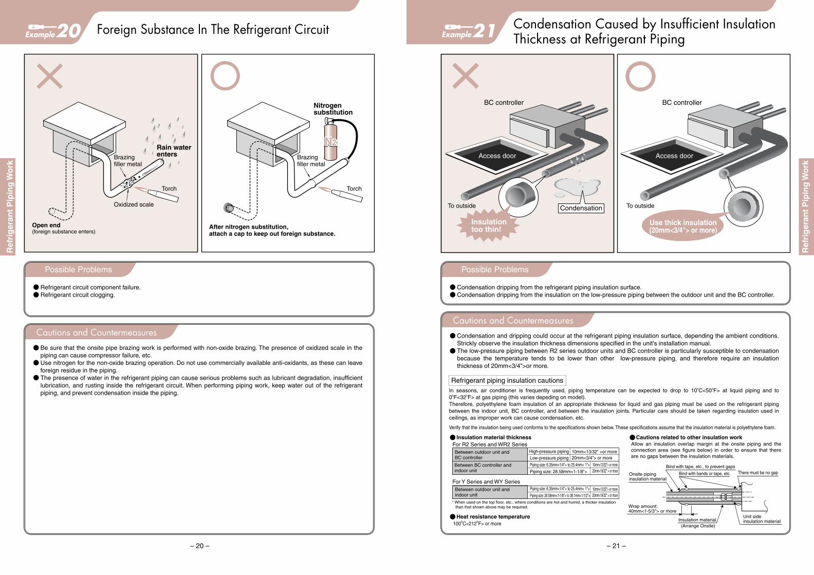
Condensation Caused by Insufficient InsulationThickness at Refrigerant PipingExample21
BC controller BC controller
Access door Access door
To outside To outside
Insulationtoo thin!
Condensation
Use thick insulation(20mm<3/4"> or more)
Possible Problems
Condensation dripping from the refrigerant piping insulation surface.Condensation dripping from the insulation on the low-pressure piping between the outdoor unit and the BC controller.
Cautions and CountermeasuresCondensation and dripping could occur at the refrigerant piping insulation surface, depending the ambient conditions. Strickly observe the insulation thickness dimensions specified in the unit's installation manual.The low-pressure piping between R2 series outdoor units and BC controller is particularly susceptible to condensation because the temperature tends to be lower than other low-pressure piping, and therefore require an insulation thickness of 20mm<3/4">or more.
In seasons, air conditioner is frequently used, piping temperature can be expected to drop to 10oC<50oF> at liquid piping and to 0oF<32oF> at gas piping (this varies depeding on model).Therefore, polyethylene foam insulation of an appropriate thickness for liquid and gas piping must be used on the refrigerant piping between the indoor unit, BC controller, and between the insulation joints. Particular care should be taken regarding insulation used in ceilings, as improper work can cause condensation, etc.
Verify that the insulation being used conforms to the specifications shown below. These specifications assume that the insulation material is polyethylene foam.
Refrigerant piping insulation cautions
Allow an insulation overlap margin at the onsite piping and the connection area (see figure below) in order to ensure that there are no gaps between the insulation materials.
Insulation material thickness Cautions related to other insulation work
Heat resistance temperature100oC<212oF> or more
For R2 Series and WR2 Series
For Y Series and WY Series
Between outdoor unit andBC controller
High-pressure piping
Piping size: 6.35mm<1/4"> to 25.4mm< 1">Piping size: 28.58mm<1-1/8">
Low-pressure piping10mm<13/32"> or more20mm<19/32" > or more
10mm<13/32"> or more20mm<19/32" > or more
Between BC controller andindoor unit
* When used on the top floor, etc., where conditions are hot and humid, a thicker insulation than that shown above may be required.
Between outdoor unit andindoor unit
Piping size: 6.35mm<1/4"> to 25.4mm< 1">Piping size: 28.58mm<1-1/8"> to 38.1mm<1/1/2">
Onsite pipinginsulation material
Bind with tape, etc., to prevent gaps
Bind with bands or tape, etc. There must be no gap
Unit sideinsulation materialInsulation material
(Arrange Onsite)
Wrap amount:40mm<1-5/3"> or more
10mm<13/32" >or more20mm<3/4"> or more
Example
– 20 –
Foreign Substance In The Refrigerant Circuit
Nitrogensubstitution
Torch Torch
After nitrogen substitution, attach a cap to keep out foreign substance.
Rain waterentersRain waterenters
Possible Problems
Refrigerant circuit component failure.Refrigerant circuit clogging.
Cautions and CountermeasuresBe sure that the onsite pipe brazing work is performed with non-oxide brazing. The presence of oxidized scale in the piping can cause compressor failure, etc.Use nitrogen for the non-oxide brazing operation. Do not use commercially available anti-oxidants, as these can leave foreign residue in the piping.The presence of water in the refrigerant piping can cause serious problems such as lubricant degradation, insufficient lubrication, and rusting inside the refrigerant circuit. When performing piping work, keep water out of the refrigerant piping, and prevent condensation inside the piping.
20
Open end (foreign substance enters)
Brazingfiller metal
Brazingfiller metal
Oxidized scale
Ref
rig
eran
t P
ipin
g W
ork
Ref
rig
eran
t P
ipin
g W
ork

Example
– 23 –
Gas Leakage Due to Improper Flare Work
Possible Problems
Gas leakage will occur if connected with an improper flare.
Cautions and Countermeasures1. Pipe cut
Use a pipe cutter, and cut the copper pipe gradually so as not to deform it.
2. Deburr and cut surface cleaningA poor end-face shape (after deburring) or cutting chips adhered to the flare area will cause refrigerant leakage. To prevent this, position the pipe with its cut face down, and gently clean off the cutting chips.
4. When reusing existing piping, be sure to rework the piping to the prescribed R410A flare requirements.
* The R410A working pressure is approximately 1.6 times that of R22, and gas leakage will therefore occur if the piping is not reworked.
3. Use a R410A dedicated flare tool (clutch type) to perform the flare work.[Check items]The flare face must have a uniform width with a glossy surface.The thickness of flare area must be uniform.The flare size must be appropriate.
23
Example of poor flare work
Insufficientburr removal
Inner surface scratchesdue to cutting chips, etc.
Insufficient flaredimension
Excessive flaredimension
Cracking
Gap
A
D
※ ※
* The perimeter length must be uniform.
A faulty connection will result in gas leakage, and must be repaired.
[mm<inch>]
6.35
9.52
12.7
15.88
19.05
R410A
9.1<0.364>
13.2<0.528>
16.6<0.664>
19.7<0.788>
24.0<0.96>
R22 R407C
9.0<0.36>
13.0<0.52>
16.2<0.648>
19.4<0.776>
23.3<0.932>
+0-0.4
Deburring procedure
Rotate left and right to remove the burrs from the inner side of the copper pipe.
When using a reamer, remove the burrs with the copper pipe facing downward.
Flare work dimensions
Flare work
Pipe outerdiameter D
A dimension
Example
– 22 –
Incorrect Additional Refrigerant Charging
Tank color codes: Brown = R407CPink = R410A
Charging with the R410A tank upside down Tank with syphon pipe
Chargingtank Charging
tank
Do not charge withthe R410A tankupside down.
Refrigerantcomposition changes
Valve
Liquid
Possible Problems
The R407C and R410A refrigerants are mixtures of two or more refrigerant types which have differing evaporation temperatures. R410A tank is equipped with a syphon pipe, for when charging with gas, the quick-evaporating refrigerant is charged, and the slow-evaporating refrigerant remains in the charging tank. Turning a syphon-equipped tank upside down when charging can alter the refrigerant composition, resulting in reduced performance or malfunctions.
Cautions and Countermeasures<Cautions before recharging>
(1) Verify the gas tank's refrigerant.(2) Verify if the tank have a syphon pipe.(3) Place the electronic force balance on a hard, flat surface.(4) Do not use a charging cylinder as this could alter the refrigerant composition, resulting in performance loss.
<Cautions when recharging>(1) Recharge from the stop valve after vacuumizing the extension pipe and the indoor unit.
(when unit is not in operation)(2) When recharging from the suction side check valve, use a safety charger, etc., to prevent the liquid refrigerant from
being sucked in directly. (when unit is in operation)(3) At the gauge manifold's sight glass, verify that liquid is charged. Note also that the charge hose vibrates if liquid is
being charged. Grasp the charge hose to verify that it is vibrating. If gas is being charged, check the tank type.
22
<Insufficient refrigerant amount>Insufficient refrigerant causes performance loss and compressor heating which will cause the unit to make an emergency stop.
<Excessive refrigerant amount>Over-charging with refrigerant will dilute oil by refrigerant, resulting in poor compressor lubrication and compressor failuredue to liquid compression.
Ref
rig
eran
t P
ipin
g W
ork
Ref
rig
eran
t P
ipin
g W
ork

Example
– 25 –
Combining of horizontal drain piping
Cautions and Countermeasures
Cautions and Countermeasures
Possible Problems Possible Problems
25
660mm
190mm
850mm
Riser of drain piping
Long distance from unit to the riser
No downward slope on drain piping due to the blocking beam
Trap on the way of horizontal piping
(Note)
(Note) Be careful that the drain pump is an optional item for some models. Also please note that the drain head differs by models.
After raising the drain piping, a downward slope of more than 1/100 is to be provided. However, if a convex part is provided on the way, drain does not flow normally but flows reversely to the drain pan side leading to overflow. Arrange the distance from the unit to the riser part as short as possible, and posture the riser pipe at a right angle. Neglecting the above will cause overflow.
Follow the instruction below to raise the drain piping.Make sure to bond the connection part of the piping.
Thermal insulation material
Main unit
Thermal insulation material
Main unit
Field piping
Field piping
Field piping
Field piping
Ceiling surfaceCeiling surface
Field pipingDownward slope of 1/100 or more
Band (small)
Band (small)Band (large) Band (large)
1 2(As short as possible) 200mm<8"> or less Flexible hose (As short as possible)
300mm<12"> or lessSupport metal fitting Support metal fitting
Field pipingDownward slope of 1/100 or more
1. As the drain riser height differs depending on models, please consult the Installation Manual. - 4-way ceiling cassette type (PLFY/V-BM): Within 850mm<34"> from the ceiling surface
1 1
Flexible hose
Horizontal or slightly rising slope
If there is a trap on the way of horizontal drain piping, the drain flow is hindered and sludge is bred from ac-cumulated dust at the bottom of the trap. This gener-ates clogging which may lead to overflow.
Never provide a trap or deflection as shown above. Check the structure which will be an obstacle like a beam beforehand, and determine the position from which the piping is taken out for connection. When deflection is a problem, support the necessary points on the piping.
Trap on drain piping
<26">
<7-1/2">
<34">
– 24 –
Example24 Air mixed in refrigerant piping or air conditioning unit
Shorter evacuation time
Air
Air
Vacuum pump
with backflow prevention adapter
Charge hose
Brazing
Evacuation system diagram
Compound gauge
Handle Low Open
–101kPa
Charge hose (exclusive for R410A)
Pressure gauge
Gauge manifold (exclusive for R410A)
Handle High Close
Vacuum gauge(recommended product)
No flange
No flare
Possible Problems
The condensing pressure increases abnormally during operation resulting in compressor loss, which may degrade the capacity or shorten the life of the compressor. In addition, the protective device tripped may stop the compressor.If water content is mixed even in a very small amount, the water content freezes inside the expansion valve or capillary
Cautions and CountermeasuresFor air purging at the installation of equipment, do not apply the gas purge method but apply the evacuation method for reliable operation.When using pipe sold in the market, make sure to evacuate the pipe as it is containing air.
<Points of vacuum drying>1. Evacuate from the service port of the stop valve by using a vacuum pump with
high performance for a sufficient time [more than 1 hour after reaching –101kPa (5 Torr)] to perform vacuum drying inside the piping,
2. Checkup is required when the vacuum degree does not drop to –101kPa (5 Torr) after 1~2 hours, for there may be a leaking spot or water content entering the piping.
3. When the vacuum degree is high, mixing of water content may be assumed. In order to remove the water content inside the piping, pressurize nitrogen gas up to 0.5kgf/cm2 and evacuate again. Repeat this operation until the pressure
reaches below –101kPa(5 Torr) or the pressure rise is eliminated. (If nitrogen gas is not charged, water content cannot be removed as the water content inside the piping will freeze.)
4. The evacuation time differs depending on the capacity of a vacuum pump to be used or the amount of the water contained. Therefore you are requested to execute vacuum drying by observing the vacuum degree carefully not sticking to the time only.
5. Mixing of the vacuum pump oil into the HFC group refrigerant cycle by reverse flow will be a major cause to damage the equipment.
(Maintenance management of vacuum pump)With many vacuum pumps, the water content contained in air may mix into oil frequently at discharging air inside the refrigerant piping. Therefore, checking of the vacuum pump for a proper oil quantity, and conducting of periodic oil replacement are essential. (Please provide a periodical maintenance by following the Instruction Manual of the vacuum pump.)
–101kPa(5 Torr)
Leaving (1 hour)
Time
Pressure
Atmospheric pressure
Possible leaking or mixing of water content
Normal
Evacuation (1~ 2 hours)
Dra
in P
ipin
g W
ork
Ref
rig
eran
t P
ipin
g W
ork

Cautions and Countermeasures
Example
– 27 –
Combining of horizontal drain piping
Possible Problems
27
100mm<4"> or more (as distant as possible)
Make sure to bring down nearer the unit as possible
Slope of 1/100 or more
Size the collective piping thicker than the connecting piping to the unit.
(Note)Do not provide an air vent to models equipped with the drain pump.
At the stopping of the unit due to stagnated drain flow, the backflow of the drain causes overflow from the drain pan.
1. For the collective piping, use 1-rank thicker piping than the connecting piping with the unit.2. Make sure to locate the collective piping more than 100mm<4"> lower than the connecting piping with the unit.3. Provide a downward slope of more than 1/100 to the collective piping.4. Do not install an air vent as inner pressure is applied to piping by the drain pump.5. Make sure to apply adhesive jointing to the connection of the drain piping.
Example
– 26 –
Troubles about horizontal drain piping26
(Note) Since inner pressure is applied to the drain piping of models provided with the drain pump, please do not install an air vent.
Air vent
As inner pressure is being applied by the drain water lift-up mechanism, installing of an air vent may cause to blow out water. During the stopping of the drain pump, in addition, drain water accumulated in the air vent may flow reversely causing overflow from the drain pan.
1. Make sure to provide a slope of 1/100 or more to the horizontal drain piping.
2. Make sure to bond the connections of piping.
3. Do not install an air vent to a model using the drain pump as inner pressure is being applied to piping.
4. Arrange the horizontal drain piping length less than 20m. (For a longer drain piping, install support metal fittings on the piping to eliminate the waving of it.)
Intermediate sup-port metal fitting (for each 2m~3m)
Slope of 1/100 or more
Waving
Support the piping as shown below to prevent waving.
Provide a support metal fitting near the unit.
Possible Problems
Cautions and Countermeasures
Dra
in P
ipin
g W
ork
Dra
in P
ipin
g W
ork

Example
– 29 –
Water Leakage From Drain Pipe Connection Area
Excessivetensile force
Pay attention tosuspension boltdistance
Connection pullsloose due to
excessive tensile force!
Indoorunit
Indoorunit
Suspensionbolt
Secure connection
Possible Problems
Water (drain) leakage.
Cautions and CountermeasuresBe sure to use a prescripted adhesive (for hard vinyl chloride pipe) when connecting the indoor unit's accessory drain hose. Using other adhesives could result in water leakage.
29Example
– 28 –
Entry of odor/corrosive gas from drain piping
Offensive odor entering the room from sewage ditch
Offensive odor
Avoid to lead drain piping directly to a spot generating offensive odor.
28
Possible Problems
Offensive odor (corrosive gas) will be brought into the room through drain piping if the drain piping is led down into a sewer ditch where offensive odor is likely to be generated.Some types of gas will corrode the heat exchanger, which may lead to gas leak.
Cautions and CountermeasuresIt is essential to avoid from leading drain piping directly to a spot likely generating offensive odor.
Brazing filler steel peeling
A blackened copper pipe indicates gas leakage from thebrazing area (occurs most often at ceiling-suspended types).
Environment Drain pipe is led down into a sewer ditch.
Draining the water into a sewer ditch can cause gas leakage at the brazing area due to corrosive gas which flows from the drain pipe.
Discoloredto black
Hydrogen sulfide (sulfur system) gas.
Corrosion (phosphorous selective corrosion) in brazing area where water leakage occured when cooling.
Use a corrosion-resistant item with epoxy resin applied tothe copper pipe (including brazing areas).
Install a dedicated for drain water.
Problemmechanism
Preventivemeasures
Problemcause
Possibleproblem
<Example for ceiling-suspended type>
Dra
in P
ipin
g W
ork
Dra
in P
ipin
g W
ork

Example
– 31 –
Malfunctions Due To Using the Same PowerSupply and Ground Devices as the Outdoor Unit
Transmission Errors Related to theTransmission Line Type and Length31
Example
32
TB3: Indoor/outdoor transmission line terminal blockTB7: Centralized transmission terminal block
TB3
TB7
TB3
TB7
TB3
TB7
TB3
TB7
TB3
TB7
TB3
TB7
Indoor unit
2 conductor shielded
2 conductor shielded
Outdoor unit
Remote controller
Use a 2-conductor cable.
OK
380V
Broadcastingsystem
Outdoor unitwith inverter
3-phase 4-wirepower supply
TB3: Indoor/outdoor transmission line terminal blockTB7: Centralized transmission terminal block
Indoor unitTB3
TB7
TB3
TB7
TB3
TB7
TB3
TB7
TB3
TB7
TB3
TB7
The use of a multi conductor transmits cableother system signals through the cable trunking.
Multi conductor cable
Outdoor unit
Remote controller
Possible Problems
Transmission error.
Using a multiconductor cable in transmission lines for multiple refrigerant systems can cause transmission errors.Loop unnecessary transmission lines in the ceiling, and keep the lines as short as possible in order to prevent signal attenuation and error stops.Use shielded cables for M-NET transmission lines.
Cautions and Countermeasures
Possible Problems
Malfunctions, etc., occur during air-conditioner operation at units which share a power supply or ground device.Noise interference occurs on sound systems during air-conditioner operation.
Noise is transmitted via the power supply and ground. In VRF systems, use a dedicated power supply and ground device for each unit.Separate and do not share powersupply when having two devices.
Cautions and Countermeasures
380V
3-phase 4-wirepower supply
Broadcastingsystem
Noise
Zap
Outdoor unitwith inverter
Example
– 30 –
Selecting a Breaker For Ground fault
Power supply
* For details, contact the breaker manufacturer.
* The above-mentioned is one example.
High frequencyleakage current
Non-inverter-compliant breaker
will causeunnecessary
shutoffs.
Groundfaultbreaker
L1
N
L2L3
Inverter
Load
220415
Inverter-compliantbreaker
Cautions and CountermeasuresBe sure to install a ground Fault breaker.
The leakage current increases with inverter devices.Inverter models first convert the AC power supply to DC, then convert it to the desired frequency AC with ON/OFF of high-speed switching element. The current leakage in these models are therefore greater than that in constant-speed models (non-inverter models), and may cause unnecessary shutoffs due to the capacitive coupling to the ground.To prevent such unnecessary shutoffs, use a ground fault breaker which is resistant to high-frequency current leakage (known as high-frequency surge resistant breakers, etc.).
Because the amount of current leakage varies according to the power cable size and length, kefer to instllation Manual or instraction book for specific breaker value.
Special care should be taken when changing from a constant-speed device to an inverter device.
Possible Problems
Ground fault breaker is tripped at inverter operations.
30
Wir
ing
Wo
rk
Wir
ing
Wo
rk
Example
– 32 –
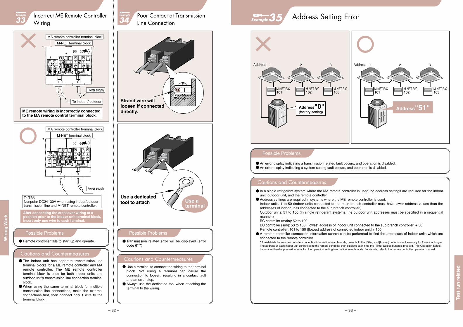
Incorrect ME Remote ControllerWiring
Poor Contact at TransmissionLine Connection33
Example
34
After connecting the crossover wiring at aposition prior to the indoor unit terminal block, insert only one wire to each terminal.
Power supply
Power supply
MA remote controller terminal block
M-NET terminal block
MA remote controller terminal block
To TB5Nonpolar DC24~30V when using indoor/outdoortransmission line and M-NET remote controller.
M-NET terminal block
ME remote wiring is incorrectly connectedto the MA remote control terminal block.
To indoor / outdoor
Possible Problems
Remote controller fails to start up and operate.
The indoor unit has separate transmission line terminal blocks for a ME remote controller and MA remote controller. The ME remote controller terminal block is used for both indoor units and outdoor unit's transmission line connection terminal block.When using the same terminal block for multiple transmission line connections, make the external connections first, then connect only 1 wire to the terminal block.
Cautions and Countermeasures
Possible Problems
Transmission related error will be displayed (error code 6***)
Use a terminal to connect the wiring to the terminal block. Not using a terminal can cause the connection to loosen, resulting in a contact fault and an error stop.Always use the dedicated tool when attaching the terminal to the wiring.
Cautions and Countermeasures
Use aterminal
Strand wire willloosen if connecteddirectly.
Use a dedicatedtool to attach
– 33 –
Example35 Address Setting Error
Possible Problems
An error display indicating a transmission related fault occurs, and operation is disabled.An error display indicating a system setting fault occurs, and operation is disabled.
Cautions and CountermeasuresIn a single refrigerant system where the MA remote controller is used, no address settings are required for the indoor unit, outdoor unit, and the remote controller.Address settings are required in systems where the ME remote controller is used.Indoor units: 1 to 50 (indoor units connected to the main branch controller must have lower address values than the addresses of indoor units connected to the sub branch controller.)Outdoor units: 51 to 100 (In single refrigerant systems, the outdoor unit addresses must be specified in a sequential manner.)BC controller (main): 52 to 100.BC controller (sub): 53 to 100 ([lowest address of indoor unit connected to the sub branch controller] + 50)Remote controller: 101 to 150 ([lowest address of connected indoor unit] + 100)A remote controller connection information search can be performed to find the addresses of indoor units which are connected to the remote controller.
Address 1
M-NET R/C101
M-NET R/C102
M-NET R/C103
2 3
Address"0"(factory setting)
Address 1
M-NET R/C101
M-NET R/C102
M-NET R/C103
2 3
Address"51"
* To establish the remote controller connection information search mode, press both the [Filter] and [Louver] buttons simultaneously for 2 secs. or longer. The address of each indoor unit connected to the remote controller then displays each time the [Timer Select] button is pressed. The [Operation Select] button can then be pressed to establish the operation setting information search mode. For details, refer to the remote controller operation manual.
Test
ru
n r
elat
ed
Wir
ing
Wo
rk

– 35 –
Example37 Incorrect MELANS System Configuration
Possible Problems
Selecting the wrong power meter (with pulse generating function) will result in a mismatch between the power meter reading used in the charge calculation system and the actual consumption.
Error (mismatch) between the charge calculation system output and the power meter reading.
Cautions and CountermeasuresIf the power amount per pulse is large on power meters with pulse generating functions, the amount of error in the air-conditioning charge calculation system's output will also be large.The air-conditioning charge calculation management value represents the power meter (with pulse generating function) value which is proportionally divided in accordance with their operating conditions among all the air-conditioners connected to a power supply. Therefore, the calculate value may differ from the power meter value for each unit.Test operation should be performed in accordance with the installation manuals, with all the items listed on the charge calculation test operation check-sheet (wiring, devices used, settings, etc.) being thoroughly checked.
If the WHM amount increases 100kWh, the TG-2000A may register this as only 90kWh at a "1 pulse = 10kWh" WHM.
Incorrect pulse units settingIf a "1 pulse = 10kWh" WHM is set at the TG-2000 as a "1 pulse = 1kWh" WHM, the TG-2000 output will be only 1/10 of the actual power consumption.
Powersupply
Powersupply
WHM
TG-2000Acharge calculation system
G-50A
Tenant A 72kWh 70kWhTenant B 28kWh 20kWh
Actual value Tenant A 72kWhTenant B 28kWh
1 pulse =10kWh
1 pulse =1kWh
Value onlyincreases every
10kwh
WHM
G-50A
90kWh
Tenant A
1 pulse =1kWh
72kWh
28kWh
100kWh
70kWh
20kWh
90kWh 100kWh
1 pulse =10kWh
10kWh difference
Meter Increase Amount
Tenant B
Illustration Explanation
Other cases
Total
TG-2000Acharge calculation system
100kWh
– 34 –
Example36 Mismatch When Changing the Address Setting
G-50 G-50
1 2 4
3
11 12 13
Change4
3Change
1 2
11 12 13
Group setting
1,2,3…Group setting
1,2,4…
Possible Problems
Transmission error.System error.
Cautions and CountermeasuresWhen changing an address (for indoor unit, outdoor unit, remote controller, branch controller) in a system where a centralized controller is used, be sure to also change the group setting at the centralized controller. After revising the setting, reset the centralized controller.Failing to change the centralized controller's group setting will result in an error at the centralized controller.At test operations, check each unit's operation individually first without the centralized controller, then check each unit's operation individually again with the centralized controller.
Test
ru
n r
elat
ed
Test
ru
n r
elat
ed

Example
– 37 –
Compressor Failure ImmediatelyAfter Power ON39
Example
40 Using AUTO Cooling/Heating Mode
Remote controller's built-in thermostat
Possible Problems
Compressor failure.
In VRF systems turn the outdoor unit power on 12 hours before operation to allow the compressor crankcase heater to heat the crankcase and expel the liquid refrigerant which has collected in the compressor.Starting the compressor with liquid refrigerant collected inside will cause the bearing to be insufficiently lubricated and cause liquid compression.
Cautions and Countermeasures
Possible Problems
When using ceiling cassette or ceiling concealed type indoor units in the AUTO heating/cooling mode, cool blowing air may be felt during the heating season.
When using ceiling cassette or ceiling concealed type indoor units in the AUTO heating/cooling mode, "use remote thermostat (optional item: PAC-SE41TSA) or the remote controller thermostat setting.
Cautions and Countermeasures
Refrigerantmovement
Crankcaseheater
Liquid refrigerant emission outside the compressorwhen crankcase heater is turned on.
Power ON for12 hours or longer
Refrigerantmovement
Power OFF
Bearing damagewhen started
Crankcaseheater
Large amount of liquid refrigerantinside the compressor.
Scroll damage
Following a heating thermostat OFF, the cooling thermostat switches ON when the temperature rises 1.5oC<34.7oF> above the setting temperature.
Suction thermostat
Alternating warmand cool airemission
– 36 –
Example38 Valve Operation After Vacuumizing the Onsite Piping
outdoor unit outdoor unit
Valve
Refrigerant service valve OPENImmediateoperationvalve OPEN
Possibility ofa compressorfailure.
Large movement ofrefrigerant and oil insidethe outdoor unit.
Onsite pipingvacuum completed Charging onsite piping with refrigerant.
Valve
Possible Problems
Compressor failure
Opening the outdoor unit's valve before the vacuumized onsite piping has been charged with refrigerant will result in an abrupt pressure change inside the outdoor unit, causing the compressor to expel its internal oil. This could result in a bearing lubrication fault when the compressor starts.
Cautions and Countermeasures
Test
ru
n r
elat
ed
Test
ru
n r
elat
ed

Guide to installation
The specifications, designs and information in this brochure are subject to change without notice.
November. 2008, Printed in Japan
AIR CONDITIONING SYSTEMS
For Internal Training