Sun City Air Conditioning | Grand Canyon Air Conditioning, Heating, Solar

INVESTIGATION OF A SOLAR-ASSISTED THERMALLY ACTIVATED
AIR CONDITIONING SYSTEM
Muhammad Mujahid Rafique
MECHANICAL ENGINEERING
November 2015

KING FAHD UNIVERSITY OF PETROLEUM & MINERALS
DHAHRAN- 31261, SAUDI ARABIA
DEANSHIP OF GRADUATE STUDIES
This thesis, written by Muhammad Mujahid Rafique under the direction of his thesis
advisor and approved by his thesis committee, has been presented and accepted by the
Dean of Graduate Studies, in partial fulfillment of the requirements for the degree of
MASTER OF SCIENCE IN MECHANICAL ENGINEERING.
_______________________
Dr. Zuhair Mattoug Gasem Department Chairman
_______________________
Dr. Salam A. Zummo Dean of Graduate Studies
__________________ Date
________________________
Dr. Palanichamy Gandhidasan (Advisor)
________________________
Dr. Luai M. Al-Hadhrami (Member)
________________________
Dr. Haitham M.S. Bahaidarah (Member)

iii
© Muhammad Mujahid Rafique
2015
ALL RIGHTS RESERVED

iv
Dedicated to my beloved parents, brothers, sisters, cousins and
friends, whose constant prayers, sacrifice and inspiration led to
this wonderful accomplishment

v
ACKNOWLEDGMENT
“In the name of Allah, The Most Gracious and Most Merciful”
All praises to Allah Almighty, for giving me patience and courage to complete my thesis
work. My due acknowledgements to King Fahd University of Petroleum & Minerals for
providing me this opportunity to accomplish my M.S. With due respect, I would like to
thank my advisor Dr. Palanichamy Gandhidasan for his continuous guidance and help
through all the difficult stages. I would like to acknowledge the help from my committee
members, Dr. Haitham M.S. Bahaidarah and Dr. Luai M. Al-Hadhrami.
I would like to extend my thanks to the Heat Engine laboratory engineer Mr. Karam for his
help in experimental work. I thank all my fellow graduate students at KFUPM for making
my stay at KFUPM a memorable and enjoyable one. Special thanks to my parents, brothers
and sisters for their encouragement, support and constant prayers for my success.

vi
TABLE OF CONTENTS
ACKNOWLEDGMENT ............................................................................................................... V
TABLE OF CONTENTS ............................................................................................................. VI
LIST OF TABLES ......................................................................................................................... X
LIST OF FIGURES ...................................................................................................................... XI
NOMENCLATURE .................................................................................................................... XV
ABSTRACT ............................................................................................................................ XVIII
الرسالة ملخص ................................................................................................................................. XX
CHAPTER 1 INTRODUCTION ................................................................................................. 1
1.1 Energy and environmental issues ..................................................................................................... 4
1.2 Human comfort and building indoor air quality ............................................................................... 6
1.3 Alternative cooling systems and dehumidification ........................................................................... 6
1.4 Background ...................................................................................................................................... 7
CHAPTER 2 DESICCANT BASED EVAPORATIVE COOLING ........................................ 10
2.1 Introduction ................................................................................................................................... 10
2.2 Basic principle and types of evaporative cooler ............................................................................. 11
2.3 Desiccant dehumidifier .................................................................................................................. 17
2.4 Desiccant based evaporative cooling ............................................................................................. 19
2.4.1 General idea .................................................................................................................................. 19
2.4.2 System description......................................................................................................................... 22
2.4.3 Literature survey ............................................................................................................................ 23
2.5 Advantages of desiccant-aided evaporative cooling ...................................................................... 31
vii
2.6 Major applications of desiccant based evaporative cooling ........................................................... 32
2.7 Performance Index......................................................................................................................... 32
2.8 Modified evaporative cooler .......................................................................................................... 34
2.9 Developments in evaporative cooling research .............................................................................. 40
2.10 Conclusions .................................................................................................................................. 43
CHAPTER 3 LITERATURE REVIEW OF LIQUID DESICCANT MATERIALS AND
DEHUMIDIFIER ........................................................................................................................ 46
3.1 Introduction .................................................................................................................................. 46
3.2 Liquid desiccant cooling ................................................................................................................ 47
3.3 Performance parameters .............................................................................................................. 48
3.4 Advantages of using liquid desiccants ........................................................................................... 49
3.5 Liquid desiccant materials ............................................................................................................. 52
3.6 Composite desiccant materials ..................................................................................................... 56
3.7 Liquid desiccant dehumidifiers ..................................................................................................... 59
3.8 Adiabatic dehumidifiers ............................................................................................................... 60
3.9 Dehumidifier with inner cooling ................................................................................................... 67
3.10 Developments of liquid desiccant dehumidifier ........................................................................... 76
3.11 Dehumidifier packing material selection ...................................................................................... 81
3.12 Flow pattern inside the dehumidifier ........................................................................................... 83
3.13 Conclusions .................................................................................................................................. 85
3.14 Objectives of the present work .................................................................................................... 87
CHAPTER 4 MATHEMATICAL MODELING OF LIQUID DESICCANT WHEEL ......... 88
4.1 Introduction .................................................................................................................................. 89
4.2 Mathematical modeling ................................................................................................................ 93
4.2.1 System description ...................................................................................................................... 93

viii
4.2.2 Modeling approach ..................................................................................................................... 94
4.2.3 Governing equations ................................................................................................................... 95
4.3 Boundary and initial conditions ................................................................................................... 97
4.4 Performance index ...................................................................................................................... 98
4.5 Results and discussions ................................................................................................................ 99
4.5.1 Feasibility analysis ..................................................................................................................... 100
4.5.2 Parametric analysis .................................................................................................................... 104
4.6 Conclusions ............................................................................................................................... 113
CHAPTER 5 EXPERIMENTAL INVESTIGATION OF LIQUID DESICCANT
COOLING CYCLE…… ............................................................................................................. 116
5.1 Introduction ................................................................................................................................ 116
5.2 Test facility ................................................................................................................................. 117
5.3 Desiccant preparation ................................................................................................................. 122
5.4 Instrumentations ........................................................................................................................ 122
5.5 Test procedure and conditions .................................................................................................... 123
5.6 Uncertainty analysis .................................................................................................................... 124
5.7 Performance parameters ............................................................................................................ 126
5.8 Results and discussion ................................................................................................................ 128
5.8.1 Effect of ambient air humidity ratio .......................................................................................... 128
5.8.2 Effect of ambient air temperature ............................................................................................ 132
5.8.3 Effect of process air mass flux ................................................................................................... 135
5.8.4 Effect of regeneration air mass flux .......................................................................................... 138
5.8.5 Effect of regeneration temperature .......................................................................................... 140
5.8.6 Effect of desiccant concentration .............................................................................................. 143

ix
5.9 Comparison of heat and mass transfer model of liquid desiccant dehumidifier with
experimental data ....................................................................................................................... 145
5.10 Conclusions ................................................................................................................................. 152
CHAPTER 6 FEASIBILITY ANALYSIS OF SOLID DESICCANT COOLING SYSTEM
UNDER CLIMATIC ZONE OF DHAHRAN, SAUDI ARABIA ......................................... 154
6.1 Introduction ............................................................................................................................... 155
6.2 Description of solid desiccant cooling cycles .............................................................................. 156
6.3 Simulation Model ....................................................................................................................... 158
6.4 Cycle analysis ............................................................................................................................. 160
6.5 Performance Index ..................................................................................................................... 161
6.6 Results and discussion................................................................................................................ 161
6.7 Conclusions ................................................................................................................................ 171
CHAPTER 7 CONCLUSIONS AND FUTURE WORK ...................................................... 173
7.1 Conclusions ................................................................................................................................. 173
7.2 Recommendations for future work ............................................................................................. 175
REFERENCES.......................................................................................................................... 177
VITAE ....................................................................................................................................... 196

x
LIST OF TABLES
Table 2.1: Types and characteristics of evaporative cooling systems. ............................. 17
Table 2.2: Summary of different studies related to evaporative cooling systems. ........... 41
Table 2.3: Needed R & D for desiccant based evaporative cooling technology [121]. .... 43
Table 3.1: Performance parameters used for liquid desiccant cooling systems. .............. 49
Table 3.2: Comparison between liquid-desiccant cooling system and conventional air- conditioning system. ....................................................................................... 51
Table 3.3: Weighing factors and figures of merit for desiccant selection [154]. .............. 59
Table 3.4: Details of Adiabatic/internally cooled dehumidifiers. ..................................... 85
Table 4.1: Overview of thermal cooling techniques [228]. .............................................. 91
Table 4.2: Liquid vs. solid desiccant air conditioning [230]. ........................................... 91
Table 4.3: Operating and geometric parameters. ............................................................ 100
Table 5.1: Specifications of sensors................................................................................ 123
Table 5.2: Uncertainties of measuring instruments used in experiment. ........................ 125
Table 5.3: Operating parameters. .................................................................................... 128
Table 6.1: Meteorological Data of Dhahran, Saudi Arabia for the month of April (15th April). .................................................................................................. 162
Table 6.2: Meteorological Data of Dhahran, Saudi Arabia for the month of July (17th July). .................................................................................................... 163
Table 6.3: Meteorological Data of Dhahran, Saudi Arabia for the month of October (15th October). .............................................................................................. 163
Table 6.4: Operating parameters. .................................................................................... 164
xi
LIST OF FIGURES
Figure 1.1: Thermal comfort zone according ASHRAE 55 [1]. ......................................... 1
Figure 1.2: The functions of air conditioning [2]. .............................................................. 2
Figure 1.3: Interrelation between energy, environment and technologies issues to the nature and humanity survival [7]. ..................................................................... 4
Figure 1.4: Long-lived greenhouse gases concentrations in atmospheric [12]. .................. 5
Figure 1.5: Methods for the conversion of solar energy into air conditioning or cooling process [21]. ...................................................................................................... 7
Figure 1.6: Graphical representation of the world energy consumption [23]. .................... 8
Figure 1.7: HVAC equipment demand and annual growth [27]. ....................................... 9
Figure 2.1: Cooling process representation of indirect evaporative cooler on psychrometric chart. ....................................................................................... 13
Figure 2.2: The schematic of the indirect evaporative cooler [37]. .................................. 14
Figure 2.3: Flow arrangement inside indirect cooler [38]. ............................................... 14
Figure 2.4: Direct evaporative cooler (a) schematic diagram (a) psychrometric process [40]. ................................................................................................................. 15
Figure 2.5: Psychrometric Chart showing the Enthalpy Change used to determine Capacity [46]. .................................................................................................. 16
Figure 2.6: Dehumidification and regeneration process of a desiccant dehumidifier [52]. ................................................................................................................ 18
Figure 2.7: Different configurations for various desiccant system [53]. .......................... 18
Figure 2.8: Principle of the thermally activated evaporative desiccant cooling systems [59]. ................................................................................................................. 20
Figure 2.9: Desiccant evaporative cooling system operating on ventilation cycle [64]. 21
Figure 2.10: Desiccant evaporative cooling system operating on recirculation cycle [64]. .............................................................................................................. 21
Figure 2.11: Desiccant evaporative cooling system operating on Dunkle Cycle [65]...... 22
Figure 2.12: A simple schematic of experimental desiccant cooling system in ventilation mode, and its psychrometric chart representation for a typical operation [66]. .............................................................................................. 23
Figure 2.13: Schematic of compact cross flow type plate heat exchanger [76]. .............. 26
Figure 2.14: Schematic diagram of the standard desiccant cooling system with pre-cooling and DEC [91]. .................................................................................. 30
Figure 2.15: Schematic diagram of the standard desiccant cooling system with pre-cooling [91]. ................................................................................................. 30
Figure 2.16: The schematic of the two-stage evaporative cooler [92]. ............................. 35
Figure 2.17: The psychrometric process representation of the two-stage evaporative cooler. ........................................................................................................... 36
Figure 2.18: Modern Evaporative Cooling Media (Source: Munter). .............................. 38
Figure 2.19: Schematic diagram of modified indirect evaporative cooler [112]. ............. 39

xii
Figure 2.20: Schematic of indirect evaporative cooler to achieve dew point temperature of the incoming air [39]. ........................................................... 39
Figure 3.1: Heat and mass exchanger configurations for various desiccant cooling technologies [133]. ......................................................................................... 51
Figure 3.2: Different desiccant materials isotherms for water adsorption [150]. ............. 57
Figure 3.3: A liquid desiccant dehumidification system with liquid-liquid heat exchanger [163]. ............................................................................................. 62
Figure 3.4: Desiccant bed details [177]. ........................................................................... 65
Figure 3.5: (a) Overall view of the system; (b) Cross-sectional view; (c) Side view [178]. .............................................................................................................. 66
Figure 3.6: Schematic diagram of dehumidifier with inner cooling [180]. ...................... 68
Figure 3.7: Spaced parallel plate packing material dehumidifier with inner cooling [183]. ............................................................................................................... 69
Figure 3.8: Inner cooled dehumidifier with finned tube [184]. ........................................ 70
Figure 3.9: Inner cooled dehumidifier (cross flow): (a) directions of air flow (b) fluid sprays contacting with different air streams [176]. ......................................... 72
Figure 3.10: A new type of internally cooled/heated dehumidifier/regenerator [189]. .... 74
Figure 3.11: Schematic of internally cooled/heated liquid desiccant dehumidification [191]. ............................................................................................................ 75
Figure 3.12: Schematic of spray type internally cooled dehumidifier [192]. ................... 76
Figure 3.13: Multi-stage liquid desiccant dehumidifier [135]. ......................................... 77
Figure 3.14: Dehumidifier/regenerator with auxiliary cooling/heating module [193]. .... 77
Figure 3.15: Two-stage liquid desiccant dehumidification system [195]. ........................ 78
Figure 3.16: Structure of a parallel-plate membrane module [199].................................. 79
Figure 3.17: Internally cooled vertical flat plate dehumidifier [95]. (a) Side view; (b) Inner view. .................................................................................................... 80
Figure 3.18: Internally cooled dehumidifier with corrugated plates [201]. ...................... 80
Figure 3.19: Schematic diagram of hollow fiber membrane module type multistage dehumidifier [193]. ....................................................................................... 81
Figure 4.1: Schematic of rotary liquid desiccant dehumidifier......................................... 94
Figure 4.2: Pattern of flow in a slot. ................................................................................. 95
Figure 4.3: Monthly variations of DCOP, latent effectiveness, moisture removal capacity, and SER. ........................................................................................ 103
Figure 4.4: Hourly variations of DCOP, latent effectiveness, moisture removal capacity, and SER. ........................................................................................ 103
Figure 4.5: Effect of process air mass flux on heat and mass transfer coefficients. ....... 105
Figure 4.6: Effect of process air mass flux on outlet air humidity ratio. ........................ 106
Figure 4.7: Effect of process air flux on the latent effectiveness and DCOP. ................ 107
Figure 4.8: Effect of inlet air humidity ratio on the latent effectiveness and DCOP. ..... 108

xiii
Figure 4.9: Effect of rotational speed on DCOP for different regeneration temperatures. ................................................................................................ 109
Figure 4.10: Effect of rotational speed on DCOP for different mass flow rate ratios. ... 110
Figure 4.11: Effect of rotational speed on dehumidifier moisture removal capacity for different process air mass flow rate. ..................................................... 110
Figure 4.12: Effect of inlet air conditions on sensible energy ratio for different ambient air temperatures. ........................................................................... 112
Figure 4.13: Effect of mass flow rates ratio on sensible energy ratio for different regeneration temperatures. ......................................................................... 113
Figure 5.1: Schematic of experimental setup. ................................................................. 118
Figure 5.2: Photographic view of experimental setup. ................................................... 119
Figure 5.3: (a) Desiccant wheel; (b) direct evaporative cooler; (c) indirect evaporative cooler. ....................................................................................... 121
Figure 5.4: Psychrometric representation of desiccant cooling cycle. ............................ 122
Figure 5.5: Effect of ambient air humidity ratio on: (a) COP; (b) ECOP; (c) TCOP; (d) moisture removal rate; (e) DCOP; (f) sensible energy ratio. ................. 132
Figure 5.6: Effect of ambient temperature on: (a) COP; (b) ECOP; (c) TCOP; (d) moisture removal rate; (e) DCOP; (f) sensible energy ratio. ....................... 135
Figure 5.7: Effect of process air mass flux on: (a) COP; (b) ECOP; (c) TCOP; (d) moisture removal rate; (e) DCOP; (f) sensible energy ratio. ....................... 138
Figure 5.8: Effect of regeneration air mass flux on: (a) COP; (b) TCOP; (c) DCOP; (d) sensible energy ratio. .............................................................................. 140
Figure 5.9: Effect of regeneration temperature on: (a) COP; (b) TCOP; (c) moisture removal rate; (d) DCOP; (e) sensible energy ratio. ..................................... 143
Figure 5.10: Effect of desiccant concentration on: (a) moisture removal rate; (b) DCOP; (c) sensible energy ratio. .......................................................... 144
Figure 5.11: Comparative results for effects of ambient air humidity ratio on: (a) moisture removal rate; (b) DCOP; (c) sensible energy ratio. ............... 147
Figure 5.12: Comparative results for effects of ambient air temperature on: (a) moisture removal rate; (b) DCOP; (c) sensible energy ratio. ............... 148
Figure 5.13: Comparative results for effects of process air mass flux on: (a) moisture removal rate; (b) DCOP; (c) sensible energy ratio. .................................... 150
Figure 5.14: Comparative results for effects of regeneration temperature on: (a) moisture removal rate; (b) DCOP; (c) sensible energy ratio. ............... 151
Figure 6.1: Microbial growth as a function of relative humidity [241]. ......................... 156
Figure 6.2: (a) Systematic solid desiccant cooling system with indirect evaporative cooler (b) psychrometric processes. ............................................................ 159
Figure 6.3: Variations of moisture removal from the process air during the day. .......... 165
Figure 6.4: Variations of wheel effectiveness on process side during the day. .............. 165
Figure 6.5: Variations of wheel effectiveness on regeneration side during the day. ...... 166

xiv
Figure 6.6: Variations of cooling effect produced during the day. ................................. 168
Figure 6.7: Variations of required regeneration load during the day. ............................. 168
Figure 6.8: Variations of COP during the day. ............................................................... 169
Figure 6.9: Variations of COP for different ratios of mass flow rates. ........................... 169
Figure 6.10: Variations of required regeneration load for different ratios of mass flow rates and regeneration temperature. ................................................... 170
Figure 6.11: Variations of cooling effect for different process air flow rates. ............... 170
Figure 6.12: Variations of moisture removal capacity for various process air mass flow rates. ................................................................................................... 171

xv
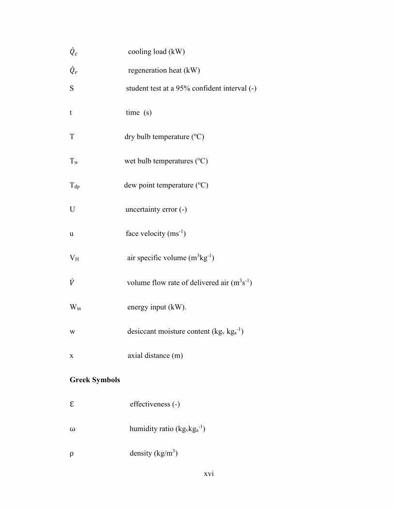
NOMENCLATURE
A channel area (m2)
Cp specific heat (kJkg-1 oC -1)
ht heat transfer coefficient (kWm-2 K-1)
h specific enthalpy (kJkg-1)
hfg latent heat of vaporization (kJkg-1).
k mass transfer coefficient (kgm-2 s-1)
L dehumidifier width (m)
�� mass flow rate (kgs-1)
���� mass flow rate of water vapor at inlet of evaporative cooler (kgs-1)
���� mass flow rate of water vapor at outlet of evaporative cooler (kgs-1)
��� evaporation rate of water (kgs-1)
M moisture removal rate (kgs-1)
ND number of data points (-)
N number of cells in each slot (-)
pv vapor pressure (kPa)
� sensible cooling capacity (kW)
� total cooling capacity (kW)
xvi
�� cooling load (kW)
�� regeneration heat (kW)
S student test at a 95% confident interval (-)
t time (s)
T dry bulb temperature (oC)
Tw wet bulb temperatures (oC)
Tdp dew point temperature (oC)
U uncertainty error (-)
u face velocity (ms-1)
VH air specific volume (m3kg-1)
� volume flow rate of delivered air (m3s-1)
Win energy input (kW).
w desiccant moisture content (kgv kga-1)
x axial distance (m)
Greek Symbols
ℇ effectiveness (-)
ω humidity ratio (kgvkga-1)
ρ density (kg/m3)

xvii
� standard deviation (-)
� degree of freedom (-)
Subscripts
1, 2, 3… state points
a air
c cross sectional
d desiccant material
f wall material
h internal surface
i inlet
o outlet
p process
r regeneration
s desiccant surface
v vapor
w liquid water
xviii
ABSTRACT
Full Name : Muhammad Mujahid Rafique
Thesis Title : Investigation of a solar assisted thermally activated air conditioning system
Major Field : Mechanical Engineering
Date of Degree : November 2015
In the Kingdom of Saudi Arabia, a vast amount of energy is used for air conditioning. One
of the objectives of this work is to develop solar assisted energy-efficient air conditioning
system using desiccant technology with compact components, suitable for households
since the demand for domestic production capacity of window type unitary unit is about
74%. On the east and west coastal regions of the Kingdom, the temperature and humidity
are high during the summer months. Dehumidification of air in hot and humid conditions
is as important as cooling and removal of moisture from the air is much easier to achieve
than cooling the air. Thus air is used as the energy transfer fluid in the proposed system.
The proposed technology is based on chemical dehumidification of air followed by
evaporative cooling. The major energy required for the proposed system is low grade
thermal energy such as solar energy for the regeneration of the desiccant.
In order to make the system compact and to be used as the window type unit, rotor disc is
used for the dehumidifier. The proposed system works at atmospheric conditions and hence
the construction is simpler. The proposed system offers an environmental friendly air
conditioning system. It provides 100% fresh air without the application of
chlorofluorocarbon and other similar refrigerants. A laboratory scale experimental facility

xix
has been fabricated to evaluate the performance of a desiccant based air conditioning
system and to validate the proposed theory.

xx
ملخص الرسالة
محمد مجاھد رفيق :اسم الكامل
.ياستكشاف نظام تكييف ھواء جديد يعتمد على الطاقة الشمسية ويشغل بالحث الحرار عنوان الرسالة:
الھندسة الميكانيكية التخصص:
2015تاريخ الدرجة العلمية: نوفمبر
قتراحا� ھذا أھداف وأحد. الھواء لتكييف السعودية العربية المملكة في الطاقة من ھائلة كمية تستھلكيا ومستخدما التكنولوج للطاقة موفرا يكون الشمسية الطاقة بمساعدة للھواء تكييف نظام تطوير ھو
من يالمحل ا�نتاج على الطلب أن حيث المنزلي ، ستخدامل� ومناسبا المجففة ذات المكونات المدمجة والمناطق الشرقي الجانب على تقع التي للمباني بالنسبة و. ٪74 اليحو يبلغ النوافذ تكييف وحدات
الةوإز. الصيف أشھر خ�ل مرتفعتان والرطوبة الحرارة درجة تكون المملكة، من الغربية الساحلية لجوا من الرطوبة إزالةفي ا�جواء الساخنة والرطبة لھا من ا�ھمية كالتبريد حيث الھواء من الرطوبة
.رحالمقت النظام في للطاقة ناقل كسائل الھواء استخدام يتم ثم ومن. الھواء تبريد من بكثير أسھل
ثابت التبخيري ريدبالتب ثم المجفف السائل باستخدام للھواء الكيميائي التجفيف على التقنية ھذه وتستند اقةالط مثل الدرجة منخفضة حرارية طاقة أي ھي المقترح للنظام ال�زمة الرئيسية الطاقة و. الحرارة .المجففة المادة إنتاج إعادة أجل من الشمسية
حدةبو الدوران أقراص استخدام سيتم نافذة، كوحدة ل�ستخدام وقاب� متوافقا النظام جعل أجل ومنام فيكون . وھذا النظأسھل يكون تركيبه فإن ثم ومن الجوي الضغط عند يعمل المقترح والنظام التكييف،
بدون أية تطبيقات % 100أنظمة التكييف الصديقة للبيئة حيث أنه يزودنا بھواء منعش بنسبة من أخرى من الكلوروفلوروكربون أو ما شابھھا من المبردات. ثم أنه أيضا تم تنفيذ تجارب في المختبر
لتقييم أداء أنظمة التكييف المعتمدة على المجفف �ثبات النظرية المقترحة.

1
1 CHAPTER 1
INTRODUCTION
In order to provide the human comfort indoor conditions, the cooling requirements should
not be mentioned in terms of sensible cooling capacity (temperature control) only but latent
cooling (control of humidity) should also be included especially for hot and humid outdoor
conditions. The range of human comfort conditions and basic requirements for the human
comfort need to be provided by the air conditioning system are illustrated in Fig. 1.1 [1]
and Fig. 1.2 [2], respectively.
Figure 1.1: Thermal comfort zone according ASHRAE 55 [1].
2
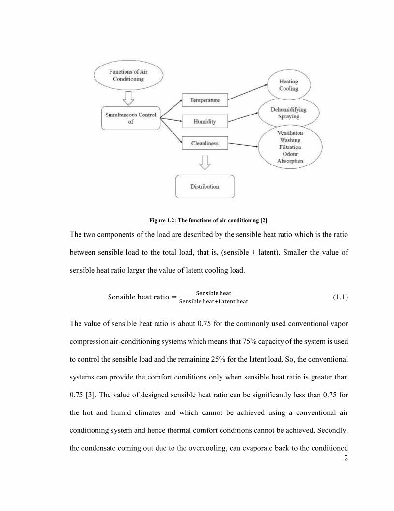
Figure 1.2: The functions of air conditioning [2].
The two components of the load are described by the sensible heat ratio which is the ratio
between sensible load to the total load, that is, (sensible + latent). Smaller the value of
sensible heat ratio larger the value of latent cooling load.
Sensible heat ratio = !"#$%&'" (")*!"#$%&'" (")*+,)*"#* (")* (1.1)
The value of sensible heat ratio is about 0.75 for the commonly used conventional vapor
compression air-conditioning systems which means that 75% capacity of the system is used
to control the sensible load and the remaining 25% for the latent load. So, the conventional
systems can provide the comfort conditions only when sensible heat ratio is greater than
0.75 [3]. The value of designed sensible heat ratio can be significantly less than 0.75 for
the hot and humid climates and which cannot be achieved using a conventional air
conditioning system and hence thermal comfort conditions cannot be achieved. Secondly,
the condensate coming out due to the overcooling, can evaporate back to the conditioned
3
space which may result in increased humidity level in the comfort zone [4]. These problems
of conventional air conditioning systems can be addressed using a technology called
desiccant cooling. This technology is a combination of a desiccant dehumidifier and
evaporative cooler. The only energy used in this system is to drive the fans, water pump
and to regenerate the desiccant dehumidifier during the regeneration process. This energy
can be provided from any low grade thermal energy source such as solar, waste heat, etc.
The sensible and latent loads can be controlled separately in this system using a humidistat
and thermostat for the control of wet and dry bulb temperatures, respectively. This system
can operate on wide range of sensible heat ratios because of the decoupling of sensible and
latent cooling loads.
The simple evaporative cooler is not useful in hot and humid climates. Under such
conditions, an evaporative cooling system can be used in conjunction with other
dehumidification systems which can extract the water vapor from the air. This deficiency
of the evaporative cooling system can be overcome by using it in combination with
desiccant dehumidifier to dry the air. The application of adsorbent based dehumidification
will allow the effective use of direct as well as indirect evaporative coolers in hot and
humid climates [5,6].
4
1.1 Energy and environmental issues
The fast depletion of conventional energy resources and increasing demand of human
comfort conditions because of increase in world population is becoming a major global
environmental issue. These issues of energy, environment and technology are interrelated
and for clean and greener environment these issues must be treated simultaneously and
with interconnectivity as shown in Fig. 1.3 [7].
Figure 1.3: Interrelation between energy, environment and technologies issues to the nature and humanity survival [7].
5
A large amount of greenhouse gases are emitted due to the burning of conventional energy
resources. The emission of CO2 is increasing every year mostly because of economic
development and fast increase in population in developing countries of the world. The use
of air conditioning and heating devices plays a major role in the emission of these gases
which causes depletion of ozone layer and other environmental issues [8-10]. All of these
cause an increase in global temperature which causes many climatic and weather
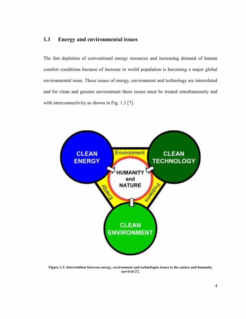
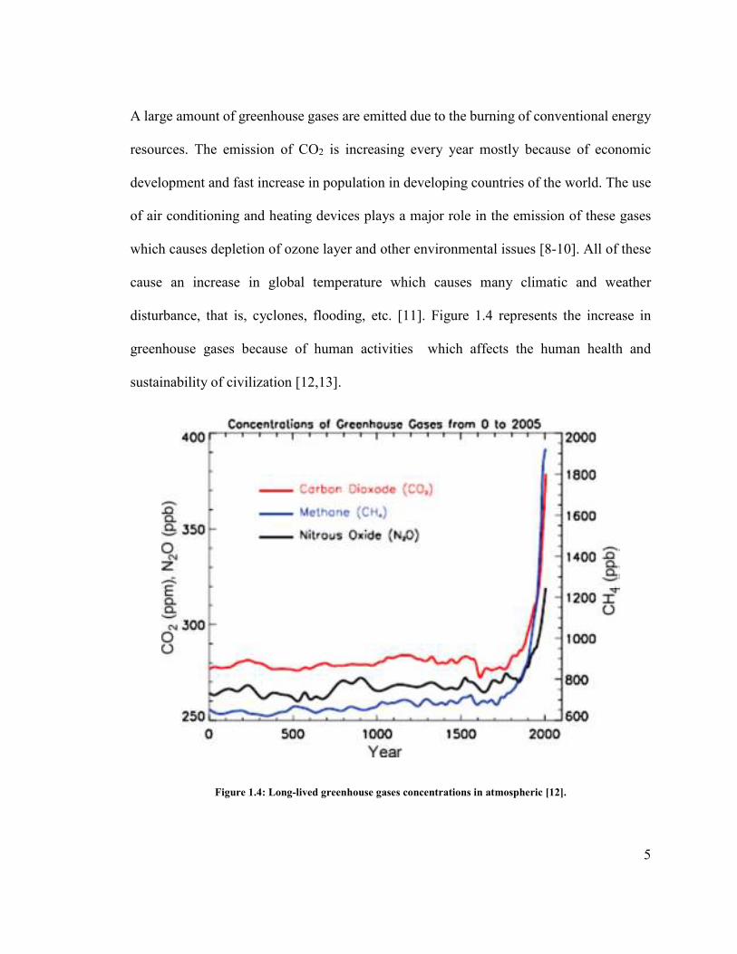
disturbance, that is, cyclones, flooding, etc. [11]. Figure 1.4 represents the increase in
greenhouse gases because of human activities which affects the human health and
sustainability of civilization [12,13].
Figure 1.4: Long-lived greenhouse gases concentrations in atmospheric [12].
6
1.2 Human comfort and building indoor air quality
Because of the fact that indoor environment is mostly used for human activities so,
residential as well as commercial buildings uses a large amount of primary energy for its
maintenance and to support its occupant’s activities [14]. This demand of energy is
expected to increase because of increase in population and higher standards of living which
directly affects the energy consumption. It is expected that the consumption of electrical
energy for indoor environment will increase 120% from 2002 to 2030 [15]. The
consumption of electrical energy for the agricultural sector increases to 56.7% in 2006 from
44.2% in 1973. The energy required to provide human thermal comfort conditions (control
of temperature and relative humidity) is about 50% of building total energy consumption
which in most cases is in the form of electrical energy [16].
1.3 Alternative cooling systems and dehumidification
In order to reduce the consumption of energy and to reduce the greenhouse gases emissions
some alternative methods are required to provide the thermal comfort conditions and better
indoor air quality [17]. These alternative systems reduces the building energy consumption
largely through the utilization of some alternative resources of energy, for example, solar,
biomass etc. [18]. Some alternative thermal cooling systems which directly utilizes the
thermal energy are desiccant cooling, absorption cooling and jet cooling [19]. Solar energy
can be effectively used for these systems because of variation in cooling load in phase
with the solar radiation during the day [20]. Figure 1.5 illustrates some methods to convert

7
the solar energy for the purpose of air conditioning [21, 22]. In Fig. 1.5 market available
solar assisted systems are represented as dark grey and technologies available as pilot
projects are marked as light grey. The thermal cooling system utilizes thermal energy to
provide the cooling effect.
Figure 1.5: Methods for the conversion of solar energy into air conditioning or cooling process [21].
1.4 Background
The primary sources of energy, that is, oil, natural gas (NG), and coal are being consumed
largely as compared to the renewable and environment friendly energy resources such as
8
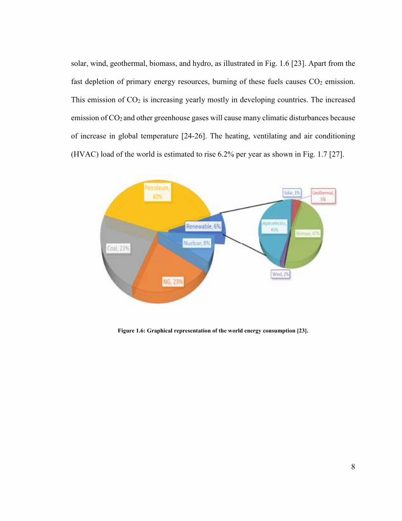
solar, wind, geothermal, biomass, and hydro, as illustrated in Fig. 1.6 [23]. Apart from the
fast depletion of primary energy resources, burning of these fuels causes CO2 emission.
This emission of CO2 is increasing yearly mostly in developing countries. The increased
emission of CO2 and other greenhouse gases will cause many climatic disturbances because
of increase in global temperature [24-26]. The heating, ventilating and air conditioning
(HVAC) load of the world is estimated to rise 6.2% per year as shown in Fig. 1.7 [27].
Figure 1.6: Graphical representation of the world energy consumption [23].

9
Figure 1.7: HVAC equipment demand and annual growth [27].
The renewable energy which was not utilized so well in the past is gaining attention now
because of competitive cost, commercial acceptance, ease of maintenance and operation,
and its environment friendly nature. Major part of the primary energy consumed in the
building is accounted for cooling or heating. So in order to reduce the emission of CO2 and
CFCs to the environment the need of the alternative/s to the conventional cooling systems
is needed which could make use of renewable energies in a better way.
The proposed research is to design, develop and operate the solar assisted energy-efficient
air conditioning system using desiccant technology. The system is constructed in the
laboratory at King Fahd University of Petroleum and Minerals with monitoring system to
measure the performance of the developed system.

10
2 CHAPTER 2
DESICCANT BASED EVAPORATIVE COOLING
2.1 Introduction
3 The air conditioner should control the building sensible and latent load properly in order
to provide the indoor comfort conditions. The conventional mechanical vapor compression
system usually controls the latent load by the process of condensation of water vapor in
which air is cooled below its dew point temperature and then reheated again up to the
required supply conditions. The conditions where latent load is dominant these two
processes i.e. overcooling and then reheating again will increase the consumption of
electrical energy and emission of CO2 remarkably. To avoid this wastage of primary energy
and emission of harmful gases, desiccant based evaporative cooling system is a good
alternative to traditional air conditioning system which is cost effective as well as
environment friendly. It can be driven by thermal energy which makes a good use of solar
energy which is free as well as clean.
4 The evaporative coolers appeared around 2500 B.C., when porous clay jars containing
water were used by the ancient Egyptians for air cooling purpose. This evaporative cooling
mechanism was applied to cool the ancient Egypt buildings and then spread across the hot
region of Middle East. Similar types of mechanism to produce the cooling effect in the
building also appeared at that time such as pools, water ponds, porous water pots, and thin
water chutes. The evaporative coolers of modern type were started in USA. Several air
conditioning devices which included indirect as well as direct evaporative coolers were

11
also invented in Arizona and California [28]. Many residential and commercial spaces
were equipped with water dripping air coolers in Southwest, in late 1930s. In early 1950s,
these air coolers were developed and available in wide range of market places including
Canada, USA, and Australia.
5 In this chapter, a review of desiccant based evaporative cooling systems has been
presented. The present study is undertaken from variety of aspects including background
and need of alternative cooling systems, concept of conventional and desiccant based
evaporative coolers, system configurations, operational modes, as well as current status of
the desiccant based evaporative cooling technology. The review work indicated that the
technology of desiccant based evaporative cooler has a great potential of providing human
thermal comfort conditions in hot and humid climatic conditions at the expense of less
primary resources of energy as compared to conventional cooling systems. Some modified
and modern evaporative coolers have also been introduced in this chapter.
6
2.2 Basic principle and types of evaporative cooler
As mentioned previously, a well suitable alternative of mechanical vapor compression
system is evaporative cooling system which can be efficiently used for air conditioning
applications with less power requirements i.e. one fourth of the mechanical vapor-
compression. It is an energy saving, cost effective, simple, and environment friendly air
conditioning technique. Many researchers have investigated different types of evaporative
coolers such as direct, indirect and modified coolers [29, 30].

12
Evaporative cooling systems are suitable for dry and high temperature climatic conditions
[31]. These units can be used as direct contact evaporative cooling unit [32,33], indirect
contact evaporative cooling [34,35] or as combination of both. Technologies exist which
makes use of evaporative cooler to cool down the air without adding moisture content to it
is commonly known as indirect evaporative cooling [36]. In the indirect evaporative system
the process air stream does not interact directly with the cooling fluid stream rather it is
cooled sensibly. The cooling process inside an indirect evaporative cooler is represented
on psychrometric chart shown in Fig. 2.1. The temperature of air is lowered using some
type of heat exchange arrangement in which primary air is cooled sensibly using a
secondary air stream. The secondary air is cooled using water. In the indirect evaporative
cooling system, both dry as well as wet bulb temperature of the air are lowered. The indirect
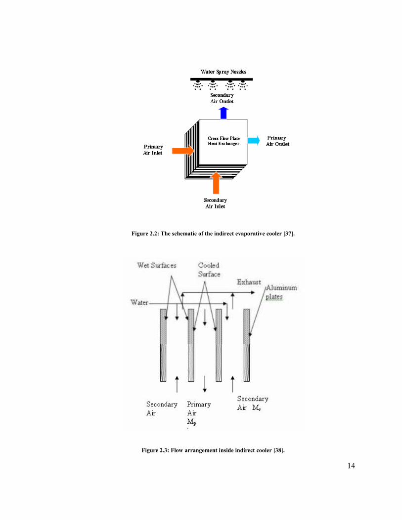
evaporative cooling has an efficiency of 60-70%. The schematic and flow arrangements
inside the indirect evaporative cooler is shown in Fig. 2.2 [37] and Fig. 2.3 [38],
respectively.
In direct evaporative system moisture is also added to the cooled air stream because process
air stream comes in direct contact with the cooling water. In direct evaporative cooling
system, the temperature of the process air is lowered because of the high moisture content
in the air so it is an adiabatic process which is only suitable for hot and dry climates and
for hot and humid climates indirect evaporative cooler is preferred. In the direct
evaporative cooling dry bulb temperature of the air is lowered and wet bulb temperature
remains unchanged. The wet bulb temperature is an important parameter for the
performance of direct evaporative cooler. The effectiveness of a well-made direct

13
evaporative cooler reaches an effectiveness of approximately 85% [39]. Both the schematic
and psychrometric process of the direct evaporative cooler is shown in Fig. 2.4 [40]. The
ambient air comes in direct contact with the spayed water which decreases the temperature
of the supply air and adds moisture content to it as shown on the psychrometric chart. The
transfer of heat and mass between process hot air and cooling water for a direct evaporative
cooler is expressed as [41],
. . . . .
1 1 1 21 1 2 2( ) ( )v w vv fg vm h m h m h m h m h+ − = + (2.1)
Sensible cooling
Dry bulb temperature (oC)
Hum
idity
rat
io (
kg/k
g of
dry
air
)
DB2 DB1
DPT
WB1
WB2
h1
h2
12
DPT-Dew point temperature, WB-Wet bulb temperature, DB-Dry bulb temperature
Figure 2.1: Cooling process representation of indirect evaporative cooler on psychrometric chart.
14
Figure 2.2: The schematic of the indirect evaporative cooler [37].
Figure 2.3: Flow arrangement inside indirect cooler [38].

15
Figure 2.4: Direct evaporative cooler (a) schematic diagram (a) psychrometric process [40].
The process of indirect evaporative cooling needs input energy only for the water pump
and fan that is why this system has high coefficient of performance. Camargo et al. [42]
presented the evaporative cooling principles to achieve the human thermal comfort for
indoor conditions. The principle of porous ceramics indirect evaporative cooler was
presented by Riffat and Zhu [43]. The results showed that under dry and windy conditions,
a high cooling capacity of the system can be achieved. It was also concluded in [43] that
the better performance of the cooler can be achieved with reasonable velocity of the indoor
air (0.6 ms-1) and by increasing the thermal conductivity of heat pipe condenser. The air
flow passage dimensions, air ratio (process to intake), and velocity of air are main
parameters which defines the effectiveness and energy efficiency of a counter flow heat
and mass exchanger while temperature of the feed water has less effect on effectiveness
[44]. Similarly, the heat and mass transfer is less affected by the thermal properties (thermal
conductivity and porosity) of the material used for heat and mass transfer in an indirect

16
evaporative cooler while cost, shape formation, holding ability, durability, compatibility
with water-proof coating become the main factors of concern [45].
The difference of cooling processes of mechanical cooling system and direct evaporative
cooler on psychrometric chart is illustrated in Fig. 2.5 [46]. The chart shows that a greater
value of mass flow rate is required for evaporative cooler as compared to conventional air
conditioner in order to control the same cooling load because of smaller enthalpy
difference. Figure 2.5 also illustrates that under the same operating conditions the resulting
humidity of the supply air will be much higher with the evaporative cooler as compared to
the conventional air conditioners. Performance comparison and characteristics of different
types of evaporative cooling system is presented in Table 2.1.
Figure 2.5: Psychrometric Chart showing the Enthalpy Change used to determine Capacity [46].

17
Table 2.1: Types and characteristics of evaporative cooling systems.
Type Technology
status
Comfort impact Energy savings
potential
Effectiveness
Direct Mature Humidity Increase 70% 80-90%
Indirect Early production No humidity
increase
50% About 85%
Indirect-Direct Early production Slight humidity
increase
80% 110%
2.3 Desiccant dehumidifier
The desiccant dehumidifier composed of a desiccant material which removes moisture
from the air by the process of dehumidification. Different desiccant materials attracts the
moisture from the air at different capacities [47]. The desiccant materials can be solid as
well as liquid. Silica gel, calcium chloride, lithium bromide, lithium chloride, activated
ammonia and natural zeolite are the most commonly used desiccants. The desiccant
dehumidifier is regenerated using thermal energy. Several researchers used solar energy as
the input source for regeneration of desiccant dehumidifier [48-50]. The standard method
which is mostly utilized is rotating desiccant wheel embedded with silica gel or lithium
chloride [51]. The process of dehumidification and regeneration of a desiccant
dehumidifier is illustrated in Fig. 2.6 [52]. The desiccant removes moisture from the air (1-
2) and desiccant is regenerated by removing moisture from it using hot air (2-3). During
process (3-1) desiccant is cooled down again. Solar energy can be used effectively to
provide heat for regeneration. Ahmed et al. [53] stated the different possibilities to use solar

18
energy for regeneration in solid desiccant systems. The desiccant dehumidifier can be of
different configurations which are illustrated in Fig. 2.7.
Figure 2.6: Dehumidification and regeneration process of a desiccant dehumidifier [52].
Figure 2.7: Different configurations for various desiccant system [53].

19
2.4 Desiccant based evaporative cooling
2.4.1 General idea
In general, evaporative cooling systems are applied when the wet bulb temperature does
not exceed much beyond 25°C frequently [54]. The evaporative cooling units can operate
with a high coefficient of performance (COP) in dry climatic conditions [55]. But because
of the air saturation of the surrounding air in humid climates, the effectiveness of these
cooling units drops remarkably. That is why evaporative cooler is best suited in conjunction
with the desiccant dehumidifier, which removes the moisture from the process air and thus
these cooling units can function effectively. The desiccant dehumidifier composed of some
desiccant material (silica gel, lithium chloride, lithium bromide etc.) which is used to
remove the moisture from the moist air. A desiccant material is one which absorbs or
adsorbs and hold water vapor from the humid air by the process of absorption or adsorption
[56,57]. The evaporative desiccant cooling system compromises of a desiccant
dehumidifier, a regenerator, and a cooling unit [58]. The basic working principle of a
thermally activated evaporative desiccant cooling system is illustrated in Fig. 2.8 [59]. The
air is dehumidified using desiccant dehumidifier and its temperature is lowered using
evaporative cooler or some other cooling device. For continuous operation of the system
the desiccant dehumidifier is regenerated by using thermal energy provided by solar
collectors or some other source of energy as shown in Fig. 2.8. Some heat recovery units
are also utilized to make the system more efficient.

20
Thermal collector
Desiccant dehumidifier Heat recovery
Direct/indirect evaporative cooler Auxiliary cooler
Renewable energyNon-conventional energy
Conventional energy
Heat energy
Outdoor hot and humid air
Latent heat removal
Heat energy
Hot and dehumidified air Warm and
dehumidified air
Sensible heat removal
Cool and dehumidified air
Supply airCool and dry air
Sensible heat removal Renewable energy
Non-conventional energy Conventional energy
Figure 2.8: Principle of the thermally activated evaporative desiccant cooling systems [59].
In desiccant based evaporative cooling technique, latent and sensible loads are separately
removed using desiccant dehumidification system and cooling unit, respectively. The type
of cooling units used to reduce the temperature of dehumidified air, mainly defines the type
of hybrid desiccant cooling system. The selection of the cooling unit depends on operating
conditions, that is, humidity and temperature of the air. The most commonly used cycles
for desiccant based evaporative cooling systems are recirculation [60], ventilation [61],
Dunkle and wet surface heat exchangers [62]. Dezfouli et al. [63] compared the
performance of solar desiccant cooling system operating on ventilation and recirculation
mode under the climatic conditions of Malaysia. They concluded that the system has a
coefficient of performance 0.8 and 1.6 under ventilation and recirculation mode,
21
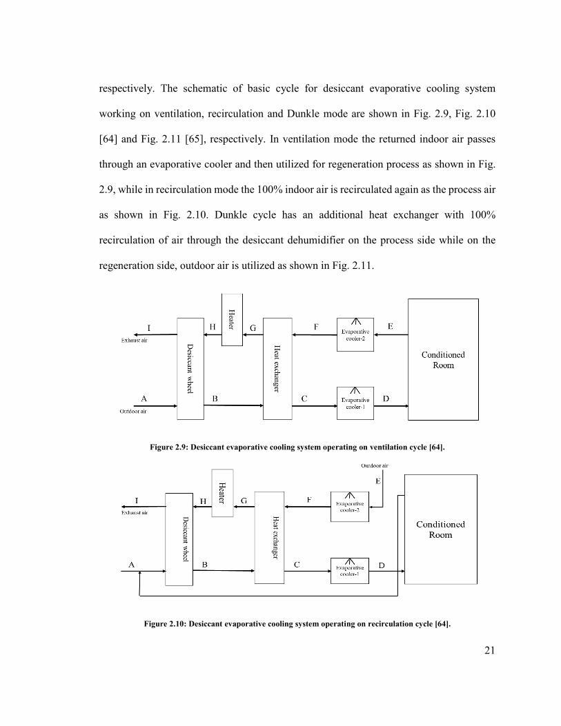
respectively. The schematic of basic cycle for desiccant evaporative cooling system
working on ventilation, recirculation and Dunkle mode are shown in Fig. 2.9, Fig. 2.10
[64] and Fig. 2.11 [65], respectively. In ventilation mode the returned indoor air passes
through an evaporative cooler and then utilized for regeneration process as shown in Fig.
2.9, while in recirculation mode the 100% indoor air is recirculated again as the process air
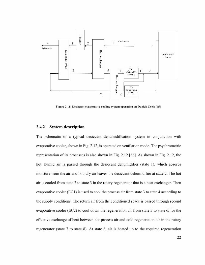
as shown in Fig. 2.10. Dunkle cycle has an additional heat exchanger with 100%
recirculation of air through the desiccant dehumidifier on the process side while on the
regeneration side, outdoor air is utilized as shown in Fig. 2.11.
Figure 2.9: Desiccant evaporative cooling system operating on ventilation cycle [64].
Figure 2.10: Desiccant evaporative cooling system operating on recirculation cycle [64].
22
Figure 2.11: Desiccant evaporative cooling system operating on Dunkle Cycle [65].
2.4.2 System description
The schematic of a typical desiccant dehumidification system in conjunction with
evaporative cooler, shown in Fig. 2.12, is operated on ventilation mode. The psychrometric
representation of its processes is also shown in Fig. 2.12 [66]. As shown in Fig. 2.12, the
hot, humid air is passed through the desiccant dehumidifier (state 1), which absorbs
moisture from the air and hot, dry air leaves the desiccant dehumidifier at state 2. The hot
air is cooled from state 2 to state 3 in the rotary regenerator that is a heat exchanger. Then
evaporative cooler (EC1) is used to cool the process air from state 3 to state 4 according to
the supply conditions. The return air from the conditioned space is passed through second
evaporative cooler (EC2) to cool down the regeneration air from state 5 to state 6, for the
effective exchange of heat between hot process air and cold regeneration air in the rotary
regenerator (state 7 to state 8). At state 8, air is heated up to the required regeneration

23
temperature using a heat source to regenerate the desiccant material in desiccant wheel.
Then the air is exhausted to the atmosphere at state 9 and the cooling cycle is completed.
DW: desiccant wheel, RR: rotary regenerator, EC1: evaporative cooler 1, EC2: evaporative cooler 2
Figure 2.12: A simple schematic of experimental desiccant cooling system in ventilation mode, and its psychrometric chart representation for a typical operation [66].
2.4.3 Literature survey
The desiccant evaporative cooling systems lead a remarkable reduction in electrical energy
consumption as compared to conventional units and it also reduces the number of
discomfort hours inside the conditioned space [67]. Uçkan et al. [68] presented the first
experimental results of a desiccant based evaporative cooling system for hot and humid

24
climatic conditions. The evaporative cooler used by Uçkan et al. in their experiment is of
indirect type (IEC). The results showed that the ambient air can be cooled down to 19°C
from 31°C and a continuous supply of air at 25°C can be maintained to a conditioned space.
Riangvilaikul and Kumar [69] proposed and tested an indirect evaporative cooling unit to
reduce the temperature of the air leaving the desiccant dehumidifier without disturbing the
humidity of air. The results showed a good performance of the system for both humid and
dry outdoor conditions. The system resulted in a dew point effectiveness of 0.58-0.84 and
wet-bulb effectiveness of 0.9-1.14, [69]. Instead of the evaporative cooler, a heat exchanger
was used by Katejanekarn and Kumar [70] to lower the temperature of dry air coming from
the desiccant dehumidifier without adding moisture to the air.
Parmar and Hindoliya [71] studied the potential of a solid desiccant based direct
evaporative cooler for the climatic conditions of five cities of India and compared the
performance of the system for all the cities. The 50% return air from the conditioned space
was mixed with the regeneration air and the remaining 50% with the process air. The results
showed that system COP for different cities varies between 0.14 and 0.21. The best
performance of the system was observed under the conditions of coastal city (Mumbai). It
was also concluded that the inlet humidity of the air and effectiveness of the direct
evaporative cooler have a strong effect on the system performance. The system
effectiveness increases 30-50% with the 15% increase in effectiveness of evaporative
cooler. A cooling system using liquid desiccant dehumidifier using lithium bromide as
liquid desiccant in conjunction with direct evaporative cooler without the circulation of air
was proposed by Oliveira et al. [72]. The simulation results showed that this alternative
25
novel air conditioning system has a great potential to replace conventional air conditioning
systems with initial cost lower than the conventional system.
Kessling et al. [73] experimentally tested liquid desiccant system in conjunction with the
indirect evaporative cooler using a desiccant solution of lithium chloride which can be
regenerated at low temperature of about less than 80°C. Wurtz et al. [74] studied the
cooling potential of desiccant based evaporative cooling system for the climatic conditions
of France using simulation model and validated the results experimentally. The results
showed that system is suitable for the regions with moderate humidity ratio. Ouazia et al.
[75] developed a prototype model of a desiccant evaporative cooling system for the
residential buildings and observed its performance theoretically as well as experimentally.
The obtained results showed that desiccant evaporative cooling is a suitable option to
replace the conventional air conditioning systems for better control of both temperature
and humidity especially for the areas with high latent load.
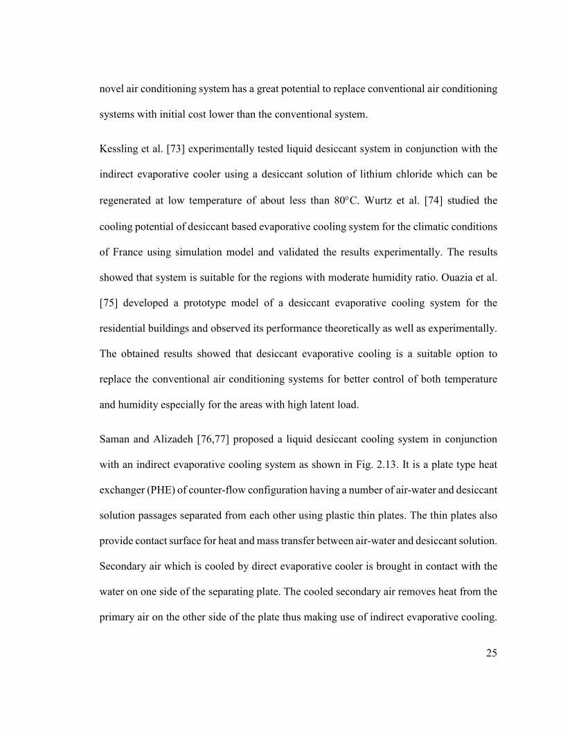
Saman and Alizadeh [76,77] proposed a liquid desiccant cooling system in conjunction
with an indirect evaporative cooling system as shown in Fig. 2.13. It is a plate type heat
exchanger (PHE) of counter-flow configuration having a number of air-water and desiccant
solution passages separated from each other using plastic thin plates. The thin plates also
provide contact surface for heat and mass transfer between air-water and desiccant solution.
Secondary air which is cooled by direct evaporative cooler is brought in contact with the
water on one side of the separating plate. The cooled secondary air removes heat from the
primary air on the other side of the plate thus making use of indirect evaporative cooling.
26
This primary air is dehumidified concurrently using desiccant solution sprayed on cross
flow contact area. The performance of the proposed model was observed theoretically and
then experimentally under climatic conditions of Brisbane, Australia. It was found that the
effectiveness of the evaporative cooler could reach 75% for the exchanger angle (angle
made by the direction of desiccant spray with the horizontal) of 45°.
Figure 2.13: Schematic of compact cross flow type plate heat exchanger [76].

27
Nelson et al. [78] developed and simulated two different models of desiccant evaporative
cooling system working on recirculation and ventilation cycles for the conditions of Miami,
Florida. The results showed that 95% of energy can be obtained from the sun for the
regeneration of desiccant wheel using a collector of 45m2 for the system working on
ventilation cycle. Smith et al. [79] developed and studied the desiccant cooling operating
on ventilation cycle in conjunction with direct evaporative coolers for three different
locations Pittsburgh (Pennsylvania), Macon (Georgia), and Albuquerque (New Mexico).
The obtained results showed that desiccant based evaporative cooling system had good
performance and can meet the cooling load demands for all three locations. The maximum
solar energy fraction of the regeneration energy requirements is for the Pittsburgh (about
75%). Al-Sulaiman et al. [80] analyzed a multistage evaporative cooling system using
liquid desiccant dehumidifier between the stages. The thermal (line heater) as well as
mechanical energy (Reverse Osmosis process) were used for the regeneration of the
desiccant solution. The results showed that the energy consumption was 25% more while
using mechanical source for regeneration as compared to the thermal source to increase the
temperature of desiccant solution by 22°C.
Many researchers have studied the heat and mass transfer of desiccant evaporative cooling
systems applying partial differential equations of heat and mass for individual components
that is desiccant wheels or indirect evaporative coolers without analyzing the performance
of overall system [81, 82]. Radhwan et al. [83] mathematically modeled a solar assisted
liquid desiccant (calcium chloride) evaporative cooling system and observed the system
performance for long term operation under conditions of Jeddah, Saudi Arabia. System

28
thermal ratio (STR), desiccant replacement factor (DRF) and solar utilization factor (SUF)
were defined to observe the system performance for different conditions of weather. The
results showed that system has a good performance for hot and humid climates. Bellemo
et al. [84] numerically studied dew point evaporative cooler, also called as regenerative
indirect evaporative cooler, which is a part of desiccant cooling system and analyzed its
performance for different flow rates of air, inlet air conditions and recirculation fractions.
The results showed that cooling capacity of dew point evaporative cooler was maximized
for recirculation fraction of about 0.3 and supply conditions were mostly affected by the
inlet air humidity ratio. Because of the regenerative arrangement dew point evaporative
cooler did not require secondary air stream as required in indirect evaporative cooler. In
regenerative arrangement, the wet bulb temperature of the inlet air can be achieved [85].
Goldsworthy and White [86] studied a solid desiccant evaporative cooling system design
using an indirect evaporative cooler. It was concluded that the proposed system has a great
potential to save energy and reduce the emission of greenhouse gases. The results also
showed that a high value of electrical coefficient of performance for indirect evaporative
cooler could be achieved with a regeneration temperature of 70°C, ratio of process to
regeneration air flow rate of 0.67, and ratio of secondary to primary air flow rate of 0.3.
Pescod [87] described a cross flow indirect evaporative cooler with a flow of water in the
wet channel opposite to the flow of secondary air. The spacing of channel, protrusion
details, length of the channel, flow velocities and flow rates of water were the key design
parameters used in the study. A thermo economic analysis of direct evaporative cooler
coupled with desiccant dehumidifier was carried by Camargo et al. [88] based on first and

29
second law of thermodynamics. Chen et al. [89] developed a heat and mass transfer model
for the calculation of thermal and hydraulic performance of indirect evaporative cooler.
They concluded that the system had much higher performance when room air was used as
secondary air. Subramanyam et al. [90] studied the effect of different parameters, that is,
air flow rate, speed of wheel etc. on the performance of the solid desiccant wheel for low
humidity conditioning. The optimum wheel speed was found to be 17.5 rpm for better
system performance and moisture removal capacity of the desiccant wheel.
Khoukhi [91] simulated solid desiccant cooling system with direct and indirect evaporative
cooler using measured data sets to observe the system performance under hot and humid
climatic conditions. Figure 2.14 shows the temperatures and humidity at each point of the
cycle for a standard desiccant cooling cycle with precooling and direct evaporative cooler
while Fig. 2.15 shows the results for the desiccant system just with pre-cooling only. The
results showed that for the ambient dry bulb temperature and relative humidity of 36°C and
70%, respectively, the solid desiccant cooling system in conjunction with direct or indirect
evaporative cooler can achieve the acceptable range of temperature and humidity for
human comfort (29°C and 59%). Suryawanshi et al. [92] concluded that, as compared to
conventional systems, two stage evaporative cooler is 4.5 times more efficient but only in
hot and dry climatic conditions. For the hot and humid climatic conditions it can be
combined with desiccant dehumidifiers. Mohammad et al. [93] found from the
experimental results that a direct evaporative cooler can be used effectively in conjunction
with the desiccant dehumidifier to provide the comfort conditions for the climatic
conditions of Kuala Lumpur, Malaysia.

30
Figure 2.14: Schematic diagram of the standard desiccant cooling system with pre-cooling and DEC [91].
Figure 2.15: Schematic diagram of the standard desiccant cooling system with pre-cooling [91].
Jain et al. [94] evaluated the performance of solid desiccant based direct evaporative
coolers operating on different cycles for 16 cities in India. The results showed that system
operating on Dunkle cycle gives the best performance among ventilation, recirculation and
Dunkle cycles. Kim and Jeong [95] investigated the solid desiccant and evaporative
cooling system based on 100% outdoor air to observe the thermal and energy performance
of the system. Both indirect evaporative cooler (IEC) and direct evaporative cooler (DEC)
are utilized in their work. The results showed that, this system could save about 74~77%
of total system operating energy as compared to the conventional systems. Glav [96]

31
introduced staged regeneration for solid desiccant dehumidifier in his patent for better
performance of the system. Worek et al. [97] reported that by using a desiccant of Type
1M which can be regenerated at 165°C and with staged regeneration fraction of 16%, a
ventilation cycle can operate with high performance. A rotary two stage desiccant cooling
system using a composite desiccant material was developed by Ge et al. [98]. The
experimental results showed that high performance of the system can be achieved with
lower regeneration temperature which makes the use of low grade energy feasible.
2.5 Advantages of desiccant-aided evaporative cooling
Some advantages of the desiccant cooling technology in conjunction with the evaporative
cooler are:
• It can be used for hot and humid climates because evaporative cooling alone is not
feasible for such conditions.
• A lot of energy is saved as compared to vapor compression cycle because of no
preheating is required.
• Environment friendly system because of no use of refrigerant which affects the
ozone layer.
• Separate and better control of sensible and latent loads. The desiccant wheel
controlling the latent part and the evaporative cooler controlling the sensible one.
• The overall system has low maintenance cost because it operates at almost
atmospheric conditions.

32
• Low grade energy such as solar, biomass, etc. can be effectively used to drive the
system.
2.6 Major applications of desiccant based evaporative cooling
In some spaces, better control of both temperature and humidity used to be required in
order to avoid the growth of fungi and bacteria which affects the human health. Some of
the main applications of desiccant based evaporative cooling are listed below [99]:
• Supermarkets
• Theatres
• Hospitals
• Hotels
• Office buildings
• Indoor swimming pools
• Pharmaceutical manufacturing plants
2.7 Performance Index
The cooling capacity ()� (sensible load) of an evaporative cooler is given as,
( ). .
i opaaQ V C T Tρ= × × × − (2.2)
The total cooling load (sensible and latent) of the desiccant evaporative cooling system is
given as,
33
. .
1 2( )t aQ V h hρ= × × − (2.3)
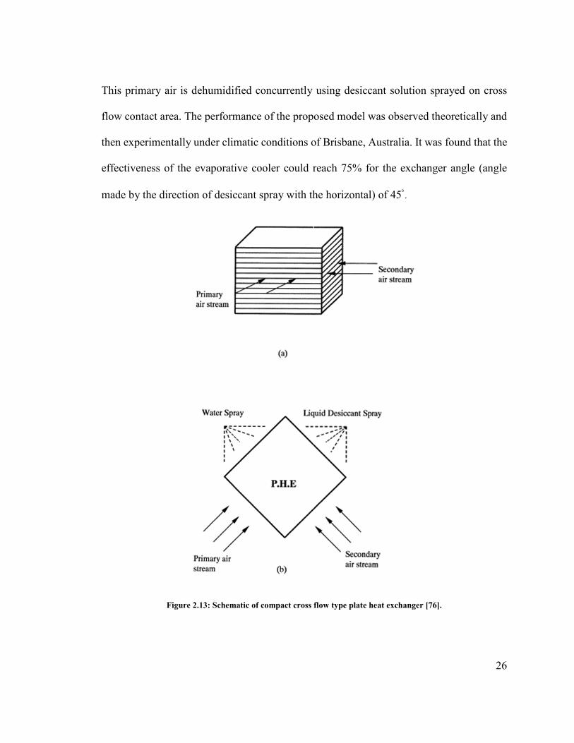
The evaporative cooler effectiveness can be given as,
Effectiveness = 23*4)' *"56"7)*47" 8796 )3(%":"8;)<%545 69$$%&'" *"56"7)*47" 8796 (2.4)
For wet bulb effectiveness, actual temperature drop is the difference between the dry bulb
temperature of inlet process air and the temperature of process air at outlet of the
evaporative cooler. The maximum possible temperature drop can be obtained from the
difference between the dry bulb temperature and wet bulb temperature [42,100]. In dew
point effectiveness the maximum possible achievable temperature drop is obtained from
the difference between dry bulb and dew point temperature of inlet air [101].
i o
i wwet
T TT T
ε −=− (2.5)
i o
i dpdew
T TT T
ε −=− (2.6)
It is to be noted that counter flow indirect evaporative coolers can have a dew point
effectiveness of above 100% because it can cool the air below its dew point temperature.
The Energy Efficiency Ratio (EER) of the evaporative cooler is the ratio between the
cooling produced to the input energy to the cooler.
.
in
QEER
W= (2.7)

34
The direct evaporative cooling systems have temperature effectiveness of about 70–95%
[102]. Stoitchkov and Dimitrov [103] reported the indirect evaporative cooling system
(IEC) are more attractive than the direct evaporative system but IEC has lower cooling
effectiveness (about 40% to 60%). Camargo et al. [104] featured an effectiveness of 70-
80% and 90% for indirect and direct evaporative coolers, respectively.
The wet bulb effectiveness of the evaporative coolers used in the desiccant based
evaporator cooling system, shown in Fig. 2.12, can be evaluated as
3 41
3 3EC
w
T TT T
ε −=− (2.8)
5 6
25 5
ECw
T T
T Tε
−=
− (2.9)
The rate of moisture added by EC1 and EC2 to the process and regeneration air can be
given as
. .
, EC 1 1 4 3( )wm m ω ω= − (2.10)
. .
, EC 2 2 6 5( )wm m ω ω= − (2.11)
2.8 Modified evaporative cooler
Eskra [105] introduced the concept of two stage evaporative cooling for higher efficiency
of the system. In two-stage evaporative cooling both direct and indirect processes are
combined. Both, the schematic diagram and psychometric process of the two-stage

35
evaporative cooler is shown in Fig. 2.16 and Fig. 2.17, respectively. The air is pre-cooled
in the first stage using a heat exchanger by evaporation on the outside. In the second stage,
air from the first stage is cooled and moisture is added to it as passes through the soaked
pads. As air temperature is lowered in the first stage so less moisture is added in the second
stage which in turns leads to better thermal comfort conditions. Two-stage evaporative
cooler uses 100% fresh outside air and as compared to conventional systems it reduces the
energy consumption of about 60 to 75%.
Figure 2.16: The schematic of the two-stage evaporative cooler [92].
36
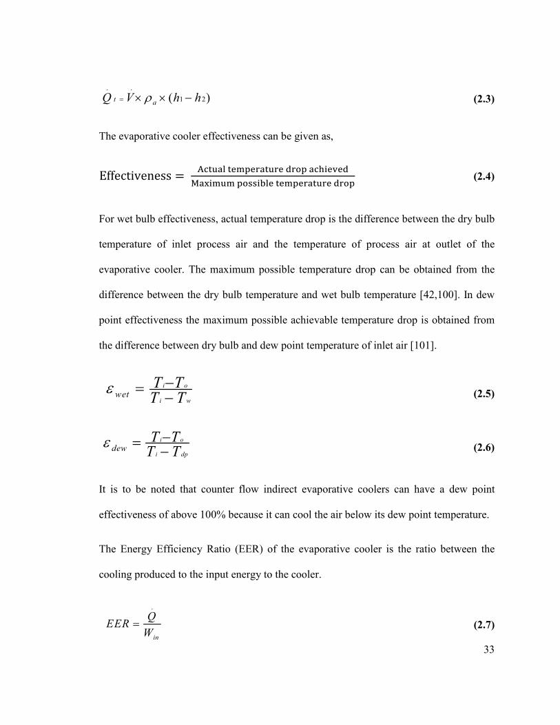
Figure 2.17: The psychrometric process representation of the two-stage evaporative cooler.
Kulkarni and Rajput [106] theoretically analyzed the performance of two stage evaporative
cooler for the climatic conditions of Bhopal, India. The results showed that, for the air flow
rate of primary air 0.3 to 1.25 kgs-1 the effectiveness of indirect evaporative cooler varied
from 0.95 to 0.82. For the two stages combined operation, saturation efficiency varied
between 121% and 107% and cooling load capacity from 5.06 to 20.50 kW as compared
to saturation efficiency of 89% to 64% and cooling capacity of 3.18 to 16.6 kW for single
stage direct evaporative cooling. The temperature obtained at the outlet of the cooler lies
between 22.5°C and 24.6°C for ambient dry bulb temperature and relative humidity of
39.9°C and 32.8%, respectively. Watt [107] first analyzed different types of evaporative
cooling systems. Watt also discussed about the history of different types (direct, indirect,
two stage) of evaporative coolers and their operating principles. Maclaine-cross and Banks
[108] developed a model for wet surface heat exchangers which can be used to predict the
Dry bulb temperature (oC)
Hum
idity
rat
io (
kg/k
g of
dry
air
)
Entering air conditions
Supply air conditions
Indirect evaporative cooling
37
performance of different types of evaporative coolers. The results showed that by using
such a heat exchanger, the proposed regenerative evaporative cooling unit has excellent
overall performance. Yellott and Gamero [109] studied different types of indirect
evaporative coolers by introducing psychrometric analysis related to indirect evaporative
coolers. Evaporative coolers can be utilized in almost all climatic conditions. The wet-bulb
temperature of the entering air stream and secondary air stream limits the use of direct and
indirect evaporative cooler respectively.
Eskra [110] studied a two stage indirect direct evaporative cooling system. The results
showed that, for the ambient wet bulb temperature below 25oC, the system would produce
cooling of 5 to 15 times per Watt of energy input. In order to maximize the moisture
transfer, some modern evaporative coolers have been introduced which combines the high
performance media with low velocity air as shown in Fig. 2.18. These evaporative coolers
with well design and thickness of media of about 10 to 12 inches (25.4 to 30.4cm) or more
can have an effectiveness of around 93% as compared to maximum effectiveness of 80%
of typical systems. In modified evaporative coolers, the air can be cooled to the temperature
lower than the temperature achieved by indirect or direct evaporative cooler without
disturbing the humidity of the air. Theoretically, the dew point temperature of the inlet
process air can be achieved using modified evaporative cooler. But the modified
evaporative cooler requires more fan power as compared to indirect or direct evaporative
cooler because of splitting of air. It consists of a plate type sensible heat exchanger and a
direct evaporative cooler [111].

38
Figure 2.18: Modern Evaporative Cooling Media (Source: Munter).
Bisoniya et al. [112] presented a model for modified indirect evaporative cooler and
compared results of theoretical and experimental thermal analysis. The schematic is shown
in Fig. 2.19 which is a cross flow heat exchanger with one fluid mixed and other unmixed.
The results showed that theoretical model presented can be used to predict the performance
of the modified indirect evaporative cooler. The results also showed that, the evaporative
cooler had best performance in hot and dry climatic conditions. Bruno [39] observed the
performance of indirect evaporative cooler installed at Roxby Downs, Australia for cooling
a residential building. The schematic of the system is shown in Fig. 2.20 in which part of
the cooled air is returned along the wet channel to achieve the dew point temperature of
the incoming air. The obtained results showed the cooling power of 10.8 kW over the
average day can be achieved with this indirect evaporative cooler for dry and hot
conditions. The average value of outlet temperature of the system achieved can reach
14.9oC at an ambient temperature of 34.7oC. The system has average wet bulb and dew
point effectiveness of 124% and 74%, respectively.

39
Figure 2.19: Schematic diagram of modified indirect evaporative cooler [112].
Figure 2.20: Schematic of indirect evaporative cooler to achieve dew point temperature of the incoming air [39].
Room(3) Cross flow heat
exchanger
Water tank
Supply fan
Outdoor air
(1)
(2)
(4)
Sensible heat
Latent heat
Recirculation of exhaust
humid air
Exhaust to atmosphere Exhaust air
(5)
Exhaust fan
(3)Return air
Water pump

40
2.9 Developments in evaporative cooling research
Because of the increasing interest and significant potential of the technology, various
methods of evaporative cooling have been investigated by many researchers. Recently
evaporative based air conditioning units are not commonly used as small household units.
Al-Sulaiman [113] evaluated the local fibres performance in evaporative cooling using
wetted pads of date palm fibres, jute and Luffa in the evaporative cooler. The obtained
results showed that jute has highest efficiency of 62.2% while Luffa, commercial pads and
date fibres has 55.1%, 49.9% and 38.9%, respectively. Alonso et al. [114] developed a
universal heat and mass transfer model for design and optimization of indirect evaporative
coolers. The results of detailed numerical study showed that transfer of heat from gas-liquid
interface in determined by the latent heat transfer.
The 50% of the building heating load comes from the roof. Al-Nimr et al. [115] observed
the performance of evaporative cooler by using different techniques to reduce the roof
heating load like painting the roof with white, by insulating the roof from inside etc. the
results showed an increase in the performance of the evaporative cooler. Ibrahim et al.
[116] studied porous ceramic evaporators for building cooling applications using direct as
well as indirect evaporative coolers. The results showed that ceramic materials with high
porosity have better performance. Jain and Hindoliya [117] tested a regenerative
evaporative cooler. It was developed by adding a water to air heat exchanger in the path of
outgoing air stream from the direct evaporative cooler. It was found that COP and
efficiency of the unit increases 20-25% because of the higher cooling capacity of
regenerative evaporative cooler. The results of different studies showed that indirect

41
evaporative coolers are mostly preferred over the direct evaporative coolers especially
when high humidity is not desired [99]. Different parametric and comparative studies have
also been carried out by many researchers to analyze and compare the performance of
evaporative coolers [118-120]. Different studies related to evaporative cooling systems has
been summarized in Table 2.2. The evaporative cooling technology is under process of
development. Some important steps needs to be taken for development of this technology
have been summarized in Table 2.3 [121].
Table 2.2: Summary of different studies related to evaporative cooling systems.
Study System description Method System performance/Outcomes
Zhao et al. [44] Counter-flow indirect evaporative cooler (IEC) made from plate fin
heat exchanger
Simulation Wet bulb effectiveness (54-130%)
Dew point effectiveness (36-82%)
Halliday et al. [48] Solid desiccant based evaporative cooling system driven by solar
energy under climatic conditions of UK
Analytical About 72% of the thermal energy can be provided by
solar energy for New Mexico
Enteria et al. [50] Solid desiccant cooling system in conjunction with evaporative
cooler
Experiment Solar energy can be efficiently used for desiccant cooling
system to minimize the use of electric energy
Archibald [55] Solid desiccant based evaporative cooling
Experiment The system can handle about 87% of total building cooling
and heating load
Haddad et al. [67] Desiccant-evaporative cooling system
Experiment
and
simulation
The system offers a promising alternative to vapor compression system
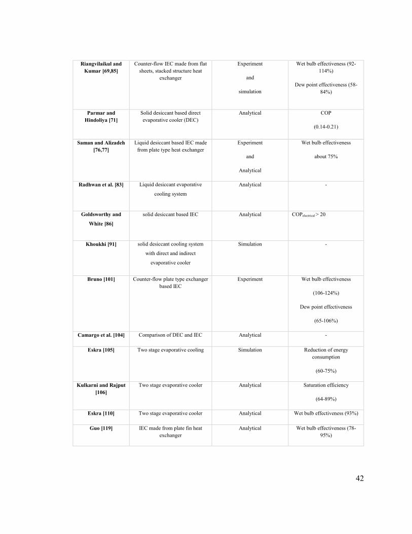
42
Riangvilaikul and Kumar [69,85]
Counter-flow IEC made from flat sheets, stacked structure heat
exchanger
Experiment
and
simulation
Wet bulb effectiveness (92-114%)
Dew point effectiveness (58-84%)
Parmar and Hindoliya [71]
Solid desiccant based direct evaporative cooler (DEC)
Analytical COP
(0.14-0.21)
Saman and Alizadeh [76,77]
Liquid desiccant based IEC made from plate type heat exchanger
Experiment
and
Analytical
Wet bulb effectiveness
about 75%
Radhwan et al. [83] Liquid desiccant evaporative
cooling system
Analytical -
Goldsworthy and
White [86]
solid desiccant based IEC Analytical COPelectrical > 20
Khoukhi [91] solid desiccant cooling system
with direct and indirect
evaporative cooler
Simulation -
Bruno [101] Counter-flow plate type exchanger based IEC
Experiment Wet bulb effectiveness
(106-124%)
Dew point effectiveness
(65-106%)
Camargo et al. [104] Comparison of DEC and IEC Analytical -
Eskra [105] Two stage evaporative cooling Simulation Reduction of energy consumption
(60-75%)
Kulkarni and Rajput [106]
Two stage evaporative cooler Analytical Saturation efficiency
(64-89%)
Eskra [110] Two stage evaporative cooler Analytical Wet bulb effectiveness (93%)
Guo [119] IEC made from plate fin heat exchanger
Analytical Wet bulb effectiveness (78-95%)

43
Table 2.3: Needed R & D for desiccant based evaporative cooling technology [121].
Topic Actions to be taken
Technology development • Development of different tools and software for modeling.
• Collaborative partnership between desiccant based
evaporative cooling manufacturers, the HVAC industry, and
researchers need to be established.
Field testing and performance
mapping
• Additional field trials to be conducted.
• Performance maps development for different climatic
conditions and operating parameters.
Tools and software • Simulation software tools should incorporate evaporative
cooling technologies.
2.10 Conclusions
The desiccant based evaporative cooling system is relatively a new technology and is a
good alternative for conventional mechanical vapor compression air conditioning system
especially in hot and humid climatic conditions but less familiar as compared to
conventional cooling system. In order to familiarize the desiccant based evaporative
cooling systems, designed activities such as workshop, seminars, onsite visit, lectures,
exhibition, and publicizing the research results in dedicated ways are required.
Standardizations, legislations, public awareness, and regulations are the main issues needs
to be focused for such cooling systems. In this paper, the work done by different researchers
on desiccant based evaporative coolers has been summarized. The main observations are
summarized as follows:

44
• The conventional air conditioning systems are not suitable for hot and humid
climatic conditions because of its high sensible heat ratio. These systems can
provides the comfort conditions only when sensible heat ratio is greater than 0.75.
• The evaporative cooling system is a good alternative to conventional air
conditioning systems which not only saves energy but also is environmental
friendly.
• In the indirect evaporative system the process air stream not directly interact with
the cooling fluid stream and is only cooled sensibly while in direct evaporative
system moisture is also added to the cooled air stream because process air streams
comes in direct contact with the cooling water.
• The evaporative cooling system becomes less efficient in hot and humid climatic
conditions. Under these conditions, evaporative cooling system can be operated in
conjunction with desiccant dehumidifier with high efficiency.
• The heat and mass transfer is less affected by the thermal properties (thermal
conductivity and porosity) of the packing material used for heat and mass transfer
in an indirect evaporative cooler while main factors to be concerned are cost, shape
formation, holding ability, durability, compatibility with water-proof coating.
• In modified evaporative cooler, the air can be cooled to the temperature lower than
the temperature achieved by indirect or direct evaporative cooler without disturbing
the humidity of the air.
• Low grade thermal energy such as solar, biomass etc. can be effectively used for
the continuous operation of the desiccant based evaporative cooling system.
45
This technology is relatively immature in terms of production scale as compared to the
conventional cooling systems. Furthermore, the environmental, economic, and social
impacts which are related to this technology must be investigated and a clear understanding
and knowledge of these issues needs to be addressed.
The desiccant based evaporative cooling technology can first be targeted for commercial
buildings rather than residential buildings because of high energy and financial payback in
hot and humid climatic areas. The combination of recent advances in desiccant materials
and the evaporative cooling technology must be used to design cheaper, reliable and
compact cooling systems. Finally, the technology should be converted into products which
are market attractive.
46
3 CHAPTER 3
LITERATURE REVIEW OF LIQUID DESICCANT
MATERIALS AND DEHUMIDIFIER
3.1 Introduction
3 It is important to decrease the energy cost of heating, ventilating and air conditioning
(HVAC) systems without compromising indoor air quality and comfort conditions due to
the rising cost of fossil fuels and other environmental concerns. Liquid desiccant cooling
systems are one of the alternatives in this regard which is not only environmental friendly
(no use of any refrigerant which deplete ozone layer) but at the same time make a good use
of alternative sources of energy like, solar, biomass etc. This chapter presents
different commercially available liquid desiccants and their composites which combines
the properties of two or more desiccant materials for better performance. A good desiccant
should have better moisture absorption capability and lower temperature of regeneration.
This paper also includes the different configurations of liquid desiccant dehumidifiers and
their advantages as well as drawbacks. Some new configurations of liquid desiccant
dehumidifiers have been introduced which greatly improves the system overall
performance. Moreover, a summary of the performance parameters has been made to
analyze the system performance. This review is meaningful for the research and technical
development process of liquid desiccant technology.

47
3.2 Liquid desiccant cooling
The control of indoor air temperature and relative humidity for the human comfort divides
the building’s cooling load into sensible and latent load, respectively. The conventional
compressor based air conditioners can control the building sensible load effectively but
these systems are less efficient to take the building latent loads. In these systems a lot of
energy is wasted to overcool the air below its dew point to remove the moisture from the
air by the process of condensation and then again reheating the air to the required supply
temperature. Secondly, this process of overcooling provides the conditions for the growth
of molds and bacteria because of surface wetting which can cause health issues by affecting
indoor air quality [122]. Some alternative is required to avoid this wastage of energy
because of overcooling and reheating [123]. The latent load is more dominant in hot and
humid climates and there is a need for air conditioning system to effectively handle the
latent loads [124]. The liquid desiccant cooling units seem to be a feasible and cost effective
alternative to provide the human comfort conditions in hot and humid climates. It absorbs
and desorbs the moisture from and to the air during absorption and regeneration processes,
respectively [125].
In the liquid desiccant cooling system simultaneous transfer of heat and mass occurs. The
latent load is controlled by the transfer of mass (moisture) from the humid air to the liquid
desiccant surface. For the process of mass transfer, three theories namely penetration, film
and surface renewable are mostly used. The film theory is mostly used for the mass transfer
phenomenon. It was proposed by Nernset [126] by assuming the presence of resistance to
48
mass transfer within small region close to interference of two streams. Two film theory
was developed by Whiteman [127].
The liquid desiccant systems are more energy efficient and provides an effective control of
indoor air humidity [128]. Most of the liquid desiccant units are direct contact type in which
air comes in direct contact with the desiccant solution [129]. The problem of carryover of
desiccant solution is a major problem in these direct contact type units. The problem of
carryover will affect the indoor air quality and will also increase the cost of maintenance
because of corrosion [130]. Abdel-Salam et al. [131] proposed a new type of liquid air
membrane energy exchanger as the dehumidifier to avoid the problem of desiccant solution
carryover. The results under fully developed conditions give system coefficient of
performance of 0.6 and humidifier sensible heat ratio of 0.3 - 0.5. Bichowsky [132] utilized
the lithium chloride (LiCl) solutions for the purpose of drying the air. A field test was
conducted for residential scale system but at that time this was not introduced to the market.
3.3 Performance parameters
The commonly used performance parameters which are utilized to investigate the
performance of the system are listed in Table 3.1.

49
Table 3.1: Performance parameters used for liquid desiccant cooling systems.
Moisture removal rate (kg/s)
It represents the removed water vapor from the humid process air by the liquid desiccant cooling unit.
Humidity or moisture effectiveness
It is ratio between actual changes in humidity ratio of the air across the dehumidifier to the maximum possible change in humidity ratio of air.
Enthalpy effectiveness It is ratio between actual changes in enthalpy of the air across the dehumidifier to the maximum possible change in enthalpy of air.
Sensible heat ratio It is the ratio between the sensible energy to the total energy removed from the process air by the dehumidifier.
Cooling capacity
(kW)
It is the overall cooling effect produced by the system. It is a difference between the enthalpies of inlet and process air.
Coefficient of performance
It represents the ratio between the cooling capacity to the total consumed energy (electrical and thermal) by the liquid desiccant cooling system.
Electrical coefficient of performance
It is a ratio between the system cooling capacity to the consumed electrical energy by the liquid desiccant cooling system.
Thermal coefficient of performance
It is a ratio between the unit cooling capacity to the consumed thermal energy in the liquid desiccant cooling system.
3.4 Advantages of using liquid desiccants
To control the latent load for air conditioning solid as well as liquid desiccant systems can
be used in different configurations as shown in Fig. 3.1 [133] . The liquid desiccant system
has following advantages:
• Lower drop in the pressure of process air stream.
• Low grade energy sources can be utilized for regeneration purposes because liquid
desiccant systems have lower regeneration temperature (about 65 - 80°C) with good
dehumidification performance.

50
• For large capacity cooling system multiple liquid desiccant cooling systems can be
connected by pumping the liquid desiccant in between them.
• The dehumidification and regeneration of liquid desiccant simultaneously, is
eliminated because weak liquid desiccant can be stored until regeneration heat is not
available.
• The entire weak desiccant solution need not to be circulated for regeneration. A small
amount of desiccant solution can be over-concentrated and mixed with weak solution.
• It is highly beneficial factor that liquid desiccants have the ability to filter different
bacteria, microbial contamination, viruses, and molds which can affect the human
health from process air stream.
The difference of surface vapor pressure between liquid desiccant layer and humid air act
as the driving force for mass/moisture transfer; therefore, in order to increase the
regeneration efficiency of the system, the surface vapor pressure of desiccant must be
increased by preheating the desiccant solution leaving the dehumidification unit. Similarly,
in order to achieve higher efficiency for the dehumidification process, pre-cooling of liquid
desiccant at the inlet is needed to lower its surface vapor pressure. Heat exchangers are
utilized in between the two streams to effectively preheat the weak solution leaving the
dehumidification unit and to pre-cool the entering strong solution. In order to avoid the
crystallization, an auxiliary heater can be equipped with the storage tank. The normal
operation of the system can be affected by this auxiliary heater because clogging in the
pipe [134]. Jiang et al. [135] compared liquid desiccant cooling system and conventional
air conditioning systems which are listed in Table 3.2.
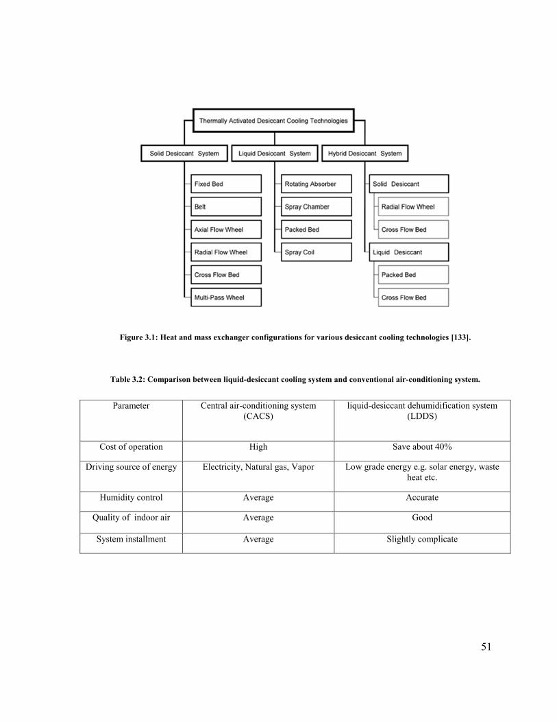
51
Figure 3.1: Heat and mass exchanger configurations for various desiccant cooling technologies [133].
Table 3.2: Comparison between liquid-desiccant cooling system and conventional air-conditioning system.
Parameter Central air-conditioning system (CACS)
liquid-desiccant dehumidification system (LDDS)
Cost of operation High Save about 40%
Driving source of energy Electricity, Natural gas, Vapor Low grade energy e.g. solar energy, waste heat etc.
Humidity control Average Accurate
Quality of indoor air Average Good
System installment Average Slightly complicate

52
3.5 Liquid desiccant materials
A desiccant material attracts the water vapor towards itself and these materials are used
where air of low dew point is needed. The strength of a liquid desiccant can be measured
by its equilibrium vapor pressure, which is water vapor pressure that is in equilibrium with
liquid desiccant material. The vapor pressure exponentially increases with the temperature
of the water or desiccant and also increases as the water is absorbed by the desiccant, that
is, equilibrium vapor pressure will be higher for a dilute liquid desiccant than a
concentrated one [136].
Some other parameters which indicate desiccant materials performance are:
• Energy storage density
• Temperature for regeneration
• Boiling point elevation (BPE)
• Availability
• Cost
A good desiccant should have the following properties:
• Large saturation absorption capacity
• Low regeneration temperature
• Low Viscosity
• High heat transfer
• Non-volatile
53
• Non-corrosive
• Odorless
• Non-toxic
• Non-flammable
• Stable
• Inexpensive
Surface tension plays important role in static hold up and surface wetting of heat and mass
exchanger of liquid desiccant system.
Commonly used liquid desiccants in the industrial dehumidifiers are glycols and solutions
of halide salts which include lithium chloride (LiCl), lithium bromide (LiBr), calcium
chloride (CaCl2), triethylene glycol and mixture of salts etc. The selection of a desiccant
material will have a direct effect on the desiccant dehumidifier design.
The earliest used liquid desiccant is triethylene glycol but its use is limited because it has
high viscosity which causes system operation unstable because of liquid residence. They
are low toxic and compatible with most of the metals but all glycols are volatile because
of very low surface vapor pressure, some of it evaporates with air into the conditioned
space which sometimes makes them unacceptable for air conditioning applications [137].
The dew point temperature of air by using a solution of triethylene glycol (96%) and water
(4%) can be achieved with LiCl solution concentration of 42% by weight. But at
equilibrium point, the molar concentration of the glycol in the air will be in the order of

54
1% that of the water vapor which means annual loss of triethylene glycol in air conditioning
applications will be very high.
Salts of Halides such as LiCl and LiBr can dry air to 15% and 6% relative humidity,
respectively but these salts are naturally corrosive. LiCl is a very good desiccant because
at ambient conditions it will not vaporize and it has low viscosity which reduces the
required pumping power but its mixing with the process air must be avoided. Halide salts
are relatively expensive in nature [138].
Another alternate of low corrosive and non-volatile desiccants are salts of weak organic
acids such as, potassium or sodium formate and acetate. Potassium acetate is less expensive
it can dry air up to 25% relative humidity but its viscosity becomes very high. At a
temperature of 27oC and concentration of 70% by weight of potassium acetate has a
viscosity of about 28 cp (0.028 Pa/s) but LiCL solution concentration of 43.l % by weight
at the same temperature, has almost half of that viscosity.
Weak organic acid salts like sodium formate or potassium and acetate are less corrosive
and less volatile as compared to halide salt. Formate salts are less viscous than acetate salts
at concentrations with equivalent equilibrium relative humidity. Although potassium
formate is a relatively weaker desiccant as compared to LiBr or LiCl but it has the ability
to dry the air below 30% relative humidity and it can be a good alternative desiccant for
many applications.
Zuber et al. [139] and Ahmed et al. [140] provided thermodynamic properties of single
desiccants. Among different desiccants LiCl has lowest vapor pressure and found to be
55
most stable but this desiccant is very expensive as compared to other liquid desiccants.
Calcium chloride (CaCl2) is readily available and the cheapest desiccant. But its stability
depends upon conditions of inlet air and concentration of desiccant in the solution which
makes its use limited. Morillon et al. [141] measured the water vapor pressure above salt
solutions such as, CaCl2, LiCl, and LiBr.
Sun et al. [142] thermodynamically analyzed different liquid desiccants and calculated the
vapor pressure of these desiccants. Thermodynamic properties of LiBr aqueous solution
are provided by McNeely [143]. While an equation is developed by Kaita [144] for
thermodynamic properties of aqueous LiBr solution at high temperatures. This equation is
valid for temperatures of 40–210oC and concentration of 40–65% by weight. de Lucas et
al. [145] provided the properties of the water, LiBr and potassium acetate mixture and also
for the mixture of water, LiBr and sodium lactate. Park et al. [146] made an attempt by
adding four 8-C alcohol additives (2-octanol, n-octanol and 3-octanol ) to liquid desiccant
to lower its surface vapor pressure.
Ertas et al [147] presented the properties of LiCl and CaCl2 mixture at a temperature range
of 26.5 to 65.4oC with a purity of 99.3% and 90%, respectively. The results of investigation
showed that viscosity of the mixture is low and it is highly soluble. As compared to pure
CaCl2 solution the mixture has lower vapor pressure.
The term brine bulb temperature is used to represent the temperature which is achieved at
the interface of air and liquid desiccant. This temperature depends on temperature and
humidity of air as well as concentration of desiccant. A solution of air and lithium chloride

56
(43%) at a dry and wet bulb temperature of 30.0 and 25.6°C, respectively will have a brine
bulb temperature of 47.8°C. [136].
3.6 Composite desiccant materials
A number of composite desiccant materials have been developed in the past few years to
improve their performance. Aristov et al. [148] have developed composite desiccant
materials compromising of silica gel/SiO2 and inorganic salt (CaCl2, LiBr, SrCl2, and
NaSO4). The results showed that these composite materials have lower desorption
temperature. About 80% of adsorbed water could be desorbed from these composite
desiccant materials at a temperature between 80 and 90oC.
Jia et al. [149] have developed composite desiccant of silica gel impregnated with CaCl2
and LiCl. After experimental results for regeneration temperature of 120oC under humid
and hot climates, moisture removal capacity of silica gel-calcium chloride wheel was found
to be 20% better than the conventional silica-gel wheel. Adsorption capacity was improved
by 67–145% by using composite of silica gel-LiCl instead of traditional silica gel and 13X
molecular sieve under temperatures of 25oC, 35oC and 40oC. The adsorption capacity of
different composite materials are shown in Fig. 3.2 [150].
Liu and Wang [151] developed a composite material compromising of macro-porous silica
gel and CaCl2 (SiO2.x-xH2O.yCaCl2). They studied the impact of porous structure. The
adsorption capacity for this composite at intake conditions of 25oC and 40% relative
humidity (RH) was found to be 0.4 g of water/g of dry adsorbent, which was 5.7, 2.1, 1.9,
6.8 times more than that of macro-porous silica gel, micro porous silica gel, synthetic

57
zeolite 13X and activated carbon, respectively. Moreover, this desiccant material has low
regeneration temperature of about 60–80oC.
(a) silica-gel (25oC); (b) silica gel-Lithium chloride (25oC); (c) sepiolite (23oC); (d) sepiolite-carbont (steam activated) (23oC); (e) sepiolite-carbon (chemically activated with KOH) (23oC); (f) CaCl2–SiO2 sol–
gel (25oC); (g) CaCl2-MCM-41 (20oC); (h) silica gel-LiBr at 20oC.
Figure 3.2: Different desiccant materials isotherms for water adsorption [150].
Gonzalez et al. [152] introduced a new desiccant which is a combination of sepiolite and
activated carbon or sepiolite and CaCl2. This new desiccant combines the fibrous and
hydrophilic nature of sepiolite and hydrophobic nature of activated carbon. The
combination of these properties makes sepiolite applicable for different applications.
Adsorption capacity of sepiolite is enhanced by using a composite of sepiolite- CaCl2.
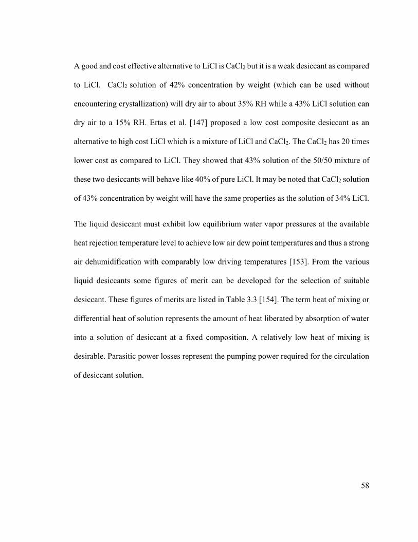
58
A good and cost effective alternative to LiCl is CaCl2 but it is a weak desiccant as compared
to LiCl. CaCl2 solution of 42% concentration by weight (which can be used without
encountering crystallization) will dry air to about 35% RH while a 43% LiCl solution can
dry air to a 15% RH. Ertas et al. [147] proposed a low cost composite desiccant as an
alternative to high cost LiCl which is a mixture of LiCl and CaCl2. The CaCl2 has 20 times
lower cost as compared to LiCl. They showed that 43% solution of the 50/50 mixture of
these two desiccants will behave like 40% of pure LiCl. It may be noted that CaCl2 solution
of 43% concentration by weight will have the same properties as the solution of 34% LiCl.
The liquid desiccant must exhibit low equilibrium water vapor pressures at the available
heat rejection temperature level to achieve low air dew point temperatures and thus a strong
air dehumidification with comparably low driving temperatures [153]. From the various
liquid desiccants some figures of merit can be developed for the selection of suitable
desiccant. These figures of merits are listed in Table 3.3 [154]. The term heat of mixing or
differential heat of solution represents the amount of heat liberated by absorption of water
into a solution of desiccant at a fixed composition. A relatively low heat of mixing is
desirable. Parasitic power losses represent the pumping power required for the circulation
of desiccant solution.
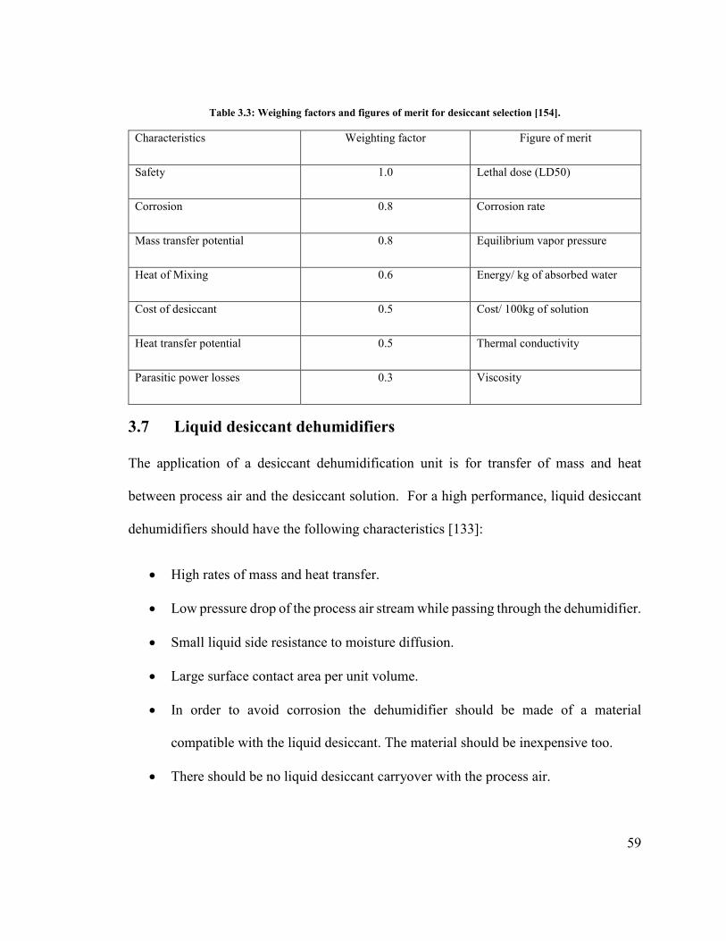
59
Table 3.3: Weighing factors and figures of merit for desiccant selection [154].
Characteristics Weighting factor Figure of merit
Safety 1.0 Lethal dose (LD50)
Corrosion 0.8 Corrosion rate
Mass transfer potential 0.8 Equilibrium vapor pressure
Heat of Mixing 0.6 Energy/ kg of absorbed water
Cost of desiccant 0.5 Cost/ 100kg of solution
Heat transfer potential 0.5 Thermal conductivity
Parasitic power losses 0.3 Viscosity
3.7 Liquid desiccant dehumidifiers
The application of a desiccant dehumidification unit is for transfer of mass and heat
between process air and the desiccant solution. For a high performance, liquid desiccant
dehumidifiers should have the following characteristics [133]:
• High rates of mass and heat transfer.
• Low pressure drop of the process air stream while passing through the dehumidifier.
• Small liquid side resistance to moisture diffusion.
• Large surface contact area per unit volume.
• In order to avoid corrosion the dehumidifier should be made of a material
compatible with the liquid desiccant. The material should be inexpensive too.
• There should be no liquid desiccant carryover with the process air.
60
Liquid desiccant dehumidifiers are classified as adiabatic and internally cooled [155]. The
air directly contact with the desiccant solution in the adiabatic dehumidifiers while in
internally cooled dehumidifiers apart from the contact between two streams, desiccant
solution is cooled down using some cooling medium to increase the system performance.
3.8 Adiabatic dehumidifiers
One of the adiabatic dehumidifiers namely packed bed dehumidifier is the main focus of
most of the researchers. Fumo and Goswami [156] modeled a packed bed dehumidifier for
heat and mass transfer using packing of polypropylene having a volumetric surface area of
210 m2/m3 and experimentally measured its performance with LiCl solution. They
concluded that because of the high surface tension, solution of LiCl did not wet the packing
uniformly. An empirical formula for estimation of fraction of bed wetted surface area was
developed and the performance results of the theoretical model were found in good
agreement with the measured results.
Khoukhi et al [157] experimentally studied the twin rotor desiccant cooling system and
Enteria et al. [158] made a parametric investigation for a modeled twin rotor desiccant
cooling. Enteria et al. [159] made a comprehensive investigation of different thermally
activated desiccant cooling systems and experimentally showed the system dependence
upon climatic conditions and different components performance.
Liu et al. [160] used structured packing with a solution of LiCl for estimation of a cross-
flow desiccant dehumidifier performance. They presented the experimental results in term
of rate of moisture removal and the dehumidifier performance for various values of

61
desiccant flow rates, air flow rates, desiccant and air inlet temperature, desiccant inlet
concentration, and specific humidity of inlet air.
Liu et al. [161] and Liu and Jiang [162] presented an analytical solution for the coupled
heat and mass transfer for a packed-bed system by using the assumptions of minimal
change in desiccant concentration and Lewis number of one. The results of analytical
solutions are closely in agreement with exact numerical solutions and with experimental
data.
Jain and Bansal [163] used empirical relations to predict the performance of packed bed
dehumidifiers compromising of three different liquid desiccant materials (CaCl2, LiCl, and
triethylene glycol). It was found that, the value of dehumidifier effectiveness varies from
10% to 50% or more. The results also showed that, more comprehensive empirical models
are required for better estimation of liquid desiccant dehumidifier performance. The
performance of liquid desiccant dehumidifier can be improved by using a liquid-to-liquid
heat exchanger between the absorber and regenerator as shown in Fig. 3.3.
Katejaneken et al. [164] experimentally studied a liquid desiccant (LiCl) ventilation
preconditioning system. The results showed that system can reduce the relative humidity
by about 11% while the temperature remains almost equal to the ambient air temperature.
It has also been found that evaporation rate remains always greater than the absorbed
moisture by the liquid dehumidifier which makes the system well feasible for continuous
operation.
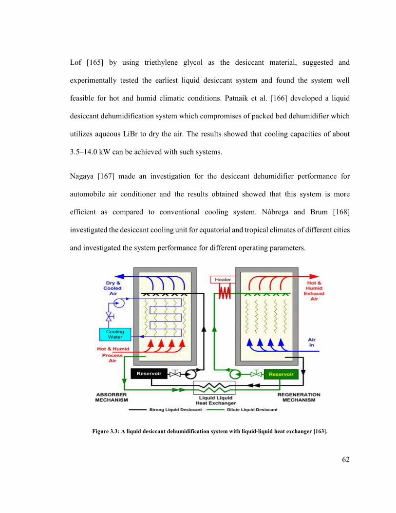
62
Lof [165] by using triethylene glycol as the desiccant material, suggested and
experimentally tested the earliest liquid desiccant system and found the system well
feasible for hot and humid climatic conditions. Patnaik et al. [166] developed a liquid
desiccant dehumidification system which compromises of packed bed dehumidifier which
utilizes aqueous LiBr to dry the air. The results showed that cooling capacities of about
3.5–14.0 kW can be achieved with such systems.
Nagaya [167] made an investigation for the desiccant dehumidifier performance for
automobile air conditioner and the results obtained showed that this system is more
efficient as compared to conventional cooling system. Nóbrega and Brum [168]
investigated the desiccant cooling unit for equatorial and tropical climates of different cities
and investigated the system performance for different operating parameters.
Figure 3.3: A liquid desiccant dehumidification system with liquid-liquid heat exchanger [163].

63
Babakhani [169] developed an analytical solution for simultaneous transfer of heat and
mass in an adiabatic liquid desiccant dehumidifier. The results showed that, a better
prediction of dehumidifier performance can be made by using Lewis number (Le) of 1.1
instead of 1. Similarly, Diaz [170] developed a transient heat and mass transfer model for
a liquid desiccant dehumidifier. The liquid desiccant falls down the walls of dehumidifier
as a thin film. The transient distribution of water vapor and instantaneous average
Sherwood and Nusselt numbers along desiccant-air interface were studied.
Seenivasan et al. [171] investigated the effect of different parameters like desiccant
concentration, desiccant solution temperature, desiccant and air flow rates, and relative
humidity on the effectiveness of liquid desiccant dehumidifier using CaCl2 as the desiccant
material. The optimum values of these parameters were found for high effectiveness of
dehumidifier under the following operating conditions: desiccant temperature 25oC,
concentration 40%, desiccant flow rate 2.25 kg/m2.s, air flow rate 1 kg/m2.s, and RH 85%.
Gommed et al. [172] experimentally measured the performance of packed-bed heat and
mass exchangers using LiCl solution. The copper and polypropylene tubes were used as
contact surfaces in the dehumidifier. The results showed that the copper tubes are more
active to corrosion while in contact with the desiccant solution and on the other hand
wetting is much difficult while using polypropylene tubes. Then the researchers employed
adiabatic packed beds of 285 m2/ m3. The results showed that dripping of LiCl solution
over the packing with suitable drop size to avoid carryover of the desiccant is better than
spraying.

64
Gommed and Grossman [173] made a field test of 16 kW capacity liquid desiccant cooling
system using LiCl solution flowing through the dehumidifier to absorb moisture from the
air. The results showed the system can achieve the coefficient of performance of 0.8.
Chen et al. [174] used four cross flow packed bed dehumidifiers with 42-48% (by weight)
LiBr solution to conduct a field test for liquid desiccant cooling system. The air flows in
series through all the four beds. The flow of air and the desiccant was in counter flow so
that the air can flow in direction of increasing desiccant concentration through the bed. Hot
water at about 69°C and 73°C was used as regeneration sources for the desiccant. The
obtained results showed that the unit had an average coefficient of performance of 1.5.
Kumar [175] developed new cycles for the improvement of the overall system performance
and experimentally studied the influence of different parameters on dehumidifier and
regenerator individual performance. To avoid the desiccant carry over with the air, mist
eliminators (droplet filters) are utilized. These mist eliminators can decrease carryover of
desiccant to parts per billion of process air flow, but air side pressure drop is increased due
to these eliminators and more maintenance is required.
Saman and Alizadeh [176] tested a liquid desiccant air conditioner with evaporative cooler
by using a plastic plates of 0.2 mm thickness and of 600 m2 as contact surface area inside
the dehumidifier. A solution of 40% CaCl2 was used as the desiccant which was sprayed
on the plates. For the value of maximum process air flow, the mass flow rates ratio of
desiccant to air was 0.1. The results showed that with 0.3 kg/s of process air flow rate,
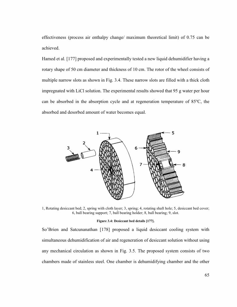
65
effectiveness (process air enthalpy change/ maximum theoretical limit) of 0.75 can be
achieved.
Hamed et al. [177] proposed and experimentally tested a new liquid dehumidifier having a
rotary shape of 50 cm diameter and thickness of 10 cm. The rotor of the wheel consists of
multiple narrow slots as shown in Fig. 3.4. These narrow slots are filled with a thick cloth
impregnated with LiCl solution. The experimental results showed that 95 g water per hour
can be absorbed in the absorption cycle and at regeneration temperature of 85oC, the
absorbed and desorbed amount of water becomes equal.
1, Rotating desiccant bed; 2, spring with cloth layer; 3, spring; 4, rotating shaft hole; 5, desiccant bed cover; 6, ball bearing support; 7, ball bearing holder; 8, ball bearing; 9, slot.
Figure 3.4: Desiccant bed details [177].
So’Brien and Satcunanathan [178] proposed a liquid desiccant cooling system with
simultaneous dehumidification of air and regeneration of desiccant solution without using
any mechanical circulation as shown in Fig. 3.5. The proposed system consists of two
chambers made of stainless steel. One chamber is dehumidifying chamber and the other

66
one is regenerating chamber. The chambers are interconnected by two passages. The upper
passage is filled with porous material and lower one is unfilled. In order to avoid the mixing
between the air flowing over the surface of the solution in the dehumidifying chamber and
that in the regenerating chamber, the both chambers are filled with liquid desiccant to the
level where the porous material is completely submerged. The COP of the system was
found in the order of 0.3 even at lower regeneration temperature of 50oC which makes the
use of solar energy feasible for the continuous operation of the system.
Figure 3.5: (a) Overall view of the system; (b) Cross-sectional view; (c) Side view [178].
Koronaki et al. [179] developed an analytical model for coupled heat and mass transfer
performance of the liquid desiccant dehumidifier and whole cooling unit under
Mediterranean climatic conditions and investigated the effect of ambient temperature and
humidity ratio on thermal COP of the system, load coverage and dehumidification rate.

67
3.9 Dehumidifier with inner cooling
The adiabatic dehumidifiers are widely used for commercial as well as residential cooling
applications because it allows large contacting area between air and desiccant with simple
configuration. The heat and mass transfer efficiency of these dehumidifiers is very high
but it causes a large pressure drop on process air side while flowing through the packing
material. Another drawback of these dehumidifiers is the desiccant temperature increase
during removal of moisture from the process air which decreases the dehumidifier
performance and in turn air temperature and humidity cannot be controlled efficiently.
Also, for complete wetting of packing material and to avoid desiccant solution temperature
to rise, the flow rates should be high in packed bed dehumidifiers. The condition of
complete wetting can be fulfilled at low desiccant flow rates by the addition of surfactants
to the desiccant or by increasing surface energy of the packing by different treatments.
However, again in order to keep the desiccant at low temperature, a high flow rate will
always be required.
In order to avoid these problems and to remove heat generated inside the dehumidifier,
dehumidifier with inner cooling is gaining attention, as shown in Fig. 3.6. These are good
alternative in which high wetting of surface as well as lower temperature of desiccant
solution can be achieved without high flow rates and desiccant droplets carryover as well
as the higher pressure drop can be avoided [180].

68
Figure 3.6: Schematic diagram of dehumidifier with inner cooling [180].
Scalabrin and Scaltriti [181] simulated a dehumidifier with internal cooling and heated
regenerator of an open processed summer air conditioning system. At a low temperature of
liquid desiccant more moisture can be absorbed because of low vapor pressure. Gommed
[182] experimentally analyzed the performance of packed bed heat and mass transfer
exchanger with a solution of LiCl. The dehumidifier (conditioner) and regenerator used
were internally cooled units with contact surfaces made of copper tubes or polypropylene
tube. But main drawback of using copper and polypropylene tubes is that copper can be
easily corroded and wetting is very difficult in the case of polypropylene tubes.
During the dehumidification, the embedded cooling coils in the packing material removes
heat from the dehumidifier and the outer insulation layer serves to prevent transfer of heat
from outside air to the dehumidification unit. A cross flow dehumidifier unit, as shown in
Fig. 3.6 [180], requires relatively large flow rate of desiccant solution for the better control
of humidity. This configuration can be replaced by counter or parallel-flow.

69
The embedded cooling coils in the consecutive plates of the packing layers are another
possible configuration for inner cooled dehumidifier to remove the heat during moisture
removal process. In order to increase the desiccant and air contacting area corrugated plates
can be used instead of consecutive plates. Yoon et al. [183] proposed dehumidifier with
different channels with one for the flow of air and desiccant solution and the other for the
flow of cooling water or cooling air, as shown in Fig. 3.7.
Figure 3.7: Spaced parallel plate packing material dehumidifier with inner cooling [183].
In another configuration for inner cooled dehumidifier, the packing material can be
replaced by cooling coil which serves as mass and heat transfer contact area between
desiccant and air. To increase the contacting area, cooling coils are usually of finned types.
The horizontal and vertical distance between the tubes are important parameter for
optimum design of mass and heat transfer. Because of the corrosive nature of desiccant
solution, the material of the finned tube should be non-corrosive nature or it can be metal
of high thermal conductivity with coating of anti-corrosion layer. Khan [184] developed
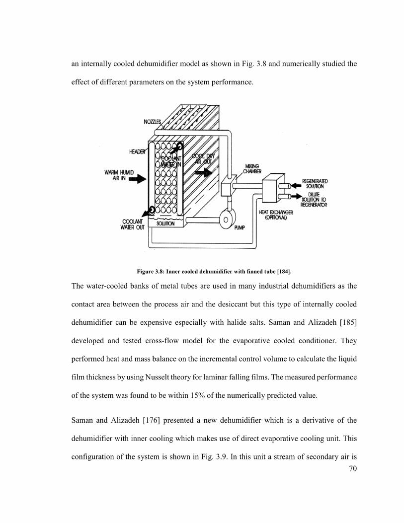
70
an internally cooled dehumidifier model as shown in Fig. 3.8 and numerically studied the
effect of different parameters on the system performance.
Figure 3.8: Inner cooled dehumidifier with finned tube [184].
The water-cooled banks of metal tubes are used in many industrial dehumidifiers as the
contact area between the process air and the desiccant but this type of internally cooled
dehumidifier can be expensive especially with halide salts. Saman and Alizadeh [185]
developed and tested cross-flow model for the evaporative cooled conditioner. They
performed heat and mass balance on the incremental control volume to calculate the liquid
film thickness by using Nusselt theory for laminar falling films. The measured performance
of the system was found to be within 15% of the numerically predicted value.
Saman and Alizadeh [176] presented a new dehumidifier which is a derivative of the
dehumidifier with inner cooling which makes use of direct evaporative cooling unit. This
configuration of the system is shown in Fig. 3.9. In this unit a stream of secondary air is
71
brought in contact with the spray of water in order to cool down the desiccant solution
flowing in another channel.
The droplet carryover from liquid desiccant dehumidifiers in which halide salts are used is
a dangerous and discouraging issue for air conditioning applications. This problem can be
eliminated by using internally cooled dehumidifiers which can work at relatively very low
flow rates. Laevemann et al. [186] and Lowenstein et al. [138] proposed desiccant
dehumidifiers in which desiccant is directly delivered onto the conditioner cooled plates.
The velocity of air at the gap is less than 4.5 m/s in this system which avoids the desiccant
carry over with the air.
Packed-bed is most commonly used for the contact surface between air and desiccant
solution and in some conditioners inner cooling is also utilized. The contact surface
between the air and the desiccant is a bundle of tubes and the material of these tubes
depends upon the nature of the desiccant material. For example, for halide salts copper
tubes are used to limit the corrosion problems. The desiccant is usually sprayed or dripped
onto these tubes and air is drawn past them. An internally cooled conditioner does not
require high thermal capacitance of the desiccant to lower the desiccant temperature during
absorption but for complete wetting of the packing, still high flow rate is required. Coil or
tube-type dehumidifiers are rarely used with halide salts desiccants because of corrosion
and high cost.

72
Figure 3.9: Inner cooled dehumidifier (cross flow): (a) directions of air flow (b) fluid sprays contacting with different air streams [176].
Mesquita et al. [187] developed three models of laminar flow and water-cooled liquid
desiccant conditioner. Using published data with simplest model, mass and energy balances
on a discrete control volume, heat and mass transfer coefficient between the air and the
desiccant was calculated. For concentration gradient and the temperature across the
desiccant and air films, the most sophisticated model was used in order to calculate the
thickness of the film. Queiroz et al. [188] developed a model for the calculation of
operating conditions for a non-adiabatic liquid desiccant dehumidifier. Triethylene glycol

73
and air flows counter currently outside the falling film staggered copper tubes. Water flows
inside the tubes to increase the mass transfer potential.
Yin et al. [189] designed an internally cooled/heated dehumidifier/regenerator based on
plate-fin heat exchanger (PFHE) as shown in Fig. 3.10. The schematic of PFHE is shown
in Fig. 3.10(a). The designed unit consists of six PFHEs stacking up along the vertical
direction as illustrated in Fig. 3.10(b). The effects of the air flow rate, cooling water
temperature, and desiccant solution temperature on cooling efficiency and the performance
of internally cooled dehumidifier were observed. The results showed that cooling
efficiency decreases with the increase in cooling water temperature and at lower desiccant
solution temperature, system has better dehumidification performance. It was also
concluded that internally cooled dehumidifier has better thermal performance as compared
to the adiabatic dehumidifier.
Khan and Martinez [190] studied the performance of internally cooled dehumidifier with
LiCl as the desiccant. The parameters like humidity and enthalpy effectiveness were used
to predict the thermal performance of the unit. The results showed that humidity and
enthalpy effectiveness are greatly affected by number of mass transfer units.
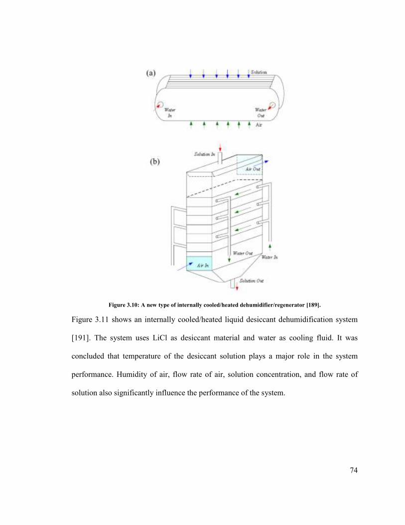
74
Figure 3.10: A new type of internally cooled/heated dehumidifier/regenerator [189].
Figure 3.11 shows an internally cooled/heated liquid desiccant dehumidification system
[191]. The system uses LiCl as desiccant material and water as cooling fluid. It was
concluded that temperature of the desiccant solution plays a major role in the system
performance. Humidity of air, flow rate of air, solution concentration, and flow rate of
solution also significantly influence the performance of the system.

75
Figure 3.11: Schematic of internally cooled/heated liquid desiccant dehumidification [191].
Khan and Sulsona [192] presented an internally cooled desiccant dehumidifier in which
solution of LiCl is uniformly sprayed over evaporator coil bundle as shown in Fig. 3.12.
The desiccant and air flows in counter flow arrangement. The cooling and dehumidification
of outside air is achieved by direct contact of air with the desiccant solution on the coil
surface. The weak desiccant solution is collected in a sump underneath the tube bundle.
The effect of desiccant temperature, process air temperature on the system performance
was analyzed in this study.
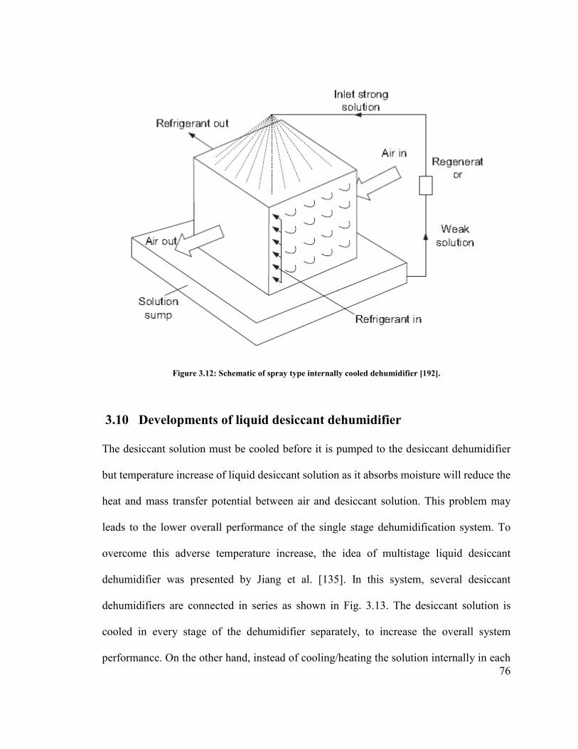
76
Figure 3.12: Schematic of spray type internally cooled dehumidifier [192].
3.10 Developments of liquid desiccant dehumidifier
The desiccant solution must be cooled before it is pumped to the desiccant dehumidifier
but temperature increase of liquid desiccant solution as it absorbs moisture will reduce the
heat and mass transfer potential between air and desiccant solution. This problem may
leads to the lower overall performance of the single stage dehumidification system. To
overcome this adverse temperature increase, the idea of multistage liquid desiccant
dehumidifier was presented by Jiang et al. [135]. In this system, several desiccant
dehumidifiers are connected in series as shown in Fig. 3.13. The desiccant solution is
cooled in every stage of the dehumidifier separately, to increase the overall system
performance. On the other hand, instead of cooling/heating the solution internally in each

77
stage of dehumidifier, the system performance can be improved by cooling/heating the
desiccant solution using some external auxiliary cooling/heating medium as shown in Fig.
3.14 [193]. Li [194] studied and compared irreversible losses for multistage dehumidifier
and conventional single stage dehumidifier.
Figure 3.13: Multi-stage liquid desiccant dehumidifier [135].
Figure 3.14: Dehumidifier/regenerator with auxiliary cooling/heating module [193].
Xiong et al. [195] observed an increase in the system COP from 0.23 to 0.72 by using a
two-stage novel liquid desiccant cooling system which is shown in Fig. 3.15. On the
process side, the air is first dehumidified in the first dehumidifier (1st DEH) using solution

78
of CaCl2 and then, in the second dehumidifier (2nd DEH) air is further dehumidified by
solution of LiCl up to the desired humidity of air. Kumar et al. [196] carried out the
performance analysis of falling film liquid desiccant dehumidifier operating on two new
liquid desiccant cycles (Multi-absorber cycles) and found that performance of the system
is improved significantly by using these cycles.
Figure 3.15: Two-stage liquid desiccant dehumidification system [195].
Xiong et al. [197] studied a two stage liquid desiccant dehumidification system using two
desiccant materials (LiCl and CaCl2). In this system, the air is pre-dehumidified in the first
stage using CaCl2 and then further dehumidified using LiCl. The results showed that
investment cost can be reduced by about 53% as compared to single stage dehumidification
using LiCl because CaCl2 is much cheaper than LiCl.

79
The parallel-plates membrane modules can be used as air to air heat and mass exchanger
[198]. Figure 3.16 [199] shows parallel-plates membrane module used as liquid desiccant
dehumidifier. The flow channels were created by keeping the equal spacing between the
membrane modules. The desiccant solution and air flows through the flow channels in
counter-flow arrangement. The desiccant solution absorbs the moisture from the air
through the membrane, eliminating the problem of desiccant carry over.
Figure 3.16: Structure of a parallel-plate membrane module [199].
A flat plate internally cooled dehumidifier using water as the cooling fluid is shown in Fig.
3.17 [200]. Cooling water is circulated through the polypropylene double plates. The air
flows upward and desiccant solution flows downward across the polypropylene plates. For
uniform flow of the desiccant solution, a desiccant distributer is provided on top of each
plate. The corrugated plate internally cooled dehumidifier is shown in Fig. 3.18 [201].
Results showed that corrugated plate dehumidifier has better performance as compared to

80
the flat plate dehumidifier (shown in Fig. 3.9) because of better cooling performance and
air turbulence.
Figure 3.17: Internally cooled vertical flat plate dehumidifier [95]. (a) Side view; (b) Inner view.
Figure 3.18: Internally cooled dehumidifier with corrugated plates [201].
Cheng [202] developed a liquid desiccant dehumidifier using fin-plastic tube heat
exchanger. The developed system has great potential for corrosion prevention and can be
used as internally cooled/heated dehumidifier/regenerator. Considering the advantages of
multistage liquid desiccant dehumidifier, the membrane based liquid desiccant
dehumidifier can also be extended to multistage configuration, where packed bed columns
are replaced by membrane modules as shown in Fig. 3.19 [193].
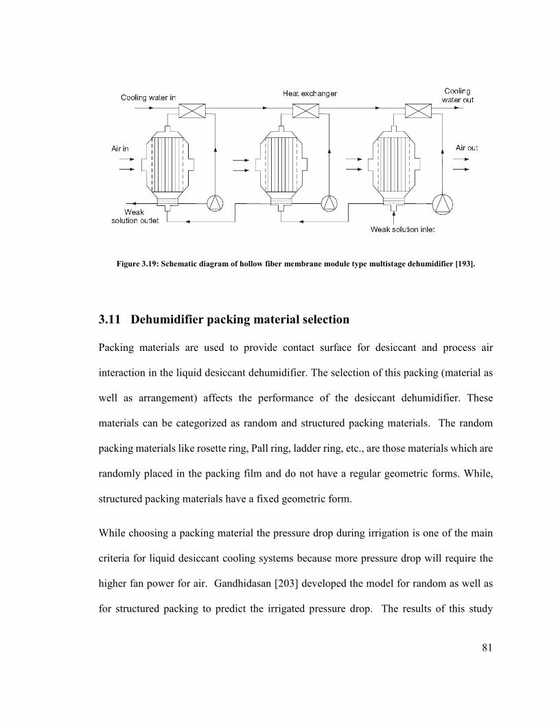
81
Figure 3.19: Schematic diagram of hollow fiber membrane module type multistage dehumidifier [193].
3.11 Dehumidifier packing material selection
Packing materials are used to provide contact surface for desiccant and process air
interaction in the liquid desiccant dehumidifier. The selection of this packing (material as
well as arrangement) affects the performance of the desiccant dehumidifier. These
materials can be categorized as random and structured packing materials. The random
packing materials like rosette ring, Pall ring, ladder ring, etc., are those materials which are
randomly placed in the packing film and do not have a regular geometric forms. While,
structured packing materials have a fixed geometric form.
While choosing a packing material the pressure drop during irrigation is one of the main
criteria for liquid desiccant cooling systems because more pressure drop will require the
higher fan power for air. Gandhidasan [203] developed the model for random as well as
for structured packing to predict the irrigated pressure drop. The results of this study

82
showed that the structured packing is better in term of pressure drop as compared to the
random packing for liquid desiccant cooling systems.
To predict the performances of both packing materials comparative experiments were
conducted on random as well as structured packing materials by Chung et al. [204]. Bravo
et al. [205] concluded that structured packing has higher efficiency and more capacity for
mass and heat transfer materials with lower pressure drop.
The factors such as, volumetric area of packing material, void volume, and spacing
intervals between the layers of packing materials are used to evaluate the contacting surface
area between air and the desiccant material. The resistance to air flow can be measured by
void ratio, which relates inversely with the spacing interval. An optimum value of spacing
interval between layers of packing will cause less inlet air resistance and also increase the
coverage ratio of the sprinkled desiccant on the packing material. Normally the spacing
interval lies between 6–8 mm.
Another important parameter to predict the heat and mass transfer within the packing
material is the droplets diameter. Al-Farayadhi et al. [206] defined an equivalent diameter
of structured packing materials by taking the arithmetic average of hydraulic diameter of
different flow sections using flow channel of different cross sections.
The wetting ratio or effective interfacial area of packing materials is another essential factor
to predict the packing material heat and mass transfer performance. The wetting ratio
mainly depends on cross sections, flow channels, and surface characteristics of the
desiccant material. A correlation for mass transfer coefficient was developed by Shi and

83
Mersmann [207] on the bases of the packing column principles of effective mass transfer.
Gandhidasan [208] compared the three available models used to calculate the effective
interfacial area of packing materials.
Height, length and quality of packing are also very important along with the selections of
packing materials. The quality of packing means there should be no distortion if the
packing is socked in a liquid desiccant for a long period of time and the layers of the
packing material should be strong enough to withstand the required inlet air velocity.
3.12 Flow pattern inside the dehumidifier
Generally parallel, counter and cross flow configurations are used for the liquid desiccant
dehumidifiers. For the analysis of dehumidification process finite difference model [209-
211], ε -NTU model [212,213], and fitted algebraic equations model [214,215], are
commonly used. From these three models the most accurate performance analysis with
basic equations is provided by the finite difference model.
Rahamah et al. [216] theoretically analyzed the parallel flow desiccant dehumidification
system using control volume approach. The results of the analysis showed that better
dehumidification and cooling can be obtained by using low air flow rate (mass transfer will
be increased because of the more air-desiccant contacting time) and large channel height
(air-desiccant contact area will be enlarged).
Rahamah et al. [217] made an investigation of different performance controlling
parameters of liquid desiccant system for a fin-tube channel with a parallel flow
configuration. Elsayed et al. [218] numerically analyzed the characteristics for transfer of

84
mass and heat between air and solution of CaCl2 using counter flow configuration in a
packed bed dehumidifier and developed a chart to predict the exit air temperature and
humidity.
Lazzarin [219] developed a heat and mass transfer model for packed bed liquid desiccant
dehumidifier and carried out a parametric study using solution of H2O/LiBr and
H2O/CaCl2, to determine the optimum operating conditions for the packed bed
dehumidifier. Dai and Zhang [220] developed the mathematical model for liquid desiccant
dehumidification system in a cross flow configuration by employing packing material of
honey comb paper to determine the Sherwood and Nusselt numbers at the interface of air
and liquid desiccant.
Ali et al. [221] studied the effects on transfer of heat and mass between streams of air and
liquid desiccant in a cross flow dehumidifier by adding Cu-ultra fine particles. It was
observed that Cu-ultra fine particles addition stabilize the desiccant solution and increases
the transfer rate of heat and mass between two streams.
Liu et al. [222] investigated a liquid desiccant dehumidifier consists of honeycomb paper
packing in a cross flow arrangement and provided the distribution of temperature and
humidity of air within the packing materials. The desiccant solution concentration in the
layers of packing material was also analyzed by them. For the internally cooled
dehumidifiers, water, air, ammonia, and R22 [223] are commonly used as the cooling fluid
with cooling fluid-desiccant flow pattern either cross [224] or counter [190]. The air-
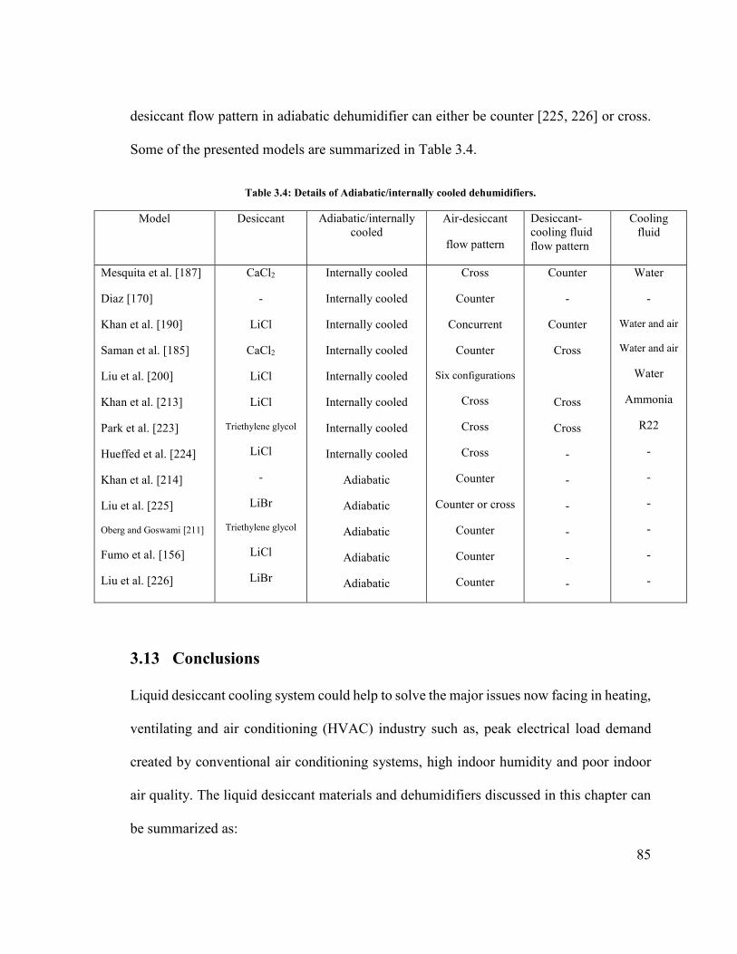
85
desiccant flow pattern in adiabatic dehumidifier can either be counter [225, 226] or cross.
Some of the presented models are summarized in Table 3.4.
Table 3.4: Details of Adiabatic/internally cooled dehumidifiers.
Model Desiccant Adiabatic/internally cooled
Air-desiccant
flow pattern
Desiccant-cooling fluid flow pattern
Cooling fluid
Mesquita et al. [187]
Diaz [170]
Khan et al. [190]
Saman et al. [185]
Liu et al. [200]
Khan et al. [213]
Park et al. [223]
Hueffed et al. [224]
Khan et al. [214]
Liu et al. [225]
Oberg and Goswami [211]
Fumo et al. [156]
Liu et al. [226]
CaCl2
-
LiCl
CaCl2
LiCl
LiCl
Triethylene glycol
LiCl
-
LiBr
Triethylene glycol
LiCl
LiBr
Internally cooled
Internally cooled
Internally cooled
Internally cooled
Internally cooled
Internally cooled
Internally cooled
Internally cooled
Adiabatic
Adiabatic
Adiabatic
Adiabatic
Adiabatic
Cross
Counter
Concurrent
Counter
Six configurations
Cross
Cross
Cross
Counter
Counter or cross
Counter
Counter
Counter
Counter
-
Counter
Cross
Cross
Cross
-
-
-
-
-
-
Water
-
Water and air
Water and air
Water
Ammonia
R22
-
-
-
-
-
-
3.13 Conclusions
Liquid desiccant cooling system could help to solve the major issues now facing in heating,
ventilating and air conditioning (HVAC) industry such as, peak electrical load demand
created by conventional air conditioning systems, high indoor humidity and poor indoor
air quality. The liquid desiccant materials and dehumidifiers discussed in this chapter can
be summarized as:

86
• The liquid desiccant should be non-corrosive and non-volatile for a HVAC
application. The most commonly used industrial liquid desiccants are LiCl, LiBr,
CaCl2, and triethylene glycol.
• LiCl has lowest vapor pressure and is most stable liquid desiccant but have high
cost. The economic issue of LiCl can be resolved by using it in combination with
CaCl2, which is readily available and the cheapest desiccant.
• To improve the characteristics of a single desiccant material such as to improve its
absorption capability and to lower its regeneration temperature, a number of
composite desiccant materials have been developed.
• Desiccant dehumidifier is the heart of a liquid desiccant cooling system which is
mostly of adiabatic type or inner cooled. The adiabatic type dehumidifier requires
high flow rates for complete wetting of the surface which causes desiccant carry
over. This problem of required high flow rates and carry over can be avoided by
using inner cooled dehumidifier.
• A rotary type of liquid desiccant dehumidifier is proposed for lower pressure drop
and to avoid desiccant carry over in which a porous medium such as, thick cloth
can be used to carry the desiccant solution inside a rotor disc.
• The corrosive nature of a desiccant can be dealt with very low flow rate of the
desiccant both in the dehumidifier and the regenerator. To operate the system at
these low flow rates continuous cooling of the desiccant in the dehumidifier is
required which have been done by many researchers by proposing different
configurations of inner cooled dehumidifiers.
87
• To overcome the problem of droplet carryover a new type of liquid-air membrane
heat and mass exchanger in counter flow arrangement as dehumidifier has been
proposed and they provide the better performance. Further, multistage membrane
based liquid desiccant dehumidifier would be the future development of liquid
desiccant dehumidification systems.
• The selection of packing material, its arrangement and flow pattern inside the
desiccant dehumidifier are important for its performance.
• More field work is required to design and specify liquid desiccant cooling systems
which can comfortably replace the conventional air conditioners.
3.14 Objectives of the present work
Some primary objectives of the present study are:
• Literature review of desiccant cooling cycles.
• Literature review of desiccant based evaporative cooling systems.
• Literature review of liquid desiccant materials.
• Feasibility analysis of solid desiccant cooling system in conjunction with
evaporative coolers under climatic zone of Dhahran, Saudi Arabia.
• Modeling and performance investigation of a rotary liquid desiccant dehumidifier.
• Design and manufacturing of a compact liquid desiccant dehumidifier with electric
heater as regeneration source.
• Testing the manufactured dehumidifier.

88
4 CHAPTER 4
MATHEMATICAL MODELING OF LIQUID
DESICCANT WHEEL
The liquid desiccant cooling system is found to be a good alternative of conventional air
conditioning system for better control of both latent and sensible loads. The major
component of a liquid desiccant cooling system is desiccant dehumidifier which controls
the latent cooling load. In this chapter a mathematical model for a newly proposed rotary
type liquid desiccant dehumidifier has been presented. The dehumidifier has a cylindrical
shape with a number of identical narrow circular slots, distributed uniformly over the rotor
cross section. This type of dehumidifier is commonly known as desiccant wheel. The
energy and exergetic performance of the dehumidification system is discussed in this
chapter for different operating conditions. The wheel performance curves which help to
optimize the performance of the dehumidifier are drawn for a wide range of wheel
rotational speeds (0.5 – 7 rpm), wheel width (0.1 – 0.6 m), air mass flux (1 – 8 kg/m2.s),
and regeneration temperature (50 – 90oC). Furthermore, a feasibility analysis of the
proposed dehumidification system has been carried out for climatic conditions of Dhahran,
Saudi Arabia. The computed results show that better supply air conditions can be obtained
to provide human comfort in the hot and humid climate with effectiveness of the system
largely dependent on air flow rate, wheel width and humidity ratio of process air.
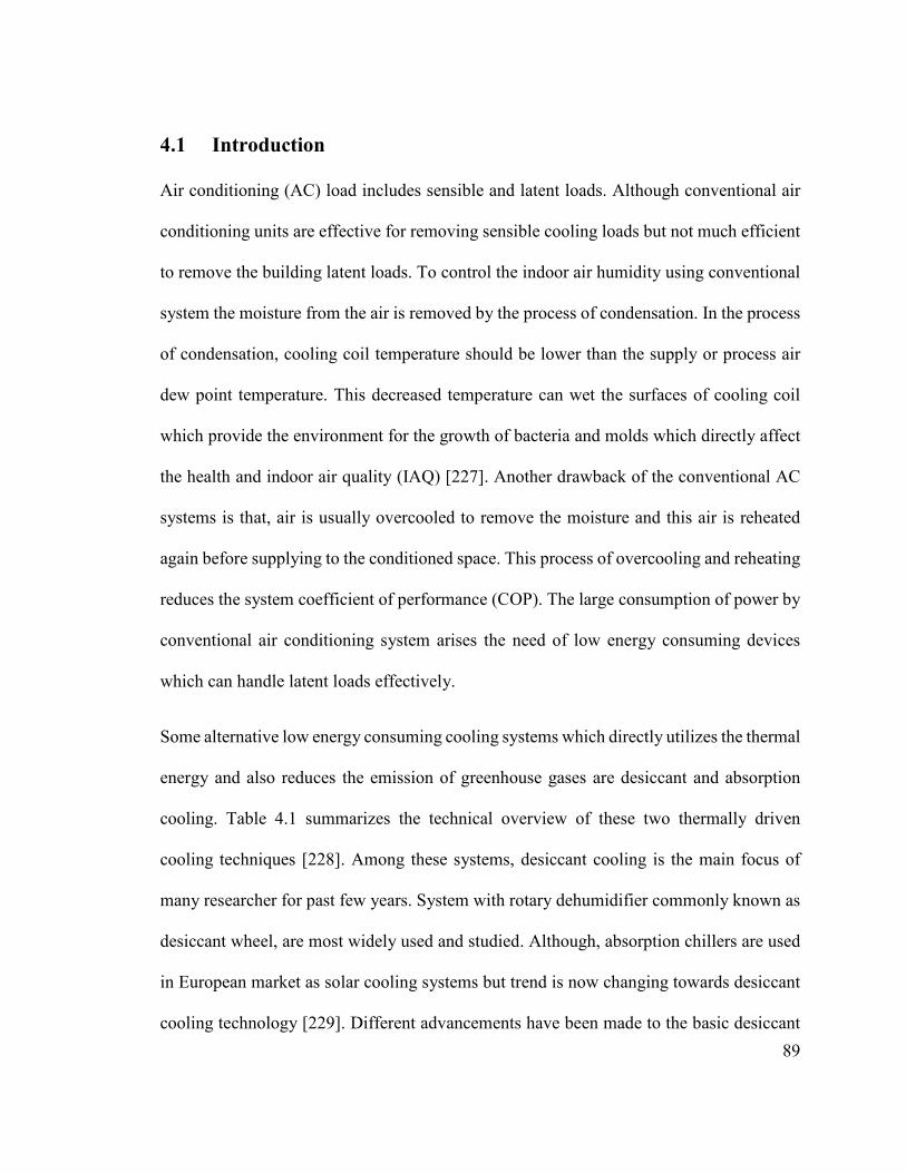
89
4.1 Introduction
Air conditioning (AC) load includes sensible and latent loads. Although conventional air
conditioning units are effective for removing sensible cooling loads but not much efficient
to remove the building latent loads. To control the indoor air humidity using conventional
system the moisture from the air is removed by the process of condensation. In the process
of condensation, cooling coil temperature should be lower than the supply or process air
dew point temperature. This decreased temperature can wet the surfaces of cooling coil
which provide the environment for the growth of bacteria and molds which directly affect
the health and indoor air quality (IAQ) [227]. Another drawback of the conventional AC
systems is that, air is usually overcooled to remove the moisture and this air is reheated
again before supplying to the conditioned space. This process of overcooling and reheating
reduces the system coefficient of performance (COP). The large consumption of power by
conventional air conditioning system arises the need of low energy consuming devices
which can handle latent loads effectively.
Some alternative low energy consuming cooling systems which directly utilizes the thermal
energy and also reduces the emission of greenhouse gases are desiccant and absorption
cooling. Table 4.1 summarizes the technical overview of these two thermally driven
cooling techniques [228]. Among these systems, desiccant cooling is the main focus of
many researcher for past few years. System with rotary dehumidifier commonly known as
desiccant wheel, are most widely used and studied. Although, absorption chillers are used
in European market as solar cooling systems but trend is now changing towards desiccant
cooling technology [229]. Different advancements have been made to the basic desiccant

90
cooling cycle to improve the system efficiency. The basic advantages of desiccant cooling
can be summarized as:
• The energy cost is significantly reduced.
• Free, low grade thermal energy sources such as solar, waste heat, etc. can be used
to provide regeneration heat.
• Environmental friendly because of no emission of greenhouse gases since no
chlorofluorocarbon based refrigerant is used.
• The sensible and latent cooling loads are independently and efficiently controlled.
The desiccant cooling system can either be solid or liquid depending upon the type of
desiccant material used. Liquid desiccants have advantage over the solid desiccants that
these only requires low temperature heat source (60–80oC) to drive the system. This makes
the use of some renewable energy resources like solar, biomass, etc. more feasible and
efficient. A comparison between liquid and solid desiccant cooling system have been
presented in Table 4.2 [230]. Liquid desiccant cooling system (LDCS) compromises of a
liquid dehumidification cycle accompanied by cooling process that is, evaporative cooling.
The dehumidification cycle includes the dehumidification of process air and regeneration
of liquid desiccant and this cycle controls most of the building latent cooling load. The
analysis of liquid desiccant cooling processes help to understand the drawbacks and
advantages of the system.
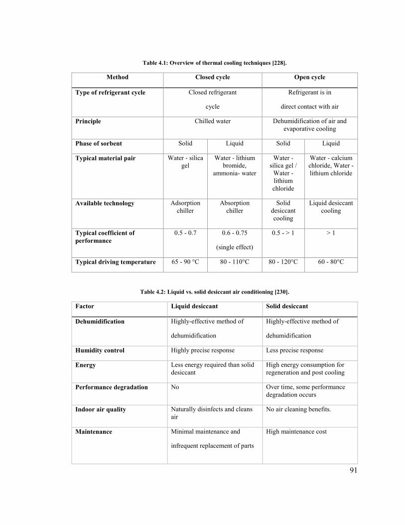
91
Table 4.1: Overview of thermal cooling techniques [228].
Method Closed cycle Open cycle
Type of refrigerant cycle Closed refrigerant
cycle
Refrigerant is in
direct contact with air
Principle Chilled water Dehumidification of air and evaporative cooling
Phase of sorbent Solid Liquid Solid Liquid
Typical material pair Water - silica gel
Water - lithium bromide,
ammonia- water
Water - silica gel /
Water - lithium chloride
Water - calcium chloride, Water - lithium chloride
Available technology Adsorption chiller
Absorption chiller
Solid desiccant cooling
Liquid desiccant cooling
Typical coefficient of performance
0.5 - 0.7 0.6 - 0.75
(single effect)
0.5 - > 1 > 1
Typical driving temperature 65 - 90 °C 80 - 110°C 80 - 120°C 60 - 80°C
Table 4.2: Liquid vs. solid desiccant air conditioning [230].
Factor Liquid desiccant Solid desiccant
Dehumidification Highly-effective method of
dehumidification
Highly-effective method of
dehumidification
Humidity control Highly precise response Less precise response
Energy Less energy required than solid desiccant
High energy consumption for regeneration and post cooling
Performance degradation No Over time, some performance degradation occurs
Indoor air quality Naturally disinfects and cleans air
No air cleaning benefits.
Maintenance Minimal maintenance and
infrequent replacement of parts
High maintenance cost

92
Most of the studies carried out for LDCSs are direct contact type in which there is a direct
contact between liquid desiccant and air streams. Direct contact type system has a
drawback that supply air can carry some liquid desiccant droplets with it, which can cause
corrosion of ducting and other equipment. This will increase the maintenance costs and
will decrease the equipment life. Secondly, desiccant carryover can affect the indoor air
quality which will directly affect the human health within the conditioned space. Direct
contact type system also requires high fan and pumping power because of the higher
pressure drop and for continuous supply of desiccant solution. To overcome this problem,
a porous medium can be used to carry the liquid desiccant solution in a rotary wheel. These
wheels have lower pressure drops as compared to packed bed dehumidifiers and at the
same time providing large surface area for contact between desiccant and humid air. In the
past, most of the investigations had been carried out for solid desiccant rotary dehumidifier
and very few work have been carried out on the rotary liquid desiccant dehumidifier [231].
Some general advantages of using rotary desiccant wheel are:
• These systems are more convenient to install.
• Dehumidification and regeneration are carried out synchronously in these systems
and the system runs continuously.
• These systems occupy a smaller space but offering more contact surface area with
air than the packed bed dehumidifiers.
• Dehumidification/regeneration capacity of the dehumidifier can be efficiently
controlled by changing the rotational speed of the desiccant wheel.
93
The main objective of this research is to provide the research community with practical
and reliable liquid desiccant rotary dehumidification system. As desiccant dehumidifier is
the most crucial component of the desiccant cooling system, mathematical modeling of
desiccant dehumidifier has a significant effect on overall system performance. The wheel
dimensions and speed, and operating parameters such as ambient conditions, regeneration
temperature, and air flow rate had already been optimized for better performance of the
solid desiccant system. However, effective work needs to be conducted for absorption type
rotary dehumidifiers.
In this chapter a mathematical model is developed to study and discuss the performance of
a newly proposed rotary type liquid desiccant dehumidifier in terms of its dehumidification
performance, effectiveness, and sensible energy ratio considering different parameters
such as the air flow rates, regeneration temperature, and wheel speed. Also, the effect of
ambient conditions on dehumidifier performance has been examined. Furthermore, a
feasibility analysis of the proposed system have been carried out for the climatic conditions
of Dhahran, Saudi Arabia keeping in view of a vast amount of energy is used for air
conditioning in the Kingdom.
4.2 Mathematical modeling
4.2.1 System description
The proposed liquid desiccant dehumidifier is a rotary wheel of radius R and width L. The
rotor consists of number of identical narrow slots uniformly distributed over its cross-
section as shown in Fig. 4.1. The slots are covered with porous media impregnated with
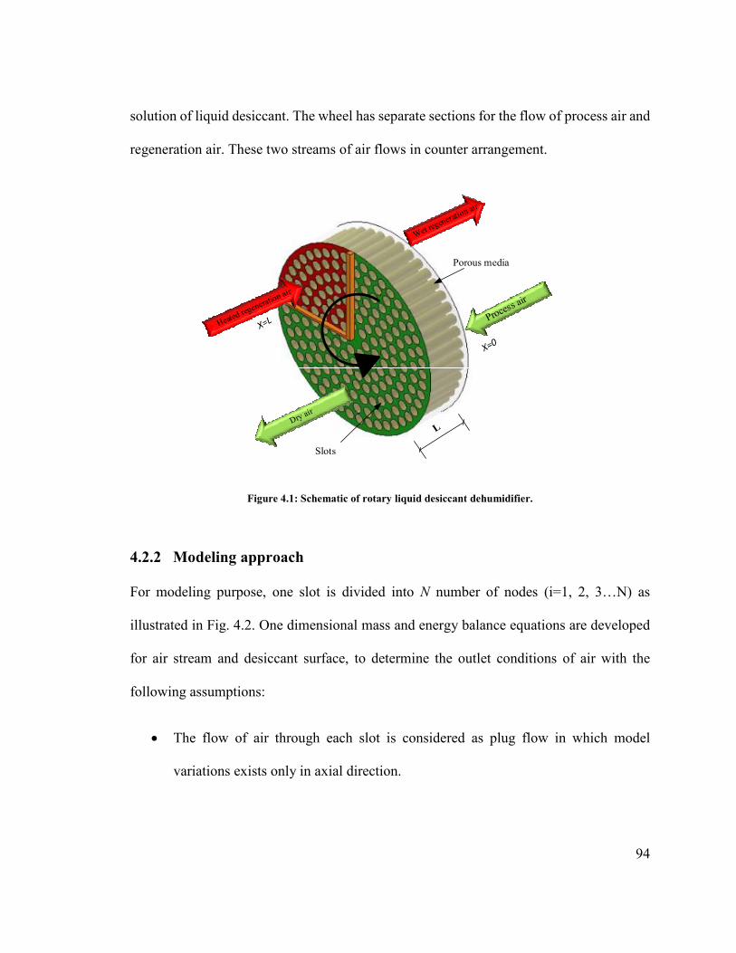
94
solution of liquid desiccant. The wheel has separate sections for the flow of process air and
regeneration air. These two streams of air flows in counter arrangement.
Slots
Porous media
Figure 4.1: Schematic of rotary liquid desiccant dehumidifier.
4.2.2 Modeling approach
For modeling purpose, one slot is divided into N number of nodes (i=1, 2, 3…N) as
illustrated in Fig. 4.2. One dimensional mass and energy balance equations are developed
for air stream and desiccant surface, to determine the outlet conditions of air with the
following assumptions:
• The flow of air through each slot is considered as plug flow in which model
variations exists only in axial direction.

95
• The air is assumed to be distributed uniformly across dehumidification and
regeneration sections.
• The axial heat conduction and mass diffusion are neglected.
• It is assumed that there is no carry-over of the desiccant solution.
• The thermodynamic properties are assumed as constant.
• Each slot is assumed to be adiabatic.
The process air directly contact with the desiccant surface. Water vapor are absorbed by
the desiccant from the process humid air because of the higher partial pressure of water
vapor in air as compared to the surface of desiccant. The released vaporization heat causes
an increase in desiccant temperature which increases the desiccant surface vapor pressure
and causes a decrease in dehumidification process.
Figure 4.2: Pattern of flow in a slot.
4.2.3 Governing equations
The difference of vapor pressure between air and desiccant surface acts as driving force for
mass transfer. For a control volume, air stream and desiccant surface moisture balance can

96
be written in terms of moisture variations and convective mass transfer between humid air
and desiccant.
Mass balance on humid air stream:
cA L( ) ( )ω ωρ ω ω−∂ ∂+ =∂ ∂
a aa h s au kA
t x (4.1)
Mass balance on desiccant surface:
c hA ( ) A ( )ω
ρ ω ω∂ ∂
+ = −∂ ∂
sd s a
wL k
t t (4.2)
The sensible and latent heat is transferred between air and desiccant due to convection and
adsorption phenomenon. Therefore, the energy balance for air stream and desiccant surface
can be written as:
Energy balance on the air stream:
pa c pv c sC L( ) A ( ) C kA ( )( )a ah a t s a a s a
T TA u h T T T Tt x
ρ ω ω− −∂ ∂+ = + −∂ ∂ (4.3)
Energy balance on the desiccant surface:
c c pv c( ) A ( ) A ( ) C A ( )( )ρ ω ω ω ω∂
= − + − + − −∂
spd d h t a s a s fg a s a s
TC A L h T T k h T T
t (4.4)
The humidity on the desiccant surface can be evaluated in terms of saturated water vapor
pressure on the surface of desiccant:
97
5
0.0622
1.0133 10ω =
× −v
s
v
p
p (4.5)
Saturated water vapor pressure on the desiccant surface is given as [232]:
3816.4423.196
46.14Tsvp e
− − = (4.6)
Coefficient of heat and mass transfer for rotary type liquid desiccant dehumidifiers can be
expressed as [233]:
0.510.704. .Reak m −= & (4.7)
0.510.671. . Re .t a pah m C−= & (4.8)
4.3 Boundary and initial conditions
The flow of process air and regeneration air are in counter-flow arrangements. The
boundary conditions for temperature and humidity ratio can be written as:
Process air enters the channel at axial distance L = 0:
,(0, )a p iT t T= (4.9)
,(0, )a p itω ω= (4.10)
Regeneration air enters the channel at axial distance L:
,( , )a r iT L t T= (4.11)
,( , )a r iL tω ω= (4.12)
98
The initial conditions for temperature and humidity ratio are [234]:
,(x, 0)a p iT T= (4.13)
,(x, 0)s r iT T= (4.14)
,(x, 0)a p iω ω= (4.15)
w(x, 0) w i= (4.16)
4.4 Performance index
The primary purpose of the desiccant dehumidifier is to dehumidify the air. The
dehumidification capacity is represented by moisture removal which is the amount of water
desorbed from the process air by the desiccant. Moisture removal capacity of the desiccant
dehumidifier can be written as:
= = �� > × (AB,D − AB,F) (4.17)
Latent effectiveness of the dehumidifier is given as:
ℇ = (GH,IJGH,K)(GH,IJGH,K ILMHN) (4.18)
Where, AB,FO DPQBR represents the ideal specific humidity ratio. Assuming that at this point
air is completely dehumidified, AB,F DPQBR=0.
Dehumidification coefficient of performance (DCOP) is another parameter used to
represent the desiccant dehumidifier capacity to dehumidify the air. For the different mass
flow rates of process and regeneration air, DCOP is given as:
99
STUV = W� X×YZ[×(GH,IJGH,K)W� \×(Y\JYH]^) (4.19)
A higher DCOP indicates a better system performance because the energy input to the
regeneration air is utilized in a better way or less heat is being used to heat up the desiccant.
The sensible energy ratio (SER) is also used when evaluating the desiccant dehumidifier.
The SER can quantify additional sensible load to be handled by some additional cooling
mechanism at the downstream such as an evaporative cooling or a vapor compression
cycle. The SER is given by:
_`a = W� X×(bH,KJbH,I)W� \× (b\Jb H]^) (4.20)
For better dehumidification performance of the desiccant wheel the value of SER should
be lower. The higher value of SER means more cooling load on the cooling device because
of higher temperature of process air at exist of desiccant wheel. Lower values of SER mean
that the desiccant dehumidifier is creating a lower sensible cooling load, which indicates
better performance of the system.
4.5 Results and discussions
A rotary type liquid desiccant dehumidifier is proposed in this paper to have lower
regeneration temperature, no carryover of desiccant solution and better supply air
conditions. A code has been developed in Engineering Equation solver (EES) using
mathematical model and performance of the system is investigated under geometric and
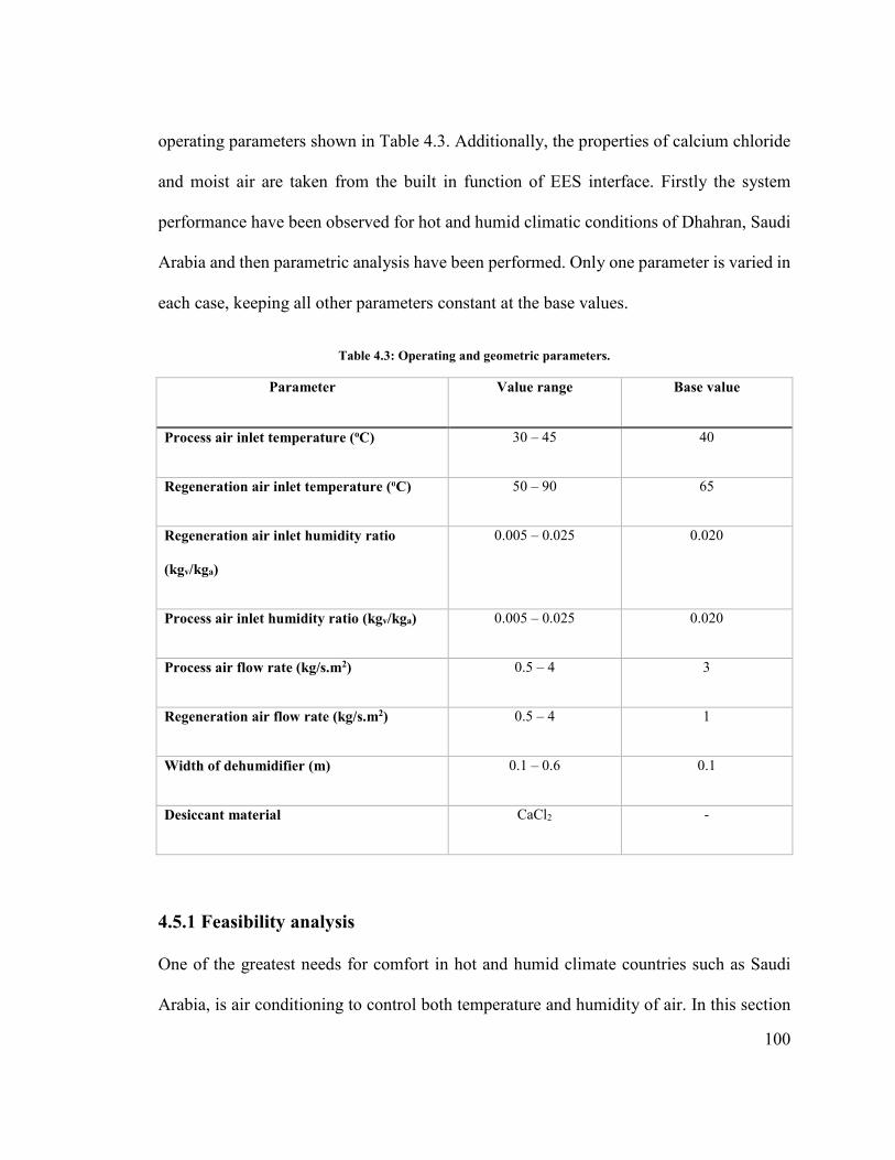
100
operating parameters shown in Table 4.3. Additionally, the properties of calcium chloride
and moist air are taken from the built in function of EES interface. Firstly the system
performance have been observed for hot and humid climatic conditions of Dhahran, Saudi
Arabia and then parametric analysis have been performed. Only one parameter is varied in
each case, keeping all other parameters constant at the base values.
Table 4.3: Operating and geometric parameters.
Parameter Value range Base value
Process air inlet temperature (oC) 30 – 45 40
Regeneration air inlet temperature (oC) 50 – 90 65
Regeneration air inlet humidity ratio
(kgv/kga)
0.005 – 0.025 0.020
Process air inlet humidity ratio (kgv/kga) 0.005 – 0.025 0.020
Process air flow rate (kg/s.m2) 0.5 – 4 3
Regeneration air flow rate (kg/s.m2) 0.5 – 4 1
Width of dehumidifier (m) 0.1 – 0.6 0.1
Desiccant material CaCl2 -
4.5.1 Feasibility analysis
One of the greatest needs for comfort in hot and humid climate countries such as Saudi
Arabia, is air conditioning to control both temperature and humidity of air. In this section
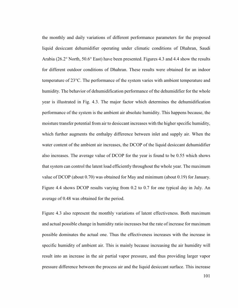
101
the monthly and daily variations of different performance parameters for the proposed
liquid desiccant dehumidifier operating under climatic conditions of Dhahran, Saudi
Arabia (26.2° North, 50.6° East) have been presented. Figures 4.3 and 4.4 show the results
for different outdoor conditions of Dhahran. These results were obtained for an indoor
temperature of 23°C. The performance of the system varies with ambient temperature and
humidity. The behavior of dehumidification performance of the dehumidifier for the whole
year is illustrated in Fig. 4.3. The major factor which determines the dehumidification
performance of the system is the ambient air absolute humidity. This happens because, the
moisture transfer potential from air to desiccant increases with the higher specific humidity,
which further augments the enthalpy difference between inlet and supply air. When the
water content of the ambient air increases, the DCOP of the liquid desiccant dehumidifier
also increases. The average value of DCOP for the year is found to be 0.55 which shows
that system can control the latent load efficiently throughout the whole year. The maximum
value of DCOP (about 0.70) was obtained for May and minimum (about 0.19) for January.
Figure 4.4 shows DCOP results varying from 0.2 to 0.7 for one typical day in July. An
average of 0.48 was obtained for the period.
Figure 4.3 also represent the monthly variations of latent effectiveness. Both maximum
and actual possible change in humidity ratio increases but the rate of increase for maximum
possible dominates the actual one. Thus the effectiveness increases with the increase in
specific humidity of ambient air. This is mainly because increasing the air humidity will
result into an increase in the air partial vapor pressure, and thus providing larger vapor
pressure difference between the process air and the liquid desiccant surface. This increase

102
in the vapor pressure difference is accompanied by an increase in the desiccant moisture
absorption capacity and dehumidifier effectiveness. The maximum values of wheel
effectiveness achieved was 0.76 for the month of May and September, while a minimum
effectiveness value of 0.50 was obtained for the month of January. The hourly variations
of effectiveness are not significant as it can be observed from Fig. 4.4. Effectiveness results
varies from 0.60 to 0.64 for one typical day in July with an average of value of 0.63.
The monthly moisture removal capacity of desiccant dehumidifier from the process air is
presented in Fig. 4.3. The removed moisture depends on different parameters such as inlet
air humidity ratio, air flow rate and the desiccant wheel material. The removed moisture is
following the same trend as the humidity of inlet air for all months. The change in specific
humidity and moisture removal capacity increase with the increase in inlet air specific
humidity. The maximum amount of moisture removed from the process air is 0.026 kg/s
for the month of September. The moisture removal capacity varies from 0.008 to 0.020
kg/s for one typical day in July as illustrated in Fig. 4.4.
Figure 4.3 also shows the monthly variations of sensible energy ratio (SER). The value of
SER depends on ambient conditions that is, temperature and humidity ratio. The maximum
and minimum value of sensible energy ratio are 0.85 and 0.09 for the month of July and
January, respectively. Figure 4.4 shows SER results varying from 0.60 to 0.88 for one
typical day in July. An average of 0.73 was obtained for the period.
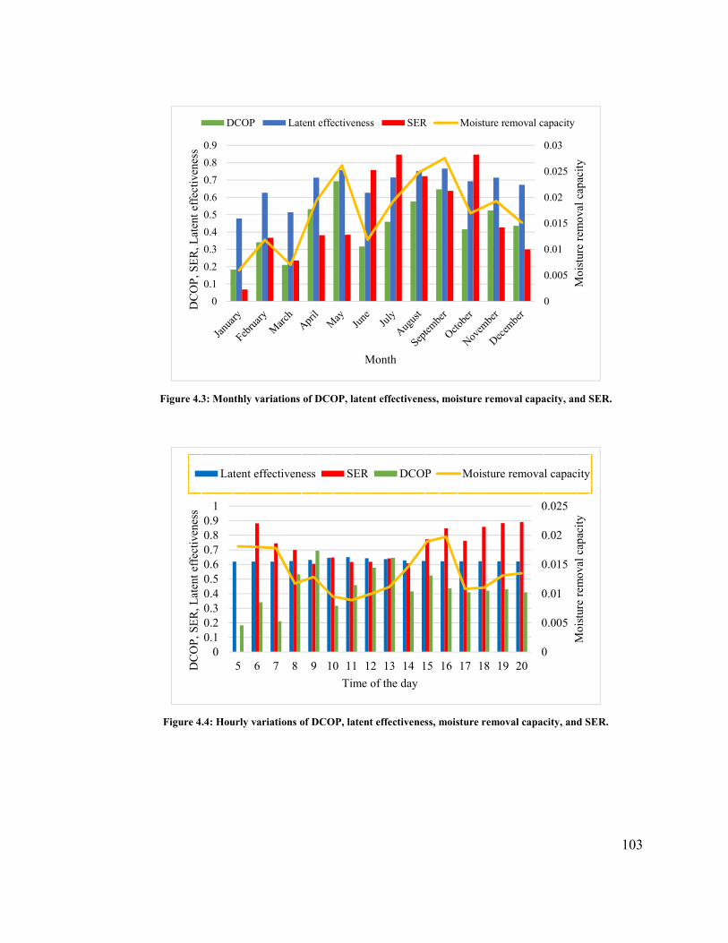
103
Figure 4.3: Monthly variations of DCOP, latent effectiveness, moisture removal capacity, and SER.
Figure 4.4: Hourly variations of DCOP, latent effectiveness, moisture removal capacity, and SER.
0
0.005
0.01
0.015
0.02
0.025
0.03
0
0.1
0.2
0.3
0.4
0.5
0.6
0.7
0.8
0.9
Moi
stur
e re
mov
al c
apac
ity
DC
OP
, SE
R, L
aten
t ef
fect
iven
ess
Month
DCOP Latent effectiveness SER Moisture removal capacity
0
0.005
0.01
0.015
0.02
0.025
00.10.20.30.40.50.60.70.80.9
1
5 6 7 8 9 10 11 12 13 14 15 16 17 18 19 20
Moi
stur
e re
mov
al c
apac
ity
DC
OP
, SE
R, L
aten
t ef
fect
iven
ess
Time of the day
Latent effectiveness SER DCOP Moisture removal capacity

104
4.5.2 Parametric analysis
The difference of temperature and vapor pressure between air and desiccant streams acts
as driving force for transfer of heat and mass, respectively. The effect of process air mass
flux on heat and mass transfer coefficients is shown in Fig. 4.5. Both coefficients increase
as process air mass flux increases because of increase in driving force for heat and mass
transfer. As the air mass flux increases from 0.01 to 4 kg/m2.s, an increase from 1 to 13
W/m2.K and 0.002 to 0.04 kg/m2.s is observed in the heat and mass transfer coefficients,
respectively. The increase in mass transfer coefficient causes a better transfer of moisture
from humid air to the desiccant which increases the dehumidification capacity of the
desiccant dehumidifier.
The effect of process air mass flux on exit air humidity ratio for different width of the rotary
dehumidifier is illustrated in Fig. 4.6. The exit air humidity ratio increases with the increase
in air mass flux which shows a decrease in air dehumidification with the increase in mass
flux of air. This is due to the fact that at high flow rates, the air has less contact time with
the desiccant surface and therefore, mass transfer is smaller than that at low flow rates. The
system performance for dehumidification as well as for cooling process are largely affected
by the width of the wheel. Figure 4.6 also shows for any given value of air mass flux, exit
humidity ratio decreases with the increase of wheel width. This decrease in humidity ratio
is due to increase in surface contact area and residual time between air and desiccant. It can
also be observed that, after a certain value of width the decrease in humidity ratio becomes
almost constant and a negligible decrease occurs with further increase in width. The
reduction of about 30% in humidity ratio is observed with an increase in the wheel width
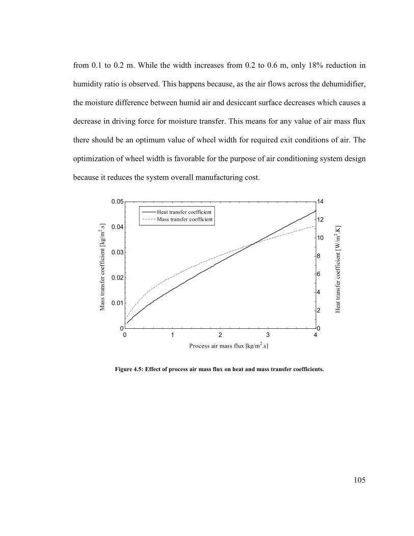
105
from 0.1 to 0.2 m. While the width increases from 0.2 to 0.6 m, only 18% reduction in
humidity ratio is observed. This happens because, as the air flows across the dehumidifier,
the moisture difference between humid air and desiccant surface decreases which causes a
decrease in driving force for moisture transfer. This means for any value of air mass flux
there should be an optimum value of wheel width for required exit conditions of air. The
optimization of wheel width is favorable for the purpose of air conditioning system design
because it reduces the system overall manufacturing cost.
Figure 4.5: Effect of process air mass flux on heat and mass transfer coefficients.
0 1 2 3 4
0
0.01
0.02
0.03
0.04
0.05
0
2
4
6
8
10
12
14
Process air mass flux [kg/m2.s]
Mas
s tr
ansf
er c
oeff
icie
nt [
kg/m
2 .s]
Hea
t tra
nsfe
r co
effi
cien
t [W
/m2 .K
]
Heat transfer coefficientHeat transfer coefficientMass transfer coefficientMass transfer coefficient
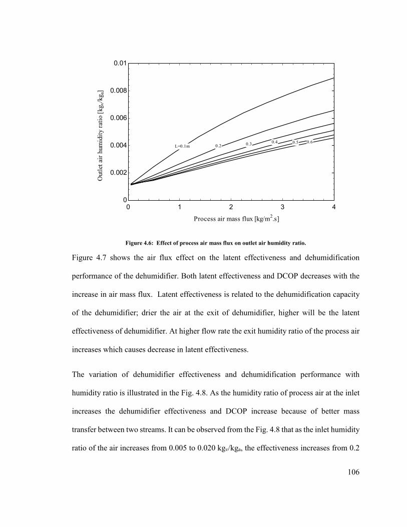
106
Figure 4.6: Effect of process air mass flux on outlet air humidity ratio.
Figure 4.7 shows the air flux effect on the latent effectiveness and dehumidification
performance of the dehumidifier. Both latent effectiveness and DCOP decreases with the
increase in air mass flux. Latent effectiveness is related to the dehumidification capacity
of the dehumidifier; drier the air at the exit of dehumidifier, higher will be the latent
effectiveness of dehumidifier. At higher flow rate the exit humidity ratio of the process air
increases which causes decrease in latent effectiveness.
The variation of dehumidifier effectiveness and dehumidification performance with
humidity ratio is illustrated in the Fig. 4.8. As the humidity ratio of process air at the inlet
increases the dehumidifier effectiveness and DCOP increase because of better mass
transfer between two streams. It can be observed from the Fig. 4.8 that as the inlet humidity
ratio of the air increases from 0.005 to 0.020 kgv/kga, the effectiveness increases from 0.2
0 1 2 3 4
0
0.002
0.004
0.006
0.008
0.01
Process air mass flux [kg/m2.s]
Out
let a
ir h
umid
ity
rati
o [k
g v/k
g a]
L=0.1m 0.2 0.3 0.4 0.5 0.6

107
to 0.7 but after 0.020 kgv/kga, there is very small change in effectiveness, which means the
increasing of absolute moisture removal is not as significant as the increasing of ωa,in under
the simulated condition. In fact, increasing the air inlet humidity ratio causes an increase
in the driving force and hence increases the mass transfer potential within the dehumidifier.
Consequently, the desiccant dehumidifier can obtain a better effectiveness and high DCOP
with higher ωa,in. The partial vapor pressure is the governing factor for the mass transfer
between process air and desiccant surface. As the inlet air humidity ratio increases, the
partial pressure of water vapor in the air also increases which in turn enhances the
difference between the partial vapor pressure in the inlet air stream and on the desiccant
surface resulting an increase in the moisture absorbing capacity of desiccant.
Figure 4.7: Effect of process air flux on the latent effectiveness and DCOP.
0 1 2 3 4 5 6
0.5
0.6
0.7
0.8
0.45
0.5
0.55
0.6
Process air mass flux [kg/m2.s]
Lat
ent e
ffec
tive
ness
[-]
DC
OP
[-]
Latent effectiveness
DCOP

108
Figure 4.8: Effect of inlet air humidity ratio on the latent effectiveness and DCOP.
The variation of DCOP with rotational speed of the wheel at different regeneration
temperatures is presented in Fig. 4.9. The DCOP decreases with the increase in rotational
speed because of less contact time between humid air and desiccant surface. The
occurrence of the maximum DCOP at a low rotational speed is expected. If the rotational
speed is too high the desiccant cannot fully absorb or desorb water molecules because of
the less process time. Since the main purpose of the desiccant dehumidifier is to remove
moisture rather than exchanging heat, the rotational speed that yields the maximum DCOP
is recommended. Figure 4.9 also shows the strong dependence of DCOP on the
regeneration temperature. As the regeneration temperature increases, DCOP for latent
cooling decreases. Although the higher value of regeneration temperature will make the
moisture removal process faster but at the same time this higher value of temperature will
dry-up the desiccant wheel before the completion of regeneration period. Hence, some
0.005 0.01 0.015 0.02 0.025
0.1
0.2
0.3
0.4
0.5
0.6
0.7
0.8
0
0.2
0.4
0.6
0.8
1
1.2
Inlet air humidity ratio [kgv/kga]
Lat
ent e
ffec
tive
ness
[-]
DC
OP
[-]
Latent effectiveness
DCOP

109
added energy will be wasted and will not be utilized during absorption period for moisture
removal. Secondly, the higher value of regeneration temperature will increase the input
energy which decreases the DCOP of the cycle. A low regeneration temperature enhances
the potential of these systems to use in solar application.
The other parameter which affect the DCOP of the system is ratio of regeneration to process
air flow rate. The DCOP increases as this ratio decreases as shown in Fig. 4.10. The
increase in DCOP with decrease in this ratio of air flow rates occurs because of decrease
in required regeneration heat. As the ratio of air flow rates or flow rate of regeneration air
decreases, required heat of regeneration decreases. The removal of moisture from the air
decreases with the increase in speed of the wheel as shown in Fig 4.11. As the wheel speed
increases the contact time between air and desiccant decreases, the removal of moisture
from the air decreases.
Figure 4.9: Effect of rotational speed on DCOP for different regeneration temperatures.
1 2 3 4 5 6
0
0.2
0.4
0.6
0.8
1
Rotational speed [rpm]
DC
OP
[-]
Regeneration Temperature [oC]
9090
8080
7070
6060

110
Figure 4.10: Effect of rotational speed on DCOP for different mass flow rate ratios.
Figure 4.11: Effect of rotational speed on dehumidifier moisture removal capacity for different process air mass flow rate.
1 2 3 4 5 6 7
0.2
0.4
0.6
0.8
Rotational speed [rpm]
DC
OP
[-]
mr/mp
110.80.8
0.60.60.40.4
0.250.25
1 2 3 4 5 6 7
0
0.01
0.02
0.03
0.04
0.05
0.06
Rotational Speed [rpm]
Moi
stur
e re
mov
al r
ate
[kg/
s]
Process air mass flux [kg/m2.s]
22
33
44
55
x10-1
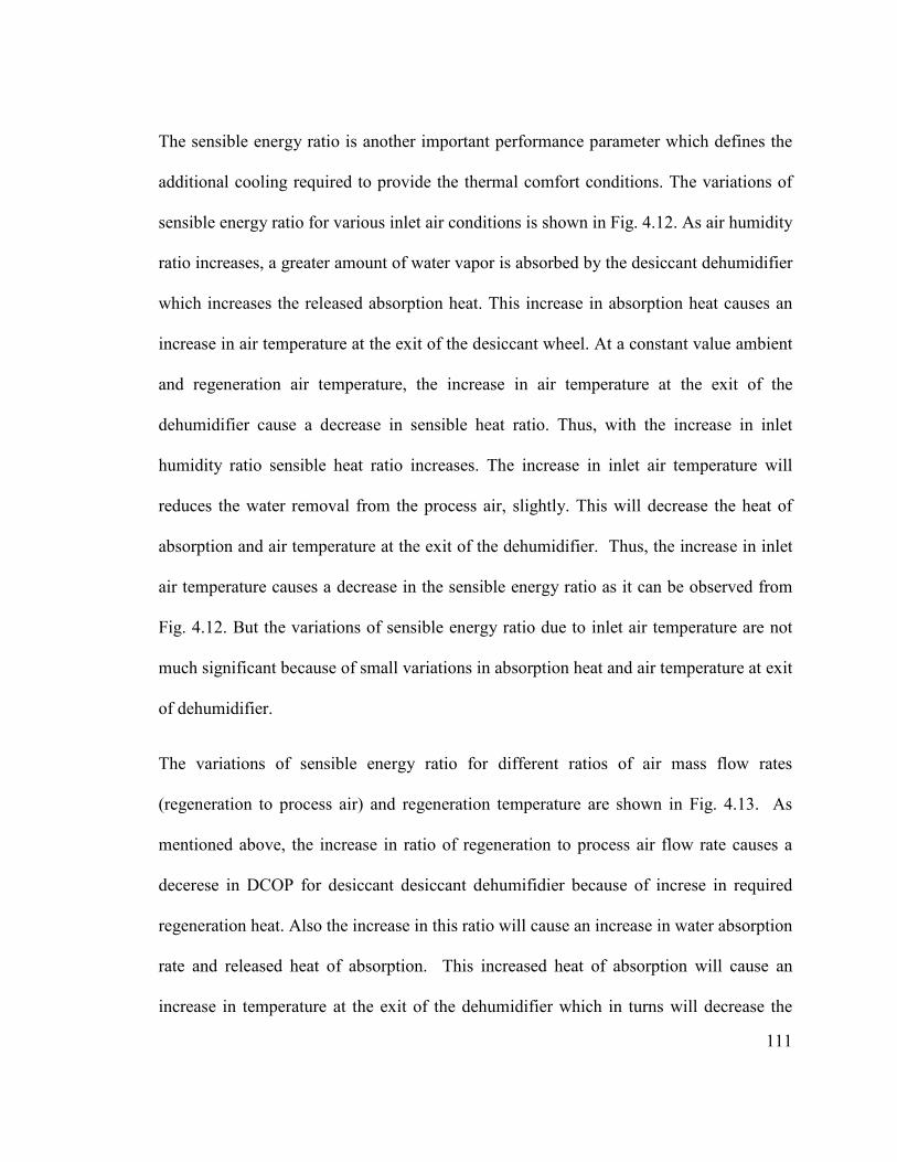
111
The sensible energy ratio is another important performance parameter which defines the
additional cooling required to provide the thermal comfort conditions. The variations of
sensible energy ratio for various inlet air conditions is shown in Fig. 4.12. As air humidity
ratio increases, a greater amount of water vapor is absorbed by the desiccant dehumidifier
which increases the released absorption heat. This increase in absorption heat causes an
increase in air temperature at the exit of the desiccant wheel. At a constant value ambient
and regeneration air temperature, the increase in air temperature at the exit of the
dehumidifier cause a decrease in sensible heat ratio. Thus, with the increase in inlet
humidity ratio sensible heat ratio increases. The increase in inlet air temperature will
reduces the water removal from the process air, slightly. This will decrease the heat of
absorption and air temperature at the exit of the dehumidifier. Thus, the increase in inlet
air temperature causes a decrease in the sensible energy ratio as it can be observed from
Fig. 4.12. But the variations of sensible energy ratio due to inlet air temperature are not
much significant because of small variations in absorption heat and air temperature at exit
of dehumidifier.
The variations of sensible energy ratio for different ratios of air mass flow rates
(regeneration to process air) and regeneration temperature are shown in Fig. 4.13. As
mentioned above, the increase in ratio of regeneration to process air flow rate causes a
decerese in DCOP for desiccant desiccant dehumifidier because of increse in required
regeneration heat. Also the increase in this ratio will cause an increase in water absorption
rate and released heat of absorption. This increased heat of absorption will cause an
increase in temperature at the exit of the dehumidifier which in turns will decrease the

112
sensible heat ratio. Thus, with the increase in ratio between regeneration and process air
flow rates, a reduction in sensible energy ratio occurs. The increase in regeneration
temperature will also cause a decrease in sensible energy ratio because of increase in
required heat input.
Figure 4.12: Effect of inlet air conditions on sensible energy ratio for different ambient air temperatures.
x 103
0.01 0.015 0.02 0.025
0.1
0.2
0.3
0.4
0.5
0.6
Inlet process air humidity ratio [kgv/kga]
Sens
ible
ene
rgy
rati
o [-
]
Ambient Temperature [oC]
30
35
40
113
Figure 4.13: Effect of mass flow rates ratio on sensible energy ratio for different regeneration temperatures.
4.6 Conclusions
A theoretical model for the liquid desiccant dehumidifier is developed to observe the heat
and mass transfer phenomenon for absorption and desorption process under different
operating parameters like process air flow rate, humidity ratio of process air, and width of
the dehumidifier. Effect of these parameters also been observed on dehumidifier
effectiveness, moisture removal rate and DCOP. The computed results show that supply
air condition can be obtained to provide human comfort in the hot and humid climate with
effectiveness of the system largely dependent on air flow rate, dehumidifier width and
humidity ratio of process air. For better performance of the desiccant cooling system the
regeneration heat required should be as minimum as possible. The regeneration heat
depends on the regeneration air flow rate, an optimum and feasible value of the
0 0.2 0.4 0.6 0.8 1 1.2
0
0.2
0.4
0.6
0.8
1
mr/mp
Sens
ible
ene
rgy
rati
o [-
]
Regeneration Temperature [oC]
9080
70
60
55
114
regeneration air flow rate can be obtained by the parametric analysis in the required zone
of operation.
Different performance curves of the desiccant dehumidifier have been drawn in order to
determine optimum values of different parameters. The result shows that there is an
optimum value of each design parameter under each operating condition and above that
value, there is very little change in the performance of desiccant dehumidifier. The main
conclusions emerging from the present work can be summarized as:
• The dehumidification performance of the desiccant wheel increase with the
increase in process air inlet humidity ratio because of better mass transfer between
two streams.
• Increasing the wheel width leads to better dehumidification of process air; however,
the dehumidification rate is decreased because of reduction in moisture difference
between humid air and desiccant surface. The reduction of about 30% in humidity
ratio is observed with an increase in the wheel width from 0.1 to 0.2 m. While the
width increases from 0.2 to 0.6 m, only 18% reduction in humidity ratio is observed.
• The COP of the system is high at lower rotational speed because of the more process
time for absorption and desorption of moisture.
• As the regeneration temperature or flow rate of regeneration air increases, COP for
latent cooling decreases due to high required heat input.

115
• The exergy efficiency of the system increases with the increase in ambient air
temperature and decreases with the increase in regeneration temperature, ambient
air humidity ratio, and ratio of mass flow rates.
• The feasibility analysis shows that the system can operate with a good
dehumidification capacity through the whole year. The average value of DCOP for
the year is found to be 0.55 which shows that system can control the latent load
efficiently throughout the whole year. The maximum value of DCOP of about 0.7
was obtained for May and September and minimum of about 0.2 for January.
For better coefficient of the performance of the overall system the desiccant material should
have lower temperature of regeneration which is a key factor for future research.
116
5 CHAPTER 5
EXPERIMENTAL INVESTIGATION OF LIQUID
DESICCANT COOLING CYCLE
5.1 Introduction
The simultaneous control of temperature and humidity of air is required to provide the
human comfort conditions. The conventional air conditioning system cools the air below
its dew point temperature to remove the moisture from air. In hot and humid regions,
considerable amount of load is used to remove the moisture from the air using these
conventional vapor compression refrigeration systems. Because of the high energy cost of
these conventional systems and poor control of latent load in hot and humid conditions,
need arises for some alternative cooling system. Desiccant cooling is found to be an
alternative to vapor compression refrigeration for applications of space cooling. It is
beneficial for environment and also cost effective since no refrigerant is required which
can deplete the ozone layer. Low temperature heat sources, like waste heat from engine or
solar heat, can be used to operate the system.
Desiccant cooling is a thermal technique based on air dehumidification followed by
evaporative cooling. This technology is a good alternative for conventional vapor
compression systems to meet new economic, environmental, and regulatory challenges.
The major component of a desiccant cooling system is desiccant dehumidifier which is
used to control the latent load by the dehumidification of the humid air. The desiccant
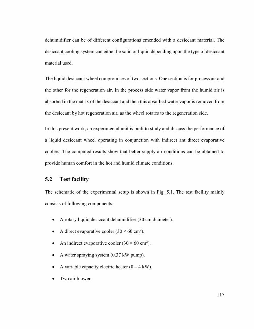
117
dehumidifier can be of different configurations emended with a desiccant material. The
desiccant cooling system can either be solid or liquid depending upon the type of desiccant
material used.
The liquid desiccant wheel compromises of two sections. One section is for process air and
the other for the regeneration air. In the process side water vapor from the humid air is
absorbed in the matrix of the desiccant and then this absorbed water vapor is removed from
the desiccant by hot regeneration air, as the wheel rotates to the regeneration side.
In this present work, an experimental unit is built to study and discuss the performance of
a liquid desiccant wheel operating in conjunction with indirect ant direct evaporative
coolers. The computed results show that better supply air conditions can be obtained to
provide human comfort in the hot and humid climate conditions.
5.2 Test facility
The schematic of the experimental setup is shown in Fig. 5.1. The test facility mainly
consists of following components:
• A rotary liquid desiccant dehumidifier (30 cm diameter).
• A direct evaporative cooler (30 × 60 cm2).
• An indirect evaporative cooler (30 × 60 cm2).
• A water spraying system (0.37 kW pump).
• A variable capacity electric heater (0 – 4 kW).
• Two air blower
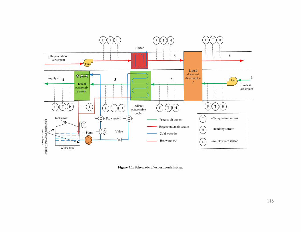
118
Figure 5.1: Schematic of experimental setup.
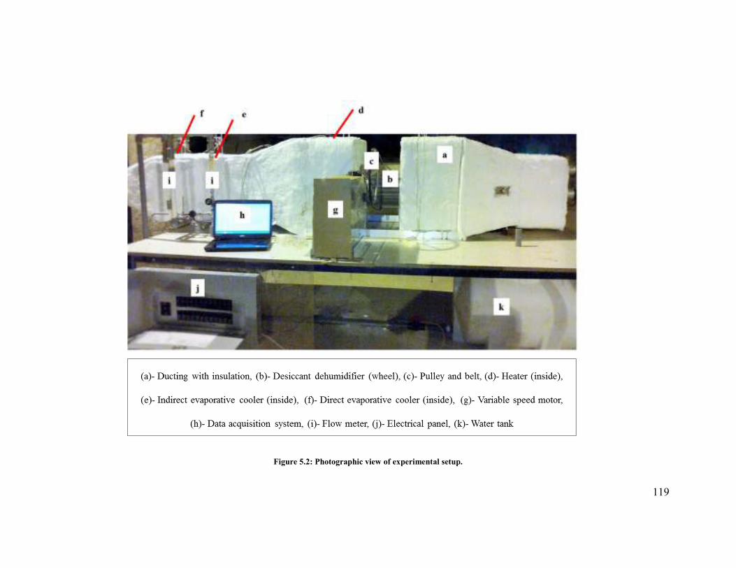
119
Figure 5.2: Photographic view of experimental setup.

120
The details of all other supporting and operation facilities are shown in Fig. 5.2. The
rotating desiccant wheel shown in Fig. 5.3(a) has a cylindrical shape of 30 cm diameter is
fabricated from flexi glass. Flow area is created using pipes of Chlorinated polyvinyl
chloride of diameter 21 mm with minimum spacing between two pipes. These pipes are
uniformly distributed over the cross section of the wheel. To form the absorbing surface, a
thick cloth layer impregnated with the calcium chloride solution is placed inside the pipes
using springs. The variable speed motor is used to vary the rotational speed of the desiccant
wheel. The regeneration heat is provided using a variable capacity electric heater. In the
process air stream, after the desiccant dehumidifier direct and indirect evaporative coolers
are used for cooling purpose. With direct evaporative cooling, outside air is blown through
a water saturated medium and cooled by evaporation. The packing material for the used
direct evaporative cooler is composed of cellulose pad. The size of the pad is 15 cm deep
30 cm wide and 60 cm high. The water is distributed using spray nozzles at the top of
cooling pads. While in indirect evaporative cooler, cooling water circulates inside the coils
and air cools as it passes across the tubes. The indirect evaporative cooler coils are
constructed from copper tubes with bonded aluminum fins. Fins are attached to the outside
of tubes to enhance the surface area for heat transfer. The coils have an anti-corrosion
coating such as blue fin coating for extra protection and longer life. The detailed working
principle for both types of evaporative coolers have already been discussed in Chapter 2.
The photographic views of direct and indirect evaporative cooler used in this work have
been shown in Fig 5.3(b and c), respectively.

121
Two air dampers are used to vary the flow rates of process and regeneration air. The 25%
face area of the wheel is for the regeneration stream of the air and remaining 75% area is
for the process air stream.
The two streams of air flow in the counter flow direction as shown in Fig. 5.1. For the
process air stream, humid air passes through the desiccant wheel and moisture from the air
is absorbed by the liquid desiccant (1 – 2). This dehumidified air is first passed through an
indirect evaporative cooler (2 – 3) and then direct evaporative cooler (3 – 4) to lower its
temperature according to supply demands. The ambient air on the regeneration side is
passed through the electric heater to bring it to the desired temperature for reactivation of
desiccant wheel (1 – 5). The high temperature air then enters the wheel and moisture is
removed from the desiccant (5 – 6). The complete desiccant cooling cycle is represented
on psychrometric chart in Fig. 5.4.
(a) (b) (c)
Figure 5.3: (a) Desiccant wheel; (b) direct evaporative cooler; (c) indirect evaporative cooler.

122
Dry bulb temperature (oC)
Hum
idity
rat
io (k
g/kg
of d
ry
air)
DB
1
2
4
5
6
3
Figure 5.4: Psychrometric representation of desiccant cooling cycle.
5.3 Desiccant preparation
The concentration of calcium chloride was obtained experimentally using a simple
procedure which can be described as follow: A solution was prepared in a close container
using a known mass of water and CaCl2 flakes. The solution was covered and placed in an
environment with temperature around 25 – 30oC for 48 hours. The solution was filtered to
remove any impurities. Then, the specific gravity and temperature of the solution were
measured simultaneously and desiccant concentration was determined using CaCl2
handbook [235].
5.4 Instrumentations
Temperature of the process and regeneration air at all the state points are measured using
k-type thermocouples as shown in Fig. 5.1. A digital hygrometer and digital anemometer
were used to measure humidity and velocity of the air, respectively at different points. All

123
properties obtained such as temperatures and RHs were used to evaluate the psychrometric
properties including humidity ratio and enthalpy. The power consumption of the electric
heater was measured with digital watt meters. The details of all the sensors are provided in
Table 5.1 and they were calibrated under testing conditions.
Table 5.1: Specifications of sensors.
Parameters Devices Model no. Accuracy
Air temperature K-type thermocouple
KK-K-30 ±0.2oC
@23±5oC
Air relative humidity
Hygrometer RHXL3SD For ≥ 70% RH
±(3%+ 1% RH) For < 70% RH
± 3% RH
Air flow rate Anemometer HHF1001A 1.5% Full scale accuracy
Heater capacity Watt meter GH-019D ± (0.2% reading + 0.05% FS)
Desiccant density Hydrometer - 1 kg/m3
5.5 Test procedure and conditions
The data acquisition system was established which control the relative humidity,
temperature, and mass flow can rate of all state points shown in Fig. 5.1. Both blowers and
desiccant wheel motor were turned on. Once the desired air conditions were reached, the
electric heater was turned on to obtain the desired regeneration temperature. After steady
state conditions had been achieved, data were recorded with a specified time interval.
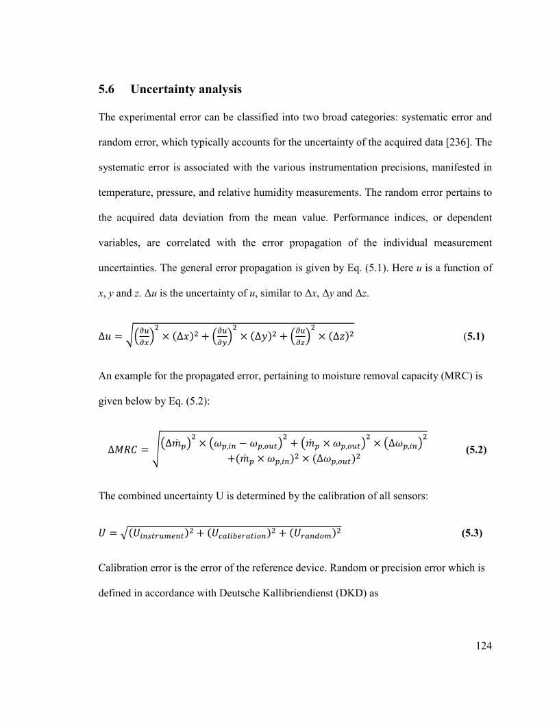
124
5.6 Uncertainty analysis
The experimental error can be classified into two broad categories: systematic error and
random error, which typically accounts for the uncertainty of the acquired data [236]. The
systematic error is associated with the various instrumentation precisions, manifested in
temperature, pressure, and relative humidity measurements. The random error pertains to
the acquired data deviation from the mean value. Performance indices, or dependent
variables, are correlated with the error propagation of the individual measurement
uncertainties. The general error propagation is given by Eq. (5.1). Here u is a function of
x, y and z. ∆u is the uncertainty of u, similar to ∆x, ∆y and ∆z.
∆d = efgOghi� × (∆j)� + fgOgli� × (∆m)� + fgOgni� × (∆o)� (5.1)
An example for the propagated error, pertaining to moisture removal capacity (MRC) is
given below by Eq. (5.2):
∆=aT = pq∆�� >r� × qA>,Ds − A>,FOr� + q�� > × A>,FOr� × q∆A>,Dsr�+(�� > × A>,Ds)� × (∆A>,FO)� (5.2)
The combined uncertainty U is determined by the calibration of all sensors:
t = u(tDsv�OWQs)� + (t�BRDwQ�BDFs)� + (t�BsPFW)� (5.3)
Calibration error is the error of the reference device. Random or precision error which is
defined in accordance with Deutsche Kallibriendienst (DKD) as

125
t�BsPFW = xy,z{%}u~� (5.4)
Where,
� = N-1 (5.5)
Illustration for calculation: A standard platinum resistance thermometer (Type PT25)
with an uncertainty of 2.0-4.0 mK in the temperature range of 0-120°C, is used for the
calibration of K-type thermocouple. Both the thermocouple and PT25 are placed in
thermostat with an immersed copper block calibrator for calibration. An uncertainty in the
range of 0.10 - 0.25 K is realized for all thermocouples used in this work. This range is
equivalent to 0.5-1.0% for the temperature range of 20-70°C; where 20°C is the average
room temperature during the measurement and 85°C is the maximum regeneration
temperature used in this work. The calculated uncertainties for different instrumentations
are listed in Table 5.2.
Table 5.2: Uncertainties of measuring instruments used in experiment.
Instrument Parameter Uncertainty
K-type thermocouple Temperature ± 0.1oC
Anemometer Velocity of air ± 0.1m/s
Density meter (hydrometer) Desiccant density ± 1 kg/m3
Electronic weighing machine Desiccant mass ± 0.001 kg
Rota meter Water flow rate ± 0.5 L/min

126
5.7 Performance parameters
The rate of moisture removal from the process air by the liquid desiccant cooling system
is defined as moisture removal rate (Mr).
=� = �� >(A� − A�) (5.6)
Note that all the state points refers to Fig. 5.1.
Dehumidification coefficient of performance (DCOP) is another parameter used to
represent the desiccant dehumidifier capacity to dehumidify the air. For the different mass
flow rates of process and regeneration air, DCOP is given as:
STUV = W� X×YZ[×(G�JG�)W� \×(Y�JY�) (5.7)
A higher DCOP indicates a better system performance because the energy input to the
regeneration air is utilized in a better way or less heat is being used to heat up the desiccant.
The sensible energy ratio (SER) is also used when evaluating the desiccant dehumidifier.
The SER can quantify additional sensible load to be handled by some additional cooling
mechanism at the downstream such as an evaporative cooler. The SER is given by:
_`a = W� X×(Y�JY�)W� \× (Y�JY �) (5.8)
For better dehumidification performance of the desiccant wheel the value of SER should
be lower. The higher value of SER means more cooling load on the cooling device because
of higher temperature of process air at the outlet of desiccant wheel. Lower values of SER

127
mean that the desiccant dehumidifier is creating a lower sensible cooling load, which
indicates better performance of the system.
The overall cooling provided by the desiccant system is defined as cooling capacity. The
difference of enthalpy between outdoor and supply air is used to represent overall cooling
capacity because it includes both sensible and latent loads.
T������ �������m (TT) = �� > (ℎ� − ℎ�) (5.9)
The overall performance of the system is represented by coefficient of performance (COP).
TUV = �����M\]HN+(��KKN��X�]XI�[)�
(5.10)
where, � equivalent conversion coefficient of electric power and thermal energy and its
value is taken as 0.3 [131].
The ratio between the CC and electrical energy consumption is given by electrical
coefficient of performance (ECOP) while ratio between CC to consumption of thermal
energy is represented by thermal coefficient of performance (TCOP).
ETUV = ����KKN+�X�]XI�[ (5.11)
TTUV = �����M\]HN (5.12)
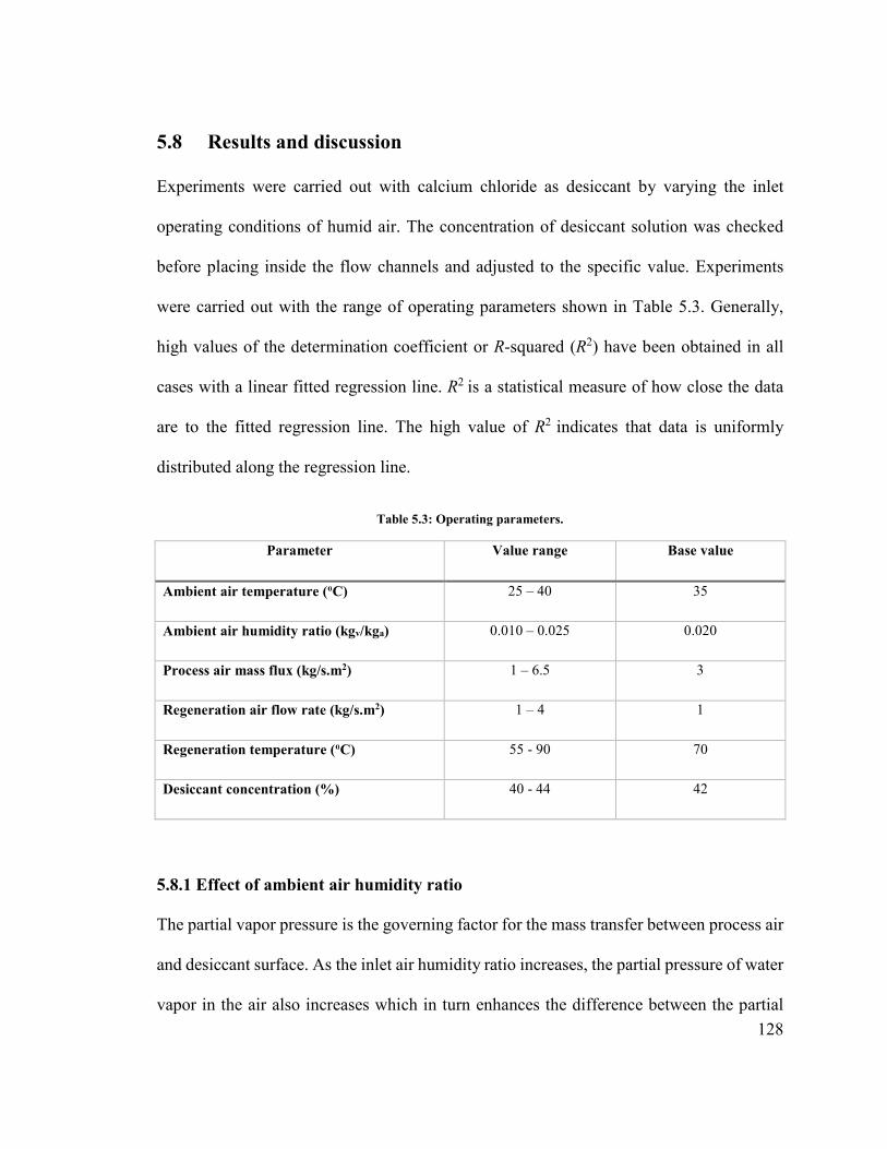
128
5.8 Results and discussion
Experiments were carried out with calcium chloride as desiccant by varying the inlet
operating conditions of humid air. The concentration of desiccant solution was checked
before placing inside the flow channels and adjusted to the specific value. Experiments
were carried out with the range of operating parameters shown in Table 5.3. Generally,
high values of the determination coefficient or R-squared (R2) have been obtained in all
cases with a linear fitted regression line. R2 is a statistical measure of how close the data
are to the fitted regression line. The high value of R2 indicates that data is uniformly
distributed along the regression line.
Table 5.3: Operating parameters.
Parameter Value range Base value
Ambient air temperature (oC) 25 – 40 35
Ambient air humidity ratio (kgv/kga) 0.010 – 0.025 0.020
Process air mass flux (kg/s.m2) 1 – 6.5 3
Regeneration air flow rate (kg/s.m2) 1 – 4 1
Regeneration temperature (oC) 55 - 90 70
Desiccant concentration (%) 40 - 44 42
5.8.1 Effect of ambient air humidity ratio
The partial vapor pressure is the governing factor for the mass transfer between process air
and desiccant surface. As the inlet air humidity ratio increases, the partial pressure of water
vapor in the air also increases which in turn enhances the difference between the partial

129
vapor pressure in the inlet air stream and on the desiccant surface resulting an increase in
the moisture absorbing capacity of desiccant. The effect of the process air inlet humidity
was investigated as shown in Fig. 5.5. The overall performance (COP), electrical
coefficient of performance (ECOP), and thermal coefficient of performance (TCOP) of the
system increases with the increase in inlet air humidity ratio as shown in Fig. 5.5(a, b, and
c). The increase in humidity ratio of the ambient air results in the increased potential for
mass transfer. Therefore, this increase in mass transfer enhances the capacity of the system
to remove the latent load from the conditioned space. Although, with the increase in
ambient air humidity required input heat will also increase for desorption of moisture but
this increase is not as high as capacity of the system to remove latent load. Thus, higher
the ambient air humidity, better will be the performance (COP, TCOP, and ECOP) of the
system.
Fig. 5.5(d) shows that moisture removal rate increases with the increase in inlet air
humidity ratio due to the increase in mass transfer potential. In fact, increasing the air inlet
humidity ratio causes an increase in the driving force and hence increases the mass transfer
potential within the dehumidifier. Increased humidity ratio indicates higher partial pressure
of water vapor, which means higher tendency for water to condense and be absorbed by
the desiccant material, thus larger driving force for absorption. Similar to moisture removal
rate, a higher dehumidification coefficient of performance (DCOP) was achieved at higher
inlet humidity ratio because of an increase in the moisture absorbing capacity of desiccant
dehumidifier as shown in Fig. 5.5(e). For instance, the moisture removal rate and DCOP

130
increased by 48 and 62%, respectively when the humidity ratio is increased from 0.01 to
0.025 kg/kg.
As regards to sensible energy ratio, the temperature at the exit of dehumidifier strongly
increases with humidity ratio of inlet air because of larger quantity of water vapor absorbed
by the desiccant. Therefore, temperature at state point 2 increases due to the increase in the
released heat of absorption. Thus, increase in humidity ratio of inlet air will increase the
sensible energy ratio of the system at fixed value of regeneration and supply air temperature
as shown in Fig. 5.5(f).
y = 17.367x + 0.1795R² = 0.9241
0
0.2
0.4
0.6
0.8
0.01 0.012 0.014 0.016 0.018 0.02 0.022 0.024 0.026 0.028
CO
P [
-]
Ambient humidity ratio [kg/kg]
(a)
COP [-] Linear (COP [-])
y = 109.78x + 1.1578R² = 0.8246
0
1
2
3
4
5
0.01 0.012 0.014 0.016 0.018 0.02 0.022 0.024 0.026 0.028
EC
OP
[-]
Ambient air humidity ratio [kg/kg]
(b)
ECOP [-] Linear (ECOP [-])
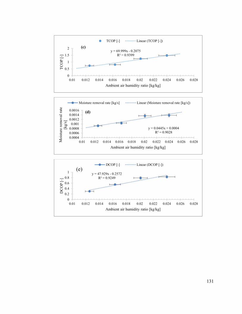
131
y = 69.999x - 0.2075R² = 0.9399
0
0.5
1
1.5
2
0.01 0.012 0.014 0.016 0.018 0.02 0.022 0.024 0.026 0.028
TC
OP
[-]
Ambient air humidity ratio [kg/kg]
(c)
TCOP [-] Linear (TCOP [-])
y = 0.0445x + 0.0004R² = 0.9028
0.00040.00060.0008
0.0010.00120.00140.0016
0.01 0.012 0.014 0.016 0.018 0.02 0.022 0.024 0.026 0.028Moi
stur
e re
mov
al r
ate
[kg/
s]
Ambient air humidity ratio [kg/kg]
(d)
Moisture removal rate [kg/s] Linear (Moisture removal rate [kg/s])
y = 47.929x - 0.2572R² = 0.9249
0
0.2
0.4
0.6
0.8
1
0.01 0.012 0.014 0.016 0.018 0.02 0.022 0.024 0.026 0.028
DC
OP
[-]
Ambient air humidity ratio [kg/kg]
(e)DCOP [-] Linear (DCOP [-])

132
Figure 5.5: Effect of ambient air humidity ratio on: (a) COP; (b) ECOP; (c) TCOP; (d) moisture removal rate; (e) DCOP; (f) sensible energy ratio.
5.8.2 Effect of ambient air temperature
The liquid desiccant cooling system should be equipped with a highly efficient control
system in order to have a better control of supply conditions according to outdoor and
indoor conditions.
The temperature of air at the exit of dehumidifier (state point 2) in Fig. 5.1 increases as the
temperature of the ambient air increases. This increase in difference of temperature,
increases the difference in enthalpy of air across the rotary dehumidifier. This increased
difference of enthalpy causes an increase in cooling capacity of the system. The achieved
improvement in the system performance (COP, ECOP, and TCOP) as shown in Fig. 5.6(a,
b, and c) is because of the fact that at higher ambient air temperature, the amount of heat
and mass transfer from the air to the desiccant will be enhanced. This enhancement of heat
and mass transfer will also increase the amount of heat released from the air to the desiccant
during the absorption process.
Figure 5.6(d) shows the impact of process air inlet temperature on the moisture removal
rate. There is a slight decrease in the moisture removal rate when the inlet air temperature
y = 8.9876x + 0.1518R² = 0.9874
0
0.1
0.2
0.3
0.4
0.5
0.01 0.012 0.014 0.016 0.018 0.02 0.022 0.024 0.026 0.028
Sen
sibl
e en
ergy
rat
io [
-]
Ambient air humidity ratio [kg/kg]
(f)
Sensible energy ratio [-] Linear (Sensible energy ratio [-])

133
is increased. This is due to the fact that the desiccant can be cooled adequately at the lower
temperature and hence leading to a high absorption capability. This may be explained as
follows: as the process air inlet temperature is increased, the temperature of the desiccant
inside the dehumidifier is increased along with the partial vapor pressure on the desiccant
surface. When the desiccant surface vapor pressure increases, the potential of the
absorption process is decreased causing air to become more humid and in turn low moisture
removal rate. When temperature of ambient air is increased from 25 to 45°C, the moisture
removal rate is decreased by about 15%.
DCOP as a function of outdoor air temperature has been shown in Fig. 5.6(e). As regards
to DCOP, the increase in process air inlet temperature causes a slight reduction of moisture
removal capacity, but there is an increase in inlet enthalpy; therefore the heat needed to
achieve a fixed regeneration temperature significantly reduces with inlet temperature, and
DCOP rises. As regards to sensible energy ratio, the Fig. 5.6(f) shows similar trends as the
increase in process air inlet temperature does not cause a significant change in SER.
y = 0.0187x - 0.0882R² = 0.9735
0
0.2
0.4
0.6
0.8
20 25 30 35 40 45
CO
P [
-]
Ambient air temperature [oC]
(a)
COP [-] Linear (COP [-])

134
y = 0.0835x + 0.8388R² = 0.9886
0
1
2
3
4
5
20 25 30 35 40 45
EC
OP
[-]
Ambient air temperature [oC]
(b)
ECOP [-] Linear (ECOP [-])
y = 0.0484x - 0.5484R² = 0.9573
0
0.5
1
1.5
2
20 25 30 35 40 45
TC
OP
[-]
Ambient air temperature [oC]
(c)
TCOP [-] Linear (TCOP [-])
y = -9E-06x + 0.0015R² = 0.7847
0
0.0005
0.001
0.0015
20 25 30 35 40 45Moi
stur
e re
mov
al r
ate
[kg/
s]
Ambient air temperature [oC]
(d)
Moisture removal rate [kg/s] Linear (Moisture removal rate [kg/s])
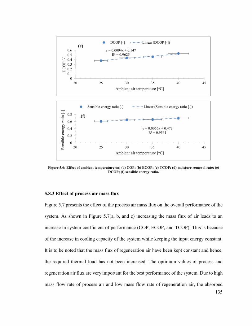
135
Figure 5.6: Effect of ambient temperature on: (a) COP; (b) ECOP; (c) TCOP; (d) moisture removal rate; (e) DCOP; (f) sensible energy ratio.
5.8.3 Effect of process air mass flux
Figure 5.7 presents the effect of the process air mass flux on the overall performance of the
system. As shown in Figure 5.7(a, b, and c) increasing the mass flux of air leads to an
increase in system coefficient of performance (COP, ECOP, and TCOP). This is because
of the increase in cooling capacity of the system while keeping the input energy constant.
It is to be noted that the mass flux of regeneration air have been kept constant and hence,
the required thermal load has not been increased. The optimum values of process and
regeneration air flux are very important for the best performance of the system. Due to high
mass flow rate of process air and low mass flow rate of regeneration air, the absorbed
y = 0.0094x + 0.147R² = 0.9625
00.10.20.30.40.50.6
20 25 30 35 40 45
DC
OP
[-]
Ambient air temperature [oC]
(e)DCOP [-] Linear (DCOP [-])
y = 0.0056x + 0.473R² = 0.9561
0
0.2
0.4
0.6
0.8
20 25 30 35 40 45Sen
sibl
e en
ergy
rat
io [
-]
Ambient air temperature [oC]
(f)
Sensible energy ratio [-] Linear (Sensible energy ratio [-])
136
moisture will not be efficiently removed from the dehumidifier. Similarly, at low flow rate
of process air and high flow rate of regeneration air, the required heat input will be
increased to high level as compared to cooling capacity and it can also dry the desiccant
before the regeneration process is being completed.
Variations of the moisture removal rate and DCOP with the process air mass flux are
plotted in Fig. 5.7(d and e). The moisture removal rate increases with the increase in
process air mass flux because of the increase in driving force for moisture transfer.
However, the total moisture removal capacity decreases due less residence time at higher
flow rates. Thus, DCOP decreases with mass flux of process air as illustrated in Fig. 5.7(e).
As increasing the inlet flow rate of process air leads to an increase in both the supply air
humidity ratio and temperature inside the dehumidifier. Thus, keeping the regeneration
temperature constant, sensible energy ratio will increase with inlet process air mass flux as
shown in Fig. 5.7(f). This is basically due to the larger amount of air introduced to the
dehumidification unit and thus the capability of the dehumidifier to reduce the humidity of
the air decreases.
y = 0.0592x + 0.0543R² = 0.9702
00.10.20.30.40.50.6
0.5 1.5 2.5 3.5 4.5 5.5 6.5
CO
P [
-]
Process air mass flux [kg/s.m2]
(a)
COP [-] Linear (COP [-])
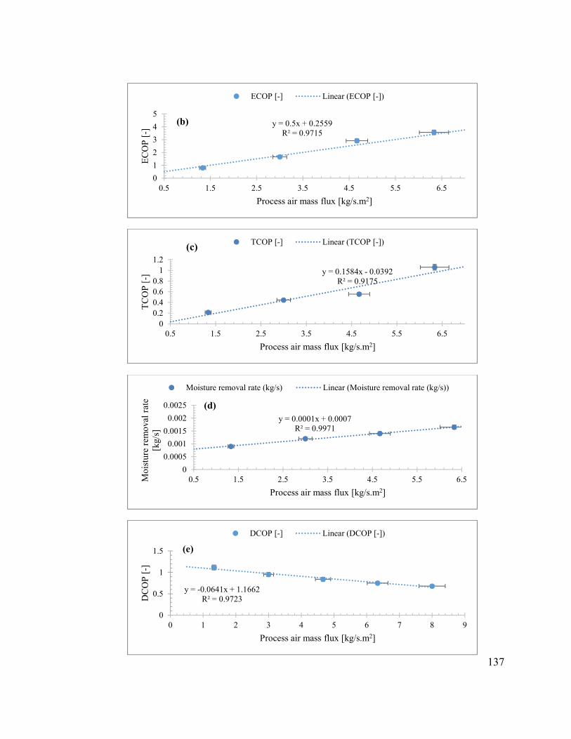
137
y = 0.5x + 0.2559R² = 0.9715
0
1
2
3
4
5
0.5 1.5 2.5 3.5 4.5 5.5 6.5
EC
OP
[-]
Process air mass flux [kg/s.m2]
(b)
ECOP [-] Linear (ECOP [-])
y = 0.1584x - 0.0392R² = 0.9175
00.20.40.60.8
11.2
0.5 1.5 2.5 3.5 4.5 5.5 6.5
TC
OP
[-]
Process air mass flux [kg/s.m2]
(c) TCOP [-] Linear (TCOP [-])
y = 0.0001x + 0.0007R² = 0.9971
0
0.0005
0.001
0.0015
0.002
0.0025
0.5 1.5 2.5 3.5 4.5 5.5 6.5Moi
stur
e re
mov
al r
ate
[kg/
s]
Process air mass flux [kg/s.m2]
(d)
Moisture removal rate (kg/s) Linear (Moisture removal rate (kg/s))
y = -0.0641x + 1.1662R² = 0.9723
0
0.5
1
1.5
0 1 2 3 4 5 6 7 8 9
DC
OP
[-]
Process air mass flux [kg/s.m2]
(e)
DCOP [-] Linear (DCOP [-])

138
Figure 5.7: Effect of process air mass flux on: (a) COP; (b) ECOP; (c) TCOP; (d) moisture removal rate; (e) DCOP; (f) sensible energy ratio.
5.8.4 Effect of regeneration air mass flux
The flow rate of regeneration air and regeneration temperature have a strong impact on the
performance of desiccant cooling system. The performance improvement of the system is
expected at lower regeneration temperature and mass flow rate of regeneration air since
both of these factors have direct effect on required input thermal energy.
The influence of regeneration air flow rates on performance of the system is shown in Fig.
5.8. In this case the value of process air flow rate is kept constant at the base value shown
in Table 5.3 while mass flow rate of regeneration air is varied. The COP and TCOP
decreases by 25 and 60%, respectively with the regeneration air flow rate increasing from
1.5 to 5 kg/m2.s as shown in Fig. 5.8(a and b). This may be explained as follows: when
flow rate of regeneration air increases, the input energy for regeneration will increase
which causes a decrease in the performance of the system. Consequently, more thermal
energy is consumed to condition the regeneration air to the specified temperature before
entering the regeneration portion. In Fig. 5.8(c and d), DCOP and SER as a function
y = 0.0444x + 0.0748R² = 0.8748
0
0.1
0.2
0.3
0.4
0.5
0.5 1.5 2.5 3.5 4.5 5.5 6.5Sen
sibl
e en
ergy
rat
io [
-]
Process air mass flux [kg/s.m2]
(f)
Sensible energy ratio [-] Linear (Sensible energy ratio [-])

139
regeneration air mass flow rate are shown. The increase in mass flow rate of regeneration
air causes a reduction in DCOP and it is due to a proportional rise in energy required for
regeneration. As regards to SER, the increase in regeneration air flow rate determines a
rise in absorbed moisture and heat of absorption. This causes an increase in process air
outlet temperature at the exit of desiccant wheel. Thus, SER decrease with the increase in
mass flow rate of regeneration air as shown in Fig. 5.8(d).
y = -0.0865x + 0.9506R² = 0.9641
0
0.2
0.4
0.6
0.8
1
1 1.5 2 2.5 3 3.5 4 4.5
CO
P [
-]
Regeneration air mass flux [kg/s.m2]
(a)
COP [-] Linear (COP [-])
y = -0.751x + 4.0852R² = 0.9205
0
1
2
3
4
1 1.5 2 2.5 3 3.5 4 4.5
TC
OP
[-]
Regeneration air mass flux [kg/s.m2]
(b)
TCOP [-] Linear (TCOP [-])
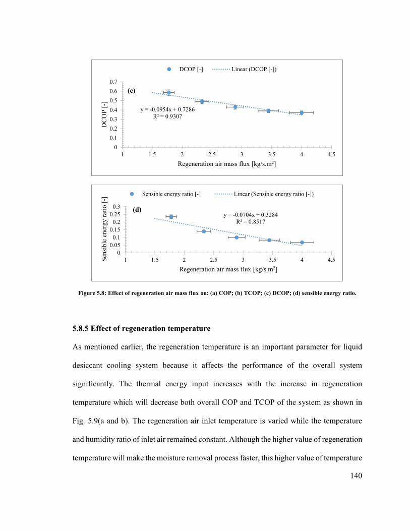
140
Figure 5.8: Effect of regeneration air mass flux on: (a) COP; (b) TCOP; (c) DCOP; (d) sensible energy ratio.
5.8.5 Effect of regeneration temperature
As mentioned earlier, the regeneration temperature is an important parameter for liquid
desiccant cooling system because it affects the performance of the overall system
significantly. The thermal energy input increases with the increase in regeneration
temperature which will decrease both overall COP and TCOP of the system as shown in
Fig. 5.9(a and b). The regeneration air inlet temperature is varied while the temperature
and humidity ratio of inlet air remained constant. Although the higher value of regeneration
temperature will make the moisture removal process faster, this higher value of temperature
y = -0.0954x + 0.7286R² = 0.9307
0
0.1
0.2
0.3
0.4
0.5
0.6
0.7
1 1.5 2 2.5 3 3.5 4 4.5
DC
OP
[-]
Regeneration air mass flux [kg/s.m2]
(c)
DCOP [-] Linear (DCOP [-])
y = -0.0704x + 0.3284R² = 0.8517
00.050.1
0.150.2
0.250.3
1 1.5 2 2.5 3 3.5 4 4.5Sen
sibl
e en
ergy
rat
io [
-]
Regeneration air mass flux [kg/s.m2]
(d)
Sensible energy ratio [-] Linear (Sensible energy ratio [-])

141
will dry up the desiccant inside the dehumidifier before the completion of regeneration
period. Hence, some added energy will be wasted and will not be utilized during absorption
period for moisture removal. Secondly, the higher value of regeneration temperature will
increase the input energy which decreases the COP of the cycle. The COP and TCOP of
the system decreases from 0.91 to 0.58 and 3.4 to 1, respectively, when regeneration
temperature increases from 50 to 85oC.
The moisture removal rate as well as DCOP of the desiccant dehumidifier has been plotted
as a function of regeneration temperature in Fig. 5.9(c and d), which shows that the
moisture removal capacity increases with regeneration temperature, whereas DCOP
decreases with an increase in regeneration temperature. In terms of DCOP, the increase in
moisture removal at higher regeneration temperature is not enough to balance the rise in
the input thermal energy per unitary mass flow rate. Hence, DCOP decreases with an
increasing regeneration temperature.
The sensible energy ratio is decreased with the increase in regeneration temperature as
shown in Fig. 5.9(e). This decrease of SER is because of increase in difference between
regeneration and process air inlet temperatures. In terms of thermal performances of the
wheel, the rise in process air temperature at outlet of dehumidifier with regeneration
temperature is because of the increased heating of the desiccant material in the regeneration
section and consequently in the process section when the dehumidifier rotates from the
former to the latter; but the increase in regeneration temperature itself causes a reduction
of SER, as expected from Eq. (5.8).

142
y = -0.0092x + 1.3344R² = 0.9355
00.20.40.60.8
1
45 50 55 60 65 70 75 80 85 90
CO
P [
-]
Regeneration temperature [oC]
(a)COP [-] Linear (COP [-])
y = -0.044x + 4.6575R² = 0.9534
0
1
2
3
45 50 55 60 65 70 75 80 85 90
TC
OP
[-]
Regeneration temperature [oC]
(b)TCOP [-] Linear (TCOP [-])
y = 2E-05x + 0.0002R² = 0.8963
0.00060.0008
0.0010.00120.00140.00160.0018
45 50 55 60 65 70 75 80 85 90
Moi
stur
e re
mov
al r
ate
[kg/
s]
Regeneration temperature [oC]
(c)
Moisture removal rate [kg/s] Linear (Moisture removal rate [kg/s])
y = -0.0034x + 0.743R² = 0.9797
0
0.2
0.4
0.6
0.8
45 50 55 60 65 70 75 80 85 90
DC
OP
[-]
Regeneration temperature [oC]
(d)
DCOP [-] Linear (DCOP [-])
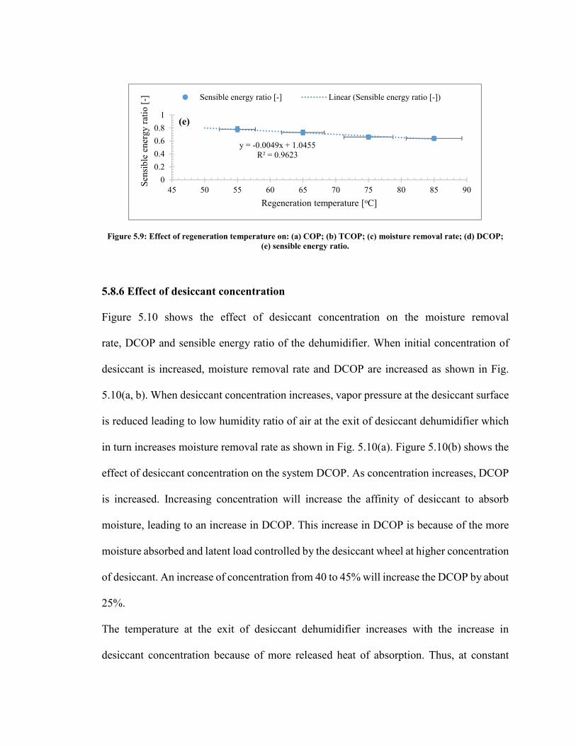
143
Figure 5.9: Effect of regeneration temperature on: (a) COP; (b) TCOP; (c) moisture removal rate; (d) DCOP; (e) sensible energy ratio.
5.8.6 Effect of desiccant concentration
Figure 5.10 shows the effect of desiccant concentration on the moisture removal
rate, DCOP and sensible energy ratio of the dehumidifier. When initial concentration of
desiccant is increased, moisture removal rate and DCOP are increased as shown in Fig.
5.10(a, b). When desiccant concentration increases, vapor pressure at the desiccant surface
is reduced leading to low humidity ratio of air at the exit of desiccant dehumidifier which
in turn increases moisture removal rate as shown in Fig. 5.10(a). Figure 5.10(b) shows the
effect of desiccant concentration on the system DCOP. As concentration increases, DCOP
is increased. Increasing concentration will increase the affinity of desiccant to absorb
moisture, leading to an increase in DCOP. This increase in DCOP is because of the more
moisture absorbed and latent load controlled by the desiccant wheel at higher concentration
of desiccant. An increase of concentration from 40 to 45% will increase the DCOP by about
25%.
The temperature at the exit of desiccant dehumidifier increases with the increase in
desiccant concentration because of more released heat of absorption. Thus, at constant
y = -0.0049x + 1.0455R² = 0.9623
0
0.2
0.4
0.6
0.8
1
45 50 55 60 65 70 75 80 85 90
Sen
sibl
e en
ergy
rat
io [
-]
Regeneration temperature [oC]
(e)
Sensible energy ratio [-] Linear (Sensible energy ratio [-])

144
value of regeneration temperature, sensible energy ratio increase with the increase in
desiccant concentration as shown in Fig. 5.10(c).
Figure 5.10: Effect of desiccant concentration on: (a) moisture removal rate; (b) DCOP; (c) sensible energy ratio.
y = 0.0002x - 0.0078R² = 0.9067
00.0005
0.0010.0015
0.0020.0025
0.003
39 40 41 42 43 44 45
Moi
stur
e re
mov
al r
ate
[kg/
s]
Desiccant concentration [%]
(a)
Moisture removal rate [kg/s] Linear (Moisture removal rate [kg/s])
y = 0.07x - 2.2167R² = 0.8547
0
0.2
0.4
0.6
0.8
1
39 40 41 42 43 44 45
DC
OP
[-]
Desiccant concentration [%]
(b)
DCOP [-] Linear (DCOP [-])
y = 0.01x + 0.2067R² = 0.9231
0.58
0.6
0.62
0.64
0.66
0.68
39 40 41 42 43 44 45Sen
sibl
e en
ergy
rat
io [
-]
Desiccant concentration [%]
(c)
Sensible energy ratio [-] Linear (Sensible energy ratio [-])
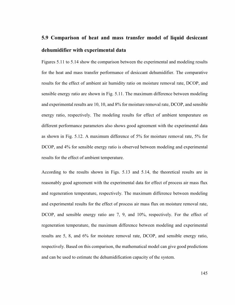
145
5.9 Comparison of heat and mass transfer model of liquid desiccant
dehumidifier with experimental data
Figures 5.11 to 5.14 show the comparison between the experimental and modeling results
for the heat and mass transfer performance of desiccant dehumidifier. The comparative
results for the effect of ambient air humidity ratio on moisture removal rate, DCOP, and
sensible energy ratio are shown in Fig. 5.11. The maximum difference between modeling
and experimental results are 10, 10, and 8% for moisture removal rate, DCOP, and sensible
energy ratio, respectively. The modeling results for effect of ambient temperature on
different performance parameters also shows good agreement with the experimental data
as shown in Fig. 5.12. A maximum difference of 5% for moisture removal rate, 5% for
DCOP, and 4% for sensible energy ratio is observed between modeling and experimental
results for the effect of ambient temperature.
According to the results shown in Figs. 5.13 and 5.14, the theoretical results are in
reasonably good agreement with the experimental data for effect of process air mass flux
and regeneration temperature, respectively. The maximum difference between modeling
and experimental results for the effect of process air mass flux on moisture removal rate,
DCOP, and sensible energy ratio are 7, 9, and 10%, respectively. For the effect of
regeneration temperature, the maximum difference between modeling and experimental
results are 5, 8, and 6% for moisture removal rate, DCOP, and sensible energy ratio,
respectively. Based on this comparison, the mathematical model can give good predictions
and can be used to estimate the dehumidification capacity of the system.

146
0
0.0002
0.0004
0.0006
0.0008
0.001
0.0012
0.0014
0.0016
0.010 0.013 0.016 0.019 0.022 0.025 0.028
Moi
stur
e re
mov
al r
ate
[kg/
s]
Ambient air humidity ratio [kg/kg]
(a)
Theoretical Experimental
0
0.2
0.4
0.6
0.8
1
1.2
0.01 0.013 0.016 0.019 0.022 0.025 0.028
DC
OP
[-]
Inlet air humidity ratio [kg/kg]
(b)
Theoretical Experimental
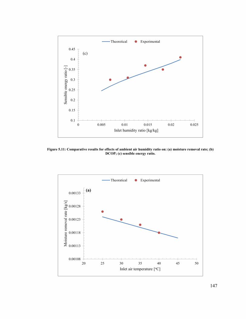
147
Figure 5.11: Comparative results for effects of ambient air humidity ratio on: (a) moisture removal rate; (b) DCOP; (c) sensible energy ratio.
0.1
0.15
0.2
0.25
0.3
0.35
0.4
0.45
0 0.005 0.01 0.015 0.02 0.025
Sen
sibl
e en
ergy
rat
io [
-]
Inlet humidity ratio [kg/kg]
(c)
Theoretical Experimental
0.00108
0.00113
0.00118
0.00123
0.00128
0.00133
20 25 30 35 40 45 50
Moi
stur
e re
mov
al r
ate
[kg/
s]
Inlet air temperature [oC]
(a)
Theoratical Experimental

148
Figure 5.12: Comparative results for effects of ambient air temperature on: (a) moisture removal rate; (b) DCOP; (c) sensible energy ratio.
0.2
0.25
0.3
0.35
0.4
0.45
0.5
0.55
0.6
0.65
20 25 30 35 40 45 50
DC
OP
[-]
Inlet air temperature [oC]
(b)
Theoratical Experimental
0.58
0.6
0.62
0.64
0.66
0.68
0.7
0.72
20 25 30 35 40 45 50
Sen
sibl
e en
ergy
rat
io [
-]
Inlet air temperature [oC]
(c)
Theoratical Experimental
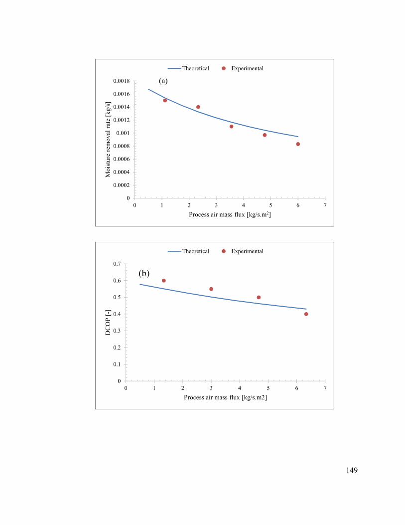
149
0
0.0002
0.0004
0.0006
0.0008
0.001
0.0012
0.0014
0.0016
0.0018
0 1 2 3 4 5 6 7
Moi
stur
e re
mov
al r
ate
[kg/
s]
Process air mass flux [kg/s.m2]
(a)
Theoretical Experimental
0
0.1
0.2
0.3
0.4
0.5
0.6
0.7
0 1 2 3 4 5 6 7
DC
OP
[-]
Process air mass flux [kg/s.m2]
(b)
Theoretical Experimental

150
Figure 5.13: Comparative results for effects of process air mass flux on: (a) moisture removal rate; (b) DCOP; (c) sensible energy ratio.
0
0.05
0.1
0.15
0.2
0.25
0.3
0.35
0.4
0.45
0.5
0 1 2 3 4 5 6 7
Sen
sibl
e en
ergy
rat
io [
-]
Process air mass flux [kg/s.m2]
(c)
Theoretical Experimental
0
0.0002
0.0004
0.0006
0.0008
0.001
0.0012
0.0014
0.0016
45 50 55 60 65 70 75 80 85 90
Moi
stur
e re
mov
al r
ate
[kg/
s]
Regeneration temperature [oC]
(a)
Theoretical Experimental

151
Figure 5.14: Comparative results for effects of regeneration temperature on: (a) moisture removal rate; (b) DCOP; (c) sensible energy ratio.
0.3
0.35
0.4
0.45
0.5
0.55
0.6
0.65
45 50 55 60 65 70 75 80 85 90
DC
OP
[-]
Regeneration temperature [oC]
(b)
Theoretical Experimental
0.3
0.4
0.5
0.6
0.7
0.8
0.9
45 50 55 60 65 70 75 80 85 90
Sen
sibl
e en
ergy
rat
io [
-]
Regeneration temperature [oC]
(c)
Theoretical Experimental

152
5.10 Conclusions
The performance of rotary liquid desiccant cooling system was investigated experimentally
and is presented in this chapter. The effects of different performance parameters such as
ambient air humidity ratio and temperature, process and regeneration air mass flux,
regeneration temperature, and desiccant concentration have been investigated. The
obtained results show that sensible energy ratio and dehumidification performance (DCOP)
of the system increases with increase in ambient air humidity ratio. This is because of the
increase in driving force for mass transfer between air and desiccant surface.
When the regeneration temperature increases, the DCOP decreased due to increase in input
energy at higher regeneration temperature. The SER was lower at higher regeneration
temperatures because of the significant differences between the regeneration and the
process inlet temperatures. A higher regeneration temperature would bring a reduced
marginal benefit, with respect to the latent performance. The COP, ECOP, and TCOP are
largely affected by ambient air conditions, mass flow rates, regeneration temperature, and
desiccant concentration. The other major findings can be summarized as:
• It has been found that the effective control of dehumidification capacity can be
achieved by regulating the temperature and humidity of the air entering the
dehumidifier.
• The higher the ambient air humidity, the higher the cooling capacity of the system
and the lower the thermal energy demand for the system. Therefore, the COP,
ECOP and TCOP increase with ambient air humidity ratio.
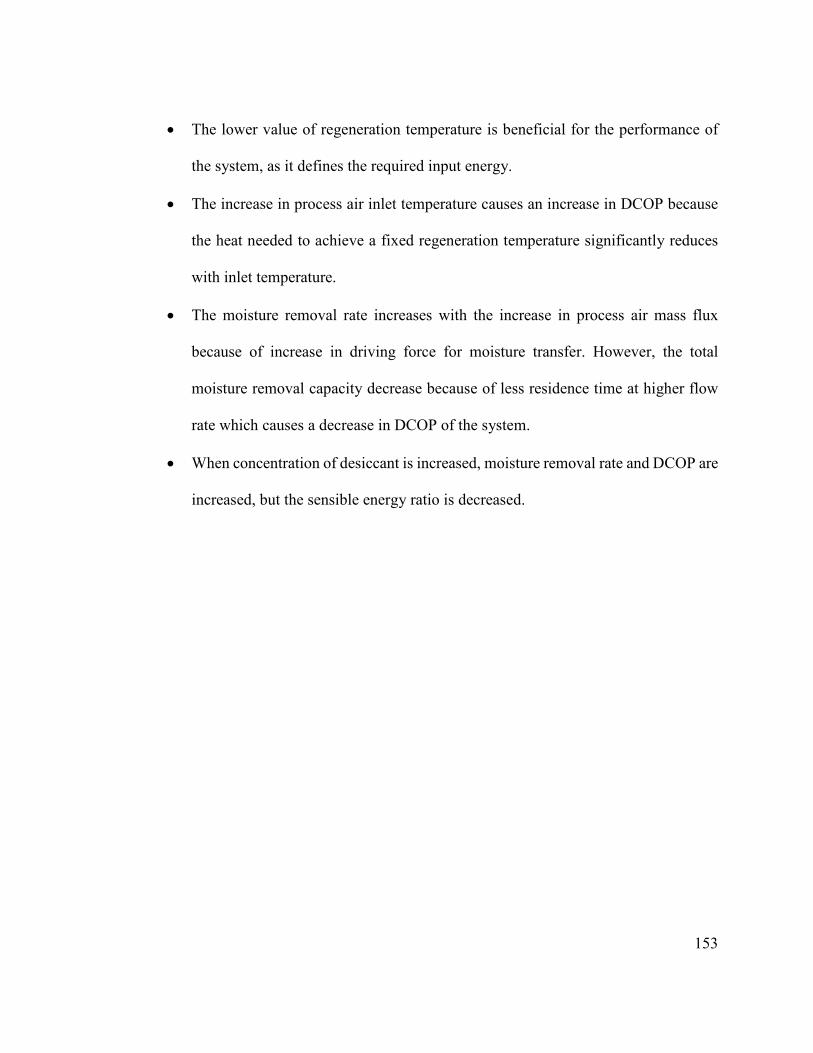
153
• The lower value of regeneration temperature is beneficial for the performance of
the system, as it defines the required input energy.
• The increase in process air inlet temperature causes an increase in DCOP because
the heat needed to achieve a fixed regeneration temperature significantly reduces
with inlet temperature.
• The moisture removal rate increases with the increase in process air mass flux
because of increase in driving force for moisture transfer. However, the total
moisture removal capacity decrease because of less residence time at higher flow
rate which causes a decrease in DCOP of the system.
• When concentration of desiccant is increased, moisture removal rate and DCOP are
increased, but the sensible energy ratio is decreased.

154
6 CHAPTER 6
FEASIBILITY ANALYSIS OF SOLID DESICCANT
COOLING SYSTEM UNDER CLIMATIC ZONE
OF DHAHRAN, SAUDI ARABIA
The control of air conditioning latent and sensible load separately by using a desiccant
dehumidifier operating in conjunction with evaporative cooler can reduce the air
conditioning power requirement effectively. This system can also utilize the alternative
resources of energy that is, solar, waste heat, and natural gas. In this chapter a solar powered
solid desiccant cooling system composed of silica gel desiccant wheel is studied
theoretically and performance of the system is analyzed for its feasibility analysis under
the climatic conditions of Dhahran, Saudi Arabia for three months (April, July, and
October) based on constant effectiveness of heat exchanger and evaporative cooler. The
performance of the system is also studied under different values of process air flow rates
(1 - 3 kg/s), ratio of regeneration to process air flow rates (0.33 - 1), and regeneration
temperatures (120 -200oC). Performance curves have been drawn to get optimum values
of parameters under different operating conditions. The results showed that the proposed
system is feasible for the climatic conditions of Dhahran, Saudi Arabia. It has also been
observed that ratio of regeneration to process air flow rate affects the system performance
remarkably, because it directly affects the regeneration load and COP of the system. The
maximum value of required regeneration load was 118, 59, 38 kW at mass flow rate ratios

155
of 1, 0.5, 0.33, respectively. In order to lower the manufacturing cost of the system only
one evaporative cooler was utilized to cool both process and regeneration air.
6.1 Introduction
Two types of loads (latent and sensible) need to be controlled in any air conditioning
system to achieve comfort temperatures of 20-26oC and relative humidity of 30-60% for
human comfort. The conventional air conditioning systems can control the sensible load
effectively but in order to control the latent load, some alternative cooling methods are
required. Desiccant cooling system (DCS) is a suitable and cost effective alternate,
especially in climates with high latent loads [237, 238]. The desiccant cooling technology
can be utilized as standalone or it can be combined with conventional air conditioning
system.
In a conventional system large amount of energy is consumed to cool down the air below
its dew point temperature to remove the moisture from the air and then to reheat the air up
to the desired supply temperature. While in a hybrid desiccant cooling system, adsorbent
with high affinity for water vapor (silica gel, titanium dioxide, etc.) is used to extract the
water from the air and excessive energy consumed to cool and reheat the air can be saved
which greatly enhances the overall energy efficiency of the system [239].
Desiccant cooling system limits the use of primary energy by utilizing alternative resources
of low grade thermal energy such as, solar energy, waste heat, etc. Some other advantages
of desiccant cooling technology are [240]; (i) low consumption of electrical energy; (ii)
eliminates the use of Chlorofluorocarbons which causes depletion of ozone layer; (iii)

156
better control of humidity because latent and sensible loads are controlled separately; (iv)
better indoor air quality by controlling the growth of harmful fungi and bacteria. Arundel
et al. [241] graphically represented a suitable range of relative humidity for the growth of
different fungi and bacteria as shown in Fig. 6.1.
Figure 6.1: Microbial growth as a function of relative humidity [241].
6.2 Description of solid desiccant cooling cycles
Commonly used solid desiccant cooling cycles are:
• Ventilation cycle
• Recirculation cycle
• Dunkle cycle
• Recirculation ventilated cycle
• Wet-surface heat exchanger (WSHE)
• Three mixed-mode cycles
The recirculation cycle utilizes 100% recirculation of air, which means the returned air
from the room is mixed with the process air at the inlet of desiccant wheel. Dunkle

157
recirculation cycle [60] has an additional heat exchanger with 100% recirculation of air
through the dehumidifier while for regeneration of desiccant wheel, outdoor air is used.
The recirculation and Dunkle cycles are 100% recirculation which is practically not much
effective and desirable. However, in both cycles return air can be mixed with ventilation
air according to the requirement. Both recirculation and Dunkle cycles were also analyzed
with 10% ventilation air mixed with the return air, this cycle is called as recirculation
ventilated and Dunkle ventilated cycle.
Maclaine-Cross and Banks [62] developed an idea of wet-surface heat exchanger (WSHE),
in which water indirectly cools the process air. The extraction which is the ratio of
circulated air and return air is kept about 50%. The wet surface heat exchanger cycle is
actually an ideal cycle with two wet surface heat exchangers. In advanced WSHE cycle
along with two wet surface heat exchangers, two sensible heat exchangers are used. Three
mixed-mode cycles reported by Maclaine-Cross [242] and Kant and Maclaine-Cross [64]
in which evaporative coolers are replaced by regenerative/wet surface heat exchangers.
The purpose of regenerative/wet surface heat exchanger is to decrease the dry bulb
temperature without much increase in humidity of the air. According to Jain et al. [94], the
cycle utilizing WSHE can operate with higher coefficient of performance compared to
other cycles. The advanced WSHE cycle has maximum COP of 2.6. Dunkle cycle has
better performance than ventilation and recirculation cycles.
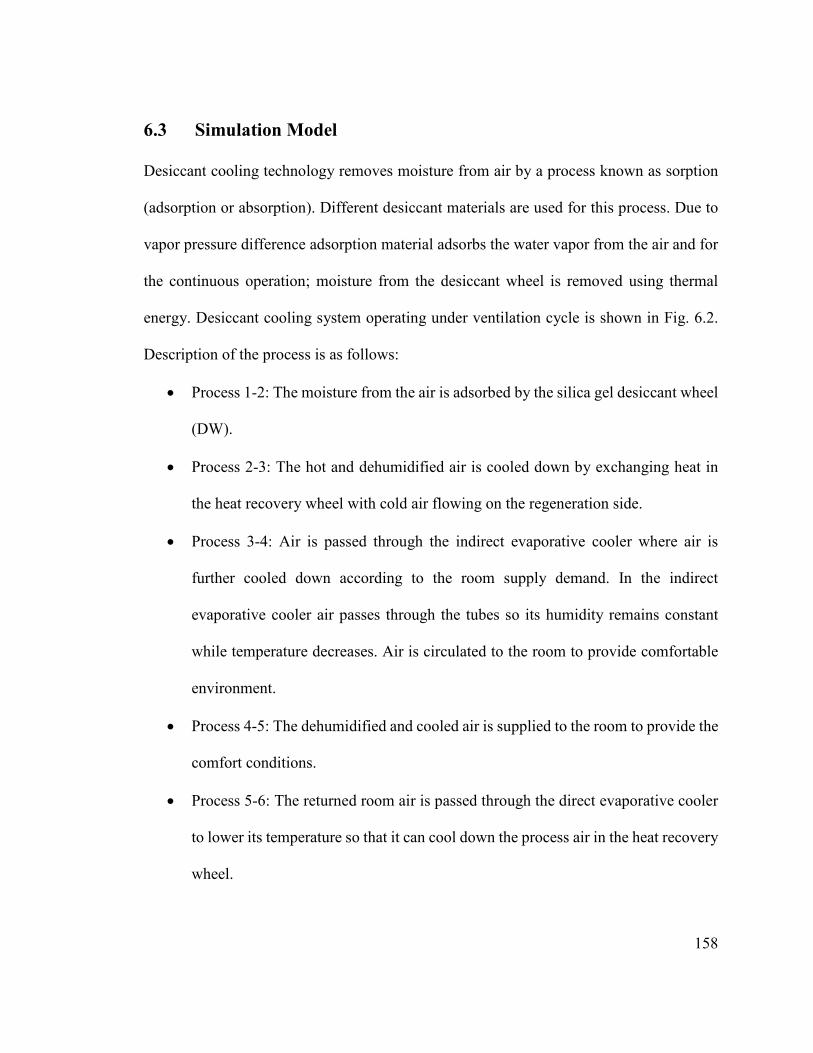
158
6.3 Simulation Model
Desiccant cooling technology removes moisture from air by a process known as sorption
(adsorption or absorption). Different desiccant materials are used for this process. Due to
vapor pressure difference adsorption material adsorbs the water vapor from the air and for
the continuous operation; moisture from the desiccant wheel is removed using thermal
energy. Desiccant cooling system operating under ventilation cycle is shown in Fig. 6.2.
Description of the process is as follows:
• Process 1-2: The moisture from the air is adsorbed by the silica gel desiccant wheel
(DW).
• Process 2-3: The hot and dehumidified air is cooled down by exchanging heat in
the heat recovery wheel with cold air flowing on the regeneration side.
• Process 3-4: Air is passed through the indirect evaporative cooler where air is
further cooled down according to the room supply demand. In the indirect
evaporative cooler air passes through the tubes so its humidity remains constant
while temperature decreases. Air is circulated to the room to provide comfortable
environment.
• Process 4-5: The dehumidified and cooled air is supplied to the room to provide the
comfort conditions.
• Process 5-6: The returned room air is passed through the direct evaporative cooler
to lower its temperature so that it can cool down the process air in the heat recovery
wheel.

159
• Process 6-7: Heat is exchanged between cooled regeneration air and hot process air
in heat recovery wheel (HRW). Note that, the mass flow rate of regeneration air
entering at state 5 is equal to the mass flow rate of process air at state 1 for better
exchange of heat between process and regeneration air.
• Process 7-8: At state 7 about 50-75% of process air is bypassed the heater so that
heating load can be decreased. The rest of the air is heated up to regeneration
temperature by solar collector.
• Process 8-9: Desiccant is regenerated using hot air. During process of regeneration
the adsorbed moisture is desorbed to repeat the cycle again.
1 2 3 4
56789
Supply air
Exhaust air
Desiccant wheel Heat recovery wheelHeater Direct evaporative cooler
Indirect evaporative cooler
Process air stream
Regeneration air stream
(a)
Dry bulb temperature (oC)
Hum
idity
ratio
(kg
/kg)
(b)
1
234
7
5
68
9
By pass
Figure 6.2: (a) Systematic solid desiccant cooling system with indirect evaporative cooler (b) psychrometric processes.

160
6.4 Cycle analysis
The following assumptions are made in order to perform the theoretical analysis of
desiccant cooling system:
(1) Silica gel desiccant wheel has regeneration temperature of about 120-200oC.
(2) Indirect evaporative cooler has effectiveness of about 85-90%
(3) The heat recovery wheel has effectiveness of about 80%.
(4) The flow rate of process and return air are equal but about 50 to 75% regeneration
air is bypassed at state 7 to reduce regeneration heat required as shown in Fig. 6.2.
Temperature and moisture conditions at the exit from the silica gel desiccant wheel can be
found from silica gel performance curves [243]. The effectiveness of the heat recovery
wheel can be expresses as
���� = W� X ×(b�Jb�)W� \×(b�Jb�) (6.1)
The effectiveness of both evaporative coolers is given by
����,> = (b�Jb )(b�Jb¡�) (6.2)
�¢��,� = (b{Jb�)(b{Jb¡{) (6.3)
Here £ and £� represents the dry and wet bulb temperatures, respectively. Also, from the
energy and mass balances it can be written
£¤ = £¥ + (b�Jb�)W� \/W� X (6.4)
£§ = £̈ + (b�Jb�)W� \/W� X (6.5)
A§ = A¨ + (G�JG�)W� \/W� X (6.6)

161
6.5 Performance Index
The system coefficient of performance (COP) is given as the ratio of the system cooling
load and regeneration heat required
TUV = ©��©�\ (6.7)
The cooling load and regeneration heat is given as
�� = �� > × (ℎ� − ℎ�) (6.8)
�� = �� � × (ℎ¨ − ℎ¤) (6.9)
The total capacity of moisture removal for the system is represented as the moisture
absorbed from the air by the desiccant wheel.
=> = �� > × (A� − A�) (6.10)
The desiccant wheel effectiveness on the dehumidification (process) side is given by;
�Bw = (G�JG�)(G�JG�,ILMHN) (6.11)
Where, A�,DPQBR represents the ideal specific humidity ratio. Assuming that at this point if
air is completely dehumidified, we can take A�,DPQBR=0. Similarly, on the regeneration side
��Qª = (GzJG«)Gz (6.12)
6.6 Results and discussion
The purpose of this theoretical investigation is to analyze the performance of a solid
desiccant cooling system operating on the ventilation cycle as shown in Fig. 6.2.
Theoretical results are obtained under the climatic conditions of Dhahran, Saudi Arabia for
three different months. The hourly solar radiation, inlet air dry bulb temperature and

162
humidity ratio are listed in Tables 6.1, 6.2, and 6.3. The unknown conditions of the air at
each point of the cycle are determined using equation (6.1 - 6.12) and the psychrometric
chart. The built in function of Engineering Equation Solver (EES) is used to obtain the
thermodynamic properties of moist and dry air. The range and base values of operating
parameters have been shown in Table 6.4.
Table 6.1: Meteorological Data of Dhahran, Saudi Arabia for the month of April (15th April).
Time (hours)
Solar Radiation (W/m2)
Dry bulb temperature (oC)
Relative humidity (%)
06:00 33.41 19.44 75.78 07:00 228.7 20.9 56.84 08:00 463.1 21.74 57.35 09:00 685.7 24.03 38.02 10:00 847 26.72 22.94 11:00 943 27.6 17.84 12:00 987 28.05 15.9 13:00 959 28.18 15.11 14:00 814 28.46 16.11 15:00 673.6 28.53 17.87 16:00 447.8 27.38 27.39 17:00 168.9 26.23 35.12 18:00 43.81 24.82 45.98 19:00 0 23.84 51.33 20:00 0 23.85 46.49

163
Table 6.2: Meteorological Data of Dhahran, Saudi Arabia for the month of July (17th July).
Time (hours)
Solar Radiation (W/m2)
Dry bulb temperature (oC)
Relative humidity (%)
06:00 56.07 31.67 69.07 07:00 235.1 32.11 66.25 08:00 448.9 33.74 51.68 09:00 639.3 36.86 29.43 10:00 787.8 38.74 20.13 11:00 862 40.2 17.61 12:00 875 41.48 18.66 13:00 860 41.02 21.02 14:00 797.8 39.22 31.81 15:00 676.1 37.69 44.79 16:00 493.4 35.57 62.88 17:00 292.5 34.54 66.46 18:00 109.2 34.19 65.39 19:00 8.38 33.25 72.52 20:00 0 32.9 74.59
Table 6.3: Meteorological Data of Dhahran, Saudi Arabia for the month of October (15th October).
Time (hours)
Solar Radiation (W/m2)
Dry bulb temperature (oC)
Relative humidity (%)
06:00 7.13 25.34 25.82 07:00 145.8 25.45 26.73 08:00 394.7 26.67 29.36 09:00 427.5 28.37 31.8 10:00 676.6 30.74 32.98 11:00 797.8 32.39 27.66 12:00 827 33.26 28.5 13:00 780.6 33.63 26.04 14:00 644.7 33.78 25.62 15:00 475.4 33.91 18.88 16:00 289.4 33.61 16.81 17:00 85.3 32.72 21.59 18:00 1.274 31.61 29.23 19:00 0 30.81 35.33 20:00 0 30.19 41.78

164
Table 6.4: Operating parameters.
Parameter Value range Base value
Process air flow rate (kg/s) 0.5 – 3.5 1.62
Regeneration air flow rate (kg/s) 0.5 – 3.5 0.54
Regeneration air temperature (oC) 120 – 200 140
Desiccant material Silica gel -
Figure 6.3 shows the amount of hourly moisture removed from the process air during the
day for the three months. The removed moisture depends on different parameters such as
inlet air humidity ratio, air flow rate and the desiccant wheel material which is silica gel in
this study. The removed moisture is following the same trend as the humidity of inlet air.
The maximum amount of moisture removed from the process air is 0.008, 0.017 and 0.006
kg/kg for the month of April, July and October, respectively.
Figures 6.4 and 6.5 represent the variations of wheel effectiveness on process and
regeneration side, respectively, during the day. It is observed that the value of effectiveness
on process side was greater as compared to the regeneration side for all three months. The
maximum values of wheel effectiveness on process side achieved were 0.78, 0.65 and 0.7
for the month of April, July, and October, respectively at a flow rate of 1.62 kg/s
(3000CFM). While at the same operating conditions for the regeneration side the achieved
effectiveness values were 0.56, 0.48 and 0.53, respectively. The wheel effectiveness is high
for months with high humidity ratio of ambient air.
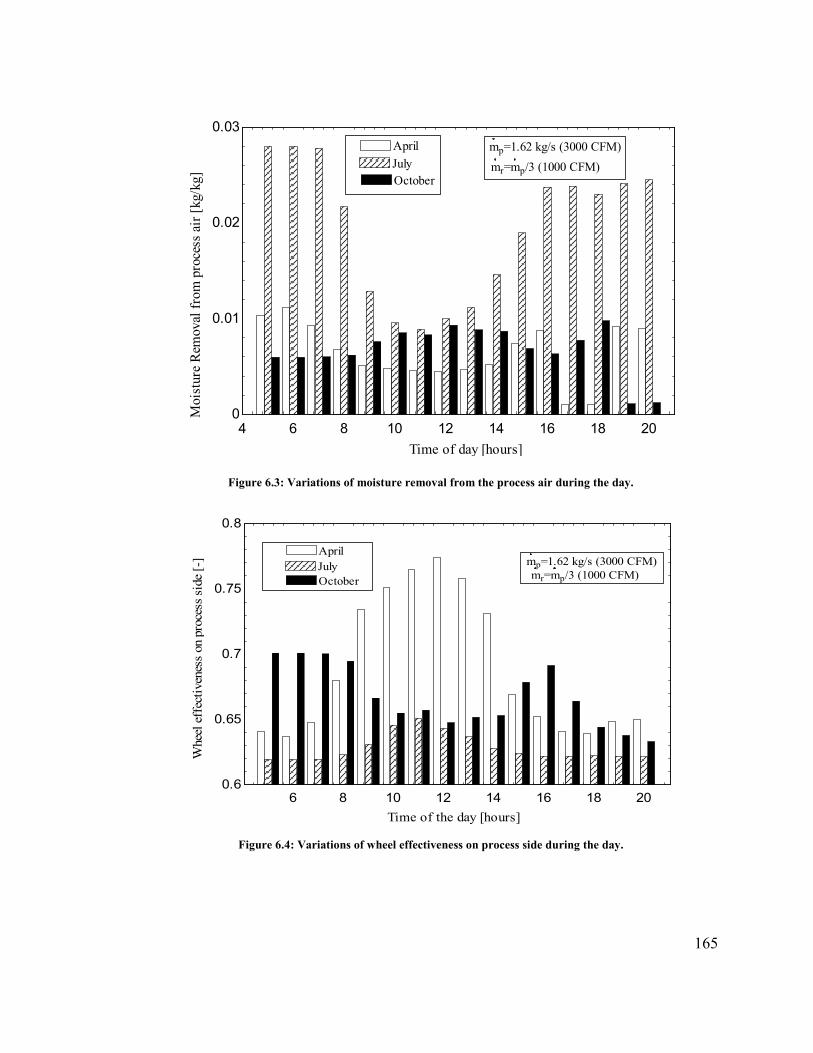
165
Figure 6.3: Variations of moisture removal from the process air during the day.
Figure 6.4: Variations of wheel effectiveness on process side during the day.
4 6 8 10 12 14 16 18 20
0
0.01
0.02
0.03
Time of day [hours]
Moi
stur
e R
emov
al f
rom
pro
cess
air
[kg
/kg]
April
JulyJulyOctoberOctober
mp=1.62 kg/s (3000 CFM)
mr=mp/3 (1000 CFM)
6 8 10 12 14 16 18 20
0.6
0.65
0.7
0.75
0.8
Time of the day [hours]
Whe
el e
ffec
tive
ness
on
proc
ess
side
[-] mp=1.62 kg/s (3000 CFM)
mr=mp/3 (1000 CFM)
AprilAprilJulyJulyOctoberOctober
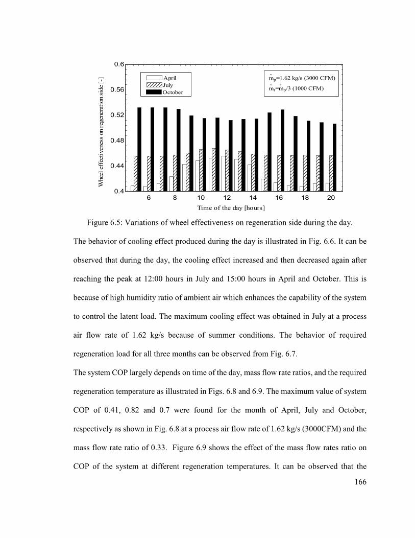
166
Figure 6.5: Variations of wheel effectiveness on regeneration side during the day.
The behavior of cooling effect produced during the day is illustrated in Fig. 6.6. It can be
observed that during the day, the cooling effect increased and then decreased again after
reaching the peak at 12:00 hours in July and 15:00 hours in April and October. This is
because of high humidity ratio of ambient air which enhances the capability of the system
to control the latent load. The maximum cooling effect was obtained in July at a process
air flow rate of 1.62 kg/s because of summer conditions. The behavior of required
regeneration load for all three months can be observed from Fig. 6.7.
The system COP largely depends on time of the day, mass flow rate ratios, and the required
regeneration temperature as illustrated in Figs. 6.8 and 6.9. The maximum value of system
COP of 0.41, 0.82 and 0.7 were found for the month of April, July and October,
respectively as shown in Fig. 6.8 at a process air flow rate of 1.62 kg/s (3000CFM) and the
mass flow rate ratio of 0.33. Figure 6.9 shows the effect of the mass flow rates ratio on
COP of the system at different regeneration temperatures. It can be observed that the
6 8 10 12 14 16 18 20
0.4
0.44
0.48
0.52
0.56
0.6
Time of the day [hours]
Whe
el e
ffec
tive
ness
on
rege
nera
tion
sid
e [-
] mp=1.62 kg/s (3000 CFM)
mr=mp/3 (1000 CFM)
AprilAprilJulyJulyOctoberOctober

167
system COP decreases with the increase in mass flow rates ratio and required regeneration
temperature. This decrease in COP is due to increase in regeneration load with the increase
in mass flow rates ratio and required regeneration temperature. Figure 6.10 shows the
strong dependence of required regeneration heat on the value of mass flow rate ratio during
the day. As, the value of regeneration air flow rate decreases or the ratio decreases, the
required regeneration load decreases which in turns increases the system overall
performance.
The maximum value of required regeneration load was 118, 59, 38 kW at ratio of mass
flow rates of 1, 0.5, 0.33, respectively as it can be observed from Fig. 6.10. The value of
this ratio of mass flow rate is controlled by bypassing the air at point 7 as shown in Fig.
6.2. The obtained results for performance of the system at different regeneration
temperatures followed the same trend as experimental investigation for the desiccant
cooling system carried out by Panaras et al. [244].
Figure 6.11 shows the variations of cooling effect produced for different values of process
air mass flow rate. The cooling effect produced strongly depends on the value of process
air flow rate. The cooling effect increased from 22 to 78 kW as the mass flow rate increased
from 1 to 3 kg/s. It is observed that maximum value of cooling effect produced was 39 kW
at a process air flow rate of 1.62 kg/s (3000 CFM) while this value increased to 52 kW as
process air flow rate increased to 2.15 kg/s (4000 CFM). Similarly, the moisture removal
capacity of the desiccant wheel increased with the increase in process air flow rate as
illustrated in Fig. 6.12.
.
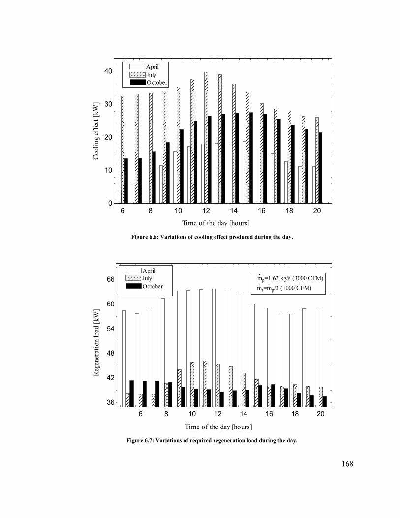
168
Figure 6.6: Variations of cooling effect produced during the day.
Figure 6.7: Variations of required regeneration load during the day.
6 8 10 12 14 16 18 20
0
10
20
30
40AprilJulyOctober
Time of the day [hours]
Coo
ling
eff
ect [
kW]
6 8 10 12 14 16 18 20
36
42
48
54
60
66
Reg
ener
atio
n lo
ad [
kW]
Time of the day [hours]
mp=1.62 kg/s (3000 CFM)AprilJulyOctober mr=mp/3 (1000 CFM)

169
Figure 6.8: Variations of COP during the day.
Figure 6.9: Variations of COP for different ratios of mass flow rates.
6 8 10 12 14 16 18 20
0
0.2
0.4
0.6
0.8
1
1.2
Coe
ffic
ient
of
perf
orm
ance
[-]
Time of the day [hours]
mp=1.62 kg/s (3000 CFM)
mr=mp/3 (1000 CFM)
April
JulyOctober
0.2 0.3 0.4 0.5 0.6 0.7 0.8 0.9 1
0.2
0.4
0.6
0.8
1
1.2
1.4
mr/mp
Coe
ffic
ient
of
perf
orm
ance
[-]
mp=1.62 kg/s (3000 CFM)
Tregeneration [oC]
120120140140160160
180180
200200
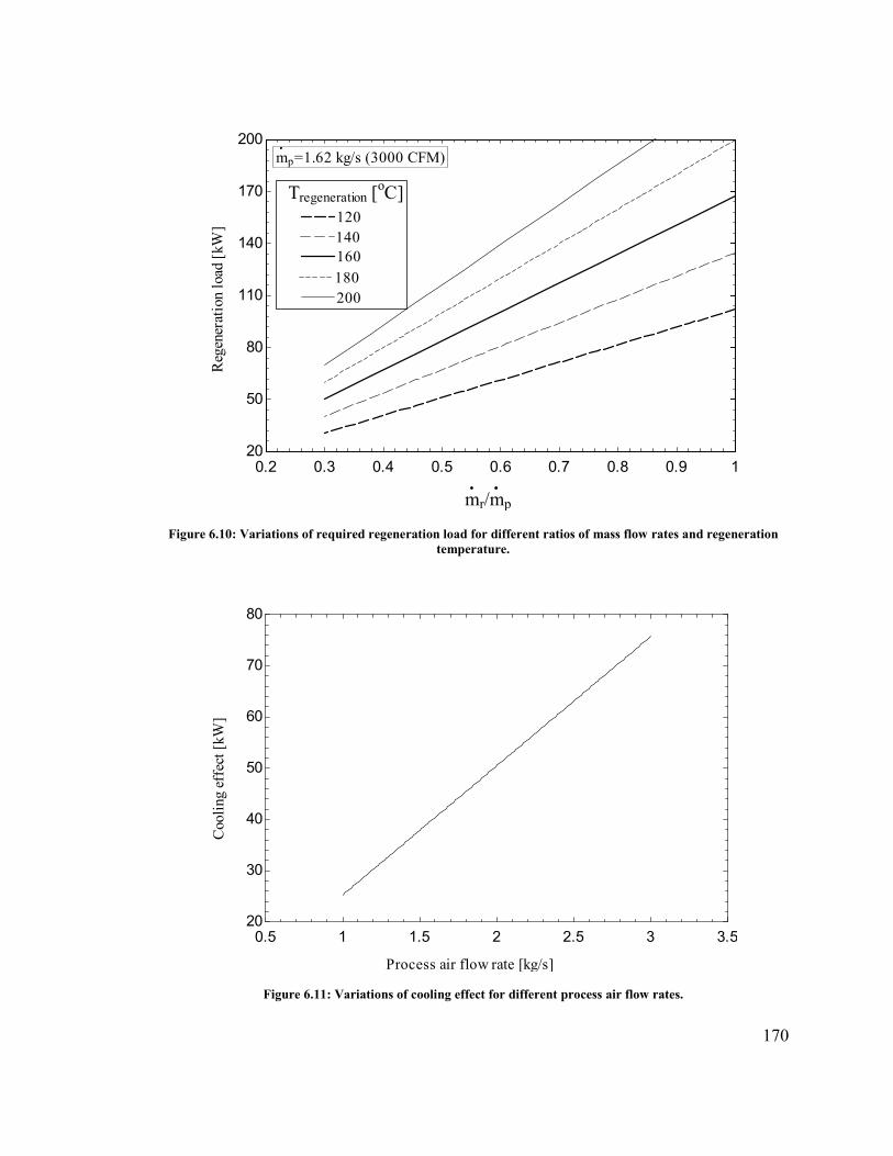
170
Figure 6.10: Variations of required regeneration load for different ratios of mass flow rates and regeneration temperature.
Figure 6.11: Variations of cooling effect for different process air flow rates.
0.2 0.3 0.4 0.5 0.6 0.7 0.8 0.9 1
20
50
80
110
140
170
200
mr/mp
Reg
ener
atio
n lo
ad [
kW]
mp=1.62 kg/s (3000 CFM)
Tregeneration [oC]
120120140140160160180180200200
0.5 1 1.5 2 2.5 3 3.5
20
30
40
50
60
70
80
Process air flow rate [kg/s]
Coo
ling
eff
ect [
kW]

171
Figure 6.12: Variations of moisture removal capacity for various process air mass flow rates.
6.7 Conclusions
In this chapter a mathematical model for solid desiccant cooling system using a rotary
wheel composed of silica gel have been developed to carry out the feasibility analysis of
the system operating in conjunction with evaporative cooler under climatic conditions of
Dhahran, Saudi Arabia. The system performance was studied for different operating
parameters like process and regeneration air flow rate, humidity of process air, and
regeneration temperature. The following results can be concluded:
• The effectiveness of the desiccant wheel on process and regeneration side depends
on flow rate of air. It approaches 0.65 for the absorption process and 0.48 for the
0.5 1 1.5 2 2.5 3 3.5
0.001
0.0015
0.002
0.0025
0.003
0.0035
0.004
Process air flow rate [kg/s]
Moi
stur
e re
mov
al r
ate
[kg/
s]
172
regeneration process at a flow rate of process air of 1.62 kg/s and flow rate of
regeneration air of 0.54 kg/s for the month of July.
• The maximum amount of moisture removed from the process air was 0.017 kg/kg
at flow rate of process air 1.62 kg/s in July.
• The maximum value of cooling effect produced is 39 kW at a process air flow rate
of 1.62 kg/s (3000CFM) while this value increased to 52 kW as process air flow
rate increased to 2.15 kg/s (4000CFM).
• The maximum value of required regeneration load was 118, 59, 38 kW at ratio of
mass flow rates of 1, 0.5, 0.33, respectively.

173
3 CHAPTER 7
CONCLUSIONS AND FUTURE WORK
7.1 Conclusions
In this thesis, a liquid desiccant cooling system has been theoretically and experimentally
investigated. The system is installed at King Fahd University of Petroleum and Minerals
(KFUPM). Desiccant cooling systems are a great HVAC alternative to high energy
consuming conventional air conditioning units. One of the reasons is that desiccant systems
can be powered by low grade thermal energy sources. The goal of this thesis is to evaluate
the overall system performance with the main focus on dehumidification capability.
A theoretical model for the liquid desiccant dehumidifier was developed to observe the
heat and mass transfer phenomenon for absorption and regeneration process under different
operating parameters such as process air flow rate, temperature and humidity ratio of inlet
air, and thickness of the dehumidifier. Effect of these parameters have also been studied on
dehumidifier effectiveness, moisture removal rate and DCOP.
The necessary temperature of the regeneration air with respect to achieving desired
moisture removal was evaluated in the range of 55 - 90˚C. It was shown that the desiccant
wheel performance was very dependent on the regeneration temperature, air flow rates, and
humidity ratio of the entering process air.

174
Results from the experiments regarding the overall performance indicated that the
desiccant cooling system functioned well under different humidity conditions if the
operating conditions were selected properly. However, the system excelled the most
optimal performance during high absolute humidity conditions.
The desiccant wheel had a very good performance when acting as the dehumidification
unit. When run alone, the desiccant wheel was capable of providing sufficient moisture
removal in the range of 0.010 - 0.013 kgv/kga, and had a high dehumidification
performance.
Parametric studies were employed to examine the enhancement in heat and mass transfer
between the air and the desiccant for different controlling parameters. The mathematical
model of desiccant wheel has been verified with the results obtained from experimental
rig. The experimental results show a good match with values determined from the
mathematical model.
Furthermore, a mathematical model for solid desiccant cooling system using a rotary wheel
composed of silica gel was developed to carry out the feasibility analysis of the system
operating in conjunction with evaporative cooler under climatic conditions of Dhahran,
Saudi Arabia. The system performance was studied for different operating parameters like
process and regeneration air flow rates, humidity of process air, and regeneration
temperature. The results show that, the cooling effect produced by the system increases
from 39 kW to 52kW when flow rate of process air increases from 1.62 kg/s (3000 CFM)
to 2.15 kg/s (4000 CFM).
175
7.2 Recommendations for future work
Although substantial work has been carried out during this research, there are still quite a
few problems needing to be solved, and the performance of the system can still be improved
to some degree.
Based on the results presented in this thesis a simulation model should be developed where
simulated theoretical values and performance indexes can be compared to real
experimental measurements and calculations. This will not only help in the performance
analysis, but also make it easier to identify optimal operation conditions for further testing.
Economic evaluations should be carried out. This will help in evaluating the tradeoff
between the initial cost of purchasing and installing units like pre cooling heat exchangers
and the benefits achieved regarding the system performance. Also, a life cycle assessment
should be performed to investigate the impact the desiccant system has on the environment.
Further, the possibility of applying processed ventilation air to the conditioned space
should be implemented in the system. This can be done by making it possible to divide the
process air into two separate air streams before entering the evaporative cooler. One air
stream is then directed towards the cooler and the other is directed towards the conditioned
space. An air to water heat exchanger should also be installed at a point before the
processed air enters the conditioned space, so that the produced chilled water can be
utilized to cool the supply air. When supplying ventilation air becomes possible,
measurements of the air entering the building should be carried out.
176
A setup that allows for the desiccant system to be used as a heating cycle during the winter
should be investigated. The evacuated tube solar air collectors have high efficiency and
could be able to provide heated fresh air to the conditioned space during cold periods. The
possibility of using the desiccant wheels to humidify the process air if the ambient air is
too dry should also be investigated.

177
REFERENCES
[1] NSI/ASHRAE55, Thermal Environmental Conditions for Human Occupancy, American Society of Heating: Refrigerating and Air-conditioning Engineers, Atlanta, GA, 1992.
[2] Ameen A. The Challenges of air-conditioning in Tropical and Humid Tropical climates, Proceedings of the International Conference on Mechanical Engineering (ICME2005), Dhaka, Bangladesh, 2005.
[3] Davanagere S, Sherif A, Goswami Y. A feasibility study of a solar desiccant air-conditioning system—Part II: Transient simulation and economics, Int. J. Energy Res. 1999; 23(2):103–116.
[4] Henderson HI, Rengarajan K. Model to predict the latent capacity of air-conditioners and heat pumps at part-load conditions with constant fan operation, ASHRAE Transactions 1996; 102(1): 266-274.
[5] Jain S, Dhar PL, Kaushik SC. Evaluation of liquid dessicant based evaporative cooling cycles for typical hot and humid climates, Heat Recovery Syst. 1994; 14(6):621–632.
[6] Qiu GQ, Riffat SB. Novel design and modelling of an evaporative cooling system for buildings, Int. J. Energy Res. 2006; 30(12):985 – 999.
[7] Enteria N, Yoshino H, Mochida A, Takaki R, Satake A, Yoshie R, Mitamura T, Baba S. Synergization of Clean Energy Utilization, Clean Technology Development and Controlled Clean Environment through Thermally Activated Desiccant Cooling System. 2nd International Conference on Energy Sustainability 2008.
[8] Kahn JR, Franceschi D. Beyond Kyoto: A tax-based system for the global reduction of greenhouse gas emissions. Ecol. Econ. 2006; 58(4):778–787.
[9] York R. Demographic trends and energy consumption in European Union Nations, 1960–2025. Social Science Research 2007; 36(3): 855–872.
[10] Luken R, Grof T. The Montreal Protocol’s multilateral fund and sustainable development. Ecol. Econ. 2006; 56(2):241–255.
[11] Barrios S, Bertinelli L, Strobl E. Climatic change and rural–urban migration: The case of sub-Saharan Africa. J. Urban Econ. 2006; 60(3):357-371.
[12] Forster P, Ramaswamy V, Artaxo P, Berntsen T, Betts R, Fahey DW. “Changes in atmospheric constituents and in radiative forcing. In: Solomon S, Qin D, Manning M, Chen Z, Marquis M, Averyt KB, Tignor M, Miller HL, editors. Climate change 2007: the

178
physical science basis. Contribution of Working Group I to the Fourth Assessment Report of the Intergovernmental Panel on Climate Change. Cambridge, United Kingdom and New York, NY, USA: Cambridge University Press,” 2007.
[13] Strum M, Cook R, Thurman J, Ensley D, Pope A, Palma T, Mason R, Michaels H, Shedd S. Projection of hazardous air pollutant emissions to future years. Sci. Total Environ. 2006; 366(2):590–601.
[14] Barkenbus JN. Putting Energy Efficiency in a Sustainability Context: The Cold Facts about Refrigerators. Environ. Sci. Policy Sustain. Dev. 2006; 48(8):10–20.
[15] Radhwan AM, Gari HN, Elsayed MM. Parametric study of a packed bed dehumidifier/regenerator using CaCl2 liquid desiccant. Renewable Energy 1993; 3(1):49–60.
[16] IEA. “Key world energy statistics. Paris, France: International Energy Agency” 2008.
[17] Coiante D, Barra L. Renewable energy capability to save carbon emissions. Sol. Energy 1996; 57(6): 485–491.
[18] Yu BF, Hu ZB, Liu M, Yang HL, Kong QX, Liu YH. Review of research on air-conditioning systems and indoor air quality control for human health. Int. J. Refrig. 2009; 32(1):2009.
[19] Afonso CFA. Recent advances in building air conditioning systems. Appl. Therm. Eng. 2006; 26(16): 1961–1971.
[20] Farber EA. Solar energy, its conversion and utilization. Sol. Energy 1973; 14(3):243–252.
[21] Henning HM. Solar assisted air conditioning of buildings – an overview. Appl. Therm. Eng. 2007; 27(10):1734–1749.
[22] Enteria N, Mizutani K. Solar Energy Sciences and Engineering Application. CRC Press, (2013).
[23] Renewable energy trends, Energy information administration, USA, 2004.
[24] Kahn JR, and Franceschi D. Beyond Kyoto: A tax-based system for the global reduction of greenhouse gas emissions, Ecol. Econ. 2006; 58(4):778–787.
[25] York R. Demographic trends and energy consumption in European Union Nations, 1960–2025, Soc. Sci. Res. 2007; 36(3):855–872.

179
[26] Barrios S, Bertinelli L, and Strobl E. Climatic change and rural–urban migration: The case of sub-Saharan Africa, J. Urban Econ. 2006; 60(3):357–371.
[27] The Freedonia Group, Inc. “World HVAC equipment demand, Cleveland, Ohio USA", 2012.
[28] Watt JR. Evaporative Air Conditioning Handbook. 3rd edition. Prentice Hall, 1997.
[29] Cerci Y. A new ideal evaporative freezing cycle. Int. J. Heat Mass Transf. 2003; 46(16):2967–2974.
[30] ASHRAE Handbook, Evaporative cooling applications, HVAC Applications, Atlanta: American Society of Heating, Refrigerating and Air-Conditioning Engineers Inc. 2003; 55.1 – 55.3.
[31] Heidarinejad G, Bozorgmehr M, Delfani S, Esmaeelian J. Experimental investigation of two-stage indirect/direct evaporative cooling system in various climatic conditions. Build. Environ. 2009; 44(10):2073–2079.
[32] Joudi KA, Mehdi SM. Application of indirect evaporative cooling to variable domestic cooling load. Energy Convers. Manag. 2000; 41(17):1931–1951.
[33] Saman WY, Alizadeh S. An experimental study of a cross-flow type plate heat exchanger for dehumidification/cooling. Sol. Energy 2002; 73(1):59–71.
[34] Kessling W, Laevemann E, Peltzer M. Energy storage in open cycle liquid desiccant cooling systems. Int. J. Refrig. 1998; 21(2):150–156.
[35] Costelloe B, Finn D. Indirect Evaporative Cooling Potential in Air-water Systems in Temperate Climates. Energy and Buildings 2003; 35:573-591.
[36] Heidarinejad G, Bozorgmehr M, Delfani S, Esmaeelian J. Experimental investigation of two-stage indirect/direct evaporative cooling system in various climatic conditions. Build. Environ. 2009; 44(10):2073–2079.
[37] Shariaty-Niassar M, Gilani N. An Investigation of Indirect Evaporative Coolers, IEC With Respect to Thermal Comfort Criteria. Iran. J. Chem. Eng. 2009; 6(2):14-28.
[38] Kulkarni RK, Rajput SPS. Performance evaluation of two stage indirect/direct evaporative cooler with alternative shapes and cooling media in direct stage. Int. J. Appl. Eng. 2001; 1(4):800.
[39] Bruno F. An indirect evaporative cooler for supplying air near the dew point. 48th AuSES Annual Conference, Canberra, ACT, Australia 2010.
180
[40] Pimenta JMD, Castro WP. Analysis of different applications of evaporative cooling systems. Proc. 17th Int. Congr. Mech. Engineering, Sao Paulo 2003.
[41] Jones WP. Air Conditioning Engineering. 5th Ed. Routledge 2001.
[42] Camargo JR, Ebinuma CD, Silveira JL. Experimental performance of a direct evaporative cooler operating during summer in a Brazilian city. Int. J. Refrig. 2005; 28(7):1124–1132.
[43] Riffat SB, Zhu J. Mathematical model of indirect evaporative cooler using porous ceramic and heat pipe. Appl. Therm. Eng. 2004; 24(4):457–470.
[44] Zhao X, Li JM, Riffat SB. Numerical study of a novel counter-flow heat and mass exchanger for dew point evaporative cooling. Appl. Therm. Eng. 2008; 28(14-15): 1942–1951.
[45] Zhao X, Liu S, Riffat SB. Comparative study of heat and mass exchanging materials for indirect evaporative cooling systems. Build. Environ. 2008; 43(11):1902–1911.
[46] Davis RA. Evaluation of Advanced Evaporative Cooler Technologies; Pacific Gas and Electric (PG&E) Customer Energy Management Emerging Technologies Program; Report No.: 491-04.7, 2004.
[47] Enteria N, Mizutani K. The role of the thermally activated desiccant cooling technologies in the issue of energy and environment. Renew. Sustain. Energy Rev. 2011; 15(4):2095–2122.
[48] Halliday SP, Beggs CB, Sleigh PA. The use of solar desiccant cooling in the UK: a feasibility study. Appl. Therm. Eng. 2002; 22(12):1327–1338.
[49] Enteria N, Yoshino H, Mochida A, Takaki R, Satake A, Yoshie R, Mitamura T, Baba S. Construction and initial operation of the combined solar thermal and electric desiccant cooling system. Sol. Energy 2009; 83(8):1300–1311.
[50] Enteria N, Yoshino H, Satake A, Mochida A, Takaki R, Yoshie R, Baba S. Development and construction of the novel solar thermal desiccant cooling system incorporating hot water production. Appl. Energy 2010; 87(2):478–486.
[51] Henning HM. Solar-Assisted Air-Conditioning in Buildings: A Handbook for Planners, 2nd edition. Wien ; London: Springer Vienna Architecture 2007.
[52] Nayak SM. Experimental and Theoretical Investigation of Integrated Engine Generator - Liquid Desiccant System. Ph.D., Thesis, College Park, University of Maryland, United States 2005.
181
[53] Ahmed MH, Kattab NM, Fouad M. Evaluation and optimization of solar desiccant wheel performance. Renewable Energy 2005; 30(3):305-325.
[54] Gandhidasan P. A simplified model for air dehumidification with liquid desiccant. Sol. Energy 2004; 76(4):409–416.
[55] Archibald J. A new desiccant evaporative cooling cycle for solar air conditioning and hot water heating. In forum proceeding, American solar energy society and American institute of architects 2001:237-242.
[56] Stein B. Building Technology: Mechanical and Electrical Systems. 2nd Ed. New York: Wiley, 1997.
[57] Zadpoor AA. Golshan AH. Performance improvement of a gas turbine cycle by using a desiccant-based evaporative cooling system. Energy 2006; 31(14):2652–2664.
[58] Mohammad AT, Mat SB, Sulaiman MY, Sopian K, Al-abidi AA. Historical review of liquid desiccant evaporation cooling technology. Energy Build. 2013; 67:22–33.
[59] Enteria N, Mizutani K. The role of the thermally activated desiccant cooling technologies in the issue of energy and environment. Renew. Sustain. Energy Rev. 2011; 15(4):2095–2122.
[60] Dunkle RV. A method of solar air conditioning Mech Chem En 9 Trans 1965; Inst. Eng. (Australia), vol-1, MC-1, 73-78, 1965.
[61] Pennington. Humidity changer for air conditioning US Patent 2, 700, 537, 1955.
[62] Maclaine-Cross IL, Banks PJ. A general theory of wet surface heat exchangers and its application to regenerative evaporative cooling. Journal of heat transfer 1981; 103(3):579-585.
[63] Dezfouli MMS, Mat S, Sopian K. Comparison Simulation between Ventilation and Recirculation of Solar Desiccant Cooling System by TRNSYS in Hot and Humid Area. Proceedings of the 7th International Conference on Renewable Energy Sources, Kuala Lumpur, Malaysia, ISBN: 978-1-61804-175-3, 2013.
[64] Kang TS, Maclaine-Cross IL. High performance, solid desiccant, open cooling cycles. J. Sol. Energy Eng. 1989; 111(2).
[65] Collier RK, Barlow RS, Arnold FH. An overview of open-cycle desiccant-cooling systems and materials. Journal of Solar Energy Engineering 1982; 104(1):28-34.
182
[66] Kanoğlu M, Çarpınlıoğlu M, Yıldırım M. Energy and exergy analyses of an experimental open-cycle desiccant cooling system. Appl. Therm. Eng. 2004; 24(5):919–932.
[67] Haddad K, Ouazia B, Barhoun H. Simulation of a desiccant-evaporative cooling system for residential buildings. 3rd Canadian Solar Buildings Conference, Fredericton, N.B., pp. 2008; 1-8.
[68] Uçkan I, Yılmaz T, Büyükalaca O, Hürdoğan E. First Experimental Results of a Desiccant Based Evaporative Cooling System in Adana. ROOMVENT, Norway, 2011.
[69] Riangvilaikul B, Kumar S. An experimental study of a novel dew point evaporative cooling system. Energy Build. 2010; 42(5):637–644.
[70] Katejanekarn T, Kumar S. Performance of a solar-regenerated liquid desiccant ventilation pre-conditioning system. Energy Build. 2008; 40(7):1252–1267.
[71] Parmar H, Hindoliya DA. Performance of a solid desiccant based evaporative cooling system in warm and humid climatic zone of India. International Journal of Engineering Science and Technology 2010; 2(10):5504-5508.
[72] Oliveira AC, Afonso CF, Riffat SB, Doherty PS. Thermal performance of a novel air conditioning system using a liquid desiccant. Appl. Therm. Eng. 2010; 20(13):1213–1223.
[73] Kessling W, Laevemann E, Kapfhammer C. Energy storage for desiccant cooling systems component development. Sol. Energy 1998; 64(4-6):209–221.
[74] Wurtz E, Maalouf C, Mora L, Allard F. Parametric analysis of a solar desiccant cooling system using the SimSPARK Environment. 9th International IBPSA Conference Montréal, Canadas 2005; 15-18.
[75] Ouazia B, Barhoun H, Barhoun H, Haddad K, Armstrong MM, Marchand RG, Szadkowski F. Desiccant-evaporative cooling system for residential buildings. 12th Canadian Conference on Building Science and Technology Montréal, Québec 2009.
[76] Saman WY, Alizadeh S. Modelling and performance analysis of a cross-flow type plate heat exchanger for dehumidification/cooling. Sol. Energy 2001; 70(4):361–372.
[77] Saman WY, Alizadeh S. Modeling and performance of a forced flow solar collector/regenerator using liquid desiccant. Sol. Energy 2002; 72(2): 143-154.
[78] Nelson JS, Beckman WA, Mitchell JW, Close DJ. Simulations of the performance of open cycle desiccant systems using solar energy. Sol. Energy 1978; 21(4):273–278.
183
[79] Smith RR, Hwang CC, Dougall RS. Modeling of a solar-assisted desiccant air conditioner for a residential building. Energy 1994; 19(6):679-691.
[80] Al-Sulaiman FA, Gandhidasan P, Zubair SM. Liquid desiccant based two-stage evaporative cooling system using reverse osmosis (RO) process for regeneration. Appl. Therm. Eng. 2007; 27(14):2449–2454.
[81] Ge TS, Li Y, Wang RZ, Dai YJ. A review of the mathematical models for predicting rotary desiccant wheel. Renew. Sustain. Energy Rev. 2008; 12(6):1485–1528.
[82] Erens PJ, Dreyer AA. Modelling of indirect evaporative air coolers. Int. J. Heat Mass Transf. 1993; 36(1):17–26.
[83] Radhwan AM, Elsayed MM, Gari HN. Mathematical modeling of solar operated liquid desiccant-evaporative air conditioning system. Engineering Sciences 1999; 11(1):119-141.
[84] Bellemo L, Elmegaard B, Reinholdt LO, Kærn MR. Modeling of a regenerative indirect evaporative cooler for a desiccant cooling system. 4th IIR Conference on Thermophysical Properties and Transfer Processes of Refrigerants, Delft, The Netherlands, 2013.
[85] Riangvilaikul B, Kumar S. Numerical study of a novel dew point evaporative cooling system. Energy Build. 2010; 42(11):2241–2250.
[86] Goldsworthy M, White S. Optimisation of a desiccant cooling system design with indirect evaporative cooler. Int. J. Refrig. 2011; 34(1):148–158.
[87] Pescod D. A heat exchanger for energy saving in an air-conditioning plant. ASHRAE Transactions 1979; 85(2):238-251.
[88] Camargo JR, Ebinuma CD, Cardoso S. A mathematical model for direct and indirect evaporative cooling air conditioning systems. Proceedings of the 9th Brazilian congress of thermal engineering and sciences, ENCIT, UFPB, PB, paper CIT02-0855, 2002.
[89] Chen PL, Qin HM, Huang YJ, Wu HF. A heat and mass transfer model for thermal and hydraulic calculations of indirect evaporative cooler performance. ASHRAE Transactions 1991; 97(2):852-863.
[90] Subramanyam N, Maiya MP, Murthy SS. Application of desiccant wheel to control humidity in air-conditioning systems. Appl. Therm. Eng. 2004; 24(17-18):2777–2788.
[91] Khoukhi M. The Use of Desiccant Cooling System with IEC and DEC in Hot-Humid Climates. Int. J. Energy Eng. 2013); 3(4):107-111.
184
[92] Suryawanshi SD, Tarup M. Chordia, Nikita Nenwani, Harish Bawaskar, Suraj Yambal, “Efficient Technique of Air-Conditioning.Proceedings of the World Congress on Engineering. Vol III WCE 2011, London, U.K 2011.
[93] Mohammad A, Mat S, Sulaiman MY, Sopian K. Experimental Performance of a Direct Evaporative Cooler Operating in Kuala Lumpur. Int J Therm. Environ. Eng. 2013; 6(1):15-20.
[94] Jain S, Dhar PL, Kaushik SC. Evaluation of solid-desiccant-based evaporative cooling cycles for typical hot and humid climates. Int. J. Refrig. 1995; 18(5):287–296.
[95] Kim MH, Jeong JW. Development of Desiccant and Evaporative Cooling Based 100% Outdoor System. AEI, American Society of Civil Engineers 2013:506–515.
[96] Glav BO. Air Conditioning Apparatus. US Patent 3251402, 1966.
[97] Worek WM, Zheng W, Belding WA, Novosel D. Simulation of advanced gas-fired desiccant systems. ASHRAE Trans 1991; 97(2):609–14.
[98] Ge TS, Li Y, Wang RZ, Dai YJ. Experimental study on a two-stage rotary desiccant cooling system. Int. J. Refrig. 2009; 32(3):498–508.
[99] Khalid A. Experimental Investigation and Mathematical Modeling of a Low Energy Consuming Hybrid Desiccant Cooling System for Hot and Humid Areas of Pakistan. Ph.D., Thesis, NED University of Engineering & Technology, Karachi, 2008.
[100] Camargo JR, Godoy Jr. E, Ebinuma CD. An evaporative and desiccant cooling system for air conditioning in humid climates. J. Braz. Soc. Mech. Sci. & Eng. 2005; 27:243-247.
[101] Bruno F. On-site experimental testing of a novel dew point evaporative cooler. Energy Build. 2011; 43(12):3475–3483.
[102] El-Dessouky H. Enhancement of the thermal performance of a wet cooling tower. Can. J. Chem. Eng. 1996; 74(3):331–338.
[103] Stoitchkov NJ, Dimitrov GI. Effectiveness of crossflow plate heat exchanger for indirect evaporative cooling. Int. J. Refrig. 1998; 21(6):463–471.
[104] Camargo JR, Ebinuma CD, Silveira JL. Thermoeconomic analysis of an evaporative desiccant air conditioning system. Appl. Therm. Eng. 2003; 23(12):1537–1549.
[105] Eskra N. Indirect-direct Evaporative Cooling Systems. ASHRAE J. 1980; 22(5):21-25.

185
[106] Kulkarni RK, Rajput SPS. Performance evaluation of two stage indirect/direct evaporative cooler with alternative shapes and cooling media in direct stage. International Journal of Applied Engineering Research 2011; 1.4:800-812.
[107] Watt JR. Evaporative Air Conditioning Handbook, 3 Sub edition. Lilburn, GA : Upper Saddle River, NJ: Prentice Hall, 1997.
[108] Maclaine-Cross IL, Banks PJ. A General Theory of Wet Surface Heat Exchangers and its Application to Regenerative Evaporative Cooling. J. Heat Transf.-Trans. Asme - J HEAT Transf. 1981; 103(3):579-585.
[109] Yellott JI, Gamero J. Indirect evaporative air coolers for hot, dry climates. ASHRAE Trans. 1984; 90(1B):139-147.
[110] Eskra E. Indirect/direct evaporative cooling systems. ASHRAE J. 1980; 22(5):21-25.
[111] Crum DR. Open Cycle Air Conditioning Systems. MS, Thesis, Wisconsin – Madison, USA, 1986.
[112] Bisoniya TS, Rajput SPS, Kumar A. Comparative thermal analysis of theoretical and experimental studies of modified indirect evaporative cooler having cross flow heat exchanger with one fluid mixed and the other unmixed. Int. J. Energy Environ. 2011; 2(5):921-932.
[113] Al-Sulaiman F. Evaluation of the performance of local fibers in evaporative cooling. Energy Convers. Manag. 2002; 43(16):2267–2273.
[114] Alonso JFS, Martínez FJR, Gómez EV, Plasencia MA. Simulation model of an indirect evaporative cooler. Energy Build. 1998; 29(1):23–27.
[115] Al-Nimr MA, Nabah BA, Naji M. A novel summer air conditioning system. Energy Convers. Manag. 2002; 43(14):1911–1921.
[116] Ibrahim E, Shao L, Riffat SB. Performance of porous ceramic evaporators for building cooling application. Energy Build. 2003; 35(9):941–949.
[117] Jain JK, Hindoliya DA. Development and Testing of Regenerative Evaporative Cooler. International Journal of Engineering Trends and Technology 2012; 3(6):694-697.
[118] Jose A, San JF, Alvarez-Guerra, MA, and Gomez. Simulation model of an indirect evaporative cooler. Energy and Buildings 1998; 29(1):23–7.
[119] Guo XC, Zhao TS. A parametric study of an indirect evaporative air cooler. International Communications in Heat and Mass Transfer 1998; 25(2):217–226.

186
[120] Zhan, C., Duan, Z., Zhao, X., Smith, S., Jin, H., and Riffat, S. Comparative study of the performance of the M-cycle counter-flow and cross-flow heat exchangers for indirect evaporative cooling—Paving the path toward sustainable cooling of buildings. Energy 2011; 36(12):6790–805.
[121] SWEEP/WCEC Workshop on modern evaporative cooling technologies, Boulder, Colorado, September 14, 2007.
[122] Pérez-Lombard L, Ortiz J, Pout C. A review on buildings energy consumption information. Energy Build. 2008; 40(3):394–398.
[123] ASHRAE Handbook–HVAC systems and equipment, Inc., Atlanta, Georgia 2008.
[124] Ge G, Xiao F, Niu X. Control strategies for a liquid desiccant air-conditioning system. Energy Build. 2011; 43(6):1499–1507.
[125] Nayak SM. Performance characterization of gas engine generator integrated with a liquid desiccant dehumidification system. Applied Thermal Engineering 2009; 29(2): 479-490.
[126] Nernst W. Theory of reaction velocity in heterogeneous systems. Z Phys Chem. 1904; 47:52–55.
[127] Whitman WG. The two film theory of gas absorption. Int. J. Heat Mass Transf. 1962; 5(5):429–433.
[128] Qi R, Lu L, Yang H. Investigation on air-conditioning load profile and energy consumption of desiccant cooling system for commercial buildings in Hong Kong. Energy Build. 2012; 49:509–518.
[129] Harriman LG, Plager D, Kosar D. Dehumidification and cooling loads from ventilation air. ASHRAE Journal 1997; 96(6): 31-45.
[130] Burns PR, Mitchell JW, Beckman WA. Hybrid desiccant cooling system in supermarket applications. ASHRAE Transactions 1985; 91(1):457-468.
[131] Abdel-Salam AH, Ge G, Simonson GJ. Performance analysis of a membrane liquid desiccant air-conditioning system. Energy Build. 2013; 62:559–569.
[132] Bichowsky, Francis, US Patent 1935; 1 992 177.
[133] Ahmed MH, Kattab NM, Fouad M. Evaluation and optimization of solar desiccant wheel performance. Renewable Energy 2005; 30(3):305-325.

187
[134] Mei L, Dai YJ. A technical review on use of liquid-desiccant dehumidification for air-conditioning application. Renew. Sustain. Energy Rev. 2008; 12(3):662–689.
[135] Jiang Y, Li Z, Chen XL, Liu XH. Liquid desiccant air conditioning system and its applications. Heat Ventilation Air Conditioning 2004; 34:88–98.
[136] Gandhidasan P, Mohandes MA. Predictions of vapor pressures of aqueous desiccants for cooling applications by using artificial neural networks. Applied Thermal Engineering 2008; 28(2): 126-135.
[137] Elsarrag E. Dehumidification of air by chemical liquid desiccant in a packed column and its heat and mass transfer effectiveness. HVAC&R Research 2006; 12(1):3–16.
[138] Lowenstein A, Slyzak, Kozubul E. A zero carry over liquid desiccant air conditioner for solar applications. ASME International Solar Energy Conference (ISEC 2006) Denver, Colarodo,” 2006.
[139] Zuber A, Checoni RF, Mathew R, Santos JPL, Tavares FW, Castier M. Thermodynamic Properties of 1:1 Salt Aqueous Solutions with the Electro lattice Equation of State. Oil Gas Sci. Technol. Rev. IFP Energies nouvelles 2013; 68(2):255–270.
[140] Ahmed SY, Gandhidasan P, Al-Farayedhi AA. Thermodynamic analysis of liquid desiccants. Sol. Energy 1998; 62(1):11–18.
[141] Morillon V, Debeaufort F, Jose J, Tharrault JF, Capelle M, Blond G, Voilley A. Water vapour pressure above saturated salt solutions at low temperatures. Fluid Phase Equilibria 1999; 155(2):297–309.
[142] Sun J, Gong XL, Shi MH. Study on vapor pressure of liquid desiccants solution. J of Refrigeration 2004; 5(1):87–95.
[143] McNelly L. Thermodynamic properties of aqueous solutions of lithium bromide. ASHRAE Trans 1979;85:412–34.
[144] Kaita Y. Thermodynamic properties of lithium bromide–water solutions at high temperatures. Int. J. Refrig. 2001; 24(5):374–390.
[145] de Lucas A, Donate M, Rodríguez JF. Vapour pressures, densities, and viscosities of the (water + lithium bromide + potassium acetate) system and (water + lithium bromide + sodium lactate) system. J. Chem. Thermodyn. 2006; 38(2):123–129.
[146] Park Y, Kim JS, Lee H. Physical properties of the lithium bromide + 1,3-propanediol + water system. Int. J. Refrig. 1997; 20(5):319–325.

188
[147] Ertas A, Anderson EE, Kiris I. Properties of a new liquid desiccant solution—Lithium chloride and calcium chloride mixture. Sol. Energy 1992; 49(3):205–212.
[148] Aristov YI, Tokarev MM, Cacciola G, Restuccia G. Selective water sorbents for multiple applications, 1. CaCl2 confined in mesopores of silica gel: Sorption properties. React. Kinet. Catal. Lett. 1996; 59(2):325–333.
[149] Jia CX, Dai YJ, Wu JY, Wang RZ Experimental comparison of two honeycombed desiccant wheels fabricated with silica gel and composite desiccant material. Energy Convers. Manag. 2006; 47(15-160:2523–2534.
[150] La D, Dai YJ, Li Y, Wang RZ, Ge TS. Technical development of rotary desiccant dehumidification and air conditioning: A review. Renew. Sustain. Energy Rev. 2010; 14(1):130–147.
[151] Liu Y, Wang R. Pore structure of new composite adsorbent SiO2•xH2O• yCaCl2 with high uptake of water from air. Sci. China Ser. E Technol. Sci. 2003; 46(5):551–559.
[152] González JC, Molina-Sabio M, Rodrı́guez-Reinoso F. Sepiolite-based adsorbents as humidity controller. Appl. Clay Sci. 2001; 20(3):111–118.
[153] Zegenhagen MT, Ricart C, Meyer T, Kühn R, and Ziegler F. Experimental investigation of a liquid desiccant system for air dehumidification working with ionic liquids. Energy Procedia 70 (2015): 544-551.
[154] Studak JW, Peterson JL. A preliminary evaluation of alternative liquid desiccants for a hybrid desiccant air conditioner. Desiccant cooling and dehumidification, ASHARE, Atlanta, GA 1992.
[155] Kessling W, Laevemann E, Peltzer M. Energy storage in open cycle liquid desiccant cooling systems. International journal of refrigeration 1998; 21(2): 150-156.
[156] Fumo N, Goswami DY. Study of an aqueous lithium chloride desiccant system: air dehumidification and desiccant regeneration. Sol. Energy 2002; 72(4):351–361.
[157] Khoukhi M, Yoshino H, Mochida A, Enteria N, Takaki R, Satake A, Yoshie R, Mitamura T. Study of the conventional twin Rotor desiccant cooling system. Part 1: Experimental set-up, Summaries of Technical Papers of Annual Meeting Architectural Institute of Japan (AIJ) 2006; 1109-1010.
[158] Enteria N, Yoshino H, Mochida A, Khoukhi M, Takaki R, Satake A, Yoshie R, Mitamura T. Study of the conventional twin rotor desiccant cooling system. Part 1: Modeling and parametric investigation. Summaries of Technical Papers of Annual Meeting Architectural Institute of Japan (AIJ) 2006; 1111-1012.

189
[159] Enteria N, Yoshino H, Takaki R, Satake A, Mochida A, Khoukhi M, Yoshi R, Mitamura T, Baba S. The experimental works and some parametric investigations of thermally activated desiccant cooling system. Proceedings of Clima WellBeing Indoors 2007.
[160] Liu XH, Zhang Y, Qu KY, Jiang Y. Experimental study on mass transfer performances of cross flow dehumidifier using liquid desiccant. Energy Convers. Manag. 2006; 47(15-16):2682–2692.
[161] Liu X, Jiang Y, Xia J, Chang X. Analytical solutions of coupled heat and mass transfer processes in liquid desiccant air dehumidifier/regenerator. Energy Convers. Manag. 2007; 48(7):2221–2232.
[162] Liu XH, Jiang Y. Coupled heat and mass transfer characteristic in packed bed dehumidifier/regenerator using liquid desiccant. Energy Convers. Manag. 2008; 49(6):1357–1366.
[163] Jain S, Bansal PK. Performance analysis of liquid desiccant dehumidification systems. International journal of refrigeration, (2007); 30(5):861-872.
[164] Katejanekarn T, Chirarattananon S, Kumar S. An experimental study of a solar-regenerated liquid desiccant ventilation pre-conditioning system. Sol. Energy 2009; 83(6):920–933.
[165] Lof GOG. Cooling with solar energy. Congress on solar energy, Tucson, Arizona, 1955; 171–189.
[166] Patnaik S, Lenz TG, Lof GOG. Performance studies for an experimental solar open-cycle liquid desiccant air dehumidification system. Solar Energy, 1990; 44(3):123-135.
[167] Nagaya TSK. High energy efficiency desiccant assisted automobile air-conditioner and its temperature and humidity control system. Appl. Therm. Eng. 2006; 26(14):1545–1551.
[168] Nóbrega, CE, Brum. Numerical simulation of desiccant assisted evaporative cooling systems. 20th International Congress of Mechanical Engineering Gramado, RS, Brasil. 2009.
[169] Babakhani D. Developing an application analytical solution of adiabatic heat and mass transfer processes in a liquid desiccant dehumidifier/regenerator. Chemical Engineering & Technology 2009; 32(12):1875-1884.
[170] Diaz G. Numerical investigation of transient heat and mass transfer in a parallel-flow liquid-desiccant absorber. Heat and mass transfer, 2010; 46(11-12):1335-1344.

190
[171] Seenivasan D, Selladurai V, Senthil P. Optimization of liquid desiccant dehumidifier performance using Taguchi method. Advances in Mechanical Engineering 2014; Article ID 506487:1-6.
[172] Gommed K, Ziegler F, Grossman G. Experimental investigation of a LiCl-water open absorption system for cooling and dehumidification. J. Sol. Energy Eng. 2004; 126(2):710–715.
[173] Gommed K, Grossman G. Experimental investigation of a liquid desiccant system for solar cooling and dehumidification. Sol. Energy 2007; 81(1):131–138.
[174] Chen XY, Jiang Y, Li Z, Qu KY. Field study on independent dehumidification air-conditioning system-I: Performance of liquid desiccant dehumidification system. ASHRAE Trans. 2005; 111(2):271–276.
[175] Kumar R. Stand-alone liquid desiccant air conditioning systems. With emphasis on falling film and spray type absorbers/regenerators. LAP LAMBERT Academic Publishing, 2011.
[176] Saman WY, Alizadeh S. An experimental study of a forced flow solar collector/regenerator using liquid desiccant. Sol. Energy 2002; 73(5): 345-362.
[177] Hamed AM, Khalil A, Kabeel AE, Bassuoni MM, Elzahaby AM. Performance analysis of dehumidification rotating wheel using liquid desiccant. Renew. Energy 2005; 30(11):1689–1712.
[178] So’Brien GC, Satcunanathan S. Performance of a Novel Liquid Desiccant Dehumidifier/Regenerator System. J. Sol. Energy Eng. 1989; 111(4):345–352.
[179] Koronaki IP, Christodoulaki RI, Papaefthimiou VD, Rogdakis ED. Thermodynamic analysis of a liquid desiccant cooling system under mediterranean climatic conditions. International Mechanical Engineering Congress and Exposition. American Society of Mechanical Engineers 2012; pp. 137–146.
[180] Pesaran A, Penney TR, Czanderna AW. Desiccant Cooling: State-of-the-Art Assessment. National Renewable Energy Laboratory, Cole Boulevard 1992.
[181] Scalabrin G, Scaltriti G. A. Liquid sorption-desorption system for air conditioning with heat at lower temperature. J. Sol. Energy Eng. 1990; 112(2): 70–75.
[182] Gommed GGK. Experimental Investigation of a LiCl-Water Open Absorption System for Cooling and Dehumidification. Journal of solar energy engineering 2004; 126(2):710-715.
191
[183] Yoon JI, Phan TT, Moon CG, Bansal P. Numerical study on heat and mass transfer characteristic of plate absorber. Appl. Therm. Eng. 2005; 25(14):2219–2235.
[184] Khan AY. Cooling and dehumidification performance analysis of internally-cooled liquid desiccant absorbers. Appl. Therm. Eng. 1998; 18(5):265–281.
[185] Saman WY, Alizadeh S. Modelling and performance analysis of a cross-flow type plate heat exchanger for dehumidification/cooling. Sol. Energy 2001; 70(4):361–372.
[186] Laevemann, Hauer A, Peltzer M, Hublitz A, Kroenauer A Raab U. Thermochemical storage for air-conditioning using open cycle liquid desiccant technology. ECOSTOCK 2006, Stockton College of New Jersey, Pomona, NJ, 2006.
[187] Mesquita LCS, Harrison SJ, Thomey D. Modeling of heat and mass transfer in parallel plate liquid-desiccant dehumidifiers. Sol. Energy 2006; 80(11):1475–1482.
[188] Queiroz AG, Orlando AF, Saboya FEM. Performance Analysis of an Air Drier for a Liquid Dehumidifier Solar Air Conditioning System. J. Sol. Energy Eng. 1988; 110(2):120–124.
[189] Yin Y, Zhang X, Wang G, Luo L. Experimental study on a new internally cooled/heated dehumidifier/regenerator of liquid desiccant systems. International Journal of Refrigeration, 2008; 31(5):857-866.
[190] Khan AY, Martinez JL. Modelling and parametric analysis of heat and mass transfer performance of a hybrid liquid desiccant absorber. Energy Conversion Management 1998; 39:1095–1112.
[191] Qi R, Lu L, Yang H. Quick performance prediction for internally cooled/heated liquid desiccant dehumidification system. Building Services Engineering Research and Technology 2012; 1–15.
[192] Khan AY, Sulsona FJ. Modeling and parametric analysis of heat and mass transfer performance of refrigerant and cooled liquid desiccant absorbers. International Journal of Energy Research 1998; 22(9):813–32.
[193] Liu XH, Geng KC, Lin BR, Jiang Y. Combined cogeneration and liquid desiccant system applied in a demonstration building. Energy Build. 2004; 36(9):945–53.
[194] Li Z. Liquid desiccant air conditioning and independent humidity control air conditioning systems. Heat Ventilation Air Condition. 2003; 33:26–31.

192
[195] Xiong ZQ, Dai YJ, Wang RZ. Development of a novel two-stage liquid desiccant dehumidification system assisted by CaCl2 solution using exergy analysis method. Appl. Energy 2010; 87(5):1495–1504.
[196] Kumar R, Dhar PL, Jain S, Asati AK. Multi absorber stand-alone liquid desiccant air-conditioning systems for higher performance. Solar Energy 2009; 83(5):761-772.
[197] Xiong ZQ, Dai YJ, Wang RZ. Investigation on a two-stage solar liquid-desiccant (LiBr) dehumidification system assisted by CaCl2 solution. Applied Thermal Eng. 2009; 29(5-6):1209–1215.
[198] Zhang LZ. Heat and mass transfer in a cross-flow membrane-based enthalpy exchanger under naturally formed boundary conditions. International Journal of Heat and Mass Transfer 2007; 50(1–2):151–62.
[199] Huang SM, Zhang LZ, Tang K, Peil X. Fluid flow and heat mass transfer in membrane parallel-plates channels used for liquid desiccant air dehumidification. International journal of heat and mass transfer 2012; 55(9–10):2571–80.
[200] Liu XH, Chang XM, Xia JJ, Jiang Y. Performance analysis on the internally cooled dehumidifier using liquid desiccant. Build Environ. 2009; 44(2):299–308.
[201] Zhang XS, Yin YG, Cao YR. The establishment and the experimental research of energy storage type liquid desiccant cooling air conditioning system. J. Eng. Thermo physics 2004; 25(4):546–9.
[202] Cheng L. The performance and the applied research of liquid desiccant fresh air conditioning system. Ph.D. thesis, Tsinghua University, Beijing, China 2009.
[203] Gandhidasan P. Prediction of pressure drop in a packed bed dehumidifier operating with liquid desiccant. Appl. Therm. Eng. 2002; 22(10):1117–1127.
[204] Chung TW, Ghosh TK, Hines AL. Comparison between random and structured packings for dehumidification of air by lithium chloride solutions in a packed column and their heat and mass transfer correlations. Ind. Eng. Chem. Res. 1996; 35(1):192–198.
[205] Bravo JL, Rocha JA, Fair JR. Mass transfer in gauze packings. Hydrocarb. Process. 1985; 64(1): 91–95.
[206] Al-Farayedhi AA, Gandhidasan P, Al-Mutairi MA. Evaluation of heat and mass transfer coefficients in a gauze-type structured packing air dehumidifier operating with liquid desiccant. Int. J. Refrig. 2002; 25(3):330–339.

193
[207] Shi MG, Mersmann A. Effective interfacial area in packed columns. Journal of Chem. Eng. 2003; 8(2):87–96.
[208] Gandhidasan P. Estimation of the effective interfacial area in packed-bed liquid desiccant contactors. Ind. Eng. Chem. Res. 2003; 42(14):3420–3425.
[209] Gandhidasan P, Ullah MR, Kettleborough CF. Analysis of heat and mass transfer between a desiccant-air system in a packed tower. J. Sol. Energy Eng. 1987; 109(2):89–93.
[210] Factor HM, Grossman G. A packed bed dehumidifier/regenerator for solar air conditioning with liquid desiccants. Sol. Energy 1980; 24(6):541–550.
[211] Öberg V, Goswami DY. Experimental study of the heat and mass transfer in a packed bed liquid desiccant air dehumidifier. J. Sol. Energy Eng. 1998; 120(4):289–297.
[212] Stevens DI, Braun JE, Klein SA. An effectiveness model of liquid-desiccant system heat/mass exchangers. Sol. Energy 1989; 42(6):449–455.
[213] Khan AY, Sulsona FJ. Modelling and parametric analysis of heat and mass transfer performance of refrigerant cooled liquid desiccant absorbers. Int. J. Energy Res. 1998; 22:813–832.
[214]Khan AY, Ball HD. Development of a generalized model for performance evaluation of packed-type liquid sorbent dehumidifiers and regenerators. ASHRAE Trans. 1992; 98: 525-533.
[215] Khan AY. Sensitivity analysis and component modelling of a packed‐type liquid desiccant system at partial load operating conditions. Int. J. Energy Res. 2007; 18(7):643 – 655.
[216] Rahamah AS, Elsayed MM, Al-Najem NM. A numerical solution for cooling and dehumidification of air by a falling desiccant film in parallel flow. Renew. Energy 1998; 13(3):305–322.
[217] Rahmah AS, Elsayed MM, Al-Najem NM. A numerical investigation for the heat and mass transfer between parallel flow of air and desiccant falling film in a fin-tube arrangement. HVACR Research 2000; 6(4):307–323.
[218] Elsayed MM, Gari HN, Radhwan AM. Effectiveness of heat and mass transfer in packed beds of liquid desiccant system. Renew. Energy 1993; 3(6-7):661–668.
[219] Lazzarin RM, Gasparella A, Longo GA. Chemical dehumidification by liquid desiccants: theory and experiment. Int. J. Refrig. 1999; 22(4):334–347.

194
[220] Dai YJ, Zhang HF. Numerical simulation and theoretical analysis of heat and mass transfer in a cross flow liquid desiccant air dehumidifier packed with honeycomb paper. Energy Convers. Manag. 2004; 45(9-10):1343–1356.
[221] Ali A, Vafai K, Khaled ARA. Analysis of heat and mass transfer between air and falling film in a cross flow configuration. Int. J. Heat Mass Transf. 2004; 47(4):743–755.
[222] Liu XH, Jiang Y, Qu KY. A theoretical model for air dehumidification process in a cross-flow dehumidifier using liquid desiccant. Heat Ventil Air Condition. 2005; 35:115–21.
[223] Park MS, Howell JR, Vliet GC, Peterson J. Numerical and experimental results for coupled heat and mass transfer between a desiccant film and air in cross- flow. Int. J Heat Mass Transfer 1994; 37:395–402.
[224] Hueffed AK, Chamra LM, Mago PJ. A simplified model of heat and mass transfer between air and falling-film desiccant in a parallel-plate dehumidifier. J Heat Transfer 2009; 131(5):052001-1–7.
[225] Liu XH, Qu KY, Jiang Y. Empirical correlations to predict the performance of the dehumidifier using liquid desiccant in heat and mass transfer. Renewable Energy 2006; 31:1627–39.
[226] Liu XH, Jiang Y, Qu KY. Heat and mass transfer model of cross flow liquid desiccant air dehumidifier/regenerator. Energy Convers Manage 2007; 48:546–54.
[227] Luis PL, Ortiz J, Pout C. A review on buildings energy consumption information. Energy and Buildings 2008 40 (3):394–398.
[228] Sandanasamy D, Govindarajane S, Sundararajan T. Solar-assisted cooling systems in green buildings: an overview. Indian Journal of Energy, 2012 1(3):1-6.
[229] Sekret R, Turski M. Research on an adsorption cooling system supplied by solar energy. Energy and Buildings, 2012 51:15–20.
[230] Advantix Systems' Liquid Desiccant technology, Florida (http://www.advantixsystems.com/).
[231] Tanthapanichakoon W, Prawarnpit A. New simple mathematical model of a honeycomb rotary absorption-type dehumidifier. Chemical Engineering Journal 2002 86(1):11-15.
[232] Shen WD, Zheng, Jiang. Engineering thermodynamics, High education press (1983).
195
[233] Hamed AM, Khalil A, Kabeel AE, Bassuoni MM, Elzahaby AM, Performance analysis of dehumidification rotating wheel using liquid desiccant. Renewable energy, 2005 30(11):1689-1712.
[234] Holman JP. Heat transfer 9th ed., McGraw-Hill, Singapore, (2002).
[235] Garrett DE. Handbook of lithium and natural calcium chloride. Academic Press, (2004).
[236] Linberg, V. Uncertainties and Error Propagation Part 1 of a manual on Uncertainties, Graphing, and the Vernier Caliper, 1 July 2000. Available on the web http://www.rit.edu/cos/uphysics/ uncertainties/Uncertaintiespart2.html#addsub.
[237] Sheridan JC, Mitchell JW. A hybrid solar desiccant cooling system. Journal of Solar Energy, 1985 34(2):187-193.
[238] Galiano A. Performance Assessment of a Solar Assisted Desiccant Cooling System. Thermal Science, 2014 18(2):563-576.
[239] Stefano E, Tiberi V. Dimensioning and Efficiency Evaluation of Hybrid Solar Systems for Energy Production. Thermal Science, 2008 12(1):127-138.
[240] Rachman A. Feasibility study and performance analysis of solar assisted desiccant cooling technology in hot and humid climate. Am. J. Environ. Sci., 2011 7(3) (2011): 207-211.
[241] Arundel AV. Indirect health effects of relative humidity in indoor air environments, Desiccant cooling and dehumidification, ASHARE, Atlanta, GA, 1992.
[242] Maclaine-Cross, IL. High performance adiabatic desiccant open cooling cycles. Journal of solar energy engineering, 1985 107(1):102-104.
[243] Parmar H and Hindoliya DA. Performance of solid desiccant-based evaporative cooling system under the climatic zones of India, International Journal of Low-Carbon Technologies, 2013 8: 52–57.
[244] Panaras G. Theoretical and experimental investigation of the performance of a desiccant air-conditioning system, Renew. Energy, 2010 35(7):1368–1375.
196
Vitae
Name: Muhammad Mujahid Rafique
Nationality: Pakistan
Date of Birth: March 4, 1989
Email: [email protected]
Address: Faisalabad, Pakistan
Educational Qualification: M.S (Mechanical Engineering)
November, 2015 King Fahd University of Petroleum & Minerals,
Dhahran, Saudi Arabia.
B.Sc. (Mechanical Engineering) August, 2012
University of Engineering and Technology, Lahore, Pakistan.

197
Research Contributions
Journal Papers
1) M. Mujahid Rafique, P. Gandhidasan, S. Rehman, LM. Al-Hadhrami, “A review
on desiccant based evaporative cooling systems” Renewable and Sustainable
Energy Reviews 45 (2015) pp. 145-159.
2) M. Mujahid Rafique, P. Gandhidasan, S. Rehman, LM. Al-Hadhrami, “Energy,
exergy and anergy analysis of a solar desiccant cooling system” Journal of Clean
Energy Technologies, 4 (1), (2016) pp. 78-83.
3) M. Mujahid Rafique, P. Gandhidasan, H. Bahaidarah, “Liquid desiccant materials
and dehumidifiers-A review” Renewable & Sustainable Energy Reviews, (accepted
on November 21, 2015).
4) M. Mujahid Rafique, P. Gandhidasan, S. Rehman, LM. Al-Hadhrami,
“Performance analysis of solid desiccant cooling system in conjunction with
evaporative coolers under climatic zone of Dhahran, Saudi Arabia” Environmental
Progress & Sustainable Energy, (submitted).
5) M. Mujahid Rafique, P. Gandhidasan, H. Bahaidarah, “Modeling and performance
investigation of rotary liquid desiccant dehumidifier for air conditioning
application” Energy & buildings, (submitted).

198
Conference papers
1) M. Mujahid Rafique, S. Rehman, P. Gandhidasan, LM. Al-Hadhrami,
“Performance Comparison of two different configurations of solid desiccant
cooling system operating under hot and humid climatic conditions” 14th
International Conference on Clean Energy 2015, September 27 to October 3,
2015,Saskatoon, SK, Canada.
2) M. Mujahid Rafique, P. Gandhidasan, S. Rehman, LM. Al-Hadhrami, “Feasibility
analysis of solid desiccant cooling system with indirect evaporative cooler under
climatic zone of Dhahran, Saudi Arabia” 14th International Conference on Clean
Energy 2015, September 27 to October 3, 2015, Saskatoon, SK, Canada.
3) M. Mujahid Rafique, P. Gandhidasan, H. Bahaidarah, “A mathematical model for
predicting the performance of liquid desiccant wheel” ISES Solar World Congress
2015, November 8-12, 2015, Daegu, Korea (Accepted).