Air Conditioners Technical Data - daikintech.co.uk · Medium cfm 262 252 270 273 305 Low cfm 193...
18
FTXS-G Indoor units Air Conditioners Technical Data www.daikin.eu
Transcript of Air Conditioners Technical Data - daikintech.co.uk · Medium cfm 262 252 270 273 305 Low cfm 193...

FTXS-G
I n d o o r u n i t s
Air Conditioners
Technical Data
w w w . d a i k i n . e u

FTXS-G
I n d o o r u n i t s
Air Conditioners
Technical Data
w w w . d a i k i n . e u

• Split Sky Air • Indoor Units 1
• Indoor Units • R-410A • FTXS-G
TABLE OF CONTENTSFTXS-G
1 Features . . . . . . . . . . . . . . . . . . . . . . . . . . . . . . . . . . . . . . . . . . . . . . . . . . . . . . . . . . . . . 2
2 Specifications . . . . . . . . . . . . . . . . . . . . . . . . . . . . . . . . . . . . . . . . . . . . . . . . . . . . . . . 3
Technical Specifications . . . . . . . . . . . . . . . . . . . . . . . . . . . . . . . . . . . . . . . . . . . . . 3
Electrical Specifications . . . . . . . . . . . . . . . . . . . . . . . . . . . . . . . . . . . . . . . . . . . . . . 5
3 Dimensional drawing & centre of gravity . . . . . . . . . . . . . . . . . . . . . . . . 6
Dimensional drawing . . . . . . . . . . . . . . . . . . . . . . . . . . . . . . . . . . . . . . . . . . . . . . . . . 6
Centre of gravity . . . . . . . . . . . . . . . . . . . . . . . . . . . . . . . . . . . . . . . . . . . . . . . . . . . . . 8
4 Piping diagram. . . . . . . . . . . . . . . . . . . . . . . . . . . . . . . . . . . . . . . . . . . . . . . . . . . . . . 9
5 Wiring diagram. . . . . . . . . . . . . . . . . . . . . . . . . . . . . . . . . . . . . . . . . . . . . . . . . . . . . 11
Wiring diagram . . . . . . . . . . . . . . . . . . . . . . . . . . . . . . . . . . . . . . . . . . . . . . . . . . . . . . 11
6 Sound data . . . . . . . . . . . . . . . . . . . . . . . . . . . . . . . . . . . . . . . . . . . . . . . . . . . . . . . . . 12
Sound pressure spectrum . . . . . . . . . . . . . . . . . . . . . . . . . . . . . . . . . . . . . . . . . . . 12
FTXS-G_EN.book Page 1 Wednesday, May 12, 2010 8:28 AM
• Indoor Units • R-410A • FTXS-G
• Split Sky Air • Indoor Units2
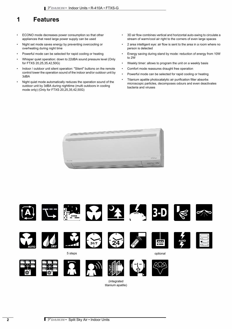
1 Features
Indoor Units Indoor Units Split Sky Air FTXS-G R-410A • ECONO mode decreases power consumption so that other appliances that need large power supply can be used
• Night set mode saves energy by preventing overcooling or overheating during night time
• Powerful mode can be selected for rapid cooling or heating
• Whisper quiet operation: down to 22dBA sound pressure level (Only for FTXS 20,25,35,42,50G)
• Indoor / outdoor unit silent operation: "Silent" buttons on the remote control lower the operation sound of the indoor and/or outdoor unit by 3dBA
• Night quiet mode automatically reduces the operation sound of the outdoor unit by 3dBA during nighttime (multi outdoors in cooling mode only) (Only for FTXS 20,25,35,42,50G)
• 3D air flow combines vertical and horizontal auto-swing to circulate a stream of warm/cool air right to the corners of even large spaces
• 2 area intelligent eye: air flow is sent to the area in a room where no person is detected
• Energy saving during stand by mode: reduction of energy from 10W to 2W
• Weekly timer: allows to program the unit on a weekly basis
• Comfort mode reassures draught free operation
• Powerful mode can be selected for rapid cooling or heating
• Titanium apatite photocatalytic air purification filter absorbs microscopic particles, decomposes odours and even deactivates bacteria and viruses
5 steps optional
(integrated titanium apatite)
FTXS-G_EN.book Page 2 Wednesday, May 12, 2010 8:28 AM
• Split Sky Air • Indoor Units 3
• Indoor Units • R-410A • FTXS-G
2 Specifications
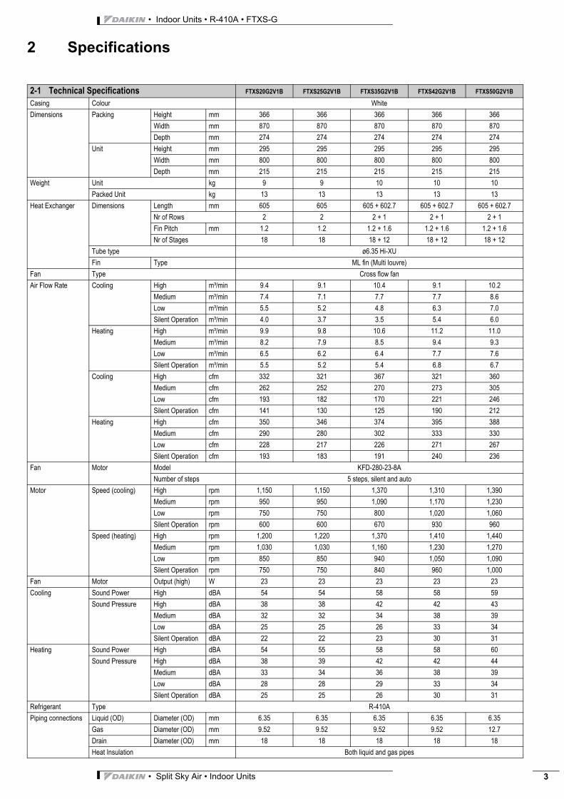
2-1 Technical Specifications FTXS20G2V1B FTXS25G2V1B FTXS35G2V1B FTXS42G2V1B FTXS50G2V1B
Casing Colour White
Dimensions Packing Height mm 366 366 366 366 366
Width mm 870 870 870 870 870
Depth mm 274 274 274 274 274
Unit Height mm 295 295 295 295 295
Width mm 800 800 800 800 800
Depth mm 215 215 215 215 215
Weight Unit kg 9 9 10 10 10
Packed Unit kg 13 13 13 13 13
Heat Exchanger Dimensions Length mm 605 605 605 + 602.7 605 + 602.7 605 + 602.7
Nr of Rows 2 2 2 + 1 2 + 1 2 + 1
Fin Pitch mm 1.2 1.2 1.2 + 1.6 1.2 + 1.6 1.2 + 1.6
Nr of Stages 18 18 18 + 12 18 + 12 18 + 12
Tube type ø6.35 Hi-XU
Fin Type ML fin (Multi louvre)
Fan Type Cross flow fan
Air Flow Rate Cooling High m³/min 9.4 9.1 10.4 9.1 10.2
Medium m³/min 7.4 7.1 7.7 7.7 8.6
Low m³/min 5.5 5.2 4.8 6.3 7.0
Silent Operation m³/min 4.0 3.7 3.5 5.4 6.0
Heating High m³/min 9.9 9.8 10.6 11.2 11.0
Medium m³/min 8.2 7.9 8.5 9.4 9.3
Low m³/min 6.5 6.2 6.4 7.7 7.6
Silent Operation m³/min 5.5 5.2 5.4 6.8 6.7
Cooling High cfm 332 321 367 321 360
Medium cfm 262 252 270 273 305
Low cfm 193 182 170 221 246
Silent Operation cfm 141 130 125 190 212
Heating High cfm 350 346 374 395 388
Medium cfm 290 280 302 333 330
Low cfm 228 217 226 271 267
Silent Operation cfm 193 183 191 240 236
Fan Motor Model KFD-280-23-8A
Number of steps 5 steps, silent and auto
Motor Speed (cooling) High rpm 1,150 1,150 1,370 1,310 1,390
Medium rpm 950 950 1,090 1,170 1,230
Low rpm 750 750 800 1,020 1,060
Silent Operation rpm 600 600 670 930 960
Speed (heating) High rpm 1,200 1,220 1,370 1,410 1,440
Medium rpm 1,030 1,030 1,160 1,230 1,270
Low rpm 850 850 940 1,050 1,090
Silent Operation rpm 750 750 840 960 1,000
Fan Motor Output (high) W 23 23 23 23 23
Cooling Sound Power High dBA 54 54 58 58 59
Sound Pressure High dBA 38 38 42 42 43
Medium dBA 32 32 34 38 39
Low dBA 25 25 26 33 34
Silent Operation dBA 22 22 23 30 31
Heating Sound Power High dBA 54 55 58 58 60
Sound Pressure High dBA 38 39 42 42 44
Medium dBA 33 34 36 38 39
Low dBA 28 28 29 33 34
Silent Operation dBA 25 25 26 30 31
Refrigerant Type R-410A
Piping connections Liquid (OD) Diameter (OD) mm 6.35 6.35 6.35 6.35 6.35
Gas Diameter (OD) mm 9.52 9.52 9.52 9.52 12.7
Drain Diameter (OD) mm 18 18 18 18 18
Heat Insulation Both liquid and gas pipes
FTXS-G_EN.book Page 3 Wednesday, May 12, 2010 8:28 AM

• Indoor Units • R-410A • FTXS-G
• Split Sky Air • Indoor Units4
2 Specifications
Air Filter Removable/washable/Mildew proof
Air direction control Right, Left, Horizontal, Downward
Temperature control Microcomputer control
Standard Accessories
Item Titanium apatite photocatalytic air purification filter
Quantity 2 2 2 2 2
Item Operation manual
Quantity 1 1 1 1 1
Item Installation manual
Quantity 1 1 1 1 1
Item Wireless remote control
Quantity 1 1 1 1 1
Item Batteries
Quantity 2 2 2 2 2
Item Remote control holder
Quantity 1 1 1 1 1
Item Indoor unit fixing screws
Quantity 2 2 2 2 2
Item Mounting plate
Quantity 1 1 1 1 1
2-1 Technical Specifications FTXS60GV1B FTXS71GV1B
Casing Colour White
Dimensions Packing Height mm 361 361
Width mm 1,145 1,145
Depth mm 364 364
Unit Height mm 290 290
Width mm 1,050 1,050
Depth mm 250 250
Weight Unit kg 12 12
Packed Unit kg 18 18
Heat Exchanger Dimensions Length mm 863 863
Nr of Rows 2 2
Fin Pitch mm 1.4 1.4
Nr of Stages 16 16
Tube type ø7 Hi-XD
Fin Type ML fin (Multi louver)
Fan Type Cross flow fan
Air Flow Rate Cooling High m³/min 16.0 17.2
Medium m³/min 13.5 14.5
Low m³/min 11.3 11.5
Silent Operation m³/min 10.1 10.5
Heating High m³/min 17.2 19.5
Medium m³/min 14.9 16.7
Low m³/min 12.6 14.2
Silent Operation m³/min 11.3 12.6
Cooling High cfm 565 607
Medium cfm 447 512
Low cfm 399 406
Silent Operation cfm 357 371
Heating High cfm 607 689
Medium cfm 526 590
Low cfm 445 501
Silent Operation cfm 399 445
Fan Motor Model ARW3001DA
Number of steps 5 steps, silent and auto
2-1 Technical Specifications FTXS20G2V1B FTXS25G2V1B FTXS35G2V1B FTXS42G2V1B FTXS50G2V1B
FTXS-G_EN.book Page 4 Wednesday, May 12, 2010 8:28 AM

• Split Sky Air • Indoor Units 5
• Indoor Units • R-410A • FTXS-G
2 Specifications
Motor Speed (cooling) High rpm 1,330 1,410
Medium rpm 1,170 1,220
Low rpm 1,010 1,040
Silent Operation rpm 920 950
Speed (heating) High rpm 1,360 1,520
Medium rpm 1,200 1,330
Low rpm 1,040 1,150
Silent Operation rpm 950 1,040
Fan Motor Output (high) W 43 43
Cooling Sound Power High dBA 61 62
Sound Pressure High dBA 45 46
Medium dBA 41 42
Low dBA 36 37
Silent Operation dBA 33 34
Heating Sound Power High dBA 60 62
Sound Pressure High dBA 44 46
Medium dBA 40 42
Low dBA 35 37
Silent Operation dBA 32 34
Air Filter Removable/washable/Mildew proof
Air direction control Right, Left, Horizontal, Downward
Temperature control Microcomputer control
Standard Accessories
Item Titanium apatite photocatalytic air purification filter
Quantity 2
Item Operation manual
Quantity 1
Item Installation manual
Quantity 1
Item Infrared remote control
Quantity 1
Item Batteries
Quantity 2
Item Remote control holder
Quantity 1
Item Indoor unit fixing screws
Quantity 2
Item Mounting plate
Quantity 1
2-1 Electrical Specifications FTXS20G2V1B FTXS25G2V1B FTXS35G2V1B FTXS42G2V1B FTXS50G2V1B
Power Supply Name V1
Phase 1~
Frequency Hz 50 50 50 50 50
Voltage V 220-230-240
Current Nominal running current (RLA)
Cooling A 0.09-0.08-0.08 0.09-0.08-0.08 0.12-0.12-0.11 0.11-0.11-0.10 0.12-0.12-0.11
Heating A 0.10-0.10-0.09 0.10-0.10-0.09 0.13-0.13-0.12 0.14-0.14-0.13 0.15-0.14-0.14
Wiring connections For Power Supply Quantity 3 3 3 3 3
2-2 Electrical Specifications FTXS60GV1B FTXS71GV1B
Power Supply Name V1
Phase 1~
Frequency Hz 50
Voltage V 220-240
Current Nominal running current (RLA)
Cooling A 0.18 0.20
Heating A 0.20 0.27
Wiring connections For Power Supply Quantity 3 for power supply, 4 for interunit wiring (Earth wire included)
2-1 Technical Specifications FTXS60GV1B FTXS71GV1B
FTXS-G_EN.book Page 5 Wednesday, May 12, 2010 8:28 AM

• Indoor Units • R-410A • FTXS-G
• Split Sky Air • Indoor Units6
3 Dimensional drawing & centre of gravity
3 - 1 Dimensional drawingFTXS20-42G
3D058919A
Air flow (Indoor)The mark (→) shows piping direction
50 Min
Space for maintenance
Space for maintenance
50 Min
REQUIRED SPACE
30 M
in
Spa
ce fo
r pe
rform
ance
Gas pipe Ø9.5 CuT
(The length of pipe outside the unit: about 350) Liquid pipe Ø6.4 CuT
(The length of pipe outside the unit: about 400)
Drain hose
(Connecting part
I.D. Ø14
O.D. Ø18
The hose length of outside the unit is approx. 465)
Wall hole for embedded piping
Ø65 hole Wall hole
Ø65 hole
STANDARD LOCATIONS OF WALL HOLES
Right/left (automatic)
Heating FanCooling, dry
INFRARED REMOTE CONTROL
(ARC452A3)
Signal transmitter
Model name plate
BLADE ANGLES
Left Right
Rear
Front panel fixed screws
(inside)
BottomFlaps
Signal receiverIntelligent eye sensor
Operation lamp
Timer lamp
Intelligent eye lamp
Indoor unit ON/OFF switch
Room temp. thermistor (Inside)
Terminal block with earth terminal
Name plate
Including mounting plate
Up/down
(Automatic)
FTXS50G
3D058920A
Air flow (Indoor)The mark (→) shows piping direction
50 Min
Space for maintenance
Space for maintenance
50 Min
REQUIRED SPACE
30 M
in
Spa
ce fo
r pe
rform
ance
Gas pipe Ø12.7 CuT
(The length of pipe outside the unit: about 350) Liquid pipe Ø6.4 CuT
(The length of pipe outside the unit: about 400)
Drain hose
(Connecting part
I.D. Ø14
O.D. Ø18
The hose length of outside the unit is approx. 465)
Wall hole for embedded piping
Ø65 hole Wall hole
Ø65 hole
STANDARD LOCATIONS OF WALL HOLES
Right/left (automatic)
Heating FanCooling, dry
INFRARED REMOTE CONTROL
(ARC452A3)
Signal transmitterModel name plate
BLADE ANGLES
Left Right
Rear
Front panel fixed screws
(inside)
BottomFlaps
Signal receiverIntelligent eye sensor
Operation lamp
Timer lamp
Intelligent eye lamp
Indoor unit ON/OFF switch
Room temp. thermistor (Inside)
Terminal block with earth terminal
Name plate
Including mounting plate
Up/down
(Automatic)
FTXS-G_EN.book Page 6 Wednesday, May 12, 2010 8:28 AM

• Split Sky Air • Indoor Units 7
• Indoor Units • R-410A • FTXS-G
3 Dimensional drawing & centre of gravity
3 - 1 Dimensional drawing
FTXS60GV
3D065514
The mark
Left
Bottom
Rear Rear Right
Model name plate
(Includinginstallation plate)
Terminal block with earth terminal (inside)
Wall hole for embedded piping
ø 80 holeInfrared remote control
(ARC452A3)
Signaltransmitter
Front grille fixing screws(inside)
Flaps
Operation lamp
Signal receiver
Indoor unit on/off switch
Room temp. thermistor (inside)
Intelligent eye sensor
Intelligent eye lamp
Timer lamp
Model name plate
Horizontal blade(automatic)
Cooling Heating Dry
Vertical blade (automatic)Fan
Wall hole ø 80 hole
STANDARD LOCATIONS OF WALL HOLES
BLADE ANGLES
Gas pipe ø12.7 CuT(the length of pipe outside
the unit: about 430)
Liquid pipe ø6.4 CuT(the length of pipe outside the
unit: about 480)
Drain hose for VP13(connecting part I.D. 14.0, O.D. 18.0)
(The hose length of outside the unit: about 530)
Min. 50
(Space for
maintenance)
Min. 50
(Space for
maintenance)
Min
. 30
(Spa
ce fo
r
perf
orm
ance
)
REQUIRED SPACE
Air flow (indoor)(For performance and maintenance)
shows piping direction
FTXS71GV
3D065515
The mark
Left
Bottom
Rear Rear Right
Model name plate
(Includinginstallation plate)
Terminal block with earth terminal (inside)
Wall hole for embedded piping
ø 80 holeInfrared remote control
(ARC452A3)
Signaltransmitter
Front grille fixing screws(inside)
Flaps
Operation lamp
Signal receiver
Indoor unit on/off switch
Room temp. thermistor (inside)
Intelligent eye sensor
Intelligent eye lamp
Timer lamp
Model name plate
Horizontal blade(automatic)
Cooling Heating Dry
Vertical blade (automatic)Fan
Wall hole ø 80 hole
STANDARD LOCATIONS OF WALL HOLES
BLADE ANGLES
Gas pipe ø15.9 CuT(the length of pipe outside
the unit: about 430)
Liquid pipe ø6.4 CuT(the length of pipe outside
the unit: about 480)
Drain hose for VP13(connecting part I.D. 14.0, O.D. 18.0)
(The hose length of outside the unit: about 530)
Min. 50
(Space for
maintenance)
Min. 50
(Space for
maintenance)
Min
. 30
(Spa
ce fo
r
perf
orm
ance
)
REQUIRED SPACE
Air flow (indoor)(For performance and maintenance)
shows piping direction
FTXS-G_EN.book Page 7 Wednesday, May 12, 2010 8:28 AM

• Indoor Units • R-410A • FTXS-G
• Split Sky Air • Indoor Units8
3 Dimensional drawing & centre of gravity
3 - 2 Centre of gravityFTXS20-50G
4D059112B
FTXS60-71GV
4D065274
FTXS-G_EN.book Page 8 Wednesday, May 12, 2010 8:28 AM

• Split Sky Air • Indoor Units 9
• Indoor Units • R-410A • FTXS-G
4 Piping diagram
FTXS20-42G
4D058897C
INDOOR UNIT
Heat exchanger
Thermistor on heat exch.
Fan motor
Cross flow fan
Field piping
Field piping
9.5CuT9.5CuT
6.4CuT
Refrigerant flow
Cooling
Heating
6.4CuT
FTXS50G
4D058898C
INDOOR UNIT
Heat exchanger
Thermistor on heat exch.
Fan motor
Cross flow fan
Field piping
Field piping
9.5CuT12.7CuT
6.4CuT
Refrigerant flow
Cooling
Heating
6.4CuT
FTXS-G_EN.book Page 9 Wednesday, May 12, 2010 8:28 AM

• Indoor Units • R-410A • FTXS-G
• Split Sky Air • Indoor Units10
4 Piping diagram
FTXS60GV
4D040081V
Indoor unit
(7.9 CuT)
Cross flow fan
Refrigerant flow
Fan motor
(12.7 CuT)
Heat exchanger
Thermistor on heat exch.
Cooling
Heating
Field piping
Field piping
(6.4 CuT)
(12.7 CuT)
FTXS71GV
4D040082T
Indoor unit
(7.9 CuT)
Cross flow fan
Refrigerant flow
Fan motor
(12.7 CuT)
Heat exchanger
Thermistor on heat exch.
Cooling
Heating
Field piping
Field piping
(6.4 CuT)
(15.9 CuT)
FTXS-G_EN.book Page 10 Wednesday, May 12, 2010 8:28 AM

• Split Sky Air • Indoor Units 11
• Indoor Units • R-410A • FTXS-G
5 Wiring diagram
5 - 1 Wiring diagram
FTXS20-50G
3D058246
INFRARED REMOTE
CONTROL
: Frame ground
: Fuse
: Pilot lamp
: Fan motor
: Swing motor
: Printed circuit board
: Thermistor
: Connector
: Operation switch
: Terminal switch
: Protective earth
RECTIFIER
TRANSMISSION CIRCUIT
WIRING DIAGRAM
FG
F1U
H1P~H3P
M1F
M1S~M3S
PCB1~PCB4
R1T, R2T
S1~S49
S1W
X1M
CAUTION
Note that operation will restart automatically if the main power supply is turned off and than back on again.
FIELD WIRING
INDOOR
INTELLIGENT EYE SENSOR
SIGNAL RECEIVER
OUTDOOR
B
FTXS60-71GV
3D064800
FG Frame ground R1T,R2T Thermistor
F1U Fuse S1~S49 Connector
H1P~H3P Pilot lamp SW1 Operation switch
M1F Fan motor X1M Terminal strip
M1S, M2S Swing motor Protective earth
PCB1~PCB4 Printed circuit board
LED1H1P
LED2H2P
LED3H3P
Transmissioncircuit
Intelligent eye sensor
Signalreceiver
Indoorinfraredremotecontrol
Field wiring
Outdoor
CAUTION
Note that operation will restart automatically if the main power supply is turned off and then back on again.
FTXS-G_EN.book Page 11 Wednesday, May 12, 2010 8:28 AM

• Indoor Units • R-410A • FTXS-G
• Split Sky Air • Indoor Units12
6 Sound data
6 - 1 Sound pressure spectrum
3D059555
NOTES
1 220-240V 50 Hz : 50 Hz 220-240V (H): 50 Hz 220-240V (L)
Cooling2 Measure in anechoic room3 Location of microphone
4 Operation noise differs with operation and ambient conditions.
Oct
ave
band
sou
nd p
ress
ure
leve
l d
B(0
dB=0
.000
2μba
r)
Approximate threshold hearing for continuous noise
FTXS20G COOLING
Octave band center frequency (Hz)
1m
0.8m
3D059555
NOTES
1 220-240V 50 Hz : 50 Hz 220-240V (H): 50 Hz 220-240V (L)
Heating2 Measure in anechoic room3 Location of microphone
4 Operation noise differs with operation and ambient conditions.
Oct
ave
band
sou
nd p
ress
ure
leve
l d
B(0
dB=0
.000
2μba
r)
Approximate threshold hearing for continuous noise
FTXS20G HEATING
Octave band center frequency (Hz)
1m
0.8m
3D059556B
NOTES
1 220-240V 50 Hz : 50 Hz 220-240V (H): 50 Hz 220-240V (L)
Cooling2 Measure in anechoic room3 Location of microphone
4 Operation noise differs with operation and ambient conditions.
Oct
ave
band
sou
nd p
ress
ure
leve
l d
B(0
dB=0
.000
2μba
r)
Approximate threshold hearing for continuous noise
FTXS25G COOLING
Octave band center frequency (Hz)
1m
0.8m
3D059556B
NOTES
1 220-240V 50 Hz : 50 Hz 220-240V (H): 50 Hz 220-240V (L)
Heating2 Measure in anechoic room3 Location of microphone
4 Operation noise differs with operation and ambient conditions.
Oct
ave
band
sou
nd p
ress
ure
leve
l d
B(0
dB=0
.000
2μba
r)
Approximate threshold hearing for continuous noise
FTXS25G HEATING
Octave band center frequency (Hz)
1m
0.8m
FTXS-G_EN.book Page 12 Wednesday, May 12, 2010 8:28 AM

• Split Sky Air • Indoor Units 13
• Indoor Units • R-410A • FTXS-G
6 Sound data
6 - 1 Sound pressure spectrum
3D059557C
NOTES
1 220-240V 50 Hz : 50 Hz 220-240V (H): 50 Hz 220-240V (L)
Cooling2 Measure in anechoic room3 Location of microphone
4 Operation noise differs with operation and ambient conditions.
Oct
ave
band
sou
nd p
ress
ure
leve
l d
B(0
dB=0
.000
2μba
r)
Approximate threshold hearing for continuous noise
FTXS35G COOLING
Octave band center frequency (Hz)
1m
0.8m
3D059557C
NOTES
1 220-240V 50 Hz : 50 Hz 220-240V (H): 50 Hz 220-240V (L)
Heating2 Measure in anechoic room3 Location of microphone
4 Operation noise differs with operation and ambient conditions.
Oct
ave
band
sou
nd p
ress
ure
leve
l d
B(0
dB=0
.000
2μba
r)
Approximate threshold hearing for continuous noise
FTXS35G HEATING
Octave band center frequency (Hz)
1m
0.8m
3D059558B
NOTES
1 220-240V 50 Hz : 50 Hz 220-240V (H): 50 Hz 220-240V (L)
Cooling2 Measure in anechoic room3 Location of microphone
4 Operation noise differs with operation and ambient conditions.
Oct
ave
band
sou
nd p
ress
ure
leve
l d
B(0
dB=0
.000
2μba
r)
Approximate threshold hearing for continuous noise
FTXS42G COOLING
Octave band center frequency (Hz)
1m
0.8m
3D059558B
NOTES
1 220-240V 50 Hz : 50 Hz 220-240V (H): 50 Hz 220-240V (L)
Heating2 Measure in anechoic room3 Location of microphone
4 Operation noise differs with operation and ambient conditions.
Oct
ave
band
sou
nd p
ress
ure
leve
l d
B(0
dB=0
.000
2μba
r)
Approximate threshold hearing for continuous noise
FTXS42G HEATING
Octave band center frequency (Hz)
1m
0.8m
FTXS-G_EN.book Page 13 Wednesday, May 12, 2010 8:28 AM

• Indoor Units • R-410A • FTXS-G
• Split Sky Air • Indoor Units14
6 Sound data
6 - 1 Sound pressure spectrum
3D059559B
NOTES
1 220-240V 50 Hz : 50 Hz 220-240V (H): 50 Hz 220-240V (L)
Cooling2 Measure in anechoic room3 Location of microphone
4 Operation noise differs with operation and ambient conditions.
Oct
ave
band
sou
nd p
ress
ure
leve
l d
B(0
dB=0
.000
2μba
r)
Approximate threshold hearing for continuous noise
FTXS50G COOLING
Octave band center frequency (Hz)
1m
0.8m
3D059559B
NOTES
1 220-240V 50 Hz
: 50 Hz 220-240V (H)
: 50 Hz 220-240V (L)
Heating
2 Measure in anechoic room
3 Location of microphone
4 Operation noise differs with operation and ambient conditions.
Oct
ave
band
sou
nd p
ress
ure
leve
l d
B(0
dB=0
.000
2μba
r)
Approximate threshold hearing for continuous noise
FTXS50G HEATING
Octave band center frequency (Hz)
1m
0.8m
FTXS60GV
3D051227D
NOTES
1 Over All (dB):
(B,G,N is already rectified)
2 Measuring place: measure in anechoic room.
3 Operation noise differs with operation and ambient conditions.
4 Location of microphone.
JISC9612
The operation noise
measuring method is in
accordance with JISC9612
NOTES
1 Over All (dB):
(B,G,N is already rectified)
2 Measuring place: measure in anechoic room.
3 Operation noise differs with operation and ambient conditions.
4 Location of microphone.
JISC9612
The operation noise
measuring method is in
accordance with JISC9612
Oct
ave
band
sou
nd p
ress
ure
leve
l dB
(0
dB =
0.0
002μ
bar
)
Oct
ave
band
sou
nd p
ress
ure
leve
l dB
(0
dB =
0.0
002μ
bar
)
Octave band center frequency - IEC (Hz) Octave band center frequency - IEC (Hz)
Scale
50Hz220-240V
(H) (L)
A 45 36
Scale
50Hz220-240V
H L
A 44 35
Cooling Heating
Approximatethreshold hearing for continuous noise
Approximatethreshold hearing for continuous noise
1m 1m
0.8m
0.8m
FTXS-G_EN.book Page 14 Wednesday, May 12, 2010 8:28 AM

• Split Sky Air • Indoor Units 15
• Indoor Units • R-410A • FTXS-G
6 Sound data
6 - 1 Sound pressure spectrum
FTXS71GV
3D051225D
NOTES
1 Over All (dB):
(B,G,N is already rectified)
2 Measuring place: measure in anechoic room.
3 Operation noise differs with operation and ambient conditions.
4 Location of microphone.
JISC9612
The operation noise
measuring method is in
accordance with JISC9612
NOTES
1 Over All (dB):
(B,G,N is already rectified)
2 Measuring place: measure in anechoic room.
3 Operation noise differs with operation and ambient conditions.
4 Location of microphone.
JISC9612
The operation noise
measuring method is in
accordance with JISC9612
Oct
ave
band
sou
nd p
ress
ure
leve
l dB
(0
dB =
0.0
002μ
bar
)
Oct
ave
band
sou
nd p
ress
ure
leve
l dB
(0
dB =
0.0
002μ
bar
)
Octave band center frequency - IEC (Hz) Octave band center frequency - IEC (Hz)
Scale
50Hz220-240V
(H) (L)
A 46 37
Scale
50Hz220-240V
(H) (L)
A 46 37
Cooling Heating
Approximatethreshold hearing for continuous noise
Approximatethreshold hearing for continuous noise
1m 1m
0.8m
0.8m
FTXS-G_EN.book Page 15 Wednesday, May 12, 2010 8:28 AM

Naamloze Vennootschap - Zandvoordestraat 300, B-8400 Oostende - Belgium - www.daikin.eu - BE 0412 120 336 - RPR Oostende
Daikin’s unique position as a manufacturer of air conditioning equipment, compressors and refrigerants has led to its close involvement in environmental issues. For several years Daikin has had the intention to become a leader in the provision of products that have limited impact on the environment. This challenge demands the eco design and development of a wide range of products and an energy management system, resulting in energy conservation and a reduction of waste.
Daikin Europe N.V. is participating in the EUROVENT Certification Programme. Products are as listed in the EUROVENT Directory of Certified Products.
Daikin products are distributed by:
EED
EN10
-100
• C
D •
05/1
0 • C
opyr
ight
Dai
kin
Prep
ared
in B
elgi
um b
y La
nnoo
(ww
w.la
nnoo
prin
t.be)
, a c
ompa
ny w
hose
con
cern
fo
r the
env
ironm
ent i
s set
in th
e EM
AS a
nd IS
O 1
4001
syst
ems.
Resp
onsi
ble
Edito
r: D
aiki
n Eu
rope
N.V
., Za
ndvo
orde
stra
at 3
00, B
-840
0 O
oste
nde
The present publication is drawn up by way of information only and does not constitute an offer binding upon Daikin Europe N.V.. Daikin Europe N.V. has compiled the content of this publication to the best of its knowledge. No express or implied warranty is given for the completeness, accuracy, reliability or fitness for particular purpose of its content and the products and services presented therein. Specifications are subject to change without prior notice. Daikin Europe N.V. explicitly rejects any liability for any direct or indirect damage, in the broadest sense, arising from or related to the use and/or interpretation of this publication. All content is copyrighted by Daikin Europe N.V..