
Air-Conditioners PUMY-P112, P125, P140VKM2 PUMY-P112, … · Para un uso correcto y seguro, lea...
44
0217g5ødø1 ȾɅəɍɋɌȺɇɈȼɂɌȿɅə TIL INSTALLATØREN FÖR INSTALLATÖREN PARA O INSTALADOR īǿǹ ǹȊȉȅȃ ȆȅȊ ȀǹȃǼǿ ȉǾȃ ǼīȀǹȉǹȈȉǹȈǾ PER L’INSTALLATORE PARA EL INSTALADOR VOOR DE INSTALLATEUR POUR L’INSTALLATEUR FÜR INSTALLATEURE FOR INSTALLER Air-Conditioners PUMY-P112, P125, P140VKM2 PUMY-P112, P125, P140YKM2 PUMY-P112, P125, P140YKME2 For use with R410A EȜȜȘȞȚțȐ *R INSTALLATION MANUAL For safe and correct use, read this manual and the indoor unit installation manual thoroughly before installing the air-conditioner unit. ɊɍɄɈȼɈȾɋɌȼɈ ɉɈ ɍɋɌȺɇɈȼɄȿ Ⱦɥɹ ɨɛɟɫɩɟɱɟɧɢɹ ɛɟɡɨɩɚɫɧɨɣ ɢ ɧɚɞɥɟɠɚɳɟɣ ɷɤɫɩɥɭɚɬɚɰɢɢ ɜɧɢɦɚɬɟɥɶɧɨ ɩɪɨɱɬɢɬɟ ɞɚɧɧɨɟ ɪɭɤɨɜɨɞɫɬɜɨ ɢ ɪɭɤɨɜɨɞɫɬɜɨ ɩɨ ɭɫɬɚɧɨɜɤɟ ɜɧɭɬɪɟɧɧɟɝɨ ɩɪɢɛɨɪɚ ɩɟɪɟɞ ɭɫɬɚɧɨɜɤɨɣ ɤɨɧɞɢɰɢɨɧɟɪɚ. INSTALLATIONSHANDBUCH Aus Sicherheitsgründen und zur richtigen Verwendung vor der Installation die vorliegende Bedienungsanleitung und die Installationsanleitung der Innenanlage gründlich durchlesen die Klimaanlage. MANUEL D’INSTALLATION Avant d’installer le climatiseur, lire attentivement ce manuel, ainsi que le manuel d’installation de l’appareil intérieur pour une utilisation sûre et correcte. INSTALLATIEHANDLEIDIN* Lees deze handleiding en de installatiehandleiding van het binnenapparaat zorgvuldig door voordat u met het installeren van de airconditioner begint. MANUAL DE INSTALACIÓN Para un uso correcto y seguro, lea detalladamente este manual y el manual de instalación de la unidad interior antes de instalar la unidad de aire acondicionado. MANUALE DI INSTALLAZIONE Per un uso sicuro e corretto, leggere attentamente il presente manuale ed il manuale d’installazione dell’unità interna prima di installare il condizionatore d’aria. EīȋEIPIǻIO OǻHīIȍN EīKATAȈTAȈHȈ īȚĮ ıȦıIJȒ țĮȚ ĮıijĮȜȒ ȤȡȒıȘ, įȚĮȕȐıIJİ ʌȡȠıİțIJȚțȐ ĮȣIJȩ IJȠ İȖȤİȚȡȓįȚȠ țĮșȫȢ țĮȚ IJȠ İȖȤİȚȡȓįȚȠ İȖțĮIJȐıIJĮıȘȢ IJȘȢ İıȦIJİȡȚțȒȢ ȝȠȞȐįĮȢ, ʌȡȠIJȠȪ İȖțĮIJĮıIJȒıİIJİ IJȘ ȝȠȞȐįĮ IJȠȣ țȜȚȝĮIJȚıIJȚțȠȪ. MANUAL DE INSTALAdO Para uma utilização segura e correcta, leia atentamente este manual e o manual de instalação da unidade interior antes de instalar o aparelho de ar condicionado. INSTALLATIONSMANUAL Læs af sikkerhedshensyn denne manual samt manualen til installation af indendørsenheden grundigt, før du installerer klimaanlægget. INSTALLATIONSMANUAL Läs bruksanvisningen och inomhusenhetens installationshandbok noga innan luftkonditioneringen installeras så att den används på ett säkert och korrekt sätt. MONTA- ELKøTABI (mniyetli ve do÷ru kullanÕm için, klima cihazÕnÕ monte etmeden |nce bu kÕlavuzu ve iç ünite montaM kÕlavuzunu tamamÕyla okuyun. TrNoe TR Ɋɭɫɫɤɢɣ RU EnJOish *B DeutsFh D FrDnoDis F NederODnds NL EsSDxoO E ItDOiDno I PortuJurs P DDnsN DA SYensND S:
Transcript of Air-Conditioners PUMY-P112, P125, P140VKM2 PUMY-P112, … · Para un uso correcto y seguro, lea...

TIL INSTALLATØREN
FÖR INSTALLATÖREN
PARA O INSTALADOR
PER L’INSTALLATORE
PARA EL INSTALADOR
VOOR DE INSTALLATEUR
POUR L’INSTALLATEUR
FÜR INSTALLATEURE
FOR INSTALLER
Air-ConditionersPUMY-P112, P125, P140VKM2PUMY-P112, P125, P140YKM2PUMY-P112, P125, P140YKME2
For use with R410A
E R
INSTALLATION MANUALFor safe and correct use, read this manual and the indoor unit installation manual thoroughly before installing the air-conditioner unit.
.
INSTALLATIONSHANDBUCHAus Sicherheitsgründen und zur richtigen Verwendung vor der Installation die vorliegende Bedienungsanleitung und die Installationsanleitung der Innenanlage gründlich durchlesen die Klimaanlage.
MANUEL D’INSTALLATIONAvant d’installer le climatiseur, lire attentivement ce manuel, ainsi que le manuel d’installation de l’appareil intérieur pour une utilisation sûre et correcte.
INSTALLATIEHANDLEIDINLees deze handleiding en de installatiehandleiding van het binnenapparaat zorgvuldig door voordat u met het installeren van de airconditioner begint.
MANUAL DE INSTALACIÓNPara un uso correcto y seguro, lea detalladamente este manual y el manual de instalación de la unidad interior antes de instalar la unidad de aire acondicionado.
MANUALE DI INSTALLAZIONEPer un uso sicuro e corretto, leggere attentamente il presente manuale ed il manuale d’installazione dell’unità interna prima di installare il condizionatore d’aria.
E EIPI IO O H I N E KATA TA H , , .
MANUAL DE INSTALA OPara uma utilização segura e correcta, leia atentamente este manual e o manual de instalação da unidade interior antes de instalar o aparelho de ar condicionado.
INSTALLATIONSMANUALLæs af sikkerhedshensyn denne manual samt manualen til installation af indendørsenheden grundigt, før du installerer klimaanlægget.
INSTALLATIONSMANUALLäs bruksanvisningen och inomhusenhetens installationshandbok noga innan luftkonditioneringen installeras så att den används på ett säkert och korrekt sätt.
MONTA ELK TABImniyetli ve do ru kullan m için, klima cihaz n monte etmeden nce bu k lavuzu ve iç ünite monta k lavuzunu
tamam yla okuyun.T r e TR
RU
En ish B
Deuts h D
Fr n is F
Neder nds NL
Es o E
It i no I
Portu u s P
D ns DA
S ens S

2
Warning: The unit ust not e insta ed the user As a dea er or an authori ed te hni ian to insta the unit I the unit is insta ed in orre t , water ea age, e e tri sho , or re a resu t
This a ian e is intended to e used e ert or trained users in sho s, in ight industr and on ar s, or or o er ia use a ersons
For insta ation wor , o ow the instru tions in the Insta ation Manua and use too s and i e o onents s e i a ade or use with R410A re rig-erant The R410A re rigerant in the HFC s ste is ressuri ed 1 ti es the
ressure o usua re rigerants I i e o onents not designed or R410A re rigerant are used and the unit is not insta ed orre t , the i es a urst and ause da age or in uries In addition, water ea age, e e tri sho , or
re a resu t The unit ust e insta ed a ording to the instru tions in order to ini i e the ris o da age ro earth ua es, t hoons, or strong winds An in or-re t insta ed unit a a down and ause da age or in uries
The unit ust e se ure insta ed on a stru ture that an sustain its weight I the unit is ounted on an unsta e stru ture, it a a down and ause da age or in uries
I the air onditioner is insta ed in a s a roo , easures ust e ta en to re ent the re rigerant on entration in the roo ro e eeding the sa et
i it in the e ent o re rigerant ea age Consu t a dea er regarding the a ro-riate easures to re ent the a owa e on entration ro eing e eeded
Shou d the re rigerant ea and ause the on entration i it to e e eeded, ha ards due to a o o gen in the roo a resu t
Venti ate the roo i re rigerant ea s during o eration I re rigerant o es into onta t with a a e, oisonous gases wi e re eased
A e e tri wor ust e er or ed a ua i ed te hni ian a ording to o a regu ations and the instru tions gi en in this anua The units ust e owered dedi ated ower ines and the orre t o tage and ir uit rea ers ust e used Power ines with insu ient a a it or in orre t e e tri a
wor a resu t in e e tri sho or re Use C1220 o er hos horus, or o er and o er a o sea ess i es, to onne t the re rigerant i es I the i es are not onne ted orre t , the unit wi not e ro er grounded and e e tri sho a resu t
Use on s e i ed a es or wiring The wiring onne tions ust e ade se ure with no tension a ied on the ter ina onne tions A so, ne er s i e the a es or wiring un ess otherwise indi ated in this do u ent
Fai ure to o ser e these instru tions a resu t in o erheating or a re The ter ina o o er ane o the outdoor unit ust e r atta hed I the o er ane is ounted in orre t and dust and oisture enter the unit, e e tri sho or re a resu t
When insta ing or re o ating, or ser i ing the air onditioner, use on the s e i ed re rigerant R410A to harge the re rigerant ines Do not i it with an other re rigerant and do not a ow air to re ain in the ines
I air is i ed with the re rigerant, then it an e the ause o a nor a high ressure in the re rigerant ine, and a resu t in an e osion and other
ha ards The use o an re rigerant other than that s e i ed or the s ste wi ause
e hani a ai ure or s ste a un tion or unit rea down In the worst ase, this ou d ead to a serious i edi ent to se uring rodu t sa et
Use on a essories authori ed Mitsu ishi E e tri and as a dea er or an authori ed te hni ian to insta the I a essories are in orre t insta ed, water ea age, e e tri sho , or re a resu t
Do not a ter the unit Consu t a dea er or re airs I a terations or re airs are not er or ed orre t , water ea age, e e tri sho , or re a resu t
The user shou d ne er atte t to re air the unit or trans er it to another o a-tion I the unit is insta ed in orre t , water ea age, e e tri sho , or re
a resu t I the air onditioner ust e re aired or o ed, as a dea er or an authori ed te hni ian
A ter insta ation has een o eted, he or re rigerant ea s I re riger-ant ea s into the roo and o es into onta t with the a e o a heater or
orta e oo ing range, oisonous gases wi e re eased
1 Sa et re autions
Be ore insta ing the unit, a e sure ou read a the Sa et re au-tions
P ease re ort to or ta e onsent the su authorit e ore onne -tion to the s ste
PUMY-P VKM series o ing with IEC EN 1000- -12 PUMY-P VKM series and PUMY-P YKME series are designed or use in the residentia , o er ia and ight-industria en iron ent
PUMY-P YKM series is designed as ro essiona e ui ent When onne ting an ATW indoor unit EHST20C and EHSC series with a - hase ode , use PUMY-P YKME2
Warning:Des ri es re autions that ust e o ser ed to re ent danger o in ur or death to the user
Caution:Des ri es re autions that ust e o ser ed to re ent da age to the unit
Con r ation o arts atta hedIn addition to this manual, the following parts are supplied with the outdoor unit.They are used for grounding the S terminals of transmission terminal blocks TB3, TB7. For details refer to “6. Electrical work”.
Caution: Do not ent R410A into the At os here: R410A is a F uorinated reenhouse gas, o ered the K oto Proto o , with a o a War ing Potentia WP 1 5
Contents1. Safety precautions .....................................................................................22. Installation location ....................................................................................43. Installing the outdoor unit ..........................................................................74. Installing the refrigerant piping ..................................................................7
5. Drainage piping work ...............................................................................126. Electrical work .........................................................................................127. Test run ....................................................................................................19
Grounding lead wire ( 2)
After installation work has been completed, explain the “Safety Precautions,” use, and maintenance of the unit to the customer according to the information in the Operation Manual and perform the test run to ensure normal operation. Both the Installation Manual and Operation Manual must be given to the user for keeping. These manuals must be passed on to subsequent users.
: Indicates a part which must be grounded.
Warning:Care u read the a e s a ed to the ain unit

1 Sa et re autions
1 Be ore e e tri wor Caution:
Be sure to insta ir uit rea ers I not insta ed, e e tri sho a resu t For the ower ines, use standard a es o su ient a a it Otherwise, a short ir uit, o erheating, or re a resu t
When insta ing the ower ines, do not a tension to the a es I the onne tions are oosened, the a es an sna or rea and o erheating or re a resu t
1 4 Be ore starting the test run Caution:
Turn on the ain ower swit h ore than 12 hours e ore starting o eration Starting o eration ust a ter turning on the ower swit h an se ere da age the interna arts Kee the ain ower swit h turned on during the o eration season
Be ore starting o eration, he that a ane s, guards and other rote ti e arts are orre t insta ed Rotating, hot, or high o tage arts an ause
in uries Do not tou h an swit h with wet hands E e tri sho a resu t
Be sure to ground the unit Do not onne t the ground wire to gas or water i es, ighting rods, or te e hone grounding ines I the unit is not ro er
grounded, e e tri sho a resu t Use ir uit rea ers ground au t interru ter, iso ating swit h B use , and
o ded ase ir uit rea er with the s e i ed a a it I the ir uit rea er a a it is arger than the s e i ed a a it , rea down or re a resu t
Do not tou h the re rigerant i es with are hands during o eration The re rigerant i es are hot or o d de ending on the ondition o the owing re rigerant I ou tou h the i es, urns or rost ite a resu t
A ter sto ing o eration, e sure to wait at east e inutes e ore turning o the ain ower swit h Otherwise, water ea age or rea down a resu t
1 5 Using R410A re rigerant air onditioners Caution:
Use C1220 o er hos horus, or o er and o er a o sea ess i es, to onne t the re rigerant i es Ma e sure the insides o the i es are ean and do not ontain an har u onta inants su h as su uri o ounds, o idants, de ris, or dust Use i es with the s e i ed thi ness Re er to
age Note the o owing i reusing e isting i es that arried R22 re riger-ant
- eplace the existing are nuts and are the ared sections again.- Do not use thin pipes. (Refer to page 6) Store the i es to e used during insta ation indoors and ee oth ends o the i es sea ed unti ust e ore ra ing Lea e e ow oints, et in their
a aging I dust, de ris, or oisture enters the re rigerant ines, oi dete-rioration or o ressor rea down a resu t
Use ester oi , ether oi , a en ene oi s a a ount as the re rigeration oi a ied to the ared se tions I inera oi is i ed in the re rigeration oi , oi deterioration a resu t
Do not use re rigerant other than R410A re rigerant I another re rigerant is used, the h orine wi ause the oi to deteriorate
Use the o owing too s s e i a designed or use with R410A re rigerant The o owing too s are ne essar to use R410A re rigerant Conta t our nearest dea er or an uestions
Tools (for R410A)Gauge manifold Flare tool
Charge hose Size adjustment gaugeGas leak detector Vacuum pump adapter
Torque wrench Electronic refrigerant charging scale
Be sure to use the orre t too s I dust, de ris, or oisture enters the re riger-ant ines, re rigeration oi deterioration a resu t
Do not use a harging inder I a harging inder is used, the o osition o the re rigerant wi hange and the e ien wi e owered
1 2 Be ore insta ation re o ation Caution:
Be e tre e are u when trans orting the units Two or ore ersons are needed to hand e the unit, as it weighs 20 g or ore Do not gras the a -aging ands Wear rote ti e g o es to re o e the unit ro the a aging and to o e it, as ou an in ure our hands on the ns or other arts
Be sure to sa e dis ose o the a aging ateria s Pa aging ateria s, su h as nai s and other eta or wooden arts a ause sta s or other in uries
The ase and atta h ents o the outdoor unit ust e eriodi a he ed or ooseness, ra s or other da age I su h de e ts are e t un orre ted,
the unit a a down and ause da age or in uries
Do not ean the air onditioner unit with water E e tri sho a resu t Tighten a are nuts to s e i ation using a tor ue wren h I tightened too
u h, the are nut an rea a ter an e tended eriod and re rigerant an ea out
1 1 Be ore insta ation Caution:
Do not use the unit in an unusua en iron ent I the air onditioner is insta ed in areas e osed to stea , o ati e oi in uding a hine oi , or su uri gas, areas e osed to high sa t ontent su h as the seaside, or areas where the unit wi e o ered snow, the er or an e an e signi ant redu ed and the interna arts an e da aged
Do not insta the unit where o usti e gases a ea , e rodu ed, ow, or a u u ate I o usti e gas a u u ates around the unit, re or e o-sion a resu t
The outdoor unit rodu es ondensation during the heating o eration Ma e sure to ro ide drainage around the outdoor unit i su h ondensation is i e to ause da age
When insta ing the unit in a hos ita or o uni ations o e, e re ared or noise and e e troni inter eren e In erters, ho e a ian es, high- re uen
edi a e ui ent, and radio o uni ations e ui ent an ause the air onditioner to a un tion or rea down The air onditioner a a so a e t edi a e ui ent, distur ing edi a are, and o uni ations e ui ent,
har ing the s reen dis a ua it

4
2 Insta ation o ation
2 1 Re rigerant i eRefer to Fig. 4-1.
2 2 Choosing the outdoor unit insta ation o ation Avoid locations exposed to direct sunlight or other sources of heat. Select a location from which noise emitted by the unit will not inconvenience neigh-bors.
Select a location permitting easy wiring and pipe access to the power source and indoor unit.
Avoid locations where combustible gases may leak, be produced, ow, or accumu-late.
ote that water may drain from the unit during operation. Select a level location that can bear the weight and vibration of the unit. Avoid locations where the unit can be covered by snow. In areas where heavy snow fall is anticipated, special precautions such as raising the installation location or installing a hood on the air intake must be taken to prevent the snow from block-ing the air intake or blowing directly against it. This can reduce the air ow and a malfunction may result.
Avoid locations exposed to oil, steam, or sulfuric gas. se the transportation handles of the outdoor unit to transport the unit. If the unit is carried from the bottom, hands or ngers may be pinched.
2 Out ine di ensions Outdoor unit Fig 2-1Constraints on indoor unit insta ationYou should note that indoor units that can be connected to this outdoor unit are the following models. Indoor units with model numbers 15-140 can be connected.
When using Branch box, Indoor units with model numbers 15-100 can be connected. Refer to the table 1 below for possible room, indoor unit combinations.Veri ationThe rated capacity should be determined by observing the table below. The unit’s quantities are limited as shown in the following table 2. For the next step, make sure that the total rated capacity selected will stay in a range of 50% – 130% of the outdoor unit capacity. P MY-P112 6.3 – 16.2 kW P MY-P125 7.1 – 1 .2 kW P MY-P140 .0 – 20.2 kW
Table 1-1 (P*FY series (For Building Application indoor unit))Indoor unit type P15 P20 P25 P32 P40 P50 P63 P71 P 0 P100 P125 P140Rated capacity(Cooling) (kW) 1.7 2.2 2. 3.6 4.5 5.6 7.1 .0 9.0 11.2 14.0 16.0
Table 1-2 (M*Z series)Indoor unit type 15 20 22 25 35 42 50 60 71 0Rated capacity(Cooling) (kW) 1.5 2.0 2.2 2.5 3.5 4.2 5.0 6.0 7.1 .0
Combinations in which the total capacity of indoor units exceeds the capacity of the outdoor unit will reduce the cooling capacity of each indoor unit below their rated cooling capacity. Thus, combine indoor units with an outdoor unit within the outdoor unit’s capacity, if possible.* When all the indoor units are 1.7 kW models, 12 indoor units can be connected to
1 outdoor unit.
2 4 Conne ting a PWFY UnitWhen using a PWFY unit as an indoor unit, be aware of the following points because the PWFY unit is different from other indoor units.2 4 1 Conne tion restri tions Only 1 PWFY-P100VM-E-A can be connected. PWFY-P200VM-E-A and PWFY-P100VM-E-B cannot be connected.
The PWFY unit cannot be the only unit connected to an outdoor unit. Select an outdoor unit so that the total rated capacity of the indoor units, excluding the PWFY unit, is 50–100% of the outdoor unit capacity.
Limits for the total rated capacity of the indoor units when connecting a PWFY unit P MY-P112 (1 PWFY unit on-PWFY units 6.3 – 12.5 kW ) P MY-P125 (1 PWFY unit on-PWFY units 7.1 – 14.0 kW ) P MY-P140 (1 PWFY unit on-PWFY units .0 – 15.5 kW )
2 4 2 Indoor unit s e i ationsWhen connecting a PWFY unit to a P MY unit, the following speci cations will change. The PWFY unit can operate only in heating mode. The PWFY unit cannot operate in cooling mode. However, the indoor units other than the PWFY unit can operate in cooling mode.
The other indoor units cannot operate at the same time as the PWFY unit. The operation of the PWFY unit has priority. When the PWFY unit is in the operation mode, the other indoor units will stop.
The temperature setting of the remote controller is the target value for the outlet water temperature.
2 4 Swit h settings Fig 2-2When connecting a PWFY unit to a P MY unit, set DIP switches SW1-1, SW4-2, and SW4-6 of the PWFY unit to O .2 4 4 Test runIf the test run is carried out using the outdoor unit switches, the PWFY unit will not operate. Carry out the test run using the PWFY unit switches or the remote controller.For information about carrying out the test run, refer to the data book or the service manual for the PWFY unit.
2 4 5 Re rigerant o e ting Pu downStep 1 in the pump down procedure instructs the user to “operate all indoor units in cooling mode”. However, the PWFY unit will not operate in cooling mode.Operate all of the indoor units, excluding the PWFY unit, in cooling mode.
Fig 2-1
Table 3 PWFY unit speci cations
Model PWFY-P100VM-E-A
Temp. range of Heating
Outdoor temp. –15 to 21°C (DB), –15 to 15°C (WB)
Inlet Water temp. 10 to 45°C
Temp. range of Cooling
Outdoor temp. –
Inlet Water temp. –
SW11 2 3 4 5 6 7 9 10
O
SW41 2 3 4 5 6 7 9 10
O
Fig 2-2
(mm)
330 30
370
1050
225600
133
Table 2Connectable indoor units quantities
P MY-P112 1-10P MY-P125 1-12P MY-P140 1-12*
Connectable indoor units quantities via Branch BoxP MY-P112 2-P MY-P125 2-P MY-P140 2-

5
2 Insta ation o ation
2 5 Conne ting a C inder EHST20C or H dro o EHSC unitWhen connecting a Cylinder or Hydrobox unit, be aware of the following points because the Cylinder and Hydrobox unit are different from other indoor units.
2 5 1 Conne tion restri tions Only 1 Cylinder (EHST20C) or 1 Hydrobox (EHSC) unit can be connected.
(EHST20C-MEC, EHST20D series, EHPT20X series, EHSD series, EHSC-MEC, ERSD series, ERSC series and EHPX series cannot be connected.) When connecting Ecodan systems, use a PAC-MK31 51BC(B) branch box. PWFY units cannot be connected at the same time as a Cylinder or Hydrobox unit. ATA indoor units with a total rated capacity of 50% – 130% of the outdoor unit capacity and 1 Cylinder or 1 Hydrobox unit can be connected.
P MY-P112 1 Cylinder or 1 Hydrobox ATA indoor units 6.3 – 16.2 kW P MY-P125 1 Cylinder or 1 Hydrobox ATA indoor units 7.1 – 1 .2 kW P MY-P140 1 Cylinder or 1 Hydrobox ATA indoor units .0 – 20.2 kW
2 5 2 Indoor unit s e i ationsWhen connecting a Cylinder or a Hydrobox unit, the following speci cations will change. The Cylinder or Hydrobox unit cannot operate in cooling mode. Only the DHW operation of the Cylinder or Hydrobox unit and the heating mode of the ATA indoor units can operate at the same time. (Including the Cylinder or Hydrobox unit, the maximum total capacity of the units that can operate at the same time is 100% of the outdoor unit capacity.)
The operation mode of the Cylinder or Hydrobox unit always has priority. The DHW operation eco mode cannot be used. Maximum ow temperature is 55°C. (Dip SW1-2 on the Cylinder or Hydrobox unit must be changed to OFF.) Energy monitoring can be used only when an external power meter is connected. Multiple outdoor units cannot be controlled. A Cylinder or Hydrobox unit cannot be connected to an M- ET remote controller and a centralized controller. Boiler interlock can be used only when switching to the outside air temperature.
2 5 Swit h settingsWhen connecting a Cylinder or Hydrobox unit to a P MY unit, set the DIP switch SW1-2 on Cylinder or Hydrobox unit to OFF.
2 5 4 Test runPerform the test run for the Cylinder or Hydrobox unit from the indoor unit.(For details about the test run, refer to the installation manual for the Cylinder or Hydrobox unit.)
2 5 5 Re rigerant o e ting Pu downPerform the procedures in 7.3.
2 Conne ting a oo ing-on indoor unitIf a system includes one or more cooling-only indoor units, set the entire system as a cooling system.Set the units as indicated in table 4.
Table 4 Cooling-only setting procedurenit Setting
Outdoor unit P MY-P V YKM(E)2 DIP switch SW6-2 on multi-controller circuit board: O
Branch box PAC-MK BC(B) DIP switch SW4-5 on branch box controller circuit board: O
Indoor unitCITY M LTI Series DIP switch SW3-1 on indoor unit controller circuit
board: OM, S, P Series Setting is not necessary.
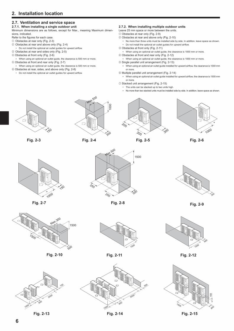
Fig 2-4
Fig 2- Fig 2-
Fig 2-10 Fig 2-11 Fig 2-12
Fig 2-1 Fig 2-14 Fig 2-15
Fig 2-
Fig 2-Fig 2-5Fig 2-
150
200
300200 1000
150
1000 300
15001500
500
1000600
2000
150
1500600
3000
500
1500800
150
Max.500
500
1000
Max.500
250
250
300
1500
Max.300
1500
500
1500
2 Insta ation o ation
2 Venti ation and ser i e s a e2 1 When insta ing a sing e outdoor unitMinimum dimensions are as follows, except for Max., meaning Maximum dimen-sions, indicated.Refer to the gures for each case.1 Obstacles at rear only (Fig. 2-3)2 Obstacles at rear and above only (Fig. 2-4)
Do not install the optional air outlet guides for upward air ow.3 Obstacles at rear and sides only (Fig. 2-5)4 Obstacles at front only (Fig. 2-6)
When using an optional air outlet guide, the clearance is 500 mm or more.5 Obstacles at front and rear only (Fig. 2-7)
When using an optional air outlet guide, the clearance is 500 mm or more.6 Obstacles at rear, sides, and above only (Fig. 2- )
Do not install the optional air outlet guides for upward air ow.
2 2 When insta ing u ti e outdoor unitsLeave 25 mm space or more between the units.1 Obstacles at rear only (Fig. 2-9)2 Obstacles at rear and above only (Fig. 2-10)
o more than three units must be installed side by side. In addition, leave space as shown. Do not install the optional air outlet guides for upward air ow.
3 Obstacles at front only (Fig. 2-11) When using an optional air outlet guide, the clearance is 1000 mm or more.
4 Obstacles at front and rear only (Fig. 2-12) When using an optional air outlet guide, the clearance is 1000 mm or more.
5 Single parallel unit arrangement (Fig. 2-13) When using an optional air outlet guide installed for upward air ow, the clearance is 1000 mm
or more.6 Multiple parallel unit arrangement (Fig. 2-14)
When using an optional air outlet guide installed for upward air ow, the clearance is 1500 mm or more.
7 Stacked unit arrangement (Fig. 2-15) The units can be stacked up to two units high. o more than two stacked units must be installed side by side. In addition, leave space as shown.

2 Wind o ation insta ationWhen installing the outdoor unit on a rooftop or other location unprotected from the wind, situate the air outlet of the unit so that it is not directly exposed to strong winds. Strong wind entering the air outlet may impede the normal air ow and a malfunction may result.The following shows two examples of precautions against strong winds.1 Install an optional air guide if the unit is installed in a location where strong winds
from a typhoon, etc. may directly enter the air outlet. (Fig. 2-16)A Air guide
2 Position the unit so that the air outlet blows perpendicularly to the seasonal wind direction, if possible. (Fig. 2-17)B Wind direction
Fig 2-1 Fig 2-1
2 Insta ation o ation
Insta ing the outdoor unit
(mm)
Be sure to install the unit in a sturdy, level surface to prevent rattling noises during operation. (Fig. 3-1)Foundation speci cations
Foundation bolt M10 (3 )Thickness of concrete 120 mmLength of bolt 70 mmWeight-bearing capacity 320 kg
Make sure that the length of the foundation bolt is within 30 mm of the bottom surface of the base.
Secure the base of the unit rmly with four-M10 foundation bolts in sturdy loca-tions.
Insta ing the outdoor unit Do not block the vent. If the vent is blocked, operation will be hindered and break-down may result.
In addition to the unit base, use the installation holes on the back of the unit to attach wires, etc., if necessary to install the unit. se self-tapping screws (ø5 15 mm or less) and install on site.
Warning: The unit ust e se ure insta ed on a stru ture that an sustain its weight I the unit is ounted on an unsta e stru ture, it a a down and ause da age or in uries
The unit ust e insta ed a ording to the instru tions in order to ini i e the ris o da age ro earth ua es, t hoons, or strong winds An in or-re t insta ed unit a a down and ause da age or in uries
Fig -1
A M10 (3 ) boltB BaseC As long as possible.D VentE Set deep in the ground.
4 Insta ing the re rigerant i ing
4 1 Pre autions or de i es that use R410A re rigerant Re er to age or re autions not in uded e ow on using air onditioners with R410A re rigerant
Use ester oi , ether oi , a en ene oi s a a ount as the re rigeration oi a ied to the ared se tions
Use C1220 o er hos horus, or o er and o er a o sea ess i es, to onne t the re rigerant i es Use re rigerant i es with the thi nesses s e i ed in the ta e to the e ow Ma e sure the insides o the i es are ean and do not ontain an har u onta inants su h as su uri o ounds, o idants, de ris, or dust Warning:
When insta ing or re o ating, or ser i ing the air onditioner, use on the s e i ed re rigerant R410A to harge the re rigerant ines Do not i it with an other re rigerant and do not a ow air to re ain in the inesI air is i ed with the re rigerant, then it an e the ause o a nor a high res-sure in the re rigerant ine, and a resu t in an e osion and other ha ardsThe use o an re rigerant other than that s e i ed or the s ste wi ause
e hani a ai ure or s ste a un tion or unit rea down In the worst ase, this ou d ead to a serious i edi ent to se uring rodu t sa et
ø6.35, ø9.52, ø12.7 Thickness 0. mmø15. Thickness 1.0 mm
Do not use i es thinner than those s e i ed a o e The thi nesses isted in the ta e a o e are ased on a anese standards Use i es with a a i u wor ing ressure o 4 15 MPa 01 PSI or higher a ording to o a standards
Max
.30
600 600Min.475
Min.251050
225 225 2537
033
0
B
A
D

B
A
H
B C
L
r
D e
a
h
b c d
C
C
B
A
A
A
a b c d
C
De f
H
h
L
r
C C C
C CC C C
A (mm)A Liquid pipe B Gas pipe
P MY-P112-140 ø9.52 ø15.
B, C, D (mm)C Total capacity of indoor units A Liquid pipe B Gas pipe
ø9.52 ø15.
a, b, c, d, e, f (mm)D Model number A Liquid pipe B Gas pipe
15, 20, 25, 32, 40, 50 ø6.35 ø12.763, 0, 100, 125, 140 ø9.52 ø15.
E Branch kit modelCMY-Y62-G-E
F 4-Branching header G -Branching headerCMY-Y64-G-E CMY-Y6 -G-E
* When connecting the CO ECTIO KIT (PAC-LV11M- ) and an M-series indoor unit, refer to the installation manual for the CO ECTIO KIT when selecting the pipe size and piping length.
4 Insta ing the re rigerant i ing
A Outdoor nitB First BranchC Indoor unitD Cap
A B C D a b c d e [ 300 mL A B C D e [ 150 m B C D e [ 30 m
H [ 50 m (Outdoor lower H [ 40 m)h [ 15 m
A a b c d e f [ 300 mL A f [ 150 m, f [ 30 mH [ 50 m (Outdoor lower H [ 40 m)h [ 15 m
Fig 4-14 2 2 Conne tion with Bran h Bo Fig 4-2F ared onne tions This unit has ared connections on each indoor unit and branch box and outdoor unit sides.
Remove the valve cover of the outdoor unit, then connect the pipe. Refrigerant pipes are used to connect the branch box and outdoor unit.
Fig 4-2
L
Ih2
b2b1
c1
a6a5a4a3a2
h3
h1H
a1a7 a8
A Outdoor unitB Branch boxC Indoor unit
Permissible length
(one-way)
Total piping length c1 b1 b2 a1 a2 a3 a4 a5 a6 a7 a [ 150 mFarthest piping length (L) c1 b2 a [ 0 m (b2 [ 55 m, a [ 25 m)Piping length between outdoor unit and branch boxes c1 b1 b2 [ 55 mFarthest branch box from the rst joint (b2) b2 [ 30 mFarthest piping length after branch box (l) a [ 25 mTotal piping length between branch boxes and indoor units a1 a2 a3 a4 a5 a6 a7 a [ 95 m
Permissible height differ-
ence(one-way)
In indoor outdoor section (H)*1H [ 50 m (In case of outdoor unit is set higher than indoor unit)H [ 40 m (In case of outdoor unit is set lower than indoor unit)
In branch box indoor unit section (h1) h1 h2 [ 15 mIn each branch unit (h2) h2 [ 15 mIn each indoor unit (h3) h3 [ 12 m
umber of bends c1 b1 a1 , c1 b1 a2 , c1 b1 a3 , c1 b1 a4 , c1 b1 a5 , c1 b2 a6 , c1 b2 a7 , c1 b2 a [ 15
*1 Branch box should be placed within the level between the outdoor unit and indoor units.
*1
4 2 Pi e ength and height di eren e4 2 1 Conne tion without Bran h Bo Fig 4-1
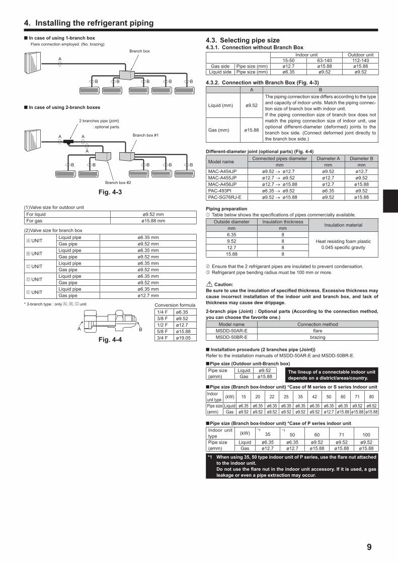
4 Se e ting i e si e4 1 Conne tion without Bran h Bo
Indoor unit Outdoor unit15-50 63-140 112-140
Gas side Pipe size (mm) ø12.7 ø15. ø15.Liquid side Pipe size (mm) ø6.35 ø9.52 ø9.52
4 2 Conne tion with Bran h Bo Fig 4-A B
Liquid (mm) ø9.52
The piping connection size differs according to the type and capacity of indoor units. Match the piping connec-tion size of branch box with indoor unit.If the piping connection size of branch box does not match the piping connection size of indoor unit, use optional different-diameter (deformed) joints to the branch box side. (Connect deformed joint directly to the branch box side.)
Gas (mm) ø15.
Di erent-dia eter oint o tiona arts Fig 4-4
Model nameConnected pipes diameter Diameter A Diameter B
mm mm mmMAC-A454 P ø9.52 ø12.7 ø9.52 ø12.7MAC-A455 P ø12.7 ø9.52 ø12.7 ø9.52MAC-A456 P ø12.7 ø15. ø12.7 ø15.PAC-493PI ø6.35 ø9.52 ø6.35 ø9.52PAC-SG76R -E ø9.52 ø15. ø9.52 ø15.
Pi ing re aration1 Table below shows the speci cations of pipes commercially available.
Outside diameter Insulation thicknessInsulation material
mm mm6.35
Heat resisting foam plastic0.045 speci c gravity
9.5212.715.
2 Ensure that the 2 refrigerant pipes are insulated to prevent condensation.3 Refrigerant pipe bending radius must be 100 mm or more.
Caution:Be sure to use the insu ation o s e i ed thi ness E essi e thi ness a
ause in orre t insta ation o the indoor unit and ran h o , and a o thi ness a ause dew dri age
2- ran h i e oint : O tiona arts A ording to the onne tion ethod, ou an hoose the a orite one
Model name Connection methodMSDD-50AR-E areMSDD-50BR-E brazing
■ Insta ation ro edure 2 ran hes i e ointRefer to the installation manuals of MSDD-50AR-E and MSDD-50BR-E.
■ Pi e si e Outdoor unit-Bran h oPipe size(ømm)
Liquid ø9.52Gas ø15.
■ Pi e si e Bran h o -Indoor unit Case o M series or S series Indoor unitIndoor unit type (kW) 15 20 22 25 35 42 50 60 71 0
Pipe size(ømm)
Liquid ø6.35 ø6.35 ø6.35 ø6.35 ø6.35 ø6.35 ø6.35 ø6.35 ø9.52 ø9.52Gas ø9.52 ø9.52 ø9.52 ø9.52 ø9.52 ø9.52 ø12.7 ø15. ø15. ø15.
■ Pi e si e Bran h o -Indoor unit Case o P series indoor unitIndoor unit type (kW)
*135
*150 60 71 100
Pipe size(ømm)
Liquid ø6.35 ø6.35 ø9.52 ø9.52 ø9.52Gas ø12.7 ø12.7 ø15. ø15. ø15.
1 When using 5, 50 t e indoor unit o P series, use the are nut atta hed to the indoor unit
Do not use the are nut in the indoor unit a essor I it is used, a gas ea age or e en a i e e tra tion a o ur
(1) Valve size for outdoor unitFor liquid ø9.52 mmFor gas ø15. mm
(2) Valve size for branch box
A ITLiquid pipe ø6.35 mmGas pipe ø9.52 mm
B ITLiquid pipe ø6.35 mmGas pipe ø9.52 mm
C ITLiquid pipe ø6.35 mmGas pipe ø9.52 mm
D ITLiquid pipe ø6.35 mmGas pipe ø9.52 mm
E ITLiquid pipe ø6.35 mmGas pipe ø12.7 mm
* 3-branch type : only A, B, C unit
BA
Fig 4-4
Fig 4-
A
B B B B B
Branch box
■ In ase o using 1- ran h oFlare connection employed. ( o. brazing)
■ In ase o using 2- ran h o es
Branch box #1
2 branches pipe (joint) : optional parts.
Branch box #2
Conversion formula1 4 F ø6.353 F ø9.521 2 F ø12.75 F ø15.3 4 F ø19.05
A A
A
B B B B B
4 Insta ing the re rigerant i ing
The ineu o a onne ta e indoor unit de ends on a distri t areas ountr

10
A Flare cutting dimensionsB Flare nut tightening torque
A DieB Copper pipe
Fig 4-5
A
Fig 4-
A (Fig. 4-5)
B (Fig. 4-5)
90°±
0.5
°
øA45°± 2°
R0.4 - R0.
Copper pipe O.D. (mm)
Flare dimensions øA dimensions (mm)
ø6.35 .7 - 9.1ø9.52 12. - 13.2ø12.7 16.2 - 16.6
ø15. 19.3 - 19.7
Copper pipe O.D. (mm)
Flare nut O.D. (mm)
Tightening torque ( m)
ø6.35 17 14 - 1ø6.35 22 34 - 42ø9.52 22 34 - 42ø12.7 26 49 - 61ø12.7 29 6 - 2ø15. 29 6 - 2ø15. 36 100 - 120
4 4 Conne ting i es Fig 4-5Fig. 4-1 is a sample of piping system. Conduct suf cient anti-condensation and insulation work to prevent water dripping from the refrigerant piping. (liquid pipe gas pipe)
Increase insulation depending on the environment where the refrigerant piping is installed, or condensation may occur on the surface of the insulation material. (In-sulation material Heat-resistant temperature: 120 °C, Thickness: 15 mm or more)* When the refrigerant piping is used in locations subject to high temperature and
humidity such as in the attic, further addition of insulation may be required. To insulate the refrigerant piping, apply heat-resistant polyethylene foam between the indoor unit and insulation material as well as to the net between the insulation material lling all gaps.
(Condensation forming on the piping may result in condensation in the room or burns when contacting the piping.)
The indoor parts of the drain pipe should be wrapped with polyethylene foam insula-tion materials (speci c gravity of 0.03, thickness of 9 mm or more).
Apply thin layer of refrigerant oil to pipe and joint seating surface before tightening are nut. A
se two wrenches to tighten piping connections. B se leak detector or soapy water to check for gas leaks after connections are completed.
Apply refrigerating machine oil over the entire are seat surface. C se the are nuts for the following pipe size. D When bending the pipes, be careful not to break them. Bend radius of 100 mm to 150 mm is suf cient.
Make sure the pipes do not contact the compressor. Abnormal noise or vibration may result.
1 Pipes must be connected starting from the indoor unit. Flare nuts must be tightened with a torque wrench.2 Flare the liquid pipes and gas pipes and apply a thin layer of refrigeration oil (Ap-
plied on site). When usual pipe sealing is used, refer to Table 3 for aring of R410A refrigerant pipes.
The size adjustment gauge can be used to con rm A measurements.
Warning:When insta ing the unit, se ure onne t the re rigerant i es e ore starting the o ressor
* To connect the CO ECTIO KIT (PAC-LV11M- ), refer to the installation manual for the CO ECTIO KIT.
Table 3 (Fig. 4-6)
Copper pipe O.D. (mm)A (mm)
Flare tool for R410A Flare tool for R22 R407CClutch type
ø6.35 0 - 0.5 1.0 - 1.5ø9.52 0 - 0.5 1.0 - 1.5ø12.7 0 - 0.5 1.0 - 1.5
ø15. 0 - 0.5 1.0 - 1.5ø19.05 0 - 0.5 1.0 - 1.5
4 Insta ing the re rigerant i ing
4 5 Re rigerant i ing Fig 4-Remove the service panel D (three screws) and the front piping cover A (two screws) and rear piping cover B (two screws).1 Perform refrigerant piping connections for the indoor outdoor unit when the outdoor
unit’s stop valve is completely closed.2 Vacuum-purge air from the indoor unit and the connection piping.3 After connecting the refrigerant pipes, check the connected pipes and the indoor
unit for gas leaks. (Refer to 4.6. Refrigerant pipe airtight testing method)4 Vacuumize the refrigerant lines through the service port of the liquid and gas stop
valves. And then open the stop valves completely (for both the liquid and gas stop valves). This will completely connect the refrigerant lines of the indoor and outdoor units.
If the stop valves are left closed and the unit is operated, the compressor and control valves will be damaged.
se a leak detector or soapy water to check for gas leaks at the pipe connec-tion sections of the outdoor unit.
Do not use the refrigerant from the unit to purge air from the refrigerant lines.
After the valve work is completed, tighten the valve caps to the correct torque: 20 to 25 m (200 to 250 kgf cm).
Failure to replace and tighten the caps may result in refrigerant leakage. In addition, do not damage the insides of the valve caps as they act as a seal to prevent refrigerant leakage.
5 se sealant to seal the ends of the thermal insulation around the pipe connection sections to prevent water from entering the thermal insulation.
A Front piping coverB Piping coverC Stop valveD Service panelE Bend radius : 100 mm - 150 mm
B
C
EA
D
Fig 4-

11
* The gure to the left is an example only. The stop valve shape, service port position, etc., may vary according to the model.
* Turn section A only. (Do not further tighten sections A and
B together.)
C Charge hoseD Service port
Pre autions when using the harge a e Fig 4-11Do not tighten the service port too much when installing it, otherwise, the valve core could be deformed and become loose, causing a gas leak.After positioning section B in the desired direction, turn section A only and tighten it.Do not further tighten sections A and B together after tightening section A.
Fig 4-11
4 Insta ing the re rigerant i ing
4 Re rigerant i e airtight testing ethod(1) Connect the testing tools.
Make sure the stop valves A B are closed and do not open them. Add pressure to the refrigerant lines through the service port C of the liquid
stop valve A and the gas stop valve B.(2) Do not add pressure to the speci ed pressure all at once add pressure little by lit-
tle.1 Pressurize to 0.5 MPa (5 kgf cm2G), wait ve minutes, and make sure the
pressure does not decrease.2 Pressurize to 1.5 MPa (15 kgf cm2G), wait ve minutes, and make sure the
pressure does not decrease.3 Pressurize to 4.15 MPa (41.5 kgf cm2G) and measure the surrounding tem-
perature and refrigerant pressure.(3) If the speci ed pressure holds for about one day and does not decrease, the pipes
have passed the test and there are no leaks. If the surrounding temperature changes by 1°C, the pressure will change by
about 0.01 MPa (0.1 kgf cm2G). Make the necessary corrections.(4) If the pressure decreases in steps (2) or (3), there is a gas leak. Look for the source
of the gas leak.
4 Sto a e o ening ethod(1) Gas side (Fig. 4-9)1 Remove the cap, pull the handle toward you and rotate 1 4 turn in a counterclock-
wise direction to open.2 Make sure that the stop valve is open completely, push in the handle and rotate
the cap back to its original position.(2) Liquid side (Fig. 4-10)1 Remove the cap and turn the valve rod counterclockwise as far as it will go with
the use of a 4 mm hexagonal wrench. Stop turning when it hits the stopper. (ø6.35: Approximately 4.5 revolutions) (ø9.52: Approximately 10 revolutions)2 Make sure that the stop valve is open completely, push in the handle and rotate
the cap back to its original position.A ValveB nit sideC HandleD CapE Local pipe side
A Stop valve Liquid sideB Stop valve Gas sideC Service portD Open Close sectionE Local pipe
F Open position sideG Service portH Wrench holeI Refrigerant ow direction
Refrigerant pipes are protectively wrapped The pipes can be protectively wrapped up to a diameter of ø90 before or after con-necting the pipes. Cut out the knockout in the pipe cover following the groove and wrap the pipes.
Pipe inlet gap se putty or sealant to seal the pipe inlet around the pipes so that no gaps re-main.
(If the gaps are not closed, noise may be emitted or water and dust will enter the unit and breakdown may result.)
Fig 4-(1) 1 2
Fig 4-10
Fig 4-
(2) 1 2
F Sealed, same way for gas sideG Pipe coverH Do not use a wrench here. Refrigerant leakage may result.I se two wrenches here.

12
4 Insta ing the re rigerant i ing
5 Drainage i ing worOutdoor unit drainage i e onne tionWhen drain piping is necessary, use the drain socket or the drain pan (option).
P112-140Drain socket PAC-SG61DS-EDrain pan PAC-SH97DP-E
1 Caution1 Follow ordinance of your governmental organization for technical standard related
to electrical equipment, wiring regulations and guidance of each electric power company.
2 Wiring for control (hereinafter referred to as transmission line) shall be (5 cm or more) apart from power source wiring so that it is not in uenced by electric noise from power source wiring. (Do not insert transmission line and power source wire in the same conduit.)
3 Be sure to provide designated grounding work to outdoor unit.4 Give some allowance to wiring for electrical part box of indoor and outdoor units,
because the box is sometimes removed at the time of service work.5 ever connect the main power source to terminal block of transmission line. If
connected, electrical parts will be burnt out.6 se 2-core shield cable for transmission line. If transmission lines of different
systems are wired with the same multiplecore cable, the resultant poor transmit-ting and receiving will cause erroneous operations.
7 Only the transmission line speci ed should be connected to the terminal block for outdoor unit transmission.
(Transmission line to be connected with indoor unit : Terminal block TB3 for transmission line, Other : Terminal block TB7 for centralized control)
Erroneous connection does not allow the system to operate.
E e tri a wor
8 In case to connect with the upper class controller or to conduct group operation in different refrigerant systems, the control line for transmission is required between the outdoor units each other.
Connect this control line between the terminal blocks for centralized control. (2-wire line with no polarity)
When conducting group operation in different refrigerant systems without connect-ing to the upper class controller, replace the insertion of the short circuit connector from C 41 of one outdoor unit to C 40.
9 Group is set by operating the remote controller.0 When connecting the CO ECTIO KIT (PAC-LV11M- ) and an M-series indoor
unit, refer to the installation manual for the CO ECTIO KIT. 1 When connecting a branch box, be sure to turn on the indoor units and the branch
box before turning on the outdoor unit.
4 Additiona re rigerant hargeAdditiona re rigerant hargeRefrigerant for the extended piping is not included in the outdoor unit when the unit is shipped from the factory. Therefore, charge each refrigerant piping system with addi-tional refrigerant at the installation site. In addition, in order to carry out service, enter the size and length of each liquid pipe and additional refrigerant charge amounts in the spaces provided on the “Refrigerant amount” plate on the outdoor unit.Ca u ation o additiona re rigerant harge Calculate the additional charge using the liquid pipe size and length of the ex-tended piping and total capacity of connected indoor units.
In the calculation, use 11.2 kW for the capacity of the Cylinder or Hydrobox unit. Calculate the additional refrigerant charge using the procedure shown to the right, and charge with the additional refrigerant.
For amounts less than 0.1 kg, round up the calculated additional refrigerant charge.
(For example, if the calculated charge is 6.01 kg, round up the charge to 6.1 kg.)
ExampleOutdoor model : P125Indoor 1 : P63 (7.1 kW) A : ø9.52 30 m a : ø9.52 15 m 2 : P40 (4.5 kW) b : ø6.35 10 m 3 : P25 (2. kW) c : ø6.35 10 m 4 : P20 (2.2 kW) d : ø6.35 20 mThe total length of each liquid line is as follows:ø9.52 : A a 30 15 45 mø6.35 : b c d 10 10 20 40 mThe total capacity of connected indoor unit is as follows:7.1 4.5 2. 2.2 16.6
Calculation exampleAdditional refrigerant charge
At the conditions below:
40 ×19.0 45 × 50.0 3.0 6.1 kg (rounded up)1000 1000
Additional Charge
Ca u ation o re rigerant hargePipe sizeLiquid pipe
Pipe sizeLiquid pipe
Total capacity of connected indoor units
Amount for the indoor units
ø6.35 ø9.52 .0 kW 1.5 kg
(m) 19.0 (g m) (m) 50.0 (g m) .1 16.0 kW 2.5 kg
16.1 kW ~ 3.0 kg
In uded re rigerant a ount when shi ed ro the a torIncluded refrigerant amount
4. kg

1
Wiring trans ission a es1 T es o ontro a es1. Wiring transmission cables Types of transmission cables: Shielding wire CVVS, CPEVS or MVVS Cable diameter: More than 1.25 mm2 Maximum wiring length: Within 200 m
2. M- ET Remote control cablesKind of remote control cable Shielding wire CVVS, CPEVS or MVVS
Cable diameter 0.5 to 1.25 mm2
Remarks When 10 m is exceeded, use cable with the same speci cations as transmission line wiring cables.
E a e o a grou o eration s ste with u ti e outdoor units Shie ding wires and address setting are ne essarExamples of Transmission Cable Wiring: When ot sing a Branch Box
■ M-NET Re ote Contro er Fig -2■ MA Re ote Contro er Fig -
Wiring Method and Address Settingsa. Always use shielded wire when making connections between the outdoor unit (OC) and the indoor unit (IC), as well for all OC-OC, and IC-IC wiring intervals.b. se feed wiring to connect terminals M1 and M2 and the ground terminal on the transmission cable terminal block (TB3) of each outdoor unit (OC) to terminals M1, M2
and terminal S on the transmission cable terminal block of the indoor unit (IC).c. Connect terminals 1 (M1) and 2 (M2) on the transmission cable terminal block of the indoor unit (IC) that has the most recent address within the same group to the terminal
block on the remote controller (RC).d. Connect together terminals M1, M2 and terminal S on the terminal block for centralized control (TB7) for the outdoor unit (OC).e. The jumper connector C 41 on the control panel does not change.f. Connect shield ground of the indoor units transmission line to the shield (S) terminal of (TB3) and also connect (S) terminal to the screw (E or F) using attached lead
wire. Connect shield ground of the line between outdoor units and the centralized control system transmission line to the shield (S) terminal of (TB7). g. Set the address setting switch as follows.
nit Range Setting MethodIC (Main) 01 to 50 se the most recent address within the same group of indoor units
IC (Sub) 01 to 50 se an address, other than that of the IC (Main) from among the units within the same group of indoor units. This must be in sequence with the IC (Main)
Outdoor nit 51 to 100 se the most recent address of all the indoor units plus 50* The address automatically becomes “100” if it is set as “01 - 50”.
M- ET R C (Main) 101 to 150 Set at an IC (Main) address within the same group plus 100M- ET R C (Sub) 151 to 200 Set at an IC (Main) address within the same group plus 150
MA R C – nnecessary address setting ( ecessary main sub setting)
h. The group setting operations among the multiple indoor units is done by the remote controller (RC) after the electrical power has been turned on.i. When connecting a PWFY unit Do not perform the group settings for the PWFY unit and the indoor units. The PWFY unit and a Lossnay unit cannot be set to operate at the same time. se a WMA remote controller for the PWFY unit.
For details, refer to the installation manual for the PWFY unit.j. When connecting a Cylinder or Hydrobox unit Do not perform the group settings for the Cylinder or Hydrobox unit and the other indoor units.
E e tri a wor
M1 SM2
DA
EM1 SM2L N
TB3TB1 TB7
FB1 B2
TB1B
CB
A Power sourceB Power supply for branch boxC Screw on the electrical component boxD Transmission line
2 Contro o and onne ting osition o wiring Fig -11. Connect the indoor unit transmission line to transmission terminal block (TB3), or
connect the wiring between outdoor units or the wiring with the centralized control system to the centralized control terminal block (TB7).
When using shielded wiring, connect shield ground of the indoor unit transmission line to the screw (E or F) and connect shield ground of the line between outdoor units and the centralized control system transmission line to the shield (S) terminal of the centralized control terminal block (TB7) shield (S) terminal. In addition, in the case of outdoor units whose power supply connector C 41 has been replaced by C 40, the shield terminal (S) of terminal block (TB7) of the centralized control system should also be connected to the screw (E or F) using attached lead wire.
2. The terminal bed (TB1B) is for supplying power to the branch box (220 ~ 240 VAC. max 6 A).
Caution:Ne er onne t the trans ission ine or the indoor unit or the entra i ed ontro s ste trans ission ine to this ter ina ed TB1B I the trans ission ines are onne ted, the indoor unit ter ina o or entra i ed ontro ter ina
o ou d e da aged
Fig -1
PUMY-P VKM
M1 SM2 M1 SM2
TB3 TB7
B1 B2
TB1B
CB
E
F
D
L1 L2 L3 N
TB1
A
PUMY-P YKM
E Screw on the electrical component boxF Screw on the electrical component box
3. MA Remote control cablesKind of remote control cable Sheathed 2-core cable (unshielded) CVV
Cable diameter 0.3 to 1.25 mm2 (0.75 to 1.25 mm2)*Remarks Within 200 m
* Connected with simple remote controller.2 Wiring e a es Controller name, symbol and allowable number of controllers.
ame Symbol Allowable number of controllersOutdoor unit controller OC –
Indoor unit controller ICP MY-P112 1 to 10 units per 1 OCP MY-P125 1 to 12 units per 1 OCP MY-P140 1 to 12 units per 1 OC
Remote controller RCRC
(M- ET)Maximum of 12 controllers for 1 OC
MA Maximum of 2 per group

14
E e tri a wor
■ MA Re ote Contro er
Fig -2 Fig -
A : GroupB : GroupC : GroupD : Shielded WireE : Sub Remote ControllerF : Screw on the electrical component box( ): Address
■ M-NET Re ote Contro er
A
B
C
E
D
TB7TB3
IC(51)
TB5
RC
(01)
IC
TB5
(03)
IC
TB5
(02)
IC
TB5
(04)
IC
TB5
(05)
IC
TB5
(07)
IC
TB5
(06)
L2
L1
(101)RC(105)
RC(104)
RC(155)
OC
TB7
(53)
OC
3
L3
L6
L7
L4
L5
2
4
1
F
r
rr r
M1M2 S M1M2 S M1M2 S M1M2 S
A BA BA B
M1M2 S M1M2 S M1M2 SSM1M2 STB3
M1M2 S
M1M2 S
A B
M1M2
M1M2 S M1M2 S
F
TB7
SM1M2
NO
NO
A
B
C
E
D
TB7
IC(51)
TB15 TB15
TB15
MA
(01)
IC
TB5
(03)
IC
TB5TB5
(02)
IC
TB5
(04)
IC(05)
IC(07)
IC(06)
L1
MA
MA
MA
OC
(53)OC
1
m4
3
L3
L7
L4
m3
1
1
2 2
TB3
m
m
m
m
mm
M1M2 S M1M2 S
TB7
M1M2 SM1M2 S
TB3
M1M2 S
M1M2 S
M1M2 S M1M2 S
M1M2 S
A B
1 2
1 2 M1M2 S 1 2
1 2TB15TB5
M1M2 S 1 2TB15TB5
M1M2 S 1 2
A B A B
TB15 TB5M1M2 S 1 2
TB15
A B
L2
L6
F
F
TB7
SM1M2
NO
NO
C or D
C or D
C or D
C or D
A : GroupB : GroupC : GroupD : Shielded WireE : Sub Remote ControllerF : Screw on the electrical component box( ): Address
Permissible Lengths1 M-NET Re ote ontro er Max length via outdoor units: L1 L2 L3 L4 and L1 L2 L3 L5 and L1 L2 L6 L7 [ 500 m (1.25 mm2 or more) Max transmission cable length: L1 and L3 L4 and L3 L5 and L6 and L2 L6 and L7 [ 200 m (1.25 mm2 or more) Remote controller cable length: 1, 2, 2 3, 4 [ 10 m (0.5 to 1.25 mm2)
If the length exceeds 10 m, use a 1.25 mm2 shielded wire. The length of this section (L ) should be included in the calculation of the maxi-mum length and overall length.
2 MA Re ote ontro er Max length via outdoor unit (M- ET cable): L1 L2 L3 L4 and L1 L2 L6 L7 [ 500 m (1.25 mm2 or more) Max transmission cable length (M- ET cable): L1 and L3 L4 and L6 and L2 L6 and L7 [ 200 m (1.25 mm2 or more) Remote controller cable length: m1 and m1 m2 m3 and m1 m2 m3 m4 [ 200 m (0.3 to 1.25 mm2)
Power Supply nit
System controller
Power Supply nit
System controller
Fig -4
Per issi e LengthsMa ength ia outdoor units M-NET a e : L1 L2 L L4 L5 500 1 25 2 or oreMa trans ission a e ength M-NET a e : L1 L2, L , L L4, L5 200 1 25 2 or ore
G : Shielded wire( ) : Address example
Example of Transmission Cable Wiring: When sing a Branch Box
TB7TB3
(51)
L3
L1
OC
TB7
(53)
OC
DC24V
L4
L5
M1 M2 S M1 M2 S
SM1 M2 STB3
M1 M2 S
M1 M2 S
M1 M2
TB3A
IC(01)
IC(02)
IC(03)
IC(04)
IC
MA
MA
MA
MA
RC
RC
RC
RC
(05)
IC(06)
IC(07)
IC(08)
S1S2S3
TB3AS1S2
TB1512
AB
AB
AB
AB
TB1512
TB1512
TB1512
S3
TB3AS1S2S3
TB3AS1S2S3
TB3AS1S2S3
TB3AS1S2S3
TB3AS1S2S3
TB3AS1S2S3
TB3AS1S2S3
TB3BS1S2S3
TB3CS1S2S3
TB3DS1S2S3
TB3ES1S2S3
TB3AS1S2S3
TB3BS1S2S3
TB3CS1S2S3
M1M2S
TB5
M1M2S
TB5
L
(01)
(06)
2
A
A
G
Power Supply nit
System controller
Branch Box
Branch Box

15
E e tri a wor
4 Wiring o ain ower su and e ui ent a a itS he ati Drawing o Wiring: When Not Using a Bran h Bo E a e Fig -5
PUMY-P VKM series
A Switch (Breakers for Wiring and Current Leakage)B Outdoor nit C Pull Box D A-Control Indoor nit (M.P.S series indoor unit)E M- ET Control Indoor nit (City Multi indoor unit)Fig -5
A B
E E
C
A
E E
PUMY-P YKM E series
~ 220 230 240 V 50 Hz~ 220 V 60 Hz
3 ~380 400 415 V 50 Hz
~ 220 230 240 V 50 Hz~ 220 V 60 Hz
A Switch (Breakers for Wiring and Current Leakage)
B Outdoor nit
C Branch Box
D A-Control Indoor nit (M.P.S series indoor unit)
E M- ET Control Indoor nit (City Multi indoor unit)
F Pull Box
Fig -
B1/B2S1/S2/S3
S1/S2/S3
S1/S2/S3
L/N
L/N
S1/S2/S3
S1/S2/S3
S1/S2/S3
L/N
L/NA
B
When Power Is Supplied Separately
~ 220 230 240 V 50 Hz~ 220 V 60 Hz
When Power Is Supplied from the Outdoor nit
PUMY-P VKM series
PUMY-P VKM series
~ 220 230 240 V 50 Hz~ 220 V 60 Hz
L1/L2/L3/N
PUMY-P YKM E series
3 ~380 400 415 V 50 Hz
~ 220 230 240 V 50 Hz~ 230 V 60 Hz
B1/B2S1/S2/S3
S1/S2/S3
S1/S2/S3
L/N
L/N
S1/S2/S3
S1/S2/S3
S1/S2/S3
L1/L2/L3/N3 ~380 400 415 V 50 Hz
PUMY-P YKM E series
S he ati Drawing o Wiring: When using a Bran h Bo E a e Fig -
Note: Rea tor BO O tiona artsWhen the rodu t is used or a ur ose other than as ro essiona e ui ent, the Rea tor BO a e ne essar
L/N
S1/S2/S3
S1/S2/S3
S1/S2/S3
L/N
S1/S2/S3
S1/S2/S3
S1/S2/S3
D
C
D
D
D
C
D
AF
Grounded
Branch box power supply method
Outdoor unit Power supply from outdoor unit Separate power supply
1-phase power supply nnecessary ecessary3-phase power supply ecessary ecessary

1
E e tri a wor
Connect to Branch box (PAC-MK BC)Indoor unit V1 V2Type 1 SEZ-KD VA, PCA-RP KA , PLA-ZRP BA(. K) 19.8
2.4
Type 2 PEAD-RP A (L). K 26.9Type 3 MLZ-KA VA, SLZ-KA, VA (L)3 9.9
Type 4 MSZ-FH VE, MSZ-SF VE, MSZ-EF VE, MSZ-SF VA, MSZ-GF VE 6.8
Type 5 MFZ-K VE 7.4Type 6 Branch box (PAC-MK BC) 5.1 3.0Type 7 ecodan C generation 5.1 5.0*
* This value may increase due to a locally connected actuator.
Connect to Connection kit (PAC-LV11M)Indoor unit V1 V2
Type 1 MSY-EF VE, MSY-GE VA, MSY-GH, MSZ-GE VA,MSZ-SF VA, MSZ-SF VE, MSZ-EF VE, MSZ-FH VE 6.8
2.4Type 2 MFZ-K VE 7.4Type 3 Connection kit (PAC-LV11M) 3.5
Indoor unit V1 V2
Type 1 PMFY-VBM, PLFY-VBM, PEFY-VMS1, PCFY-VKM, PKFY-VHM, PKFY-VKM, PFFY-VKM, PFFY-VLRMM 19.8
2.4Type 2 PLFY-VCM 9.9Type 3 PKFY-VBM 3.5Type 4 PEFY-VMA 38 1.6
Type 5 PLFY-VLMD, PEFY-VMH, PEFY-VMR, PDFY-VM,PFFY-VLEM, PFFY-VLRM, PWFY-VM 0 0
C : Multiple of tripping current at tripping time 0.01sPlease pick up “C” from the tripping characteristic of the breaker.
Cross-se tiona area o Wire or Main Power Su and On O Ca a itiesWhen power is supplied separately
ModelPower Supply
Minimum Wire Cross-sectional area (mm2)Breaker for Wiring *1 Breaker for Current Leakage
Main Cable Branch Ground
Outdoor nit P112-140V ~ 220 230 240 V 50 Hz
~ 220 V 60 Hz 6 – 6 32 A 32 A 30 mA 0.1 sec. or less
P112-140Y 3 ~380 400 415 V 50 Hz 1.5 – 1.5 16 A 16 A 30 mA 0.1 sec. or less
When power is supplied from the outdoor unit
ModelPower Supply
Minimum Wire Cross-sectional area (mm2)Breaker for Wiring *1 Breaker for Current Leakage
Main Cable Branch Ground
Outdoor nit P112-140V ~ 220 230 240 V 50 Hz
~ 220 V 60 Hz 6 – 6 40 A 40 A 30 mA 0.1 sec. or less
P112-140Y 3 ~380 400 415 V 50 Hz 2.5 – 2.5 20 A 20 A 30 mA 0.1 sec. or less*1 A breaker with at least 3.0 mm contact separation in each poles shall be provided. se non-fuse breaker ( F) or earth leakage breaker ( V).
Indoor units
Total operating current of the indoor unitMinimum wire thickness (mm2)
Ground-fault interruper *1Local switch (A) Breaker for wiring
( FB)Main Cable Branch Ground Capacity FuseF0 = 16 A or less *2 1.5 1.5 1.5 20 A current sensitivity *3 16 16 20F0 = 25 A or less *2 2.5 2.5 2.5 30 A current sensitivity *3 25 25 30F0 = 32 A or less *2 4.0 4.0 4.0 40 A current sensitivity *3 32 32 40
Apply to IEC61000-3-3 about max. permissive system impedance.*1 The Ground-fault interrupter should support inverter circuit. The Ground-fault interrupter should combine using of local switch or wiring breaker.*2 Please take the larger of F1 or F2 as the value for F0.F1 = Total operating maximum current of the indoor units × 1.2F2 = V1 × ( uantity of Type1) C V1 × ( uantity of Type2) C V1 × ( uantity of Type3) C V1 × ( uantity of Others) C

1
1 Bear in ind a ient onditions a ient te erature, dire t sun ight, rain water, et when ro eeding with the wiring and onne tions2 The wire si e is the ini u a ue or eta onduit wiring The ower ord si e shou d e 1 ran thi er onsideration o o tage dro s Ma e sure the ower-su o tage does not dro ore than 10
S e i wiring re uire ents shou d adhere to the wiring regu ations o the region4 Power su ords o arts o a ian es or outdoor use sha not e ighter than o h oro rene sheathed e i e ord design 0245 IEC5 For e a e,
use wiring su h as YZW5 Insta an earth onger than other a es
Sample chart
E e tri a wor
Warning: In ase o A- ontro wiring, there is high o tage otentia on the S ter ina aused e e tri a ir uit design that has no e e tri a insu ation etween
ower ine and o uni ation signa ine There ore, ease turn o the ain ower su when ser i ing And do not tou h the S1, S2, S ter ina s when the ower is energi ed I iso ator shou d e used etween outdoor unit and ran h o indoor unit and ran h o , ease use - o e t e or 2- o e t e P ease re er to gure e ow
Caution:A ter using the iso ator, e sure to turn o and on the ain ower su to reset the s ste Otherwise, the outdoor unit a not e a e to dete t the ran h
o es or indoor units
Be sure to connect the outdoor-branch box indoor-branch box connecting cables directly to the units (no intermediate connections).Intermediate connections can lead to communication errors if water enters the cables and causes insuf cient insulation to ground or a poor electrical contact at the intermediate connection point.(If an intermediate connection is necessary, be sure to take measures to prevent water from entering the cables.)
B1
B2
L
NOutdoor unit
2 poles isolator (Switch)
Branch box
Warning: Be sure to use s e i ed wires to onne t so that no e terna or e is i arted to ter ina onne tions I onne tions are not ed r , it a ause heat-
ing or re Be sure to use the a ro riate t e o o er urrent rote tion swit h Note that generated o er urrent a in ude so e a ount o dire t urrent Be sure to atta h the ter ina o o ers ane o the outdoor unit se ure
I it is not atta hed orre t , i ou d resu t in a re or an e e tri sho due to dust, water et
Caution: Be are u not to a e is-wiring Fir tighten the ter ina s rews to re ent the ro oosening A ter tightening, u the wires ight to on r that the not o e I the onne ting wire is in orre t onne ted to the ter ina o , the unit does not o erate nor a So e insta ation site a re uire atta h ent o an earth ea age rea er I no earth ea age rea er is insta ed, it a
ause an e e tri sho Do not use an thing other than rea er and use with orre t a a it Using use and wire or o er wire with too arge
a a it a ause a a un tion o unit or re
IMPORTANTMa e sure that the urrent ea age rea er is one o ati e with higher har oni sA wa s use a urrent ea age rea er that is o ati e with higher har oni s as this unit is e ui ed with an in erterThe use o an inade uate rea er an ause the in orre t o eration o in erter
ever splice the power cable or the indoor-outdoor-branch box connection cable, otherwise it may result in a smoke, a re or communication failure.
Example of “F2” calculationCondition PEFY-VMS × 4 PEFY-VMA × 1, C = 8 (refer to right sample chart)F2 = 18.6 × 4 8 38 × 1 8 = 14.05 16 A breaker (Tripping current = 8 × 16 A at 0.01 s)* 3 Current sensitivity is calculated using the following formula.G1 = V2 × ( uantity of Type1) V2 × ( uantity of Type2) V2 × ( uantity of Type3) V2 × ( uantity of Others) V3 × (Wire length km )
G1 Current sensitivity30 or less 30 mA 0.1 sec or less100 or less 100 mA 0.1 sec or less
Wire thickness V31.5 mm2 482.5 mm2 564.0 mm2 66
6000
600
60
10
1
1 2 3 4 6 8
C
10 20
Rated Tripping current (x)
SAMPLE
0.1
0.01
Trip
ping
Tim
e s
Connection details
Lead wireTerminal block
Loosen terminal screw.

1
E e tri a wor
5 Address settingSwitch address setting
nitAddress
OutdoorBranch Box
IndoorAddress Connection Setting
Switch
Port A B C D E –
O
OFF 1 2 3 4 5 6*
O : Indoor connectOFF: o connection one
tens digit
ones digit
tens digit
ones digit
SW 2 SW 1 SW12 SW11 SW1 *SW1-6 not userange 51 - 100 1 - 50 – –
setting Branch address 50
According to the set address (for example, 01), the addresses for the connected indoor units are set sequentially (for example, 02, 03, 04, and 05).
Specify whether indoor units are connected to each port (A, B, C, D, and E).
There are no address settings for the indoor units.
SW1 1 2 3 4 5
O O O O O
Port A B C D E
Address 01 (SW11, 12)
02 03 04 05 (sequential numbers)
SW1 1 2 3 4 5 (6)
Port A B C D E (not use) Indoor units are connected O Indoor units are not connected OFF
Note: 1 Bran h o address When setting the address, use a nu er within the range 1 50 E The set address is 4 and there are 5 indoor units A, B, C, D, and E I A: 4 , B: 4 , C: 4 , D: 50 , and E: 51 , E is in orre t e ause it e eeds 50Ex1. Outdoor Branch 1 (Indoor A, B, C, D, E) Branch 2 (Indoor A, B, C)
Outdoor
address(51) *1
*1 Outdoor address Branch-Box 1 start address 50 = 01 50 = 51*2 Branch-Box 1 A-port address = Start address = 01 B-port address = Start address 1 = 02 C-port address = Start address 2 = 03 D-port address = Start address 3 = 04 E-port address = Start address 4 = 05
*3 Branch-Box 2 Branch-Box 2 start address = Branch-Box 1 oldest start address 1 = 05 1 = 06 A-port address = Start address = 06 B-port address = Start address 1 = 07 C-port address = Start address 2 = 08
Ex2. Outdoor Branch 1 (Indoor A, C, E) Branch 2 (Indoor A, C, E)
Outdoor
address(51) *1
*1 Outdoor address Branch-Box 1 start address 50 = 01 50 = 51*2 Branch-Box 1 A-port address = Start address = 01 B-port address no connection C-port address = Start address 1 = 02 D-port address no connection E-port address = Start address 2 = 03
*3 Branch-Box 2 Branch-Box 2 start address = Branch-Box 1 oldest start address 1 = 03 1 = 04 A-port address = Start address = 04 B-port address no connection C-port address = Start address 1 = 05 D-port address no connection E-port address = Start address 2 = 06
Indoor Indoor Indoor Indoor Indoor
Indoor Indoor Indoor
Indoor
Indoor
Indoor
Indoor
Indoor
Indoor
(01) = A-port(02) = B-port(03) = C-port(04) = D-port(05) = E-port
(06) = A-port(07) = B-port(08) = C-port
(01) = A-portnon B-port(02) = C-portnon D-port(03) = E-port
(04) = A-portnon B-port(05) = C-portnon D-port(06) = E-port
Branch-Box 1address (01) *2
SW1 1, 3, 5 OSW1 2, 4 OFF
Branch-Box 2address (04) *3
SW1 1, 3, 5 OSW1 2, 4 OFF
Branch-Box 2address (06) *3
SW1 1, 2, 3 OSW1 4, 5 OFF
Branch-Box 1address (01) *2
SW1 1, 2, 3, 4, 5 O

1
2 Test run2 1 Using re ote ontro er
Refer to the indoor unit installation manual.
Be sure to perform the test run for each indoor unit. Make sure each indoor unit operates properly following the installation manual attached to the unit.
If you perform the test run for all indoor units at once, you cannot detect any erroneous connection, if any, of the refrigerant pipes and the connecting wires.
* The compressor operation is not available for 3 minutes at least after the power is supplied.
The compressor can emit noise just after turn on the power supply or in case of low outside air temperature.
Re rigerant o e ting Pu downPerform the following procedures to collect the refrigerant when moving the indoor unit or the outdoor unit.1 Turn off the circuit breaker.2 Connect the low pressure side of the gauge manifold to the service port of the
gas side stop valve.3 Close the liquid stop valve.4 Supply power (circuit breaker).
* Start-up of the indoor-outdoor communication takes about 3 minutes after the power (circuit breaker) is turned on. Start the pump-down operation 3 to 4 minutes after the power (circuit breaker) is turned O .
5 Perform the test run for cooling operation. (Con rm that SW3-2 is set to OFF, and then set SW3-1 to O .) The compressor (outdoor unit) and ventilators (indoor and outdoor units) start operating and test run for cooling operation begins. After the cooling operation has been carried out for approximately ve minutes, set the outdoor service switch SW2-4 (pump down switch) from OFF to O .
* Do not continue to operate for a long time with the switch SW2-4 set to O . Make sure to switch it to OFF after pump down is completed.
6 Fully close the gas stop valve when the pressure reading on the gauge drops 0.05 - 0.00 MPa (approximately 0.5 - 0.0 kgf cm2)
7 Stop the air conditioner operation (SW3-1: OFF and SW3-2: OFF). Set the outdoor service switch SW2-4 from O to OFF.
8 Turn off the power supply (circuit breaker). * If too much refrigerant has been added to the air conditioner system, the pressure
may not drop to 0.5 kgf cm2. If this occurs, use a refrigerant collecting device to collect all of the refrigerant in the system, and then recharge the system with the correct amount of refrigerant after the indoor and outdoor units have been relocated.
Warning:When u ing down the re rigerant, sto the o ressor e ore dis onne t-ing the re rigerant i es The o ressor a urst and ause in ur i an oreign su stan e, su h as air, enters the s ste
1 Be ore test run A ter o eting insta ation and the wiring and i ing o the indoor and outdoor units, he or re rigerant ea age, ooseness in the ower su or ontro wiring, wrong o arit , and no dis onne tion o one hase in the su
Use a 500- o t M-oh tester to he that the resistan e etween the ower su ter ina s and ground is at east 1 M
Do not arr out this test on the ontro wiring ow o tage ir uit ter ina s Warning:
Do not use the air onditioner i the insu ation resistan e is ess than 1 M
Insu ation resistan eAfter installation or after the power source to the unit has been cut for an extended period, the insulation resistance will drop below 1 M due to refrigerant accumulat-ing in the compressor. This is not a malfunction. Perform the following procedures.1. Remove the wires from the compressor and measure the insulation resistance of
the compressor.2. If the insulation resistance is below 1 M , the compressor is faulty or the resist-
ance dropped due the accumulation of refrigerant in the compressor.
3. After connecting the wires to the compressor, the compressor will start to warm up after power is supplied. After supplying power for the times indicated below, measure the insulation resistance again.
The insulation resistance drops due to accumulation of refrigerant in the com-pressor. The resistance will rise above 1 M after the compressor is warmed up for 12 hours.
(The time necessary to warm up the compressor varies according to atmospheric conditions and refrigerant accumulation.)
To operate the compressor with refrigerant accumulated in the compressor, the compressor must be warmed up at least 12 hours to prevent breakdown.
4. If the insulation resistance rises above 1 M , the compressor is not faulty.
Caution: The o ressor wi not o erate un ess the ower su hase onne tion is orre t
Turn on the ower at east 12 hours e ore starting o eration- Starting operation immediately after turning on the main power switch can result
in severe damage to internal parts. Keep the power switch turned on during the operational season.
The o owings ust e he ed as we The outdoor unit is not faulty. LED on the control board of the outdoor unit ash when the outdoor unit is faulty.
Both the gas and liquid stop valves are completely open.
Test run
A out the restart rote ti e e hanisOnce the compressor stops, the restart preventive device operates so the compressor will not operate for 3 minutes to protect the air conditioner.

200
·· ·
·
·
200202205205
210210

--

202
15 20 22 25 42 50
1
1 2 4 5 9 10
1 2 4 5 9 10
1-101-12
1050
225

-

150
200
300200 1000
150
1000 300
1000600
2000
150
1500600
3000
500
1500800
150
1
2
3
4
5
6
12
3
4
5
6
7
1000
500250
250
1500
1500
500
1500
15001500
500

1
A
2
B
A
B
C
D
E
B
A
D
1050225 225 25

È É
Ê È É
Ë È É
Ì
Í Î
A
B
C
D
[
[
[
[ [
[
[
[ [
[ [
[
L
Ih2
b2b1
c1
a6a5a4a3a2
h3
h1H
a1a7 a8
A
B
C
[
[ [ [
[
[
[
[
[
[
[
h2 [
[
[
B
A
H
B C
L
r
D e
a
h
b c d
C
C
B
A
A
A
a b c d
C
De f
H
h
L
r
C C C
C CC C C

15-50 112-140
1
2
3
■
■
■
15 20 22 25 42 50
■
50 100
A
B
C
D
E
A B C
BA
■
■
A
B B B B B
A A
A
B B B B B

A
B
C
D
1
2
A
A
B
A
B
A
B
2222
2929
A
B
C
D
E
B
C
EA
D
D
A B
1
2
3
4
5

A B
C
A B
1 2
2 2
3 2
2
1
2
1
2
A
B
C
D
E
1 2
1 2
A
B
C
D
E
F
G
H
I
A
A B
C
D
B A
A B
A
F
G
H
I

ø øøøø
øø
1
2
3
4
5
6
7
8
9
0
A
--
40 1000 1000

1
2
■
■
E F
E F
E F
2
2 2
2
M1 SM2
DA
EM1 SM2L N
TB3TB1 TB7
FB1 B2
TB1B
CB
A
B
C
D
M1 SM2 M1 SM2
TB3 TB7
B1 B2
TB1B
CB
E
F
D
L1 L2 L3 N
TB1
A
E
F

TB7TB3
(51)
L3
L1
OC
TB7
(53)
OC
DC24V
L4
L5
M1 M2 S M1 M2 S
SM1 M2 STB3
M1 M2 S
M1 M2 S
M1 M2
TB3A
IC(01)
IC(02)
IC(03)
IC(04)
IC
MA
MA
MA
MA
RC
RC
RC
RC
(05)
IC(06)
IC(07)
IC(08)
S1S2S3
TB3AS1S2
TB1512
AB
AB
AB
AB
TB1512
TB1512
TB1512
S3
TB3AS1S2S3
TB3AS1S2S3
TB3AS1S2S3
TB3AS1S2S3
TB3AS1S2S3
TB3AS1S2S3
TB3AS1S2S3
TB3BS1S2S3
TB3CS1S2S3
TB3DS1S2S3
TB3ES1S2S3
TB3AS1S2S3
TB3BS1S2S3
TB3CS1S2S3
M1M2S
TB5
M1M2S
TB5
L
(01)
(06)
2
1
1 2 4 1 2 5 1 2 [ 2
4 5 2 [ 2
1 2 2 4 [ 2
2
2
1 2 4 1 2 [ 2
4 2 [ 2
1 1 2 1 2 [ 2
■■
A
B
C
D
E
F
C D
C
D
C D
C
D
A
B
C
D
E
F
<
22
22
G
A
B
C
E
D
TB7TB3
IC(51)
TB5
RC
(01)
IC
TB5
(03)
IC
TB5
(02)
IC
TB5
(04)
IC
TB5
(05)
IC
TB5
(07)
IC
TB5
(06)
L2
L1
(101)RC(105)
RC(104)
RC(155)
OC
TB7
(53)
OC
3
L3
L6
L7
L4
L5
2
4
1
F
r
rr r
M1M2 S M1M2 S M1M2 S M1M2 S
A BA BA B
M1M2 S M1M2 S M1M2 SSM1M2 STB3
M1M2 S
M1M2 S
A B
M1M2
M1M2 S M1M2 S
F
TB7
SM1M2
NO
NO
A
B
C
E
D
TB7
IC(51)
TB15 TB15
TB15
MA
(01)
IC
TB5
(03)
IC
TB5TB5
(02)
IC
TB5
(04)
IC(05)
IC(07)
IC(06)
L1
MA
MA
MA
OC
(53)OC
1
m4
3
L3
L7
L4
m3
1
1
2 2
TB3
m
m
m
m
mm
M1M2 S M1M2 S
TB7
M1M2 SM1M2 S
TB3
M1M2 S
M1M2 S
M1M2 S M1M2 S
M1M2 S
A B
1 2
1 2 M1M2 S 1 2
1 2TB15TB5
M1M2 S 1 2TB15TB5
M1M2 S 1 2
A B A B
TB15 TB5M1M2 S 1 2
TB15
A B
L2
L6
F
F
TB7
SM1M2
NO
NO

A
B
C
D
E
A B
A
B
C
D
E
F
B1/B2S1/S2/S3
S1/S2/S3
S1/S2/S3
L/N
L/N
S1/S2/S3
S1/S2/S3
S1/S2/S3
L/N
L1/L2/L3/N
B1/B2S1/S2/S3
S1/S2/S3
S1/S2/S3
L/N
L/N
S1/S2/S3
S1/S2/S3
S1/S2/S3
L1/L2/L3/N
E E
C
A
E E
L/NA
B
L/N
S1/S2/S3
S1/S2/S3
S1/S2/S3
L/N
S1/S2/S3
S1/S2/S3
S1/S2/S3
D
C
D
D
D
C
D
AF

0 0
2
20
25 25
40
2
2

-
2
2
2
6000
600
60
10
1
0,1
0,011 2 3 4 6 8
C
10 20
B1
B2
L
N

- 1 2 4 5
50
1 2 4 5
01
02 04 05
1 2 4 5

1
2
3
4
5
62
7
8
2


EC DECLARATION OF CONFORMITYEG-KONFORMITÄTSERKLÄRUNGDÉCLARATION DE CONFORMITÉ CEEG-CONFORMITEITSVERKLARING
DECLARACIÓN DE CONFORMIDAD CEDICHIARAZIONE DI CONFORMITÀ CE
DECLARAÇÃO DE CONFORMIDADE CEEU-OVERENSSTEMMELSESERKLÆRINGEG-DEKLARATION OM ÖVERENSSTÄMMELSE
EC UYGUNLUK BEYANICE-ERKLÆRING OM SAMSVAREY-VAATIMUSTENMUKAISUUDEN VAKUUTUS
MITSUBISHI ELECTRIC CORPORATION, SHIZUOKA WORKS18-1, OSHIKA 3-CHOME, SURUGA-KU, SHIZUOKA-CITY 422-8528, JAPAN
hereby declares under its sole responsibility that the air conditioners and heat pumps described below for use in residential, commercial and light-industrial environments:erklärt hiermit auf seine alleinige Verantwortung, dass die Klimaanlagen und Wärmepumpen für das häusliche, kommerzielle und leicht-industrielle Umfeld wie unten beschrieben:déclare par la présente et sous sa propre responsabilité que les climatiseurs et les pompes à chaleur décrits ci-dessous, destinés à un usage dans des environnements résidentiels, commerciaux et d’industrie légère :verklaart hierbij onder eigen verantwoordelijkheid dat de voor residentiële, commerciële en licht-industriële omgevingen bestemde airconditioners en warmtepompen zoals onderstaand beschreven:por la presente declara bajo su única responsabilidad que los acondicionadores de aire y bombas de calor descritas a continuación para su uso en entornos residenciales, comerciales y de industria ligera:conferma con la presente, sotto la sua esclusiva responsabilità, che i condizionatori d’aria e le pompe di calore descritti di seguito e destinati all’utilizzo in ambienti residenziali, commer-ciali e semi-industriali:
, :
através da presente declara sob sua única responsabilidade que os aparelhos de ar condicionado e bombas de calor abaixo descritos para uso residencial, comercial e de indústria ligeira:erklærer hermed under eneansvar, at de herunder beskrevne airconditionanlæg og varmepumper til brug i privat boligbyggeri, erhvervsområder og inden for let industri:intygar härmed att luftkonditioneringarna och värmepumparna som beskrivs nedan för användning i bostäder, kommersiella miljöer och lätta industriella miljöer:ev, ticaret ve ha f sanayi ortamlar nda kullan m amaçl üretilen ve a a da aç klanan klima ve s tma pompalar yla ilgili a a daki hususlar yaln zca kendi sorumlulu unda beyan eder:erklærer et fullstendig ansvar for undernevnte klimaanlegg og varmepumper ved bruk i boliger, samt kommersielle og lettindustrielle miljøer:täten vakuuttaa täysin omalla vastuullaan, että seuraavassa kuvattavat asuinkiinteistöihin, liikekiinteistöihin ja kevyen teollisuuden ympäristöihin tarkoitetut ilmastointilaitteet ja lämpö-pumput:
MITSUBISHI ELECTRIC, PUMY-P112VKM2 PUMY-P125VKM2 PUMY-P140VKM2
Note: Its serial number is on the nameplate of the product.Hinweis: Die Seriennummer be ndet sich auf dem Kennschild des Produkts.Remarque : Le numéro de série de l’appareil se trouve sur la plaque du produit.Opmerking: het serienummer staat op het naamplaatje van het product.Nota: El número de serie se encuentra en la placa que contiene el nombre del producto.Nota: il numero di serie si trova sulla targhetta del prodotto.
: .
Nota: o número de série encontra-se na placa que contém o nome do produto.Bemærk: Serienummeret står på produktets fabriksskilt.Obs: Serienumret nns på produktens namnplåt.Not: Seri numaras ürünün isim plakas nda yer al r.Merk: Serienummeret be nner seg på navneplaten til produktet.Huomautus: Tuotteen sarjanumero on sen nimikilvessä.
DirectivesRichtlinienDirectivesRichtlijnenDirectivasDirettive
DirectivasDirektiverDirektivDirekti erDirektiverDirektiivit
2006/95/EC: Low Voltage2006/42/EC: Machinery2004/108/EC: Electromagnetic Compatibility 2011/65/EU: RoHS Directive
Our authorized representative in EU, who is authorized to compile the technical le, is as follows.Unser autorisierter Vertreter in der EU, der ermächtigt ist die technischen Daten zu kompilieren, ist wie folgt.Notre représentant agréée dans L’UE, qui est autorisé à compiler le chier technique, est le suivant.Onze geautoriseerde vertegenwoordiger in de EU, die gemachtigd is het technische bestand te com-pileren, is als volgt.Nuestro representante autorizado en la UE, que está autorizado para compilar el archivo técnico, es el siguiente.Il nostro rivenditore autorizzato nell’UE, responsabile della stesura della scheda tecnica, è il seguente.
, , .
O nosso representante autorizado na UE, que está autorizado para compilar o cheiro técnico, é o seguinte:Vores autoriserede repræsentant i EU, som er autoriseret til udarbejdelse af den tekniske l, er føl-gende.Vår EG-representant som är auktoriserad att sammanställa den tekniska len är följande.Avrupa Birli i’nde bulunan ve teknik dosyay düzenleme yetkisine sahip yetkili temsilcimiz a a da belirtilmi tir:Vår autoriserte EU-representant, som har autorisasjon til å utarbeide denne tekniske len, er som følger.Valtuutettu edustajamme EU:ssa, jolla on valtuudet laatia tekninen tiedosto, on seuraava.
MITSUBISHI ELECTRIC EUROPE, B.V.HARMAN HOUSE, 1 GEORGE STREET, UXBRIDGE, MIDDLESEX UB8 1QQ, U.K.Masahiko KONISHIProduct Marketing Director
Issued: 30 Jun, 2015 Takuo AKIYAMAJAPAN: Senior Manager, Quality Assurance Department
EC DECLARATION OF CONFORMITYEG-KONFORMITÄTSERKLÄRUNGDÉCLARATION DE CONFORMITÉ CEEG-CONFORMITEITSVERKLARING
DECLARACIÓN DE CONFORMIDAD CEDICHIARAZIONE DI CONFORMITÀ CE
DECLARAÇÃO DE CONFORMIDADE CEEU-OVERENSSTEMMELSESERKLÆRINGEG-DEKLARATION OM ÖVERENSSTÄMMELSE
EC UYGUNLUK BEYANICE-ERKLÆRING OM SAMSVAREY-VAATIMUSTENMUKAISUUDEN VAKUUTUS
MITSUBISHI ELECTRIC CORPORATION, SHIZUOKA WORKS18-1, OSHIKA 3-CHOME, SURUGA-KU, SHIZUOKA-CITY 422-8528, JAPAN
hereby declares under its sole responsibility that the air conditioners and heat pumps described below for use in commercial and light-industrial environments:erklärt hiermit auf seine alleinige Verantwortung, dass die Klimaanlagen und Wärmepumpen für das kommerzielle und leicht-industrielle Umfeld wie unten beschrieben:déclare par la présente et sous sa propre responsabilité que les climatiseurs et les pompes à chaleur décrits ci-dessous, destinés à un usage dans des environnements commerciaux et d’industrie légère :verklaart hierbij onder eigen verantwoordelijkheid dat de voor commerciële en licht-industriële omgevingen bestemde airconditioners en warmtepompen zoals onderstaand beschreven:por la presente declara bajo su única responsabilidad que los acondicionadores de aire y bombas de calor descritas a continuación para su uso en entornos comerciales y de industria ligera:conferma con la presente, sotto la sua esclusiva responsabilità, che i condizionatori d’aria e le pompe di calore descritti di seguito e destinati all’utilizzo in ambienti commerciali e semi-industriali:
:
através da presente declara sob sua única responsabilidade que os aparelhos de ar condicionado e bombas de calor abaixo descritos para uso comercial e de indústria ligeira:erklærer hermed under eneansvar, at de herunder beskrevne airconditionanlæg og varmepumper til brug i erhvervsområder og inden for let industri:intygar härmed att luftkonditioneringarna och värmepumparna som beskrivs nedan för användning i kommersiella miljöer och lätta industriella miljöer:ticaret ve ha f sanayi ortamlar nda kullan m amaçl üretilen ve a a da aç klanan klima ve s tma pompalar yla ilgili a a daki hususlar yaln zca kendi sorumlulu unda beyan eder:erklærer et fullstendig ansvar for undernevnte klimaanlegg og varmepumper ved bruk i kommersielle og lettindustrielle miljøer:täten vakuuttaa täysin omalla vastuullaan, että seuraavassa kuvattavat liikekiinteistöihin ja kevyen teollisuuden ympäristöihin tarkoitetut ilmastointilaitteet ja lämpöpumput:
MITSUBISHI ELECTRIC, PUMY-P112YKM2 PUMY-P125YKM2 PUMY-P140YKM2
Note: Its serial number is on the nameplate of the product.Hinweis: Die Seriennummer be ndet sich auf dem Kennschild des Produkts.Remarque : Le numéro de série de l’appareil se trouve sur la plaque du produit.Opmerking: het serienummer staat op het naamplaatje van het product.Nota: El número de serie se encuentra en la placa que contiene el nombre del producto.Nota: il numero di serie si trova sulla targhetta del prodotto.
: .
Nota: o número de série encontra-se na placa que contém o nome do produto.Bemærk: Serienummeret står på produktets fabriksskilt.Obs: Serienumret nns på produktens namnplåt.Not: Seri numaras ürünün isim plakas nda yer al r.Merk: Serienummeret be nner seg på navneplaten til produktet.Huomautus: Tuotteen sarjanumero on sen nimikilvessä.
DirectivesRichtlinienDirectivesRichtlijnenDirectivasDirettive
DirectivasDirektiverDirektivDirekti erDirektiverDirektiivit
2006/95/EC: Low Voltage2006/42/EC: Machinery2004/108/EC: Electromagnetic Compatibility2011/65/EU: RoHS Directive
Our authorized representative in EU, who is authorized to compile the technical le, is as follows.Unser autorisierter Vertreter in der EU, der ermächtigt ist die technischen Daten zu kompilieren, ist wie folgt.Notre représentant agréée dans L’UE, qui est autorisé à compiler le chier technique, est le suivant.Onze geautoriseerde vertegenwoordiger in de EU, die gemachtigd is het technische bestand te com-pileren, is als volgt.Nuestro representante autorizado en la UE, que está autorizado para compilar el archivo técnico, es el siguiente.Il nostro rivenditore autorizzato nell’UE, responsabile della stesura della scheda tecnica, è il seguente.
, , .
O nosso representante autorizado na UE, que está autorizado para compilar o cheiro técnico, é o seguinte:Vores autoriserede repræsentant i EU, som er autoriseret til udarbejdelse af den tekniske l, er føl-gende.Vår EG-representant som är auktoriserad att sammanställa den tekniska len är följande.Avrupa Birli i’nde bulunan ve teknik dosyay düzenleme yetkisine sahip yetkili temsilcimiz a a da belirtilmi tir:Vår autoriserte EU-representant, som har autorisasjon til å utarbeide denne tekniske len, er som følger.Valtuutettu edustajamme EU:ssa, jolla on valtuudet laatia tekninen tiedosto, on seuraava.
MITSUBISHI ELECTRIC EUROPE, B.V.HARMAN HOUSE, 1 GEORGE STREET, UXBRIDGE, MIDDLESEX UB8 1QQ, U.K.Masahiko KONISHIProduct Marketing Director
Issued: 30 Jun, 2015 Takuo AKIYAMAJAPAN: Senior Manager, Quality Assurance Department

EC DECLARATION OF CONFORMITYEG-KONFORMITÄTSERKLÄRUNGDÉCLARATION DE CONFORMITÉ CEEG-CONFORMITEITSVERKLARING
DECLARACIÓN DE CONFORMIDAD CEDICHIARAZIONE DI CONFORMITÀ CE
DECLARAÇÃO DE CONFORMIDADE CEEU-OVERENSSTEMMELSESERKLÆRINGEG-DEKLARATION OM ÖVERENSSTÄMMELSE
EC UYGUNLUK BEYANICE-ERKLÆRING OM SAMSVAREY-VAATIMUSTENMUKAISUUDEN VAKUUTUS
MITSUBISHI ELECTRIC CORPORATION, SHIZUOKA WORKS18-1, OSHIKA 3-CHOME, SURUGA-KU, SHIZUOKA-CITY 422-8528, JAPAN
hereby declares under its sole responsibility that the air conditioners and heat pumps described below for use in commercial and light-industrial environments:erklärt hiermit auf seine alleinige Verantwortung, dass die Klimaanlagen und Wärmepumpen für das kommerzielle und leicht-industrielle Umfeld wie unten beschrieben:déclare par la présente et sous sa propre responsabilité que les climatiseurs et les pompes à chaleur décrits ci-dessous, destinés à un usage dans des environnements commerciaux et d’industrie légère :verklaart hierbij onder eigen verantwoordelijkheid dat de voor commerciële en licht-industriële omgevingen bestemde airconditioners en warmtepompen zoals onderstaand beschreven:por la presente declara bajo su única responsabilidad que los acondicionadores de aire y bombas de calor descritas a continuación para su uso en entornos comerciales y de industria ligera:conferma con la presente, sotto la sua esclusiva responsabilità, che i condizionatori d’aria e le pompe di calore descritti di seguito e destinati all’utilizzo in ambienti commerciali e semi-industriali:
:
através da presente declara sob sua única responsabilidade que os aparelhos de ar condicionado e bombas de calor abaixo descritos para uso comercial e de indústria ligeira:erklærer hermed under eneansvar, at de herunder beskrevne airconditionanlæg og varmepumper til brug i erhvervsområder og inden for let industri:intygar härmed att luftkonditioneringarna och värmepumparna som beskrivs nedan för användning i kommersiella miljöer och lätta industriella miljöer:ticaret ve ha f sanayi ortamlar nda kullan m amaçl üretilen ve a a da aç klanan klima ve s tma pompalar yla ilgili a a daki hususlar yaln zca kendi sorumlulu unda beyan eder:erklærer et fullstendig ansvar for undernevnte klimaanlegg og varmepumper ved bruk i kommersielle og lettindustrielle miljøer:täten vakuuttaa täysin omalla vastuullaan, että seuraavassa kuvattavat liikekiinteistöihin ja kevyen teollisuuden ympäristöihin tarkoitetut ilmastointilaitteet ja lämpöpumput:
MITSUBISHI ELECTRIC, PUMY-P112YKME2 PUMY-P125YKME2 PUMY-P140YKME2
Note: Its serial number is on the nameplate of the product.Hinweis: Die Seriennummer be ndet sich auf dem Kennschild des Produkts.Remarque : Le numéro de série de l’appareil se trouve sur la plaque du produit.Opmerking: het serienummer staat op het naamplaatje van het product.Nota: El número de serie se encuentra en la placa que contiene el nombre del producto.Nota: il numero di serie si trova sulla targhetta del prodotto.
: .
Nota: o número de série encontra-se na placa que contém o nome do produto.Bemærk: Serienummeret står på produktets fabriksskilt.Obs: Serienumret nns på produktens namnplåt.Not: Seri numaras ürünün isim plakas nda yer al r.Merk: Serienummeret be nner seg på navneplaten til produktet.Huomautus: Tuotteen sarjanumero on sen nimikilvessä.
DirectivesRichtlinienDirectivesRichtlijnenDirectivasDirettive
DirectivasDirektiverDirektivDirekti erDirektiverDirektiivit
2006/95/EC: Low Voltage2006/42/EC: Machinery2004/108/EC: Electromagnetic Compatibility2011/65/EU: RoHS Directive
Our authorized representative in EU, who is authorized to compile the technical le, is as follows.Unser autorisierter Vertreter in der EU, der ermächtigt ist die technischen Daten zu kompilieren, ist wie folgt.Notre représentant agréée dans L’UE, qui est autorisé à compiler le chier technique, est le suivant.Onze geautoriseerde vertegenwoordiger in de EU, die gemachtigd is het technische bestand te com-pileren, is als volgt.Nuestro representante autorizado en la UE, que está autorizado para compilar el archivo técnico, es el siguiente.Il nostro rivenditore autorizzato nell’UE, responsabile della stesura della scheda tecnica, è il seguente.
, , .
O nosso representante autorizado na UE, que está autorizado para compilar o cheiro técnico, é o seguinte:Vores autoriserede repræsentant i EU, som er autoriseret til udarbejdelse af den tekniske l, er føl-gende.Vår EG-representant som är auktoriserad att sammanställa den tekniska len är följande.Avrupa Birli i’nde bulunan ve teknik dosyay düzenleme yetkisine sahip yetkili temsilcimiz a a da belirtilmi tir:Vår autoriserte EU-representant, som har autorisasjon til å utarbeide denne tekniske len, er som følger.Valtuutettu edustajamme EU:ssa, jolla on valtuudet laatia tekninen tiedosto, on seuraava.
MITSUBISHI ELECTRIC EUROPE, B.V.HARMAN HOUSE, 1 GEORGE STREET, UXBRIDGE, MIDDLESEX UB8 1QQ, U.K.Masahiko KONISHIProduct Marketing Director
Issued: 30 Jun, 2015 Takuo AKIYAMAJAPAN: Senior Manager, Quality Assurance Department

<ENGLISH>English is original. The other languages versions are translation of the original.
CAUTION Refrigerant leakage may cause suffocation. Provide ventilation in accordance with EN378-
1. Be sure to wrap insulation around the piping. Direct contact with the bare piping may result
in burns or frostbite. Never put batteries in your mouth for any reason to avoid accidental ingestion. Battery ingestion may cause choking and or poisoning. Install the unit on a rigid structure to prevent excessive operation sound or vibration. The A-weighted sound pressure level is below 70dB. This appliance is intended to be used by expert or trained users in shops, in light industry
and on farms, or for commercial use by lay persons.
<PORTUGU S>O idioma original é o ingl s. As vers es em outros idiomas são traduç es do idioma original.
CUIDADO A fuga de refrigerante pode causar as xia. Garanta a ventilação em conformidade com a norma EN378-1. Certi que-se de que envolve as tubagens com material de isolamento. O contacto directo com
tubagens não isoladas pode resultar em queimaduras ou ulceraç es provocadas pelo frio. Nunca coloque pilhas na boca, por nenhum motivo, para evitar a ingestão acidental. A ingestão de uma pilha pode causar obstrução das vias respiratórias e ou envenenamento. Instale a unidade numa estrutura robusta, de forma a evitar ru dos ou vibraç es excessivos
durante o funcionamento. O n vel de pressão sonora ponderado A é inferior a 70 dB. Este equipamento destina-se a ser utilizado por especialistas ou utilizadores com formação
em lojas, na indústria ligeira e em quintas, ou para utilização comercial por leigos.
<DEUTSCH>Das Original ist in Englisch. Die anderen Sprachversionen sind vom Original übersetzt.
VORSICHT Wenn Kältemittel austritt, kann dies zu Ersticken führen. Sorgen Sie in bereinstimmung mit EN378-1 für Durchlüftung. Die Leitungen müssen isoliert werden. Direkter Kontakt mit nicht isolierten Leitungen kann
zu Verbrennungen oder Erfrierungen führen. Nehmen Sie niemals Batterien in den Mund, um ein versehentliches Verschlucken zu vermeiden. Durch das Verschlucken von Batterien kann es zu Erstickungen und oder Vergiftungen kommen. Installieren Sie das Gerät auf einem stabilen Untergrund, um übermäßige Betriebsgeräu-
sche oder -schwingungen zu vermeiden. Der A-gewichtete Schalldruckpegel ist niedriger als 70dB. Dieses Gerät ist vorgesehen für die Nutzung durch Fachleute oder geschultes Personal in Werkstätten, in
der Leichtindustrie und in landwirtschaftlichen Betrieben oder für die kommerzielle Nutzung durch Laien.
<DANSK>Engelsk er originalen. De andre sprogversioner er oversættelser af originalen.
FORSIGTIG Lækage af kølemiddel kan forårsage kvælning. Sørg for udluftning i overensstemmelse med EN378-
1. Sørg for at pakke rørene ind i isolering. Direkte kontakt med ubeklædte rør kan forårsage
forbrændinger eller forfrysninger. Batterier må under ingen omstændigheder tages i munden for at forhindre utilsigtet indtagelse. Indtagelse af batterier kan forårsage kvælning og eller forgiftning. Installér enheden på en fast struktur for at forhindre for høje driftslyde eller vibrationer. Det A-vægtede lydtrykniveau er under 70dB. Dette apparat er beregnet til at blive brugt af eksperter eller udlærte brugere i butikker,
inden for let industri og på gårde eller til kommerciel anvendelse af lægmænd.
<FRANÇAIS>L’anglais est l’original. Les versions fournies dans d’autres langues sont des traductions de l’original.
PRECAUTION Une fuite de réfrigérant peut entra ner une asphyxie. Fournissez une ventilation adéquate
en accord avec la norme EN378-1. Assurez-vous que la tuyauterie est enveloppée d’isolant. Un contact direct avec la tuyauterie
nue peut entra ner des brûlures ou des engelures. Ne mettez jamais des piles dans la bouche pour quelque raison que ce soit pour éviter de les avaler par accident. Le fait d’ingérer des piles peut entra ner un étouffement et ou un empoisonnement. Installez l’appareil sur une structure rigide pour prévenir un bruit de fonctionnement et une vibration excessifs. Le niveau de pression acoustique pondéré est en dessous de 70 dB. Cet appareil est conçu pour un utilisateur expert ou les utilisateurs formés en magasin, dans
l’industrie légère et dans l’agriculture ou dans le commerce par le profane.
<SVENSKA>Engelska är originalspråket. De övriga språkversionerna är översättningar av originalet..
FÖRSIKTIGHET Köldmedelsläckage kan leda till kvävning. Tillhandahåll ventilation i enlighet med EN378-1. Kom ihåg att linda isolering runt rören. Direktkontakt med bara rör kan leda till brännskador
eller köldskador. Stoppa aldrig batterier i munnen, de kan sväljas av misstag. Om ett batteri sväljs kan det leda till kvävning och eller förgiftning. Montera enheten på ett stadigt underlag för att förhindra höga driftljud och vibrationer. Den A-vägda ljudtrycksnivån är under 70dB. Denna apparat är ämnad för användning av experter eller utbildade användare i affärer,
inom lätt industri och på lantbruk, eller för kommersiell användning av lekmän.
<NEDERLANDS>Het Engels is het origineel. De andere taalversies zijn vertalingen van het origineel.
VOORZICHTIG Het lekken van koelvloeistof kan verstikking veroorzaken. Zorg voor ventilatie in overeenstemming
met EN378-1. Isoleer de leidingen met isolatiemateriaal. Direct contact met de onbedekte leidingen kan
leiden tot brandwonden of bevriezing. Stop nooit batterijen in uw mond om inslikking te voorkomen. Het inslikken van batterijen kan verstikking of vergiftiging veroorzaken. Installeer het apparaat op een stabiele structuur om overmatig lawaai of trillingen te voorkomen. Het niveau van de geluidsdruk ligt onder 70 dB(A). Dit apparaat is bedoeld voor gebruik door ervaren of opgeleide gebruikers in werkplaatsen,
in de lichte industrie en op boerderijen, of voor commercieel gebruik door leken.
<TÜRKÇE>Asl ngilizce’dir. Di er dillerdeki sürümler asl n n çevirisidir.
D KKAT So utucu kaça bo ulmaya neden olabilir. EN378-1 uyar nca uygun havaland rma sa lay n. Borular etraf na yal t m yap ld ndan emin olun. Borulara do rudan ç plak elle dokunulmas
yan klara veya so uk s r klar na neden olabilir. Kazara yutmamak için, pilleri kesinlikle hiçbir amaçla a z n zda tutmay n. Pillerin yutulmas bo ulmaya ve veya zehirlenmeye yol açabilir. A r çal ma seslerini veya titre imi önlemek için, üniteyi sa lam bir yap üzerine monte edin. A a rl kl ses gücü seviyesi 70dB’nin alt ndad r. Bu cihaz atölyelerde, ha f endüstriyel tesislerde ve çiftliklerde uzman veya e itimli
kullan c lar taraf ndan kullan lmak üzere veya normal kullan c lar taraf ndan ticari kullan m için tasarlanm t r.
<ESPA OL>El idioma original del documento es el inglés. Las versiones en los demás idiomas son traducciones del original.
CUIDADO Las pérdidas de refrigerante pueden causar as xia. Se debe proporcionar la ventilación determinada en EN378-1. Asegúrese de colocar el aislante alrededor de las tuber as. El contacto directo con la
tuber a puede ocasionar quemaduras o congelación. Para evitar una ingestión accidental, no coloque las pilas en su boca bajo ningún concepto. La ingestión de las pilas puede causar as xia y o envenenamiento. Coloque la unidad en una estructura r gida para evitar que se produzcan sonidos o vibra-
ciones excesivos debidos a su funcionamiento. El nivel de presión acústica ponderado A es inferior a 70 dB. Este aparato está destinado a su uso por parte de usuarios expertos o capacitados en tall-
eres, industrias ligeras y granjas, o a su uso comercial por parte de personas no expertas.
<ITALIANO>Il testo originale è redatto in lingua Inglese. Le altre versioni linguistiche rappresentano traduzioni dell’originale.
ATTENZIONE Le perdite di refrigerante possono causare as ssia. Prevedere una ventilazione adeguata in
conformità con la norma EN378-1. Accertarsi di applicare materiale isolante intorno alle tubature. Il contatto diretto con le
tubature non schermate può provocare ustioni o congelamento. Non introdurre in nessun caso le batterie in bocca onde evitare ingestioni accidentali. L’ingestione delle batterie può provocare soffocamento e o avvelenamento. Installare l’unità su una struttura rigida in modo da evitare rumore o vibrazioni eccessivi durante il funzionamento. Il livello di pressione del suono ponderato A è inferiore a 70dB. Questa apparecchiatura è destinata all’utilizzo da parte di utenti esperti o addestrati in negozi,
industria leggera o fattorie oppure a un uso commerciale da parte di persone non esperte.
< > .
.
.
EN378-1. .
. . . . - 70dB. ,
, .

BH79D391H05 Printed in JapanHEAD OFFICE: TOKYO BLDG., 2-7-3, MARUNOUCHI, CHIYODA-KU, TOKYO 100-8310, JAPANAuthorized representative in EU: MITSUBISHI ELECTRIC EUROPE B.V HARMAN HOUSE, 1 GEORGE STREET, UXBRIDGE, MIDDLESEX UB8 1QQ, UK
Please be sure to put the contact address/telephone number onthis manual before handing it to the customer.


![HFC TECHNICAL & SERVICE MANUAL - Mitsubishi Ar …mitsubishiarcondicionado.com/downloads/city-multi-vrf/tecnico/PUMY... · 3 Gravimeter Unit [3] Service tools Use the below service](https://static.fdocuments.in/doc/165x107/5a79ecbd7f8b9adf228b94f0/hfc-technical-service-manual-mitsubishi-ar-mits-gravimeter-unit-3-service.jpg)