
Air Conditioners Aermec PXO, PXU, PWO, PWU Data sheet€¦ · Survey microprocessor management...
24
Serie R410A Close control air conditioners
Transcript of Air Conditioners Aermec PXO, PXU, PWO, PWU Data sheet€¦ · Survey microprocessor management...

SerieR410A
Close controlair conditioners

Air Conditioners for Close Control Air Conditioners for Close Control and Data Centers and Data Centers high energy effi ciency high energy effi ciency and minimum environmental impactand minimum environmental impact
1
Main characteristicsAermec’s “P” Series air conditioners for close
control are special machines with design and
operating features which clearly differentiate
them from standard air conditioning units.
The total cooling capacity coverage of the
models with direct expansion - OPA with up-
fl ow air discharge and UPA with down-fl ow -
ranges from 7 up to 90 kW.
The same machines are available in chilled
water versions - OPU and UPU - with capacities
of up to approximately 200kW.
The “P” Series air conditioners offer very
high energy effi ciency values in all operating
conditions which translates into less CO2
emissions and particularly low running costs.
Though optimized for use in data centers and
telephone exchanges, they are equally valid
in special applications such as measurement
laboratories, TV recording studios, musical
instrument storage areas, museums, control
rooms for electricity power stations and railway
junctions and other areas in general where
there are prevalent sensible thermal loads
and crowding is negligible. Their application
is also ideal in widely varied industrial sectors:
optics, electronics, electro-medical equipment,
electronic equipment production, musical
instrument production etc. In these applications
ISO 9001Cert. n° 273GOST certifi cation
2
an integrated system of treatment of the external
air may be requested.
Very high EER values
The “P” Series direct expansion air conditioners
- models OPA and UPA - enable very high EER
(Energy Effi ciency Ratio) values to be reached.
Very high ratio of cooling capacity to footprint area This is an important feature in the containment
of the space occupied by the cooling machines,
thus freeing up more useful space for the
positioning of IT equipment. The ”P” Series
air conditioners have been designed to offer
the highest sensible cooling capacity with the
minimum footprint possible.
This advantage is especially important given the
progressive increases in capacity required by
data centers and other computer applications
which need over time the addition of extra air
conditioners.
Silent functioning
The design of the machine has not not neglected
the search for very low sound operation, thanks
in particular to:
- the selection of very quiet scroll compressors;
- the application of EC plug fans featuring
low sound levels at projected conditions
which appreciably reduce as the speed
diminishes;
- extensive thermo-acoustic insulation of the
cabinet shell.
Two fundamental construction types
The “P” Series air conditioners are produced
in two fundamental construction versions
which enable all application requirements to be

met, in both data centres and in other special
locations:
- direct expansion;
- hilled water.
In general, direct expansion units are more
commonly used in buildings of medium/
small dimensions, with required capacity not
exceeding 400kW. Chilled water units with
dedicated cooling groups are generally used
above this value.
Different versions for different applications
Also considering their adequacy from an
aeraulic and performance level angle, the
“P” Series direct expansion air conditioners
are assembled with various combinations
of compressors/airfl ows, thus determining
different SHR (sensible heat ratio) of the
machine.
Models with SHR between 0.9 and 1 are to be
chosen for the air conditioning of areas where
sensible thermal loads are very prevalent and
which do not require (if not minimally) the
treatment of latent loads by dehumidifi cation,
such as data centers, highly computerized
offi ces, telephone exchanges and more
generally special close control uses.
Machines with SHR of less than 0.9 are
characterized by having (at equal refrigerant
circuit) a lower airfl ow and therefore greater
dehumidifi cation. This makes them well
adapted to civil or special applications also
with high crowd levels and appreciable external
airfl ow. They are appropriate for commercial
and service industry areas such as offi ces,
shopping centres, restaurants, libraries and
museums.
3
Construction characteristics
Plug fans with EC motors: minimum energy consumption
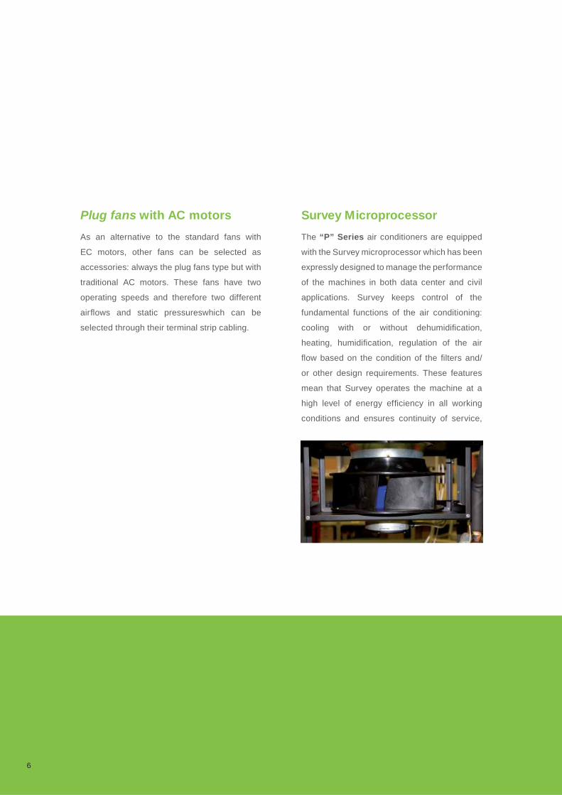
The fan section is made up by one or more
backward curved, free running impeller, radial
fans (plug fan) which are particularly silent
in operation. Apart from offering very high
performance plug fans also guarantee easy
cleaning the blades. These fans are fi tted as
standard with EC (electronically commutated)
constant current brushless motors with external
rotors and are the latest innovation concerning
energy saving in the fan sector.
EC motors are about 25-30% more effi cient than
normal asynchronous alternating current motors.
They also allow continuous speed variation
depending on the external sensor signal on the
microprocessor control of the machine, without
the need for an inverter or other electronic
devices. At equal operating conditions, the
combination of EC motors and plug fans therefore
offers remarkable advantages in many areas:
functionality, energy effi ciency, low sound level,
absence of vibration in operation and soft start
(less current absorbed on starting).
Four alternatives for regulation
Aermec provides four different alternatives
for the regulation of the airfl ow of the EC
fans depending on the requirements of the
installation:
1. Constant fan rotation speed. The available
high static pressure is ideal for most applications.
The effective air fl ow is the consequence of
the real pressure drop of the aeraulic system
of the installation; it can however be calculated
through AERMEC’s computerized selection
program.
2. Constant airfl ow independent of the
pressure drop of the fi lters. An internal
4
sensor guides the microprocessor management
system to vary the airfl ow handled by the fan,
depending on the degree of clogging of the
fi lters, in order to maintain a constant airfl ow.
This makes sure that insuffi cient cooling does
not occur due to reduced airfl ow arising from
dirty fi lters. AERMEC recommends this type of
regulation when F7 fi lters are used, in order to
increase their working life.
3. Variable airfl ow depending on the cooling
capacity required by the installation. This
is the classic VAV (Variable Air Volume) plant
arrangement which responds to increased
demand by a proportionate increase in airfl ow
and vice versa. As has been noted, this type
of plant offers interesting energy advantages at
partial loads, which occur extensively throughout
the year, especially at night. The VAV system,
which is recommended only for chilled water
machines, requires that modulating regulation
of the cooling capacity is provided.
4. Airfl ow as a function of pressure in the
raised fl oor. This regulation alternative is
envisaged for plants with raised fl oors where
the air is distributed under the fl oor itself. The
Survey microprocessor management system
maintains constant under-fl oor pressure. In
particular, in very large areas subdivided into
multiple local zones with partition dampers
driven by individual thermostats, constant
regulation of the pressure is necessary in
order to avoid imbalances in the distribution
of the air. In fact, without correct fan speed
regulation, the closure of one or more of the
dampers could cause an excessive increase
in the airfl ow through the dampers remaining
open. A pressure sensor is included to be
installed in a representative under-fl oor point
to guide the Survey which, in its turn, regulates
the fan speed in order to maintain the designed
pressure values.
5
Plug fans with AC motors
As an alternative to the standard fans with
EC motors, other fans can be selected as
accessories: always the plug fans type but with
traditional AC motors. These fans have two
operating speeds and therefore two different
airfl ows and static pressureswhich can be
selected through their terminal strip cabling.
Survey Microprocessor
The “P” Series air conditioners are equipped
with the Survey microprocessor which has been
expressly designed to manage the performance
of the machines in both data center and civil
applications. Survey keeps control of the
fundamental functions of the air conditioning:
cooling with or without dehumidifi cation,
heating, humidifi cation, regulation of the air
fl ow based on the condition of the fi lters and/
or other design requirements. These features
mean that Survey operates the machine at a
high level of energy effi ciency in all working
conditions and ensures continuity of service,
6
even in emergency situations, if the machines
are equipped with two compressors or the
plant has multiple machines. Survey has a wide
range of auto-diagnosis functions and can also
completely manage all the alarms.
Scroll compressors
Extremely quiet scroll compressors with high
energy effi ciency have been installed in the
direct expansion units. They offer a signifi cant
reduction in energy consumption and therefore
allow the impact on the environment to be
limited. In fact, scroll compressors give higher
volumetric performance than alternative ones
at equal yield capacity. In addition, the absence
of valves eliminates the pressure drop which
is characteristic of the alternatives, allowing
an increase in energy effi ciency in equal
conditions. The scroll compressors used in the
“P” Series air conditioners are selected from
the most effi cient and reliable models available
from highly qualifi ed international constructors.
Single or double refrigerant circuitThe models with “1” as the last digit of the
numerical part of the identifi cation code have
a single circuit and a single compressor. Those
with “2” as the last digit on the other hand have
two completely independent refrigerant circuits
and two compressors.
The installation designer can therefore choose
to use a single compressor machine or one with
two compressors which offers 50% redundancy.
The circuits are fi tted with all the safety and
regulation devices necessary for effi cient and
7

reliable operation. The evaporator coil can
be single or double circuit depending on the
number of compressors.
Electronic expansion valve
Electronic expansion valves are one of the
most recent pieces of equipment to improve
the energy effi ciency at partial loads of direct
expansion machines. These valves are installed
at the inlet of the evaporator, substituting the
traditional thermostatic expansion ones. This
permits much more precise control of the
quantity of refrigerant entering the evaporator
dependent on the effective requirement of
the load, thus guaranteeing good capacity
regulation between 100% and 50%.
Electronic expansion valves also enable the
amount of overheated gas at the outlet of the
evaporator to be controlled, thus allowing
a signifi cant reducing of the condensation
pressure during winter or night-time operation
whilst maintaining the evaporation pressure
unchanged. Adopting the electronic expansion
valve (accessory) guarantees a signifi cant
increase in the EER.
Ecological refrigerants
The machines with direct expansion cooling
system use the R-410A refrigerant, which does
not damage the ozone layer.
8

Very high effi ciency heat exchanger coil
The copper-aluminium coils fi tted to direct
expansion machines with downward air
discharge can have, as accessory, a hydrophilic
surface treatment to the fi ns in order to
prevent any downward condensate drag. This
treatment, which penalises the heat exchange
of the fi ns, therefore necessitates an increase
in the size of the coils and is required whenever
the environment has to be dehumidifi ed. It
therefore has to be specifi ed when many
operators are present or when there are large
volumes of fresh air. In machines with chilled
water coils, the hydrophilic treatment is not
envisaged as dehumidifi cation is in fact non-
existent due to the temperatures of the supply
water being always higher in order to exploit the
free cooling effect (up to 20°C in data centers
with hot pool air distribution), the non-presence
of operators, and to the absence of any kind
of humidity: this surface treatment, as stated
above, reduces the heat exchange and so
requires coils with more rows and is therefore
totally unfruitful. The aluminium fi ns have
specialization of the TURBO/COIL® profi le,
perfected in the LU-VE SpA research labs.
They produce a predetermined turbulence of
the crossing air which therefore increases the
coeffi cient of heat exchange.
The copper tubes have the special TURBO/
FIN® internal helical grooves which centrifuge
the liquid refrigerant fl ow thus optimising the
capacity of heat exchange between air and
refrigerant.
9
Refrigerant and oil charge
OPA e UPA mono-block air conditioners with
incorporated water condenser (accessory)
are supplied complete with refrigerant and oil
charge.
OPA e UPA air conditioners for connecting
to remote condensers are supplied only with
nitrogen pressurized charge and the standard
oil charge of the compressor(s). The refrigerant
charge and any topping-up of the oil level has
to be done by the installer during the installation
process.
Hydraulic circuit and regulation valves The chilled water units are fi tted with a fi n-pack
type heat exchanger coil with several rows,
copper tubes and aluminium fi ns. The coils have
as standard a motorized three-way valve for the
fl oating regulation of the water fl ow. The coils
are designed to give maximum performance
in the two regimes typical of chilled water
temperatures:
- 15/20 °C, or higher, as required by most data
centres, telephone exchanges etc;
- 7/12 °C, mainly for wellness applications in
the civil sector.
In both cases, the standard fl oating regulation
allows the progressive modulation of the cooling
capacity based on the demand for cooling the
environment without any sudden variations
which could cause discomfort. Nevertheless a
modulating valve is available as an accessory,
installed in place of the fl oating one when very
precise regulation of the cooling capacity is
required. It is also very suitable for those cases
which involve high rates of fresh air.
If the plant is equipped with variable fl ow pumps,
two-way valves with modulating regulation can
be fi tted instead of three-way ones.
10
Local network and remote management
With Survey, it is possible to operate the “P”
Series air conditioners both by local network
with multiple units (up to 12) in one place or by
remote management.
In local network applications, one machine
is the slave and the others are master. The
slave unit comes into operation in emergency
situations or when peak demand exceeds the
design values. The slave units are rotated at
predetermined intervals (for example every 12
or 24 hours) and switch to the master role to
balance the number of working hours of the
compressors.
In remote applications, the machines can be
controlled from remote positions via modem
or via supervision software developed by
Aermec.
For applications involving remote control of
the unit, supervsing systems and interface to
Building Management Systems (BMS) the units
can be equiped with a RS485 card working with
MODBUS RTU protocol.
Further Gateway’s are available for interfacing
more units (up to 12 units to 1 gateway) to other
important Serial Communication Protocols:
- Lonwaorks FTT10
- Bacnet MS/TP or TCP/IP
- TCP/IP Ethernet
- TCP/IP Ethernet with an integrated GSM
modem.
Electrical boards
The “P” Series air conditioners have electrical
boards with complete safety protection in
accordance with EU and the principle international
regulations. There is a main switch with shutter-
block function, in addition to magneto-thermic
switches and contactors. There are terminals
for switching on and off the machine by remote
control, and other free terminals for the remote
indication of a cumulative alarm. The machines
with compressors have phase sequencers as
11
standard in order to protect the compressors
from any damage should the machine start up
in the opposite direction from normal. Remote
condenser fan speed regulators are also
available as accessories.
Large surface-area fi lters
Adequate air fi ltration is an especially important
requirement in data centers in order to prevent
damage to information technology equipment
caused by air-dispersed particles which can
also carry corrosive substances. But also is
civil applications, IAQ (indoor air quality) control
is a topic of ever-growing importance.
To satisfy this demand, Aermec equips its “P”
Series air conditioners as standard with re-
generable self-extinguishing class G4 fi lters.
Alternatively, they can be substituted with high
effi ciency F7 air fi lters if a more rigorous control
of the IAQ is required. The fi lters are installed,
upstream of the cooling coil, in an inclined
position. Their large surface allows lower air
crossing speeds and therefore lower energy
consumption.
12
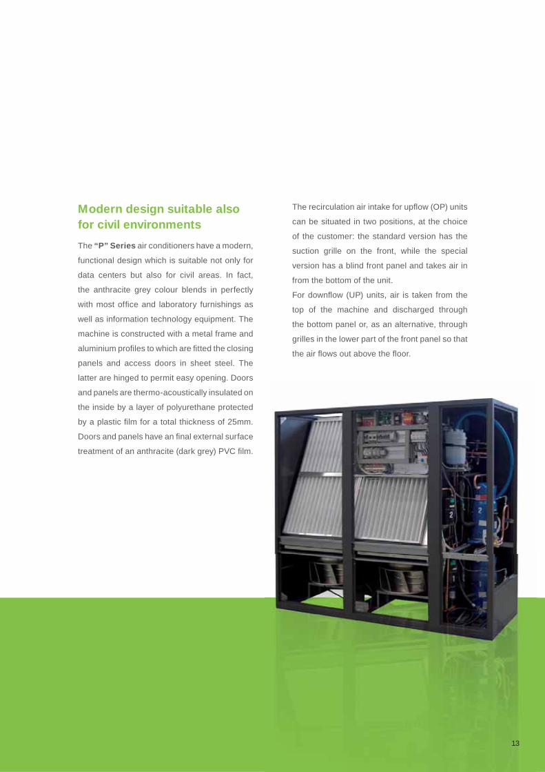
Modern design suitable also for civil environments
The “P” Series air conditioners have a modern,
functional design which is suitable not only for
data centers but also for civil areas. In fact,
the anthracite grey colour blends in perfectly
with most offi ce and laboratory furnishings as
well as information technology equipment. The
machine is constructed with a metal frame and
aluminium profi les to which are fi tted the closing
panels and access doors in sheet steel. The
latter are hinged to permit easy opening. Doors
and panels are thermo-acoustically insulated on
the inside by a layer of polyurethane protected
by a plastic fi lm for a total thickness of 25mm.
Doors and panels have an fi nal external surface
treatment of an anthracite (dark grey) PVC fi lm.
The recirculation air intake for upfl ow (OP) units
can be situated in two positions, at the choice
of the customer: the standard version has the
suction grille on the front, while the special
version has a blind front panel and takes air in
from the bottom of the unit.
For downfl ow (UP) units, air is taken from the
top of the machine and discharged through
the bottom panel or, as an alternative, through
grilles in the lower part of the front panel so that
the air fl ows out above the fl oor.
13
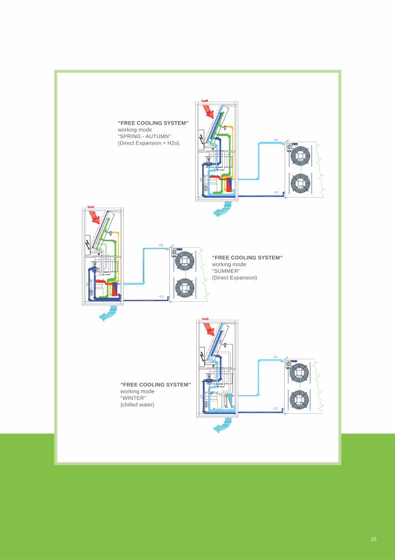
“Free cooling” air-water: using renewable energy
This system (accessory) uses external air - a
source of renewable energy - instead of or in
addition to mechanical cooling. Envisaged
for the OPA/FC - UPA/FC air conditioners,
it consists of a cold water coil integrated with
the direct expansion one with a three way
modulating valve controlled by microprocessor.
Three different operating regimes are therefore
possible:
Only free cooling. This occurs when the
external air temperature is suffi ciently low to
bring the water circulating in the coil to a value
which fulfi ls the requirements of cooling in the
data center, or more generally, in the area to
be acclimatized. This is the maximum energy
saving scenario as the compressors are always
out of service.
Free cooling + mechanical cooling. If the
external air temperature is higher than that
necessary to maintain the water cooling at the
desired temperature, one or more compressors
are switched on for the strategic length of time
necessary to reach the desired conditions.
This too is an energy saving situation, even if
the savings are not as high as the preceding
example.
Only mechanical cooling without free
cooling. This situation arises when the
temperature of the external air is too high
to produce suffi cient cooling. In this case
the compressors function as normal. This
operation exploits to the full the high energy
effi ciency of the refrigerant circuits thanks to
the larger size of the coil’s fi n pack. So even
using only mechanical cooling helps to keep
energy consumption down compared to other
systems.
The water cooled condensers of the refrigerant
circuit are provided with a pressure-switch
system to regulate the condensing pressure
(accessory).
14
15
“FREE COOLING SYSTEM”working mode“SPRING - AUTUMN”(Direct Expansion + H2o).
“FREE COOLING SYSTEM”working mode“SUMMER”(Direct Expansion)
“FREE COOLING SYSTEM”working mode“WINTER”(chilled water)
“Two sources” for the maximum safety of continuity of operation or the use of excess energy from a centralized installation
Instead of using a free cooling circuit, this system
(accessory) uses any available excess energy
from the air conditioning plant of the building.
In other words, when there is enough cooling
energy available from the central air conditioning
plant, the unit stops its own compressors and
uses the cooled water thus made available,
passing it through the same water coil installed
in the free cooling air conditioners.
One advantage of this system is that it can be
used in emergency situations: if a dedicated
cooling group breaks down, it will maintain a
continuity of service thanks to the cooled water
from the central plant.
The “two sources” typology is very fl exible.
The second source can be both by direct
expansion or chilled water and the priority of
operation can be chosen depending on the
requirements of the installation.
16

17
“TWO SOURCES SYSTEM”working mode“DIRECT EXPANSION”
“TWO SOURCES SYSTEM”working mode“CHILLED WATER”

Accessories
Numerous accessories and options are
available for the “P” Series air conditioners
to personalize the installation depending on
the requirements of the plant and its design.
Divided by function, they include:
Free cooling or two sources
Additional Free cooling circuit.
Additional Two sources circuit.
Alarms
Water alarm (supplied loose).
Out-of-range air discharge temperature
alarm.
Smoke/fire alarm terminals.
Water cooled condensers and pressostatic
valves
Welded stainless steel water cooled plate
condenser.
2 way pressostatic valve (only if the water
condenser is selected).
Sound proofi ng devices
Sound damped duct for air suction or
discharge.(h=550 mm). Allows a reduction
of approx.4 dB(A) of the SPL of the unit.
Double layer sound damping panels.
Reduces SPL by approx 2 dB(A) in upflow
units (OP series), and approx.4 dB(A) in
downflow units ((UP series).
Double-layer “sandwich” thermo-acoustic
insulation panels.
Panels and base
Blind front panel (OP) and open base for
bottom air intake.
Front panel with grille in the lower part (UP)
and closed base.
Plenum
Plenum (h=550 mm) for air discharge or
intake with front grille.
Plenum (h=550 mm) for air discharge or
intake with front and side grilles.
18
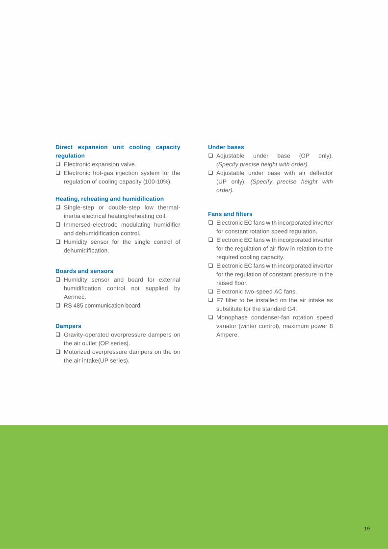
Direct expansion unit cooling capacity
regulation
Electronic expansion valve.
Electronic hot-gas injection system for the
regulation of cooling capacity (100-10%).
Heating, reheating and humidifi cation
Single-step or double-step low thermal-
inertia electrical heating/reheating coil.
Immersed-electrode modulating humidifier
and dehumidification control.
Humidity sensor for the single control of
dehumidification.
Boards and sensors
Humidity sensor and board for external
humidification control not supplied by
Aermec.
RS 485 communication board.
Dampers
Gravity-operated overpressure dampers on
the air outlet (OP series).
Motorized overpressure dampers on the on
the air intake(UP series).
Under bases
Adjustable under base (OP only).
(Specify precise height with order).
Adjustable under base with air deflector
(UP only). (Specify precise height with
order).
Fans and fi lters
Electronic EC fans with incorporated inverter
for constant rotation speed regulation.
Electronic EC fans with incorporated inverter
for the regulation of air flow in relation to the
required cooling capacity.
Electronic EC fans with incorporated inverter
for the regulation of constant pressure in the
raised floor.
Electronic two-speed AC fans.
F7 filter to be installed on the air intake as
substitute for the standard G4.
Monophase condenser-fan rotation speed
variator (winter control), maximum power 8
Ampere.
19

AE
RM
EC
Performance as the test conditions AERMECYC-PXO: direct expansion air conditioners with air cooled or water condensers and up-fl ow air supply
YC-PXU: direct expansion air conditioners with air cooled or water condensers and down-fl ow air supply
Models 71 111 141 211 251 301 302 372 361 461 422 512 612 662 852 932
Performance
Tot. cooling cap. kW: 7,2 11,2 14,3 20,9 25,2 30,4 30,6 38,2 47,2 42,2 51,2 64,3 67,5 84,3 96,0
Sens cooling cap. kW: 6,7 10,6 11,8 19,8 21,7 29,4 27,7 31,0 46,2 41,5 45,0 58,2 59,8 67,3 83,5
Airfl ow m3/h: 2200 3200 3200 7000 7000 8700 8.700 8.700 14.500 14.500 14.500 14.500 17.900 17.900 17.900 22.500
EER 3,09 3,11 3,15 3,12 3,05 3,10 3,18 2,96 3,38 3,12 3,06 3,21 3,11 3,14 3,41
LPS:dB(A) 49 49 49 56 56 58 58 58 63 63 63 63 68 68 68 69
Dimensions & weight
Lenght mm. 750 750 750 860 860 750 1.410 1.410 1.750 1.750 1.750 1.750 2.300 2.300 2.300 2.640
Depth mm. 630 630 630 880 880 880 880 880 880 880 880 880 880 880 880 880
Height mm. 1990 1990 1990 1.990 1.990 1965 1.990 1.990 1.990 1.990 1.990 1.990 990 990 990 1.990
Net weight kg. 170 170 170 210 270 270 300 315 330 400 420 440 420 490 315 330
Models 71 111 141 211 251 301 302 372 361 461 422 512 612 662 852 932
Performance
Tot. cooling cap. kW: 7,2 11,2 14,3 20,9 25,2 30,4 30,6 38,2 47,2 42,2 51,2 64,3 67,5 84,3 96,0
Sens cooling cap. kW: 6,7 10,6 11,8 19,8 21,7 29,4 27,7 31,0 46,2 41,5 45,0 58,2 59,8 67,3 83,5
Airfl ow m3/h: 2200 3200 3200 7000 7000 8700 8.700 8.700 14.500 14.500 14.500 14.500 17.900 17.900 17.900 22.500
EER 3,09 3,11 3,15 3,12 3,05 3,10 3,18 2,96 3,38 3,12 3,06 3,21 3,11 3,14 3,41
LPS:dB(A) 49 49 49 56 56 58 58 58 63 63 63 63 68 68 68 69
Dimensions & weight
Lenght mm. 750 750 750 860 860 750 1.410 1.410 1.750 1.750 1.750 1.750 2.300 2.300 2.300 2.640
Depth mm. 630 630 630 880 880 880 880 880 880 880 880 880 880 880 880 880
Height mm. 1990 1990 1990 1.990 1.990 1965 1.990 1.990 1.990 1.990 1.990 1.990 990 990 990 1.990
Net weight kg. 170 170 170 210 255 270 300 315 330 400 420 440 420 470 315 330
20

Notes:
The performances are referred to: refrigerant R410; condensing temperature: 45°C; inlet air: 24°C - 50% RH; for chilled water: 7/12°C; The SPL is referred to 2 m distance, 1,5 m height, free fi eld and sound damped discharge mouth. Available static pressure: 30 Pa. EER = Electro Effi ciency Ratio = Total cooling capacity / compressors power input + fans power input. The above performances don’t consider the heat generated by the fans which must be added to the thermal load of the system.
AE
RM
EC
Performance as the test conditions AERMECYC-PWO: with chilled water coil and up-fl ow air supply
YC-PWU: with chilled water coil and down-fl ow air supply
Models 10 20 30 50 80 110 160 220
Performance
Tot. cooling cap. kW: 10,6 19,6 31,4 41,3 71,2 92,5 148,4
Sens cooling cap. kW: 9,9 17,2 31,4 38,8 68,0 83,2 131,2
Airfl ow m3/h: 2200 3400 7800 8.300 16000 17.000 26.400
LPS:dB(A) 47 49 57 56 59 61 64
Dimensions & weight
Lenght mm. 750 750 860 860 1750 1.750 2.640
Depth mm. 630 630 880 880 880 880 880
Height mm. 1990 1990 1990 1990 1990 1.990 1.990
Net weight kg. 155 155 180 250 450 450 650
Models 10 20 30 50 80 110 160 220
Performance 11,1 19,3 30,6 39 69,2 88 151 175,8
Tot. cooling cap. kW: 8,4 13,8 24,5 30 53 64,9 106,5 129,5
Sens cooling cap. kW: 2.400 3.500 7.800 8.300 16.000 17.000 26.400 34.000
Airfl ow m3/h: 20 20 75 75 75 75 75 75
LPS:dB(A) 82 82 80 78 83 81 84 84
Dimensions & weight
Lenght mm. 750 750 860 860 1.750 1.750 2.640 3.495
Depth mm. 630 630 880 880 880 880 880 880
Height mm. 1.990 1.990 1.990 1.990 1.990 1.990 1.990 1.990
Net weight kg. 155 155 180 250 450 450 650
21
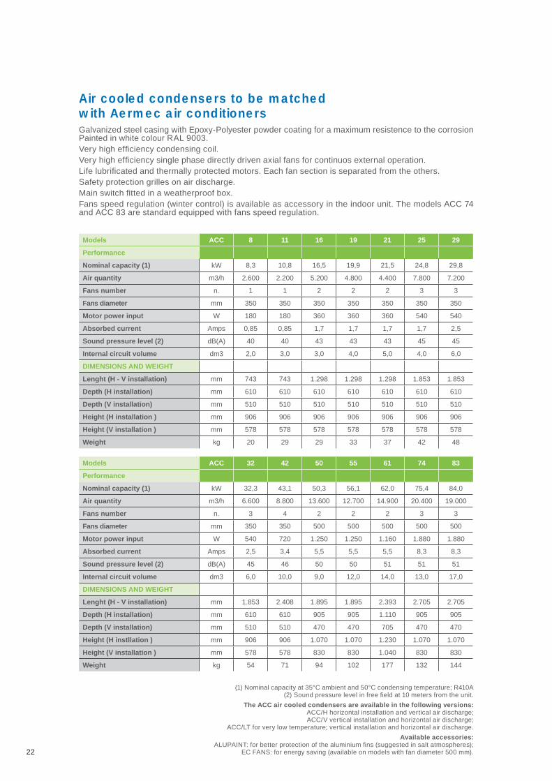
Air cooled condensers to be matched with Aermec air conditionersGalvanized steel casing with Epoxy-Polyester powder coating for a maximum resistence to the corrosion Painted in white colour RAL 9003.Very high effi ciency condensing coil.Very high effi ciency single phase directly driven axial fans for continuos external operation.Life lubrifi cated and thermally protected motors. Each fan section is separated from the others.Safety protection grilles on air discharge.Main switch fi tted in a weatherproof box.Fans speed regulation (winter control) is available as accessory in the indoor unit. The models ACC 74 and ACC 83 are standard equipped with fans speed regulation.
Models ACC 8 11 16 19 21 25 29
Performance
Nominal capacity (1) kW 8,3 10,8 16,5 19,9 21,5 24,8 29,8
Air quantity m3/h 2.600 2.200 5.200 4.800 4.400 7.800 7.200
Fans number n. 1 1 2 2 2 3 3
Fans diameter mm 350 350 350 350 350 350 350
Motor power input W 180 180 360 360 360 540 540
Absorbed current Amps 0,85 0,85 1,7 1,7 1,7 1,7 2,5
Sound pressure level (2) dB(A) 40 40 43 43 43 45 45
Internal circuit volume dm3 2,0 3,0 3,0 4,0 5,0 4,0 6,0
DIMENSIONS AND WEIGHT
Lenght (H - V installation) mm 743 743 1.298 1.298 1.298 1.853 1.853
Depth (H installation) mm 610 610 610 610 610 610 610
Depth (V installation) mm 510 510 510 510 510 510 510
Height (H installation ) mm 906 906 906 906 906 906 906
Height (V installation ) mm 578 578 578 578 578 578 578
Weight kg 20 29 29 33 37 42 48
Models ACC 32 42 50 55 61 74 83
Performance
Nominal capacity (1) kW 32,3 43,1 50,3 56,1 62,0 75,4 84,0
Air quantity m3/h 6.600 8.800 13.600 12.700 14.900 20.400 19.000
Fans number n. 3 4 2 2 2 3 3
Fans diameter mm 350 350 500 500 500 500 500
Motor power input W 540 720 1.250 1.250 1.160 1.880 1.880
Absorbed current Amps 2,5 3,4 5,5 5,5 5,5 8,3 8,3
Sound pressure level (2) dB(A) 45 46 50 50 51 51 51
Internal circuit volume dm3 6,0 10,0 9,0 12,0 14,0 13,0 17,0
DIMENSIONS AND WEIGHT
Lenght (H - V installation) mm 1.853 2.408 1.895 1.895 2.393 2.705 2.705
Depth (H installation) mm 610 610 905 905 1.110 905 905
Depth (V installation) mm 510 510 470 470 705 470 470
Height (H instllation ) mm 906 906 1.070 1.070 1.230 1.070 1.070
Height (V installation ) mm 578 578 830 830 1.040 830 830
Weight kg 54 71 94 102 177 132 144
22
(1) Nominal capacity at 35°C ambient and 50°C condensing temperature; R410A(2) Sound pressure level in free fi eld at 10 meters from the unit.
The ACC air cooled condensers are available in the following versions:ACC/H horizontal installation and vertical air discharge;ACC/V vertical installation and horizontal air discharge;
ACC/LT for very low temperature; vertical installation and horizontal air discharge.
Available accessories:ALUPAINT: for better protection of the aluminium fi ns (suggested in salt atmospheres);
EC FANS: for energy saving (available on models with fan diameter 500 mm).

york® airside products
Delivering precision air conditioning for critical applications
SerieR410A
![[PWU-13-10] [RES-1302] Art Forms and Architecture](https://static.fdocuments.in/doc/165x107/577ccfe31a28ab9e7890d7a4/pwu-13-10-res-1302-art-forms-and-architecture.jpg)


![[PWU 13 04] [RES 1321] Disaster Management](https://static.fdocuments.in/doc/165x107/577cc69f1a28aba7119eb21c/pwu-13-04-res-1321-disaster-management.jpg)