AIR CONDITIONER HA -...
98
HEATER & AIR CONDITIONER SECTION HA CONTENTS PRECAUTIONS ...............................................................2 Supplemental Restraint System (SRS) ″AIR BAG″ and ″SEAT BELT PRE-TENSIONER″ ...............2 Precautions for Working with HFC-134a (R-134a) .....2 General Refrigerant Precautions .................................2 Precautions for Refrigerant Connection ......................3 Precautions for Servicing Compressor ........................5 Precautions for Service Equipment .............................6 Wiring Diagrams and Trouble Diagnosis .....................8 PREPARATION ...............................................................9 Special Service Tools ..................................................9 HFC-134a (R-134a) Service Tools and Equipment .................................................................. 11 DESCRIPTION ...............................................................13 Refrigeration System .................................................13 CSV613 Variable Displacement Compressor............14 Component Layout ....................................................18 Control Operation ......................................................19 Discharge Air Flow.....................................................20 System Description ....................................................21 TROUBLE DIAGNOSES................................................22 Component Location..................................................22 Wiring Diagram - Heater............................................24 Circuit Diagram - Air Conditioner...............................26 Wiring Diagram - A/C, M - .........................................27 How to Perform Trouble Diagnoses for Quick and Accurate Repair ..................................................33 Operational Check .....................................................34 Intake Door ................................................................36 Mode Door .................................................................40 Air Mix Door ...............................................................42 Max Hot Door (For Scandinavia and Cold Spec Models) ......................................................................44 Blower Motor..............................................................48 Magnet Clutch............................................................55 Insufficient Cooling ....................................................68 Insufficient Heating ....................................................76 Noise ..........................................................................77 SERVICE PROCEDURE................................................78 HFC-134a (R-134a) Service Procedure ....................78 Maintenance of Lubricant Quantity in Compressor ...............................................................80 Compressor ...............................................................83 Compressor Clutch - CSV613 (CALSONIC make) .........................................................................84 Heater & Cooling Unit (Heater Core) ........................88 A/C Evaporator ..........................................................88 Blower Unit ................................................................89 Refrigerant Lines .......................................................91 Belt .............................................................................95 Idle Air Control Valve (IACV) - Auxiliary Air Control (AAC) Valve ..................................................96 Ventilation Air Filter ....................................................96 SERVICE DATA AND SPECIFICATIONS (SDS) .........97 Compressor ...............................................................97 Lubricant ....................................................................97 Refrigerant .................................................................97 Engine Idling Speed (When A/C is On).....................97 Belt Tension ...............................................................97
Transcript of AIR CONDITIONER HA -...

HEATER &AIR CONDITIONER
SECTIONHACONTENTS
PRECAUTIONS ...............................................................2Supplemental Restraint System (SRS) ″AIRBAG″ and ″SEAT BELT PRE-TENSIONER″...............2Precautions for Working with HFC-134a (R-134a) .....2General Refrigerant Precautions .................................2Precautions for Refrigerant Connection ......................3Precautions for Servicing Compressor........................5Precautions for Service Equipment .............................6Wiring Diagrams and Trouble Diagnosis.....................8
PREPARATION ...............................................................9Special Service Tools ..................................................9HFC-134a (R-134a) Service Tools andEquipment..................................................................11
DESCRIPTION ...............................................................13Refrigeration System .................................................13CSV613 Variable Displacement Compressor............14Component Layout ....................................................18Control Operation ......................................................19Discharge Air Flow.....................................................20System Description....................................................21
TROUBLE DIAGNOSES ................................................22Component Location..................................................22Wiring Diagram - Heater............................................24Circuit Diagram - Air Conditioner...............................26Wiring Diagram - A/C, M - .........................................27How to Perform Trouble Diagnoses for Quickand Accurate Repair ..................................................33Operational Check .....................................................34Intake Door ................................................................36Mode Door .................................................................40
Air Mix Door...............................................................42Max Hot Door (For Scandinavia and Cold SpecModels) ......................................................................44Blower Motor..............................................................48Magnet Clutch............................................................55Insufficient Cooling ....................................................68Insufficient Heating ....................................................76Noise..........................................................................77
SERVICE PROCEDURE................................................78HFC-134a (R-134a) Service Procedure ....................78Maintenance of Lubricant Quantity inCompressor ...............................................................80Compressor ...............................................................83Compressor Clutch - CSV613 (CALSONICmake) .........................................................................84Heater & Cooling Unit (Heater Core) ........................88A/C Evaporator ..........................................................88Blower Unit ................................................................89Refrigerant Lines .......................................................91Belt.............................................................................95Idle Air Control Valve (IACV) - Auxiliary AirControl (AAC) Valve ..................................................96Ventilation Air Filter....................................................96
SERVICE DATA AND SPECIFICATIONS (SDS) .........97Compressor ...............................................................97Lubricant ....................................................................97Refrigerant .................................................................97Engine Idling Speed (When A/C is On).....................97Belt Tension ...............................................................97

Supplemental Restraint System (SRS) “AIRBAG” and “SEAT BELT PRE-TENSIONER”
NJHA0190
The Supplemental Restraint System such as “AIR BAG” and “SEAT BELT PRE-TENSIONER” used along witha seat belt, helps to reduce the risk or severity of injury to the driver and front passenger for certain types ofcollision. The SRS system composition which is available to NISSAN MODEL N16 is as follows (The compo-sition varies according to the destination and optional equipment.):+ For a frontal collision
The Supplemental Restraint System consists of driver air bag module (located in the center of the steer-ing wheel), front passenger air bag module (located on the instrument panel on passenger side), front seatbelt pre-tensioners, a diagnosis sensor unit, warning lamp, wiring harness and spiral cable.
+ For a side collisionThe Supplemental Restraint System consists of front side air bag module (located in the outer side of frontseat), side air bag (satellite) sensor, diagnosis sensor unit (one of components of air bags for a frontalcollision), wiring harness, warning lamp (one of components of air bags for a frontal collision).
Information necessary to service the system safely is included in the RS section of this Service Manual.WARNING:+ To avoid rendering the SRS inoperative, which could increase the risk of personal injury or death
in the event of a collision which would result in air bag inflation, all maintenance should be per-formed by an authorized NISSAN dealer.
+ Improper maintenance, including incorrect removal and installation of the SRS, can lead to per-sonal injury caused by unintentional activation of the system. For removal of Spiral Cable and AirBag Module, see the RS section.
+ Do not use electrical test equipment on any circuit related to the SRS unless instructed to in thisService Manual. Spiral cable and wiring harnesses covered with yellow insulation tape either justbefore the harness connectors or for the complete harness are related to the SRS.
Precautions for Working with HFC-134a(R-134a)
NJHA0113
WARNING:+ CFC-12 (R-12) refrigerant and HFC-134a (R-134a) refrigerant are not compatible. These refrigerants
must never be mixed, even in the smallest amounts. If the refrigerants are mixed, compressor fail-ure is likely to occur.
+ Use only specified lubricant for the HFC-134a (R-134a) A/C system and HFC-134a (R-134a) compo-nents. If lubricant other than that specified is used, compressor failure is likely to occur.
+ The specified HFC-134a (R-134a) lubricant rapidly absorbs moisture from the atmosphere. The fol-lowing handling precautions must be observed:
a) When removing refrigerant components from a vehicle, immediately cap (seal) the component tominimize the entry of moisture from the atmosphere.
b) When installing refrigerant components to a vehicle, do not remove the caps (unseal) until justbefore connecting the components. Connect all refrigerant loop components as quickly as pos-sible to minimize the entry of moisture into system.
c) Only use the specified lubricant from a sealed container. Immediately reseal containers of lubri-cant. Without proper sealing, lubricant will become moisture saturated and should not be used.
d) Avoid breathing A/C refrigerant and lubricant vapor or mist. Exposure may irritate eyes, noseand throat. Remove R-134a from the A/C system, using certified service equipment meetingrequirements of R-134a recycling equipment, or R-134a recovery equipment. If accidental systemdischarge occurs, ventilate work area before resuming service. Additional health and safetyinformation may be obtained from refrigerant and lubricant manufacturers.
e) Do not allow lubricant (Nissan A/C System Oil Type S) to come in contact with styrofoam parts.Damage may result.
General Refrigerant PrecautionsNJHA0114
WARNING:+ Do not release refrigerant into the air. Use approved recovery/recycling equipment to capture the
refrigerant every time an air conditioning system is discharged.+ Always wear eye and hand protection (goggles and gloves) when working with any refrigerant or
air conditioning system.
PRECAUTIONSSupplemental Restraint System (SRS) “AIR BAG” and “SEAT BELT PRE-TENSIONER”
HA-2

+ Do not store or heat refrigerant containers above 52°C (125°F).+ Do not heat a refrigerant container with an open flame; if container warming is required, place the
bottom of the container in a warm pail of water.+ Do not intentionally drop, puncture, or incinerate refrigerant containers.+ Keep refrigerant away from open flames: poisonous gas will be produced if refrigerant burns.+ Refrigerant will displace oxygen, therefore be certain to work in well ventilated areas to prevent
suffocation.+ Do not pressure test or leak test HFC-134a (R-134a) service equipment and/or vehicle air condi-
tioning systems with compressed air during repair. Some mixtures of air and R-134a have beenshown to be combustible at elevated pressures. These mixtures, if ignited, may cause injury orproperty damage. Additional health and safety information may be obtained from refrigerant manu-facturers.
Precautions for Refrigerant ConnectionNJHA0115
A new type refrigerant connection has been introduced to all refrigerant lines except the following portion.+ Expansion valve to cooling unit
FEATURES OF NEW TYPE REFRIGERANT CONNECTIONNJHA0115S01
+ The O-ring has been relocated. It has also been provided with a groove for proper installation. This elimi-nates the chance of the O-ring being caught in, or damaged by, the mating part. The sealing direction ofthe O-ring is now set vertically in relation to the contacting surface of the mating part to improve sealingcharacteristics.
+ The reaction force of the O-ring will not occur in the direction that causes the joint to pull out, therebyfacilitating piping connections.
SHA815E
PRECAUTIONSGeneral Refrigerant Precautions (Cont’d)
HA-3
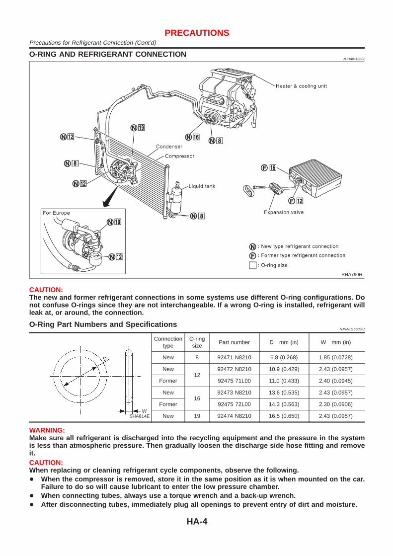
O-RING AND REFRIGERANT CONNECTIONNJHA0115S02
RHA790H
CAUTION:The new and former refrigerant connections in some systems use different O-ring configurations. Donot confuse O-rings since they are not interchangeable. If a wrong O-ring is installed, refrigerant willleak at, or around, the connection.
O-Ring Part Numbers and SpecificationsNJHA0115S0201
SHA814E
Connectiontype
O-ringsize
Part number D mm (in) W mm (in)
New 8 92471 N8210 6.8 (0.268) 1.85 (0.0728)
New12
92472 N8210 10.9 (0.429) 2.43 (0.0957)
Former 92475 71L00 11.0 (0.433) 2.40 (0.0945)
New16
92473 N8210 13.6 (0.535) 2.43 (0.0957)
Former 92475 72L00 14.3 (0.563) 2.30 (0.0906)
New 19 92474 N8210 16.5 (0.650) 2.43 (0.0957)
WARNING:Make sure all refrigerant is discharged into the recycling equipment and the pressure in the systemis less than atmospheric pressure. Then gradually loosen the discharge side hose fitting and removeit.CAUTION:When replacing or cleaning refrigerant cycle components, observe the following.+ When the compressor is removed, store it in the same position as it is when mounted on the car.
Failure to do so will cause lubricant to enter the low pressure chamber.+ When connecting tubes, always use a torque wrench and a back-up wrench.+ After disconnecting tubes, immediately plug all openings to prevent entry of dirt and moisture.
PRECAUTIONSPrecautions for Refrigerant Connection (Cont’d)
HA-4

+ When installing an air conditioner in the vehicle, connect the pipes as the final stage of the opera-tion. Do not remove the seal caps of pipes and other components until just before required forconnection.
+ Allow components stored in cool areas to warm to working area temperature before removing sealcaps. This prevents condensation from forming inside A/C components.
+ Thoroughly remove moisture from the refrigeration system before charging the refrigerant.+ Always replace used O-rings.+ When connecting tube, apply lubricant to circle of the O-rings shown in illustration. Be careful not
to apply lubricant to threaded portion.Lubricant name: Nissan A/C System Oil Type R for DKV-11G compressorPart number: KLH00-PAGR0Lubricant name: Nissan A/C System Oil Type S for CSV613 compressorPart number: KLH00-PAGS0
+ O-ring must be closely attached to dented portion of tube.+ When replacing the O-ring, be careful not to damage O-ring and tube.+ Connect tube until you hear it click, then tighten the nut or bolt by hand until snug. Make sure that
the O-ring is installed to tube correctly.+ After connecting line, conduct leak test and make sure that there is no leakage from connections.
When the gas leaking point is found, disconnect that line and replace the O-ring. Then tightenconnections of seal seat to the specified torque.
RHA861F
Precautions for Servicing CompressorNJHA0116
+ Plug all openings to prevent moisture and foreign matter from entering.+ When the compressor is removed, store it in the same position as it is when mounted on the car.+ When replacing or repairing compressor, follow “Maintenance of Lubricant Quantity in Compres-
sor” exactly. Refer to HA-80.+ Keep friction surfaces between clutch and pulley clean. If the surface is contaminated, with
lubricant, wipe it off by using a clean waste cloth moistened with thinner.+ After compressor service operation, turn the compressor shaft by hand more than five turns in
both directions. This will equally distribute lubricant inside the compressor. After the compressoris installed, let the engine idle and operate the compressor for one hour.
+ After replacing the compressor magnet clutch, apply voltage to the new one and check for normaloperation.
PRECAUTIONSPrecautions for Refrigerant Connection (Cont’d)
HA-5
Precautions for Service EquipmentNJHA0117
RECOVERY/RECYCLING EQUIPMENTNJHA0117S01
Follow the manufacturer’s instructions for machine operation andmachine maintenance. Never introduce any refrigerant other thanthat specified into the machine.
ELECTRONIC LEAK DETECTORNJHA0117S02
Follow the manufacture’s instructions for tester operation andtester maintenance.
RHA270D
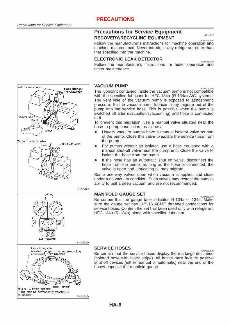
VACUUM PUMPNJHA0117S03
The lubricant contained inside the vacuum pump is not compatiblewith the specified lubricant for HFC-134a (R-134a) A/C systems.The vent side of the vacuum pump is exposed to atmosphericpressure. So the vacuum pump lubricant may migrate out of thepump into the service hose. This is possible when the pump isswitched off after evacuation (vacuuming) and hose is connectedto it.To prevent this migration, use a manual valve situated near thehose-to-pump connection, as follows.+ Usually vacuum pumps have a manual isolator valve as part
of the pump. Close this valve to isolate the service hose fromthe pump.
+ For pumps without an isolator, use a hose equipped with amanual shut-off valve near the pump end. Close the valve toisolate the hose from the pump.
+ If the hose has an automatic shut off valve, disconnect thehose from the pump: as long as the hose is connected, thevalve is open and lubricating oil may migrate.
Some one-way valves open when vacuum is applied and closeunder a no vacuum condition. Such valves may restrict the pump’sability to pull a deep vacuum and are not recommended.
SHA533D
MANIFOLD GAUGE SETNJHA0117S04
Be certain that the gauge face indicates R-134a or 134a. Makesure the gauge set has 1/2″-16 ACME threaded connections forservice hoses. Confirm the set has been used only with refrigerantHFC-134a (R-134a) along with specified lubricant.
RHA272D
SERVICE HOSESNJHA0117S05
Be certain that the service hoses display the markings described(colored hose with black stripe). All hoses must include positiveshut off devices (either manual or automatic) near the end of thehoses opposite the manifold gauge.
PRECAUTIONSPrecautions for Service Equipment
HA-6
RHA273D
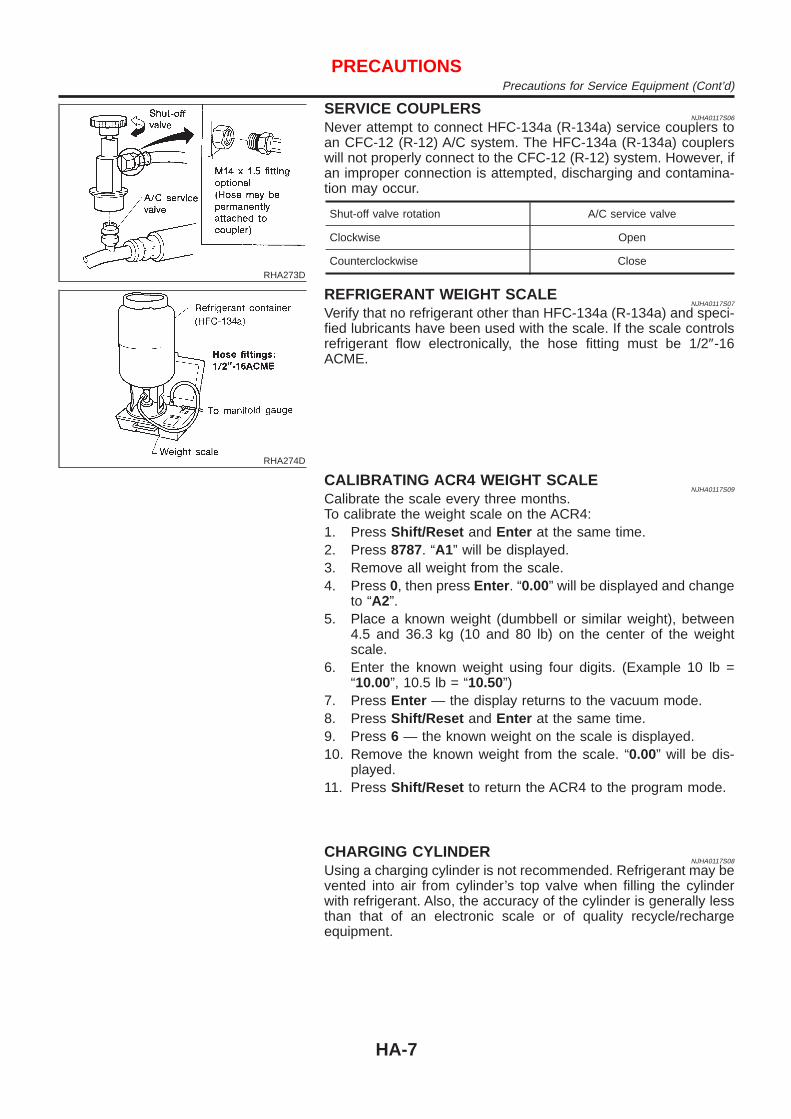
SERVICE COUPLERSNJHA0117S06
Never attempt to connect HFC-134a (R-134a) service couplers toan CFC-12 (R-12) A/C system. The HFC-134a (R-134a) couplerswill not properly connect to the CFC-12 (R-12) system. However, ifan improper connection is attempted, discharging and contamina-tion may occur.
Shut-off valve rotation A/C service valve
Clockwise Open
Counterclockwise Close
RHA274D
REFRIGERANT WEIGHT SCALENJHA0117S07
Verify that no refrigerant other than HFC-134a (R-134a) and speci-fied lubricants have been used with the scale. If the scale controlsrefrigerant flow electronically, the hose fitting must be 1/2″-16ACME.
CALIBRATING ACR4 WEIGHT SCALENJHA0117S09
Calibrate the scale every three months.To calibrate the weight scale on the ACR4:1. Press Shift/Reset and Enter at the same time.2. Press 8787. “A1” will be displayed.3. Remove all weight from the scale.4. Press 0, then press Enter . “0.00” will be displayed and change
to “A2”.5. Place a known weight (dumbbell or similar weight), between
4.5 and 36.3 kg (10 and 80 lb) on the center of the weightscale.
6. Enter the known weight using four digits. (Example 10 lb =“10.00”, 10.5 lb = “10.50”)
7. Press Enter — the display returns to the vacuum mode.8. Press Shift/Reset and Enter at the same time.9. Press 6 — the known weight on the scale is displayed.10. Remove the known weight from the scale. “0.00” will be dis-
played.11. Press Shift/Reset to return the ACR4 to the program mode.
CHARGING CYLINDERNJHA0117S08
Using a charging cylinder is not recommended. Refrigerant may bevented into air from cylinder’s top valve when filling the cylinderwith refrigerant. Also, the accuracy of the cylinder is generally lessthan that of an electronic scale or of quality recycle/rechargeequipment.
PRECAUTIONSPrecautions for Service Equipment (Cont’d)
HA-7
Wirin g Diagram s and Troubl e DiagnosisNJHA0118
When you read wiring diagrams, refer to the following:+ GI-11, “HOW TO READ WIRING DIAGRAMS”+ Sedan: EL-11 (QG), EL-19 (YD), Hatchback: EL-28, “Wiring
Diagram — POWER —”.When you perform trouble diagnosis, refer to the following:+ GI-32, “HOW TO FOLLOW TROUBLE DIAGNOSES”+ GI-21, “HOW TO PERFORM EFFICIENT DIAGNOSIS FOR
AN ELECTRICAL INCIDENT”
PRECAUTIONSWiring Diagrams and Trouble Diagnosis
HA-8

Special Service ToolsNJHA0119
DKV-11G COMPRESSORNJHA0119S01
Tool numberTool name
Description
KV99231260Clutch disc wrench
NT204
Removing shaft nut and clutch disc
KV99232340Clutch disc puller
NT206
Removing clutch disc
KV99234330Pulley installer
NT207
Installing pulley
KV99233130Pulley puller
NT208
Removing pulley
CSV613 COMPRESSORNJHA0119S02
Tool numberTool name
Description
KV99106100Clutch disc wrench
NT232
NT378
Removing center bolt
PREPARATIONSpecial Service Tools
HA-9

Tool numberTool name
Description
KV99232340Clutch disc puller
NT376
Removing clutch disc
KV99106200Pulley installer
NT235
Installing pulley
PREPARATIONSpecial Service Tools (Cont’d)
HA-10

HFC-134a (R-134a) Service Tools andEquipment
=NJHA0120
Never mix HFC-134a refrigerant and/or its specified lubricant with CFC-12 (R-12) refrigerant and/or its lubri-cant.Separate and non-interchangeable service equipment must be used for handling each type of refrigerant/lubricant.Refrigerant container fittings, service hose fittings and service equipment fittings (equipment which handlesrefrigerant and/or lubricant) are different between CFC-12 (R-12) and HFC-134a (R-134a). This is to avoidmixed use of the refrigerants/lubricant.Adapters that convert one size fitting to another must never be used: refrigerant/lubricant contamination willoccur and compressor failure will result.
Tool numberTool name
Description
HFC-134a (R-134a)refrigerant
NT196
Container color: Light blueContainer marking: HFC-134a (R-134a)Fitting size: Thread size+ Large container 1/2″-16 ACME
KLH00-PAGR0Nissan A/C System OilType RKLH00-PAGS0Nissan A/C System OilType S
NT197
Type: Poly alkylene glycol oil (PAG), type RApplication: HFC-134a (R-134a) vane rotary com-pressors (Nissan only)Type SApplication: HFC-134a (R-134a) swash plate com-pressors (Nissan only)Lubricity: 40 m! (1.4 Imp fl oz)
Recovery/RecyclingRecharging equipment(ACR4)
NT195
Function: Refrigerant Recovery and Recycling andRecharging
Electrical leak detector
NT198
Power supply:+ DC 12V (Cigarette lighter)
Manifold gauge set (withhoses and couplers)
NT199
Identification:+ The gauge face indicates R-134a.Fitting size: Thread size+ 1/2″-16 ACME
PREPARATIONHFC-134a (R-134a) Service Tools and Equipment
HA-11

Tool numberTool name
Description
Service hoses+ High side hose+ Low side hose+ Utility hose
NT201
Hose color:+ Low hose: Blue with black stripe+ High hose: Red with black stripe+ Utility hose: Yellow with black stripe or green
with black stripeHose fitting to gauge:+ 1/2″-16 ACME
Service couplers+ High side coupler+ Low side coupler
NT202
Hose fitting to service hose:+ M14 x 1.5 fitting is optional or permanently
attached.
Refrigerant weight scale
NT200
For measuring of refrigerantFitting size: Thread size+ 1/2″-16 ACME
Vacuum pump(Including the isolatorvalve)
NT203
Capacity:+ Air displacement: 4 CFM+ Micron rating: 20 microns+ Oil capacity: 482 g (17 oz)Fitting size: Thread size+ 1/2″-16 ACME
PREPARATIONHFC-134a (R-134a) Service Tools and Equipment (Cont’d)
HA-12

Refrigeration SystemREFRIGERATION CYCLE
NJHA0121
Refrigerant FlowNJHA0121S01
The refrigerant flows in the standard pattern, that is, through the compressor, the condenser, the liquid tank,through the evaporator, and back to the compressor. The refrigerant evaporation through the evaporator coilis controlled by an externally equalized expansion valve, located inside the heater & cooling unit.
Freeze ProtectionNJHA0121S02
The compressor cycles go on and off to maintain the evaporator temperature within a specified range. Whenthe evaporator coil temperature falls below a specified point, the thermo control amplifier interrupts the com-pressor operation. When the evaporator coil temperature rises above the specification, the thermo controlamplifier allows compressor operation.
Refrigerant System ProtectionNJHA0121S03
Refrigerant Pressure SensorNJHA0121S0303
The refrigerant system is protected against excessively high or low pressures by the refrigerant pressuresensor, located on the liquid tank. If the system pressure rises above, or falls below the specifications, therefrigerant pressure sensor detects the pressure inside the refrigerant line and sends the voltage signal to theECM. ECM makes the A/C relay go OFF and stops the compressor when pressure on the high pressure sidedetected by refrigerant pressure sensor is over about 2,746 kPa (27.5 bar, 28 kg/cm2, 398 psi) or below about137 kPa (1.37 bar, 1.4 kg/cm2, 20 psi).Dual-pressure Switch
NJHA0121S0304
The refrigerant system is protected against excessively high or low pressures by the dual-pressure switch,located on the liquid tank. If the pressure falls out of specifications, the switch opens to interrupt compressoroperation.Pressure Relief Valve
NJHA0121S0302
The refrigerant system is also protected by a pressure relief valve, located in the rear head of the compres-sor. When the pressure of refrigerant in the system increases to an abnormal level [more than 3,727 kPa (37.3bar, 38 kg/cm2, 540 psi)], the release port on the pressure relief valve automatically opens and releasesrefrigerant into the atmosphere.
RHA682H
DESCRIPTIONRefrigeration System
HA-13
CSV613 Variable Displacement CompressorGENERAL INFORMATION
NJHA0206
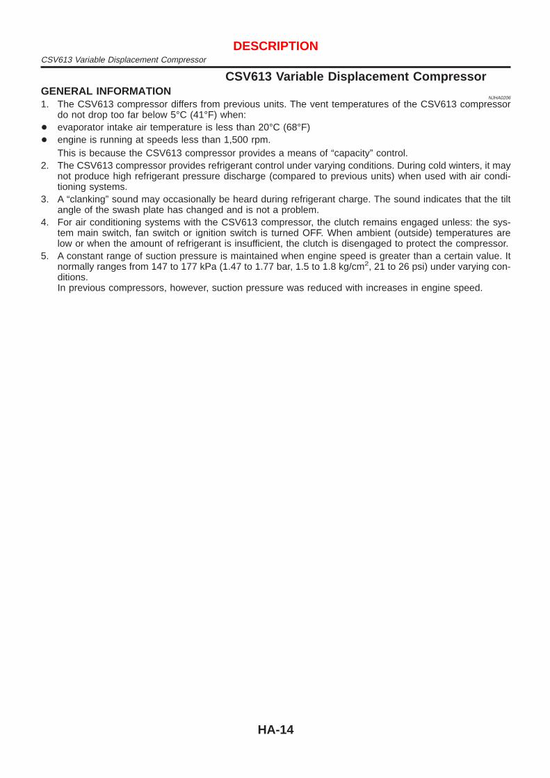
1. The CSV613 compressor differs from previous units. The vent temperatures of the CSV613 compressordo not drop too far below 5°C (41°F) when:
+ evaporator intake air temperature is less than 20°C (68°F)+ engine is running at speeds less than 1,500 rpm.
This is because the CSV613 compressor provides a means of “capacity” control.2. The CSV613 compressor provides refrigerant control under varying conditions. During cold winters, it may
not produce high refrigerant pressure discharge (compared to previous units) when used with air condi-tioning systems.
3. A “clanking” sound may occasionally be heard during refrigerant charge. The sound indicates that the tiltangle of the swash plate has changed and is not a problem.
4. For air conditioning systems with the CSV613 compressor, the clutch remains engaged unless: the sys-tem main switch, fan switch or ignition switch is turned OFF. When ambient (outside) temperatures arelow or when the amount of refrigerant is insufficient, the clutch is disengaged to protect the compressor.
5. A constant range of suction pressure is maintained when engine speed is greater than a certain value. Itnormally ranges from 147 to 177 kPa (1.47 to 1.77 bar, 1.5 to 1.8 kg/cm2, 21 to 26 psi) under varying con-ditions.In previous compressors, however, suction pressure was reduced with increases in engine speed.
DESCRIPTIONCSV613 Variable Displacement Compressor
HA-14

DESCRIPTION=NJHA0207
GeneralNJHA0207S01
The variable compressor is basically a swash plate type that changes piston stroke in response to the requiredcooling capacity.The tilt of the swash plate allows the piston’s stroke to change so that refrigerant discharge can be continu-ously changed from 6.0 to 125 cm3 (0.366 to 7.628 cu in).
RHA854HA
DESCRIPTIONCSV613 Variable Displacement Compressor (Cont’d)
HA-15

Operation=NJHA0207S02
1. Operation Control ValveNJHA0207S0201
Operation control valve is located in the suction port (low-pressure) side, and opens or closes in response tochanges in refrigerant suction pressure.Operation of the valve controls the internal pressure of the crankcase.The angle of the swash plate is controlled between the crankcase’s internal pressure and the piston cylinderpressure.2. Maximum Cooling
NJHA0207S0202
Refrigerant pressure on the low-pressure side increases with an increase in heat loads.When this occurs, the control valve’s bellows compress to open the low-pressure side valve and close thehigh-pressure side valve.This causes the following pressure changes:+ the crankcase’s internal pressure to equal the pressure on the low-pressure side;+ the cylinder’s internal pressure to be greater than the crankcase’s internal pressure.Under this condition, the swash plate is set to the maximum stroke position.
RHA473C
DESCRIPTIONCSV613 Variable Displacement Compressor (Cont’d)
HA-16
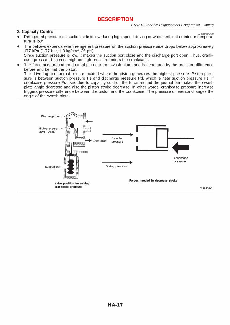
3. Capacity Control=NJHA0207S0203
+ Refrigerant pressure on suction side is low during high speed driving or when ambient or interior tempera-ture is low.
+ The bellows expands when refrigerant pressure on the suction pressure side drops below approximately177 kPa (1.77 bar, 1.8 kg/cm2, 26 psi).Since suction pressure is low, it makes the suction port close and the discharge port open. Thus, crank-case pressure becomes high as high pressure enters the crankcase.
+ The force acts around the journal pin near the swash plate, and is generated by the pressure differencebefore and behind the piston.The drive lug and journal pin are located where the piston generates the highest pressure. Piston pres-sure is between suction pressure Ps and discharge pressure Pd, which is near suction pressure Ps. Ifcrankcase pressure Pc rises due to capacity control, the force around the journal pin makes the swashplate angle decrease and also the piston stroke decrease. In other words, crankcase pressure increasetriggers pressure difference between the piston and the crankcase. The pressure difference changes theangle of the swash plate.
RHA474C
DESCRIPTIONCSV613 Variable Displacement Compressor (Cont’d)
HA-17

Component LayoutNJHA0122
RHA589H
DESCRIPTIONComponent Layout
HA-18

Control OperationNJHA0123
RHA747H
FAN CONTROL SWITCHNJHA0123S01
This switch turns the fan ON and OFF, and controls fan speed.
MODE CONTROL KNOBNJHA0123S02
This knob controls the outlet air flow.
TEMPERATURE CONTROL KNOBNJHA0123S03
This knob allows you to adjust the temperature of the discharge air.
REAR WINDOW DEFOGGER SWITCHNJHA0123S07
When illumination is ON, rear window is defogged.
AIR CONDITIONER (A/C) SWITCHNJHA0123S05
The air conditioner switch controls the A/C system. When the switch is depressed with the fan ON, the com-pressor will turn ON. The indicator lamp will also light.The air conditioner cooling function operates only when the engine is running.
RECIRCULATION (REC) SWITCHNJHA0123S08
Recirculation (REC) position: Interior air is recirculated inside the vehicle. (The indicator lamp will light.)Fresh (FRE) position: Outlet air is drawn into the passenger compartment. (The indicator lamp will not light.)
DESCRIPTIONControl Operation
HA-19

Discharge Air FlowNJHA0124
RHA748H
DESCRIPTIONDischarge Air Flow
HA-20

System DescriptionNJHA0125
SWITCHES AND THEIR CONTROL FUNCTIONSNJHA0125S01
Knob/SwitchKnob/Switch position
CompressorA/C VENT B/L FOOT D/F DEF REC FRE
A/C j ON*1
Mode
j —
j —
j —
j —
j —
Intake
j —
j —
*1: Compressor is operated by ECM.
MAX HOT DOOR FUNCTION FOR SCANDINAVIA ANDCOLD SPEC MODELS ONLY
NJHA0125S02
RHA812H
DESCRIPTIONSystem Description
HA-21
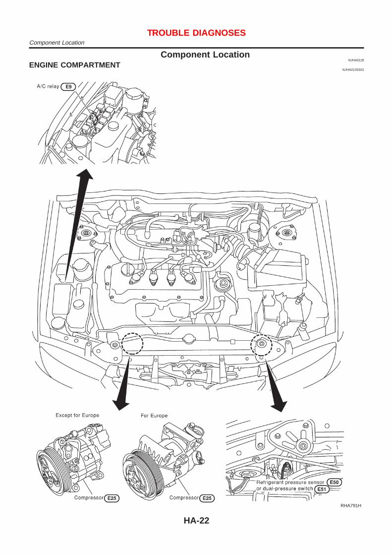
Component LocationNJHA0126
ENGINE COMPARTMENTNJHA0126S01
RHA791H
TROUBLE DIAGNOSESComponent Location
HA-22

PASSENGER COMPARTMENTNJHA0126S02
RHA792H
TROUBLE DIAGNOSESComponent Location (Cont’d)
HA-23

Wiring Diagram — HeaterNJHA0202
4-DOOR SEDANNJHA0202S02
HHA211
TROUBLE DIAGNOSESWiring Diagram — Heater
HA-24

HATCHBACKNJHA0202S03
NHA476
TROUBLE DIAGNOSESWiring Diagram — Heater (Cont’d)
HA-25

Circuit
Diagram
—A
irC
onditionerN
JHA
0127
HH
A240
TRO
UB
LED
IAG
NO
SE
SC
ircuitD
iagram—
Air
Conditioner
HA
-26

Wiring Diagram — A/C, M —NJHA0128
MODELS WITH QG ENGINENJHA0128S03
NHA477
TROUBLE DIAGNOSESWiring Diagram — A/C, M —
HA-27

NHA478
TROUBLE DIAGNOSESWiring Diagram — A/C, M — (Cont’d)
HA-28

NHA479
TROUBLE DIAGNOSESWiring Diagram — A/C, M — (Cont’d)
HA-29
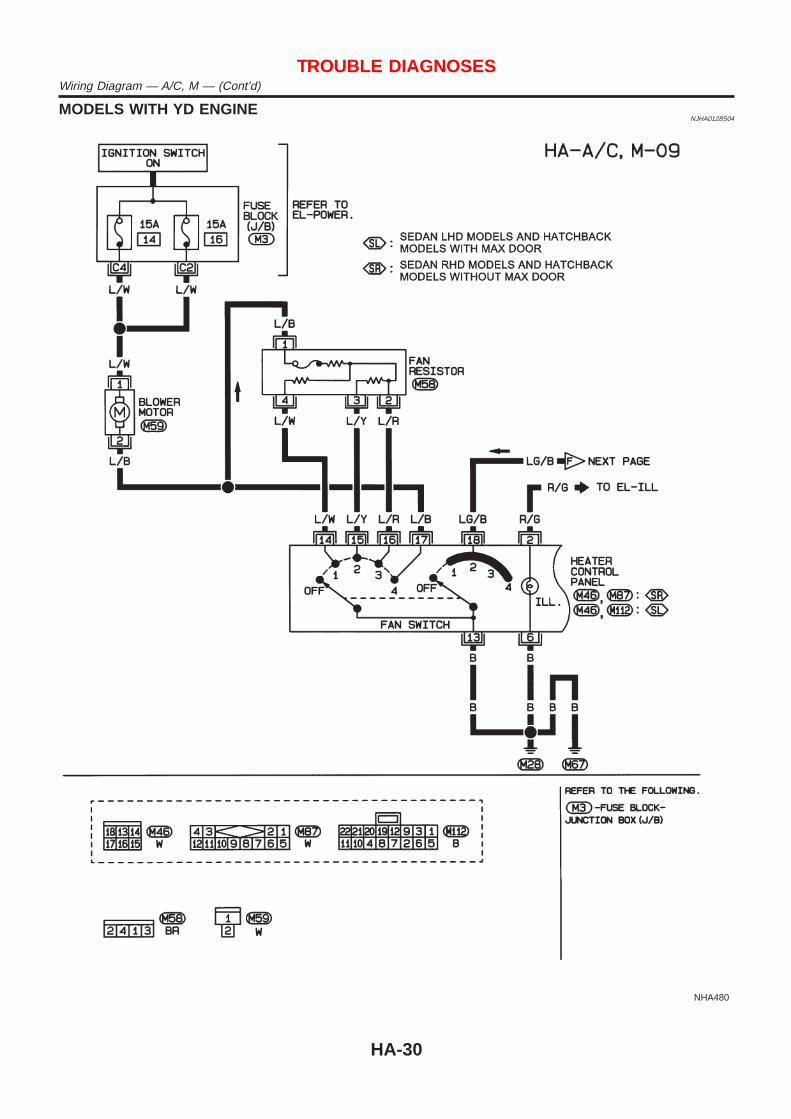
MODELS WITH YD ENGINENJHA0128S04
NHA480
TROUBLE DIAGNOSESWiring Diagram — A/C, M — (Cont’d)
HA-30

NHA481
TROUBLE DIAGNOSESWiring Diagram — A/C, M — (Cont’d)
HA-31

NHA482
TROUBLE DIAGNOSESWiring Diagram — A/C, M — (Cont’d)
HA-32

How to Perform Trouble Diagnoses for Quickand Accurate Repair
NJHA0129
WORK FLOWNJHA0129S01
SHA900E
*1: HA-34
SYMPTOM TABLENJHA0129S02
Symptom Reference page
+ Intake door does not change. + Go to Trouble Diagnosis Procedure for Intake Door. HA-36
+ Air outlet does not change. + Go to Trouble Diagnosis Procedure for mode door. HA-40
+ Air mix door does not change. + Go to Trouble Diagnosis Procedure for Air mix door. HA-42
+ Max hot door does not change. + Go to Trouble Diagnosis Procedure for Max Hot Door. HA-44
+ Blower motor does not rotate at all. + Go to Trouble Diagnosis Procedure for Blower Motor. HA-48
+ Magnet clutch does not engage when A/C switch andfan switch are ON.
+ Go to Trouble Diagnosis Procedure for Magnet Clutch. HA-55
+ Insufficient cooling. + Go to Trouble Diagnosis Procedure for Insufficient cool-ing.
HA-68
+ Insufficient heating. + Go to Trouble Diagnosis Procedure for Insufficientheating.
HA-76
+ Noise + Go to Trouble Diagnosis Procedure for Noise. HA-77
TROUBLE DIAGNOSESHow to Perform Trouble Diagnoses for Quick and Accurate Repair
HA-33

Operational Check=NJHA0130
The purpose of the operational check is to confirm that the systemoperates properly.
CONDITIONS:NJHA0130S01
+ Engine running and at normal operating temperature.
NHA374
PROCEDURE:NJHA0130S02
1. Check BlowerNJHA0130S0201
1. Turn fan switch to 1-speed.Blower should operate on 1-speed.
2. Then turn fan switch to 2-speed, and continue checking blowerspeed until all speeds are checked.
3. Leave blower on 4-speed.If NG, go to trouble diagnosis procedure for blower motor (HA-48).If OK, continue with next check.
NHA375
2. Check Discharge AirNJHA0130S0202
1. Turn mode control knob to each position.
RHA654FK
2. Confirm that discharge air comes out according to the air dis-tribution table at left.
Refer to “Discharge Air Flow”, HA-20.If NG, go to trouble diagnosis procedure for mode door motor(HA-40).If OK, continue with next check.
TROUBLE DIAGNOSESOperational Check
HA-34

NHA377
3. Check RecirculationNJHA0130S0203
1. Press the Recirculation (REC) switch. Recirculation indicatorshould illuminate.
2. Listen for intake door position change.If NG, go to trouble diagnosis procedure for intake door (HA-36).If OK, continue with next check.
NHA378
4. Check Temperature DecreaseNJHA0130S0204
1. Turn the temperature control knob to full cold.2. Check for cold air at discharge air outlets.If NG, go to trouble diagnosis procedure for insufficient cooling(HA-68).If OK, continue with next check.
NHA379
5. Check Temperature IncreaseNJHA0130S0205
1. Turn the temperature control knob to full hot.2. Check for hot air at discharge air outlets.If NG, go to trouble diagnosis procedure for insufficient heating(HA-76).
NHA380
6. Check Air Conditioner SwitchNJHA0130S0206
Turn the fan control switch to the desired (1 to 4 speed) positionand push the A/C switch to turn ON the air conditioner.The indicator lamp should come on when air conditioner is ON.If NG, go to trouble diagnosis procedure for magnet clutch (HA-55).
TROUBLE DIAGNOSESOperational Check (Cont’d)
HA-35

Intake DoorTROUBLE DIAGNOSIS PROCEDURE FOR INTAKE DOOR
=NJHA0133
SYMPTOM:+ Intake door does not change.INSPECTION FLOW
NHA381
*1: HA-34 *2: HA-33 *3: HA-37
TROUBLE DIAGNOSESIntake Door
HA-36

RHA623H
COMPONENT DESCRIPTIONNJHA0209
Intake Door MotorNJHA0209S01
The intake door motor is attached to the intake unit. It rotates sothat air is drawn from inlets set by the heater control panel. Motorrotation is conveyed to a lever which activates the intake door.
DIAGNOSTIC PROCEDURE FOR INTAKE DOORMOTOR CIRCUIT
NJHA0210
1 CHECK POWER SUPPLY FOR HEATER CONTROL PANEL
Do approx. 12 volts exist between heater control panel harness terminal No. 1 and body ground?
NHA483
Yes or No
Yes © GO TO 2.
No © Check 10A (No. 15) fuse at fuse block. Refer to Sedan: EL-11 (QG), EL-19 (YD), Hatch-back: EL-28, “Wiring Diagram — POWER —”.
2 CHECK RECIRCULATION (REC) SWITCH
Refer to HA-39.
OK or NG
OK © GO TO 3.
NG © Replace recirculation (REC) switch.
TROUBLE DIAGNOSESIntake Door (Cont’d)
HA-37

3 CHECK GROUND CIRCUIT FOR RECIRCULATION (REC) SWITCH
Check circuit continuity between heater control panel harness terminal No. 5 and body ground.
NHA484
Continuity should exist.If OK, check harness for short.
OK or NG
OK © GO TO 4.
Ng © Repair harness or connector.
4 CHECK POWER SUPPLY FOR INTAKE DOOR MOTOR
Do approx. 12 volts exist between intake door motor harness terminal No. 1, 2 and body ground?
RHA758H
Yes or No
Yes © Replace intake door motor.
No © GO TO 5.
TROUBLE DIAGNOSESIntake Door (Cont’d)
HA-38

5 CHECK CIRCUIT CONTINUITY BETWEEN HEATER CONTROL PANEL AND INTAKE DOOR MOTOR
Check circuit continuity between heater control panel harness terminal No. 10 (11) and intake door motor harness terminalNo. 2 (1)
NHA485
Continuity should exist.If OK, check harness for short.
OK or NG
OK © Replace heater control panel.
NG © Repair harness or connector.
NHA486
ELECTRICAL COMPONENT INSPECTIONNJHA0216
Recirculation (REC) SwitchNJHA0216S01
Check continuity between terminals.
Terminals REC switch Continuity
1 - 5ON Yes
OFF No
RHA926H
Intake Door MotorNJHA0216S02
Supply 12V direct current to intake door motor terminal No. 1 and2.
12V direct current supply terminalsIntake door position
+ −
1 2 FRE
2 1 REC
TROUBLE DIAGNOSESIntake Door (Cont’d)
HA-39

Mode DoorTROUBLE DIAGNOSIS PROCEDURE FOR MODE DOOR
=NJHA0137
SYMPTOM:+ Air outlet does not change.INSPECTION FLOW
NHA382
*1: HA-20*2: HA-34
*3: HA-41 *4: HA-33
TROUBLE DIAGNOSESMode Door
HA-40

RHA695H
RHA745H
CONTROL LINKAGE ADJUSTMENTNJHA0139
Mode DoorNJHA0139S01
1. Turn the mode control knob to VENT position.2. Move side link by hand and hold mode door in VENT position.3. Pull on the cable cover in the direction of the arrow, then clamp
it.After positioning control cable, check that it operatesproperly.
TROUBLE DIAGNOSESMode Door (Cont’d)
HA-41

Air Mix DoorTROUBLE DIAGNOSIS PROCEDURE FOR AIR MIX DOOR
=NJHA0140
SYMPTOM:+ Air mix door does not change.INSPECTION FLOW
NHA383
*1: HA-43*2: HA-34
*3: HA-34 *4: HA-33
TROUBLE DIAGNOSESAir Mix Door
HA-42

RHA697H
RHA746H
CONTROL LINKAGE ADJUSTMENTNJHA0143
Air Mix DoorNJHA0143S01
1. Turn the temperature control knob to full hot position.2. Move air mix door lever by hand and hold it at the full hot
position.3. Pull on the cable cover in the direction of the arrow, then clamp
it.After positioning control cable, check that it operatesproperly.
TROUBLE DIAGNOSESAir Mix Door (Cont’d)
HA-43

Max Hot Door (For Scandinavia and Cold SpecModels)
TROUBLE DIAGNOSIS FOR MAX HOT DOOR=NJHA0223
SYMPTOM:+ Max hot door does not change.INSPECTION FLOW
RHA915H
*1: HA-45*2: HA-34
*3: HA-34 *4: HA-33
TROUBLE DIAGNOSESMax Hot Door (For Scandinavia and Cold Spec Models)
HA-44

RHA796H
COMPONENT DESCRIPTIONNJHA0217
Max Hot Door MotorNJHA0217S01
The max hot door motor is attached to the heater & cooling unit.
Mode door positionTemperature control
positionMax hot door position
FOOT, D/FFull hot OPEN
All except full hot SHUT
VENT, B/L, DEFFull hot SHUT
All except full hot SHUT
DIAGNOSTIC PROCEDURE FOR MAX HOT DOOR MOTOR CIRCUITNJHA0218
1 CHECK SIGNAL FOR OPEN OPERATION
1. Turn ignition switch to ON position.2. Set temperature dial to “FULL COLD” position, and mode control dial to the “DEF ( )”, “VENT ( )” or “BI-LEVEL
( )” position.3. Set temperature dial to “FULL HOT” position, and mode control dial to the “FOOT ( )” or “FOOT/DEF ( )” posi-
tion. At this time, does an approx. 12 volts exist between the max hot door motor harness connector terminal 7 and thebody ground until the max hot door is fully opened?
RHA920HA
Yes or No
Yes © GO TO 2.[If max hot door motor does not operate even if approx. 12 volts exist, then replace maxhot door motor. (Before replacing the motor, check for smooth operation of the door.)]
No © GO TO 3.
TROUBLE DIAGNOSESMax Hot Door (For Scandinavia and Cold Spec Models) (Cont’d)
HA-45

2 CHECK SIGNAL FOR CLOSE OPERATION
1. Turn ignition switch to ON position.2. Set temperature dial to “FULL HOT” position, and mode control dial to the “FOOT ( )” or “FOOT/DEF ( )” position3. Set temperature dial to “FULL COLD” position, and the mode control dial to the “DEF ( )”, “VENT ( )” or “BI-
LEVEL ( )” position. At this time, does an approx. 12 volts exist between the max hot door motor harness connectorterminal 6 and the body ground until the max hot door is fully closed?
RHA921HA
Yes or No
Yes © INSPECTION END. (Max hot door motor is OK.)[If max hot door motor does not operate even if approx. 12 volts exist, then replace themax hot door motor. (Before replacing the motor, check for smooth operation of thedoor.)]
No © GO TO 3.
3 CHECK SIGNAL CIRCUIT
1. Disconnect heater control panel harness connector and max hot door motor harness connector.2. Check for continuity between heater control panel harness connector terminal 19 and max hot door motor harness con-
nector terminal 6, heater control panel harness connector terminal 21 and max hot door motor harness connector termi-nal 7.
RHA922HA
Continuity should exist.If OK, check harness for short.
Yes or No
Yes © GO TO 4.
No © Repair harness or connector.If harness and connector are OK, replace heater control panel.
TROUBLE DIAGNOSESMax Hot Door (For Scandinavia and Cold Spec Models) (Cont’d)
HA-46

4 CHECK SIGNAL FOR POSITION SWITCH
1. Connect the heater control panel harness connector and the max hot door motor harness connector.2. Check the voltage between the heater control panel harness connector terminal 20 and body ground, heater control
panel harness connector terminal 22 and body ground as shown in the condition below.
RHA923HA
OK or NG
OK © Position switch (max hot door motor) is OK.
NG © GO TO 5.
5 CHECK POSITION SWITCH (BUILT-IN MAX HOT DOOR MOTOR)
Check continuity between max hot door motor terminals 1 and 5, 4 and 5 as shown in the condition below.
RHA916HA
OK or NG
OK © INSPECTION END. (Position switch is OK.)
NG © Check harness for open or short between:+ Heater control panel harness connector terminals 20, 22 and max hot door harness
connector terminals 1, 4.+ Max hot door motor harness connector terminal 5 and body ground.
RHA855H
CONTROL LINKAGE ADJUSTMENTNJHA0219
Max Hot DoorNJHA0219S01
1. Install max hot door motor on heater unit. Ensure that the maxhot door lever is fitted into the slit portion of max hot door link.
2. Connect the max hot door motor harness connector.3. Turn ignition switch to “ON” position.4. Turn the temperature control knob to full hot.5. Check that max hot door operates properly when the mode
control knob is turned to FOOT or D/F, and other positions.
TROUBLE DIAGNOSESMax Hot Door (For Scandinavia and Cold Spec Models) (Cont’d)
HA-47

Blower MotorTROUBLE DIAGNOSIS PROCEDURE FOR BLOWER MOTOR
=NJHA0145
SYMPTOM:+ Blower motor does not rotate at all.INSPECTION FLOW
NHA385
*1: HA-49*2: HA-34
*3: HA-33 *4: HA-34
TROUBLE DIAGNOSESBlower Motor
HA-48
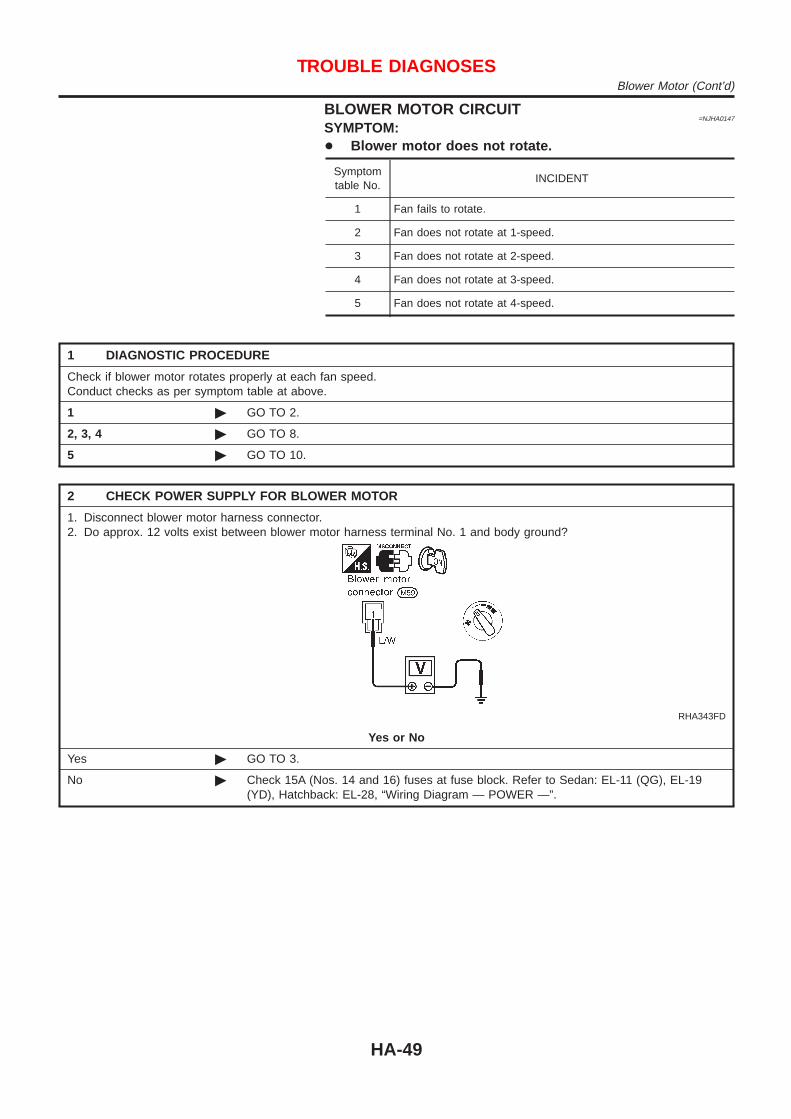
BLOWER MOTOR CIRCUIT=NJHA0147
SYMPTOM:+ Blower motor does not rotate.
Symptomtable No.
INCIDENT
1 Fan fails to rotate.
2 Fan does not rotate at 1-speed.
3 Fan does not rotate at 2-speed.
4 Fan does not rotate at 3-speed.
5 Fan does not rotate at 4-speed.
1 DIAGNOSTIC PROCEDURE
Check if blower motor rotates properly at each fan speed.Conduct checks as per symptom table at above.
1 © GO TO 2.
2, 3, 4 © GO TO 8.
5 © GO TO 10.
2 CHECK POWER SUPPLY FOR BLOWER MOTOR
1. Disconnect blower motor harness connector.2. Do approx. 12 volts exist between blower motor harness terminal No. 1 and body ground?
RHA343FD
Yes or No
Yes © GO TO 3.
No © Check 15A (Nos. 14 and 16) fuses at fuse block. Refer to Sedan: EL-11 (QG), EL-19(YD), Hatchback: EL-28, “Wiring Diagram — POWER —”.
TROUBLE DIAGNOSESBlower Motor (Cont’d)
HA-49

3 CHECK CIRCUIT CONTINUITY FOR BLOWER MOTOR
1. Turn fan control knob to any position except OFF.2. Check circuit continuity between blower motor harness terminal No. 2 and body ground.
RHA344FD
Continuity should exist.If OK, check harness for short.
OK or NG
OK © GO TO 4.
NG © Reconnect blower motor harness connector. GO TO 5.
4 CHECK BLOWER MOTOR
(Refer to Electrical Components Inspection.)(HA-54)
OK or NG
OK © INSPECTION END
NG © Replace blower motor.
5 CHECK BLOWER MOTOR CIRCUIT BETWEEN BLOWER MOTOR AND RESISTOR
Do approx. 12 volts exist between fan resistor harness terminal No. 1 and body ground?
RHA699HA
Yes or No
Yes © Disconnect fan switch harness connector. GO TO 7.
No © Disconnect blower motor and resistor harness connectors. GO TO 6.
TROUBLE DIAGNOSESBlower Motor (Cont’d)
HA-50

6 CHECK CIRCUIT CONTINUITY BETWEEN BLOWER MOTOR AND RESISTOR
Check circuit continuity between blower motor harness terminal No. 2 and fan resistor harness terminal No. 1.
RHA700HA
Continuity should exist.If OK, check harness for short.
OK or NG
OK © Poor contact between the resistor and blower motor connector.
NG © Repair harness or connector.
7 CHECK GROUND CIRCUIT FOR HEATER CONTROL PANEL
Check circuit continuity between fan switch harness terminal No. 9 or 13 and body ground.
RHA849H
Continuity should exist.If OK, check harness for short.
OK or NG
OK © GO TO 8.
NG © Repair harness or connector.
8 CHECK RESISTOR AFTER DISCONNECTING IT
(Refer to Electrical Components Inspection.)(HA-54)
OK or NG
OK © GO TO 9.
NG © Replace resistor.
9 CHECK RESISTOR HARNESS CONNECTOR
Reconnect resistor harness connector.
OK or NG
1 © GO TO 12.
2, 3, 4 © GO TO 10.
TROUBLE DIAGNOSESBlower Motor (Cont’d)
HA-51

10 CHECK FAN SWITCH CIRCUIT
Do approx. 12 volts exist between each fan switch harness terminal and body ground?
RHA850H
Yes or No
Yes © GO TO 13.
No © GO TO 11.
11 CHECK CIRCUIT CONTINUITY BETWEEN HEATER CONTROL PANEL AND RESISTOR
Check circuit continuity between heater control panel harness terminals and fan resistor harness terminals.
RHA851H
Continuity should exist.If OK, check harness for short.
OK or NG
OK © GO TO 12.
NG © Repair harness or connector.
TROUBLE DIAGNOSESBlower Motor (Cont’d)
HA-52

12 CHECK CIRCUIT CONTINUITY BETWEEN HEATER CONTROL PANEL AND BLOWER MOTOR
Check circuit continuity between heater control panel harness terminal No. 13 or 17 and blower motor harness terminalNo. 2.
RHA852H
Continuity should exist.If OK, check harness for short.
OK or NG
OK © GO TO 13.
NG © Repair harness or connector.
13 CHECK FAN SWITCH AFTER DISCONNECTING IT
(Refer to Electrical Components Inspection.)(HA-54)
OK or NG
OK © INSPECTION END
NG © Replace fan switch.
TROUBLE DIAGNOSESBlower Motor (Cont’d)
HA-53

NHA386
ELECTRICAL COMPONENTS INSPECTION=NJHA0146
Fan SwitchNJHA0146S01
Check continuity between terminals at each switch position.
KNOB POSITION Continuity between terminals
OFF No continuity
1 13 — 14 — 18
2 13 — 15 — 18
3 13 — 16 — 18
4 13 — 17 — 18
Blower MotorNJHA0146S02
Confirm smooth rotation of the blower motor.+ Ensure that there are no foreign particles inside the intake unit.
RHA706H
Blower ResistorNJHA0146S03
Check resistance between terminals.
Terminal No. Resistance
(+) (−)LHD models for
EuropeExcept LHD mod-
els for Europe
4
1
Approx. 2.4 - 2.8Ω
3Approx. 0.58 -
0.7Ω Approx. 1.2 - 1.4Ω
2Approx. 0.22 -
0.26ΩApprox. 0.43 -
0.51Ω
TROUBLE DIAGNOSESBlower Motor (Cont’d)
HA-54

Magnet ClutchTROUBLE DIAGNOSIS PROCEDURE FOR MAGNET CLUTCH
=NJHA0155
SYMPTOM:+ Magnet clutch does not operate when A/C switch and fan switch are ON.INSPECTION FLOW
NHA387
*1: HA-93*2: HA-56
*3: HA-34*4: HA-33
*5: EM-16 (QG),EM-85 (YD)
TROUBLE DIAGNOSESMagnet Clutch
HA-55

MAGNET CLUTCH CIRCUIT (FOR QG ENGINE)=NJHA0156
SYMPTOM:+ Magnet clutch does not engage when A/C switch and fan
switch are ON.
1 CHECK POWER SUPPLY FOR COMPRESSOR
Disconnect compressor harness connector.Do approx. 12 volts exist between compressor harness terminal No. 1 and body ground?
RHA794H
Yes or No
Yes © GO TO 2.
No © Disconnect A/C relay. GO TO 3.
2 CHECK MAGNET CLUTCH COIL
OK or NG
NG © Replace magnet clutch. Refer to HA-85.
3 CHECK CIRCUIT CONTINUITY BETWEEN A/C RELAY AND COMPRESSOR HARNESS
Check circuit continuity between A/C relay harness terminal No. 3 and compressor harness terminal No. 1.
RHA634H
Continuity should exist.If OK, check harness for short.
OK or NG
OK © GO TO 4.
NG © Repair harness or connector.
TROUBLE DIAGNOSESMagnet Clutch (Cont’d)
HA-56

4 CHECK POWER SUPPLY FOR A/C RELAY
Disconnect A/C relay.Do approx. 12 volts exist between A/C relay harness terminal Nos. 1, 5 and body ground?
RHA635H
Yes or No
Yes © GO TO 5.
No © Check power supply circuit and 10A (No. 15) fuse at fuse block. Refer to Sedan: EL-11,Hatchback: EL-28, “Wiring Diagram — POWER —”.
5 CHECK A/C RELAY AFTER DISCONNECTING IT
Refer to HA-66.
OK or NG
OK © Reconnect A/C relay. GO TO 6.
NG © Replace A/C relay.
6 CHECK COIL SIDE CIRCUIT OF A/C RELAY
Do approx. 12 volts exist between ECM harness terminal No. 16 or 23 and body ground?
RHA764H
Yes or No
Yes © GO TO 8.
No © Disconnect A/C relay. Disconnect ECM harness connector. GO TO 7.
TROUBLE DIAGNOSESMagnet Clutch (Cont’d)
HA-57

7 CHECK CIRCUIT CONTINUITY BETWEEN A/C RELAY AND ECM HARNESS
Check circuit continuity between A/C relay harness terminal No. 2 and ECM harness terminal No. 16 or 23.
RHA765H
Continuity should exist.If OK, check harness for short.
OK or NG
OK © Check ECM. Refer to EC-164 (QG), “ECM Terminals and Reference Value”.
NG © Repair harness or connector.
8 CHECK VOLTAGE FOR ECM
Do approx. 12 volts exist between ECM harness terminal No. 68 or 51 and body ground?
RHA766H
Yes or No
Yes © GO TO 9.
No © Check ECM. Refer to EC-164 (QG), EC-659 (YD), “ECM Terminals and ReferenceValue”.
9 CHECK REFRIGERANT PRESSURE SENSOR
Refer to HA-67.
OK or NG
OK © GO TO 10.
NG © Replace refrigerant pressure sensor.
10 CHECK A/C SWITCH
Refer to HA-67.
OK or NG
OK © GO TO 11.
NG © Replace heater control panel.
TROUBLE DIAGNOSESMagnet Clutch (Cont’d)
HA-58

11 CHECK POWER SUPPLY FOR HEATER CONTROL PANEL (A/C SWITCH)
Do approx. 12 volts exist between heater control panel harness terminal No. 7 and body ground?
NHA487
Yes or No
Yes © GO TO 13.
No © GO TO 12.
12 CHECK CIRCUIT CONTINUITY BETWEEN HEATER CONTROL PANEL AND ECM
Check circuit continuity between heater control panel harness terminal No. 7 and ECM harness terminal No. 44.
NHA488
Continuity should exist.If OK, check harness for short.
OK or NG
OK © Check ECM. Refer to EC-164 (QG), EC-659 (YD), “ECM Terminals and ReferenceValue”.
NG © Repair harness or connector.
TROUBLE DIAGNOSESMagnet Clutch (Cont’d)
HA-59

13 CHECK HEATER CONTROL PANEL CIRCUIT
Check circuit continuity between heater control panel harness terminal No. 8 and 18.
NHA489
Continuity should exist.If OK, check harness for short.
OK or NG
OK © GO TO 14.
NG © Repair harness or connector.
14 CHECK CIRCUIT CONTINUITY BETWEEN ECM AND HEATER CONTROL PANEL
Check circuit continuity between ECM harness terminal No. 68 or 51 and heater control panel harness terminal No. 14 or18.
RHA770H
Continuity should exist.If OK, check harness for short.
OK or NG
OK © GO TO 15.
NG © Repair harness or connector.
15 CHECK FAN SWITCH
Refer to HA-54.
Yes or No
Yes © GO TO 16.
No © Replace heater control panel.
TROUBLE DIAGNOSESMagnet Clutch (Cont’d)
HA-60

16 CHECK BODY GROUND CIRCUIT
Check circuit continuity between heater control panel harness terminal No. 9 or 13 and body ground.
RHA771H
Continuity should exist.If OK, check harness for short.
OK or NG
OK © INSPECTION END
NG © Repair harness or connector.
MAGNET CLUTCH CIRCUIT (FOR YD ENGINE)NJHA0203
SYMPTOM:+ Magnet clutch does not engage when A/C switch and fan
switch are ON.
1 CHECK POWER SUPPLY FOR COMPRESSOR
Disconnect compressor harness connector.Do approx. 12 volts exist between compressor harness terminal No. 1 and body ground?
RHA794H
Yes or No
Yes © GO TO 2.
No © Disconnect A/C relay. GO TO 3.
2 CHECK MAGNET CLUTCH COIL
OK or NG
NG © Replace magnet clutch. Refer to HA-85.
TROUBLE DIAGNOSESMagnet Clutch (Cont’d)
HA-61

3 CHECK CIRCUIT CONTINUITY BETWEEN A/C RELAY AND COMPRESSOR HARNESS
Check circuit continuity between A/C relay harness terminal No. 3 and compressor harness terminal No. 1.
RHA634H
Continuity should exist.If OK, check harness for short.
OK or NG
OK © GO TO 4.
NG © Repair harness or connector.
4 CHECK POWER SUPPLY FOR A/C RELAY
Disconnect A/C relay.Do approx. 12 volts exist between A/C relay harness terminal Nos. 1, 5 and body ground?
RHA635H
Yes or No
Yes © GO TO 5.
No © Check power supply circuit and 10A (No. 15) fuse at fuse block. Refer to Sedan: EL-11,Hatchback: EL-28, “Wiring Diagram — POWER —”.
5 CHECK A/C RELAY AFTER DISCONNECTING IT
Refer to HA-66.
OK or NG
OK © Reconnect A/C relay. GO TO 6.
NG © Replace A/C relay.
TROUBLE DIAGNOSESMagnet Clutch (Cont’d)
HA-62
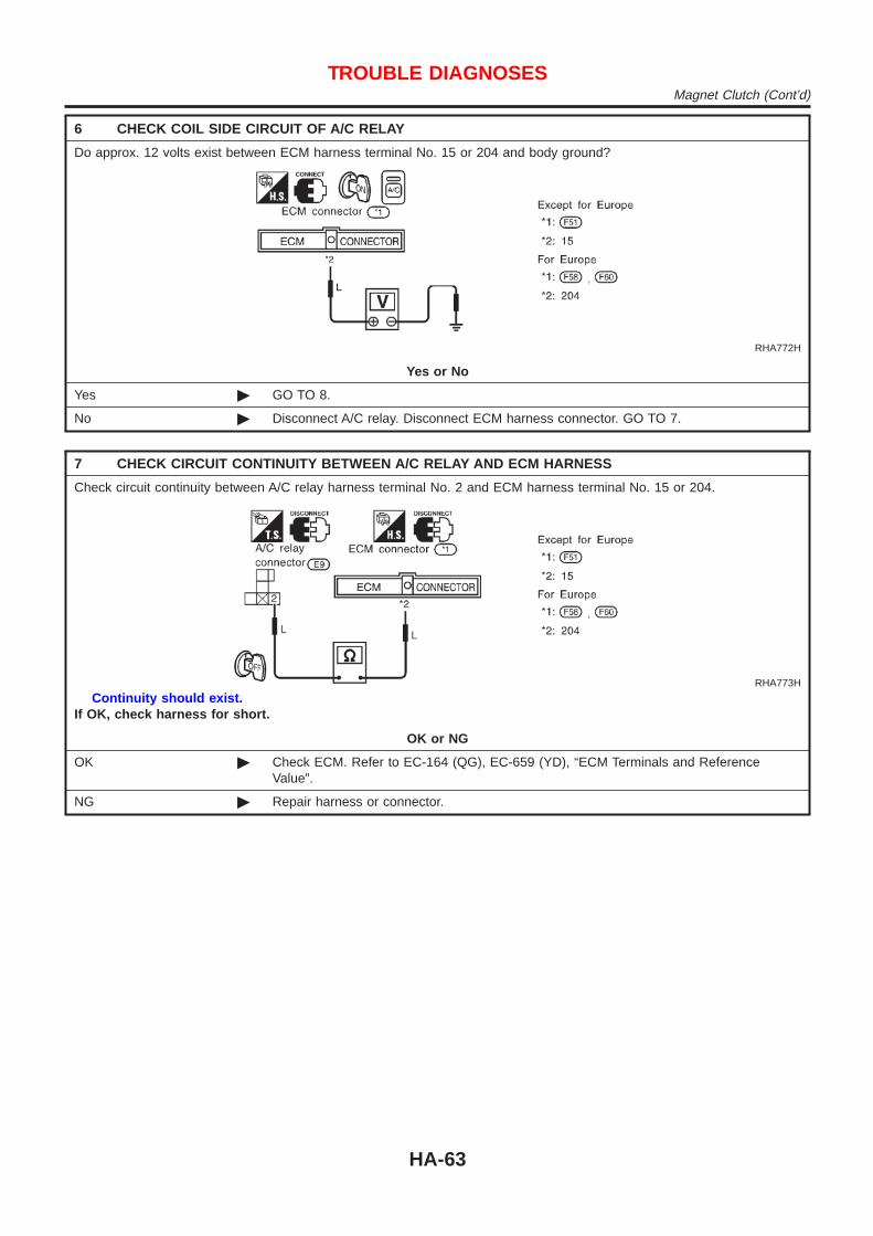
6 CHECK COIL SIDE CIRCUIT OF A/C RELAY
Do approx. 12 volts exist between ECM harness terminal No. 15 or 204 and body ground?
RHA772H
Yes or No
Yes © GO TO 8.
No © Disconnect A/C relay. Disconnect ECM harness connector. GO TO 7.
7 CHECK CIRCUIT CONTINUITY BETWEEN A/C RELAY AND ECM HARNESS
Check circuit continuity between A/C relay harness terminal No. 2 and ECM harness terminal No. 15 or 204.
RHA773H
Continuity should exist.If OK, check harness for short.
OK or NG
OK © Check ECM. Refer to EC-164 (QG), EC-659 (YD), “ECM Terminals and ReferenceValue”.
NG © Repair harness or connector.
TROUBLE DIAGNOSESMagnet Clutch (Cont’d)
HA-63

8 CHECK VOLTAGE FOR ECM
Do approx. 12 volts exist between ECM harness terminal No. 21 or 403 and body ground?
RHA774H
Yes or No
Yes © GO TO 9.
No © Check ECM. Refer to EC-164 (QG), EC-659 (YD), “ECM Terminals and ReferenceValue”.
9 CHECK POWER SUPPLY FOR DUAL-PRESSURE SWITCH
Do approx. 12 volts exist between dual-pressure switch harness terminal No. 2 and body ground?
RHA775H
Yes or No
Yes © GO TO 10.
No © Repair harness or connector.
10 CHECK DUAL-PRESSURE SWITCH
Refer to HA-67.
OK or NG
OK © GO TO 11.
No © Replace dual-pressure switch.
TROUBLE DIAGNOSESMagnet Clutch (Cont’d)
HA-64

11 CHECK CIRCUIT CONTINUITY BETWEEN DUAL-PRESSURE SWITCH AND HEATER CONTROL PANEL(A/C SWITCH)
Check circuit continuity between dual-pressure switch harness terminal No. 1 and heater control panel harness terminalNo. 7.
NHA490
Continuity should exist.If OK, check harness for short.
OK or NG
OK © GO TO 12.
NG © Repair harness or connector.
12 CHECK A/C SWITCH
Refer to HA-67.
OK or NG
OK © GO TO 13.
NG © Replace A/C switch.
13 CHECK HEATER CONTROL PANEL CIRCUIT
Check circuit continuity between heater control panel harness terminal No. 8 and No. 18.
NHA491
Continuity should exist.If OK, check harness for short.
OK or NG
OK © GO TO 14.
NG © Repair harness or connector.
TROUBLE DIAGNOSESMagnet Clutch (Cont’d)
HA-65
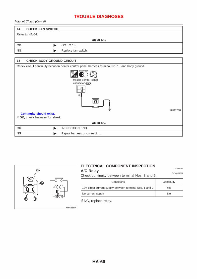
14 CHECK FAN SWITCH
Refer to HA-54.
OK or NG
OK © GO TO 15.
NG © Replace fan switch.
15 CHECK BODY GROUND CIRCUIT
Check circuit continuity between heater control panel harness terminal No. 13 and body ground.
RHA778H
Continuity should exist.If OK, check harness for short.
OK or NG
OK © INSPECTION END.
NG © Repair harness or connector.
RHA638H
ELECTRICAL COMPONENT INSPECTIONNJHA0192
A/C RelayNJHA0192S01
Check continuity between terminal Nos. 3 and 5.
Conditions Continuity
12V direct current supply between terminal Nos. 1 and 2 Yes
No current supply No
If NG, replace relay.
TROUBLE DIAGNOSESMagnet Clutch (Cont’d)
HA-66
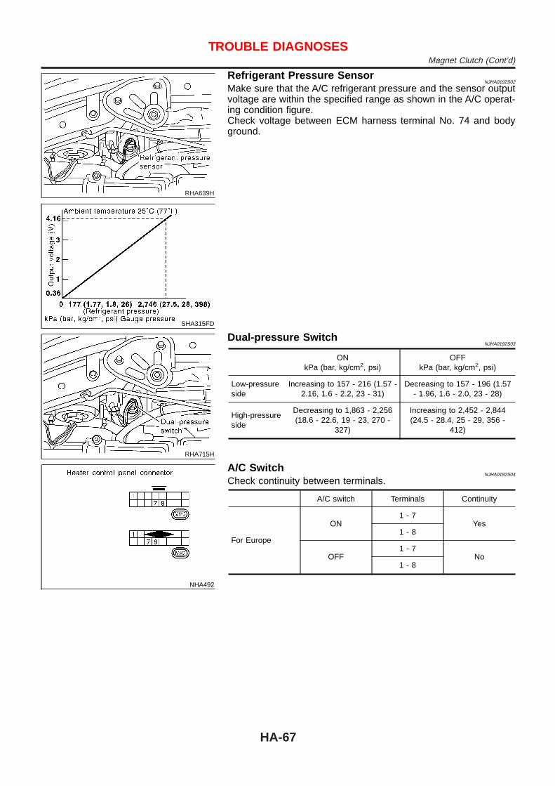
RHA639H
SHA315FD
Refrigerant Pressure SensorNJHA0192S02
Make sure that the A/C refrigerant pressure and the sensor outputvoltage are within the specified range as shown in the A/C operat-ing condition figure.Check voltage between ECM harness terminal No. 74 and bodyground.
RHA715H
Dual-pressure SwitchNJHA0192S03
ONkPa (bar, kg/cm2, psi)
OFFkPa (bar, kg/cm2, psi)
Low-pressureside
Increasing to 157 - 216 (1.57 -2.16, 1.6 - 2.2, 23 - 31)
Decreasing to 157 - 196 (1.57- 1.96, 1.6 - 2.0, 23 - 28)
High-pressureside
Decreasing to 1,863 - 2,256(18.6 - 22.6, 19 - 23, 270 -
327)
Increasing to 2,452 - 2,844(24.5 - 28.4, 25 - 29, 356 -
412)
NHA492
A/C SwitchNJHA0192S04
Check continuity between terminals.
A/C switch Terminals Continuity
For Europe
ON1 - 7
Yes1 - 8
OFF1 - 7
No1 - 8
TROUBLE DIAGNOSESMagnet Clutch (Cont’d)
HA-67

Insufficient CoolingTROUBLE DIAGNOSIS PROCEDURE FOR INSUFFICIENT COOLING
=NJHA0148
SYMPTOM:+ Insufficient Cooling.INSPECTION FLOW
NHA390
*1: HA-42*2: HA-72*3: HA-69
*4: HA-34*5: HA-33*6: HA-83
*7: EM-16 (QG),EM-85 (YD)
*8: EC-406 (QG) Europe,EC-730 (YD) Europe
TROUBLE DIAGNOSESInsufficient Cooling
HA-68

PERFORMANCE TEST DIAGNOSESNJHA0149
SHA419F
*1: HA-71*2: HA-71
*3: HA-72 *4: HA-43
TROUBLE DIAGNOSESInsufficient Cooling (Cont’d)
HA-69

SHA361FA
*1: HA-86 *2: HA-48 *3: EM-16 (QG),EM-85 (YD)
TROUBLE DIAGNOSESInsufficient Cooling (Cont’d)
HA-70

PERFORMANCE CHART=NJHA0150
Test ConditionNJHA0150S01
Testing must be performed as follows:Vehicle location: Indoors or in the shade (in a well-ventilated place)Doors: ClosedDoor window: OpenHood: OpenTEMP.: Max. COLDDischarge Air: Face VentREC switch: (Recirculation) setFAN speed: High speedEngine speed: Idle speedOperate the air conditioning system for 10 minutes before takingmeasurements.
Test ReadingNJHA0150S02
Recirculating-to-discharge Air Temperature TableNJHA0150S0201
Inside air (Recirculating air) at blower assembly inlet Discharge air temperature at center venti-lator
°C (°F)Relative humidity
%Air temperature
°C (°F)
50 - 60
20 (68) 6.0 - 8.8 (43 - 48)
25 (77) 9.5 - 12.8 (49 - 55)
30 (86) 14.1 - 17.7 (57 - 64)
60 - 70
20 (68) 8.8 - 11.6 (48 - 53)
25 (77) 12.8 - 16.2 (55 - 61)
30 (86) 17.7 - 21.1 (64 - 70)
TROUBLE DIAGNOSESInsufficient Cooling (Cont’d)
HA-71

Ambient Air Temperature-to-operating Pressure Table=NJHA0150S0202
Ambient airHigh-pressure (Discharge side)
kPa (bar, kg/cm2, psi)Low-pressure (Suction side)
kPa (bar, kg/cm2, psi)Relative humidity%
Air temperature°C (°F)
50 - 70
20 (68)659 - 805
(6.590 - 8.052, 6.72 - 8.21,95.6 - 116.7)
171 - 214(1.706 - 213.8, 1.74 - 2.18,
24.7 - 31.0)
25 (77)799 - 980
(7.993 - 9.797, 8.15 - 9.99,115.9 - 142.1)
185 - 220(1.854 - 2.197, 1.89 - 2.24,
26.9 - 31.9)
30 (86)953 - 1,170
(9.532 - 11.700, 9.72 - 11.93,138.2 - 169.6)
199 - 240(1.991 - 2.403, 2.03 - 2.45,
28.9 - 34.8)
35 (95)1,121 - 1,363
(11.209 - 13.632, 11.43 -13.90, 162.5 - 197.7)
228 - 282(2.275 - 2.824, 2.32 - 2.88,
33.0 - 41.0)
40 (104)1,298 - 1,584
(12.984 - 15.838, 13.24 -16.15, 188.3 - 229.7)
273 - 333(2.726 - 3.334, 2.78 - 3.40,
39.5 - 48.3)
TROUBLE DIAGNOSES FOR ABNORMAL PRESSURENJHA0151
Whenever system’s high and/or low side pressure is abnormal, diagnose using a manifold gauge. The markerabove the gauge scale in the following tables indicates the standard (normal) pressure range. Since the stan-dard (normal) pressure, however, differs from vehicle to vehicle, refer to HA-72 (“Ambient air temperature-to-operating pressure table”).
TROUBLE DIAGNOSESInsufficient Cooling (Cont’d)
HA-72
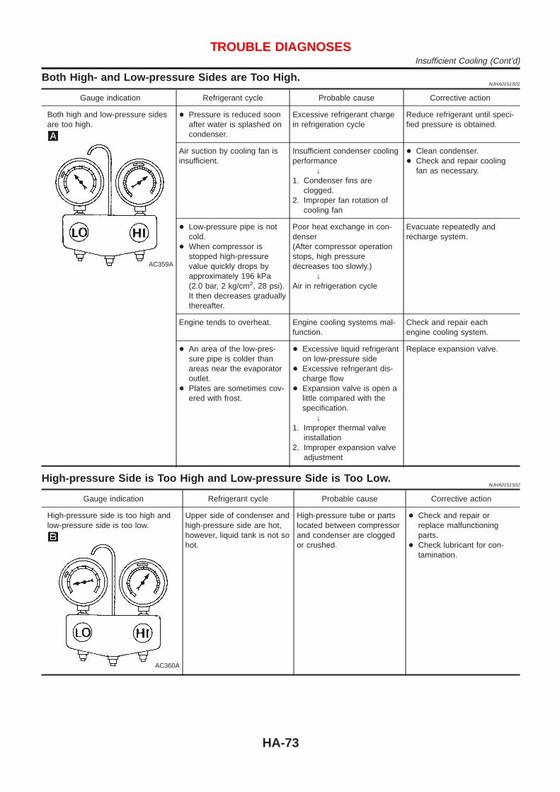
Both High- and Low-pressure Sides are Too High.NJHA0151S01
Gauge indication Refrigerant cycle Probable cause Corrective action
Both high and low-pressure sidesare too high.
AC359A
+ Pressure is reduced soonafter water is splashed oncondenser.
Excessive refrigerant chargein refrigeration cycle
Reduce refrigerant until speci-fied pressure is obtained.
Air suction by cooling fan isinsufficient.
Insufficient condenser coolingperformance
↓1. Condenser fins are
clogged.2. Improper fan rotation of
cooling fan
+ Clean condenser.+ Check and repair cooling
fan as necessary.
+ Low-pressure pipe is notcold.
+ When compressor isstopped high-pressurevalue quickly drops byapproximately 196 kPa(2.0 bar, 2 kg/cm2, 28 psi).It then decreases graduallythereafter.
Poor heat exchange in con-denser(After compressor operationstops, high pressuredecreases too slowly.)
↓Air in refrigeration cycle
Evacuate repeatedly andrecharge system.
Engine tends to overheat. Engine cooling systems mal-function.
Check and repair eachengine cooling system.
+ An area of the low-pres-sure pipe is colder thanareas near the evaporatoroutlet.
+ Plates are sometimes cov-ered with frost.
+ Excessive liquid refrigeranton low-pressure side
+ Excessive refrigerant dis-charge flow
+ Expansion valve is open alittle compared with thespecification.
↓1. Improper thermal valve
installation2. Improper expansion valve
adjustment
Replace expansion valve.
High-pressure Side is Too High and Low-pressure Side is Too Low.NJHA0151S02
Gauge indication Refrigerant cycle Probable cause Corrective action
High-pressure side is too high andlow-pressure side is too low.
AC360A
Upper side of condenser andhigh-pressure side are hot,however, liquid tank is not sohot.
High-pressure tube or partslocated between compressorand condenser are cloggedor crushed.
+ Check and repair orreplace malfunctioningparts.
+ Check lubricant for con-tamination.
TROUBLE DIAGNOSESInsufficient Cooling (Cont’d)
HA-73

High-pressure Side is Too Low and Low-pressure Side is Too High.NJHA0151S03
Gauge indication Refrigerant cycle Probable cause Corrective action
High-pressure side is too low andlow-pressure side is too high.
AC356A
High and low-pressure sidesbecome equal soon aftercompressor operation stops.
Compressor pressure opera-tion is improper.
↓Damaged inside compressorpackings
Replace compressor.
No temperature differencebetween high and low-pres-sure sides
Compressor pressure opera-tion is improper.
↓Damaged inside compressorpackings.
Replace compressor.
Both High- and Low-pressure Sides are Too Low.NJHA0151S04
Gauge indication Refrigerant cycle Probable cause Corrective action
Both high- and low-pressure sidesare too low.
AC353A
+ There is a big temperaturedifference betweenreceiver drier outlet andinlet. Outlet temperature isextremely low.
+ Liquid tank inlet andexpansion valve arefrosted.
Liquid tank inside is slightlyclogged.
+ Replace liquid tank.+ Check lubricant for con-
tamination.
+ Temperature of expansionvalve inlet is extremelylow as compared withareas near liquid tank.
+ Expansion valve inlet maybe frosted.
+ Temperature differenceoccurs somewhere inhigh- pressure side
High-pressure pipe locatedbetween receiver drier andexpansion valve is clogged.
+ Check and repair malfunc-tioning parts.
+ Check lubricant for con-tamination.
+ Expansion valve and liquidtank are warm or only coolwhen touched.
Low refrigerant charge↓
Leaking fittings or compo-nents
Check refrigerant for leaks.Refer to “Checking Refriger-ant Leaks”, HA-93.
There is a big temperaturedifference between expan-sion valve inlet and outletwhile the valve itself isfrosted.
Expansion valve closes alittle compared with thespecification.
↓1. Improper expansion valve
adjustment2. Malfunctioning thermal
valve3. Outlet and inlet may be
clogged.
+ Remove foreign particlesby using compressed air.
+ Check lubricant for con-tamination.
An area of the low-pressurepipe is colder than areasnear the evaporator outlet.
Low-pressure pipe is cloggedor crushed.
+ Check and repair malfunc-tioning parts.
+ Check lubricant for con-tamination.
Air flow volume is notenough or is too low.
Evaporator is frozen. + Check thermo controlamp. operation.
+ Replace compressor.
TROUBLE DIAGNOSESInsufficient Cooling (Cont’d)
HA-74

Low-pressure Side Sometimes Becomes Negative.NJHA0151S05
Gauge indication Refrigerant cycle Probable cause Corrective action
Low-pressure side sometimesbecomes negative.
AC354A
+ Air conditioning systemdoes not function anddoes not cyclically coolthe compartment air.
+ The system constantlyfunctions for a certainperiod of time after com-pressor is stopped andrestarted.
Refrigerant does not dis-charge cyclically.
↓Moisture is frozen at expan-sion valve outlet and inlet.
↓Water is mixed with refriger-ant.
+ Drain water from refriger-ant or replace refrigerant.
+ Replace liquid tank.
Low-pressure Side Becomes Negative.NJHA0151S06
Gauge indication Refrigerant cycle Probable cause Corrective action
Low-pressure side becomes nega-tive.
AC362A
Liquid tank or front/rear sideof expansion valve’s pipe isfrosted or dewed.
High-pressure side is closedand refrigerant does not flow.
↓Expansion valve or liquidtank is frosted.
Leave the system at restuntil no frost is present. Startit again to check whether ornot the problem is caused bywater or foreign particles.+ If water is the cause, ini-
tially cooling is okay. Thenthe water freezes causinga blockage. Drain waterfrom refrigerant or replacerefrigerant.
+ If due to foreign particles,remove expansion valveand remove particles withdry and compressed air(not shop air).
+ If either of the abovemethods cannot correctthe problem, replaceexpansion valve.
+ Replace liquid tank.+ Check lubricant for con-
tamination.
TROUBLE DIAGNOSESInsufficient Cooling (Cont’d)
HA-75

Insufficient HeatingTROUBLE DIAGNOSIS PROCEDURE FOR INSUFFICIENT HEATING
=NJHA0152
SYMPTOM: Insufficient heating.INSPECTION FLOW
NHA391
*1: LC-18 (QG),LC-44 (YD)
*2: LC-12 (QG),LC-38 (YD)
*3: LC-15 (QG),LC-41 (YD)
*4: LC-20 (QG),LC-45 (YD)
*5: HA-34*6: HA-33
TROUBLE DIAGNOSESInsufficient Heating
HA-76
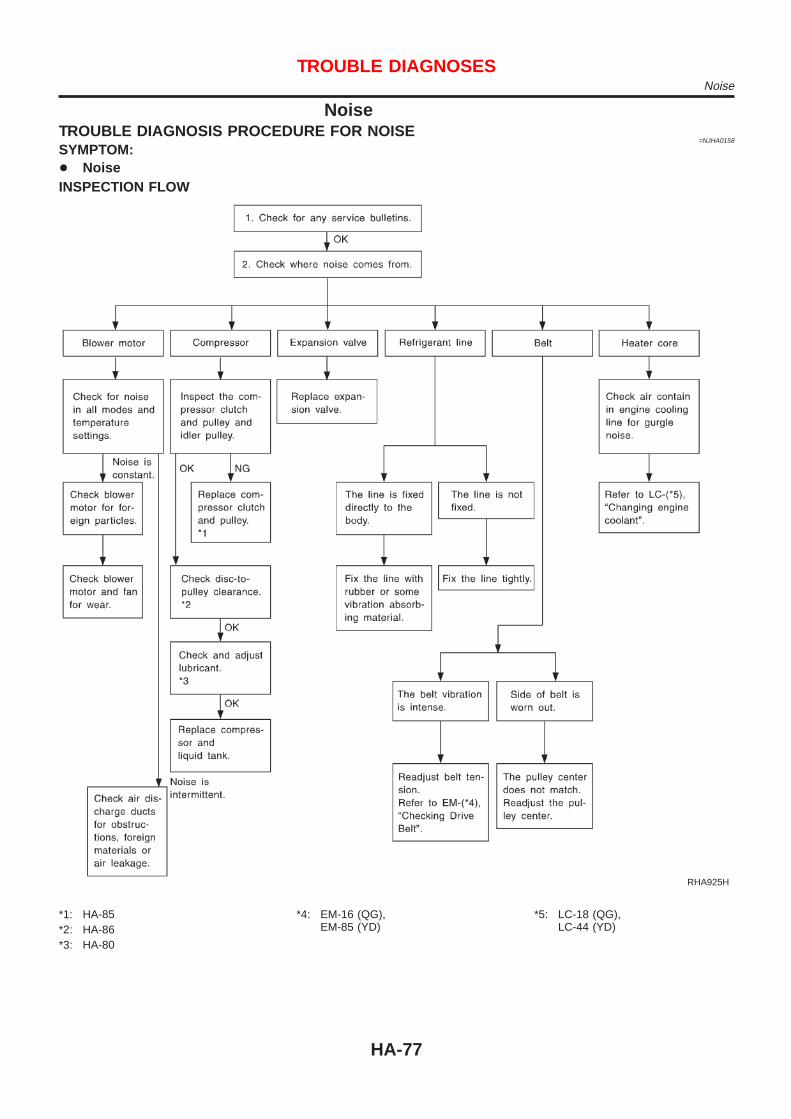
NoiseTROUBLE DIAGNOSIS PROCEDURE FOR NOISE
=NJHA0158
SYMPTOM:+ NoiseINSPECTION FLOW
RHA925H
*1: HA-85*2: HA-86*3: HA-80
*4: EM-16 (QG),EM-85 (YD)
*5: LC-18 (QG),LC-44 (YD)
TROUBLE DIAGNOSESNoise
HA-77

HFC-134a (R-134a) Service ProcedureNJHA0159
SETTING OF SERVICE TOOLS AND EQUIPMENTNJHA0159S01
Discharging RefrigerantNJHA0159S0101
WARNING:Avoid breathing A/C refrigerant and lubricant vapor or mist. Exposure may irritate eyes, nose andthroat. Remove HFC-134a (R-134a) from A/C system using certified service equipment meeting require-ments of HFC-134a (R-134a) recycling equipment or HFC-134a (R-134a) recovery equipment. If acci-dental system discharge occurs, ventilate work area before resuming service. Additional health andsafety information may be obtained from refrigerant and lubricant manufacturers.
SHA539DE
Evacuating System and Charging RefrigerantNJHA0159S0102
SHA540DC
SERVICE PROCEDUREHFC-134a (R-134a) Service Procedure
HA-78

SHA383F
*1: HA-80*2: HA-93
*3: HA-94 *4: HA-69
SERVICE PROCEDUREHFC-134a (R-134a) Service Procedure (Cont’d)
HA-79

Maintenance of Lubricant Quantity inCompressor
NJHA0160
The lubricant in the compressor circulates through the system withthe refrigerant. Add lubricant to compressor when replacing anycomponent or after a large gas leakage occurred. It is important tomaintain the specified amount.If lubricant quantity is not maintained properly, the following mal-functions may result:+ Lack of lubricant: May lead to a seized compressor+ Excessive lubricant: Inadequate cooling (thermal exchange
interference)
LUBRICANTNJHA0160S01
Name: Nissan A/C System Oil Type R for DKV-11G compres-sorPart number: KLH00-PAGR0
Name: Nissan A/C System Oil Type S for CSV613 compressorPart number: KLH00-PAGS0
CHECKING AND ADJUSTINGNJHA0160S02
Adjust the lubricant quantity according to the test group shownbelow.
1 LUBRICANT RETURN OPERATION
Can lubricant return operation be performed?+ A/C system works properly.+ There is no evidence of a large amount of lubricant leakage.
Yes or No
Yes © GO TO 2.
No © GO TO 3.
2 PERFORM LUBRICANT RETURN OPERATION, PROCEEDING AS FOLLOWS
1. Start engine, and set the following conditions:+ Test condition
Engine speed: Idling to 1,200 rpmA/C or AUTO switch: ONBlower speed: Max. positionTemp. control: Optional [Set so that intake air temperature is 25 to 30°C (77 to 86°F).]
2. Perform lubricant return operation for about 10 minutes.3. Stop engine.CAUTION:If excessive lubricant leakage is noted, do not perform the lubricant return operation.
© GO TO 3.
3 CHECK COMPRESSOR
Should the compressor be replaced?
Yes or No
Yes © GO TO HA-82.
No © GO TO 4.
SERVICE PROCEDUREMaintenance of Lubricant Quantity in Compressor
HA-80

4 CHECK ANY PART
Is there any part to be replaced? (Evaporator, condenser, liquid tank or in case there is evidence of a large amount oflubricant leakage.)
Yes or No
Yes © GO TO HA-82.
No © Carry out the A/C performance test.
SERVICE PROCEDUREMaintenance of Lubricant Quantity in Compressor (Cont’d)
HA-81

Lubricant Adjusting Procedure for ComponentsReplacement Except Compressor
=NJHA0160S0201
After replacing any of the following major components, add thecorrect amount of lubricant to the system.Amount of lubricant to be added
Part replaced
Lubricant to be added tosystem
RemarksAmount of lubricant
m! (Imp fl oz)
Evaporator 75 (2.6) —
Condenser 75 (2.6) —
Liquid tank 5 (0.2)Add if compressor is not
replaced. *1
In case of refrigerantleak
30 (1.1) Large leak
— Small leak *2
*1: If compressor is replaced, addition of lubricant is included in the table.*2: If refrigerant leak is small, no addition of lubricant is needed.
Lubricant Adjustment Procedure for CompressorReplacement
NJHA0160S0202
1. Discharge refrigerant into the refrigerant recovery/recyclingequipment. Measure lubricant discharged into the recovery/recycling equipment.
2. Drain the lubricant from the “old” (removed) compressor into agraduated container and recover the amount of lubricantdrained.
3. Drain the lubricant from the “new” compressor into a separate,clean container.
4. Measure an amount of new lubricant installed equal to amountdrained from “old” compressor. Add this lubricant to “new” com-pressor through the suction port opening.
5. Measure an amount of new lubricant equal to the amountrecovered during discharging. Add this lubricant to “new” com-pressor through the suction port opening.
6. If the liquid tank also needs to be replaced, add an additional5 m! (0.2 Imp fl oz) of lubricant at this time.Do not add this 5 m ! (0.2 Imp fl oz) of lubricant if onlyreplacing the compressor.
SERVICE PROCEDUREMaintenance of Lubricant Quantity in Compressor (Cont’d)
HA-82

RHA065DH
CompressorREMOVAL AND INSTALLATION
NJHA0161
RHA803H
SERVICE PROCEDUREMaintenance of Lubricant Quantity in Compressor (Cont’d)
HA-83

RHA804H
Compressor Clutch — CSV613 (CALSONICmake)OVERHAUL
NJHA0211
RHA805H
SERVICE PROCEDURECompressor (Cont’d)
HA-84

RHA136E
REMOVALNJHA0212
+ When removing center bolt, hold clutch disc with clutch discwrench.
RHA399FA
RHA124FA
+ Remove the clutch disc using the clutch disc puller.Insert the holder’s three pins into the holes in the clutch disc.Rotate the holder clockwise to hook it onto the plate. Then,tighten the center bolt to remove the clutch disc.After removing the clutch disc, remove the shims from eitherthe drive shaft or the clutch disc.
RHA138E
+ Remove the snap ring using external snap ring pliers.
RHA139E
+ Pulley removalPosition the center pulley puller on the end of the drive shaft,and remove the pulley assembly using any commercially avail-able pulley puller.To prevent the pulley groove from being deformed, thepuller claws should be positioned onto the edge of thepulley assembly.
SERVICE PROCEDURECompressor Clutch — CSV613 (CALSONIC make) (Cont’d)
HA-85

RHA806H
+ Remove the connector from the connector bracket.
RHA145E
+ Remove the snap ring using external snap ring pliers.
RHA126F
INSPECTIONNJHA0213
Clutch DiscNJHA0213S01
If the contact surface shows signs of damage due to excessiveheat, replace clutch disc and pulley.
PulleyNJHA0213S02
Check the appearance of the pulley assembly. If the contact sur-face of pulley shows signs of excessive grooving, replace clutchdisc and pulley. The contact surfaces of the pulley assembly shouldbe cleaned with a suitable solvent before reinstallation.
CoilNJHA0213S03
Check coil for loose connection or cracked insulation.
RHA142E
INSTALLATIONNJHA0214
+ Install the field coil.Be sure to align the coil’s pin with the hole in the com-pressor’s front head.
+ Install the field coil harness clip using a screwdriver.
SERVICE PROCEDURECompressor Clutch — CSV613 (CALSONIC make) (Cont’d)
HA-86

RHA143E
+ Install the pulley assembly using the installer and a handpress, and then install the snap ring using snap ring pliers.
RHA127F
+ Install the clutch disc on the drive shaft, together with theoriginal shim(s). Press the clutch disc down by hand.
RHA086E
+ Using the holder to prevent clutch disc rotation, tighten the boltto 14 N·m (1.4 kg-m, 10 ft-lb) torque.After tightening the bolt, check that the pulley rotatessmoothly.
RHA087E
+ Check clearance around the entire periphery of clutch disc.Disc-to-pulley clearance:
0.3 - 0.6 mm (0.012 - 0.024 in)If the specified clearance is not obtained, replace adjustingspacer and readjust.
Break-in OperationNJHA0214S01
When replacing compressor clutch assembly, always carry out thebreak-in operation. This is done by engaging and disengaging theclutch about thirty times. Break-in operation raises the level oftransmitted torque.
SERVICE PROCEDURECompressor Clutch — CSV613 (CALSONIC make) (Cont’d)
HA-87

Heater & Cooling Unit (Heater Core)REMOVAL
NJHA0193
RHA807H
1. Drain the cooling system. Refer to LC-18 (QG), LC-44 (YD),“Changing Engine Coolant”.
2. Discharge the A/C system. Refer to HA-78.3. Disconnect the two heater hoses from inside the engine com-
partment.4. Remove the blower unit. Refer to HA-89.5. Remove the steering member assembly. Refer to BT-25,
“Instrument Panel Assembly”.6. Remove the heater unit.7. Separate the heater & cooling unit case, and remove the
heater core.
INSTALLATIONNJHA0194
Install in the reverse order of removal.When filling radiator with coolant, refer to LC-19 (QG), LC-45(YD), “Refilling Engine Coolant”.Recharge the A/C system. Refer to HA-78.
RHA673H
A/C EvaporatorREMOVAL
NJHA0204
1. Discharge the A/C system. Refer to HA-78.2. Disconnect the two refrigerant lines from the engine compart-
ment.Cap the A/C lines to prevent moisture from entering the sys-tem.
3. Remove the grommet cover, grommet and expansion valvecover from the engine compartment.
4. Remove the glove box, instrument lower assist panel, instru-ment lower cover and drink holder. Refer to BT-25.
SERVICE PROCEDUREHeater & Cooling Unit (Heater Core)
HA-88

RHA674H
5. Remove the five screws fixed heater & cooling unit lowercover.
6. Slide the A/C evaporator to rear side.7. Slide the heater & cooling unit lower cover to rear side and
then remove it.8. Slide the A/C evaporator to the front side and then remove the
A/C evaporator.
INSTALLATIONNJHA0205
Install in the reverse order of removal.Recharge the A/C system. Refer to HA-78.
Blower UnitREMOVAL
NJHA0195
RHA676HA
SERVICE PROCEDUREA/C Evaporator (Cont’d)
HA-89

1. Remove the instrument panel assembly. Refer to BT-25,“Instrument Panel Assembly”.
2. Disconnect the blower motor and resistor connector.3. Remove blower unit.
INSTALLATIONNJHA0196
Install in the reverse order of removal.
SERVICE PROCEDUREBlower Unit (Cont’d)
HA-90

Refrigerant LinesREMOVAL AND INSTALLATION
=NJHA0167
+ Refer to page HA-3 reading “Precautions for Refrigerant Connection”.
RHA808HA
SERVICE PROCEDURERefrigerant Lines
HA-91
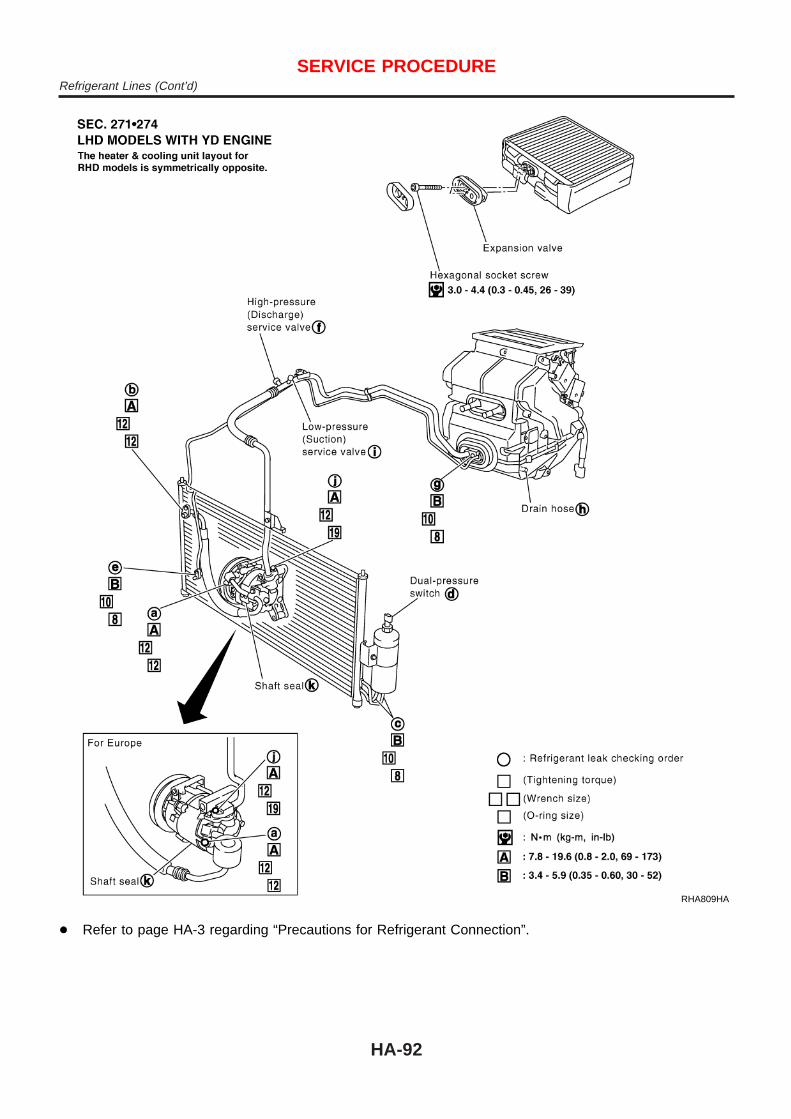
RHA809HA
+ Refer to page HA-3 regarding “Precautions for Refrigerant Connection”.
SERVICE PROCEDURERefrigerant Lines (Cont’d)
HA-92

CHECKING REFRIGERANT LEAKS=NJHA0168
Preliminary CheckNJHA0168S01
Perform a visual inspection of all refrigeration parts, fittings, hoses,and components for signs of A/C lubricant leakage, damage andcorrosion. Take note of the areas with A/C lubricant leakage toallow extra time in these areas with electronic leak detector.
SHA705EB
Precautions for Handling Leak DetectorNJHA0168S02
When performing a refrigerant leak check, use an A/C leak detec-tor or equivalent. Ensure that the instrument is calibrated and setproperly per the operating instructions.The leak detector is a delicate device. In order to use the leakdetector properly, read the operating instructions and perform anyspecified maintenance.Other gases in the work area or substances on the A/Ccomponents, for example, anti-freeze, windshield washerfluid, solvents and lubricants, may falsely trigger the leakdetector. Make sure the surfaces to be checked are clean.Clean with a dry cloth or blow off with shop air. Do not allowthe sensor tip of the detector to contact with any substance.This can also cause false readings and may damage the detec-tor.
SHA707EA
1. Position probe approximately 5 mm (3/16 in) away from pointto be checked.
SHA706E
2. When testing, circle each fitting completely with probe.
SERVICE PROCEDURERefrigerant Lines (Cont’d)
HA-93

SHA708EA
3. Move probe along component approximately 25 to 50 mm (1to 2 in)/sec.
Checking ProcedureNJHA0168S03
To prevent inaccurate or false readings, make sure there is norefrigerant vapor, shop chemicals, or cigarette smoke in thevicinity of the vehicle. Perform the leak test in calm area (lowair/wind movement) so that the leaking refrigerant is not dis-persed.1. Turn engine off.2. Connect a suitable A/C manifold gauge set to the A/C service
ports.3. Check if the A/C refrigerant pressure is at least 345.2 kPa (3.45
bar, 3.52 kg/cm2, 50.1 psi) above 16°C (61°F). If less thanspecification, recover/evacuate and recharge the system withthe specified amount of refrigerant.
NOTE:At temperatures below 16°C (61°F), leaks may not be detectedsince the system may not reach 345.2 kPa (3.45 bar, 3.52 kg/cm2,50.1 psi).4. Conduct the leak test from the high side (compressor dis-
charge a to evaporator inlet g) to the low side (evaporator drainhose h to shaft seal k). Refer to HA-91. Perform a leak checkfor the following areas carefully. Clean the component to bechecked and move the leak detector probe completely aroundthe connection/component.
+ CompressorCheck the fitting of high and low pressure hoses, relief valveand shaft seal.
+ Liquid tankCheck the pressure switch, refrigerant pressure sensor, tubefitting, weld seams and the fusible plug mount.
+ Service valvesCheck all around the service valves. Ensure service valve capsare secured on the service valves (to prevent leaks).
NOTE:After removing A/C manifold gauge set from service valves, wipeany residue from valves to prevent any false readings by leakdetector.+ Cooling unit (Evaporator)
With engine OFF, turn blower fan on “High” for at least 15seconds to dissipate any refrigerant trace in the cooling unit.Wait a minimum of 10 minutes accumulation time (refer to themanufacturer’s recommended procedure for actual wait time)before inserting the leak detector probe into the drain hose.Keep the probe inserted for at least ten seconds. Use cautionnot to contaminate the ptobe tip with water or dirt that may bein the drain hose.
SERVICE PROCEDURERefrigerant Lines (Cont’d)
HA-94

5. If a leak detector detects a leak, verify at least once by blow-ing compressed air into area of suspected leak, then repeatcheck as outlined above.
6. Do not stop when one leak is found. Continue to check foradditional leaks at all system components.If no leaks are found, perform steps 7 - 10.
7. Start engine.8. Set the heater A/C control as follows:1) A/C switch ON.2) Face mode3) Recirculation position4) Max cold temperature5) Fan speed high9. Run engine at 1,500 rpm for at least 2 minutes.10. Turn engine off and perform leak check again following steps
4 through 6 above.
SHA839E
Refrigerant leaks should be checked immediately afterstopping the engine. Begin with the leak detector at thecompressor. The pressure on the high pressure side willgradually drop after refrigerant circulation stops and pres-sure on the low pressure side will gradually rise, as shownin the graph. Some leaks are more easily detected whenpressure is high.
11. Discharge A/C system using approved refrigerant recoveryequipment. Repair the leaking fitting or component as neces-sary.
12. Evacuate and recharge A/C system and perform the leak testto confirm no refrigerant leaks.
13. Conduct A/C performance test to ensure system worksproperly.
BeltTENSION ADJUSTMENT
NJHA0169
+ Refer to EM-16 (QG), EM-85 (YD), “Checking Drive Belt”.
SERVICE PROCEDURERefrigerant Lines (Cont’d)
HA-95

Idle Air Control Valve (IACV) — Auxiliary AirControl (AAC) ValveINSPECTION
NJHA0199
+ Refer to EC-376 (QG), “System Description”.
RHA680H
Ventilation Air FilterFUNCTION
NJHA0171
Air inside passenger compartment is kept clean at either recircula-tion or fresh mode by installing ventilation air filter into cooling unit.
SHA868E
REPLACEMENT TIMINGNJHA0172
Replace ventilation air filter.Refer to MA-4, “PERIODIC MAINTENANCE”.Caution label is fixed inside the glove box.
RHA681H
REPLACEMENT PROCEDURENJHA0173
+ Remove glove box.+ Remove filter cover.+ Take out the ventilation air filter from blower unit.+ Replace with new one and reinstall on blower unit.+ Reinstall glove box.
SERVICE PROCEDUREIdle Air Control Valve (IACV) — Auxiliary Air Control (AAC) Valve
HA-96

CompressorNJHA0174
Model CALSONIC make CSV613
Type Swash plate (Variable displacement)
Displacement cm3 (cu in)/rev. 6.0 - 125 (0.37 - 7.63)
Direction of rotation Clockwise (viewed from drive end)
Drive beltQG engine model: Poly VYD engine model: Type A
LubricantNJHA0175
Model CALSONIC make CSV613
Name Nissan A/C System Oil Type S
Part number KLH00-PAGS0
Capacitym! (Imp fl oz)
Total in system 180 - 200 (6.3 - 7.0)
Compressor (Service part) charging amount 180 - 200 (6.3 - 7.0)
RefrigerantNJHA0176
Type HFC-134a (R-134a)
Capacity kg (lb) 0.45 - 0.55 (0.99 - 1.21)
Engine Idling Speed (When A/C is On)NJHA0177
+ Refer to EC-593 (QG), EC-834 (YD), “Idle Speed and Ignition Timing”.
Belt TensionNJHA0178
+ Refer to EM-16 (QG), EM-85 (YD), “Checking Drive Belts”.
SERVICE DATA AND SPECIFICATIONS (SDS)Compressor
HA-97

SERVICE DATA AND SPECIFICATIONS (SDS)Belt Tension (Cont’d)
HA-98