AIR COMPRESSOR PDS400S-6B1 · INSTRUCTIONAL MANUAL AIR COMPRESSOR PDS400S-6B1 MMD Equipment Inc....
52
INSTRUCTIONAL MANUAL AIR COMPRESSOR PDS400S-6B1 MMD Equipment Inc. 121 High Hill Road Swedesboro, NJ 08085 Tel: (800) 433-1382 Fax: (856) 467-5235 www.mmdequipment.com
Transcript of AIR COMPRESSOR PDS400S-6B1 · INSTRUCTIONAL MANUAL AIR COMPRESSOR PDS400S-6B1 MMD Equipment Inc....

INSTRUCTIONAL MANUAL
AIR COMPRESSOR
PDS400S-6B1
MMD Equipment Inc. 121 High Hill Road
Swedesboro, NJ 08085 Tel: (800) 433-1382 Fax: (856) 467-5235
www.mmdequipment.com

Preface
◆ This manual explains and illustrates proper handling of the unit, method of daily inspection and
maintenance to enhance the performance of AIRMAN’s compressors.
◆ In order to use a machine safely, people with sufficient knowledge and sufficient technology need to deal
with it. ◆ Before operating the unit, read the manual carefully, fully understand its operation and maintenance
requirement. Maintain “SAFETY OPERATION AND PROPER MAINTENANCE OF THE UNIT”.
Be sure to follow safety warnings and cautions given in the manual. Unsafe operation could cause serious injury or death.
◆ For details of handling, maintenance and safety of the engine, see the Engine Operation Manual. ◆ Keep the manual available at all times for the operator or safety supervisor. ◆ If the manual is lost or damaged, place an order with your dealer for another copy. ◆ Be sure that the manual is included with the unit when it is handed over to another user. ◆ There may be some inconsistency in detail between the manual and the actual machine due to
improvements of the machine. Ask your dealer if you have any questions or problems. ◆ If you have any questions about the unit, please inform us the model and serial number. A plate
stamped with the model and serial number is attached to side of the unit.
A990054

Table of Contents
1. Safety ....................................................................................................................................................... 1-1 1.1 Caution before Operation ................................................................................................................ 1-2 1.2 Caution during Operation ................................................................................................................ 1-5 1.3 Caution during Inspection and Maintenance ................................................................................... 1-7 1.4 Safety Warning Labels .................................................................................................................... 1-10
2. Part Names .............................................................................................................................................. 2-1
2.1 Unit Appearance and Part Names ................................................................................................... 2-1 2.2 Internal Components and Part Names ............................................................................................ 2-2
3. Installation ............................................................................................................................................... 3-1
3.1 Transportation .............................................................................................................................. 3-1 3.2 Towing the Unit .............................................................................................................................. 3-2 3.3 Location and Installation ................................................................................................................... 3-3
4. Operation ................................................................................................................................................. 4-1
4.1 Instrument panel ............................................................................................................................ 4-1 4.2 Door ................................................................................................................................................. 4-2 4.3 Check before Starting the Unit .................................................................................................... 4-2 4.4 Unit Operation ................................................................................................................................ 4-7 4.5 Stopping Procedures..................................................................................................................... 4-11
5. Periodic Inspection/Maintenance .......................................................................................................... 5-1
5.1 Important items as Periodic and Maintenance or after Maintenance .............................................. 5-1 5.2 Daily Inspection and keeping Operation Log ................................................................................... 5-2 5.3 Inspection on Separator Receiver Tank............................................................................................ 5-2 5.4 Periodic Inspection List ................................................................................................................... 5-3 5.5 Periodic Replacement of Parts ......................................................................................................... 5-4 5.6 Maintenance ..................................................................................................................................... 5-5
6. Maintenance/Adjustment ....................................................................................................................... 6-1
6.1 Maintenance of Battery ..................................................................................................................... 6-1 6.2 Troubleshooting ................................................................................................................................ 6-3
7. Storage of the Unit ................................................................................................................................. 7-1
7.1 Preparation for Long-term Storage ................................................................................................. 7-1 8. Specifications ......................................................................................................................................... 8-1
8.1 Specifications.................................................................................................................................... 8-1 8.2 Outline drawing .............................................................................................................................. 8-1
9. Wiring Diagram ....................................................................................................................................... 1 9-1
10. Piping Diagram ....................................................................................................................................... 10-1

1.Safety
1-1
This manual explains and illustrates general requirements for safety. Read all safety requirements carefully and fully understand the contents before starting the machine. For your better recognition, according to the degree of potential danger, safety messages are classified into three hierarchical categories, namely, , , and with a caution symbol -attached to each message. When one of these messages is , please take preventive measures and carry out “SAFETY OPERATION AND PROPER MAINTENANCE OF THE UNIT”.
DANGER indicates an imminently hazardous situation which, if not avoided, will result in death or serious injury. This signal word is to be limited to the most extreme situations.
WARNING indicates a potentially hazardous situation which, if not avoided, could result in death or serious injury. CAUTION indicates a potentially hazardous situation which, if not avoided, may result in minor or moderate injury. It may also be used to alert against unsafe practices. IMPORTANT indicates important caution messages for the performance or durability of the unit.
Follow warnings mentioned in this manual. This manual does not describe all safety items. We, therefore, advise you to pay special attention to all items (even though they may not be described in the manual) for your safety.

1.Safety
1-2
1.1 Caution before Operation
Follow the safety instructions Read each instruction plate which is displayed in the manual or on the unit carefully, understand its content and follow the indications thereof. Keep the Safety Warning labels clean. When they are damaged or missing, apply new ones. Do not modify the machine without prior approval. The safety may be compromised, functions may be deteriorated, or machine life may be shortened. Never use the unit for the purpose of compression of gases other than air, or as a vacuum pump. Otherwise, serious accidents may occur.
TR0086
Ventilation Exhaust gas from the engine is poisonous, and could cause death when inhaled. Avoid using the machine in an insufficiently ventilated building or tunnel.
PC002
Air pressurized construction method prohibited Never use the unit directly or indirectly for the following purposes: Never use the unit for respirator equipment by which
compressed air is supplied for human consumption. The compressed air contains carbon monoxide and other contaminants, and such air may cause serious injury or even death if used by a person for respiration. This compressor is not designed for air pressurized
construction method and underwater diving jobs. Never use compressed air for human consumption such as pressurizing diving air tanks. Consumption of compressed air can cause death while diving.
TR0201

1.Safety
1-3
Piping or the hose from this machine service valve should use what can be borne enough for the discharge pressure of this machine. Please connect piping or a hose to this machine service valve firmly before operation and during operation. If the connection part is loosening, there is a possibility of piping or a hose separating and getting
seriously injured. Please remove after closing a service valve and extracting pressure remained, in case piping or a hose is removed. If pressure remained should remain, a near thing blows away or there is a possibility of a hose whipping, causing a phenomenon and getting seriously injured. In order to use it safely, please read the handling of the work tools often used.
Safety outfit
When handling machine, do not wear; loose clothes clothes with unbuttoned sleeves hanging tie or scarf accessories such as dangling jewelry Such outfit could be caught in the machine or dragged in the rotating portion of the machine, and this could cause a serious injury.
Handling battery
Keep flames away from battery. Battery may generate hydrogen gas and may explode.
Battery electrolyte is dilute sulfuric acid. In case of mishandling, it could cause skin burning.
When you deal with a battery, please be sure to wear protection implements, such as protection glasses and a glove.
Dispose of battery, observing local regulations.
TR0093
D004
TR0084
TR0088
Cautions of hose attachment and removal
TR0303A

1.Safety
1-4
Maintain both physicl and mental health Do not operate the machine when you are tired or drunk or under the influence of drugs. Otherwise, a hasty conclusion or careless handling may cause unexpected injury or accident. Manage your physical and mental health and be cautious in handling the machine.
Protection equipments Please wear protection implements, such as a helmet, protection glasses, earplugs, safety shoes, a glove, and a protection-against-dust mask, according to the contents of work for safety.
TR0085
Safety fittings Have first-aid boxes and fire-extinguishers near the unit ready for emergency situations such as injuries and a fire. It is advisable to have a list of phone numbers of doctors, ambulance and the fire department available in case of emergency.
TR0096
Safety around the machine Such things as unnecessary equipment and tools, cables, hoods, covers and pieces of wood which are a hindrance to the job, have to be cleaned and removed. This is because operators and/or personnel nearby may stumble on them and may be injured. Place safety enclosures at the entrance of and around working site to prevent children or outside people from entering the site.

1.Safety
1-5
1.2 Caution during Operation
Do not replenish compressor oil during operation Do not, under any circumstance, open the oil filler cap of separator receiver tank while running or immediately after stopping operation. It is very dangerous because the oil filler cap could be blown off and high temperature compressed air and oil could jet out from the filler port, and cause serious injury. W010
Draining during operation prohibited Do not, under any circumstance, open the portions below during operation: Separator receiver tank drain valve Coolant drain valve and plug Engine oil drain valve Oil cooler drain valve
Never blow compressed air directly at people. Scattered impurities, dust, or foreign objects in the compressed air may cause skin and eyes to be seriously injured. Blowing compressed air on food is prohibited.
TR0092
Hands off from rotating parts and belts Keep hands off from the rotating portion or belts while running. It could cause serious injuries if hands should be caught in.
TR0304
Do not remove radiator cap during operation
Do not, under any circumstance, open the radiator cap while running or immediately after stopping operation. Otherwise high temperature steam jets out and this could cause scalding.
H990432
PK0028
Never direct the compressed air to people and belts

1.Safety
1-6
Operation with compressed air supply port opened is prohibited Do not operate the machine with service valves and relief valve open unless air hoses and/or pipes are connected. High-pressurized air blows out and its air pressure could cause injury to the people nearby. When the machine has to be unavoidably temporarily operated with its port open, be sure to mount a silencer to reduce noise and wear protective materials such as earplugs to prevent damage to hearing.
D003
Do not touch hot parts Never work nearby hot portions of the machine while it is running. Do not touch hot portions of the machine while inspecting the machine when running. Such parts as engine, exhaust manifold, exhaust pipe, muffler, radiator, oil cooler, compressor, piping, separator receiver tank, and discharging pipe are especially hot, so never touch those parts, because it could cause serious burns. Compressor oil, coolant water, and engine oil are also very hot and dangerous to touch. Avoid checking or refilling them while the unit is running.
H990432
Fire prevention
Do not, under any circumstance, bring lit cigarettes or matches near such oils as engine oil and compressor oil, etc. They are extremely flammable and dangerous, so be careful when handling. Refilling oils should be done in an outdoor well-ventilated place. Refuel after stopping the engine, and never leave the fuel nearby the machine. Do not spill. It may cause a fire. When it is spilt, wipe it up completely. Such parts as muffler and exhaust pipe can be extremely hot. Remove twigs, dried leaves, dried grass and waste paper, etc. from the exhaust outlet of the muffler. Keep a fire extinguisher available by the machine in case of a fire.
D004
H990433

1.Safety
1-7
1.3 Caution during Inspection and Maintenance
Hang a “Now Checking and under Maintenance” tag Remove the starter key from the starter switch before starting inspection, and hang up a “Now Checking and under Maintenance” tag where it can be easily seen. The checker must keep the key during checking and maintenance. Remove the negative (–) side cable from the battery. If the above procedure is neglected, and another person starts operating the machine during check or maintenance, it could cause serious injury.
Be careful of high-pressurized air blowout After stopping the engine, make sure that pressure gauge indicates 0MPa. Even when the gauge shows 0MPa, open a service valve and further do not fail to make sure that there is no residual pressure in the air piping. Then start such a job as repair and maintenance. Residual air under pressure will blow off and severely injure operator.
W010
Refilling of compressor oil When you refill the separator receiver tank with compressor oil, stop the engine, and make sure that the pressure gauge indicates 0MPa and there is no residual pressure in it, and then gradually loosen the oil filler cap for refilling oil. Note residual pressure in the separator receiver tank could force both extremely hot compressed air and oil to jet out and you may be scalded or seriously injured.
H990432
Draining separator receiver tank After stopping the engine, confirm that the pressure gauge indicates 0MPa and there is no residual pressure in it, then open the drain valve gradually to drain the compressor oil. Note residual pressure in the separator receiver tank could force both extremely hot compressed air and oil to jet out and you may be scalded or seriously injured.
W010
SY001

1.Safety
1-8
Adjusting tension of fan belt Be sure to stop the engine and remove the starter key whenever the tension of the fan belt is to be adjusted. Remove the negative (–) side cable from the battery. If the machine is running, it might catch the operator’s hand into the fan belts, and this could cause a serious injury.
TR0304
Hands off from cooling fan Be sure to stop the engine and remove the starter key whenever check or maintenance work is carried out near the cooling fan. If the cooling fan is rotating, it may catch the operator or part of his body into the fan, and it could cause a serious injury.
W009
Cleaning by air-blow When cleaning dust accumulated in such devices as the air-filter, by blowing compressed air, wear safety glasses, etc. to protect your eyes.
M003
Lighting apparatus
It is recommended to use a lamp with safety guard fitted where the site is dark. Operating the machine gropingly or by relying on one’s intuition could cause unexpected accidents. Any lamps without safety guard are not recommended since they can be broken and they could ignite flammables such as fuel, etc.
TR0206

1.Safety
1-9
Opening coolant water drain valve cap
Be sure to stop the engine, and let the coolant water sufficiently cool down before draining it. If the drain valve is opened before the coolant water is cooled enough, hot water could jet out, and it could cause scalding.
Refilling or draining of engine oil After stopping the engine, wait for 10 to 20 minutes until the engine oil cools off. Then check the level of the engine oil, or refill or drain the oil. Engine oil is very hot and highly pressurized during or just after the operation. Hot oil could blow out of the tank and can cause scalding.
Fear of fire Be sure to perform the periodical check of compressor oil and oil separator. Neglecting checks could cause overheat of the oil, resulting in a fire.
Disposal of waste liquid, etc. Waste liquid from the machine contains harmful material. Do not discharge it onto the ground or into the river, lake or sea. Such material will contaminate the environment. Be sure to use a container to hold the waste liquid from the machine. Be sure to follow the designated regulations when disposing of oil, fuel, coolant (antifreeze), filter, battery or other harmful materials.
H990432
H990432
H990433


1.Safety
1-11
The pasting position of safe warning label is as follows.
2
4
9
7
5
3
1
8
6 A040036
10
6
Engine part attachment position Separator receiver tank Part attachment position

2. Part Names
2-1
2.1 Unit Appearance and Part Names
1. Lifting bail 2. Exhaust outlet 3. Drawbar 4. Door
5. Handle 6. Service valve 7. Instrument panel
4 7
3 2 1
5 6
A040037

2. Part Names
2-2
2.2 Internal Components and Part Names
1. Auto-relief valve 2. Pressure regulator 3. Pressure control valve 4. Relief valve 5. Air filter element (compressor) 6. Speed regulator 7. Air filter element (engine) 8. Engine oil filter 9. Coolant drain plug (engine) 10. Engine 11. Water sedimenter 12. Engine oil filler port 13. Fuel filter 14. Reserve tank 15. Fuel air bleeding electromagnetic pump 16. Radiator
17. Oil cooler 18. Exhaust muffler 19. Oil cooler drain valve 20. Engine oil drain valve 21. Coolant drain plug (radiator) 22. Engine oil filter drain valve 23. Fuel tank drain plug 24. Fuel tank 25. Engine oil level gauge 26. Compressor oil level gauge 27. Compressor oil filler port 28. Compressor oil drain valve 29. Battery 30. Service valve 31. Safety valve
A040038
1 2 3 4 5 6 7 8 9 10 11 12 13 14 15 16 17
24 23 22 21 20 19 18 28 27 26 25
31 30 29

3. Installation
3-1
3.1 Transportation
Transportation When loading and unloading unit, be sure to use the lifting bail provided on the center of the unit top. Never get under the unit which is lifted up, because it is very dangerous. When unit is transferred or moved from working site, be sure to place it on truck bed, and fasten it by ropes at the front eye and rear stand. Also be sure to put a set of chocks to fix its wheels firmly on the truck bed. Never lift unit which is still in operation, or it could cause critical damage to each component or lead to serious accident. When lifting unit up, make sure that all the fixing bolts on the bonnet are surely tightened because it is feared that the unit may fall. If towing unit : Make sure machine is towed level. Check tire pressure and tire condition before towing. Attach safety chains and use correct tow hitch. Check operation of lights and brakes before towing. Check wheel lug nuts for proper torque.
Lifting up
① Before lifting the unit up, make sure to check the lifting bail “2”for any crack and loosened bolts.
② Connect the hook“1”of the crane or shackle with lifting bail “2”eye fitted at the top center of the unit, and make sure that there is no person standing around the unit. Then perform hoisting operation.
③ Use an auxiliary rope“3”and communicate with the other personnel using signs and signals while lifting operation, so that no swinging motion or twisting happens to the lifted unit.
④ Select a truck or a crane with capacity sufficient for weight and size of the unit by referring to the values shown in Chapter 8 “Specifications“ of the manual.
Lowering the unit from the truck bed pulling down
Lower the unit down onto a level place which can sustain the weight of the unit. After placing the unit down, put chocks to lock the wheels before unfastening the crane’s shackles.
A000053

3. Installation
3-2
3.2 Towing the Unit
Keep traction speed lower than 20 km/h.
(High speed model is lower than 80 km/h) Select a tractor with capacity sufficient for weight and size of this unit. It is 60 psi (4.2 bar) what is standard air pressure of tire. Replace the defaced or damaged tire Don’t change the size and kind of this machine’s tire. Check the tractor and draw-bar of this unit, and check whether they are deformed or damaged. When setting or off setting of the tractor and this machine, do not put hands and fingers into the connecting portion. Confirm that the tractor and the unit are firmly connected. Confirm that there are nobody and not any obstacles at the back and front. Do not tow the unit without unfastening tool, equipment and tools. Do not enter or walk through between the tractor and this machine. Be sure to follow the safety warning and cautions. Unsafe operation could cause serious injury or death to the personnel.
After making sure that there is not any behind the tractor, move the unit back. So that it can be connected by coupler. Connect completely the joint at the draw bar of the unit and tractor, while towing could nothappen loosen or disconnecting. Take out chocks from the tires of the unit. When towing, do not drive roughly and carefully drive, avoiding dangerous rough areas.
Before towing the unit, check the following points and be sure to repair failures, if any: Air-pressure in the tires. Loose wheel bolts or nuts. Abnormal wear or damage to the tires. Damage of draw-bar.
Be sure to use a vehicle with tractive ability heavier than the weight of compressor. Do not tow the unit without unfastening tool, equipment, and hoses. Keep hands and fingers clear during hook-up or unhooking draw-bar.
Be sure to follow the above instructions. Otherwise, such improper operation will cause serious injury or even death to the personnel.

3. Installation
3-3
3.3 Location and Installation
Ventilation Exhaust gas from the engine is poisonous, and could cause death when inhaled. Avoid using the machine in an insufficiently ventilated building or tunnel. Do not position the exhaust gas outlet in direction of a person or a house.
PC002
The machine has to be parked horizontally on a level place. In case the machine has to be parked on a slope, place it across grade so that the machine does not tend to roll downhill. Grade on a slope shall be within 15 degrees Be sure to put one set of chocks“1”to the wheels.
The machine should be operated in following conditions: Ambient temperature ・・・・・・ 5°F to 104°F(-15°C to +40°C) Humidity ・・・・・・・・・・・・・・・・ Less than 90% Altitude ・・・・・・・・・・・・・・・・・ Lower than 4,921 ft(1,500 m)above sea level Install the machine in a place with good ventilation, lower temperature and with surroundings as dry as possible. If more than two machines are placed parallel in operation, keep enough distance so that exhaust air from one machine does not effect the other one. Also, a machine has to be installed in the environment where fresh air is always available. Keep enough space around the unit for inspection and maintenance access.
A000054

4. Operation
4-1
4.1 Instrument Panel
NO. Item Trouble Measures Monitor
10 Preheating Press starter switch “ON” and the lamp goes on and after preheating is finished, the lamp will be off.
When the lamp goes on, take appropriate measures to recover the situation swiftly. NO. Item Trouble Measures Monitor
11 Charging Lamp goes on when alternator is not charging.
Check wiring. Check alternator.
12 Engine air filter Lamp goes on when filter is clogged. Check/Clean air
filter
13 Compressor air filter Lamp goes on when filter is clogged. Check/Clean air
filter
The compressor stops when the lamp goes on. Be sure to follow the measures shown below before starting the unit again. NO. Item Trouble Measures Monitor
14 Engine oil pressure
Lamp goes on when engine oil pressure drops. The function pressure is below 22psi(1.5bar).
See “Troubleshooting”
15 Coolant temperature
Lamp goes on when coolant temperature reaches 221°F (105℃).
See “Troubleshooting”
16 Discharge air temperature
Lamp goes on when the air temperature at the outlet of the air-end reaches the set temperature of 248°F (120℃).
See “Troubleshooting”
17 Engine speed down
Lamp goes on when Engine run on with lower than 1000min-1.
See “Troubleshooting”
18 Fuel residual level
When fuel level of fuel tank becomes lower, the lamp goes on. Add fuel oil
1 2 3
11 12 13
A040039
Emergency stop lamp
1. Fuel level gauge 2. Coolant temperature gauge 3. Discharge air temperature
gauge 4. Differential pressure gauge of oil separator 5. Tachometer (with hourmeter) 6. Discharge air pressure gauge 7. Starting unloader valve 8. Starter switch 9. Emergency stop button
6
78 9 10 14 15 16 17 18
4 5
6
11 12 13
<Indicator lamp> 10.Preheating <Warning lamp>
11.Charging 12.Engine air filter 13.Compressor air filter <Emergency stop lamp>
14.Engine oil pressure 15.Coolant temperature 16.Discharge air temperature 17.Engine speed down 18.Fuel residual level
Indicator lamp
Warning lamp
1 2 3

4. Operation
4-2
4.2 Door 4.2.1 Open/Close the Door
Keep the door closed and locked while running the unit. When the door has to be opened, be careful not to touch portions that are rotating or very hot. Careless touch may cause serious injury.
PK0028
Pull the handle forward to open the door. Be sure to close the door tightly so that its latch is firmly caught.
4.3 Check before Starting Unit
Check before starting the unit
Be sure to check the unit before operation. When any abnormality is found, be sure to repair it before restarting the unit. Be sure to make daily checks before operation. If the unit is operated without prior check and without noticing its abnormality, such operation could cause seizure of components or may even cause fire.
4.3.1 Check Engine Oil Level Unit should be on level before checking oil level. When you check oil level after you have once started operation, wait 10 to 20 minutes after stopping engine, before checking the oil level.
(Procedure) ① Pull out the engine oil dipstick, and wipe it with a clean
cloth. ② Then, re-insert the dipstick fully and pull it out again. If
the dipstick shows the oil level between MIN and MAX, it is normal.
③ When the oil level is below its MIN, add engine oil. (See 5.6.1)
While checking oil level, check also for contamination. If the oil is found dirty, contaminated or should it be changed according to the periodic inspection list, change the oil. (See 5.6.1)
A000166
MAX
MIN

4. Operation
4-3
4.3.2 Check Coolant Level
Taking off the Header tank radiator cap
Be sure to stop the machine and allow time to cool. Then loosen the radiator cap one notch. After the coolant water is sufficiently cooled and the inner pressure is released, take the cap off. If this procedure is neglected, the inner pressure can blow off the cap. Steam jetting out of the radiator could result in causing scalding. Follow this procedure under all circumstances.
W005
Check the coolant level in the reserve tank. If it is lower than the limit, open the cap and replenish the coolant. (Level must be kept above LOW mark.) If little coolant is left in the reserve tank, replenish the radiator with cooling water. (See 5.6.12)
Do not continue operation at low coolant level. Air bubble is mixed into radiator, and it causes damage to the radiator.
A030173
LOW

4. Operation
4-4
4.3.3 Check Compressor Oil Level
Refilling of compressor oil When you refill the separator receiver tank with compressor oil, stop the engine, and make sure that the pressure gauge indicates 0MPa and there is no residual pressure in it, and then gradually loosen the oil filler cap for refilling oil. Note residual pressure in the receiver tank could force both extremely hot compressed air and oil to jet out and you may be scalded or seriously injured.
W010
Place the machine on level ground when checking the oil level. Check the oil level of the compressor. Correct oil level is between upper and lower limit of the gauge, when the unit stops. If the gauge shows lower than the middle level, replenish oil. (See 5.6.5)
4.3.4 Drain Separator Receiver Tank
Draining of Separator receiver tank After stopping the engine, confirm that the pressure gauge indicates 0MPa and there is no residual pressure in it, then open the drain valve gradually to drain the compressor oil. Note residual pressure in the receiver tank could force both extremely hot compressed air and oil to jet out and you may be scalded or seriously injured.
H990432
Gradually opening the drain valve“2” fitted under the
separator receiver tank“1”as shown in the fig, drain the condensate. Be careful not to fully open the valve. Otherwise, much oil may be lost.
After draining the oil completely, close the drain valve“2”
firmly.
Drain the condensate in container“3”, dispose of the waste oil
according to the designated regulations.
H000037
A040040
1
2
3
1/2 1/2

4. Operation
4-5
4.3.5 Drain Water Sedimenter Check if the red float“1”in the water sedimenter rises up to the water drain level“2”, then drain water if it is near the drain level.
(Draining procedure) ① Loosen the drain plug“3”and drain out condensed water
inside. ② After draining condensed water, close the drain plug“3”
without fail. 4.3.6 Check Fuel level
Fire prevention Do not, under any circumstance, smoke cigarettes or light matches during fueling. Fuel is extremely flammable and dangerous. It therefore, could catch fire should it flame or other sources of ignition be brought near fuel. Refuel only after stopping the engine, and never leave an open fuel can near the machine. Do not spill. It could cause a fire. When it is spilt, wipe it up completely. Refilling fuel tank should be done in an outdoor well-ventilated place.
D004
Choose appropriate fuel Be sure to use diesel fuel oil for diesel engine use. (Using other oil will cause low power or damage to the engine.)
Check fuel level gauge before operation. Replenish enough fuel to prevent fuel shortage during operation, if the level is low. When refueling, fill a fuel tank up to the base of fuel filler port. Never overfill fuel because it may cause fuel leakage. Be sure to fasten the fuel tank cap firmly after replenishment. If fuel is spilt, wipe it up completely.
2 1
3
A020404

4. Operation
4-6
4.3.7 Check V-Belt Tension
Too tight belt tension could damage shaft and shorten bearing life. Too loose belt tension may result in damaging belt earlier and machine components due to overheat.
Follow the procedure below to adjust tension of fan belt and V-belt for alternator. (Procedure) ① Adjust the tension by gradually loosening the
fastening bolt of the alternator. ② Visually check if there are any cracks or tears in the
belt. ③ Loosen the fastening bolt of the alternator until the
play of the belt reaches 0.3 to 0.5in [ 22 lbf (98N) ] when pushed by fingers, and adjust it.
④ Be careful not to leave any grease or LLC on a belt while changing it. If any such material is left, wipe it off completely.
4.3.8 Check Wiring of Each Part
Check each wiring for any loose connection, damage to insulating sheathed portion, disconnection, and short-circuit.
4.3.9 Check Piping of Each Part
Check each piping for any loose connection and also check each hose and pipe for any tear and leaks.
A010181
Depress the middle ofthe belt with a finger.
Then check the deflection of the belt and make sure that it shall be 0.3 to 0.5 in .

4. Operation
4-7
4.4 Unit Operation
Operation with compressed air supply port opened is prohibited Do not operate the machine with service valves open unless air
hoses and/or pipes are connected. High-pressurized air blows out and its air pressure could cause injury to the people nearby. When the machine has to be unavoidably temporarily operated
with its port open, be sure to mount a silencer to reduce noise and wear protective materials such as earplugs to prevent damage to hearing.
D003
Turn the starter switch to the “RUN” position, and the preheating will be completed in several
seconds and the preheating lamp will go out. Then, turn the starter switch to the“Start” position to start up the engine. When the engine is already warm, the preheating operation is automatically omitted. Even
though the preheating lamp lights up momentarily, ignore the lamp status, and start up the engine.
Quick Glow System


4. Operation
4-9
4.4.2 Operating Procedures when Engine Fails to Start up on First Attempt
When the engine fails to start up even after performing the start up procedures ① to ⑤, do not keep the starter running, but set the starter switch back to ”STOP” and wait about 30 seconds. Then, repeat the startup procedure once again. If the repeated procedure does not allow the engine to run, the following causes are suspected.
Therefore, check the following: No fuel Clogging of fuel filter Clogging of filter inside the fuel air bleeding electromagnetic pump Discharge of battery (Low cranking speed)
4.4.3 Fuel Line Air Bleeding Device When draining condensate in water sedimenter and replacing fuel filter, the electromagnetic pump provided as an accessory performs air bleeding operation automatically. (Procedure) ①Check and make sure that fuel is fully provided. ②Turning the key of starter switch to “RUN” position, the electromagnetic pump starts to
bleed air in the fuel piping system automatically. ③Air bleeding will be completed about 20 to 30 seconds. ④Start the machine following the starting procedures mentioned in 4.4.1. If starting fails one
time, repeat the abovementioned procedures.
4.4.4 How to Start the Unit at Low Temperature
When it is difficult to start engine in cold weather, take the following measures. (Procedure) ① Close all the service valves and set the starting unloader
valve to“START” position. ② Fully open the relief valve“1”in the upper part of a
separator receiver tank. ③ With emergency stop button pressed in, turn the starter
switch to“START”position and perform cranking about 5 seconds two times.
④ Perform usual starting operation. When the engine starts, gradually close a relief valve“1”, watching engine revolution rise. In the state after the valve is fully closed, perform warming-up operation.
Operation under Cold Weather Conditions below23°F ( -5°C) Use SAE10W-30 (CD class) for the engine oil. Use LLC (antifreeze). Use correct amount to provide freeze protection, according to the ambient temperature. (See 5.6.13) Battery should always be kept fully charged.
1
Separator receiver tank
A040042

4. Operation
4-10
4.4.5 Gauge Indication while Operating
Minimum discharge air pressure is 58psi ( 4.0 bar ) during operation Continuing equipment operation at a lower pressure than the above pressure may cause overheating,
since it affects the separation of lubricating oil inside the oil separator and reduces the oil flow to the compressor air-end, resulting in temperature rise. Make sure that RPM is higher than 1,000min-1 at no load (or low load) operation. Long continuous
operation at the lower speed than 1,000min-1 could cause damage to each part by vibration. When the speed becomes lower than 1,000min-1, stop the machine soon.
Be sure to check at times to see if gauges or each component of the unit are properly working, or if there is any air-leak, oil-leak, water-leak or fuel-leak etc. During normal operation, each indication of instruments is shown in the table below. Refer to the table for daily checks. The above table gives standard values. They may vary slightly depending on the operating conditions and other factors.
Emergency Lamp Protection
device Engine oil pressure
Coolant temperature
Discharge air temperature
Engine speed down
Fuel residual level
Monitor
Star
ting Starter
switch set to “RUN” position
○ ON
n
OFF
n
OFF
※1 n
OFF
n
OFF
In Operation n OFF
Note: ※1 When engine rises, a lamp goes on temporarily. Warning Lamp Indicator
Lamp Protection device Charging Engine air
filter Compressor air filter Preheating
Monitor
Star
ting Starter
switch set to “RUN” position
○
ON
n
OFF
n
OFF
※2 ○
ON
In Operation n OFF
Note: ※2 Lamp goes off after preheating completed.
Discharge air pressure
At Unloa 100 to 135psi (6.9 to 9.3 bar)
In
Ope
rati
on
At Full Load 58 to 100psi (4.0 to 6.9 bar)
4. Operation
4-11
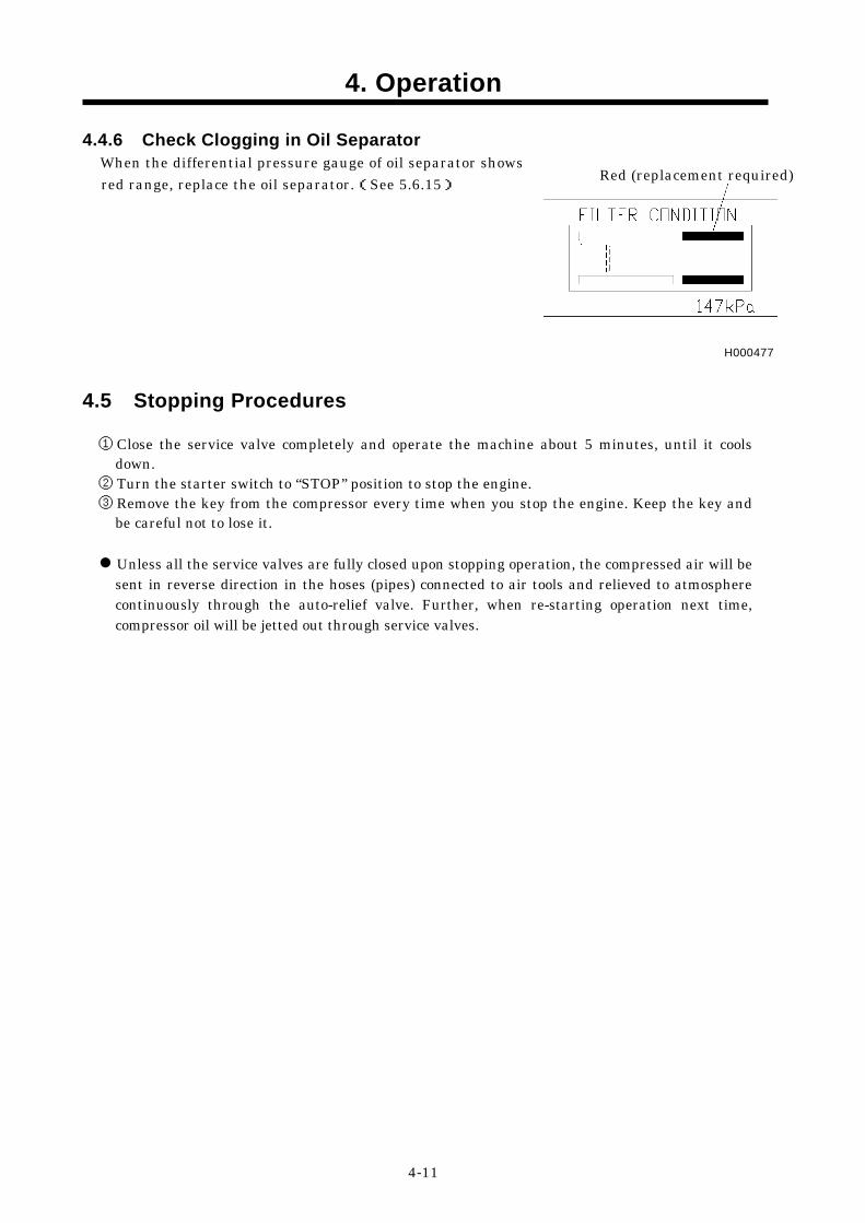
4.4.6 Check Clogging in Oil Separator When the differential pressure gauge of oil separator shows red range, replace the oil separator.(See 5.6.15)
4.5 Stopping Procedures
① Close the service valve completely and operate the machine about 5 minutes, until it cools
down. ② Turn the starter switch to “STOP” position to stop the engine. ③ Remove the key from the compressor every time when you stop the engine. Keep the key and
be careful not to lose it. Unless all the service valves are fully closed upon stopping operation, the compressed air will be sent in reverse direction in the hoses (pipes) connected to air tools and relieved to atmosphere continuously through the auto-relief valve. Further, when re-starting operation next time, compressor oil will be jetted out through service valves.
Red (replacement required)
H000477

5. Periodic Inspection/Maintenance
5-1
5.1 Important Items at Periodic Inspection and Maintenance or after Maintenance
The manual shows proper interval for periodic inspection and maintenance under normally operating conditions. Inspection and maintenance should be performed more often under extremely harsh conditions.
Hang a “Now Checking and under Maintenance” tag Remove the starter key from the starter switch before starting inspection, and hang up a “Now Checking and under Maintenance” tag where it can be easily seen. The checker must keep the key during checking and maintenance. Remove the negative (–) side cable from the battery. If the above procedure is neglected, and another person starts operating the machine during check or maintenance, it could cause serious injury. Use tools appropriate for the inspection and maintenance. Any makeshift or improper tools could cause unexpectedly injury by their slippage.
SY001
For protecting oil separator from fire accident Be sure to perform oil change basically according to the specified interval. But if such oil is found much more contaminated before the interval, change the oil even before the specified period comes. In doing so, replace the oil completely and use our recommended oil. Be sure to perform following periodic inspection and maintenance: 1. Check and change compressor oil 2. Change oil separator Never mix the oil of different brands, or the mixed oil may deteriorate the oil quality.
Waste from machines contains harmful material. Do not dispose of such harmful fluids to the ground, rivers, lakes or ponds, and sea. It contaminates the environment. When draining waste fluid from machines, use leakproof containers to hold such fluids from machine. Be sure to follow the designated regulations when disposing of oil, fuel, coolant, filters, battery and other harmful things.
2
1
A030180

5. Periodic Inspection/Maintenance
5-2
Precautions for check and maintenance Be sure to use recommended fuel, oil, grease, and antifreeze. Do not disassemble or adjust engine, compressor or part(s) for which inspection or maintenance is not referred to in this manual. Use genuine parts for replacement. Any breakdown, caused by using unapproved parts or by wrong handling, will be out of the scope of “WARRANTY”. Keep the electrical components away from water or steam.
5.2 Daily Inspection and Operation Log Be sure to carry out daily inspection every morning before operation. See Chapter 2 “Operation” of the manual for the details of inspection. Pay attention to and carefully observe the following points during daily operation or inspection and maintenance work. If any trouble or abnormality is found, immediately investigate its cause and make repairs. If the cause is unknown or not traceable, or if the trouble involves a part or component not described in the manual, ask your nearest dealer for information.
(a)Controls and instruments function properly. (b)Quantity and any leak of water, fuel, and oil or any
contamination should be checked. (c)Appearance, abnormal noise or excessive heat should be
checked. (d)Loose bolt or nut should be checked. (e)Any damage, wear or shortage of machine components and
parts should be checked. (f)Performance of each part or component should be proper.
Keep the operation log to record constant inspection of each component, so that trouble of the unit
can be easily discovered and preventive measures can be taken. It is very useful to record information such as discharge pressure, oil level, as well as running hour, maintenance items and replenishment of lubricant on a daily maintenance log.
5.3 Inspection on Separator Receiver Tank
Periodic inspection of separator receiver tank Be sure to carry out the following cleaning and inspection of the separator receiver tank at least once every year. (Place to check) (1) Any damage found on the tank. (2) Any excessive wear found to fastening bolts on the cover. (3) Any damage found to pipes and valves etc.
TR0049

5. Periodic Inspection/Maintenance
5-3
5.4 Periodic Inspection List Such items marked ○ shall be carried out by customers. For the following items or clauses marked ●, contact us directly or our distributors because they require expert technical knowledge on them. The following table shows the inspection and maintenance intervals under normal operation conditions. In case the unit is operated under harsh environmental conditions and operation conditions, the intervals should be shortened. ◎Refer to engine operation manual for inspection and maintenance of an engine.
(Unit:Hour)
Maintenance Daily 250 300 500 1,000 2,000 3,000 12,000 Page
Check compressor oil level. ○ 4-4
Drain separator receiver tank. ○ 4-4 Check looseness in pipe connecting part, and wear and tear of pipe. ○ 4-6
Check oil, water, fuel and air leak. ○ 4-10 Check performance of gauge and indication lamps. ○ 4-10 Change compressor oil. ○
○ 5-7
Change compressor oil filter. ○
○ 5-8
Clean strainer in the scavenging orifice. ○ 5-8
Clean and change air filter element. ○ 5-8
Clean outside of the oil cooler. ○ 5-9
Supply grease to trailer spring pin ○ 5-11
Change speed regulator diaphragm. ●
Change unloader regulator o-ring. ●
Change oil separator. ○ 5-11
Change nylon tubes. ●
Change pressure regulator. ●
Check rubber hoses. ●
Check diaphragm of auto-relief valve. ●
Change pressure control valve of o-ring. ●
Change rubber coupling. ●
Com
pres
sor
Change oil seal and bearing ●
First time
First time

5. Periodic Inspection/Maintenance
5-4
(Unit:Hour)
Maintenance Daily 50 250 500 1,000 2,000 3,000 6,000 Page Drain water sedimenter ○ 4-5 Check fuel level ○ 4-5 Check engine oil level. ○ 4-2 Check coolant level. ○ 4-3 Check looseness in pipe connectors, terminals and tear in wiring. ○ 4-6
Check V-belt tension. ○ 4-6 Drain fuel tank ○ 5-9
Change engine oil. ○ ○ 5-5
Change engine oil filter. ○ ○ 5-6
Check battery electrolyte. ○ 5-6 Clean and change air-filter element. ○ 5-8 Change filter inside the fuel air bleeding electromagnetic pump. ○ 5-9
Change fuel filter. ○ 5-9 Clean the strainer provided inside the engine feed pump. ○ 5-12
Change coolant. ○ 5-10 Clean outside of radiator. ○ 5-9 Check rubber hose. ○ 5-12 Clean inside of radiator. ● Clean inside of fuel tank. ● Change radiator hoses. ●
Engi
ne
Change wiring harness. ●
5.5 Periodic Replacement of Parts
Part Name Part Number Quantity Engine oil filter ISUZU 1132402321 1 Compressor oil filter 37438 05601 1
32143 12400 ( inner element.) 1 Air filter element (compressor) 32143 12500 ( outer element.) 1 32143 12600 ( inner element.) 1 Air filter element (engine) 32143 12700 ( outer element.) 1
Fuel filter ISUZU 1132400791 1 Oil separator ass'y“1” 34220 14900 1 Gasket“2” 34235 04400 1 Gasket“3” 34235 04300 1 Electromagnetic pump filter ISUZU 8944370220 1 Fuel feed pump gasket ISUZU 9-0957-2014-0 2
First time
First time

5. Periodic Inspection/Maintenance
5-5
5.6 Maintenance 5.6.1 Change Engine Oil At 50 hours for the first change and at every 500 hours thereafter
Caution in filling or discharging engine oil After stopping the engine, wait for 10 to 20 minutes until the engine oil cools off. Then check the level of the engine oil, or refill or drain the oil. Engine oil is very hot and highly pressurized during or just after the operation. Hot oil could blow out of the tank and can cause scalding.
H990432
Viscosity of engine oil greatly affects startability, performance, oil consumption of the engine, as well
as wear of the moving parts. Choose appropriate oil based upon the table below according to the outside air temperature.
Relation between viscosity (SAE) and temperature
SAE Viscosity number Temperature
10W -22°F to 50°F (-30℃ to 10℃) 30 14°F to 104°F (-10℃ to 40℃)
40 32°F to 122°F ( 0℃ to 50℃)
15W/40 -4° F to 104°F (-20℃ to 40℃)
Be sure to use CD class engine oil or superior class. (Using engine oil with poor quality may shorten the life of the engine).
(Procedure) ① Loosen the drain valve“1”located inside of the frame to
drain out the used oil. ② When the oil is completely drained, close the drain
valve“1” firmly and refill new engine oil through the engine oil filler“2”.
2
How to choose engine oil
A040044 1


5. Periodic Inspection/Maintenance
5-7
5.6.5 Change Compressor Oil
Refilling of compressor oil When you refill the separator receiver tank with compressor oil, stop the engine, and make sure that the pressure gauge indicates 0psi ( 0bar ) and there is no residual pressure in it, and then gradually loosen the oil filler cap for refilling oil. Note residual pressure in the receiver tank could force both extremely hot compressed air and oil to jet out and you may be scalded or seriously injured.
W010
Do not mix compressor oil Be sure to use recommended oil listed below. Viscosity of the oil varies depending on the temperature and other environmental conditions. Select one from the recommended oil listed below.
Maker and Brand of Recommended Oil Maker Brand HULS ANDEROL 3032
MOBIL RARUS SHC 1024 TEXACO SYN-STER DE32 Even continuous oil replenishment cannot improve its deteriorated condition. Be sure to change the oil completely at every scheduled interval. Do not mix it with other brand oil, or it will cause poor performance and shorten the life of the compressor oil. (But fresh compressor oil could accept a mixture of small amount of different brands.) Running the unit with old and deteriorated compressor oil will cause damage to bearings, or serious accident like ignition in a separator receiver tank. Be sure to change the oil completely at every scheduled interval.
(Procedures) ① Remove the oil filler cap“2”of separator receiver tank“1”. ② Open drain valve“3”to discharge waste oil from the tank. ③ In case of replacement, completely discharge all the oil left
in the compressor body, separator receiver tank“1”, pipes and oil cooler. If wasted oil is left in the unit, this residual oil will greatly shorten the life of the newly replenished oil.
④ Be sure to close drain valve“3”after the wasted oil is completely discharged.
⑤ Fill the designated quantity of new oil into the oil filler port. ⑥ After oiling, tighten the cap“2”in its place while paying
attention not to let dust get in the tank. ⑦ Start the engine for a short while, then replenish the oil to
fill shortage. Repeat this procedure for 2 to 3 times to check if the oil level has reached its appropriate point. Be careful not to overfill the oil.
1
2
3
A040045

5. Periodic Inspection/Maintenance
5-8
5.6.6 Change Compressor Oil Filter
At 300 hours for the first change and every 500 hours thereafter
Use our genuine oil filter Poor quality oil filters do not trap dust sufficiently and will cause damage to the bearings in a short period.
(Procedure) ① Use a filter wrench to remove the cartridge“1”. ② Spread thin film of oil on a packing“2”of a new cartridge
“1”and screw it in.(For replacement parts, refer to5.5) ③ After a packing touches the sealing face, tighten it 3/4 or
one time turn, using filter wrench. ④ After installing oil filter, be sure to check for oil leak during
the operation. 5.6.7 Clean Strainer in the Scavenging Orifice
Wash the strainer“1”with diesel fuel, and blow off the “dust” with air.
5.6.8 Change Air Filter Element
Use our genuine part Air filter is an important part which is crucial to machine's performance and life. Be sure to use genuine parts. Even before 500 hours of use, if it is used under harsh conditions, remove the element“1”,“2”,“3”,“4”check and clean it. If it is found difficult to restore it, change it a little earlier. (For replacement parts, refer to 5.5.)
3
(For compressor)
(For engine)
1
2
H000049
A040057
A040046
1
4 2 1


5. Periodic Inspection/Maintenance
5-10
5.6.13 Change Coolant
Taking off the radiator cap Be sure to stop the machine and allow time to cool. Then loosen the radiator cap one notch. After the coolant water is sufficiently cooled and the inner pressure is released, take the cap off. If this procedure is neglected, the inner pressure can blow off the cap. Steam jetting out of the radiator could result in causing scalding. Follow this procedure under all circumstances.
H990432
How to handle LLC (Antifreeze) LLC (Antifreeze) is a toxic material. When a person has drunk LLC (Antifreeze) by accident, make him vomit and see a doctor immediately. When a person gets LLC (Antifreeze) in his eyes, wash the eyes with clean running water and
make him see a doctor immediately. When LLC (Antifreeze) is stored, put it in a container with an indication saying “LLC (Antifreeze)
inside” and seal it up, then keep it in a place away from children. Beware of flames. Follow the designated regulations to dispose of LLC (Antifreeze).
Quality of coolant and antifreeze Use soft water of good quality such as tap water for coolant. When water with dirt, sand, and/or dust contained, or hard water such as well water (ground water) is used, this will cause deposits inside radiator or on cylinder head, and will cause engine overheat due to poor flow of coolant. When replacing coolant, be sure to install a coolant filter and add coolant. When the unit is used in a cold region and possible freezing is expected, it is recommended to use LLC (Antifreeze) for the coolant. Adjust mixing ratio of LLC (Antifreeze) with water according to the temperature. Use LLC (Antifreeze) within the range of its mixing ratio between 35 and 60%. If LLC (Antifreeze) in the water exceeds more than 60%, it may decrease its antifreezing effect.
Reference of LLC (Antifreeze) mixing ratio Temperature Mixing ratio –4°F (–20°C) 35%
–40°F (–40°C) 55%

5. Periodic Inspection/Maintenance
5-11
(Procedure) ① To drain coolant, remove cap“2”of header tank on
radiator“1”top and open the drain valve“3”to drain it.
② Also be sure to drain engine by loosening the drain plug “4”without fail.
③ After completing drainage, close the drain valve“3”and drain plug“4”and then supply coolant through the filler port of the header tank.
④ After coolant is filled up, run unit at unload condition for 2 or 3 minutes and stop it. Then check coolant level. When the level is low, replenish it.
5.6.14 Supply grease to trailer spring pin Supply grease through grease nipples positioned at the bottom. Grease: Chassis grease
5.6.15 Change Oil Separator If even before scheduled interval of 2,000 hours operation, consumption of compressor oil is unusually high. and the differential pressure gauge of the oil separator reaches Red range, change the oil separator. (See 4.4.6) But note that the differential pressure gauge shows correct indication only in full load operation and minimum pressure.
Replacing oil separator ass'y “1”and gasket “2”, “3”.
(For part numbers, refer to 5.5). When replacing oil separator, contact directly us or distributor because it requires expert technical knowledge.
A040047
3
2 1
TR0260B
1
4
A040049-1
2
3


6. Maintenance/Adjustment
6-1
6.1 Maintenance of Battery
Do not connect the cable reversely If a booster cable has to be used or when cables are connected at battery replacement, be careful not to connect (+) and (–) terminals backwards. Such a wrong-connection will cause spark and damage each component.
Handling battery Keep flames away from battery. Battery may generate hydrogen gas and may explode. Therefore, recharging should be done at a well-ventilated
place. Do not spark near the battery nor light a match, nor bring
lit cigarette and match close to the battery. Do not check the battery by short-circuiting the positive
and negative terminals with a metallic piece. Never operate the machine nor charge the batteries with the battery liquid level being kept lower than the "LOWER" level. Continuing operation at this lower level will cause deterioration of such parts as pole plates etc., and also it may cause explosion as well as reduction of battery life. Add distilled water so that the liquid level may reach the middle level between the "UPPER" and "LOWER" level without any delay. Do not charge the frozen battery. Otherwise it may explode. If the battery is frozen, warm it up until the battery temperature becomes 61°F to 86°F (16°C to 30°C). Battery electrolyte is dilute sulfuric acid. In case of mishandling, it could cause skin burning. When you deal with a battery, please be sure to wear protection implements, such as protection glasses and a glove. When such battery electrolyte contacts your clothes or
skin, wash it away with large amount of water immediately. If the battery electrolyte gets into your eyes, wash it away
immediately with plenty of water and see a doctor at once, because it is feared that eyesight might be lost. Dispose of battery, observing local regulations.
D004
W010
TR0093


6. Maintenance/Adjustment
6-3
6.2 Troubleshooting Should any trouble occur during operation, do not leave it. Investigate the cause and take appropriate measures. Read the manual carefully and fully understand what to do in case of trouble. The better you understand the construction and function of the unit, the faster you can find a problem and solution. This chapter describes the state, cause and countermeasures of important troubles in detail:
Symptom Cause Countermeasures
Low starter revolution speed.
(1) Battery malfunction. Check battery→ Charge, change
Starter rotates but engine does not start.
(1) Fuel filter clogging. (2) Malfunction of fuel cut motor
stopper. (3) No fuel.
Disassemble, clean, and change Check fuse Change motor stopper Check connector Replenish fuel
Discharge air pressure does not reach 100psi (6.9bar).
(1) Pressure regulator insufficient adjustment.
(2) Starting unloader valve is left at its start position.
Re-adjust (Fasten) Place it at “RUN” position
Engine does not reach its maximum speed.
(1) Improper length in speed regulator rod.
(2) Unloader orifice clogging. (3) Faulty speed regulator. (4) Engine trouble. (5) Fuel filter clogging.
Re-adjust Disassemble/Clean Disassemble/Check Call your nearest dealer Disassemble/Change
Revolution drops before discharge air pressure reaches 100psi (6.9bar).
(1) Pressure regulator insufficient adjustment.
(2) Trouble of pressure regulator. (3) Unloader orifice clogging.
Re-adjust (Fasten) Change Disassemble/Check
Engine does not reach minimum revolution at unload.
(1) Improper length in speed regulator rod.
(2) Faulty speed regulator.
Re-adjust Disassemble/Check
Safety valve relieves at unload.
(1) Pressure regulator insufficient adjustment.
(2) Speed regulator diaphragm damaged.
(3) Unloader valve damaged and seat malfunction.
(4) Faulty safety valve. (5) Improper length of speed
regulator rod
Re-adjust (loosen) Change Change Change Re-adjust (elongate)
Oil mixes in Air. (Poor oil separation)
(1) Scavenging orifice strainer clogging.
(2) Low discharge pressure. (3) Oil separator deteriorated.
Disassemble/Clean Disassemble/pressure Control valve/check Disassemble/Change
Insufficient free air delivery.
(1) Air filter element clogging. (2) Unloader valve cannot fully
open. (3) Engine does not reach rated
speed.
Clean element or change Call your nearest dealer

6. Maintenance/Adjustment
6-4
Symptom Cause Countermeasures
Engine oil pressure lamp goes on.
(1) Engine oil shortage. (2) Engine oil filter clogging. (3) Malfunction of engine oil pump (4) Faulty oil pressure switch. (5) Loosened or disconnected
wiring or connector.
Replenish oil Change Change Change Check/Fasten
Coolant temp. lamp goes on.
(1) Radiator clogging. (2) Faulty thermostat. (3) Faulty coolant temp. switch. (4) Low coolant level. (5) Fan belt slippage. (6) Loose wiring, connectors and desconnection
Clean Change Change Replenish Re-adjust tension Check/retighten
Discharge air temp. lamp goes on.
(1) Oil cooler clogging. (2) Oil filter clogging. (3) Faulty discharged air temp.
switch. (4) Loose wiring connectors and
disconnection. (5) Slippage of fan belt. (6) Shortage of compressor oil. (7) Malfunction of by-pass valve.
Clean Change Check/inspect Check and retighten Re-adjust tension Replenish oil Check/change
Engine speed down lamp goes on.
(1) Speed regulator insufficient adjustment.
(2) Trouble of controller.
Re-adjust Change
Fuel residual level lamp goes on.
(1) Fuel runs short. (2) Malfunction of fuel oil level
drop sending unit (3) Loose wiring connectors and
disconnection
Refueling Check/change Check and retighten
Contact your nearest dealer if you find it difficult to repair by yourselves. Refer to the engine operation manual for trouble concerning the engine.

7. Storage of the Unit
7-1
7.1 Preparation for Long-term Storage
When the unit is to be kept unused in storage for a long time, be sure to follow the preparations below and put the unit in a dry and less dusty place.
Put the unit in a temporary cabin if it is stored outside. Avoid leaving the unit outside with a sheet cover directly on the paint for a long time, or this will cause rust to the unit. Perform the following treatments at least once every three months.
(Procedure) ① Drain existing lubricant from the engine oil pan. Pour new lubricant in the engine to clean its
inside. After running it for a while, drain it again. ② Spread lubricant on moving parts like speed regulator and rod end, beforehand. ③ Completely charge the battery and disconnect grounding wires. Remove the battery from the unit,
if possible, and store it in a dry place. (Charge the battery at least once every month.) ④ Drain coolant and fuel from the unit. ⑤ Seal the engine, air-intake port and other openings like the muffler with a vinyl sheet, packing
tape, etc., to prevent moisture and dust from getting in the unit. ⑥ Be sure to repair any trouble and maintain the unit so that it will be ready for the next
operation.

8. Specifications
8-1
8.1 Specifications Length in.(mm) 142(3,600) Type Single-stage oil cooled,
screw type compressor Length (draw-bar excluded) in.(mm) 95 (2,445) Free air delivery cfm(m3/min) 400 (11.3) Width in.(mm) 78(1,975) Working pressure psi(bar) 100 (6.9)
Height in.(mm) 68(1,720) Maximum pressure psi(bar) 150 (10.3)
Dry weight lb(kg) 4,004 (1,820) Weight in operating condition lb(kg) 4,488 (2,020)
Lubricating system Forced Lubrication by
compressed pressure.
Fuel tank capacity gal.(L) 43.6(165) Driving system Direct driving with
rubber coupling.
Receiver tank capacity cu in.(m3) 5,980 (0.098)
Com
pres
sor
Lubrication oil capacity gal.(L) 13.5 (51)
Model ISUZU DD-4BG1-T Type
4-cycle, water-cooled, direct injection type with turbo charged
Number of cylinders, bore×stroke
in. (mm)
4-4.1×4.9 (4-105×125)
Total displacement cu in.(L) 264 (4.329)
Rated output hp/rpm (kW/min-1)
108.5/2,400 (80.9/2,400)
Lubricating oil capacity gal.(L) 3.4 (13)
Coolant capacity (including radiator) gal.(L) 3.4 (13)
Engi
ne
Battery 80D26R × 2 8.2 Outline drawing
A040048


10. Piping Diagram
10-1
A040051

39600 50921PRINTED IN JAPAN 2004. 5
HOKUETSU INDUSTRIES CO., LTD.
12TH FLOOR SHINJUKU SAN-EI BLDG, 22-2 NISHI-SHINJUKU 1-CHOME,SHINJUKU-KU TOKYO 160-0023 JAPAN TEL:TOKYO 813(3348)7281 FAX:TOKYO 813(3348)7289 URL:http//www.airman.co.jp