Air Charger Sulfur Filter 5900e-AIR Installation & Start ... · Air Charger Sulfur Filter 5900e-AIR...
19
Air Charger Sulfur Filter 5900e-AIR Installation & Start-Up Guide Thank you for purchasing a Clean Water System! With proper installation and a little routine maintenance your system will be providing sulfur odor-free water for many years. Please review this start-up guide entirely before beginning to install your system and follow the steps outlined for best results. MEDIA CONTAINS DUST. USE PAPER MASK AND VENTILATE TO AVOID BREATHING DUST. 2806-A Soquel Ave Santa Cruz CA 95062 For assistance call: 1-831-462-8500 Email us: [email protected] More information online: www.cleanwaterstore.com Clean Water Made Easy www.cleanwaterstore.com
Transcript of Air Charger Sulfur Filter 5900e-AIR Installation & Start ... · Air Charger Sulfur Filter 5900e-AIR...
Air Charger Sulfur Filter 5900e-AIR Installation & Startup Guide
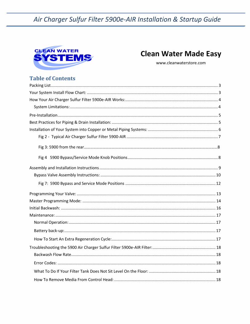
Air Charger Sulfur Filter 5900e-AIR Installation &
Start-Up Guide
Thank you for purchasing a Clean Water System! With proper installation and a little routine maintenance your system will be providing sulfur odor-free water for many years. Please review this start-up guide entirely before beginning to install your system and follow the steps outlined for best results.
MEDIA CONTAINS DUST. USE PAPER MASK AND VENTILATE TO AVOID BREATHING DUST.
2806-A Soquel Ave Santa Cruz CA 95062
For assistance call: 1-831-462-8500
Email us: [email protected]
More information online: www.cleanwaterstore.com
Clean Water Made Easy
www.cleanwaterstore.com
Air Charger Sulfur Filter 5900e-AIR Installation & Startup Guide
Table of Contents
Packing List .................................................................................................................................................... 3
Your System Install Flow Chart: .................................................................................................................... 3
How Your Air Charger Sulfur Filter 5900e-AIR Works: .................................................................................. 4
System Limitations: ................................................................................................................................... 4
Pre-Installation .............................................................................................................................................. 5
Best Practices for Piping & Drain Installation: .............................................................................................. 5
Installation of Your System into Copper or Metal Piping Systems: .............................................................. 6
Fig 2 - Typical Air Charger Sulfur Filter 5900-AIR ................................................................................. 7
Fig 3: 5900 from the rear…………………………………………………………………………………………………………………8
Fig 4 5900 Bypass/Service Mode Knob Positions ................................................................................ 8
Assembly and Installation Instructions ......................................................................................................... 9
Bypass Valve Assembly Instructions: ...................................................................................................... 10
Fig 7: 5900 Bypass and Service Mode Positions ................................................................................ 12
Programming Your Valve: ........................................................................................................................... 13
Master Programming Mode: ...................................................................................................................... 14
Initial Backwash: ......................................................................................................................................... 16
Maintenance: .............................................................................................................................................. 17
Normal Operation: .................................................................................................................................. 17
Battery back-up: ...................................................................................................................................... 17
How To Start An Extra Regeneration Cycle: ............................................................................................ 17
Troubleshooting the 5900 Air Charger Sulfur Filter 5900e-AIR Filter: ........................................................ 18
Backwash Flow Rate ................................................................................................................................ 18
Error Codes: ............................................................................................................................................ 18
What To Do If Your Filter Tank Does Not Sit Level On the Floor: ........................................................... 18
How To Remove Media From Control Head: .......................................................................................... 18
Clean Water Made Easy
www.cleanwaterstore.com
Air Charger Sulfur Filter 5900e-AIR Installation & Startup Guide
Packing List:
1.5 Cubic Foot Size System Air Charger Sulfur Filter 5900e-AIR control valve w/ bypass assembly and pipe connector kit (1” or 3/4”) 10” x 54” standard filter tank with distributor tube Blue media funnel for adding Air Charger Sulfur Filter media 1.5 cubic feet of Jacobi Catalytic Carbon media 16 lbs. filter gravel
2.0 Cubic Foot Size System Air Charger Sulfur Filter 5900e-AIR control valve w/ bypass assembly and pipe connector kit (1” or 3/4”) 12” x 52” standard filter tank with distributor tube Blue media funnel for adding Air Charger Sulfur Filter media 2.0 cubic feet of Jacobi Catalytic Carbon media 20 lbs. filter gravel
2.5 Cubic Foot Size System Air Charger Sulfur Filter 5900e-AIR control valve w/ bypass assembly and pipe connector kit (1” or 3/4”) 13” x 54” standard filter tank with distributor tube Blue media funnel for adding Air Charger Sulfur Filter media 2.5 cubic feet of Jacobi Catalytic Carbon media 20 lbs. filter gravel
All systems also include a Power Supply, an Air Draw Fitting, a ½” mpt X 5/8” ID Barb Fitting, and a 5 and
7 gpm Drain Line Flow Control (DLFC) Button.
Your System Install Flow Chart: 1) Verify that you have received all parts for your system and there are no damaged or missing
parts.
2) Build the filter vessel, and fill with water and 1-2 cups of chlorine bleach. The longer it soaks
while you are doing everything else, the better. Build the filter near to where it goes, it will be
very heavy when you are done.
3) Make the plumbing connections from your existing system to the bypass assembly, installing
extra valves, unions, pressure gauges or hose bibs as needed.
4) Attach the control head to the tank, and to the bypass assembly.
5) Install the Drain Line tubing and the DLFC
6) Plug in the power supply and program the valve.
Air Charger Sulfur Filter 5900e-AIR Installation & Startup Guide
Page 4 www.cleanwaterstore.com Rev 082616
7) Do the Initial Backwash and rinse of the media with the water turned off to the house, after the
iron filter.
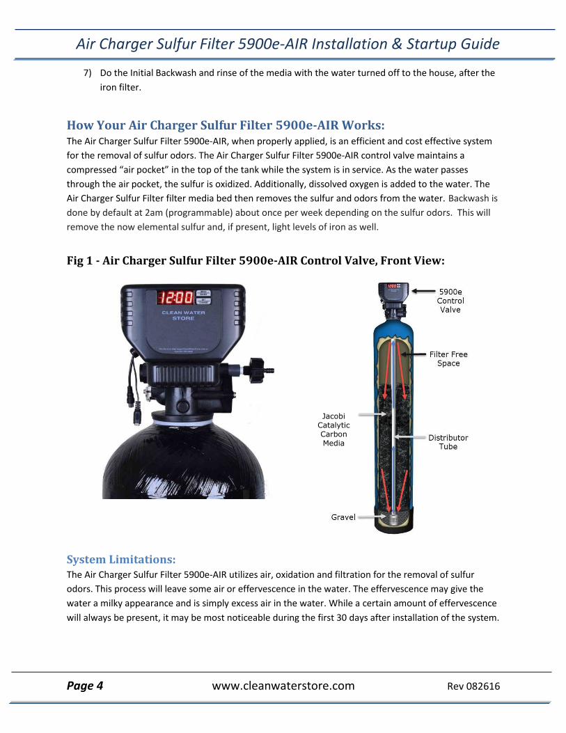
How Your Air Charger Sulfur Filter 5900e-AIR Works: The Air Charger Sulfur Filter 5900e-AIR, when properly applied, is an efficient and cost effective system
for the removal of sulfur odors. The Air Charger Sulfur Filter 5900e-AIR control valve maintains a
compressed “air pocket” in the top of the tank while the system is in service. As the water passes
through the air pocket, the sulfur is oxidized. Additionally, dissolved oxygen is added to the water. The
Air Charger Sulfur Filter filter media bed then removes the sulfur and odors from the water. Backwash is
done by default at 2am (programmable) about once per week depending on the sulfur odors. This will
remove the now elemental sulfur and, if present, light levels of iron as well.
Fig 1 - Air Charger Sulfur Filter 5900e-AIR Control Valve, Front View:
System Limitations: The Air Charger Sulfur Filter 5900e-AIR utilizes air, oxidation and filtration for the removal of sulfur
odors. This process will leave some air or effervescence in the water. The effervescence may give the
water a milky appearance and is simply excess air in the water. While a certain amount of effervescence
will always be present, it may be most noticeable during the first 30 days after installation of the system.
Jacobi Catalytic Carbon Media
Air Charger Sulfur Filter 5900e-AIR Installation & Startup Guide
Page 5 www.cleanwaterstore.com Rev 082616
Pre-Installation 1. Review your packing list and make sure you have received all the parts before beginning
installation.
2. If you are going to be turning off the water to the house and you have an electric water heater,
shut off the power to the water heater before beginning installation in case water heater is
accidentally drained.
3. Pick a suitable location for your filter system on a dry level spot where it won’t be exposed to
freezing temperatures. A minimum of 30 PSI is required. Maximum pressure is 90 PSI.
4. Get all of your plumbing parts together before beginning installation. Installation typically takes
3 to 5 hours. However, after installation the Air Charger Sulfur Filter 5900e-AIR must be allowed
to run through one complete backwash and rinse cycle.
5. After the system is installed and running, your water may be discolored, or full of sediment or
rust, particularly if this is older or corroded piping. This typically clears up over a day or two.
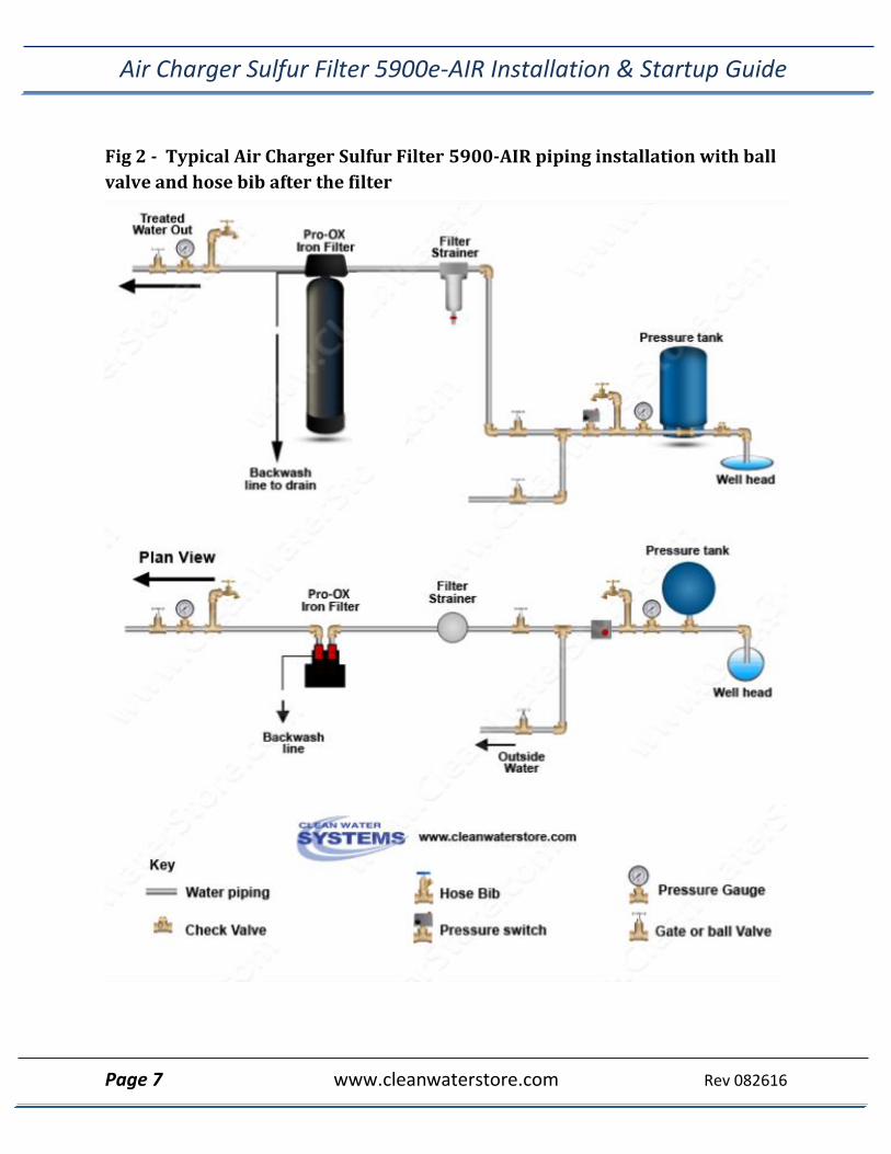
Best Practices for Piping & Drain Installation: 1. See typical installation on page 6 (Fig 2). The Air Charger Sulfur Filter 5900e-AIR is installed
after the pressure tank.
2. Make sure to connect the IN pipe to the Air Charger Sulfur Filter 5900e-AIR inlet and the OUT
pipe to the outlet (see Fig 3). As you face the Air Charger Sulfur Filter 5900e-AIR control from
the front, the water enters on the right and exits on the left. From the back (see Fig 3) the water
enters on the left. The inlet and outlet are attached to the bypass valve, which is marked with
arrows as well.
3. Make sure there is a working gate or ball valve before the Air Charger Sulfur Filter 5900e-AIR
and also one after as shown in Fig 2. The pressure gauges are optional and perhaps not
necessary but a hose bib (which is a faucet that you can attach a garden hose to) is strongly
recommended after the Air Charger Sulfur Filter 5900e-AIR and before the second ball valve.
This makes it easy to rinse your new Air Charger Sulfur Filter 5900e-AIR on start-up and gives
you a place to test the water before it enters your household plumbing.
4. If you will be using copper piping, do not sweat the copper pipe directly on to the Air Charger
Sulfur Filter 5900e-AIR control valve. Avoid heating up the Air Charger Sulfur Filter 5900e-AIR
control valve plastic with the torch.
5. If you have copper pipe before the Air Charger Sulfur Filter 5900e-AIR and it is too difficult to
change out, you may still experience some copper staining of fixtures and have a copper residual
Air Charger Sulfur Filter 5900e-AIR Installation & Startup Guide
Page 6 www.cleanwaterstore.com Rev 082616
in the water because this section of pipe will still have acidic water flowing through it. We
recommend PEX or PVC pipe up to the Air Charger Sulfur Filter 5900e-AIR and then copper after
it, if you have copper plumbing.
6. You do not need unions to install your Air Charger Sulfur Filter 5900e-AIR control valve. If you
need to remove it, the Air Charger Sulfur Filter 5900e-AIR has quick-release couplings that make
it easy to put the Air Charger Sulfur Filter 5900e-AIR on by-pass and remove the filter system
from the piping.
7. The drain line tubing (not supplied) is connected to a drain from the drain outlet using flexible
½” ID tubing. Note that the drain can run up above the Air Charger Sulfur Filter 5900e-AIR
control and into a drain, it does not have to drain down, as the filter backwashes under line
pressure from your well pump. Most plumbing codes require an air-gap connection, so that if
your sewer or septic tank backs up, it cannot cross connect with the drain tubing.
Installation of Your System into Copper or Metal Piping Systems:
If your new filter system is to be installed in a metal (conductive) plumbing system, i.e. copper or
galvanized steel pipe, the plastic components of the system will interrupt the electrical continuity of
the plumbing system.
As a result any stray currents from improperly grounded appliances downstream or potential
galvanic activity in the plumbing system can no longer ground through the contiguous metal
plumbing.
Some homes may have been built in accordance with building codes, which encouraged the
grounding of electrical appliances through the plumbing system.
Consequently, the installation of a bypass consisting of the same material as the existing plumbing,
or a grounded "jumper wire" bridging the equipment and reestablishing the contiguous conductive
nature of the plumbing system must be installed prior to your systems use.
This is simple and easy step to take if you are installing your water treatment system into copper
piping. A simple ground jumper wire with a pipe clamp can be purchased at any Home Center, or
hardware store, etc. for a few dollars.
Air Charger Sulfur Filter 5900e-AIR Installation & Startup Guide
Page 7 www.cleanwaterstore.com Rev 082616
Fig 2 - Typical Air Charger Sulfur Filter 5900-AIR piping installation with ball
valve and hose bib after the filter
Air Charger Sulfur Filter 5900e-AIR Installation & Startup Guide
Page 8 www.cleanwaterstore.com Rev 082616
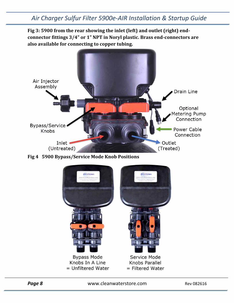
Fig 3: 5900 from the rear showing the inlet (left) and outlet (right) end-
connector fittings 3/4” or 1” NPT in Noryl plastic. Brass end-connectors are
also available for connecting to copper tubing.
Fig 4 5900 Bypass/Service Mode Knob Positions
Air Charger Sulfur Filter 5900e-AIR Installation & Startup Guide
Page 9 www.cleanwaterstore.com Rev 082616
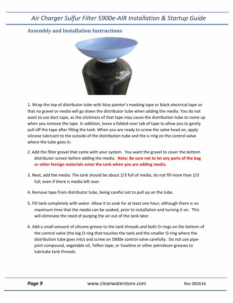
Assembly and Installation Instructions
1. Wrap the top of distributor tube with blue painter’s masking tape or black electrical tape so
that no gravel or media will go down the distributor tube when adding the media. You do not
want to use duct tape, as the stickiness of that tape may cause the distribution tube to come up
when you remove the tape. In addition, leave a folded-over tab of tape to allow you to gently
pull off the tape after filling the tank. When you are ready to screw the valve head on, apply
silicone lubricant to the outside of the distribution tube and the o-ring on the control valve
where the tube goes in.
2. Add the filter gravel that came with your system. You want the gravel to cover the bottom
distributor screen before adding the media. Note: Be sure not to let any parts of the bag
or other foreign materials enter the tank when you are adding media.
3. Next, add the media. The tank should be about 2/3 full of media, do not fill more than 2/3
full, even if there is media left over.
4. Remove tape from distributor tube, being careful not to pull up on the tube.
5. Fill tank completely with water. Allow it to soak for at least one hour, although there is no
maximum time that the media can be soaked, prior to installation and turning it on. This
will eliminate the need of purging the air out of the tank later.
6. Add a small amount of silicone grease to the tank threads and both O-rings on the bottom of
the control valve (the big O-ring that touches the tank and the smaller O-ring where the
distribution tube goes into) and screw on 5900e control valve carefully. Do not use pipe-
joint compound, vegetable oil, Teflon tape, or Vaseline or other petroleum greases to
lubricate tank threads.
Air Charger Sulfur Filter 5900e-AIR Installation & Startup Guide
Page 10 www.cleanwaterstore.com Rev 082616
8. Note regarding Teflon tape and pipe sealants: It is okay to use Teflon tape and pipe
sealant on the water pipe connector threads, where you attach your pipes or plumbing
to the 5900e control valve. DO NOT USE any Teflon tapes or pipe joint compound on
the tank itself or on the threads where the Sulfur 5900e-AIR threads into the tanks.
Also note that when installing the Sulfur 5900e-AIR valve on to the top of the filter tank,
do not over-tighten. Tighten by hand; there is no need for a pipe wrench or other
wrench.
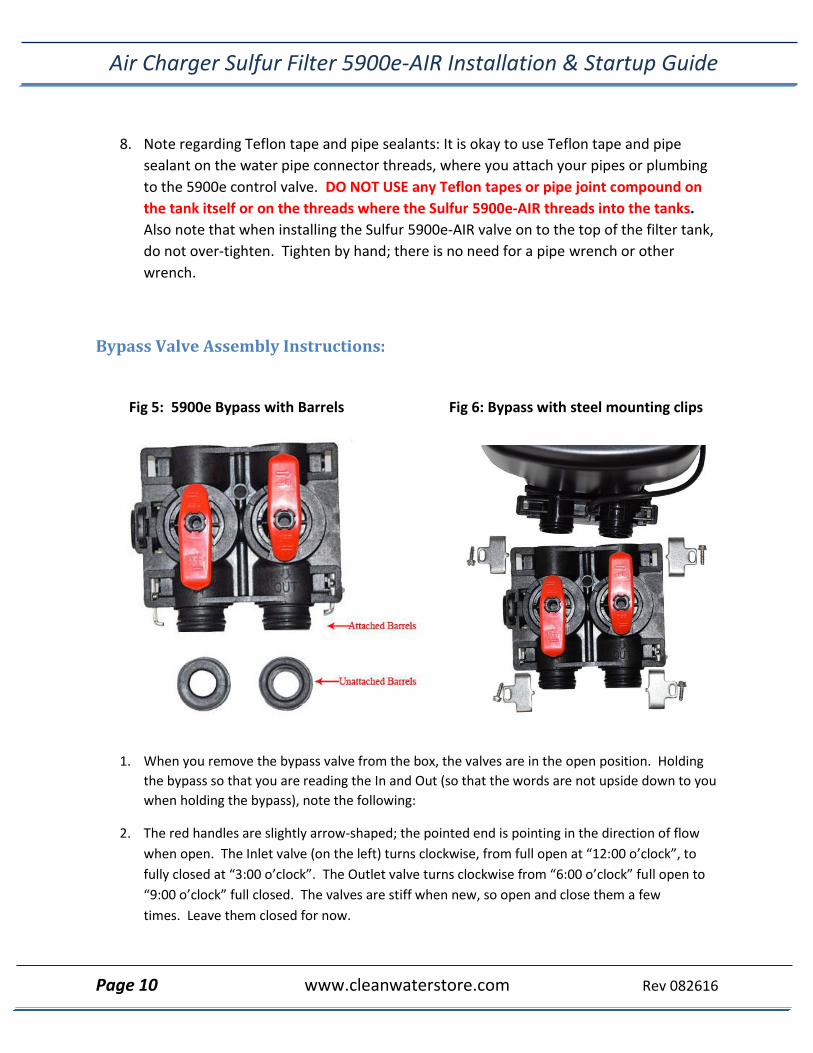
Bypass Valve Assembly Instructions:
Fig 5: 5900e Bypass with Barrels Fig 6: Bypass with steel mounting clips
1. When you remove the bypass valve from the box, the valves are in the open position. Holding
the bypass so that you are reading the In and Out (so that the words are not upside down to you
when holding the bypass), note the following:
2. The red handles are slightly arrow-shaped; the pointed end is pointing in the direction of flow
when open. The Inlet valve (on the left) turns clockwise, from full open at “12:00 o’clock”, to
fully closed at “3:00 o’clock”. The Outlet valve turns clockwise from “6:00 o’clock” full open to
“9:00 o’clock” full closed. The valves are stiff when new, so open and close them a few
times. Leave them closed for now.
Air Charger Sulfur Filter 5900e-AIR Installation & Startup Guide
Page 11 www.cleanwaterstore.com Rev 082616
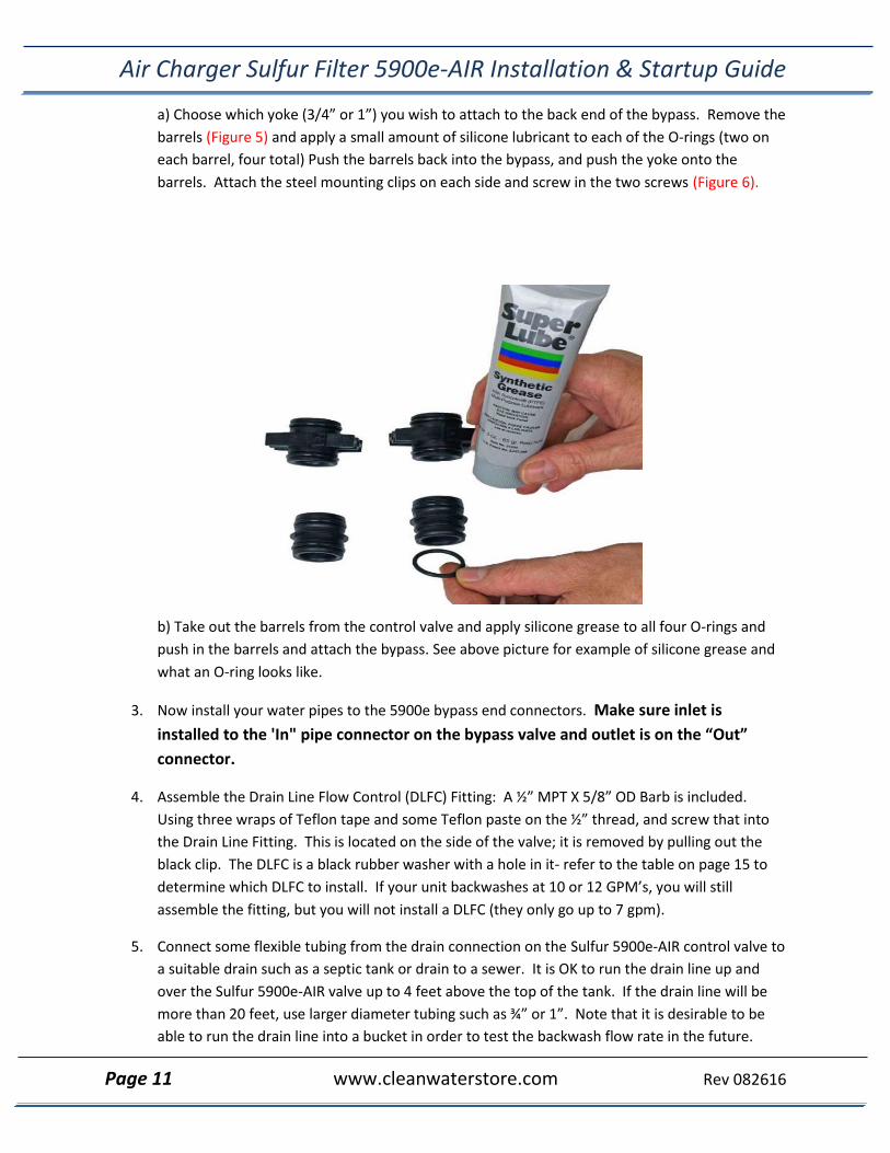
a) Choose which yoke (3/4” or 1”) you wish to attach to the back end of the bypass. Remove the
barrels (Figure 5) and apply a small amount of silicone lubricant to each of the O-rings (two on
each barrel, four total) Push the barrels back into the bypass, and push the yoke onto the
barrels. Attach the steel mounting clips on each side and screw in the two screws (Figure 6).
b) Take out the barrels from the control valve and apply silicone grease to all four O-rings and
push in the barrels and attach the bypass. See above picture for example of silicone grease and
what an O-ring looks like.
3. Now install your water pipes to the 5900e bypass end connectors. Make sure inlet is
installed to the 'In" pipe connector on the bypass valve and outlet is on the “Out”
connector.
4. Assemble the Drain Line Flow Control (DLFC) Fitting: A ½” MPT X 5/8” OD Barb is included.
Using three wraps of Teflon tape and some Teflon paste on the ½” thread, and screw that into
the Drain Line Fitting. This is located on the side of the valve; it is removed by pulling out the
black clip. The DLFC is a black rubber washer with a hole in it- refer to the table on page 15 to
determine which DLFC to install. If your unit backwashes at 10 or 12 GPM’s, you will still
assemble the fitting, but you will not install a DLFC (they only go up to 7 gpm).
5. Connect some flexible tubing from the drain connection on the Sulfur 5900e-AIR control valve to
a suitable drain such as a septic tank or drain to a sewer. It is OK to run the drain line up and
over the Sulfur 5900e-AIR valve up to 4 feet above the top of the tank. If the drain line will be
more than 20 feet, use larger diameter tubing such as ¾” or 1”. Note that it is desirable to be
able to run the drain line into a bucket in order to test the backwash flow rate in the future.
Air Charger Sulfur Filter 5900e-AIR Installation & Startup Guide
Page 12 www.cleanwaterstore.com Rev 082616
This is why hard piping the drain line is discouraged: however, if you do use hard PVC piping for
the drain line, and you are able to remove the hard PVC drain piping and attach flexible tubing
should you ever desire for testing purposes, it is OK to use rigid PVC pipe for the drain. Make
sure the drain tubing is firmly clamped to the barbed fitting with a hose clamp to prevent leaks.
6. Next, you will need to program the system to work as a Sulfur 5900e-AIR Filter. There are a few
settings that must be changed before the system can be put into service. Plug in the control
valve and continue on to the next page to begin the programming instructions.
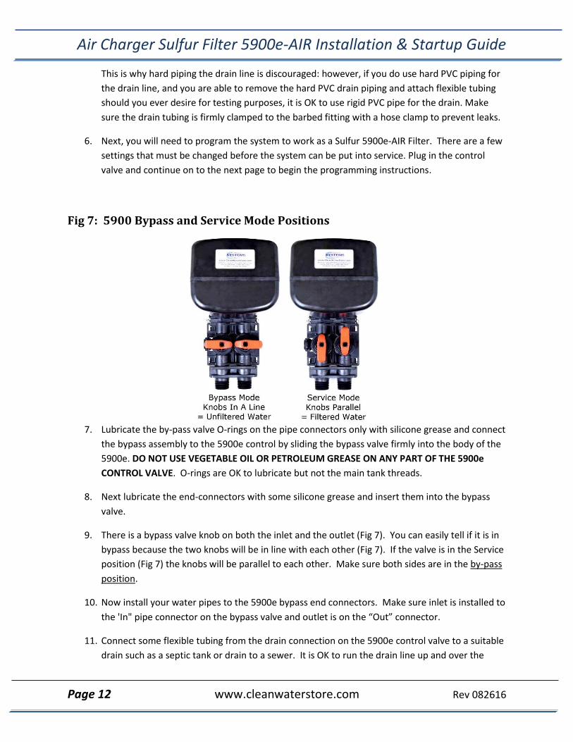
Fig 7: 5900 Bypass and Service Mode Positions
7. Lubricate the by-pass valve O-rings on the pipe connectors only with silicone grease and connect
the bypass assembly to the 5900e control by sliding the bypass valve firmly into the body of the
5900e. DO NOT USE VEGETABLE OIL OR PETROLEUM GREASE ON ANY PART OF THE 5900e
CONTROL VALVE. O-rings are OK to lubricate but not the main tank threads.
8. Next lubricate the end-connectors with some silicone grease and insert them into the bypass
valve.
9. There is a bypass valve knob on both the inlet and the outlet (Fig 7). You can easily tell if it is in
bypass because the two knobs will be in line with each other (Fig 7). If the valve is in the Service
position (Fig 7) the knobs will be parallel to each other. Make sure both sides are in the by-pass
position.
10. Now install your water pipes to the 5900e bypass end connectors. Make sure inlet is installed to
the 'In" pipe connector on the bypass valve and outlet is on the “Out” connector.
11. Connect some flexible tubing from the drain connection on the 5900e control valve to a suitable
drain such as a septic tank or drain to a sewer. It is OK to run the drain line up and over the
Air Charger Sulfur Filter 5900e-AIR Installation & Startup Guide
Page 13 www.cleanwaterstore.com Rev 082616
5900 Air Charger Sulfur Filter 5900e-AIR up to 4 feet above the top of the tank. If the drain line
will be more than 20 feet, use larger diameter tubing such as ¾” or 1”. Note that it is desirable
to be able to run the drain line into a bucket in order to test the backwash flow rate in the
future. This is why hard piping the drain line is discouraged: however, if you do use hard PVC
piping for the drain line, and you are able to remove the hard PVC drain piping and attach
flexible tubing should you ever desire for testing purposes, it is OK to use rigid PVC pipe for the
drain. Make sure the drain tubing is firmly clamped to the barbed fitting with a hose clamp to
prevent leaks.
12. Next, you will need to program the system to work as an Air Charger Sulfur Filter 5900e-AIR
Filter. There are a few settings that must be changed before the system can be put into service.
Plug in the control valve and continue on to begin the programming instructions.
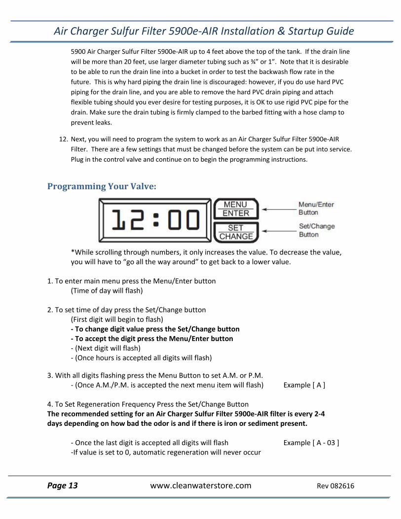
Programming Your Valve:
*While scrolling through numbers, it only increases the value. To decrease the value, you will have to “go all the way around” to get back to a lower value.
1. To enter main menu press the Menu/Enter button
(Time of day will flash) 2. To set time of day press the Set/Change button
(First digit will begin to flash) - To change digit value press the Set/Change button - To accept the digit press the Menu/Enter button - (Next digit will flash) - (Once hours is accepted all digits will flash)
3. With all digits flashing press the Menu Button to set A.M. or P.M. - (Once A.M./P.M. is accepted the next menu item will flash) Example [ A ]
4. To Set Regeneration Frequency Press the Set/Change Button The recommended setting for an Air Charger Sulfur Filter 5900e-AIR filter is every 2-4 days depending on how bad the odor is and if there is iron or sediment present.
- Once the last digit is accepted all digits will flash Example [ A - 03 ] -If value is set to 0, automatic regeneration will never occur
Air Charger Sulfur Filter 5900e-AIR Installation & Startup Guide
Page 14 www.cleanwaterstore.com Rev 082616
5. To Set the Number of Days between Air-Draw Cycles (d) Press the Set/Change Button
1) Set to 1 day, to regenerate the system with new air daily. Example [ d - 01] 2) During this process, the valve will use a little bit of water to create suction in order to regenerate the air, and will make some noise during this cycle. However, the valve will still backwash on the days that you have programmed it to. 2) If Value Set to 0, Air-Draw is Turned Off, but an Air Cycle will still be Completed when a Regeneration Cycle Occurs. If the Number of Days between Air-Draw Cycles is set to a Higher Number of Days than the Number of Days between Regeneration Cycles, it will have no effect.
6. To exit menu press the Menu/Enter button Note: If no buttons are pressed for 60 seconds or longer the menu will automatically be exited.
Next you will need to set the Master Programming to be used as an Air Charger Sulfur Filter
5900e-AIR filter, continue on to the Master Programming to finish the programming
instructions.
Master Programming Mode: Entering Master Programming Mode
-To enter Master Programming Mode press and hold both buttons for 5 seconds. 1. Regeneration Time (r)
Press the Menu/Enter Button. The next display viewed is the option setting for Regeneration Time. It is identified by the letter ‘r’ in the left digit. Set the desired time of day that a regeneration may occur, if required. We recommend setting the system to backwash at 2 AM, or at any time that it is unlikely that any water will be used. The first digit(s) indicates the Hour and the other digit indicates A.M. or P.M..
Example: 2 A.M. regeneration time - [ r 2A ] (factory setting)
3. Regeneration Cycle Step Programming (2)(3)(4)(5) Step 1, the air release, is not programmable, and therefore will not be displayed for programming. Each display is used to set the duration time in minutes for that specific step in a regeneration cycle. A step # will turn on for the regeneration cycle step being programmed. Regeneration steps are skipped by setting the display to 0 as shown below: Examples: Regeneration Cycle Step #2 - 10 minutes - [ 2 - 10 ] Regeneration Cycle Step #3 - skipped - [ 3 - 0 ] Set each step according to the values below, appropriate for an Air Charger Sulfur Filter 5900e-AIR filter:
Air Charger Sulfur Filter 5900e-AIR Installation & Startup Guide
Page 15 www.cleanwaterstore.com Rev 082616
1 Not Programmable. This is the Air Release cycle. [ Not Displayed ]
2 10 minutes. This is the Backwash cycle. [ 2 - 10 ]
3 0 minutes. This is the Brine Draw cycle, not used on your valve. [ 3 - 0 ]
4 12 minutes. This is the Air-Draw cycle [ 4 – 12 ]
5 6 minutes. This is the Rapid Rinse cycle. [ 5 - 6 ]
bE This menu option is for process control applications not used on your Valve.
It will say either 0 or 1, and you do not need to change it.
bttPP This menu option goes with the above, it is not used. It will briefly display 1234 and then
the digital display will return to Service Mode.
Pressing and holding the Menu/Enter button will also access some options: Note that these options only work with a flow sensor, and that this option is unavailable on the AIR valve. Flo- this is the flow rate, if water is running, it will display the volume, in gallons per minute. Gt r- This the total # of gallons that has gone through the filter. g tot- this is the same as the previous. rC r- number of regeneration done. rC- the same. gPdL- shows how many gallons used each day. Gbrl- is the gallons used between regenerations. PfDL- This shows the peak, or highest flow rate that has passed through the filter in the last 24 hours. If you “get stuck” in these options, keep pressing the Menu/Enter button until you have returned to the service screen.
Note on Air-Draw Cycle (5): The longer the unit is set to remain in the air-draw cycle (5), the more air is drawn into the system. A default setting of 12 minutes draws air down to the level of a normal media bed height and then returns the unit to the home display. If the system needs more air, increase the time setting for step (5) or change the number of days between air-draw cycles to 2-3 days (or lower than your current setting). There is no way to view the number of days until the next air draw will take place.
Exiting the Master Programming Mode Press the Menu/Enter Button until all steps have been viewed. The Program Mode will be exited and normal operation resumed. If no buttons are pressed for 60 seconds or longer in Master Programming Mode it will be exited automatically.
Lastly, you will need to perform an initial backwash to finish setting up the filter and getting it ready for
use, continue on to the next page.
Air Charger Sulfur Filter 5900e-AIR Installation & Startup Guide
Page 16 www.cleanwaterstore.com Rev 082616
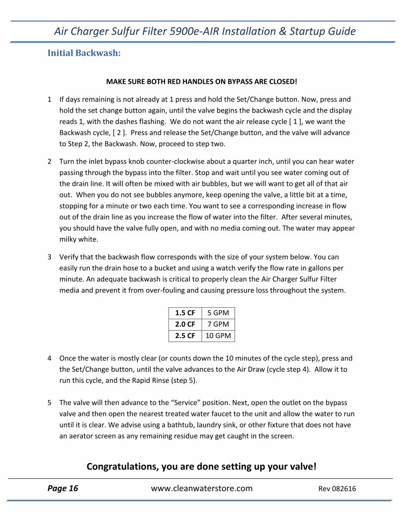
Initial Backwash:
MAKE SURE BOTH RED HANDLES ON BYPASS ARE CLOSED!
1 If days remaining is not already at 1 press and hold the Set/Change button. Now, press and
hold the set change button again, until the valve begins the backwash cycle and the display
reads 1, with the dashes flashing. We do not want the air release cycle [ 1 ], we want the
Backwash cycle, [ 2 ]. Press and release the Set/Change button, and the valve will advance
to Step 2, the Backwash. Now, proceed to step two.
2 Turn the inlet bypass knob counter-clockwise about a quarter inch, until you can hear water
passing through the bypass into the filter. Stop and wait until you see water coming out of
the drain line. It will often be mixed with air bubbles, but we will want to get all of that air
out. When you do not see bubbles anymore, keep opening the valve, a little bit at a time,
stopping for a minute or two each time. You want to see a corresponding increase in flow
out of the drain line as you increase the flow of water into the filter. After several minutes,
you should have the valve fully open, and with no media coming out. The water may appear
milky white.
3 Verify that the backwash flow corresponds with the size of your system below. You can
easily run the drain hose to a bucket and using a watch verify the flow rate in gallons per
minute. An adequate backwash is critical to properly clean the Air Charger Sulfur Filter
media and prevent it from over-fouling and causing pressure loss throughout the system.
1.5 CF 5 GPM
2.0 CF 7 GPM
2.5 CF 10 GPM
4 Once the water is mostly clear (or counts down the 10 minutes of the cycle step), press and
the Set/Change button, until the valve advances to the Air Draw (cycle step 4). Allow it to
run this cycle, and the Rapid Rinse (step 5).
5 The valve will then advance to the “Service” position. Next, open the outlet on the bypass
valve and then open the nearest treated water faucet to the unit and allow the water to run
until it is clear. We advise using a bathtub, laundry sink, or other fixture that does not have
an aerator screen as any remaining residue may get caught in the screen.
Congratulations, you are done setting up your valve!
Air Charger Sulfur Filter 5900e-AIR Installation & Startup Guide
Page 17 www.cleanwaterstore.com Rev 082616
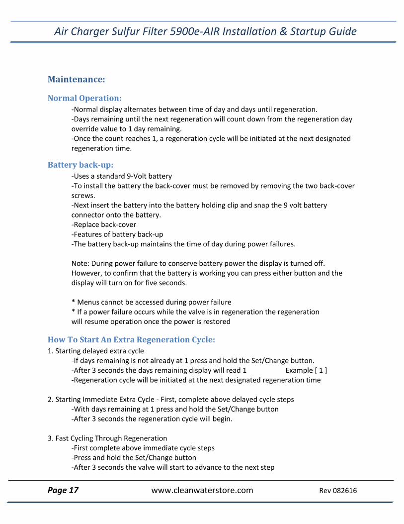
Maintenance:
Normal Operation:
-Normal display alternates between time of day and days until regeneration. -Days remaining until the next regeneration will count down from the regeneration day override value to 1 day remaining. -Once the count reaches 1, a regeneration cycle will be initiated at the next designated regeneration time.
Battery back-up:
-Uses a standard 9-Volt battery -To install the battery the back-cover must be removed by removing the two back-cover screws. -Next insert the battery into the battery holding clip and snap the 9 volt battery connector onto the battery. -Replace back-cover -Features of battery back-up -The battery back-up maintains the time of day during power failures.
Note: During power failure to conserve battery power the display is turned off. However, to confirm that the battery is working you can press either button and the display will turn on for five seconds.
* Menus cannot be accessed during power failure * If a power failure occurs while the valve is in regeneration the regeneration will resume operation once the power is restored
How To Start An Extra Regeneration Cycle:
1. Starting delayed extra cycle -If days remaining is not already at 1 press and hold the Set/Change button. -After 3 seconds the days remaining display will read 1 Example [ 1 ] -Regeneration cycle will be initiated at the next designated regeneration time
2. Starting Immediate Extra Cycle - First, complete above delayed cycle steps
-With days remaining at 1 press and hold the Set/Change button -After 3 seconds the regeneration cycle will begin.
3. Fast Cycling Through Regeneration
-First complete above immediate cycle steps -Press and hold the Set/Change button -After 3 seconds the valve will start to advance to the next step
Air Charger Sulfur Filter 5900e-AIR Installation & Startup Guide
Page 18 www.cleanwaterstore.com Rev 082616
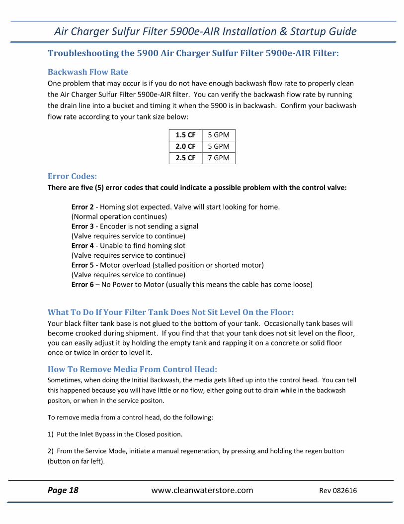
Troubleshooting the 5900 Air Charger Sulfur Filter 5900e-AIR Filter:
Backwash Flow Rate
One problem that may occur is if you do not have enough backwash flow rate to properly clean
the Air Charger Sulfur Filter 5900e-AIR filter. You can verify the backwash flow rate by running
the drain line into a bucket and timing it when the 5900 is in backwash. Confirm your backwash
flow rate according to your tank size below:
1.5 CF 5 GPM
2.0 CF 5 GPM
2.5 CF 7 GPM
Error Codes:
There are five (5) error codes that could indicate a possible problem with the control valve:
Error 2 - Homing slot expected. Valve will start looking for home. (Normal operation continues) Error 3 - Encoder is not sending a signal (Valve requires service to continue) Error 4 - Unable to find homing slot (Valve requires service to continue) Error 5 - Motor overload (stalled position or shorted motor) (Valve requires service to continue) Error 6 – No Power to Motor (usually this means the cable has come loose)
What To Do If Your Filter Tank Does Not Sit Level On the Floor:
Your black filter tank base is not glued to the bottom of your tank. Occasionally tank bases will become crooked during shipment. If you find that that your tank does not sit level on the floor, you can easily adjust it by holding the empty tank and rapping it on a concrete or solid floor once or twice in order to level it.
How To Remove Media From Control Head: Sometimes, when doing the Initial Backwash, the media gets lifted up into the control head. You can tell
this happened because you will have little or no flow, either going out to drain while in the backwash
positon, or when in the service positon.
To remove media from a control head, do the following:
1) Put the Inlet Bypass in the Closed position.
2) From the Service Mode, initiate a manual regeneration, by pressing and holding the regen button
(button on far left).
Air Charger Sulfur Filter 5900e-AIR Installation & Startup Guide
Page 19 www.cleanwaterstore.com Rev 082616
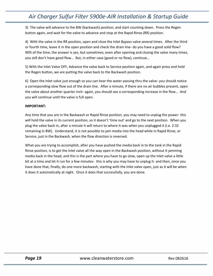
3) The valve will advance to the BW (backwash) position, and start counting down. Press the Regen
button again, and wait for the valve to advance and stop at the Rapid Rinse (RR) position.
4) With the valve in the RR position, open and close the Inlet Bypass valve several times. After the third
or fourth time, leave it in the open position and check the drain line- do you have a good solid flow?
90% of the time, the answer is yes, but sometimes, even after opening and closing the valve many times,
you still don’t have good flow… But, in either case (good or no flow), continue…
5) With the Inlet Valve OFF, Advance the valve back to Service position again, and again press and hold
the Regen button, we are putting the valve back to the Backwash position.
6) Open the Inlet valve just enough so you can hear the water passing thru the valve- you should notice
a corresponding slow flow out of the drain line. After a minute, if there are no air bubbles present, open
the valve about another quarter inch- again, you should see a corresponding increase in the flow… And
you will continue until the valve is full open.
IMPORTANT:
Any time that you are in the Backwash or Rapid Rinse position, you may need to unplug the power- this
will hold the valve in its current position, so it doesn’t ‘time out’ and go to the next position. When you
plug the valve back in, after a minute it will return to where it was when you unplugged it (i.e. 2:32
remaining in BW). Understand, it is not possible to jam media into the head while in Rapid Rinse, or
Service, just in the Backwash, when the flow direction is reversed.
What you are trying to accomplish, after you have pushed the media back in to the tank in the Rapid
Rinse position, is to get the Inlet valve all the way open in the Backwash position, without it jamming
media back in the head, and this is the part where you have to go slow, open up the Inlet valve a little
bit at a time and let it run for a few minutes- this is why you may have to unplug it- and then, once you
have done that, finally, do one more backwash, starting with the Inlet valve open, just as it will be when
it does it automatically at night. Once it does that successfully, you are done.