Air Blaster GW - Global Manufacturing€¦ · air to enter the Air Blaster. The pressure of the...
32
Global Manufacturing Inc. ® 1801 East 22nd St Little Rock, Arkansas 72206 501.374.7416 TEL 800.551.3569 TOLL FREE USA & CANADA 501.376.7147 FAX AIR BLASTERS VIBRATORS VIBRATORS GlobalManufacturing.com Copyright © 2017 by Global Manufacturing, Inc AB_05/09/17 rev 1 Air Blaster Operating Instructions Global ® Pneumatic Air Blaster GW Series GW2.5-8-24 GW4-12-28 GW4-16-34 GW4-20-30 GW6-24-48 GW6-30-60
Transcript of Air Blaster GW - Global Manufacturing€¦ · air to enter the Air Blaster. The pressure of the...

Global Manufacturing Inc.®
1801 East 22nd StLittle Rock, Arkansas 72206501.374.7416 TEL
800.551.3569 TOLL FREE USA & CANADA
501.376.7147 FAX
A I R B L A S T E R SV I B R A T O R SV I B R A T O R S
GlobalManufacturing.com
Copyright © 2017 by Global Manufacturing, IncAB_05/09/17 rev 1
Air BlasterOperating Instructions
Global®
Pneumatic Air Blaster
GW Series
GW2.5-8-24
GW4-12-28
GW4-16-34
GW4-20-30
GW6-24-48
GW6-30-60

2
Global Manufacturing, Inc ® 800.551.3569 TOLL FREE USA & CANADA1801 East 22nd Street 501.374.7416 TEL 501.376.7147 FAXLittle Rock, AR 72206 USA www.G l oba lManu f a c t u r i ng . c om
Table of Contents PageI. Introduction
What is an Air Blaster and Applications 3
Safety Precautions 4
II. Air Blaster Operation
General overview - How the Air Blaster works 5
Air requirements and Air Filtration 5
Lubrication 5
When to "fire" the Air Blaster 5
Methods of control - Manual versus Automatic operation 6
Use of a quick exhaust valve 6
Required accessories 6 - 7
Test firing the Air Blaster 7
III. Installation
Preparation and background 7 - 11
Visual inspection 11
Temporary plug removal 11
Installing discharge pipe 11 - 14
Mounting the Air Blaster to the discharge pipe 12 - 13
General piping instructions for Air Blaster System air control components 14
Air Blaster control components installation 15 -18
IV. Air Blaster Start-Up Procedures 19
V. Maintenance 19
VI. Disassembly And Assembly Of The Air Blaster
Dismounting the Air Blaster 20
Removing the internal valve 20 - 21
Valve disassembly and inspection 21
Assembling the valve 22
Assembling the Air Blaster 22
Testing the Air Blaster 23
Appendix A Troubleshooting 24
Appendix B System Spare Parts Recommendations 25
Appendix C Air Blaster dimensions 26
Appendix D Air Blaster plumbing diagrams 27
Appendix E Air Blaster performance data 28
Appendix F Air Blaster parts drawings 29 - 31
Appendix G Coordinates & Dimensions of elliptical openings for tangential mounts 32

3
Global Manufacturing, Inc ® 800.551.3569 TOLL FREE USA & CANADA1801 East 22nd Street 501.374.7416 TEL 501.376.7147 FAXLittle Rock, AR 72206 USA www.G l oba lManu f a c t u r i ng . c om
I. IntroductionThis manual will assist in the installation and operation of Global GW Series direct blast Air Blasters. Please read the entire manual to assure proper installation, operation, and maintenance of this equipment. These instructions apply to the following models:
GW2.5-8-24: 2.5" discharge 8" x 24" tank 20L GW4.0-12-28: 4" discharge 12" x 28" tank 50L GW4.0-16-34: 4" discharge 16" x 34" tank 100L GW4.0-20-30: 4" discharge 20" x 30" tank 150LGW6.0-24-48: 6" discharge 24" x 48" tank 300L GW6.0-30-60: 6" discharge 30" x 60" tank 650L
What is an Air Blaster?Global Air Blasters are direct blast aerators consisting of a compressed air reservoir with a quick opening valve that releases the stored air in a sudden, high energy blast. This blast is directed through a discharge pipe to restore material flow by aerating and dislodging material that is bridging, arching, rat holing, or clinging.
The direct blast design allows the stored air in the reservoir to escape directly into the discharge pipe without bends or obstructions that could impede the flow of air. This is important because the quicker the air discharges, the greater the velocity and force of the blast and, therefore, the greater the amount of material affected. Air Blasters are activated manually or by a micro-controller based sequencing timer which controls the firing time interval and sequence of one or more Air Blasters. Global Manufacturing offers two lines of direct blast aerators, the GW and GWE Series for general use (ambient temperatures below 130°F/55°C) and the G400 Series for high temperature applications (ambient temperatures up to 400°F/200°C) such as cement kilns and steel mills where internal kiln temperatures can be as high as 2,000°F or 1,100°C (mounting instructions must be strictly followed for high temp applications). We also have a subzero model available.
Applications:Air Blasters easily solve bulk flow problems in silos, hoppers, chutes, and storage piles. They are used where vibration is not practical, or when other methods are too expensive, dangerous, or destructive. Air Blasters are recommended for a wide range of material clogs and jams, and are well suited for large structures of any type. They are commonly used when it is impractical to vibrate stuck material loose, and are effective for very cohesive, difficult materials. For instance, large concrete bunkers and storage piles on the ground are impossible to vibrate, but are common locations of flow problems. Wood chips are very difficult to dislodge by other means, but respond very well to the quick-release Air Blaster. Air Blasters are also used to periodically aerate material sitting in bins, hoppers, and silos.
Bridging Arching Ratholing Clinging

4
Global Manufacturing, Inc ® 800.551.3569 TOLL FREE USA & CANADA1801 East 22nd Street 501.374.7416 TEL 501.376.7147 FAXLittle Rock, AR 72206 USA www.G l oba lManu f a c t u r i ng . c om
DANGER!
The air blast can exceed 1,000 ft/sec (300 m/sec) and 1,500 lb (680 kg) of force. Be sure to read and follow all safety precautions.
◊ Do not stand in front of any Air Blaster during discharge. The air blast can cause serious injury.
◊ Use of an Air Blaster to shoot a projectile may cause serious injury or death.
◊ Global Air Blaster pressure vessels are ASME code welded and certified. Do not weld onto the pressure vessel (tank). Welding to the tank will void ASME certification and may cause vessel malfunction.◊ All OSHA, ANSI and owner’s safety procedures and regulations must be followed during installation, operation, and maintenance of Air Blasters.◊ Do not discharge Air Blaster into open air without clear warnings to all persons in the area.
◊ All Air Blasters must be empty of air when being transported, mounted, or inspected.◊ Due to recoil, do not discharge an Air Blaster that is not securely mounted to a structure.◊ Mount Air Blaster securely on Schedule 40 pipe or equivalent. If the structure is not sufficiently rigid to support the Air Blaster, obtain special mount hardware from your distributor.◊ Attach the ring on the end of the Air Blaster tank to a structural support with a safety cable to prevent the Air Blaster from falling if its supports were to give way.◊ Do not enter application structure (i.e. bin or hopper) if Air Blasters are pressurized and ready to be discharged.
◊ Do not allow the internal pressure in a closed storage vessel to exceed its limitations when the Air Blasters are fired. This may cause damage to the storage vessel. Install exhaust vents if pressures exceed 0.5 psi (0.034 bar). The momentary vessel pressure following the firing of an Air Blaster can be estimated as follows:
Pm = Air Blaster tank pressure (psi or atm) x Air Blaster tank volume (ft3 or liters) Air Blaster tank volume (ft3 or liters) + Structure volume (ft3 or liters)
SAFETY PRECAUTIONS
WARNING!
Caution!

5
Global Manufacturing, Inc ® 800.551.3569 TOLL FREE USA & CANADA1801 East 22nd Street 501.374.7416 TEL 501.376.7147 FAXLittle Rock, AR 72206 USA www.G l oba lManu f a c t u r i ng . c om
II. Air Blaster Operation
General Overview—How the Air Blaster Works:Each Blaster is charged with compressed air through an air inlet controlled by a 3-way normally open valve (either a manual valve or a solenoid valve). Once filled, the Air Blaster remains charged as long as pressure to the tank is maintained by pressure in the fill line. To fire the Air Blaster, pressure in the fill line is suddenly reduced by switching the 3-way valve, evacuating the air in the fill line to the atmosphere. After firing, re-switching the 3-way valve will restore plant air allowing the Air Blaster to refill. A step-by-step outline of the filling and discharging process follows:
1. A 3-way valve in the open position allows plant air to enter the Air Blaster. The pressure of the plant air insures an air tight seal between the piston and seat, preventing any air loss while Air Blaster is waiting to be fired.
2. Plant air is forced out through the check valve in the valve cap to fill the pressure vessel with air.
3. Once filled, the Air Blaster remains on standby waiting to be fired.
4. When the 3-way valve is switched, air in the fill line is exhausted, causing the air pressure at the back of the piston to drop.
Air Requirements:
For optimum performance, operate the Air Blaster on filtered, regulated air between 45 and 125 psi (3 - 8.6 bar). The pressure may be adjusted to obtain the desired amount of blast force (generally 80-100 psi). Refer to the performance data in Appendix E to see how the blast force varies with air pressure and to determine the quantity of air needed to fill the Air Blaster for each pressure level. Use a standard air compressor, however, nitrogen, carbon dioxide or another inert gas can be used in place of the normal air supply. The Air Blaster pressure vessel has a 125 psi pressure relief valve (safety valve) and will completely exhaust the compressed air inside the tank without firing the Air Blaster if the ring is pulled (see page 20).
5. Due to the pressure differential created, the tank pressure forces the piston back into the open position.
6. The compressed air in the pressure vessel escapes through the discharge in an explosive blast that lifts and separates material particles, restoring material flow.
7. The 3-way valve is re-switched allowing the plant air to recharge the Air Blaster.
8. The pressure of the plant air forces the piston to close against the valve seat preventing contaminants from entering the Air Blaster.
Air Filtration:Use filtered (40 Micron) compressed air to fill and operate the Air Blaster.
Lubrication:Global Air Blasters require no lubrication.
When to "Fire" the Air Blaster:It is best to discharge the Air Blaster only when a material flow problem occurs. Firing too often when the storage vessel discharge is closed is not recommended. A group of Air Blasters may be fired sequentially using the Global Blaster Master micro-controller based sequencing timer.
1
1
2 2
Air Blaster filled and in standby Air Blaster discharging Air Blaster recharging4
6 6
6
6
5
8
7
8 8

6
Global Manufacturing, Inc ® 800.551.3569 TOLL FREE USA & CANADA1801 East 22nd Street 501.374.7416 TEL 501.376.7147 FAXLittle Rock, AR 72206 USA www.G l oba lManu f a c t u r i ng . c om
Methods of Control - Manual versus Automatic Operation:
Control a Global Air Blaster System either manually or automatically:
Manual Operation: For strictly manual operation the Air Blaster is controlled by a 3-way normally open manual valve. This type of valve has 3 ports - an inlet to connect to the air source, an outlet to connect to the Air Blaster, and an exhaust port. A ¾" valve is used for the GW2.5-8-24, GW4.0-12-28, GW4.0-16-34, and GW4.0-20-30 models, and a 1" valve is used for the GW6.0-24-48 and GW6.0-30-60 models. The manual 3-way valve is placed in the "open" position to fill the Air Blaster and to keep it pressurized in a standby, ready-to-fire mode. To discharge the Air Blaster, the valve is moved to the "closed" position, which exhausts the air in the fill line between the valve and the Air Blaster. This sudden decrease in line pressure fires the Air Blaster. The valve should be returned to the "open" position to refill the Air Blaster for its next use. If manual operation is desired, but the manual valve will be placed more than 10 feet (3 m) from the Air Blaster or will be smaller than the size recommended above, use a quick exhaust valve with the manual valve to ensure optimum performance of the Air Blaster (see "Use of a Quick Exhaust Valve" below).
Automatic Operation: For automatic operation the Air Blaster is controlled by a 3-way normally open solenoid valve. It has 3 ports - an inlet to connect to the air source, an outlet to connect to the Air Blaster, and an exhaust port. A ¾" Solenoid is used for the GW2.5-8-24, GW4.0-12-28, GW4.0-16-34, and GW4.0-20-30 models, and a 1" solenoid is used for the GW6.0-24-48 and GW6.0-30-60 models. The solenoid is controlled electronically using a Global Blaster Master timer or a manually triggered momentary electric switch. When not energized, the solenoid valve is "open", allowing the Air Blaster to fill with air. The Air Blaster will remain pressurized in a standby, ready-to-fire mode as long as the solenoid valve is open. To discharge the Air Blaster, the solenoid is energized by the timer or switch closure. This closes the solenoid valve, which exhausts the air in the fill line between the solenoid and the Air Blaster. This sudden decrease in line pressure fires the Air Blaster. The timer or opening of the switch de-energizes the solenoid, the valve re-opens and the Air Blaster is re-filled for its next use. If automatic operation is desired, but the solenoid valve will be placed more than 10 feet from the Air Blaster or will be smaller than the
size recommended above, use a quick exhaust valve with the solenoid valve to ensure optimum performance of the Air Blaster (see "Use of a Quick Exhaust Valve" below).
Use of a Quick Exhaust Valve:
The Air Blaster is discharged by reducing the pressure in the internal valve assembly. The quicker the pressure drop occurs, the faster the Air Blaster piston opens, therefore the faster and more forceful the air blast. To obtain optimum Air Blaster performance (maximize the force for the air pressure being used), the device used for exhausting the fill line needs to be as close to the Air Blaster as possible. Mount the 3-way normally open valve (manual or solenoid) used to discharge the Air Blaster directly to the air inlet port on the Air Blaster pressure vessel. The further the valve is located from the Air Blaster, the more the blast will be degraded. If the valve (manual or solenoid) is located more than 10 feet (3 m) from the Air Blaster, mount a quick exhaust valve to the air inlet port of the Air Blaster pressure vessel. The quick exhaust valve is actuated by the 3-way valve and will quickly reduce the air pressure in the internal valve, resulting in maximum Air Blaster performance. Use a ¾" quick exhaust valve for the GW2.5-8-24 model and a 1" or larger quick exhaust valve for all other models.
Using the recommended quick exhaust valve mounted on the
Air Blaster air inlet port will ensure optimum performance of your Global Air Blaster.
Required Accessories:
This manual includes instructions for installing a complete Air Blaster system. The following air control components are necessary for Global GW Series Air Blasters to be fully operational. They are available from Global Manufacturing and your Global distributor:
1. Shut-off Ball Valve: A 2-way shut-off ball valve is used to isolate the Air Blaster system from the plant air supply. Install it between the plant air supply and all other components in the Air Blaster system. Clearly label and locate the shut-off valve where it can be quickly and easily reached in an emergency or for routine maintenance. Use one shut-off valve for each filter-regulator-gauge used in the system. A ¾" or larger valve is recommended for all Air Blaster models.
NOTE

7
Global Manufacturing, Inc ® 800.551.3569 TOLL FREE USA & CANADA1801 East 22nd Street 501.374.7416 TEL 501.376.7147 FAXLittle Rock, AR 72206 USA www.G l oba lManu f a c t u r i ng . c om
2. Filter-Regulator-Gauge: The f i l ter-regulator-gauge (FRG) protects the Air Blaster and airline components by filtering water and particulate contaminants from the air supply. It also is used to control the force output of the Air Blaster by regulating the air pressure (determines the volume of air stored in the Air Blaster pressure vessel). For optimum performance drain the filter reservoir of the FRG daily. For this reason, an FRG that drains automatically may be desired. We recommend using one (1) FRG for every four (4) Air Blasters. A ¾" FRG is recommended for all Air Blaster models.
3. Airline Check Valve: The airline check valve prevents accidental firing of the Air Blaster due to pressure loss in the main supply line. If the main airline loses pressure, the check valve maintains pressure to the Air Blaster by preventing backward air flow. Use one check valve for every Air Blaster, and install it between the FRG and the 3-way control valve. A ¾" check valve is recommended for all Air Blaster models.
4. 3-Way Control Valve: The 3-way control valve controls the firing of the Air Blaster. When in the open position, the Air Blaster is filled with air and maintained in the standby, ready-to-fire mode. When closed, the Air Blaster is discharged. A ¾" control valve can be used and located up to 100 feet (30 m) from the Air Blaster for all models when the recommended quick exhaust valve is also used (see below). For manual firing only, use a manual valve. For automatic firing, use a solenoid valve. When no quick exhaust valve is used, it is recommended the 3-way normally open valve be placed within 10 feet (3 m) of the Air Blaster. Increase the size of the valve to 1" for the GW6.0-24-48 and GW6.0-30-60 models.
5. Quick Exhaust Valve: For optimum Air Blaster performance, place a quick exhaust valve (QEV) in the supply airline, at the Air Blaster pressure vessel air inlet port. This valve ensures the rapid depressurization of the Air Blaster valve necessary to fire the Air Blaster and produce maximum blast force. When using a QEV, the 3-way normally open valve (manual or solenoid) can be placed up to 100 feet (30 m) from the Air Blaster without any substantial loss of blast performance. A ¾" QEV is recommended for the GW2.5-8-24 model and a 1" or larger QEV is recommended for all other models.
Test Firing the Air Blaster:Before mounting the Air Blaster to the discharge pipe for the first time (or before remounting after servicing the Air Blaster valve), do a test firing. During tests, place the Air Blaster on its side with
the end opposite the discharge opening adequately supported to withstand the recoil that occurs when the Air Blaster is fired. The pressure relief valve must be in place. Minimum pressure for testing is 40 psi (3.1 bar)
Because of the hazards associated with the force of the blast and the recoil, do not fill the Air Blaster pressure vessel beyond 60 psi (4.1 bar) for testing purposes. Minimum pressure for testing is 40 psi (3.1 bar).
Warn Personnel in the testing area to stay way from the Air Blaster discharge outlet. The air blast can cause serious injury.
Wear eye and ear protection. Air Blasters produce a very loud noise when discharged in open space.
III. Installation
Preparation and Background:
Air Blaster Placement: To be sure Air Blasters provide the greatest effect, it is important to properly locate them on the storage structure. The placement and quantity of Air Blasters depends on several factors.
1. Shape of the storage structure: In general, square structures require more Air Blasters than round structures because materials tend to hang up in the corners. Be sure the Air Blasters will reach all major problem areas such as corners and the base of any known or suspected areas of bridging, arching, rat holing, or clinging.
2. The degree of material flow desired: If Air Blasters are used to constantly move or aerate the material, or if the sides of the storage structure must be kept very clean, more Air Blasters will be needed than if they are only used to restore material flow after a stoppage.
3. Properties of the bulk material: Each Air Blaster has an approximate "area of influence" which varies with the properties of the bulk material. As a rule of thumb, for Air Blaster applications, bulk materials are grouped into the two categories described as Type I or Type II (page 8).
4. Additional Guidelines: If the discharge pipe will be longer than 6 feet (1.8 meters) in length, it is recommended that the next larger size Air Blaster be used.
WARNING!

8
Global Manufacturing, Inc ® 800.551.3569 TOLL FREE USA & CANADA1801 East 22nd Street 501.374.7416 TEL 501.376.7147 FAXLittle Rock, AR 72206 USA www.G l oba lManu f a c t u r i ng . c om
GW2.5-8-246 feetType II
4 feetType I
8 feetType II
5 feetType I
9 feetType II
6 feetType I
10 feetType II
7 feetType I
12 feetType II
8 feetType I
10 feetType I
15 feetType II
GW4-12-28
GW4-16-34
GW4-20-30
GW6-24-48
GW6-30-60
Area-of-Influence
The Area of Influence data is based on filling the Air Blaster at 90 p.s.i. (6.2 bar). NOTE
NOTE If your bulk material has two or more of the properties listed for
Type I, consider it a Type I Material. If it has none or only one of the properties for Type I, but has several Type II properties, consider it a Type II Material.
Use the following charts and diagrams to assist in determining the number and placement of the Air Blasters. For best coverage, make sure the areas of influence of the Air Blasters overlap.
Type II Material
Stored in structure with high sloping wallsStored in structure with large discharge outletDensity less than 55 lb/ft3 (880 kg/m3)Does not clingSpongy and does not compactDry or powderyFlows easily under most conditions
Type I Material
Stored in structure with low sloping walls Stored in structure with small discharge outletDensity in excess of 55 lb/ft3 (880 kg/m3) Clings, regardless of weight Compacts easily Greasy or pasty consistency "Sets up" or hardens during holding Large chunks or mixed size Heavily oil– or water-laden

9
Global Manufacturing, Inc ® 800.551.3569 TOLL FREE USA & CANADA1801 East 22nd Street 501.374.7416 TEL 501.376.7147 FAXLittle Rock, AR 72206 USA www.G l oba lManu f a c t u r i ng . c om
Air Blaster Model
Material Type
Number of Air Blasters Recommended per Bin/Hopper Area of InfluenceDiameter of Structure
ft 3 5 10 15 20 25 30 35 40 45 50 ft m
m 1 1.5 3 4.5 6 8 9 10.6 12 14 15
2.5" Discharge
GW2.5-8-24I 1 3 6 9 12 15 18 21 24 27 30 4 1.2
II 1 2 3 5 6 7 8 10 12 13 15 7 2.1
4" Discharge
GW4-12-28I * 3 4 6 10 12 14 16 18 20 25 6 1.8
II * 2 3 4 5 6 7 8 10 11 12 9 2.7
GW4-16-34I * 2 3 6 9 11 13 14 17 18 22 7 2.1
II * 1 2 3 4 5 6 7 8 9 11 10 3.0
GW4-20-30I * 2 4 6 8 10 11 12 15 16 18 7 2.1
II * 1 2 3 4 5 6 7 8 9 10 10 3.0
6" Discharge
GW6-24-48I * 2 3 5 6 8 9 10 12 14 16 8 2.4
II * 1 2 3 4 5 6 7 8 9 10 12 3.7
GW6-30-60I * 1 2 3 4 5 7 10 10 11 12 10 3.0
II * 1 1 2 2 2 2 3 4 5 5 16 4.9
*This application is too small for this model Air Blaster.
Aiming the Air Blast: For Air Blasters to provide the greatest effect, it is important to aim them properly. Direct the blast at problem areas such as corners and the base of any known or suspected areas of bridging, arching, rat holing, or clinging. However, directing the blast straight out into the storage structure most often has disappointing results. A much more productive blast is one that skims the internal surface of the structure, forcing the problem material from the wall and allowing gravity to pull it down towards the storage vessel outlet. Therefore, where possible, direct the blast so it will parallel the inside wall, shearing material away from the wall to restore material flow. Since this is often difficult, Global Manufacturing developed and patented a Tangential Mount system. With Tangential Mounting the Air Blaster discharge is directed downward at a steep angle and to the side. This achieves the following:
1. The "tangential" angling of the discharge (at least 60° below the perpendicular to the storage structure wall) helps the blast to skim material from the wall.2. The downward orientation pushes the bulk material toward the storage structure outlet and also prevents loosened material from entering the discharge pipe and possibly contaminating the Air Blaster valve.
3. The sideward angling of the discharge (same direction for all Air Blasters on the structure) helps expand the area of influence around the circumference of the structure and promotes a "cyclone" motion of the material all in one rotary direction, further assisting in the flow of material.
When using tangential mounting, overlap blast patterns to give the most effective coverage. Aim the first Air Blaster towards the outlet of the storage structure. Spiral Blasters around the structure, always keeping in mind the area of influence.
Top View

10
Global Manufacturing, Inc ® 800.551.3569 TOLL FREE USA & CANADA1801 East 22nd Street 501.374.7416 TEL 501.376.7147 FAXLittle Rock, AR 72206 USA www.G l oba lManu f a c t u r i ng . c om
To assist with mounting and aiming of Air Blasters, Global Manufacturing offers Tangential Mount Discharge Assemblies. These mount assemblies which can be welded or bolted to the storage structure direct the air blast downward (60° below the perpendicular to the wall) and 20° to the right. The discharge assembly supports the Air Blaster as well (see pg 11 for adequate structure wall thickness) and includes a mount flange for the Air Blaster and all hardware. Shown is a Tangential Mount Discharge Assembly with a 4" discharge. Also available for a 2.5" or 6" discharge. (Either a ring gasket or full-face gasket is supplied with discharge assembly.)
Examples of Air Blaster System Configurations using Tangential Mounting
Air Blaster Orientation: In general, it is best to mount the Air Blaster so the discharge pipe is straight and as short as possible. This allows the maximum blast force to be applied to the material in the storage vessel. A downward slant to the discharge pipe helps prevent the stored material from contaminating the Air Blaster. However, due to space limitations, these guidelines cannot always be followed. Sometimes the discharge pipe will have to have a bend or be longer in length, and the Air Blaster may need to be oriented at different angles. If the air source is of poor quality, containing much water, or if condensation is a problem, the Air Blaster pressure vessel will need to be drained occasionally. To assist in draining the tank, three accessory ports are provided; one on the side of the tank, one on the end near the discharge, and one on the end near the air inlet. When mounting, be sure the Air Blaster is oriented so two of these ports are pointed downward. Once the Air Blaster is mounted, place a drain valve in the lowest of the three ports. One of the other accessory ports is used for the safety relief valve (provided with the Air Blaster). Air Blasters manufactured before May 2001 have only two accessory ports. They do not have the port on the end of the tank opposite the discharge pipe (next to the current air inlet port).
4.0"Diameter
Pipe
9.0" Diameter
Nuts
8"
30°
16"
Gasket
Lock Washers
Flange Connectionfor Air Blaster
Bolts
3/8"
12.00"
12.00"
PressureRelief Valve
DrainValve

11
Global Manufacturing, Inc ® 800.551.3569 TOLL FREE USA & CANADA1801 East 22nd Street 501.374.7416 TEL 501.376.7147 FAXLittle Rock, AR 72206 USA www.G l oba lManu f a c t u r i ng . c om
Required Storage Structure Wall Thickness: The storage structure wall must be rigid enough to support the weight of the Air Blaster and withstand the forces that occur during discharge. Reinforce structure walls less than " (5 mm) thick. Please see minimum thickness requirements below. Tank Mount Hardware is available from Global Manufacturing to help support the weight of the Air Blaster and withstand the firing forces.
Air Blaster Plumbing: As described under "Required Accessories" (page 6) there are a number of air control components necessary for full operation. To ensure safe operation and optimum performance of your Air Blaster system, install these air control components as shown in the plumbing diagrams in Appendix D, page 27. The "Using a Quick Exhaust Valve Air Blaster Plumbing Diagram" gives the highest level of performance while allowing the control valve (manual or solenoid) to be located up to 100 feet (30 m) from the Air Blaster. "Not Using a Quick Exhaust Valve Air Blaster Plumbing Diagram" will also give high performance if the control valve (manual or solenoid) is located within 10 feet (3 m) of the Air Blaster.
Visual Inspection: Please note the condition of the shipping container before opening. The shipping container will include the Air Blaster, pressure relief valve and operating instructions. Make sure all parts are located before discarding the container. Inspect the Air Blaster for any damage, such as dents, that might have occurred during shipment. Any Air Blaster accessories (valves, discharge assemblies, timers, etc.) ordered from Global Manufacturing will be packaged separately. Please verify that all items ordered have been received. Contact Global Manufacturing Customer Service or your distributor if there are any missing parts, apparent damage, or other irregularities. Report any damage to the delivery service. Complete any necessary claim forms.
Air Blaster Model
Weight Minimum Wall Thickness
lb kg inches
GW2.5-8-24 56 25 3⁄16
GW4-12-28 94 43 3⁄16
GW4-16-34 116 53 3⁄16
GW4-20-30 128 58 ¼GW6-24-48 260 118 ¼GW6-30-60 554 251 ¼
Temporary Plug Removal: Tank openings are fitted with plastic plugs which are removed prior to attaching the air line, discharge pipe, or pressure relief valve. The small port at the end of the tank near the discharge opening has a steel plug. This is a permanent plug that should not be removed unless this port is needed for a drain valve or as an alternate location for the pressure relief valve.
Installing Discharge Pipe: The discharge assembly must be able to support the Air Blaster and directs the air blast towards the problem area.
Structure Wall Opening: Instructions for making the opening for the discharge pipe in the storage structure wall are not specific because of the wide variety of structures, wall materials, etc. Generally, the hole in the wall for the discharge pipe will be circular if the pipe is entering perpendicular to the wall or elliptical if using Global Manufacturing’s patented Tangential Mounting. The chart in Appendix G, page 32, defines the height and width of the ellipse for each of the three discharge pipe sizes offered. These are for a 60° downward slope (from perpendicular to the wall surface) and a 20° rotation to the right.
Before working on any storage structure, lock out - tag out any equipment that loads or unloads material from the structure.
If equipment will be installed in an enclosed area, test gas levels or dust content before using a cutting torch or welding equipment. Using a cutting torch or welding in an area with sufficient gas or dust levels can cause an explosion.
WARNING!
Air BlasterMount Hardware
3⁄16
Air Blaster Mount Hardware cannot be used with our standard tangential mount discharge assemblies

12
Global Manufacturing, Inc ® 800.551.3569 TOLL FREE USA & CANADA1801 East 22nd Street 501.374.7416 TEL 501.376.7147 FAXLittle Rock, AR 72206 USA www.G l oba lManu f a c t u r i ng . c om
Before cutting a hole in the structure wall, be sure there is adequate space to mount the Air Blaster to the discharge assembly.
Discharge Pipe Features: If not using a discharge assembly provided by Global Manufacturing, please use the following guidelines in constructing a discharge pipe:
1. Use schedule 40 steel pipe for most applications.2. Avoid sharp bends in the discharge pipe. Where bends are necessary, use a long radius elbow for a more effective blast.3. Keep the length of the pipe as short as possible. The longer the discharge pipe, the more the blast force is diminished. If the pipe must be more than 6 feet (1.8 m) long consider using the next larger size Air Blaster.4. When determining the pipe length keep in mind the length of pipe needed to give proper clearance for the Air Blaster tank to clear the structure wall, the thickness of the wall, and the amount of pipe that will be extending into the storage area.
5. The pipe should extend into storage area far enough to be cut at a 45° angle to form a "pocket" around the pipe end to prevent material from clogging it.
6. Use a standard slip-on pipe flange to mount the Air Blaster to the discharge pipe. Select the size (2.5", 4.0", or 6.0") to match the pipe size and the mounting flange on the Air Blaster.
Installing the Global Tangential Mount Discharge Assembly:
1. Determine the location of the Air Blaster discharge pipe. Be aware of structural obstacles which may interfere with mounting the Air Blaster to the mount flange on the end of the discharge pipe.2. Using the Coordinates and Dimensions of Elliptical Openings in Appendix G, make a template of cardboard or other durable material. Enlarge the elliptical shape of the pattern by ½" (13mm) for ease of fitting during installation. The pattern may also be used to locate bolt holes if the mount plate is to be bolted to the structure wall.
Important!
3. Use the pattern to mark the opening on the structure wall. When working from the outside of the structure, the long diameter of the elliptical shape should run from upper left to lower right (unless you have ordered a special configuration).4. Cut the hole in the structure wall.5. Fit the discharge pipe into the wall so the mount plate is flush with the outer wall surface. Evaluate the amount of pipe extending into the storage chamber. Cut the pipe using a square cut (perpendicular to the length of the pipe) so the lower edge is flush with the inside of the structure wall. The upper edge will protrude into the flow area slightly.6. Be sure the discharge assembly is in place with the mount plate flush with the outer wall surface. Seal weld the mount plate to the wall.
1/4"
Connection to
Air Blaster
HopperWall
CutEllipse
CutExcess
MountPlate
DischargePipe
TOP
AIR BLASTER SIDE
TankFlange
Air Blaster Coupling
Discharge Pipe
Mount Plate
Pattern
Ellipse
Discharge Pipe End
Air Blaster Tank
Air BlasterMount Flange

13
Global Manufacturing, Inc ® 800.551.3569 TOLL FREE USA & CANADA1801 East 22nd Street 501.374.7416 TEL 501.376.7147 FAXLittle Rock, AR 72206 USA www.G l oba lManu f a c t u r i ng . c om
If the storage structure wall is too curved and leaves an
excessive gap for welding, trim the mount plate with a torch to the required size to reduce the gap as shown below. Do not trim the mount plate closer than 2" (50 mm) from the discharge pipe. The remaining flange must overlap the mounting surface by at least ½" (12 mm). After trimming the mount plate, reposition the discharge assembly in the structure wall and seal weld the mount plate to the outer wall surface.
If the discharge assembly will be bolted to the structure wall, use
at least four (4) ⅝" (16mm) bolts to secure the mount plate. Drill holes in mount plate at least 1½" in from each corner. Anchor bolts must extend at least 3" into the concrete wall. Otherwise the bolts should extend through the wall and be secured with lock washers and nuts. Use gasket material between the mount plate and structure wall or apply sealant to the mount plate-wall joint to prevent air or material leakage.
Mounting Air Blaster to the Discharge Pipe The Air Blaster coupling flange is connected to a discharge pipe equipped with a mount flange. Be sure to rotate the Air Blaster to place the small ports facing downward (in case they will be needed to drain the Air Blaster tank at a future time).
The discharge pipe must be securely mounted to the storage structure wall. If any doubt about the rigidity of the mount exists, Global Manufacturing strongly recommends using additional mount hardware to secure the Air Blaster. Contact Global Manufacturing or your distributor.
1. Secure the Air Blaster coupling flange to the mounting flange on the discharge assembly using a gasket (either full-face or ring gasket) and the Grade 5 bolts, nuts, and washers provided. Use bolts no smaller than ⅛" (3 mm) less than the coupling bolt hole diameter. The bolts are tightened in three stages in a crisscross pattern to ensure even tightening.
2. Be sure to install a safety cable to keep the Air Blaster from falling should it break loose from its mount. Use the ring on the end of the tank for this purpose. Securely attach the other end of the safety cable to a structural member.
NOTE
NOTE
WARNING!
Before Flame-cut
Flange
Mount Plate
Discharge Pipe
Air Blaster Coupling
Gasket Seal
Mounting Surface
Mounting Flange
Air Blaster
Discharge Pipe
Tank Flange
After Flame-cut
Flame-cut
2"min.
Connection to
Air Blaster
HopperWall
CutEllipse
Mount Plate
DischargePipe
⅝" (16 mm) Boltsminimum
Gasket
CutExcess
Need overhang (gray area) to prevent material from entering discharge

14
Global Manufacturing, Inc ® 800.551.3569 TOLL FREE USA & CANADA1801 East 22nd Street 501.374.7416 TEL 501.376.7147 FAXLittle Rock, AR 72206 USA www.G l oba lManu f a c t u r i ng . c om
If the Air Blaster is mounted more than 6" (152 mm) above the ground, secure the Air Blaster to a structural member with a safety cable to prevent the Air Blaster from falling and causing serious injury if it came loose from its mount.
If a safety cable kit has been purchased from Global Manufacturing, attach one end of the cable to the steel ring with the provided clamp. The steel ring can be welded to or looped around a structural support. Using the other clamp, attach the other end of the cable to the safety tab on the end of the Air Blaster tank. Adjust the length of the cable to provide some slack. It should be short enough, however, to stop the Air Blaster from falling and hitting a person.
3. If a drain valve (not supplied) is to be used, install it in the lowest of the three small accessory ports (The tank should be mounted so two of these ports point down). Install the pressure relief valve (safety valve) in the side accessory port, or if that one has been used for a drain valve, in the unused port on either end of the tank (will have to remove the steel plug).
WARNING!Be sure to apply Teflon® tape to all threaded connections.
General Piping Instructions for Air Blaster System Air Control Components: To ensure safe operation and optimum performance of your Air Blaster system, install necessary air control components as shown in the plumbing diagrams in Appendix D, page 27.
1. The "Using a Quick Exhaust Valve Plumbing Diagram" makes use of a quick exhaust valve and gives the highest level of performance while allowing the control valve (manual or solenoid) to be located up to 100 feet (30 m) from the Air Blaster. "Not Using a Quick Exhaust Valve Plumbing Diagram" will also give high performance if the control valve (manual or solenoid) is located within 10 feet (3 m) of the Air Blaster. The distance between the other components is not important except when the Quick Exhaust Valve is connected directly to the Air Blaster inlet port on the pressure vessel. Only the sequence of the components along the air supply line is important. 2. Do not connect more than four Air Blasters to a single Filter-Regulator-Gauge / Shut-off Valve pair.3. The air supply lines required for plumbing Air Blasters and control components must be rated for a minimum of 150 psi (10.3 bar). Use ¾" air lines or greater. If a timer is used to control Air Blaster firing sequence and time delay between blasts, wire each solenoid valve to the appropriate timer terminals. Wiring must adhere to all appropriate electrical standards.
Steel WeldRing
SwagedEnd
SafetyCable
CableClamp
AirBlasterTank
Important!
PressureRelief Valve
DrainValve

15
Global Manufacturing, Inc ® 800.551.3569 TOLL FREE USA & CANADA1801 East 22nd Street 501.374.7416 TEL 501.376.7147 FAXLittle Rock, AR 72206 USA www.G l oba lManu f a c t u r i ng . c om
Air Blaster Control Component Installation:Install each control component using Teflon® tape on all threaded connections.
Be sure all connections are air tight. Any leak along the Air Blaster air supply line may cause the Air Blaster to discharge unexpectedly causing injury.
Shut-off Ball Valve Installation: The 2-way shut-off ball valve is used to isolate the Air Blaster system from the plant air supply. A ¾" valve is recommended. Locate it between the plant air supply and all other components in the Air Blaster system. Each shut-off valve should control no more than four Air Blasters. Be sure to clearly label the shut-off valve and place it where it can be quickly and easily reached in an emergency or for routine maintenance.
2. Filter-Regulator-Gauge: Install the filter-regulator-gauge (FRG) in the air supply line between the shut-off ball valve and the check valve. The FRG is designed to prevent damage to the Air Blaster and control components by filtering water and particulate contaminants from the air supply. A ¾" FRG is recommended. Place the FRG where the filter reservoir can be drained daily (unless an auto-drain model is used). The FRG has an arrow cast in the housing, which indicates the required direction of air flow. It will not function if it is installed in the reverse direction. After installation set the air pressure to the Air Blaster between 80 and 100 psi (5.5 and 6.9 bar) for most applications (If using a solenoid valve in the system, the pressure should not be below 40 psi).
WARNING!
Safety Cable
Plant Air
Solenoid
Filter-Regulator
Shut-off ValveCheck Valve
PressureReliefValve
Timer
Safety Cable
Plant AirSolenoid
Filter-Regulator
Shut-off ValveCheck Valve
Quick Exhaust Valve
Pressure Relief Valve
Timer
Using a Quick Exhaust Valve
Not Using a Quick Exhaust Valve
Clo
sed Open

16
Global Manufacturing, Inc ® 800.551.3569 TOLL FREE USA & CANADA1801 East 22nd Street 501.374.7416 TEL 501.376.7147 FAXLittle Rock, AR 72206 USA www.G l oba lManu f a c t u r i ng . c om
3. Check Valve Installation: The check valve prevents accidental firing of the Air Blaster if an unexpected decrease in line air pressure occurs. The check valve maintains pressure to the Air Blaster by preventing the backward flow of air. Install the check valve in the air supply line between the FRG and the 3-way control valve (manual or solenoid). A ¾" valve is recommended. Be sure to install the valve with the cast-in arrow pointing in the direction of the air flow. If used in a horizontal line, be sure the hex head plug is on top, so the check valve will close properly. In a vertical line, the air flow must be upward in the line.
Do not install in a vertical line where the air flow is downward, because the check valve will not close properly. Do not install with the hex head plug on the bottom or pointing downward, because the check valve will not close properly.
4. 3-Way Normally Open Valve Installation: This valve controls the operation of the Air Blaster. Use either a manual valve for manual control or a solenoid valve for remote or automatic control. The solenoid valve is wired to either a remote manually triggered momentary switch or a micro-controller based sequencing timer such as Global’s BLASTER MASTER timer. Be sure the controller output is compatible with the electrical requirements of the solenoid valve. Follow all applicable local wiring codes.
The control valve is installed in the air supply line between the check valve and the Air Blaster. Location depends on whether a quick exhaust valve is being used or not.
AIR FLOW
AIR FLO
W
AIR FLOW AIR F
LOW
Check Valve in Proper Orientation
Control Valve Illustrations:
Manual 3-Way Valve
¾" 3-Way Open Solenoid Valve
Check Valve in Improper Orientation
Manual 3-Way Valve
Handle in "Fill" Position
To Air Supply
Move to "Fire" Position
Exhaust Port
To Air Blaster
Port 3Exhaust Port
Port 1to
Air Supply
3/4" 3-Way Normally Open Solenoid Valve
Port 2to
Air Blaster
Warning!

17
Global Manufacturing, Inc ® 800.551.3569 TOLL FREE USA & CANADA1801 East 22nd Street 501.374.7416 TEL 501.376.7147 FAXLittle Rock, AR 72206 USA www.G l oba lManu f a c t u r i ng . c om
Connections Without Quick Exhaust Valve
Air Blaster Model
3-Way Valve Size
Solenoid Inlet Port Label
Inlet Bushing Size
Solenoid Outlet Port Label
Pipe Nipple Size for AB
Tank Mounting
Air Line Size for Remote Mount < 10’
GW2.5-8-24 ¾" 1 N/A 2 ¾" x close ¾"
GW4.0-12-28 ¾" 1 N/A 2 ¾" x close ¾"
GW4.0-16-34 ¾" 1 N/A 2 ¾" x close ¾"
GW4.0-20-30 ¾" 1 N/A 2 ¾" x close ¾"
GW6.0-24-48 1" IN 1" x ¾" 2 CYL 1" x close 1"
GW6.0-30-60 1" IN 1" x ¾" 2 CYL 1" x close 1"
Contamination Protection: Connect a street elbow to the solenoid or 3-way firing valve's exhaust port (or the QEV for GW2.5-8-24 but not necessary for Global's manufactured 1" QEV). Position the elbow to point downward and add a 3" long nipple for exhaust extension. Refer to the table below for the appropriate size fittings to be used. The elbow with extension will keep contaminants from entering the valve through the exhaust port. Using a muffler to protect the exhaust port is not recommended, because it will reduce Air Blaster performance by significantly impeding the exhaust air flow.
Important!
Solenoid Valve Size
Exhaust Port Label
Street ElbowSize
NippleSize
¾" 3¾"
pn 293412¾" x 3"
pn 294612
1" EXH1½"
pn 2934241½" x 3"
pn 294624
Quick Exhaust Valve Not Used: Install the 3-Way Control Valve within 10 feet (3 m) of the Air Blaster. Refer to the table below to determine the size of the valve and the appropriate fittings for each Air Blaster model. If a solenoid is used, be sure it is set in the normally open position ('3-NO' is indicated on the small white tab visible from the top). Using an appropriate bushing connect the ¾" air supply line to the valve air inlet port. The valve outlet is connected to the Air Blaster inlet port using the appropriate close pipe nipple or flexible air line.
Be sure to test the solenoid valve before applying air pressure.The solenoid valve may not operate if the inlet pressure is less than 40 psi (2.75 bar).

18
Global Manufacturing, Inc ® 800.551.3569 TOLL FREE USA & CANADA1801 East 22nd Street 501.374.7416 TEL 501.376.7147 FAXLittle Rock, AR 72206 USA www.G l oba lManu f a c t u r i ng . c om
¾" QuickExhaustValve
Plant Air Inlet"IN"
To Air Blaster"CYL" Exhaust
"EXH"
Quick Exhaust Valve Installation for the GW Series: Install a ¾" 3-way control valve within 100 feet (30 m) of the Air Blaster (all models). If a solenoid is used, be sure it is set in the normally open position ('3-NO' is indicated on the small white tab visible from the top). Connect the ¾" air supply line to the valve air inlet port (Solenoid port labeled '1'). The ¾" line connecting the Solenoid to the Air Blaster quick exhaust valve is connected to the valve outlet (Solenoid port labeled '2').
The quick exhaust valve (QEV) allows rapid depressurization of the Air Blaster internal valve assembly, which causes the Air Blaster to discharge. Using the recommended QEV will ensure optimum performance of your Global Air Blaster even when the 3-way control valve is placed more than 10 feet (3 m) from the Air Blaster. If a smaller QEV is used, it will not have sufficient internal air flow capacity to depressurize the Air Blaster valve quickly enough. The Air Blaster will discharge, but the force of the blast will be greatly reduced. Install the QEV to the Air Blaster inlet port using the appropriate size close pipe nipple (and bushing if necessary). The ¾" air supply line from the 3-way normally open valve is connected at the QEV inlet port.
Installing a Quick Exhaust Valve - Connection DetailsAir Blaster
ModelQEV Size
QEV Inlet Port Label
Inlet Size
QEV OutletPort Label
Pipe Nipple Size for AB Tank Mounting
GW2.5-8-24 ¾" IN ¾" CYL ¾" x close (pn 294602)
GW4.0-12-28 1" IN ¾" AB 1" x close (pn 294614)
GW4.0-16-34 1" IN ¾" AB 1" x close (pn 294614)
GW4.0-20-30 1" IN ¾" AB 1" x close (pn 294614)
GW6.0-24-48 1" IN ¾" AB 1" x close (pn 294614)
GW6.0-30-60 1" IN ¾" AB 1" x close (pn 294614)
GW2.5-8-24: This unit uses the Deltrol quick exhaust valve (QEV). All inlets are ¾" NPT on the QEV and Air Blaster inlet. Screw a ¾" NPT nipple into the Air Blaster inlet, screw "CYL" opening to the nipple, and attach air line from actuator valve to "IN" port. Use pipe thread sealant on all pipe threads. For Contamination Protection connect a ¾" street elbow to the ¾" QEV exhaust port (labeled 'EXH'). Position the elbow to point downward and add a ¾" x 3" long nipple for exhaust extension. The elbow with extension will keep contaminants from entering the valve through the exhaust port. It is not recommended to use a muffler to protect the exhaust port - it will reduce Air Blaster performance by significantly impeding the exhaust air flow.
All GW4 Models: These units come with a 1 X ¾" NPT bushing installed into the tank air inlet. Remove the air inlet line and this bushing from the tank inlet. Replace bushing with 1" NPT nipple. Install "G" Series QEV onto this nipple. Reinstall air line from actuator valve to ¾" NPT inlet on QEV cap. Use pipe thread sealant on all pipe threads. The 1" Global "G-Series" QEV does not require Contamination Protection. The exhaust port protection is designed into the valve. All GW6 Models: Basically follow procedure for the GW4 models. The only difference is there is no 1 X ¾" NPT bushing to be removed. Use pipe thread sealant on all pipe threads. The 1" Global "G-Series" QEV does not require Contamination Protection. The exhaust port protection is designed into the valve.
Do NOT loosen or remove the 2" plug from the tank when installing QEV. Important!
Need ¾" close nipple (pn 294602) to install QEV
1" G-Series Quick Exhaust Valve
Plant Air Inlet"IN"
To Air Blaster"AB"
Exhaust
19
Global Manufacturing, Inc ® 800.551.3569 TOLL FREE USA & CANADA1801 East 22nd Street 501.374.7416 TEL 501.376.7147 FAXLittle Rock, AR 72206 USA www.G l oba lManu f a c t u r i ng . c om
To keep contaminants from entering the valve, Air Blasters must be pressurized prior to operating any system.
V. Maintenance
Preventive maintenance is important to ensure effective and safe performance of the Air Blaster system.
Lubrication: No lubrication required.
Air Control Accessories: Check periodically to make sure all valves are clean and functional. The reservoir on the Filter-Regulator-Gauge should be drained daily. Clean unit and filter with warm water and mild soap as needed. Blow with compressed air to dry. Use a 40 micron filter when the filter element needs replacing.
Air Blaster Mounting: All mounts must remain rigid. Check periodically and retighten as necessary. Replace any damaged or rusted parts.
Air Blaster Internal Valve: The Air Blaster valve is designed to provide many years of maintenance free operation. Should the Air Blaster malfunction or performance appear to decrease, inspect the internal valve for wear or contamination. If the Air Blaster is used in a harsh environment, inspect Air Blasters in the system periodically - semi-annually or annually - during routine plant maintenance periods. This rotating inspection schedule should indicate if the Air Blasters are showing any signs of wear or contamination that will need attention. Follow the instructions in section VI Disassembly and Assembly of the Air Blaster.
Spare Parts Recommendations: See System Spare Parts Recommendations in Appendix B. If the Air Blaster is not used in a harsh environment, an inventory of spare parts may not be needed.
IV. Air Blaster Start - Up Procedures
1. Make sure all connections for Air Blasters, discharge assemblies, and air and electrical components are secure.2. Check all 3-Way Control Valves to ensure they are in the open position.3. Set Filter-Regulator-Gauge (FRG) to minimum pressure position.4. Open the Shut-off Ball Valve to allow plant air to enter the system.5. Set the FRG to the pressure desired for charging the Air Blasters: Minimum pressure = 40 psi (2.7 bar). Solenoid valves might not operate consistently at lower pressures. Maximum pressure = 125 psi (8.6 bar). The Air Blaster tank is rated for 125 psi. Its safety relief valve will release and depressurize the tank if the pressure exceeds 125 psi. Pressure between 80 and 100 psi will give excellent performance for most applications.6. Check all airline pipe connections for leaks. Mark all leaks found and de-pressurize the system by closing the 2-Way Shut-off Ball Valve, and fire Air Blaster or use pressure relief valve to depressurize system. 7. Repair any leaks found in Step 6 and return to Step 3. If no leaks were found, continue with Step 8.8. Test each Air Blaster separately. For manual control valves, simply move the lever to the closed position to fire the Air Blaster. Return the lever to the open position to refill the Air Blaster. If solenoid control valves are used, activate the solenoid by pressing the remote switch or by pressing the appropriate timer switch while the timer is in manual mode. Refer to the Troubleshooting Guide, in Appendix A, if the Air Blaster does not fire or has inadequate force.9. If the Air Blaster System is to be controlled by a micro-controller based sequencing timer, such as the Global Blaster Master Timer, refer to the timer instruction manual to configure the timer for Air Blaster firing sequence, time between blasts, and time between cycles. Test the timer configuration and adjust as necessary to obtain the desired results.10. After satisfactory completion of the above Steps, your Global Manufacturing Air Blaster system is ready for use.
Important!

20
Global Manufacturing, Inc ® 800.551.3569 TOLL FREE USA & CANADA1801 East 22nd Street 501.374.7416 TEL 501.376.7147 FAXLittle Rock, AR 72206 USA www.G l oba lManu f a c t u r i ng . c om
VI. Disassembly and AssemblyDismounting the Air Blaster:
Tools Required: Two (2) each socket or box wrench, 500 lb (230 kg) capacity hoist.
The Air Blaster is fired by a sudden pressure drop in the air inlet line, therefore, all pressure within the tank must be relieved before the tank can be dismounted. Failure to relieve air pressure may result in unexpected Air Blaster discharge, causing serious injury or death to nearby persons.
1. Turn off the air supply to the Air Blaster using the 2-way shut off ball valve.2. Fire the Air Blaster to relieve all the pressure within the tank. If it is not possible to fire the Air Blaster, pull the ring on the pressure relief valve mounted on the Air Blaster tank.
3. Remove the pressure relief valve from the Air Blaster.4. Disconnect the air line from the Air Blaster air inlet port. If a quick exhaust valve or solenoid valve has been mounted at the inlet port, remove the air line from that device. 5. Loosen the mounting bolts connecting the Air Blaster coupling to the discharge pipe. Be sure not to loosen the bolts connecting the coupling to the Air Blaster tank.
6. Using the hoist, support the Air Blaster by the ring on the end of the tank. Remove the safety cable.7. Remove the mounting bolts previously loosened and lift the Air Blaster clear of the discharge pipe. If the gasket between the tank flange and coupling flange is damaged, discard it and use a new gasket of the same type when remounting the Air Blaster. If the gasket is in good condition, it can be reused when remounting the Air Blaster.8. Lower the Air Blaster to the ground and transport it to an appropriate working area.
Removing the Internal Valve:
Tools Required: Two (2) each socket or box end wrench, 24" pipe wrench, and large adjustable wrench. Refer to the Air Blaster parts list in Appendix F.
NOTE The internal fill line does not have to be removed to access
the internal valve.
Important!Do not remove the fill line or bushing from tank.
1. Remove the bolts that fasten the coupling to the tank flange. Remove the coupling and the gasket from the Air Blaster. If the gasket is damaged, discard it and use a new gasket of the same type when assembling the Air Blaster. If the gasket is in good condition, it can be reused.
Coupling
Removethese bolts
Gasket
Tankflange
Loosen dischargepipe flange bolts
Tank
Tankflangebolts
Hop
per
Discharg
e Pipe
Pull
Pressure Relief Valve125 PSI Maximum
Tank
WARNING!

21
Global Manufacturing, Inc ® 800.551.3569 TOLL FREE USA & CANADA1801 East 22nd Street 501.374.7416 TEL 501.376.7147 FAXLittle Rock, AR 72206 USA www.G l oba lManu f a c t u r i ng . c om
2. Push the piston up into the valve. Insert fingers into the valve body and carefully pull out the valve body from the tank and off of the fill line.
3. Check the end of the fill line for damage or burrs. Check the fill line for cracks or other damage.
4. Inspect the inside of the Air Blaster tank for corrosion and contamination. Clean the inside of the tank with compressed air prior to reassembly.
Valve Disassembly:
Tools Required: Arbor press, large retaining ring pliers, and a small flat blade screw driver. (A soft wooden block and hammer may be used in place of the Arbor press). 1. Use the large retaining ring pliers to remove the retaining ring in the valve body, at the base of the valve cap.
The retaining ring is under high tension. Use care to ensure the ring does not fly off the pliers or out of the valve body and injure nearby persons.
End of fill line.Fill line is a copper tube
2. Inspect the retaining ring and retaining ring groove for wear or damage. Replace retaining ring or valve body if damage is evident.
3. Using the arbor press, carefully remove the piston, and valve cap from the valve body. Light pressure on the face of the piston may be necessary.
4. After the piston and valve cap are removed, press the valve seat from the valve body.
5. Use the flat blade screw driver to carefully pry the o-rings from the valve seat, piston and valve cap.
Valve Inspection:
1. Clean all valve parts thoroughly in a non-solvent based cleaner.
2. Inspect the valve body bore for deep scratches, pits, grooves, or corrosion. The valve body bore must be in good condition to function properly.
3. Inspect the sealing face of the valve seat for smoothness. The valve seat must be smooth to properly seat the piston. 4. Check the piston face, sealing bevel, and o-ring for heat damage, chemical erosion, or signs of wear. The piston must be in good condition with smooth sealing and wear surfaces. Minor pitting in the nose of the piston is acceptable if the pits are less than 1/1" (2 mm) deep and the sealing bevel is not pitted. Any distortion of the piston which hampers smooth sliding or exhibits excessive clearance in the valve body is unacceptable.
5. It is recommended that, once removed, all o-rings on the piston, valve seat, and valve cap be replaced with type meeting manufacturer’s specifications.
Valve Body
Tank
Coupling
WARNING!
Retaining Ring
Piston
Cap
Cap
Seat
ValveBody
ValveBody
1⁄16

22
Global Manufacturing, Inc ® 800.551.3569 TOLL FREE USA & CANADA1801 East 22nd Street 501.374.7416 TEL 501.376.7147 FAXLittle Rock, AR 72206 USA www.G l oba lManu f a c t u r i ng . c om
Assembling the Valve:
1. Replace the o-rings on the valve seat, valve cap, and piston. The piston uses a "floating" type o-ring fit, therefore the piston o-ring will not fit tightly in its groove. Sparingly coat all o-rings (except the o-ring on the cap that serves as the check valve) with silicone lubricant/grease. Be careful not to damage the o-rings.
2. Assembly of the Air Blaster valve proceeds in the reverse order of disassembly except all parts are individually pressed into the valve body. Do not press all parts in at the same time. Using the press, position the valve seat (bevel side up) completely down into the valve body. The beveled side of the seat should match the beveled face of the piston. Take care that the o-ring is not cut as it passes over the window openings in the valve body.
3. Lightly oil the sides of the piston and the bore (internal surface of the valve body). Align the o-ring in the groove on the side of the piston.
4. Making sure the piston remains straight, push the piston (bevel face down) and o-ring into the valve body until the o-ring approaches the valve cap seat (shoulder machined inside valve body at top of piston bore).
5. Due to the floating o-ring fit, the o-ring may bind as it tries to pass over the valve cap seat, preventing the piston from sliding smoothly into the bore. While using only hand pressure on the piston, use a thin piece of metal or screw driver to work the o-ring into the piston groove, allowing the piston to slide completely into the bore.
6. Press the valve cap into the valve body until it reaches the valve cap seat. The retaining ring groove will be visible above the cap.
7. Install the retaining ring using the retaining ring pliers. The retaining ring will have a sharp edge and a rounded edge. Check the sharp edge of the retaining ring for burrs or rounded areas. Install the retaining ring with the sharp edge away from the valve cap. Check that the retaining ring is properly seated in the valve body groove.
8. Check the piston to make sure it slides easily within the valve body.
9. Check the o-ring check valve on the valve cap to see that it is properly seated in its groove.
Assembling the Air Blaster:
1. If the internal fill line was removed as an assembly with its 2" NPT bushing, it must be reinstalled as an assembly into the tank. The bushing must be sealed with Teflon® tape or equivalent. If the fill line must be replaced, the replacement must be installed tightly into the 2" NPT bushing (with thread sealant) and reinstalled into the tank as an assembly. Use a box end wrench to install the fill line into the bushing, as an adjustable wrench will collapse the copper fitting before it is tight enough. The bushing may be held securely in a bench vise during fill line installation. Install fill line/bushing as an assembly into the tank. The bushing must be tight! The valve end of the fill line must be smooth, burr free, and lightly beveled as to allow it to easily enter into the valve cap. See illustration on next page.
RetainingRing Groove
ValveCap Seat
Piston withO-Ring
Valve Seat
Valve Body
O-ring
O-ring
O-ringO-ring
O-ringRetainingRing
Valve Cap Piston Valve BodyValveSeat
This is the only o-ring NOT to lubricate
Beveled Side
ValveBody
Valve Seat
Valve Cap
Retaining Ring

Coupling
Removethese bolts
Gasket
Tankflange
23
Global Manufacturing, Inc ® 800.551.3569 TOLL FREE USA & CANADA1801 East 22nd Street 501.374.7416 TEL 501.376.7147 FAXLittle Rock, AR 72206 USA www.G l oba lManu f a c t u r i ng . c om
2. Examine the end of the internal fill line from the tank discharge opening. The fill line must be centered within the tank opening. If it is not centered, use a rod slipped into the end of the fill line to bend the tube so it appears centered.
3. Apply a tiny amount of silicone grease to the end of the fill line prior to installing the valve assembly.
4. Install the valve assembly in the tank opening, taking care to slide the inlet port on the valve cap over the end of the fill line. When contact is made between the fill line and the o-ring seal in the cap inlet port, twist and slightly rock the valve until the valve slips fully into the recess in the tank flange.
5. Inspect and install the flange coupling. Be sure to use a new gasket, if necessary, between the Air Blaster tank flange and the coupling flange. The gasket should meet manufacturer’s specifications. No adhesive is required.
Testing the Air Blaster:
After assembly and before mounting the Air Blaster on the discharge pipe, test the Air Blaster.
Use eye and ear protection when testing the Air Blaster.Warn all personnel in the testing area to stay clear of the discharge outlet.Be sure no objects within 25 feet are in the path of the air blast.
1. Clamp or wedge the Air Blaster in place on the floor so that it cannot move from the recoil when fired. 2. Install the pressure relief valve in the Air Blaster tank. Be sure to use pipe thread sealant.3. Attach a quick disconnect on the Air Blaster inlet port.4. Attach an air hose to the quick disconnect and fill the tank to about 40 psi (2.8 bar).
5. Remove the air hose to discharge the Air Blaster.
Air Blaster Mounting: All mounts must remain rigid. Check periodically and retighten as necessary. Any damaged or rusted parts should be repaired or replaced.
Air Blaster Internal Valve: The Air Blaster valve is designed to provide many years of maintenance free operation. Should the Air Blaster malfunction or performance appears to decrease, the internal valve should be inspected for wear or contamination. If the Air Blaster is used in a harsh environment several Air Blasters in the system should be inspected periodically - semi-annually or annually - during routine plant maintenance periods. This rotating inspection schedule should indicate if the Air Blasters are showing any signs of wear or contamination that will need attention. Follow the instructions in section VI - Disassembly and Assembly of the Air Blaster.
Spare Parts Recommendations in Appendix B. If the Air Blaster is not used in a harsh environment, an inventory of spare parts may not be needed.
Piston
Center fill line in tank opening
End of fill line
2" NPT bushing
Fill line
Fill line fits into valve cap
Valvecap
Important!
WARNING!

24
Global Manufacturing, Inc ® 800.551.3569 TOLL FREE USA & CANADA1801 East 22nd Street 501.374.7416 TEL 501.376.7147 FAXLittle Rock, AR 72206 USA www.G l oba lManu f a c t u r i ng . c om
Appendix A - Troubleshooting
Prior to shipment, all Global Air Blasters are tested for pressure and function according to corresponding pressure vessel regulations and quality manufacturing specifications. Despite the simple and sturdy construction, malfunctions can occur due to the kind of application, installation, and/or operation. The following list should help identify the causes of some problems that occur and gives possible solutions to eliminate those problems.
Control Valve = 3-Way Normally Open Manual or Solenoid Valve.Operating Valve = Quick Exhaust Valve.
PROBLEM: Air Blaster discharges with weak or no blast
Probable Cause Solution
Air leakage in control valve or operating valve.Check control valve and operating valve for wear, damage, contamination. Check for system leaks. Replace if leaking.
Control or operating valve is malfunctioning. Check air filtering system. Clean or repair valves as needed.
Control valve is too far from the Air Blaster, or the size of the valve is too small.
Control valve must be within 10 feet of the Air Blaster. If distance is greater, install a Quick Exhaust Valve at the Air Blaster. Be sure valves are the recommended size.
Piston lodged in valve due to contamination. Disassemble and clean valve assembly. Check filter element. If sliding surfaces are damaged, replace valve assembly.
Low air pressure. Check pressure at Air Blaster and increase regulator setting. Use a larger diameter fill line.
Air Blaster not completely filled before it is discharged.
With manual firing give the Air Blaster more time to fill. Increase the between blast time on the timer. Use a larger diameter fill line.
Sharp bends in the discharge pipe reduce force output. Use long radius elbows.
Discharge pipe is blocked with material. Clean pipe and reposition it to prevent material from entering.
Discharge pipe is too long. Air Blaster should be as close as possible to discharge opening.
Piston is not sealing.Clean or replace piston and o-ring. Check valve seat for dents, nicks, etc. The piston and valve seat must seal.
Pressure vessel (tank) is punctured or cracked. Replace pressure vessel.
Air Blaster is firing into an area void of material.Air Blaster discharge should be above the blockage of material to blast through the blockage.

25
Global Manufacturing, Inc ® 800.551.3569 TOLL FREE USA & CANADA1801 East 22nd Street 501.374.7416 TEL 501.376.7147 FAXLittle Rock, AR 72206 USA www.G l oba lManu f a c t u r i ng . c om
Appendix B - Air Blaster Suggested Spare Parts
Air BlasterSuggested Spare Parts
QTY GW2.5-8-24GW4-12-28GW4-16-34GW4-20-30
GW6-24-48 GW6-30-60
Part Numbers
Pressure Relief Valve 5% 290408 290408 290408 290408
Valve Assembly - Complete 5% 305725 305740 305760 305760
Valve Seat 5% 304625 304640 304660 304660
Piston 5% 275725 275740 275760 275760
O-rings - Complete set of 7 except GW2.5 has only 5* 10% 385002 385004 385006 385006
Seat - Buna (1)* 385228 385240 385431 385431
Piston - Buna (1)* 385331 385343 385436 385436
Piston Nose - Viton (1) N/A 386237 386254 386254
Piston Damper Plug (1) N/A 386208Viton
385212Buna
385212Buna
Cap - Main - Buna (1)* 385331 385343 385436 385436
Cap - Exhaust - Buna (1)* 385324 385331 385343 385343
Cap - Fill Line - buna (1)* 385112 385118 385122 385122
Retaining Ring 10% 347250 347400 347625 347625
Gaskets 10% 296125 296140 296160 296160
Quick Exhaust ValveNeed ¾" close nipple (pn 294602) to install QEV
5% 290512 308010 308010 308010
3-Way N/O Solenoid 110V 5% 456112 456112 456112 456112
Timer
Front Door Circuit Board 110V 10% 450801 450801 450801 450801
Panel Circuit Board 110V 10% 450802 450802 450802 450802
The life expectancy of Global GW Series Air Blasters is indefinite when operated using dry, clean air at ambient temperatures below 130°F. Actual life will be affected by the quality of air, environmental conditions, and mounting position. All Global GW Series Air Blasters are covered by a Lifetime Warranty. If an Air Blaster fails due to defect in materials or workmanship, Global will repair or replace the Air Blaster without charge to the customer.

26
Global Manufacturing, Inc ® 800.551.3569 TOLL FREE USA & CANADA1801 East 22nd Street 501.374.7416 TEL 501.376.7147 FAXLittle Rock, AR 72206 USA www.G l oba lManu f a c t u r i ng . c om
Air Blaster Model
A B C D E F G H
Weight Discharge Size
TankDiameter
Tank Length
Coupling Length
Flange Diameter
Total Length
Total Width
Inlet Port
lb in in in in in in in inkg mm mm mm mm mm mm mm NPT
2.5" Discharge
GW2.5-8-24*56 2.5 8 24 4.5 7 31.2 10.7
¾25 64 203 610 114 178 792 272
4" Discharge
GW4-12-2894 4.0 12 28 4.6 9 35.3 14.7
¾43 102 305 711 117 229 897 373
GW4-16-34116 4.0 16 34 4.6 9 41.1 18.753 102 406 864 117 229 1044 475
GW4-20-30128 4.0 20 30 4.6 9 37.3 22.7
¾58 102 508 762 117 229 947 577
6" Discharge
GW6-24-48260 6.0 24 48 6.0 11 56.7 26.7
1118 152 610 1219 152 279 1440 678
GW6-30-60554 6.0 30 60 6.0 11 68.7 32.7
1251 152 762 1524 152 279 1745 831
Appendix C - Air Blaster Dimensions - GW Series
A
BE
F
C
D
G
GW Models

27
Global Manufacturing, Inc ® 800.551.3569 TOLL FREE USA & CANADA1801 East 22nd Street 501.374.7416 TEL 501.376.7147 FAXLittle Rock, AR 72206 USA www.G l oba lManu f a c t u r i ng . c om
4 4 4 4
5 5
55
3 3 3 3
AB
ABAB
AB
1
2
Plant Air
Electrical wires from solenoid valve to PLC timer or control switch
4 4
44
3 3
1
2
3 3
AB
ABAB
Plant Air
Electrical wires from solenoid valve to PLC timer or control switch
AB
Appendix D - Air Blaster Plumbing Diagrams
Silo/Hopper
Silo/Hopper
No Quick Exhaust Valve Used
1 = ¾" Shut-Off Ball Valve
2 = ¾" Filter/Regulator/Gauge
3 = ¾" Check Valve
4 = ¾" 3-Way Normally Open Control Valve
and use a
1" 3-Way Normally Open Control Valve for all 6" Air Blasters
AB = Air Blaster
Airline rated for 150 PSI (10.3 Bar)
Notes:
Airlines and fittings have NPT threads.
Use 1 Filter/Regulator for every 4 AB’s.
This configuration provides optimum Blaster performance when the Control Valve (4) is located within 10 feet of the Blaster. Using a smaller control valve or placing it further than 10 feet from the Blaster will significantly decrease AB performance. If control valve must be located further than 10 feet from AB, install appropriate QEV.
Using a Quick Exhaust Valve
1 = ¾" Shut-Off Ball Valve
2 = ¾" Filter/Regulator/Gauge
3 = ¾" Check Valve
4 = ¾" 3-Way Normally Open Control Valve
5 = 1" Quick Exhaust Valve (QEV)
or
¾" QEV for 2.5" AB
or
use Global’s GWE Air Blaster Model which comes with installed QEV
AB = Air Blaster
Airline rated for 150 PSI (10.3 Bar)
Notes:
Airlines and fittings have NPT threads.
Use 1 Filter/Regulator for every 4 AB’s.
This configuration provides optimum Blaster performance and allows the control valve to be located up to 100 feet from the Air Blaster.

28
Appendix E Air Blaster Performance Data for GW Models Air Blaster
ModelAir
Pressure psi 70 80 90 100
bar 4.8 5.5 6.2 6.9
2.5 Discharge
GW2.5-8-24
Tank Volume is0.7 ft³ (19 l)
Free Air Volumeft³ 4.0 4.5 5.0 5.5
liters 113 127 141 155
Fill Time sec <10 <10 <10 <10
Shot Time sec .08 .09 .09 .09
Forcelbf 244 275 288 330
kN 1.09 1.23 1.29 1.48
Efficiency lb/ft³ 61 61 58 60
4" Discharge
GW4-12-28
Tank Volume is1.7 ft³ (49 l)
Free Air Volumeft³ 9.8 11.0 12.0 13.2
liters 277 311 340 374
Fill Time sec 15 15 15 15
Shot Time sec .08 .08 .08 .08
Forcelbf 877 1021 1200 1300
kN 3.93 4.58 5.38 5.83
Efficiency lb/ft³ 90 93 100 99
4" Discharge
GW4-16-34
Tank Volume is3.5 ft³ (99 l)
Free Air Volumeft³ 20.0 22.4 24.8 27.0
liters 566 634 702 765
Fill Time sec 25 35 35 35
Shot Time sec .13 .15 .15 .15
Forcelbf 976 1185 1342 1467
kN 4.34 5.31 6.02 6.58
Efficiency lb/ft³ 50 53 54 54
4" Discharge
GW4-20-30
Tank Volume is5.0 ft³ (142 l)
Free Air Volumeft³ 28.8 32.2 35.6 39.0
liters 815 912 1008 1104
Fill Time sec 35 40 40 40
Shot Time sec .18 .20 .21 .22
Forcelbf 1075 1350 1485 1635
kN 4.82 6.05 6.66 7.33
Efficiency lb/ft³ 37 42 42 42
6" Discharge
GW6-24-48
Tank Volume is10.6 ft³ (299 l)
Free Air Volumeft³ 61.0 68.3 75.5 82.7
liters 1727 1934 2138 2342
Fill Time sec 90 90 90 105
Shot Time sec .20 .21 .22 .23
Forcelbf 2681 2812 3230 3333
kN 12.02 12.60 14.48 14.94
Efficiency lb/ft³ 44 41 43 40
6" Discharge
GW6-30-60
Tank Volume is22.8 ft³ (645 l)
Free Air Volumeft³ 131.3 147.0 162.4 178.0
liters 3718 4162 4599 5040
Fill Time sec 210 210 210 210
Shot Time sec .38 .40 .42 .44
Forcelbf 3190 3345 3840 3965
kN 14.30 14.99 17.21 17.77
Efficiency lb/ft³ 24 23 24 22
FILL TIME = Time to fill tank within +/- 2 psi of regulated pressure using 3/8" x 10’ fill line. Fill time may vary depending on fill line size and length, compressor characteristics, and environmental conditions.
FORCE measurements were made using an 8" diameter, 1" thick piston, located 4" from the Air Blaster discharge mount flange, to transfer the blast impulse to a dynamic sensor. A 1" solenoid valve, without muffler, mounted directly to the air inlet port was used to fire the GW4 and GW6 model Air Blasters. A 3/4" solenoid was used for the GW2.5 model.
FILL TIME, SHOT TIME, & FORCE for the GW6-30-60 were not measured. The data presented is an estimation of performance for this model. The force output is too powerful for the dynamic sensor.

29
Global Manufacturing, Inc ® 800.551.3569 TOLL FREE USA & CANADA1801 East 22nd Street 501.374.7416 TEL 501.376.7147 FAXLittle Rock, AR 72206 USA www.G l oba lManu f a c t u r i ng . c om
1 2
34
1516
1719
1816
5 1213
14
8
10
9
10
11
76
Valve A
ssembly
Parts List for GW2.5-8-24 Air Blaster - pn 802024
# Description Part # Qty # Description Part # Qty
1 Bolt Hex 5⁄8" - 11 x 3⁄4" GR5 331517 4 11 *Valve Cap 304225 1
2 Washer Lock 5⁄8" 338110 4 12 *O-Ring BUNA 568-324 385324 1
3 Coupling 300125 1 13 *O-Ring BUNA 568-112 385112 1
4 Gasket 296125 1 14 *Retaining Ring 5000-250 347250 1
5 Valve Assembly* 305725 1 15 Fill Line 1⁄2" 260071 1
6 *Valve Body 302525 1 16 Plug, Solid 1⁄2" 295108 1
7 *0-Ring BUNA 568-228 385228 1 17 Tank 305224 1
8 *Valve Seat 304625 1 18 Valve Pressure Relief 1⁄2" 290408 1
9 *Piston 275725 1 19 Bushing 2" x 3⁄4" x 3⁄4" 295432 1
10 *O-Ring BUNA 568-331 385331 2 * Parts in Valve Assembly 305725 1
Appendix F - Parts Drawings
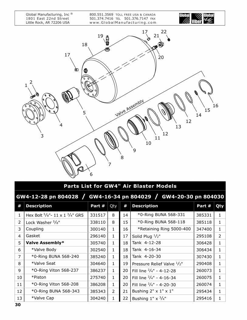
30
Global Manufacturing, Inc ® 800.551.3569 TOLL FREE USA & CANADA1801 East 22nd Street 501.374.7416 TEL 501.376.7147 FAXLittle Rock, AR 72206 USA www.G l oba lManu f a c t u r i ng . c om
4
3
21
2221
1719
18
17 20
8
109
1211
13
1615
1412
5
7
6
Valve A
ssembly
Parts List for GW4" Air Blaster Models
GW4-12-28 pn 804028 / GW4-16-34 pn 804029 / GW4-20-30 pn 804030
# Description Part # Qty # Description Part # Qty
1 Hex Bolt 5⁄8"- 11 x 1 3⁄4" GR5 331517 8 14 *0-Ring BUNA 568-331 385331 1
2 Lock Washer 5⁄8" 338110 8 15 *0-Ring BUNA 568-118 385118 1
3 Coupling 300140 1 16 *Retaining Ring 5000-400 347400 1
4 Gasket 296140 1 17 Solid Plug 1⁄2" 295108 2
5 Valve Assembly* 305740 1 18 Tank 4-12-28 306428 1
6 *Valve Body 302540 1 18 Tank 4-16-34 306434 1
7 *0-Ring BUNA 568-240 385240 1 18 Tank 4-20-30 307430 1
8 *Valve Seat 304640 1 19 Pressure Relief Valve 1⁄2" 290408 1
9 *O-Ring Viton 568-237 386237 1 20 Fill line 3⁄4" - 4-12-28 260073 1
10 *Piston 275740 1 20 Fill line 3⁄4" - 4-16-34 260075 1
11 *O-Ring Viton 568-208 386208 1 20 Fill line 3⁄4" - 4-20-30 260074 1
12 *O-Ring BUNA 568-343 385343 2 21 Bushing 2" x 1" x 1" 295434 1
13 *Valve Cap 304240 1 22 Bushing 1" x 3⁄4" 295416 1

31
Global Manufacturing, Inc ® 800.551.3569 TOLL FREE USA & CANADA1801 East 22nd Street 501.374.7416 TEL 501.376.7147 FAXLittle Rock, AR 72206 USA www.G l oba lManu f a c t u r i ng . c om
8
109
1211
13
1615
1412
7
6
20 17
3
4" x 6" CouplingPN 300164
22
18
17
19
4
21
21
5Valv
e Asse
mbly
Models with 4" x 6" Couplings availableGW6-24-48-4 PN 806248GW6-30-60-4 PN 806260
Parts List for GW6" Air Blaster Models
GW6-24-48 pn 806048 GW6-30-60 pn 806060
# Description Part # Qty # Description Part # Qty
1 Hex Bolt 3⁄4"- 10 x 2" GR5 331517 8 13 *Valve Cap 304260 1
2 Lock Washer 3⁄4" 338112 8 14 *0-Ring BUNA 568-343 385343 1
3 Coupling 300160 1 15 *0-Ring BUNA 568-122 385122 1
4 Gasket 296160 1 16 *Retaining Ring 5000-625 347625 1
5 Valve Assembly 305760 1 17 Solid Plug 1⁄2" 295108 2
6 *Valve Body 302560 1 18 Tank - 6-24-48 307648 1
7 *0-Ring BUNA 568-431 385431 1 18 Tank - 6-30-60 307660 1
8 *Valve Seat 304660 1 19 Pressure Relief Valve 1⁄2" 290408 1
9 *O-Ring Viton 568-254 386254 1 20 Plug - Black Cast 2" 295232 1
10 *Piston 275760 1 21 Fill line 1" - 6-24-48 260076 1
11 *O-Ring BUNA 568-212 385212 1 21 Fill line 1" - 6-30-60 260077 1
12 *O-Ring BUNA 568-436 385436 2 22 Bushing 2 x 1 x 1" 295434 1

32
Global Manufacturing, Inc ® 800.551.3569 TOLL FREE USA & CANADA1801 East 22nd Street 501.374.7416 TEL 501.376.7147 FAXLittle Rock, AR 72206 USA www.G l oba lManu f a c t u r i ng . c om
20
30°
Discharge Pipe
EllipticalOpening
Hopper Wall
0,0
D
C
B
A
w
h
Coordinates and Dimensions of Elliptical Openingsfor
Tangential MountDimensions in Inches
2.5" Pipe 4" Pipe 6" Pipe
X Y X Y X Y
A -1.46 .53 -2.21 .81 -3.39 1.23
B 1.20 3.29 1.55 4.26 2.46 6.75
C 1.46 -.53 2.21 -.81 3.39 -1.23
D -1.20 -3.29 -1.55 -7.26 -2.46 -6.75
Width 3.07 4.70 7.21
Height 7.00 9.07 14.37
Appendix GCoordinates & Dimensions of Elliptical Openings for Tangential Mounts