
AIM 7& 8 units
14
8 th unit: Enterprise resource planning Enterprise resource planning (ERP) integrates internal and external management information across an entire organization, embracing finance/accounting, manufacturing, sales and service, etc. ERP systems automate this activity with an integrated software application. Its purpose is to facilitate the flow of information between all business functions inside the boundaries of the organization and manage the connections to outside stakeholders. [1] ERP systems can run on a variety of hardware and network configurations, typically employing a database to store data. ERP systems typically include the following characteristics: An integrated system that operates in (next to) real time, without relying on periodic updates. A common database, that supports all applications. A consistent look and feel throughout each module. Installation of the system without elaborate application/data integration by the Information Technology (IT) department. Advantages The fundamental advantage of ERP is that integrating the myriad processes by which businesses operate saves time and expense. Decisions can be quicker and with fewer errors. Data becomes visible across the organization. Tasks that benefit from this integration include: [citation needed ] Sales forecasting, which allows inventory optimization Order tracking, from acceptance through fulfillment Revenue tracking, from invoice through cash receipt Matching purchase orders (what was ordered), inventory receipts (what arrived), and costing (what the vendor invoiced) ERP systems centralize business data. Benefits of this include: Eliminates synchronizing changes between multiple systems—consolidatio n of finance, marketing and sales, human resource, and manufacturing applications Enables standard product naming/coding.
-
Upload
tejaswi-geddam -
Category
Documents
-
view
220 -
download
0
Transcript of AIM 7& 8 units

8/7/2019 AIM 7& 8 units
http://slidepdf.com/reader/full/aim-7-8-units 1/14
8 th unit:
Enterprise resource planning
Enterprise resource planning (ERP) integrates internal and external management information across
an entire organization, embracing finance/accounting, manufacturing, sales and service, etc. ERP
systems automate this activity with an integrated software application. Its purpose is to facilitate the flow
of information between all business functions inside the boundaries of the organization and manage the
connections to outside stakeholders.[1]
ERP systems can run on a variety of hardware and network configurations, typically employing a
database to store data.
ERP systems typically include the following characteristics:
An integrated system that operates in (next to) real time, without relying on periodic updates.
A common database, that supports all applications.
A consistent look and feel throughout each module.
Installation of the system without elaborate application/data integration by the Information
Technology (IT) department.
Advantages
The fundamental advantage of ERP is that integrating the myriad processes by which businesses operate
saves time and expense. Decisions can be quicker and with fewer errors. Data becomes visible across
the organization. Tasks that benefit from this integration include:[citation needed ]
Sales forecasting, which allows inventory optimization
Order tracking, from acceptance through fulfillment
Revenue tracking, from invoice through cash receipt
Matching purchase orders (what was ordered), inventory receipts (what arrived),
and costing (what the vendor invoiced)
ERP systems centralize business data. Benefits of this include:
Eliminates synchronizing changes between multiple systems—consolidation of finance, marketing
and sales, human resource, and manufacturing applications
Enables standard product naming/coding.

8/7/2019 AIM 7& 8 units
http://slidepdf.com/reader/full/aim-7-8-units 2/14
Provides comprehensive enterprise view (no "islands of information"). Makes real–time
information available to management anywhere, anytime to make proper decisions.
Protects sensitive data by consolidating multiple security systems into a single structure.[23]
Disadvantages
Customization is problematic.
Re–engineering business processes to fit the ERP system may damage competitiveness and/or
divert focus from other critical activities
ERP can cost more than less integrated and/or less comprehensive solutions.
High switching costs increase vendor negotiating power vis a vis support, maintenance and
upgrade expenses.
Overcoming resistance to sharing sensitive information between departments can divert
management attention.
Integration of truly independent businesses can create unnecessary dependencies.
Extensive training requirements take resources from daily operations.
Connectivity to plant floor information
ERP systems connect to real–time data and transaction data in a variety of ways. These systems are typically
configured by systems integrators, who bring unique knowledge on process, equipment, and vendor solutions.
Direct integration—ERP systems connectivity (communications to plant floor equipment) as part of their product
offering. This requires the vendors to offer specific support for the plant floor equipment that their customers operate.
ERP vendors must be expert in their own products, and connectivity to other vendor products, including competitors.
Database integration—ERP systems connect to plant floor data sources through staging tables in a database. Plant
floor systems deposit the necessary information into the database. The ERP system reads the information in the
table. The benefit of staging is that ERP vendors do not need to master the complexities of equipment integration.
Connectivity becomes the responsibility of thesystems integrator.
Enterprise appliance transaction modules (EATM)—These devices communicate directly with plant floor equipment
and with the ERP system via methods supported by the ERP system. EATM can employ a staging table, Web
Services, or system–specific program interfaces (APIs). The benefit of an EATM is that it offers an off–the–shelf
solution.

8/7/2019 AIM 7& 8 units
http://slidepdf.com/reader/full/aim-7-8-units 3/14
Custom–integration solutions—Many system integrators offer custom solutions. These systems tend to have the
highest level of initial integration cost, and can have a higher long term maintenance and reliability costs. Long term
costs can be minimized through careful system testing and thorough documentation. Custom–integrated solutions
typically run on workstation or server class computers.
Standard protocols—Communications drivers are available for plant floor equipment and separate products have
the ability to log data to staging tables. Standards exist within the industry to support interoperability between
software products.
Concurrent engineering
Concurrent engineering is a work methodology based on the parallelization of tasks (i.e. performing tasksconcurrently). It refers to an approach used in product development in which functions of design engineering,manufacturing engineering and other functions are integrated to reduce the elapsed time required to bring a new
product to the market.
The concurrent engineering method is still a relatively new design management system, but has had the
opportunity to mature in recent years to become a well-defined systems approach towards optimizing engineering
design cycles.[1] Because of this, concurrent engineering has gathered much attention from industry and has been
implemented in a multitude of companies, organizations and universities, most notably in the aerospace industry.
The basic premise for concurrent engineering revolves around two concepts. The first is the idea that all elements of
a product’s life-cycle, from functionality, producibility, assembly, testability, maintenance issues, environmental impact
and finally disposal and recycling, should be taken into careful consideration in the early design phases.
The second concept is that the preceding design activities should all be occurring at the same time, or concurrently.
The overall goal being that the concurrent nature of these processes significantly increases productivity and product
quality, aspects that are obviously important in today's fast-paced market.[3] This philosophy is key to the success of
concurrent engineering because it allows for errors and redesigns to be discovered early in the design process when
the project is still in a more abstract and possibly digital realm. By locating and fixing these issues early, the design
team can avoid what often become costly errors as the project moves to more complicated computational models and
eventually into the physical realm.
As mentioned above, part of the design process is to ensure that the entire product's life cycle is taken into
consideration. This includes establishing user requirements, propagating early conceptual designs, running
computational models, creating physical prototypes and eventually manufacturing the product. Included in the
process is taking into full account funding, work force capability and time, subject areas that are extremely important
factors in the success of a concurrent engineering system. As before, the extensive use of forward planning allows for
unforeseen design problems to be caught early so that the basic conceptual design can be altered before actual
8/7/2019 AIM 7& 8 units
http://slidepdf.com/reader/full/aim-7-8-units 4/14
physical production commences. The amount of money that can be saved by doing this correctly has proven to be
significant and is generally the deciding factor for companies moving to a concurrent design framework.
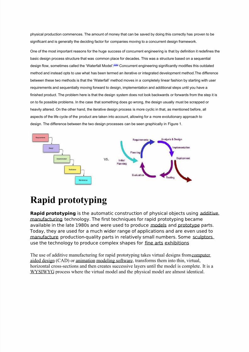
One of the most important reasons for the huge success of concurrent engineering is that by definition it redefines the
basic design process structure that was common place for decades. This was a structure based on a sequential
design flow, sometimes called the ‘Waterfall Model’.[5][6] Concurrent engineering significantly modifies this outdated
method and instead opts to use what has been termed an iterative or integrated development method.The difference
between these two methods is that the ‘Waterfall’ method moves in a completely linear fashion by starting with user
requirements and sequentially moving forward to design, implementation and additional steps until you have a
finished product. The problem here is that the design system does not look backwards or forwards from the step it is
on to fix possible problems. In the case that something does go wrong, the design usually must be scrapped or
heavily altered. On the other hand, the iterative design process is more cyclic in that, as mentioned before, all
aspects of the life cycle of the product are taken into account, allowing for a more evolutionary approach to
design. The difference between the two design processes can be seen graphically in Figure 1.
Rapid prototyping
Rapid prototyping is the automatic construction of physical objects using additive
manufacturing technology. The first techniques for rapid prototyping became
available in the late 1980s and were used to produce models and prototype parts.
Today, they are used for a much wider range of applications and are even used to
manufacture production-quality parts in relatively small numbers. Some sculptors
use the technology to produce complex shapes for fine arts exhibitions
The use of additive manufacturing for rapid prototyping takes virtual designs from computer aided design (CAD) or animation modeling software, transforms them into thin, virtual,
horizontal cross-sections and then creates successive layers until the model is complete. It is a
WYSIWYG process where the virtual model and the physical model are almost identical.

8/7/2019 AIM 7& 8 units
http://slidepdf.com/reader/full/aim-7-8-units 5/14
With additive manufacturing, the machine reads in data from a CAD drawing and lays down
successive layers of liquid, powder, or sheet material, and in this way builds up the model from a
series of cross sections. These layers, which correspond to the virtual cross section from theCAD model, are joined together or fused automatically to create the final shape. The primary
advantage to additive fabrication is its ability to create almost any shape or geometric feature.
The standard data interface between CAD software and the machines is the STL file format. An
STL file approximates the shape of a part or assembly using triangular facets. Smaller facets produce a higher quality surface.
The word "rapid" is relative: construction of a model with contemporary methods can take from
several hours to several days, depending on the method used and the size and complexity of the
model. Additive systems for rapid prototyping can typically produce models in a few hours,although it can vary widely depending on the type of machine being used and the size and
number of models being produced simultaneously.
Some solid freeform fabrication techniques use two materials in the course of constructing parts.The first material is the part material and the second is the support material (to support
overhanging features during construction). The support material is later removed by heat or
dissolved away with a solvent or water.
Traditional injection molding can be less expensive for manufacturing polymer products in highquantities, but additive fabrication can be faster and less expensive when producing relatively
small quantities of parts. 3D printers give designers and concept development teams the ability to
produce parts and concept models using a desktop size printer.
Rapid prototyping is now entering the field of rapid manufacturing and it is believed by many
experts that this is a "next level" technology
Technologies
Rapid prototyping worldwide[2]
The Audi RSQ was made by Audi with rapid prototyping industrial KUKA robots
A large number of competing technologies are available in the marketplace. As all are additive
technologies, their main differences are found in the way layers are built to create parts. Some
are melting or softening material to produce the layers (SLS, FDM) where others are layingliquid materials thermosets that are cured with different technologies. In the case of lamination
systems, thin layers are cut to shape and joined together.
8/7/2019 AIM 7& 8 units
http://slidepdf.com/reader/full/aim-7-8-units 6/14
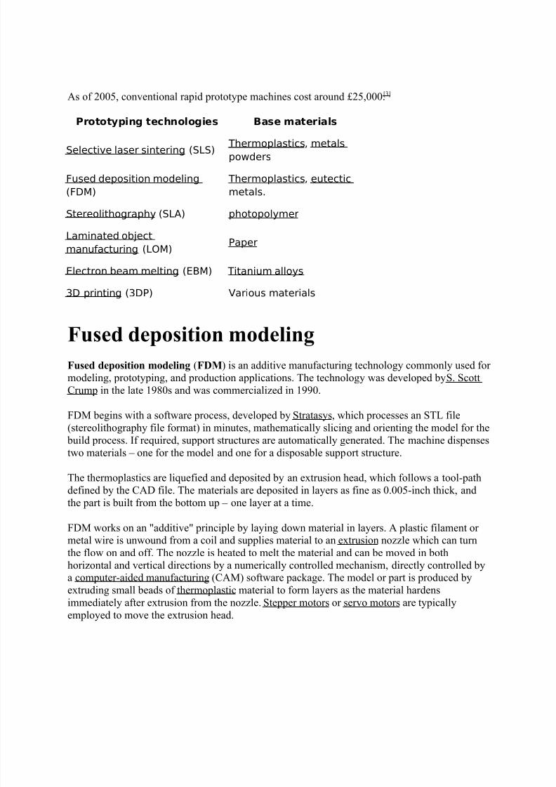
As of 2005, conventional rapid prototype machines cost around £25,000.[3]
Prototyping technologies Base materials
Selective laser sintering (SLS) Thermoplastics, metals
powders
Fused deposition modeling
(FDM)
Thermoplastics, eutectic
metals.
Stereolithography (SLA) photopolymer
Laminated object
manufacturing (LOM)Paper
Electron beam melting (EBM) Titanium alloys
3D printing (3DP) Various materials
Fused deposition modeling
Fused deposition modeling (FDM) is an additive manufacturing technology commonly used for
modeling, prototyping, and production applications. The technology was developed by S. Scott
Crump in the late 1980s and was commercialized in 1990.
FDM begins with a software process, developed by Stratasys, which processes an STL file(stereolithography file format) in minutes, mathematically slicing and orienting the model for the
build process. If required, support structures are automatically generated. The machine dispenses
two materials – one for the model and one for a disposable support structure.
The thermoplastics are liquefied and deposited by an extrusion head, which follows a tool-path
defined by the CAD file. The materials are deposited in layers as fine as 0.005-inch thick, and
the part is built from the bottom up – one layer at a time.
FDM works on an "additive" principle by laying down material in layers. A plastic filament or metal wire is unwound from a coil and supplies material to an extrusion nozzle which can turn
the flow on and off. The nozzle is heated to melt the material and can be moved in bothhorizontal and vertical directions by a numerically controlled mechanism, directly controlled bya computer-aided manufacturing (CAM) software package. The model or part is produced by
extruding small beads of thermoplastic material to form layers as the material hardens
immediately after extrusion from the nozzle. Stepper motors or servo motors are typically
employed to move the extrusion head.
8/7/2019 AIM 7& 8 units
http://slidepdf.com/reader/full/aim-7-8-units 7/14
Several materials are available with different trade-offs between strength and temperature
properties. As well as acrylonitrile butadiene styrene (ABS) polymer, polycarbonates,
polycaprolactone, polyphenylsulfones and waxes. A "water-soluble" material can be used for making temporary supports while manufacturing is in progress, this soluble support material is
quickly dissolved with specialized mechanical agitation equipment utilizing a precisely heated
sodium hydroxide solution.
The term fused deposition modeling and its abbreviation to FDM are trademarked
by Stratasys Inc. The exactly equivalent term, fused filament fabrication
( FFF ), was coined by the members 3D printing
3D printing is a form of additive manufacturing technology where a three dimensional object iscreated by laying down successive layers of material.[1] 3D printers are generally faster, more
affordable and easier to use than other additive manufacturing technologies. 3D printers offer
product developers the ability to print parts and assemblies made of several materials withdifferent mechanical and physical properties in a single build process. Advanced 3D printing
technologies yield models that closely emulate the look, feel and functionality of product prototypes.
A large number of competing technologies are available to do 3D printing. Their maindifferences are found in the way layers are built to create parts. Some methods use melting or
softening material to produce the layers, e.g. selective laser sintering (SLS) and fused deposition
modeling (FDM), while others lay liquid materials that are cured with different technologies. In
the case of lamination systems, thin layers are cut to shape and joined together.
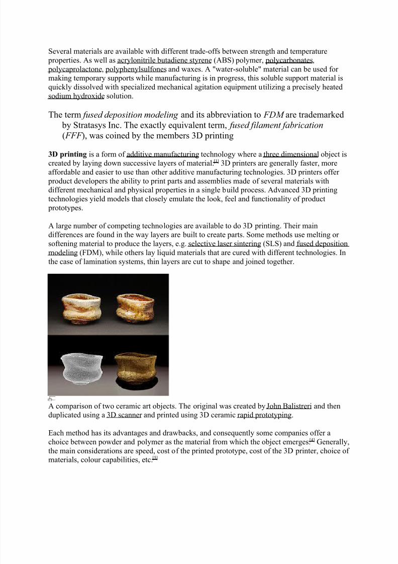
A comparison of two ceramic art objects. The original was created by John Balistreri and thenduplicated using a 3D scanner and printed using 3D ceramic rapid prototyping.
Each method has its advantages and drawbacks, and consequently some companies offer a
choice between powder and polymer as the material from which the object emerges.[4] Generally,
the main considerations are speed, cost of the printed prototype, cost of the 3D printer, choice of materials, colour capabilities, etc.[5]

8/7/2019 AIM 7& 8 units
http://slidepdf.com/reader/full/aim-7-8-units 8/14
One method of 3D printing consists of an inkjet printing system. The printer creates the model
one layer at a time by spreading a layer of powder ( plaster , or resins) and inkjet printing a binder
in the cross-section of the part. The process is repeated until every layer is printed. Thistechnology is the only one that allows for the printing of full colour prototypes. This method also
allows overhangs. It is also recognized as the fastest method.
In digital light processing (DLP), a vat of liquid polymer is exposed to light from a DLP
projector under safelight conditions. The exposed liquid polymer hardens. The build plate thenmoves down in small increments and the liquid polymer is again exposed to light. The process
repeats until the model is built. The liquid polymer is then drained from the vat, leaving the solid
model. The ZBuilder Ultra is an example of a DLP rapid prototyping system.
Fused deposition modeling, a technology developed by Stratasys[6] that is used in traditionalrapid prototyping, uses a nozzle to deposit molten polymer onto a support structure, layer by
layer.
Another approach is selective fusing of print media in a granular bed. In this variation, theunfused media serves to support overhangs and thin walls in the part being produced, reducing
the need for auxiliary temporary supports for the workpiece. Typically a laser is used to sinter
the media and form the solid. Examples of this are selective laser sintering and direct metal laser
sintering (DMLS) using metals.
Finally, ultra-small features may be made by the 3D microfabrication technique of 2-photon
photopolymerization. In this approach, the desired 3D object is traced out in a block of gel by a
focused laser. The gel is cured to a solid only in the places where the laser was focused, due to
the nonlinear nature of photoexcitation, and then the remaining gel is washed away. Feature sizesof under 100 nm are easily produced, as well as complex structures such as moving and
interlocked parts.
[7]
Unlike stereolithography, inkjet 3D printing is optimized for speed, low cost, and ease-of-use,making it suitable for visualizing during the conceptual stages of engineering design through to
early-stage functional testing. No toxic chemicals like those used in stereolithography are
required, and minimal post printing finish work is needed; one need only to use the printer itself
to blow off surrounding powder after the printing process. Bonded powder prints can be further strengthened by wax or thermoset polymer impregnation. FDM parts can be strengthened by
wicking another metal into the part.
A 3D printer works by taking a 3D computer file and using and making a series of cross-
sectional slices. Each slice is then printed one on top of the other to create the 3D object.

8/7/2019 AIM 7& 8 units
http://slidepdf.com/reader/full/aim-7-8-units 9/14
Since 2003 there has been large growth in the sale of 3D printers. Additionally, the cost of 3D
printers has declined.[3] The technology also finds use in the jewellery, footwear, industrial
design, architecture, engineering and construction (AEC), automotive, aerospace, dental andmedical industries
7 th unit:
Adoptive control systems:
In traditional Computer Numerical Control (CNC) systems, machining parameters are
usually selected prior to machining according to handbooks or user’s experience. These
practices tend to select conservative parameters in order to avoid machining failure and
assure product quality specifications. Less conservative practices try to find optimal
machining parameters off-line to increase process productivity after conducting
experimentation. However, variations during the machining process due to tool wear, temperature changes,
vibrations and other disturbances make inefficient
any off-line optimization methodology, especially in high quality machining operations
where product quality specifications are very restrictive. Therefore, to assure the quality of
machining products, reduce costs and increase machining efficiency, cutting parameters
must be optimised in real-time according to the actual state of the process. This optimization
process in real-time is conducted through an adaptive control of the machining process.
The adaptive control applied in machining systems is classified as : Adaptive Control with Constraints (ACC),
Geometric Adaptive Control(GAC), and Adaptive Control with Optimization (ACO). In the ACC systems, process
parameters are manipulated in real time to maintain a specific process variable, such as
force or power, at a constraint value. Typically, ACC systems are utilized in roughing
operations where material removal rate is maximized by maintaining the cutting forces at
the highest possible cutting force such that the tool is not in danger of breaking . In the GAC systems, the economic
process optimization problem is dominated by the need to maintain product quality such as dimensional accuracy
and/or surface finish. GAC systems are typically used in finishing operations with the
objective of maintaining a specific part quality despite structural deflections and tool wear.
Sensor feedback is often employed to measure surface roughness and dimensional quality
between parts and adjustments, so tool offsets and feed overrides can be adjusted for the
next part. In the ACO systems, machine settings are selected to optimize a performance
index such as production time, unit cost, etc. Traditionally, ACO systems have dealt with

8/7/2019 AIM 7& 8 units
http://slidepdf.com/reader/full/aim-7-8-units 10/14
adjusting cutting parameters (feed-rate, spindle speed and depth of cut) to maximise
2 Advances in Robotics, Automation and Control material removal rate subject to constraints such as surface
roughness, power consumption,cutting forces, etc (Venu Gopal & Venkateswara Rao, 2003). Other ACO systems
optimise a multi-objective function which are more practical in industrial applications (Zuperl & Cus,
2005). For example, it is quite often to search the optimal cutting parameters to minimize the
cost of the operation, maximize the production rate and maximize the part quality. ACO
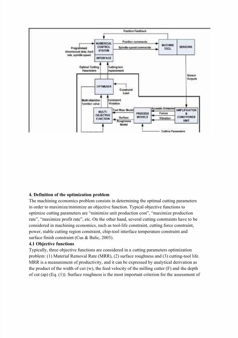
systems are basically composed of several units which integrate the machine-tool system
and the equipment required for acquiring real-time process measurements and adjusting the
cutting parameters. Basically, the ACO system requires a sensor system which provides real-time
data for tool wear diagnosis and part quality prediction. The real-time data are used by
process models previously obtained from experimental data. Tool wear and part quality
models are used in the multi-objective function together with cutting parameters. An
optimizer unit is then applied for searching optimal cutting parameters, and the selected
parameters are sent to the CNC system
In spite of the potential application of ACO systems, their use in industry is limited due to the non-existence of
reliable on-line monitoring systems for tool wear diagnosis and quality prediction. Therefore, the optimal selection
of cutting parameters is usually done off-line for the cutting-tool life-cycle. The off-line parameters optimization is
usually carried out through short cutting experiments which are later used to obtain an empirical model which could
be optimized subjected to some constraints.
8/7/2019 AIM 7& 8 units
http://slidepdf.com/reader/full/aim-7-8-units 11/14
4. Definition of the optimization problem
The machining economics problem consists in determining the optimal cutting parameters
in order to maximize/minimize an objective function. Typical objective functions to
optimize cutting parameters are “minimize unit production cost”, “maximize production
rate”, “maximize profit rate”, etc. On the other hand, several cutting constraints have to be
considered in machining economics, such as tool-life constraint, cutting force constraint,
power, stable cutting region constraint, chip-tool interface temperature constraint and
surface finish constraint (Cus & Balic, 2003).4.1 Objective functions
Typically, three objective functions are considered in a cutting parameters optimization
problem: (1) Material Removal Rate (MRR), (2) surface roughness and (3) cutting-tool life.
MRR is a measurement of productivity, and it can be expressed by analytical derivation as
the product of the width of cut (w), the feed velocity of the milling cutter (F) and the depth
of cut (ap) (Eq. (1)). Surface roughness is the most important criterion for the assessment of

8/7/2019 AIM 7& 8 units
http://slidepdf.com/reader/full/aim-7-8-units 12/14
the surface quality, and it is usually calculated empirically through experiments. Some
research works directly use the empirical relationship presented in Eq. (2), where Vc and f
are the cutting speed and feed rate respectively and k, x1, x2, x3 are empirical coefficients.
Cutting-tool life is the other important criterion for cutting parameters selection, since
several costs such as cutting-tool replacement cost and cutting-tool cost are directly related
with tool life. The relation between the tool life and the parameters is usually expressed by
the well-known Taylor's formula presented in Eq. (3), where KT, α1, α2, α3 are empirical
coefficients.
(1)
(2)
(3)
Adaptive Control Optimization of Cutting Parameters for High Quality Machining Operations
based on Neural Networks and Search Algorithms 7
However, for high quality machining operations using CBN cutting tools, both traditional
surface roughness and tool life equations may not provide a good estimation. Machining a
very low feed speeds produce that additional mechanisms influence the surface roughness
generation such as vibrations, engagement of the cutting tool, built up edge, etc. (Siller et al.,
2008). On the other hand, CBN tools have a different wear process than traditional cuttingtools
such as high speed steels, so Taylor's formula may not be directly applied (Trent &Wright, 2000). For both reasons, other empirical models based on experimental data must be
applied instead of Eqs. (2,3).
For the case study presented in this chapter which is a high quality face milling operation
based on CBN tools, two alternative objective functions were applied. Instead of Ra model,
it is applied the quality loss function described by Eq. (4). Considering a desired Ra value,
the quality loss function is usually applied to estimate the cost of manufacturing with a
quality variation. The loss function is defined as:
(4) where Δ = Ramax - Ratarget with Ramax the maximum Ra defined by specifications and
Ratarget
the Ra desired; V2 is the mean squared deviation as V2 = ((Ratarget - y1)2 + … + (Ratarget -
yn)2)/n , with n the number of samples; and Arework is the part cost if the part is outside
specifications. On the other hand, instead of the traditional Taylor’s formula, it is applied an
empirical model learnt from the experimentation which is defined by the Eq. (5), where f is
8/7/2019 AIM 7& 8 units
http://slidepdf.com/reader/full/aim-7-8-units 13/14
the function learnt.
(5)
5. Parameter optimization based on handbooks
5.1 Description
Cutting tool parameters are traditionally chosen according to handbooks and cutting-tool
data catalogs. For a given cutting-tool and workpiece material, a range of possible
cuttingparameters
are provided. The machinist chooses the parameters within the ranges using
some well-known practices in shop-floor. Some of these practices are:
- Higher cutting speeds increase surface roughness quality but decrease cutting tool life.
- Higher cutting speeds decrease cutting tool life.
- Higher feed rates increase productivity as material removal rate is increased.
- Higher feed rates decrease surface roughness quality.
- Higher feed rates decrease cutting-tool life.
- Higher axial depth of cut increases productivity.
- Higher axial depth of cut decreases cutting-tool life.
- Very low axial depth of cut burns the workpiece surface and generates a low surface
roughness quality and decreases cutting-tool life.
According to the final goal of the machining process, the machinist selects the best
cuttingtool
parameters combination. For example, if the only important constraint is a high cutting
tool life, the machinist will select a low cutting speed, low feed rate and low-medium
axial
depth. Fig. 7a describes the typical optimization process based on handbooks.

8/7/2019 AIM 7& 8 units
http://slidepdf.com/reader/full/aim-7-8-units 14/14
Fig. 7. Off-line cutting parameters optimization.


![Aim: Commented [LN1] · 3/6/2019 · C Translation 4 units left, 2 units down D Translation 2 units right 12. Given the coordinates for each set of vertices, choose the appropriate](https://static.fdocuments.in/doc/165x107/5fab5785aa52bd423178899e/aim-commented-ln1-362019-c-translation-4-units-left-2-units-down-d-translation.jpg)


![Wireless Distributed Architecture for Therapeutic Functional … · distributed FES architecture based on distributed stimulation units (DSU) [8]. The aim being to perform a network-based](https://static.fdocuments.in/doc/165x107/5f96caf27a08a90ab966b0d3/wireless-distributed-architecture-for-therapeutic-functional-distributed-fes-architecture.jpg)