AIM-4SL Hardware Manual - SourceSecurity.com · An access control system provides a means to...
51
This manual contains confidential information and may only be reproduced or distributed with the written consent of Apollo Security Sales, Inc. © 2010 Apollo Security Inc. AIM-4SL Hardware Manual Revision Date: 02 AUG 2010
Transcript of AIM-4SL Hardware Manual - SourceSecurity.com · An access control system provides a means to...

This manual contains confidential information andmay only be reproduced or distributed with thewritten consent of Apollo Security Sales, Inc.
© 2010 Apollo Security Inc.
AIM-4SL HardwareManualRevision Date: 02 AUG 2010

AIM-4SL Hardware Manual
by Apollo Security Inc.
All rights reserved. No parts of this work may be reproduced in any form or by any means - graphic, electronic, ormechanical, including photocopying, recording, taping, or information storage and retrieval systems - without thewritten permission of Apollo Security, Inc.
While every precaution has been taken in the preparation of this document, Apollo Security assumes no responsibilityfor errors or omissions, or for damages resulting from the use of information contained in this document or from theuse of programs and source code that may accompany it. In no event shall the publisher and the author be liable forany loss of profit or any other commercial damage caused or alleged to have been caused directly or indirectly by thisdocument.
© 2010 Apollo Security Inc.
Advanced Electronic Controller For Apollo Access Control Systems

W A R N I N GHIGH VOLTAGE, AC MAIN POWER SHOULD ONLY BE CONNECTED BY QUALIFIED,LICENSED ELECTRICIANS. ALL APPLICABLE LAWS AND CODES MUST BE FOLLOWED. IFTHIS PRECAUTION IS NOT OBSERVED, PERSONAL INJURY OR DEATH COULD OCCUR
Power should not be applied to the system until after the installation has been completed. If thisprecaution is not observed, personal injury or death could occur, and the equipment could bedamaged beyond repair.-Verify that the external circuit breaker which supplies power to the device power supply is turnedoff prior to installation.-Verify that the output voltage of the power supply is within specifications prior to connection to thedevice.
C A U T I O NSeveral important procedures should be followed to prevent electro-static discharge (ESD) damageto sensitive CMOS integrated circuits and modules.
-All transport of electronic components, including completed reader assemblies, should be in staticshield packaging and containers.-Handle all ESD sensitive components at an approved static controlled work station. These workstations consist of a desk mat, floor mat and a ESD wrist strap. Work stations are available fromvarious vendors including the 3M company.
FCC Compliance StatementThis device complies with Part 15 of FCC Rules. Operation is subject to the following twoconditions:
1.This device may not cause harmful interference, and 2.This device must accept any interference received, including interference that may cause undesired operation.
This equipment has been tested and found to comply with the limits for a Class A digital device,pursuant to Part 15 of the FCC Rules. These limits are designed to provide reasonable protectionagainst harmful interference when the equipment is operated in a commercial environment. Thisequipment generates, uses, and can radiate radio frequency energy and, if not installed and usedin accordance with the instruction manual, may cause harmful interference to radiocommunications. Operation of this device in a residential area is likely to cause harmfulinterference in which case the user will be required to correct the interference at his/her ownexpense. The user is advised that any equipment changes or modifications not expressly approvedby the party responsible for compliance would void the compliance to FCC regulations andtherefore, the user's authority to operate the equipment.
IMPORTANT INFORMATION

AIM-4SL Hardware ManualI
© 2010 Apollo Security Inc.
Table of Contents
Part I Introduction 2
................................................................................................................................... 21 Overview
................................................................................................................................... 22 General Features
................................................................................................................................... 23 Modes Of Operation
Part II Hardware Layout 5
................................................................................................................................... 51 Terminal Connectors
................................................................................................................................... 92 DIP Switches
......................................................................................................................................................... 9DIP Switch Tables
......................................................................................................................................................... 10DIP Switch Function
................................................................................................................................... 103 Connectors
......................................................................................................................................................... 10Device Port Communication Driver Socket
......................................................................................................................................................... 10Additional Connectors
................................................................................................................................... 104 LEDs
......................................................................................................................................................... 10Start Up Mode
......................................................................................................................................................... 11Normal Operation
................................................................................................................................... 115 Firmware
................................................................................................................................... 116 Memory Backup
................................................................................................................................... 117 Additional Installation Information
......................................................................................................................................................... 12Mounting Holes
Part III System Wiring 15
................................................................................................................................... 151 Power
................................................................................................................................... 152 Grounding
......................................................................................................................................................... 15DC Ground
......................................................................................................................................................... 15RS-485 Signal Ground (SG)
......................................................................................................................................................... 16Safety (Earth) Ground
......................................................................................................................................................... 16Grounding System
......................................................................................................................................................... 16Grounding Potential Difference Checks Before Connecting
................................................................................................................................... 163 Communication Connection
................................................................................................................................... 174 RS-485 Communications Line
................................................................................................................................... 195 Card Reader Wiring
................................................................................................................................... 206 Reader Input Wiring
......................................................................................................................................................... 21Input Supervision (Overview)
......................................................................................................................................................... 22Door Contact Input (Door Position Switch)
......................................................................................................................................................... 22Exit Pushbutton Input (Request To Exit, REX)
......................................................................................................................................................... 23Auxiliary Alarm Inputs
................................................................................................................................... 237 Output Relay Wiring
......................................................................................................................................................... 23Strike Wiring, General
......................................................................................................................................................... 24Strike Suppression Installation
......................................................................................................................................................... 24Strike Wiring, Internal Relay

IIContents
© 2010 Apollo Security Inc.
......................................................................................................................................................... 26ADA External High Security Relays
.................................................................................................................................................. 26Strike Wiring, External ADA-10/11, High Security Relay
.................................................................................................................................................. 27Additional Output Relay Wiring
.................................................................................................................................................. 28ADA DIP Switches/Jumpers
................................................................................................................................... 298 General Alarm Inputs
......................................................................................................................................................... 29Cabinet Tamper
Part IV Troubleshooting 31
................................................................................................................................... 311 Communications
................................................................................................................................... 312 Reader / Keypad
................................................................................................................................... 313 Input Zones
................................................................................................................................... 314 Output relays
Part V Specifications 33
Part VI Supplemental Figures 35
Part VII Table of Figures 43
Part VIII Revision History 45
Index 46

Part
Introduction
I

2Introduction
© 2010 Apollo Security Inc.
1 IntroductionAn access control system provides a means to replace traditional key and lock systems, which are easy todefeat because of the ease of copying of keys and use by unauthorized personnel. With electronic accesscontrol, the exact areas a person is able to access as well as during what time is configurable through acentral control system. In addition to the power of greater control, a historical record is maintained which isuseful in the case of a system security breach or for other purposes including calculating work time andfacility use costing.
1.1 Overview
The AIM-4SL Downloadable Reader Interface module provides complete connectivity for four card readersand door hardware as well as additional alarm inputs and outputs. The AIM-4SL works in conjunction withthe AAN and AAM series controllers to form a distributed processing network providing access control,integrated alarm monitoring and remote device control and reaction. Typical use of the system is the controlof site access by control of door locking devices associated with card readers and PIN keypads andmaintaining logs of this access for later reporting. Many levels of further integration with building alarm andmonitoring systems, time and attendance systems, and video surveillance systems are also possible.
The AIM-4SL provides interface connections for a variety of card reader technologies, includingproximity, biometric, bar code, and infrared readers. Any card reader with standard Wiegand or mag stripeoutput can be connected to the AIM-4SL. Provided for each of the four readers are exit push button, doorcontact and other general purpose inputs as well as are on-board strike relay and an additional generalpurpose relay outputs. The AIM-4SL communicates with the AAN/AAM controllers to process card reads andalarm input activation. A downloadable card database of up to 20,000 cardholders and storage of up to 7000events allows the AIM-4SL to work independently after initial programming.
1.2 General Features
· Supports 4 readers, keypads or reader/keypad combinations for 4 door control· Full Stand Alone Operation with Local database of 20,000 cards or 7,000 events· Multiple Card Formats· Up to 8 Facility Codes· 8 Relay Outputs (4 Door strike, 4 Auxiliary)· Control of up to 16 ADA-10/11 High Security Relay Output Modules· RS-485 or RS-232· 12 Inputs (4 Door Contact, 4 Exit Pushbutton, 4 Auxiliary)· Field-Replaceable plug-in communication drivers· Real Time Clock· Surface-mount manufacturing technology
1.3 Modes Of Operation
To establish operating configuration, the AIM-4SL interface requires connection to an AAN or AAM controllerwhich is programmed via a software database interface program. Configuration options includingcardholders are stored in a central database and then transmitted via a proprietary encrypted protocol to theAAN/AAM controller. Once programmed, the AAN/AAM controller will communicate to the AIM-4SL interfaceto upload configuration the following configuration information:· Card Reader Data Output Format: Wiegand or Mag Stripe· Strike Time—The time duration that the strike relay will be energized for in the case of an access grant· Held Open Time—After an access grant and a subsequent opening of the door contact, the time in which
the door contact must be closed before an alarm state is reported· Initial Reader Mode—The access mode in which the reader will function upon powering up or when
communication has been interrupted with the AAN/AMM controller. The following modes are supported:
o Card Only—An access request is made by presenting a card to the reader. The data is verified againstthe AIM-4SL database to ensure that the card has a valid Facility Code and Card Number.
o Card or PIN—Access requests are made either by presenting a card or by keying in a PIN (Personal

3 AIM-4SL Hardware Manual
© 2010 Apollo Security Inc.
Identification Number) on a keypad. A card entry is process as in Card Only access mode.o Card & PIN—A card must be read to start the access request. If the card is valid, the user is prompted
to enter the corresponding PIN. The request is granted only if the card and PIN match. o Locked—No access granted. Reader ignores all cards and PIN entries.o Unlocked—Door strike is continuously energized and the door contact input is not monitored. Access is
not controlled.o Facility Code—The entire card contents are read by the AIM-4SL, but only the Facility Code is checked,
and if it matches a Facility Code downloaded from the AAN/AAM controller, access is granted.

Part
Hardware Layout
II

5 AIM-4SL Hardware Manual
© 2010 Apollo Security Inc.
2 Hardware Layout
Reader 1Connection
Reader 2Connection
Reader 4Connection
Reader 3Connection
Power Input
Tamper Input
External Strike Relay Loop
Serial Port
Strike RelayConnections1, 2, 3, 4
Auxilary RelayConnections1, 2, 3, 4
Removable DevicePort Driver Module
DIP Switch
Figure 2.1 AIM-4SL Diagram. Terminal Connectors, DIP Switch, Output Relays, device port driverconnection, and other component locations are shown.
2.1 Terminal Connectors
The AIM-4SL has 9 terminal blocks for connecting power, reader and alarm inputs, and relay outputconnections. The connection terminals are factory equipped with removable screw-down quick connectorswhich are easily removed from the board by firmly grasping the connector and pulling away from the board. If pliers are used to remove the connectors, they should be of the rubber-tipped type. Take care in using anytools near the board not to damage on-board components. The proper location of the quick connectors isoutlined in white on the board.

6Hardware Layout
© 2010 Apollo Security Inc.
AIM-4SL Terminal Connections
Reader ConnectionsPosition Type Label Function
1 Ground (Reader Power) GND
Reader 1 Device Connections
2 Green LED Control GLED
3 Beeper (Buzzer) Control BZR
4 Wiegand Data 1 D1
5 Wiegand Data 0 D0
6 VDC (Reader Power) VDC
7 Red LED Control RLED
8 Yellow LED Control YLED
9 Auxiliary Input Return AUXR Reader 1 Auxiliary Input (NormallyClosed)10 Auxiliary Input AUX
11 Exit Push Button Return EPBR Reader 1 Exit Push Button(Normally Open)12 Exit Push Button EPB
13 Door Contact Return DCR Reader 1 Door Contact(Normally Closed)14 Door Contact DC
15 Ground (Reader Power) GND
Reader 2 Device Connections
16 Green LED Control GLED
17 Beeper (Buzzer) Control BZR
18 Wiegand Data 1 D1
19 Wiegand Data 0 D0
20 VDC (Reader Power) VDC
21 Red LED Control RLED
22 Yellow LED Control YLED
23 Auxiliary Input Return AUXR Reader 2 Auxiliary Input (NormallyClosed)24 Auxiliary Input AUX
25 Exit Push Button Return EPBR Reader 2 Exit Push Button(Normally Open)26 Exit Push Button EPB
27 Door Contact Return DCR Reader 2 Door Contact(Normally Closed)28 Door Contact DC

7 AIM-4SL Hardware Manual
© 2010 Apollo Security Inc.
29 Ground (Reader Power) GND
Reader 3 Device Connections
30 Green LED Control GLED
31 Beeper (Buzzer) Control BZR
32 Wiegand Data 1 D1
33 Wiegand Data 0 D0
34 VDC (Reader Power) VDC
35 Red LED Control RLED
36 Yellow LED Control YLED
37 Auxiliary Input Return AUXR Reader 3 Auxiliary Input (NormallyClosed)38 Auxiliary Input AUX
39 Exit Push Button Return EPBR Reader 3 Exit Push Button(Normally Open)40 Exit Push Button EPB
41 Door Contact Return DCR Reader 3 Door Contact(Normally Closed)42 Door Contact DC
43 Ground (Reader Power) GND
Reader 4 Device Connections
44 Green LED Control GLED
45 Beeper (Buzzer) Control BZR
46 Wiegand Data 1 D1
47 Wiegand Data 0 D0
48 VDC (Reader Power) VDC
49 Red LED Control RLED
50 Yellow LED Control YLED
51 Auxiliary Input Return AUXR Reader 4 Auxiliary Input (NormallyClosed)52 Auxiliary Input AUX
53 Exit Push Button Return EPBR Reader 4 Exit Push Button(Normally Open)54 Exit Push Button EPB
55 Door Contact Return DCR Reader 4 Door Contact(Normally Closed)56 Door Contact DC
Relay Output Connections57 Common C
Door 1 Strike Relay Connection58 Normally Open NO
59 Normally Closed NC
8Hardware Layout
© 2010 Apollo Security Inc.
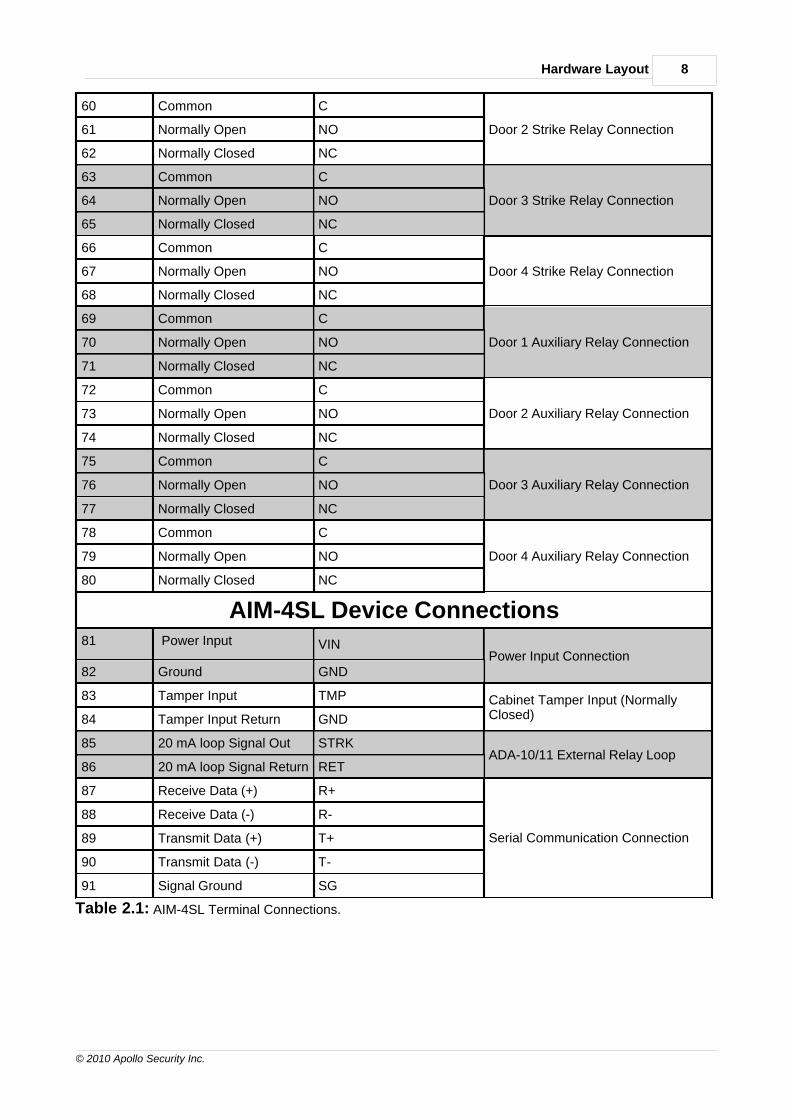
60 Common C
Door 2 Strike Relay Connection61 Normally Open NO
62 Normally Closed NC
63 Common C
Door 3 Strike Relay Connection64 Normally Open NO
65 Normally Closed NC
66 Common C
Door 4 Strike Relay Connection67 Normally Open NO
68 Normally Closed NC
69 Common C
Door 1 Auxiliary Relay Connection70 Normally Open NO
71 Normally Closed NC
72 Common C
Door 2 Auxiliary Relay Connection73 Normally Open NO
74 Normally Closed NC
75 Common C
Door 3 Auxiliary Relay Connection76 Normally Open NO
77 Normally Closed NC
78 Common C
Door 4 Auxiliary Relay Connection79 Normally Open NO
80 Normally Closed NC
AIM-4SL Device Connections81 Power Input VIN
Power Input Connection82 Ground GND
83 Tamper Input TMP Cabinet Tamper Input (NormallyClosed)84 Tamper Input Return GND
85 20 mA loop Signal Out STRKADA-10/11 External Relay Loop
86 20 mA loop Signal Return RET
87 Receive Data (+) R+
Serial Communication Connection
88 Receive Data (-) R-
89 Transmit Data (+) T+
90 Transmit Data (-) T-
91 Signal Ground SG
Table 2.1: AIM-4SL Terminal Connections.

9 AIM-4SL Hardware Manual
© 2010 Apollo Security Inc.
2.2 DIP Switches
The AIM-4SL has one block of DIP switches, with 8 switches. These switches are used to set variousconfiguration options for the interface. It is recommended to power the board down before making anychanges in the DIP switch settings as any changes will not take effect unless the power is cycled.
2.2.1 DIP Switch Tables
Communications Address (SW1)
5 4 3 2 1
OFF OFF OFF OFF OFF 0
OFF OFF OFF OFF ON 1
OFF OFF OFF ON OFF 2
OFF OFF OFF ON ON 3
OFF OFF ON OFF OFF 4
OFF OFF ON OFF ON 5
OFF OFF ON ON OFF 6
OFF OFF ON ON ON 7
OFF ON OFF OFF OFF 8
OFF ON OFF OFF ON 9
OFF ON OFF ON OFF 10
OFF ON OFF ON ON 11
OFF ON ON OFF OFF 12
OFF ON ON OFF ON 13
OFF ON ON ON OFF 14
OFF ON ON ON ON 15
ON OFF OFF OFF OFF 16
ON OFF OFF OFF ON 17
ON OFF OFF ON OFF 18
ON OFF OFF ON ON 19
ON OFF ON OFF OFF 20
ON OFF ON OFF ON 21
ON OFF ON ON OFF 22
ON OFF ON ON ON 23
ON ON OFF OFF OFF 24
ON ON OFF OFF ON 25
ON ON OFF ON OFF 26
ON ON OFF ON ON 27
ON ON ON OFF OFF 28
ON ON ON OFF ON 29
ON ON ON ON OFF 30
ON ON ON ON ON 31
Baud Rate
7 6
1200 OFF OFF
2400 OFF ON
4800 ON OFF
9600 ON ON
Input Monitor Mode
8
Unsupervised OFF
Supervised ON
Table 2. 2: AIM-4SL DIP Switch Settings

10Hardware Layout
© 2010 Apollo Security Inc.
2.2.2 DIP Switch Function
Communications Address—Sets the address that identifies the device on the communications line. Thisnumber must be unique for each device on a single RS-485 communications line. In most systems, thisaddress will correspond to Reader 1 and the following three addresses on the serial line will be reserved forReaders 2-4 which use these ‘virtual’ addresses.
Baud Rate—Specifies the baud rate for the serial line of interface. This setting must be the same for alldevices on the communication line connected to this port.
Input Monitor Mode—Specifies whether all inputs on the interface (Auxiliary inputs, door contacts, exitpush buttons) will be monitored by comparing the resistance value of the input line with the expected value.
ON—In the event of tampering with the input, the interface will report the specific type of error.OFF—Inputs will operate in standard mode.
Table 2.2.1 : DIP Switch Function
2.3 Connectors
The AIM-4SL has several connectors for interfacing with removable components. Take care when installingand removing components in order not to damage pins or sockets. Do not use force greater than gentlepressure when installing any components. Refer to the figure for theexact location of these connectors. The connectors are also labeled on the AIM-4SL in whitelettering on the circuit board.
2.3.1 Device Port Communication Driver Socket
Port Communication Driver Socket: J12
For the functioning of serial communication on the AIM-4SL, a proper communication driver must beconnected to the 12-pin socket. The communication driver module can be either ASM-48 (RS-485, partnumber 430-131) or ASM-23 (RS-232, part number 430-132) depending on the type of communicationrequired on the port. The module should be installed so the long end extends towards the middle of theboard and the mounting holes provided on the AIM-4Sl and ASM align so a plastic stand-off can be attachedto connect the holes. Alternatively, for network configurations, an ENI-100 Ethernet Interface Module can beinstalled in the socket. The module should be installed so that no parts of the ENI-100 extend over theedges of the AIM-4SL. The ENI-100 should be properly fastened with plastic screws and standoffs providedwith the ENI-100. METAL SCREWS AND STANDOFFS SHOULD NOT BE USED TO MOUNT THEENI-100.
2.3.2 Additional Connectors
Additional Connectors/Jumpers: J13, J14
These connectors and jumpers are used for factory configuration and should not be modified or connected inany way unless directed by your technical support.
2.4 LEDs
The AIM-4SL has 2 LEDs for use in monitoring functioning of panel and for diagnosis of problems. TheLEDs function in two modes: startup and normal operation
2.4.1 Start Up Mode
Immediately after powering on the panel, the start-up test will initiate and the results will be displayed on theLEDs. If there are no failures, the test will progress If the panel encounters an error, it will stop with the failedtest and display the LED sequence corresponding to that test. The test sequence and the LED codes are:

11 AIM-4SL Hardware Manual
© 2010 Apollo Security Inc.
Test D14 D15
ROM/Firmware ON OFF
RAM OFF ON
Test OK—Loading Config ON ON
Table 2. 4: AIM-4SL Start up LED Function
2.4.2 Normal Operation
After initialization and self tests, the LEDs will switch to normal operation and will display information aboutthe panel operation.
Heartbeat (D14)—Shows a constant ‘heartbeat’ (0.2 sec ON, 0.8 secOFF) to indicate proper operation of the panel and firmware.
Port Status (D15)—Shows activity on the serial port. Normal activity on the ports will be observed as theLED blinks many times a second or lighted solid, depending on the amount of activity.
2.5 Firmware
The operating program for the AIM-4SL is stored in re-programmable flash memory. In the event that thefirmware must be re-installed or updated, no chips need to be replaced on the panel. The new program canbe loaded from the host via special software. For normal operation it is not necessary to update thefirmware. If this becomes necessary, contact your Apollo support representative. Firmware updating shouldonly be done under the recommendation and guidance of your Apollo technical support representative.
2.6 Memory Backup
The AIM-4SL is equipped with on-board memory to store configuration information and event data. Thismemory, as well as the real-time clock, is provided with back-up power (for up to 5 days) in the event ofprimary power failure. Power is supplied by a special capacitor-based circuit. Battery replacement is neverrequired.
2.7 Additional Installation Information

12Hardware Layout
© 2010 Apollo Security Inc.
2.7.1 Mounting Holes
Four holes are provided for mounting the AIM-4SL. Standoffs should be used when mounting in order toprotect the underside of the circuit board.

13 AIM-4SL Hardware Manual
© 2010 Apollo Security Inc.
Figure 2.7.1 AIM-4SL Mounting Holes. Location of mounting holes for the AIM-4SL is shown inscale. Note that the drawing will not print the exact size of the actual circuit board.

Part
System Wiring
III

15 AIM-4SL Hardware Manual
© 2010 Apollo Security Inc.
3 System Wiring
SPECIAL NOTE: To guard personal safety and avoid damagingequipment it is important to have a full understanding of electricalwiring practices and safety. The following sections provide generalguidelines relating to the AIM-4SL, but are not a substitute for completetraining in dealing with electrical systems!
3.1 Power
Power Connection: TB7
Power is supplied to the AIM-4SL by the voltage connection in terminal block 9 (see Part 2.1 for exactlocations of terminals). The power connection should be 12-28 VDC. Power consumption is 250 mA. TheAIM-4SL is protected from over-current and over-voltage by on-board circuitry.
Take care when selecting a power supply for use with the AIM-4SL. Most power supplies in the market todayprovide good input/output isolation, however those which do not provide isolation (or have high leakagecapacitance), coupled with accidental AC power lines interchange, present serious ground fault problems forinstallers. With ground fault, the signal reference between subsystems may be 115 VAc (230 VAc) apart. Ifthese subsystems are interconnected, the large potential difference will cause equipment damage orpersonal injury. Apollo recommends the use of isolated continuous power supplies only. All Apollo suppliedpower supply assemblies are transformer isolated for safety and to minimize ground loop problems.
In the case of over-current, solid-state fuses integrated on the AIM-4SL panel will ‘trip’ to protect thecomponents of the panel. In many cases, the solid-state fuses will reset automatically when normal currentresumes, however it may be necessary to interrupt the supply of power to allow the fuses to reset.
3.2 Grounding
Special care should be taken when grounding the AIM-4SL controller and other devices connected to it viathe direct communication lines. Each device must be grounded to provide ESD protection, personnel safety,and signal reference for devices which communicate with each other. Grounding the reader provides a goodshield against external transients. There are three types of circuit grounds in systems using Apollo products:DC ground, RS-485 signal ground, and Safety (Earth) ground.
3.2.1 DC Ground
This is typically the minus (-) side of the DC output of the power supply. It is to be connected to the DCground input of all devices being powered by one supply. It must not be connected in any way to any of the 5RS-485 signals or the AC side of the line including Safety (Earth) ground (one connection to Safety (Earth)ground is acceptable, but this connection is usually internal in the host computer and should not beintroduced externally if direct connection is used (RS-232/485)).
3.2.2 RS-485 Signal Ground (SG)
This is the 5th wire used for the RS-485 communications. It is used to provide a common reference betweenall devices on the line and should only be connected to each of the devices' SG input. The SG wire mustnot be allowed to touch any other potential, especially earth ground. The shield drain wire of the RS-485communications cable is commonly used to connect the SG leads together. Usually this wire does not havean electrical insulator. It is important that the SG wire is thoroughly insulated by the installer at all connectionpoints. Improper insulation of this conductor may allow accidental shorting to earth ground through conduitor other metallic components, causing intermittent communications or equipment damage.

16System Wiring
© 2010 Apollo Security Inc.
3.2.3 Safety (Earth) Ground
Safety ground is part of the AC power system. To avoid ground loop current, there must be only ONE pointat which the safety ground connects to the DC ground.
The RS-485 signal ground must be isolated from the safety ground. This means that the RS-485 cable shielddrain wire must be insulated at connection points so that it will NOT accidentally short circuit to the conduit ininstances where the conduit is connected to the safety ground. (See Figure 117)
Please check the applicable regulations and legislation in your country prior to installing the AIM-4SLcontroller and other Apollo products. In the US, the National Electrical Code, as well as other safetyregulations, require that all equipment chassis and/or enclosures be grounded in order to prevent electricalshock hazards. Each device must have a green wire safety ground. The function of the green wire safetyground is to provide a redundant path for fault currents and to insure that the circuit breaker will open in theevent of a fault. In addition, grounding the enclosure provides a path for ESD dissipation, thus protectingsensitive electronic devices. (See Figures 115 and 116)
3.2.4 Grounding System
A grounding system can be viewed as two subsystems: the DC system and the Ground System. The DCsystem consists of all interconnected power supply returns, DC distribution wiring, and load devices. Theprincipal function of the DC system is to provide signal reference for communication. The Ground Systemconsists of all chassis grounds for power supplies and other devices, safety grounds, and AC grounds.Ground connection should be made to avoid ground loop problems. (See Figure 115)
Ideally, there should be ONLY ONE ground return point in a power supply system. In a system with a PC(personal computer), it is likely that the PC already provides the DC Ground connection to the GroundSystem (earth ground). Care must be taken NOT to create more ground connections. In systems withmultiple PCs communicating to Apollo Hardware via direct connection, the ground potential must be thesame for inter-connection, or some form of isolation must be provided.
3.2.5 Grounding Potential Difference Checks Before Connecting
Before a device is connected to an RS-485 subsystem, it must be checked for ground fault. Uncorrectedground fault can damage all devices connected to the RS-485 communication line.
To check if there is ground fault for a new unit, follow the steps below (See Figures 105, 113, 115, 116 and120):
1. Apply power to all devices already successfully connected to the RS-485 line.
2. Power up the new unit, but DO NOT connect it to the RS-485 line.
3. Connect the signal ground (SG) of the RS-485 line through a 10k limiting resistor.
4. Measure the AC and DC voltage across the resistor. There should NOT be more than 1 volt across the resistor. Otherwise find and clear the fault.
5. Connect the new unit to the RS-485 line only if no ground fault is found.
3.3 Communication Connection
The serial connection from the AIM-4SL to controller devices is used to collect requests and information fromthe AIM-4SL to the controller and for the controller to transmit responses to these messages. The AIM-4SLdoes not originate communication on the device communication lines but waits for a poll from the controllerand then establishes communication for configuration. The first communication from the controllerestablishes the presence and proper functioning of the field device, and then the configuration issubsequently sent in the following polling cycles. This polling is done many times a second, with the exactparameters for polling (intervals, timeout, retries) being set by the host software.

17 AIM-4SL Hardware Manual
© 2010 Apollo Security Inc.
3.4 RS-485 Communications Line
The typical connection for field devices (such as the AIM-4SL) on a device port with an Apollo AAN/AAMcontroller is through an RS-485 serial communication line. First, for communication to be possible, thedevice port must have a communications driver installed in the corresponding socket (see Part 2.3). ForRS-485, the ASM-48 Communications Driver module is required. If it is necessary to use RS-232 to connecta device to the AAN-100, contact your Apollo technical support representative for more information.
Overview: The RS-485 standard is an electrical interface for multi-point communication on bus transmissionlines. It allows high speed data transfer over extended distance (4000 ft, 1219 m). Unlike the RS-232C orcurrent loop interfaces, the RS-485 interface allows multiple devices to communicate at high data rates on asingle cable, over long distance. Obviously, the RS-485 interface provides advantages in cost saving forinstallation and improved system performance, but it also brings about issues which would not commonly beseen on systems using RS-232C or current loop interfaces.
Bus Configuration: Communication cables for RS-485 should be laid out in a "Bus topology". This meansthat there should only be two ends to the line and devices should be located directly along this line or (as anexception) on short drops coming from the main line (10 feet max.). The controller can be located at anypoint along the line (See Figure 3.4.1.1). Long stubs (T connection) should be avoided because they creatediscontinuities and degrade signals. DO NOT connect devices in ‘star’ configuration. A star connectioncreates long stubs and causes difficulty in cable termination. The maximum number of field devices on oneRS-485 communications bus is 32. Each field device must have a unique address, and all the devices mustuse the same baud rate, typically 9600bps (both set by the device’s DIP switches, and should have the samecorresponding settings in the host software).
Signal Ground: Using long communication cable with multiple devices often necessitates powering devicesfrom different power sources. This can result in ground faults, which can cause communication problemsand possible equipment damage. Because the RS-485 interface communicates in the base band andprovides no DC isolation, ground fault places devices at different electrical ground levels and causes largeground currents to flow. The possibility of ground fault makes it necessary for careful system planning andinstallation verification. The signal ground (SG) provides a common mode signal reference for thecommunicating devices. Each device must connect its SG to the cable shield drain wire. Failure to use theSG connection may cause communication error. If the environment is known to be electrically noisy, anadditional wire may be used for the signal ground, and the shield can be then grounded as an electric noiseshield.
Termination: Longer communication cable can also create noise and signal reflection problems if propercable is not used or if the cable is not correctly terminated. Therefore, RS-485 must be terminated at bothends. Terminating the line provides more reliable communication by minimizing signal reflection andexternal noise coupling. The factory recommends AC termination to minimize DC loss. Terminatorassemblies with screw terminals (ATM-48, P/N 470-030) are recommended for installation convenience.
Device Wiring: Typical RS-485 consists of four wires: Positive Receive (R+), Negative Receive (R-), PositiveTransmit (T+), Negative Transmit (T-), and Signal Ground (SG). The controller will serve as “Master” on theline and the other field devices (such as the AIM-4SL) as “Slaves”. There can only be one master per line. The transmit lines of the MASTER device are connected to the receive lines of the SLAVE devices and thereceive lines of the MASTER device are connected to the transmit lines of the SLAVE devices.

18System Wiring
© 2010 Apollo Security Inc.
CORRECT
CORRECT
INCORRECT
INCORRECT
Figure 3.4.1.1 RS-485 Bus Configuration. The RS-485 communication line must be laid out in adaisy-chain wiring pattern. Avoid wiring devices in a ‘star’ configuration to avoid reflections and terminationproblems.

19 AIM-4SL Hardware Manual
© 2010 Apollo Security Inc.
Figure 3.4.1.2 RS-485 Device Connections. The AAN-100 serves as the master on the line and thefield devices are slaves. The receive lines of the master are wired to the transmit lines of the slaves, and thereceive lines of the slaves are wired to the transmit of the master.
3.5 Card Reader Wiring
Up to four card readers can be connected to the AIM-4SL. Card readers with standard Wiegand output aresupported, including magnetic stripe, proximity, bar code, smart card, biometric, keypad, etc. It is notnecessary for the readers to be identical on each connection port, i.e. up to four different reader types can beused simultaneously.
Each reader connection consists of connection terminals for VDC Output and Ground, Data 1 Signal, Data 0Signal, Beeper control, and multiple LED control (red, green, and yellow). The wiring to the reader should bemade using 24 AWG shielded cable with 4 twisted pairs (Belden 9504 or equivalent). Do not exceed500 feet (152 m) between the AIM-4SL and reader. Connect the shield drain wire of the cable at the GNDterminal of the appropriate reader connector on the AIM-4SL. Carefully insulate the drain wire with sleevingfor a reliable installation.
Power for the reader connection (VDC) is derived from the power input (VIN) for the AIM-4SL and isdistributed between the four reader connections. Thus, voltage to the reader power connection will roughlyequal the voltage supplied to the AIM-4SL power input. There must be sufficient power to supply the load ofall readers as well as for the AIM-4SL itself (+12 to +24VDC @ 250 mA). If the readers have a greater totalpower requirement, or if there are other wiring concerns, external power supplies should be used to powerthe readers. In this case, only connect the reader power lines to the external power supply; do not connectthe reader to two power supplies.
For basic operation of the reader, at a minimum the Data 0 and Data 1 wires must be connected from thereader to the AIM-4SL and power supplied to the reader. LED and beeper control lines do not have to beconnected, but in this case, the LEDs and beeper may not function on the reader.

20System Wiring
© 2010 Apollo Security Inc.
Brown LEDRed +5 VDCGreen Data 0White Data 1Yellow BuzzerOrange LEDBlack Ground
Yellow LED (If used)
Shield
READER 3 CONNECTION
Door Contact Switch (normally closed)
Exit Push Button (normally open)
Auxilliary Input--Sensor (normally open)
Figure 3.5 AIM-4SL Card Reader and Input Wiring The AIM-4SL supports up to four card readerswhich are connected in standard configuration. For each reader connection there is a door contact input,exit push button input and one axillary input which is displayed here connected to a motion sensor.
3.6 Reader Input Wiring
The each of the four reader inputs on the AIM-4SL has three input circuits (Door Contact, Exit Push Buttonand Auxiliary Alarm 1). These inputs can be configured as UL Grade “B” (unsupervised) or UL Grade “A”(supervised). The selection of supervised / unsupervised is made by changing DIP switch number 8. If in theOFF position, the inputs for all readers are configured as unsupervised, if in the ON position all three inputsare configured as supervised. It is not possible to have both unsupervised and supervised inputs at the sametime, all inputs must be in the same configuration. If the inputs are configured as unsupervised, the doorcontact, exit pushbutton, and both auxiliary alarm contacts should be connected directly to the wiringterminals without using any end of line terminating resistors. If the inputs are configured as supervised, thecontacts must be connected to end of line terminating resistors before being connected to the inputterminals. Use of ATM-30 (part number 470-031) terminator is recommended.

21 AIM-4SL Hardware Manual
© 2010 Apollo Security Inc.
3.6.1 Input Supervision (Overview)
Unsupervised, normally closed inputs will have a short circuit (0 ohms) when the circuit is in the secure stateand an open circuit (infinite ohms) when the circuit is in the unsecured state. This is a simple connection thatdoes not require addition of any resistors. The drawback to this type of connection (unsupervised) is that ifthe two wires touch together (either accidentally or intentional sabotage) the reader will permanently detectthe circuit as being in the secure state. This effectively prevents all alarm generation. This situation is notvery secure and should not be used in any situation that requires maximum security. Unsupervised, normallyopen inputs will have an open circuit (infinite ohms) when the circuit is in the secure state and a short circuit(0 ohms) when the circuit is in the unsecured state. The same situation will occur as stated above if the wiresare cut (permanent secure). Very low security.
The AIM-4SL reader interface allows configuration of the inputs to the “supervised” mode. This is designedto prevent the security breach that is possible using the “unsupervised” mode mentioned above. In thesupervised state, normally closed inputs will have approximately 300 ohms when in the circuit is in thesecure state and 10K ohms when in the unsecured state. If the wires are shorted together or cut(accidentally or intentionally) the reader will instantly detect this (0 ohm or infinite ohm) condition andimmediately report this as a circuit fault. The reader will not confuse this condition with a valid securecondition. Normally open, supervised inputs should be 10K ohms when secure and 300 ohms whenunsecured. Either way, security is greatly enhanced. TO TAKE FULL ADVANTAGE OF THE INCREASEDSECURITY PROVIDED BY INPUT SUPERVISION, THE END OF LINE TERMINATING RESISTORSSHOULD BE ON THE EXTREME END OF THE CABLE, FARTHEST FROM THE READER. In many casesit is possible to mount the resistors inside the housing of the input device.
NOTE: ATM-30 end of line resistors (or an equivalent substitute) are designed to work with the AIM-4SLsupervision values on STANDARD AIM-4SL interfaces. The AIM-4SL is available by special order withcustom resistor values. In the case of improper function of the supervision, verify what type of AIM-4SL isinstalled in the system.
Figure 3.6 Input Supervision. The AIM-4SL reader inputs can be configured for Supervised orUnsupervised. End of line resistors must be used in the supervised configuration in order for the circuits toreport the correct state.

22System Wiring
© 2010 Apollo Security Inc.
3.6.2 Door Contact Input (Door Position Switch)
This is a normally closed input and should have a jumper installed if not used!
Terminal connectors: DC, DCR (See Table 2.1 )
The door contact input is a normally closed input used to monitor the open/closed status of the door. This willtypically be connected to a magnetic sensor in the frame of the door that will provide a short circuit when thedoor is closed and an open circuit when the door is opened. If input supervision is enabled (see Part 3.6.1above), end of line terminating resistors must be installed. The terminating resistors should be installed atthe door contact end (not the reader end) of the cable.
The reader will use this input to detect when the door is opened and when the door is closed. Thisinformation is processed by the reader and used to generate certain alarm messages. If a door is detected tobe opened for no apparent reason (not as a result of a valid card or PIN use or exit button activation), thereader will generate a “Forced Open” message. If the door is opened as a result of a valid access request orexit button activation but not allowed to close within the programmed held open time, a “Held Open” alarmwill be generated.
The reader may also be configured from the host software to allow early strike relay shutoff. Normally theamount of time that the reader will keep the strike relay activated is controlled by the “Strike Time” setting inthe host computer. This is the amount of time a person has to open the door after being granted access.This time is adjustable from 0 to 255 seconds (0 = ½ second). If the strike time is configured for 10 seconds(for example) and the person has already opened and closed the door after 5 seconds, the reader may beconfigured to terminate the normal 10 second strike time early (thus not allowing the door to be openedtwice). If the reader is configured for this early strike shutoff option, it is important that the door contact inputis working properly. If the input is not connected or is malfunctioning and the reader detects that the door isalways open, erroneous alarms will be generated and the Strike Time will always be very short (the readerthinks the people are opening the door quickly), resulting in it being impossible to open the door.
3.6.3 Exit Pushbutton Input (Request To Exit, REX)
The Exit Pushbutton input will be disabled during Reader Tamper and for 1 minute after tampercondition ends!
Terminal Connectors: EPB, EPBR (See Table 2.1 )
The Exit Pushbutton input is used by the reader to inform the reader of a door opening without first using thecard / PIN. Normally, if the reader detects a door open condition without valid use of card or PIN, it willgenerate a “Forced Open” alarm. This alarm must be masked (inhibited) when people use the door to exitfrom the inside of any secured area. The Exit Pushbutton input is used for this purpose. After detecting aclosed circuit of the Exit Pushbutton input, the reader will ignore the door contact input for a period of timeequal to the strike time set for the reader. This allows the people to then open the door for exit without analarm being generated.
In some situations the Exit Pushbutton input should also close the strike relay to allow the door to be openedfrom the inside. This feature is configured in the host software. The reader can be programmed to only maskthe forced open alarm, or to activate the strike relay and mask the forced open alarm. Use of PIR motion exitdevices require that special care be taken in regards to activation of the strike relay. If the reader isconfigured for activation of strike relay on exit, and a PIR is installed on the interior side of the door forautomatic exit activation, if a foreign object is slid under the door from the unsecured side and movedaround, the PIR may be activated. This will mask off all door alarms and release the strike relay, allowingunauthorized entry. Use of Fail Secure Strikes (require power to hold door closed) or Magnetic type locksgenerally will require activation of the strike relay.
Most local fire codes require that exit must be obtainable from all doors regardless of proper operation of theaccess control system and without any prior knowledge of the system operation. This normally means thatsome form of emergency crash bar or manual door release be provided. IT IS THE RESPONSIBILITY OFTHE INSTALLER TO INSURE ALL LOCAL CODES ARE FOLLOWED DURING INSTALLATION.

23 AIM-4SL Hardware Manual
© 2010 Apollo Security Inc.
3.6.4 Auxiliary Alarm Inputs
This is a normally closed input and should have a jumper installed if not used!
Terminal Connectors: AUX, AUXR (See Table 2.1 )
Each reader input on the AIM-4SL includes one Auxiliary Alarm circuit. These inputs may be used for manypurposes that can be configured in the host software. The capabilities will depend on the particular softwaresystem in use. Normally these inputs will be used for monitoring external alarm points such as motiondetectors or glass break detectors. They may also be used as input triggers for Internal Variable andReaction linkage when used with the APACS software. A switch contact may be connected to an Aux Alarminput on reader 4 and the software can be configured to close a relay on reader 23 for example. The fullcapabilities of the Aux Alarm inputs are described in the software manuals. Specifically, reference theInternal Variable and Reactions portions of the APACS software manuals.
In the default configuration of the AIM-4SL, this input will be linked to the corresponding Auxiliary Output i.e.Reader 1 Auxiliary Input-Auxiliary Output 1. Thus, if the input is in alarm state (open) the output will beenergized. This feature is configurable through the host software so that the auxiliary output can respond toother inputs within the system. For more information consult your software documentation.
3.7 Output Relay Wiring
The AIM-4SL has eight output relays onboard, with a dedicated strike relay and an additional Auxiliary Outputrelay for each of the four readers. In addition to these onboard relays, external high security relay modulescan be substituted. The AIM-4SL can support a mixture of use of onboard and external relay modules.
3.7.1 Strike Wiring, General
Typically, doors are held closed and released by one of two methods. An electric door strike is installed in thedoor frame, replacing the mechanical strike plate. This type of strike has a “gate” that is normally held closedand is released by command from the reader. This allows the door to be opened. A second type of lock is aelectro-magnetic lock which is a two piece device mounted on the perimeter of the door. A solid plate ismounted to the door and a electro-magnetic lock is mounted adjacent to the plate on the frame of the door.The electro-magnetic lock firmly holds the plate mounted to the door, holding it closed until the power isremoved by the reader, allowing the door to be opened.
Most electric locks are available in two configurations, Fail-Safe and Fail-Secure. Fail-Safe locks requirepower to hold the door closed and will release the door when power is removed. This type of lock will openthe door if a power outage occurs. This is desirable for doors used as emergency exits. Fail-Secure lockshold the door closed automatically and require power to release the door. This type of lock is desirable forsecuring doors in high security applications. Electro-Magnetic locks are typically only available in theFail-Safe configuration.
Electric locks are also available in a range of operating voltages. 12 volts DC or 24 volts DC are the mostcommon. AC power strikes are also available but are not widely used because of the difficulty in connecting suppression circuitry (see Part 3.6.5.2) and the inability of providing battery backup power in the event ofpower failure. If a 12 or 24 volt DC lock is selected, the same power supply used to power the lock may beused to power the reader. UNDER NO CIRCUMSTANCES SHOULD AC POWER BE APPLIED TO THEAIM-4SL READER INTERFACE!
A typical electric door lock (strike) will require approximately 250 mA. (.250 amps) to control. The relaycontacts on all Apollo relays are capable of switching up to 24 volts DC at up to 2 amps. If the particularlocking device requires more that 2 amps to control, a separate, external relay capable of switching therequired amount of current must be installed.
The AIM-4SL provide two methods of strike control for each reader. The first method is by use of the internalstrike relay. Four such relays are provided on the AIM-4SL—one for each reader input. Each is rated forswitching 2 amps at up to 24 volts DC. Connection of this internal relay is covered in Part 3.5.3 The readeralso has the capability of connecting external, high security relay modules (ADA-10/11) for control of theelectric lock as well as other outputs. Connection of these external relays is covered in the following sections.

24System Wiring
© 2010 Apollo Security Inc.
Use of the internal relay provides for a simple, cost effective method for connection of the door strike with areduced level of security. If someone physically access the strike relay wiring, they may be able to releasethe door. The external relays (ADA-10/11) are designed to eliminate this possible security breach.
Wiring between the strike power supply, strike relay (internal or external) and the electric lock should be ofsufficient gauge to prevent excessive voltage drop under all circumstances.
ALL ELECTRIC LOCKS MUST HAVE A SUPPRESSION CIRCUIT INSTALLED TO PREVENT EXCESSIVEINTERFERENCE WITH OTHER SYSTEM COMPONENTS WHEN THE POWER IS REMOVED. SEE THEFOLLOWING SECTION FOR INFORMATION ON SUPPRESSION INSTALLATION.
3.7.2 Strike Suppression Installation
Most electric locks consist of several components, one of which is usually a coil of wire that acts as anelectro-magnet to either release the door (Fail-Secure) or hold the door closed (Fail-Safe). This coil of wireacts as a large inductor. When DC power is applied to a large inductor, energy is stored in the inductor.When the circuit is broken (power is removed) this stored energy is converted to a very large voltage andattempts to travel down the wires connected to the strike. IF SOME METHOD IS NOT UTILIZED TOREDUCE OR SUPPRESS THIS VERY LARGE VOLTAGE, IT CAN CAUSE COMMUNICATIONSPROBLEMS, PERMANENT DAMAGE TO THE STRIKE RELAY, AND PERMANENT DAMAGE TO OTHERSYSTEM COMPONENTS!
The most common method of suppression used on DC power strikes is installation of a reverse biased diodeas close a possible to the strike itself. Any type of general purpose diode (1N4001 – 1N4006, etc.) will work
AC powered locks will not allow use of a diode for suppression. There are available suppressors for use withAC powered locks called Metal Oxide Varistors (MOV’s). These are sometimes included with the lock. If youwish to use AC powered strikes and a suitable suppressor is not supplied with the lock, you must contact themanufacturer of the lock for information on obtaining a suitable suppressor. Connection of the suppressorshould follow the instructions provided with the lock.
3.7.3 Strike Wiring, Internal Relay
The AIM-4SL Reader Interface includes internal relays for door strike control for each of the four readerinputs. This relay is capable of switching up to 24 volts at up to 2 amps. If the lock installed on the doorrequires more than 2 amps to control, an external relay must be provided. The power that is provided to thelocking device (strike) through this relay may be connected to the same power supply that is providing powerthe reader if the strike requires 12 or 24 volts DC. IF THE STRIKE REQUIRES A VOLTAGE OTHER THAN12 OR 24 VOLTS DC OR ANY AC VOLTAGE, A SEPARATE POWER SUPPLY MUST BE USED.
Use of the internal strike relay allows for simple connection of the door strike without requiring installation ofexternal ADA-10/11 relay modules. This will result in reduced installation costs at the expense of increasedsecurity. Use of the external, high-security, relay modules (ADA-10/11) will provide increased security on thestrike output.
The diagram below illustrates connection of a DC powered, Fail-Secure, door strike. This type of strikerequires power to release the door. The power will be supplied through the normally open (NO) relay contactof the strike relay. No power will be provided to the strike until the reader activates the internal relay. Thereader will activate the relay as a result of a valid access request (card swipe, card swipe plus valid PIN,valid PIN entry only, etc.). The reader will also permanently activate the strike relay if commanded by thehost software to be “unlocked”. The reader may also be configured to activate the relay if the exit pushbuttonis depressed. Some software systems may allow configuration of this feature (activate strike relay on exitpushbutton) and others may not.

25 AIM-4SL Hardware Manual
© 2010 Apollo Security Inc.
Strike
+
_
Strike PowerMay Be Same As Reader
if 12 or 24 VDC Install Supressor at Strike (see above text)
+_Common
"C"
Normally Open"NO"
Diagram 3.7.3.1 Strike Wiring - Fail Secure
The diagram below illustrates connection of a DC powered, Fail-Safe, door strike. This type of strike requirespower to hold the door closed. The power will be supplied through the normally closed (NC) relay contact ofthe strike relay. Power will be provided to the strike until the reader activates the internal relay. The readerwill activate the relay as a result of a valid access request (card swipe, card swipe plus valid PIN, valid PINentry only, etc.). The reader will also permanently activate the strike relay if commanded by the host softwareto be “unlocked”. The reader may also be configured to activate the relay if the exit pushbutton is depressed.Some software systems may allow configuration of this feature (activate strike relay on exit pushbutton) andothers may not.
Strike
+
_
Strike PowerMay Be Same As Reader
if 12 or 24 VDC Install Supressor at Strike (see above text)
+_Common
"C"
Normally Closed"NC"
Diagram 3.7.3.2 Strike Wiring - Fail Safe

26System Wiring
© 2010 Apollo Security Inc.
3.7.4 ADA External High Security Relays
12 VdcPower Supply
+ -
Apollo Card ReaderInterface
OUTRET/GND
+
-
DoorStrike
IN+
IN-
V I N
GND
NC
N 0
C DIO
(DC Powered)
Figure 3.7.3: ADA-11 Loop and Strike Wiring. An example showing wiring with two ADA-11swith a DC Powered Door Strike. The strike is wired Fail-Secure, thus power is supplied to the strike onlywhen the relay is activated. The ADA-10 is wired in a similar fashion but instead of wiring to terminals, wiringmust be connected to the special connector of the ADA-10.
3.7.4.1 Strike Wiring, External ADA-10/11, High Security Relay
Use of the internal relays provided on the AIM-4SL reader provides a possible security breach as describedabove. To prevent the possibility of illegally releasing the door by smashing open the reader and bypassingthe internal relay, external, high security relays may be installed. The ADA-10 and ADA-11 relay module aredesigned for this purpose. These relays are not included with the AIM-4SL and must be purchasedseparately.
The purpose of the ADA-10/11 high security relay is to supervise (protect) the wiring between the reader andthe electric strike. IF THERE IS A POSSIBILITY OF AN INTRUDER ILLEGALLY GAINING ACCESS TOTHESE WIRES, THE ADA-10/11 SHOULD BE USED. If someone illegally gains access the wires betweenthe reader and the ADA-10/11, it is not possible to cause the door to release. The information passing alongthese wires is encoded, digital data, not a simple short or open circuit that is easily compromised.
The wiring between the ADA-10/11 module and the electric strike itself is not protected. To maximize theincreased security of the ADA-10/11 module, the module should be mounted as close to the actual electricstrike as possible, minimizing the length of the unprotected wires.
The ADA-10 module is a potted module with an 8 position connector on the end of a short ribbon cable.Optional connectors and mounting tools (ATL-10, 490-040) may be purchased from Apollo
The ADA-10 has several jumpers on the top surface that must be cut to configure the operation of the relay.When cutting the jumpers, it is important to only cut the jumpers at the top of the loop and bend the twohalves apart to prevent them from touching. DO NOT CUT THE JUMPERS FLUSH WITH THE SURFACEOF THE ADA-10 AS IT MAY BE NECESSARY RECONNECT THEM LATER IF THE WRONG JUMPERS

27 AIM-4SL Hardware Manual
© 2010 Apollo Security Inc.
HAVE BEEN CUT. It may be necessary to wrap the ADA-10 with insulated tape to prevent the ends of thejumpers from shorting to any external metal objects.
The ADA-11 module is identical in function to the ADA-10 module. It is a smaller, non-potted circuit boardthat includes a plastic, “U Channel”, mounting track. Unlike the ADA-10 the power input does not have to beconfigured for 12 or 24 volt operation, it automatically works on 12 or 24 volts DC. Also in place of thejumpers that require cutting on the ADA-10 module, the ADA-11 has DIP switches which are easier toreconfigure if set incorrectly. Wiring is connected to the ADA-11 using screw terminal blocks instead of thespecial connectors utilized on the ADA-10.
BECAUSE THE ADA-11 IS A NON-POTTED MODULE, IF THE RELAY IS TO BE INSTALLED IN A AREAOF EXTREME ENVIRONMENTAL CONDITIONS, THE ADA-10 IS A BETTER CHOICE. The ADA-11 circuitis coated with a protective, environmental seal, but it is not as well protected as the potted, ADA-10 module.
3.7.4.2 Additional Output Relay Wiring
Each reader input of the AIM-4SL has the capability of controlling 3 output relays in addition to the strikerelay. There are a total of five output relays available. The internal strike relay, an external strike relay, andthe three extra output relays. The two strike relays (internal and external) perform the exact same functions,releasing the door when required. The extra three relays available are defined as Local Alarm, Aux Out 1,and Aux Out 2.
The function of the Local Alarm relay is pre-programmed in the firmware of the reader and cannot bemodified. The reader will activate this relay whenever any of the following conditions exist:
Door Forced Open (Reader Detects the Door Contact Input Open Illegally)Door Held Open (Reader Detects the door has not closed after legal entry)Auxiliary Alarm (Either of the Auxiliary Alarm inputs are opened)Reader Tamper (AIM-4SL Tamper Input is opened)
Because control of the local alarm relay is completely self contained within the reader interface, this relay willactivate anytime the above conditions occur, regardless of proper functioning of the other components in thesystem. This relay does not require communications to be working, the controller to be functioning, the PC tobe operating, or the software to be running. The only thing required for the local alarm relay to operate ispower (battery backed up UPS power supplies may be used). Because of this extremely reliable operation,the Local Alarm relays are often used as a redundant backup to other system functions in highly criticalareas. Some typical uses for the Local Alarm relay are as a standalone siren above certain doors,connection into other alarm systems, and small bell to signal Held Open to get the people holding the dooropen to close it.
FOR PROPER OPERATION OF THE LOCAL ALARM RELAY, ALL UNUSED INPUTS MUST BETERMINATED. In the Unsupervised mode, jumpers should be connected to any unused Aux Alarm or DoorContact Input. If the reader is being used in the supervised mode, 300 ohm resistors or ATM-30 terminatorswith a jumper between inputs 1 and 2 should be connected to all unused inputs. For information, see thesection regarding input supervision.
The Aux Out 1 and 2 relays are programmable relays that require programming to configure their operation.They may be linked to other system alarms or events to trigger a siren or bell. An example may be toconnect a siren to a Aux Out relay connected to a reader near the security Supervisor's office and configurethe software to activate this relay (siren) whenever any door in the entire system is Forced Open. The actualcapabilities of the Aux Out relays are dependant on the software system being used and the type ofcontroller.
The use of any of these three relay capabilities requires addition of external ADA-10/11 relay modules.THESE RELAYS ARE NOT PROVIDED WITH THE AIM-4SL AND MUST BE PURCHASED SEPARATELY.The ADA-10 relay module is a potted module suitable for use in areas where extreme environmentalconditions may be present, the ADA-11 is a smaller, non-potted version that should not be used in areas ofextreme environmental conditions. See the above sections for more information about the ADA-10 andADA-11 external, high-security relay modules.
28System Wiring
© 2010 Apollo Security Inc.
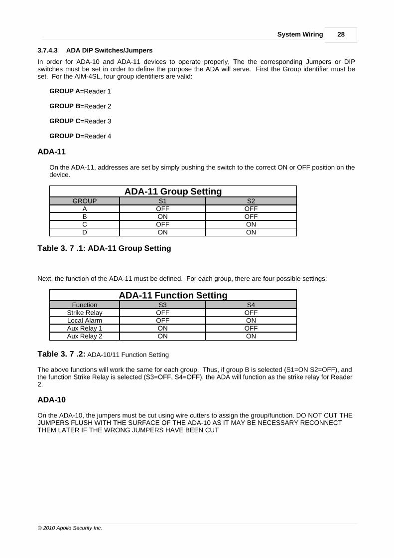
3.7.4.3 ADA DIP Switches/Jumpers
In order for ADA-10 and ADA-11 devices to operate properly, The the corresponding Jumpers or DIPswitches must be set in order to define the purpose the ADA will serve. First the Group identifier must beset. For the AIM-4SL, four group identifiers are valid:
GROUP A=Reader 1
GROUP B=Reader 2
GROUP C=Reader 3
GROUP D=Reader 4
ADA-11
On the ADA-11, addresses are set by simply pushing the switch to the correct ON or OFF position on thedevice.
ADA-11 Group SettingGROUP S1 S2
A OFF OFFB ON OFFC OFF OND ON ON
Table 3. 7 .1: ADA-11 Group Setting
Next, the function of the ADA-11 must be defined. For each group, there are four possible settings:
ADA-11 Function SettingFunction S3 S4
Strike Relay OFF OFFLocal Alarm OFF ONAux Relay 1 ON OFFAux Relay 2 ON ON
Table 3. 7 .2: ADA-10/11 Function Setting
The above functions will work the same for each group. Thus, if group B is selected (S1=ON S2=OFF), andthe function Strike Relay is selected (S3=OFF, S4=OFF), the ADA will function as the strike relay for Reader2.
ADA-10
On the ADA-10, the jumpers must be cut using wire cutters to assign the group/function. DO NOT CUT THEJUMPERS FLUSH WITH THE SURFACE OF THE ADA-10 AS IT MAY BE NECESSARY RECONNECTTHEM LATER IF THE WRONG JUMPERS HAVE BEEN CUT

29 AIM-4SL Hardware Manual
© 2010 Apollo Security Inc.
ADA-10 Group SettingGROUP G1 G2
A NOT CUT NOT CUTB NOT CUT CUTC CUT NOT CUTD CUT CUT
Next, the function of the ADA-11 must be defined. This is done by cutting THREE of the four jumpers forOutput Select on the ADA-10. For each group, there are four possible settings:
ADA-10 Function SettingFunction 1 2 3 4
Strike Relay NOT CUT CUT CUT CUTLocal Alarm CUT NOT CUT CUT CUTAux Relay 1 CUT CUT NOT CUT CUTAux Relay 2 CUT CUT CUT NOT CUT
The above functions will work the same for each group. Thus, if group B is selected (G1=NOT CUTG2=CUT), and the function Strike Relay is selected (1=NOT CUT 2=CUT 3=CUT 4=CUT), the ADA willfunction as the strike relay for Reader 2.
For your convenience, the settings for the ADA-10 are printed on the product label affixed to the housing. Itis also reproduced in Part 6 of this manual.
3.8 General Alarm Inputs
The AIM-4SL provides one general alarm input. The wiring to the input should be made with twisted pair 24AWG wire. If these input is not used, it should be ‘jumpered’ using a 1” (25 mm) long piece of wireconnecting the two terminals to form a closed circuit. This will prevent an alarm condition being reported tothe host.
3.8.1 Cabinet Tamper
This is a normally closed input and should have a jumper installed if not used!
Cabinet Tamper Input: TB19
This input is for connection to a switch located on the cabinet in which the AIM-4SL is installed to detectunauthorized access to the panel. This is a normally-closed contact. In the event of a tamper condition, theexit push buttons will not function on all 4 reader connections. This condition will last until one minute afterthe tamper has ended. This feature restricts the ability to have easy control of all the doors by merelyshorting the EPB input.

Part
Troubleshooting
IV

31 AIM-4SL Hardware Manual
© 2010 Apollo Security Inc.
4 Troubleshooting
4.1 Communications
The first thing that must be verified at the card reader is the RS-485 communications. If the reader is unablethe communicate to the controller, most other functions will not work. Communications should be verifiedobserving the port activity LED (D15), which will blink when communication is active (see Part 2.4).
4.2 Reader / Keypad
The reader function can be verified after communications are functioning properly. The host system must beconfigured for each of the readers on the AIM-4SL to be used, and with the correct card format. The cardformat is determined by the actual cards that will be used. After configuring the card format at the host,placing a card in front of the reader should generate an access message on the host computer. If themessage is “Access Denied” the reason for the message will indicate further steps to be performed. “AccessDenied – Wrong Facility Code” will also display the actual facility code on the card. This information shouldthen be entered to the host computer system. “Access Denied – Not in File” will display the actual cardnumber of the presented card. This card should then be added into the employee database of the hostsystem.” Access Denied – Access Level Error” indicates that the cards is entered into the system but theAccess Level assigned to the card does not allow access to the particular door at this time.
On readers with integral keypads, the keypad may be verified by setting the reader into the Card and PINmode. After presenting a valid card, the reader should flash the yellow LED (if installed reader supports 3color LEDs). This indicates the reader is waiting for a Pin entry. Enter a valid PIN using the keypad and pressthe “ENTER” key. Access should be granted.
4.3 Input Zones
All alarm inputs should next be verified. Opening the Door Contact input should generate an immediate“Forced Open” alarm. Closing the Exit Pushbutton input should release the strike relay. NOTE: the ExitPushbutton input will not function if the reader interface is in tamper (Tamper Contact=Open) and also oneminute after the tamper condition is secured. The reader may also be configured (via the host) to not activatethe strike relay when the Exit Pushbutton is depressed. In all cases the reader should not report “ForcedOpen” immediately after pressing the Exit Pushbutton. The Aux Alarm inputs (if used) can be verified next.Some system will not allow use of the second Aux alarm. Opening the Aux alarm input should result in amessage on the host system. Unused Aux alarm inputs should be terminated.
4.4 Output relays
The internal strike relays should energize any time a valid card (or PIN) is presented and the message“Access Granted” appears on the host. The reader may be set to the “Unlocked” mode at the host topermanently energize the relay for test purposes. Any external, high-security, ADA-10.11 relay modulesshould also be verified.

Part
Specifications
V

33 AIM-4SL Hardware Manual
© 2010 Apollo Security Inc.
5 SpecificationsRelay Specifications:
Coil: 12VdcContacts: 2A @ 24Vdc
0.5A @ 125Vac
Power Requirements:
+12 to +24Vdc @ 250mA
Dimensions:
7.5 in x 5.5 in (19 x 14 cm)
Environment:
Operating Temperature: -0 to 50° CStorage Temperature: -40 to 85° CRelative Humidity: 0 to 95%, non-condensing

Part
Supplemental
Figures
VI

35 AIM-4SL Hardware Manual
© 2010 Apollo Security Inc.
6 Supplemental Figures

36Supplemental Figures
© 2010 Apollo Security Inc.

37 AIM-4SL Hardware Manual
© 2010 Apollo Security Inc.

38Supplemental Figures
© 2010 Apollo Security Inc.

39 AIM-4SL Hardware Manual
© 2010 Apollo Security Inc.

40Supplemental Figures
© 2010 Apollo Security Inc.

41 AIM-4SL Hardware Manual
© 2010 Apollo Security Inc.

Part
Table of Figures
VII

43 AIM-4SL Hardware Manual
© 2010 Apollo Security Inc.
7 Table of FiguresNumber Description Page
2.1 AIM-4SL Diagram 52.7.1 AIM-4SL Mounting Holes 13
3.4.1.1 RS-485 Bus Configuration 183.4.1.2 RS-485 Device Connections 19
3.5 AIM-4SL Card Reader & Input Wiring 203.6 Input Supervision 21
3.7.3.1 Strike Wiring - Fail Secure 253.7.3.2 Strike Wiring - Fail Safe 253.7.3 ADA-11 Loop and Strike Wiring 26181 AIM-4SL PCB Assembly 35105 Signal Ground 36113 Fault Caused by Incorrect AC Power Wiring 37115 Ground Connection 38116 Ground Fault Test Between Sub-systems 39117 Overview of Ground / RS-485 Communication Wiring 40120 Ground Check 41

Part
Revision History
VIII

45 AIM-4SL Hardware Manual
© 2010 Apollo Security Inc.
8 Revision History
REVISION HISTORY
Revision Date Description of changes EditorB 26 AUG 2006 Rewrite and accuracy review R. Burnside
B.1 7 MAY 2007 Update ADA-11 DIP Switch Settings R. BurnsideB.2 2 AUG 2010 Correct RS-485 Bus Configuration Figure
3.4.1.1; Add Mounting Holes Diagram 2.7.1R. Burnside

Index 46
© 2010 Apollo Security Inc.
Index
- A -AC power system 16
Access Control 2
APACS 23
ASM-23 10
ASM-48 10
- B -Batteries 33
Battery 11
Baud Rate 10
Bus Configuration 17
- C -Capacitor (Memory Backup) 11
Connectors 10
- D -DC ground 15
Device Port 10, 17
Dimensions 33
- E -Error codes 10
- F -Firmware 11
- G -Ground connections 15
Faults 15, 16
Saftey (Earth) Ground 16
- H -Heartbeat 11
- I -Isolation (Power) 15
- L -LEDs 5, 10, 19, 31
- M -Memory Backup 11
- O -On-board memory 11
Operating Environment 33
- P -Power supply 15
- R -RS-485 17
Device Drivers (ASM-48) 10
Signal Ground 15
- S -Self Test 10
Signal Ground 17
Specifications 33
Start Up Mode 10
Supervision (Input) 21
- T -Terminal Connectors 5
Termination 17
Test sequence 10