Protecting Your Business Globally - David Snead, i2Coalition
Upload
nguyencongCategory
view
213download
0
43rd AIAA Aerospace Sciences Meeting and Exhibit AIAA 2005-0814 10-13 January 2005, Reno, Nevada
This material is declared a work of the U.S. Government and is not subject to copyright protection in the United States.
Configurable Air Transport
James Michael Snead* Air Force Research Laboratory, Wright-Patterson AFB, OH 45433
This paper describes a concept of a large flying fuselage transport aircraft that carries the cargo or missionized payload in several large, detachable modules instead of carrying this cargo or payload internally as in current aircraft designs. The paper addresses the application of this concept to the global military airlift missions of air refueling, materiel transport, and persistent air power projection. The paper concludes with a brief discussion of the extension of this module-based aircraft design to other emerging military and commercial air transport needs.
Nomenclature ton = 2,000 lb or 907 kg
I. Introduction common characteristic of all production transport aircraft has been the use of the classic wing-fuselage-tail design incorporating a cargo compartment permanently a part of the tubular fuselage. This “constraint” has
resulted in aircraft generally dedicated to a particular set of mission capabilities frozen at the time the aircraft is manufactured or, as in the case of installing passenger-to-cargo conversion kits, when an existing aircraft is remanufactured into a different mission configuration.
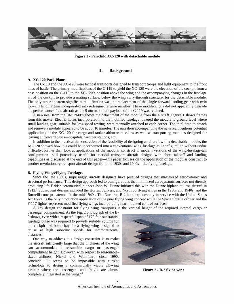
In the late 1940s Fairchild addressed the operational constraints imposed by traditional fixed aircraft configurations with an experimental variant of the United States Air Force C-119 aircraft. To build this XC-120, the C-119 was modified to replace the fuselage section below the wing carry-through structure with a hardback capable of carrying a detachable module. Referred to as the “Pack Plane,” the XC-120 demonstrated the feasibility of a different and more mission-flexible transport aircraft design approach where a transport aircraft’s mission capabilities can be expanded through the use of an easily changed module where the module’s mission capabilities, e.g., passenger, cargo, bomber, tanker, etc., defines the aircraft’s mission capabilities.
While the XC-120 modular aircraft did not proceed into development, it remains an interesting and potentially revolutionary idea. This paper pursues the application of this concept to modern air transport systems. It briefly summarizes previous applicable flying wing/fuselage design efforts, explores the application of the flying wing/fuselage concept to modern modular transport aircraft, discusses possible design approaches for a long-range air transport aircraft, and discusses potential acquisition and operational advantages of such an aircraft for commercial and military transport operations. The paper concludes with a brief discussion of the potential extension of this module-based aircraft design to smaller fixed-wing and rotor aircraft. * P.E., Aerospace Engineer, AFRL/XPA, [email protected], Senior Member
A
American Institute of Aeronautics and Astronautics
2
II. Background
A. XC-120 Pack Plane The C-119 and the XC-120 were tactical transports designed to transport troops and light equipment to the front
lines of battle. The primary modifications of the C-119 to yield the XC-120 were the elevation of the cockpit from a nose position on the C-119 to the XC-120’s position above the wing and the accompanying changes in the fuselage aft of the cockpit to provide a mating surface, below the wing carry-through structure, for the detachable module. The only other apparent significant modification was the replacement of the single forward landing gear with twin forward landing gear incorporated into redesigned engine nacelles. These modifications did not apparently degrade the performance of the aircraft as the 9 ton maximum payload of the C-119 was retained.
A newsreel from the late 1940’s shows the detachment of the module from the aircraft. Figure 1 shows frames from this movie. Electric hoists incorporated into the modified fuselage lowered the module to ground level where small landing gear, suitable for low-speed towing, were manually attached to each corner. The total time to detach and remove a module appeared to be about 10 minutes. The narration accompanying the newsreel mentions potential applications of the XC-120 for cargo and tanker airborne missions as well as transporting modules designed for leaving at forward bases—hospitals, weather stations, etc.
In addition to the practical demonstration of the feasibility of designing an aircraft with a detachable module, the XC-120 showed how this could be incorporated into a conventional wing-fuselage-tail configuration without undue difficulty. Rather than look at applications of the modular construct to modern versions of the wing-fuselage-tail configuration—still potentially useful for tactical transport aircraft designs with short takeoff and landing capabilities as discussed at the end of this paper—this paper focuses on the application of the modular construct to another revolutionary transport aircraft design from the 1930s and 1940s—the flying fuselage.
B. Flying Wings/Flying Fuselages Since the late 1800s, surprisingly, aircraft designers have pursued designs that maximized aerodynamic and
structural performance. This design approach led to configurations that minimized aerodynamic surfaces not directly producing lift. British aeronautical pioneer John W. Dunne initiated this with the Dunne biplane tailless aircraft in 1912.1 Subsequent designs included the Horten, Junkers, and Northrop flying wings in the 1930s and 1940s, and the Burnelli concept patented in the mid-1940s. The Northrop B-2 bomber, currently in service with the United States Air Force, is the only production application of the pure flying wing concept while the Space Shuttle orbiter and the F-117 fighter represent modified flying wings incorporating rear-mounted control surfaces.
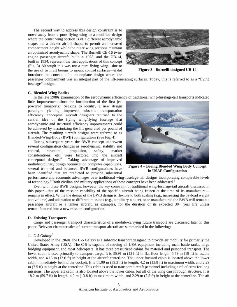
A key design constraint for flying wing transports is the vertical height of the required internal cargo or passenger compartment. As the Fig. 2 photograph of the B-2 shows, even with a respectful span of 172 ft, a substantial fuselage bulge was required to provide suitable volume for the cockpit and bomb bay for a flying wing designed to cruise at high subsonic speeds for intercontinental distances.
One way to address this design constraint is to make the aircraft sufficiently large that the thickness of the wing can accommodate a reasonable cargo or passenger compartment height. However, with respect to reasonable-sized airliners, Nickel and Wohlfahrt, circa 1990, conclude: “It seems to be impossible with current technology to design a commercially viable all-wing airliner where the passengers and freight are almost completely integrated in the wing.”2
Figure 1 - Fairchild XC-120 with detachable module
Figure 2 - B-2 flying wing
American Institute of Aeronautics and Astronautics
3
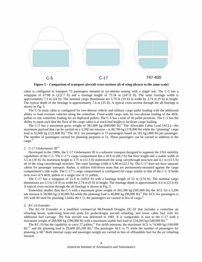
Figure 3 - Burnelli-designed UB-14
Figure 4 – Boeing Blended Wing Body Conceptin USAF Configuration
The second way to address this design constraint is to move away from a pure flying wing to a modified design where the center wing section is of a different aerodynamic shape, i.e. a thicker airfoil shape, to permit an increased compartment height while the outer wing sections maintain an optimized aerodynamic shape. The Burnelli CB-16 twin-engine passenger aircraft, built in 1928, and the UB-14, built in 1934, represent the first applications of this concept (Fig. 3) Although this was not a pure flying wing—due to the use of twin aft booms to mount control surfaces—it did introduce the concept of a monoplane design where the passenger compartment was an integral part of the lift-generating surfaces. Today, this is referred to as a “flying fuselage” design.
C. Blended Wing Bodies In the late 1980s examination of the aerodynamic efficiency of traditional wing-fuselage-tail transports indicated
little improvement since the introduction of the first jet-powered transports.3 Seeking to identify a new design paradigm yielding improved subsonic transportation efficiency, conceptual aircraft designers returned to the central idea of the flying wing/flying fuselage that aerodynamic and structural efficiency improvements could be achieved by maximizing the lift generated per pound of aircraft. The resulting aircraft designs were referred to as Blended-Wing-Body (BWB) configurations (See Fig. 4).
During subsequent years the BWB concept underwent several configuration changes as aerodynamic, stability and control, structural, propulsion, safety, market considerations, etc. were factored into the aircraft conceptual designs.4 Taking advantage of improved multidisciplinary design optimization computer capabilities, several trimmed and balanced BWB configurations have been identified that are predicted to provide substantial performance and economic advantages over traditional wing-fuselage-tail designs incorporating comparable levels of technology.5 Both civilian and military applications of these concepts have been addressed.6
Even with these BWB designs, however, the key constraint of traditional wing-fuselage-tail aircraft discussed in this paper—that of the mission capability of the specific aircraft being frozen at the time of its manufacture—remains in effect. While the design of the BWB design is flexible to both scaling (e.g., increasing the payload weight and volume) and adaptation to different missions (e.g., a military tanker), once manufactured the BWB will remain a passenger aircraft or a tanker aircraft, as examples, for the duration of its expected 30+ year life unless remanufactured into a new mission configuration.
D. Existing Transports Cargo and passenger transport characteristics of a module-carrying future transport are discussed later in this
paper. Relevant characteristics of current transport aircraft are summarized in the following:
1. C-5 Galaxy7 Developed in the 1960s, the C-5 Galaxy is a subsonic transport designed to provide air mobility for primarily the
United States Army (USA). The C-5 is capable of moving all USA equipment including main battle tanks, large bridging equipment, and most helicopters. It has three pressurized cabins for materiel and personnel transport. The lower cabin is used primarily to transport cargo. It is 36.91 m (121 ft) in flat floor length, 5.79 m (19 ft) in usable width, and 4.15 m (13.6 ft) in height at the aircraft centerline. The upper forward cabin is located above the lower cabin immediately behind the cockpit. It is 11.99 m (39.3 ft) in length, 4.2 m (13.8 ft) in maximum width, and 2.29 m (7.5 ft) in height at the centerline. This cabin is used to transport aircraft personnel including a relief crew for long missions. The upper aft cabin is also located above the lower cabin, but aft of the wing carrythrough structure. It is 18.2 m (59.7 ft) in length, 4.2 m (13.8 ft) in maximum width, and 2.29 m (7.5 ft) in height at the centerline. The aft
American Institute of Aeronautics and Astronautics
4
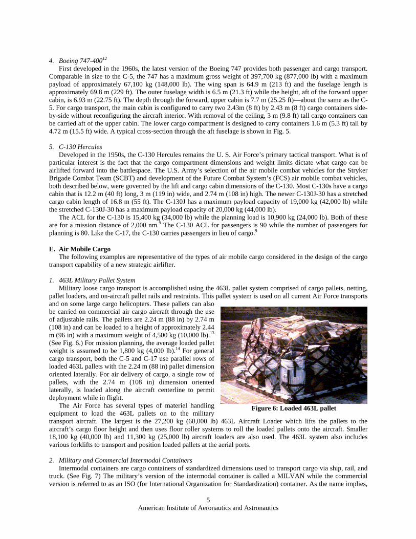
cabin is configured to transport 75 passengers situated in six-abreast seating with a single isle. The C-5 has a wingspan of 67.88 m (222.7 ft) and a fuselage length of 75.54 m (247.8 ft). The outer fuselage width is approximately 7.3 m (24 ft). The nominal cargo dimensions are 5.79 m (19 ft) in width by 2.74 m (9 ft) in height. The typical depth of the fuselage is approximately 7.6 m (25 ft). A typical cross-section through the aft fuselage is shown in Fig. 5.
The C-5s main cabin is configured for two-abreast vehicle and military cargo pallet loading with the additional ability to load oversize vehicles along the centerline. Fixed-width cargo rails for two-abreast loading of the 463L pallets or one centerline loading for air deployed pallets. The C-5 has a total of 36 pallet positions. The C-5 has the ability to squat such that the floor of the cargo cabin is at truck-bed height to facilitate cargo loading.
The C-5 has a maximum gross weight of 381,000 kg (840,000 lb).8 The Allowable Cabin Load (ACL)—the maximum payload that can be carried on a 3,200 nm mission—is 80,700 kg (178,000 lb) while the “planning” cargo load is 55,600 kg (122,600 lb).9 The ACL for passengers is 73 passengers based on 181 kg (400 lb) per passenger. The number of passengers carried for planning purposes is 51. These passengers can be carried in addition to the cargo.9
2. C-17 Globemaster III10
Developed in the 1980s, the C-17 Globemaster III is a subsonic transport designed to augment the USA mobility capabilities of the C-5. The C-17’s cargo compartment has a 20.8 m (68.2 ft) flat floor length and a usable width of 5.5 m (18 ft). Its maximum height is 3.75 m (12.3 ft) underneath the wing carrythrough structure and 4.1 m (13.5 ft) aft of the wing carrythrough structure. The outer fuselage width is 6.86 m (22.5 ft). The C-17 does not have separate cabins for passenger transport. Rather, it utilizes fold-down seats that are permanently-mounted against the cargo compartment’s side walls. The C-17’s cargo compartment is configured for cargo similar to that of the C-5. It holds twin rows of 9 463L pallets or a single row of 11 pallets.
The C-17 has a wingspan of 51.8 m (169.8 ft) with a fuselage length of 53 m (174 ft). The nominal cargo dimensions are 5.5 m (18 ft) in width by 2.74 m (9 ft) in height. The fuselage depth is approximately 6.6 m (21.6 ft). A typical cross-section through the aft fuselage is shown in Fig. 5.
Somewhat smaller than the C-5 with a maximum gross weight of 265,300 kg (585,000 lb), the ACL for a 3,200 nm mission is 58,960 kg (130,000 lb) while the planning load is 40,800 kg (90,000 lb).9 The ACL for passengers is 101 with 90 used for planning. Unlike the C-5, the passengers are carried in lieu of cargo.9
3. KC-10 Extender
The KC-10 Extender is a modified commercial McDonnell Douglas DC-10 that includes a centerline air refueling boom, underwing hose-reel pods for probe/drogue aircraft refueling, and lower cabin fuel cells for additional fuel carriage. The first aircraft was delivered in 1981. It is comparable in size to the C-17 with a maximum weight of 268,900 kg (590,000 lb) with a maximum usable fuel load of 154,200 kg (340,000 lb).11
The KC-10 has the capability to carry 27 pallets.11 For airlift missions, the maximum ACL is 74,400 kg (164,000 lb) 11 and the planning load is 29,600 (65,200 lb).9 The passenger ACL is 75 while the number of passengers for planning is 68.9 Both internal cargo and passenger weight are carried in lieu of offloadable fuel for the air refueling mission.
C-5 C-17 747-400
Figure 5 – Comparison of transport aircraft cross-sections aft of wing (drawn to the same scale)
American Institute of Aeronautics and Astronautics
5
4. Boeing 747-40012
First developed in the 1960s, the latest version of the Boeing 747 provides both passenger and cargo transport. Comparable in size to the C-5, the 747 has a maximum gross weight of 397,700 kg (877,000 lb) with a maximum payload of approximately 67,100 kg (148,000 lb). The wing span is 64.9 m (213 ft) and the fuselage length is approximately 69.8 m (229 ft). The outer fuselage width is 6.5 m (21.3 ft) while the height, aft of the forward upper cabin, is 6.93 m (22.75 ft). The depth through the forward, upper cabin is 7.7 m (25.25 ft)—about the same as the C-5. For cargo transport, the main cabin is configured to carry two 2.43m (8 ft) by 2.43 m (8 ft) cargo containers side-by-side without reconfiguring the aircraft interior. With removal of the ceiling, 3 m (9.8 ft) tall cargo containers can be carried aft of the upper cabin. The lower cargo compartment is designed to carry containers 1.6 m (5.3 ft) tall by 4.72 m (15.5 ft) wide. A typical cross-section through the aft fuselage is shown in Fig. 5.
5. C-130 Hercules
Developed in the 1950s, the C-130 Hercules remains the U. S. Air Force’s primary tactical transport. What is of particular interest is the fact that the cargo compartment dimensions and weight limits dictate what cargo can be airlifted forward into the battlespace. The U.S. Army’s selection of the air mobile combat vehicles for the Stryker Brigade Combat Team (SCBT) and development of the Future Combat System’s (FCS) air mobile combat vehicles, both described below, were governed by the lift and cargo cabin dimensions of the C-130. Most C-130s have a cargo cabin that is 12.2 m (40 ft) long, 3 m (119 in) wide, and 2.74 m (108 in) high. The newer C-130J-30 has a stretched cargo cabin length of 16.8 m (55 ft). The C-130J has a maximum payload capacity of 19,000 kg (42,000 lb) while the stretched C-130J-30 has a maximum payload capacity of 20,000 kg (44,000 lb).
The ACL for the C-130 is 15,400 kg (34,000 lb) while the planning load is 10,900 kg (24,000 lb). Both of these are for a mission distance of 2,000 nm.9 The C-130 ACL for passengers is 90 while the number of passengers for planning is 80. Like the C-17, the C-130 carries passengers in lieu of cargo.9
E. Air Mobile Cargo The following examples are representative of the types of air mobile cargo considered in the design of the cargo
transport capability of a new strategic airlifter.
1. 463L Military Pallet System Military loose cargo transport is accomplished using the 463L pallet system comprised of cargo pallets, netting,
pallet loaders, and on-aircraft pallet rails and restraints. This pallet system is used on all current Air Force transports and on some large cargo helicopters. These pallets can also be carried on commercial air cargo aircraft through the use of adjustable rails. The pallets are 2.24 m (88 in) by 2.74 m (108 in) and can be loaded to a height of approximately 2.44 m (96 in) with a maximum weight of 4,500 kg (10,000 lb).13 (See Fig. 6.) For mission planning, the average loaded pallet weight is assumed to be 1,800 kg (4,000 lb).14 For general cargo transport, both the C-5 and C-17 use parallel rows of loaded 463L pallets with the 2.24 m (88 in) pallet dimension oriented laterally. For air delivery of cargo, a single row of pallets, with the 2.74 m (108 in) dimension oriented laterally, is loaded along the aircraft centerline to permit deployment while in flight.
The Air Force has several types of materiel handling equipment to load the 463L pallets on to the military transport aircraft. The largest is the 27,200 kg (60,000 lb) 463L Aircraft Loader which lifts the pallets to the aircraft’s cargo floor height and then uses floor roller systems to roll the loaded pallets onto the aircraft. Smaller 18,100 kg (40,000 lb) and 11,300 kg (25,000 lb) aircraft loaders are also used. The 463L system also includes various forklifts to transport and position loaded pallets at the aerial ports.
2. Military and Commercial Intermodal Containers
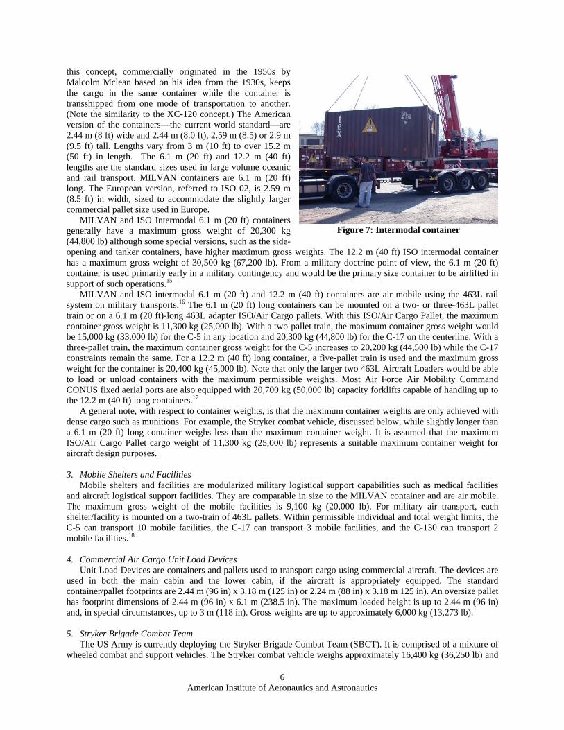
Intermodal containers are cargo containers of standardized dimensions used to transport cargo via ship, rail, and truck. (See Fig. 7) The military’s version of the intermodal container is called a MILVAN while the commercial version is referred to as an ISO (for International Organization for Standardization) container. As the name implies,
Figure 6: Loaded 463L pallet
American Institute of Aeronautics and Astronautics
6
Figure 7: Intermodal container
this concept, commercially originated in the 1950s by Malcolm Mclean based on his idea from the 1930s, keeps the cargo in the same container while the container is transshipped from one mode of transportation to another. (Note the similarity to the XC-120 concept.) The American version of the containers—the current world standard—are 2.44 m (8 ft) wide and 2.44 m (8.0 ft), 2.59 m (8.5) or 2.9 m (9.5 ft) tall. Lengths vary from 3 m (10 ft) to over 15.2 m (50 ft) in length. The 6.1 m (20 ft) and 12.2 m (40 ft) lengths are the standard sizes used in large volume oceanic and rail transport. MILVAN containers are 6.1 m (20 ft) long. The European version, referred to ISO 02, is 2.59 m (8.5 ft) in width, sized to accommodate the slightly larger commercial pallet size used in Europe.
MILVAN and ISO Intermodal 6.1 m (20 ft) containers generally have a maximum gross weight of 20,300 kg (44,800 lb) although some special versions, such as the side-opening and tanker containers, have higher maximum gross weights. The 12.2 m (40 ft) ISO intermodal container has a maximum gross weight of 30,500 kg (67,200 lb). From a military doctrine point of view, the 6.1 m (20 ft) container is used primarily early in a military contingency and would be the primary size container to be airlifted in support of such operations.15
MILVAN and ISO intermodal 6.1 m (20 ft) and 12.2 m (40 ft) containers are air mobile using the 463L rail system on military transports.16 The 6.1 m (20 ft) long containers can be mounted on a two- or three-463L pallet train or on a 6.1 m (20 ft)-long 463L adapter ISO/Air Cargo pallets. With this ISO/Air Cargo Pallet, the maximum container gross weight is 11,300 kg (25,000 lb). With a two-pallet train, the maximum container gross weight would be 15,000 kg (33,000 lb) for the C-5 in any location and 20,300 kg (44,800 lb) for the C-17 on the centerline. With a three-pallet train, the maximum container gross weight for the C-5 increases to 20,200 kg (44,500 lb) while the C-17 constraints remain the same. For a 12.2 m (40 ft) long container, a five-pallet train is used and the maximum gross weight for the container is 20,400 kg (45,000 lb). Note that only the larger two 463L Aircraft Loaders would be able to load or unload containers with the maximum permissible weights. Most Air Force Air Mobility Command CONUS fixed aerial ports are also equipped with 20,700 kg (50,000 lb) capacity forklifts capable of handling up to the 12.2 m (40 ft) long containers.17
A general note, with respect to container weights, is that the maximum container weights are only achieved with dense cargo such as munitions. For example, the Stryker combat vehicle, discussed below, while slightly longer than a 6.1 m (20 ft) long container weighs less than the maximum container weight. It is assumed that the maximum ISO/Air Cargo Pallet cargo weight of 11,300 kg (25,000 lb) represents a suitable maximum container weight for aircraft design purposes.
3. Mobile Shelters and Facilities
Mobile shelters and facilities are modularized military logistical support capabilities such as medical facilities and aircraft logistical support facilities. They are comparable in size to the MILVAN container and are air mobile. The maximum gross weight of the mobile facilities is 9,100 kg (20,000 lb). For military air transport, each shelter/facility is mounted on a two-train of 463L pallets. Within permissible individual and total weight limits, the C-5 can transport 10 mobile facilities, the C-17 can transport 3 mobile facilities, and the C-130 can transport 2 mobile facilities.18
4. Commercial Air Cargo Unit Load Devices
Unit Load Devices are containers and pallets used to transport cargo using commercial aircraft. The devices are used in both the main cabin and the lower cabin, if the aircraft is appropriately equipped. The standard container/pallet footprints are 2.44 m (96 in) x 3.18 m (125 in) or 2.24 m (88 in) x 3.18 m 125 in). An oversize pallet has footprint dimensions of 2.44 m (96 in) x 6.1 m (238.5 in). The maximum loaded height is up to 2.44 m (96 in) and, in special circumstances, up to 3 m (118 in). Gross weights are up to approximately 6,000 kg (13,273 lb).
5. Stryker Brigade Combat Team
The US Army is currently deploying the Stryker Brigade Combat Team (SBCT). It is comprised of a mixture of wheeled combat and support vehicles. The Stryker combat vehicle weighs approximately 16,400 kg (36,250 lb) and

American Institute of Aeronautics and Astronautics
7
Figure 8: Stryker combat vehicle being unloaded
from a military cargo aircraft
is 7 m (275 in) long, 2.72 m (107 in) wide, and 2.64 m (104 in) tall (See Fig. 8). The possible need for improved armor to protect against new threats holds open the possibility that the weight of the Stryker combat vehicle may grow to approximately 19,500 kg (43,000 lb).* The largest non-combat vehicle is the Heavy Expanded Mobility Tactical Truck (HEMTT). Of the different HMETT configurations, the largest is 10.85m (427 in) long, 2.44 m (96 in) wide, and 2.57 m (101 in) tall. These trucks have an empty curb weight of approximately 17,200 kg (38,000 lb) without any additional armor protection.
The SBCT encompasses approximately 14,000 tons and 3,500 personnel.† Three days of sustainment, not including fuel and water, adds an additional 2,500 tons. The air mobility support group required to receive the embarking equipment and personnel at the Forward Operating Location (FOL) requires 900 tons of equipment and approximately 1,000 personnel.19
6. Future Combat System
The future U.S. Army air mobile fighting force is called the Future Combat System (FCS). It may take the place of the Stryker combat vehicle. Because of the constraints on tactical air mobility, the current emphasis is on a family of FCS vehicles comparable in physical size to the Stryker so that tactical air transport via the C-130 is possible. For the purpose of this paper, consistent with a general design philosophy of providing performance margin for future growth, the maximum FCS weight is assumed to be 22,700 kg (50,000 lb).‡
7. Personnel transport
The aisle height in passenger compartments in commercial transports is typically 1.93 m (76 in) or greater. Long distance seat accommodations, designed to enable passenger rest during long transoceanic flights, are up to 0.64 m (25 in) in width and have a seat pitch of up to 2.1 m (83 in) to permit the seat to recline into a flat bed. Typical aisle widths are 0.56 m (22 in) with an aisle located next to every seat, except for the outboard seats, to provide for the minimal disturbance of sleeping passengers.
III. Future Air Force Mobility Aircraft Capability Needs Lessons-learned from recent United States military operations have reemphasized the importance of air mobility
capabilities and heightened senior-level interest in identifying and resolving possible gaps in meeting anticipated future air mobility needs. Two air mobility areas pertinent to the discussion of the conceptual design of a future military transport aircraft are air refueling and force deployment and sustainment, and initial response and persistent airpower operations. Each of these areas is discussed in the following.
A. Air Refueling Developed initially during the 1950s as a critical element of United States nuclear deterrent capabilities, tankers
provide a core air mobility capability enabling global access for United States and allied military air forces. The United States Air Force provides the bulk of these tanker resources through its 530 KC-135 Stratotanker and 59 KC-10 Extender aircraft.
1. Current Air Force Tanker Performance
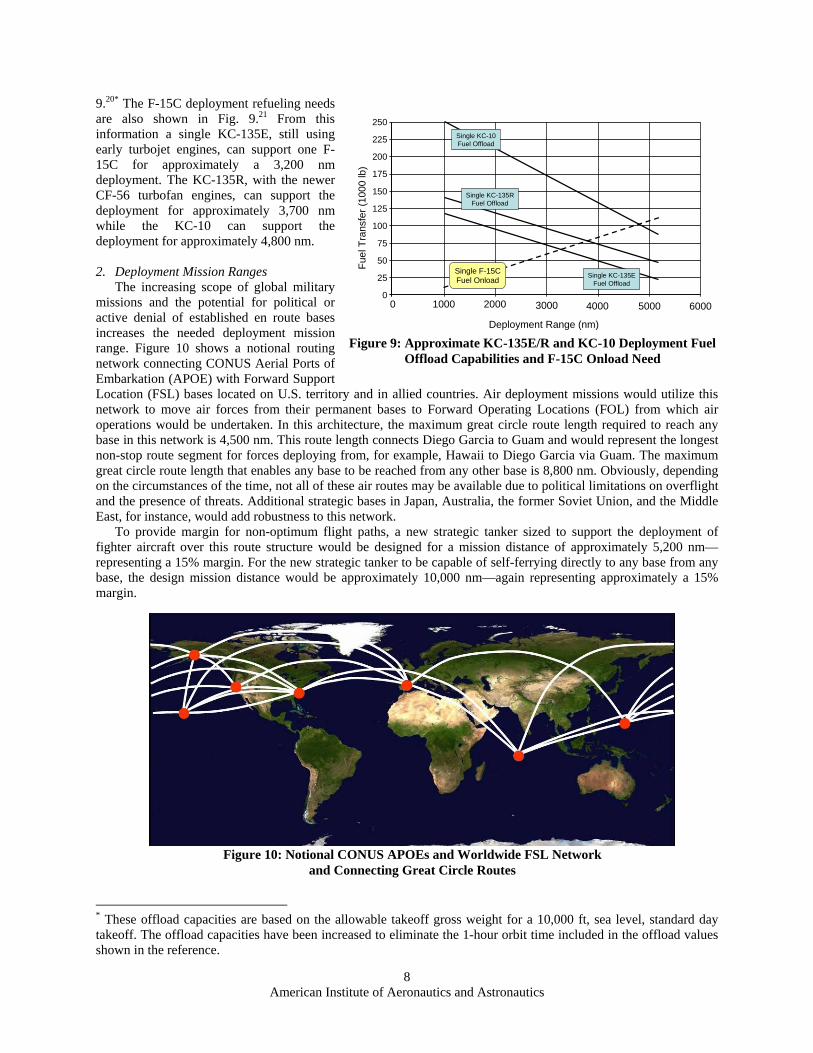
The primary Air Force tanker missions are to escort and provide en route refueling to other aircraft during deployments and to refuel combat aircraft, such as fighters, during operational missions. Approximate values for the unrestricted takeoff weight offload capacities vs. deployment range of the KC-135E/R and KC-10 are shown in Fig.
* This increase of approximately 3,200 kg (7,000 lb) is taken from page 28 of the Ref. 19. † The 14,000 tons includes 1,225 tons of added armor weight as noted on page 28 of the Ref. 19. ‡ Recall that the new C-130J and C-130J-30 have a maximum payload of 19,000 kg (42,000lb) and 20,000 kg (44,000 lb), respectively.
American Institute of Aeronautics and Astronautics
8
0
25
50
75
100
125
150
175
200
0 1000 2000 3000 4000
Deployment Range (nm)
Fuel
Tra
nsfe
r (10
00 lb
)
5000 6000
225
250Single KC-10Fuel Offload
Single KC-135RFuel Offload
Single KC-135EFuel Offload
Single F-15CFuel Onload
Figure 9: Approximate KC-135E/R and KC-10 Deployment Fuel Offload Capabilities and F-15C Onload Need
9.20* The F-15C deployment refueling needs are also shown in Fig. 9.21 From this information a single KC-135E, still using early turbojet engines, can support one F-15C for approximately a 3,200 nm deployment. The KC-135R, with the newer CF-56 turbofan engines, can support the deployment for approximately 3,700 nm while the KC-10 can support the deployment for approximately 4,800 nm.
2. Deployment Mission Ranges
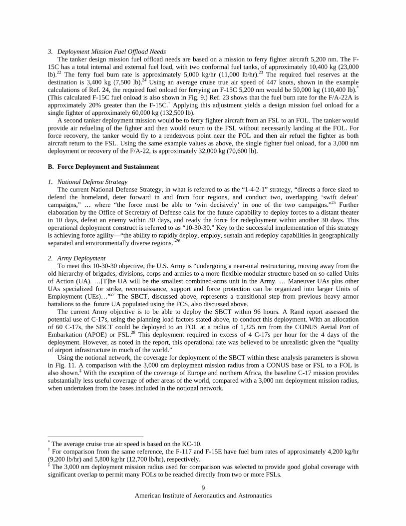
The increasing scope of global military missions and the potential for political or active denial of established en route bases increases the needed deployment mission range. Figure 10 shows a notional routing network connecting CONUS Aerial Ports of Embarkation (APOE) with Forward Support Location (FSL) bases located on U.S. territory and in allied countries. Air deployment missions would utilize this network to move air forces from their permanent bases to Forward Operating Locations (FOL) from which air operations would be undertaken. In this architecture, the maximum great circle route length required to reach any base in this network is 4,500 nm. This route length connects Diego Garcia to Guam and would represent the longest non-stop route segment for forces deploying from, for example, Hawaii to Diego Garcia via Guam. The maximum great circle route length that enables any base to be reached from any other base is 8,800 nm. Obviously, depending on the circumstances of the time, not all of these air routes may be available due to political limitations on overflight and the presence of threats. Additional strategic bases in Japan, Australia, the former Soviet Union, and the Middle East, for instance, would add robustness to this network.
To provide margin for non-optimum flight paths, a new strategic tanker sized to support the deployment of fighter aircraft over this route structure would be designed for a mission distance of approximately 5,200 nm—representing a 15% margin. For the new strategic tanker to be capable of self-ferrying directly to any base from any base, the design mission distance would be approximately 10,000 nm—again representing approximately a 15% margin.
* These offload capacities are based on the allowable takeoff gross weight for a 10,000 ft, sea level, standard day takeoff. The offload capacities have been increased to eliminate the 1-hour orbit time included in the offload values shown in the reference.
Figure 10: Notional CONUS APOEs and Worldwide FSL Network and Connecting Great Circle Routes
American Institute of Aeronautics and Astronautics
9
3. Deployment Mission Fuel Offload Needs The tanker design mission fuel offload needs are based on a mission to ferry fighter aircraft 5,200 nm. The F-
15C has a total internal and external fuel load, with two conformal fuel tanks, of approximately 10,400 kg (23,000 lb).22 The ferry fuel burn rate is approximately 5,000 kg/hr (11,000 lb/hr).23 The required fuel reserves at the destination is 3,400 kg (7,500 lb).24 Using an average cruise true air speed of 447 knots, shown in the example calculations of Ref. 24, the required fuel onload for ferrying an F-15C 5,200 nm would be 50,000 kg (110,400 lb).* (This calculated F-15C fuel onload is also shown in Fig. 9.) Ref. 23 shows that the fuel burn rate for the F/A-22A is approximately 20% greater than the F-15C.† Applying this adjustment yields a design mission fuel onload for a single fighter of approximately 60,000 kg (132,500 lb).
A second tanker deployment mission would be to ferry fighter aircraft from an FSL to an FOL. The tanker would provide air refueling of the fighter and then would return to the FSL without necessarily landing at the FOL. For force recovery, the tanker would fly to a rendezvous point near the FOL and then air refuel the fighter as both aircraft return to the FSL. Using the same example values as above, the single fighter fuel onload, for a 3,000 nm deployment or recovery of the F/A-22, is approximately 32,000 kg (70,600 lb).
B. Force Deployment and Sustainment
1. National Defense Strategy The current National Defense Strategy, in what is referred to as the “1-4-2-1” strategy, “directs a force sized to
defend the homeland, deter forward in and from four regions, and conduct two, overlapping ‘swift defeat’ campaigns,” … where “the force must be able to ‘win decisively’ in one of the two campaigns.”25 Further elaboration by the Office of Secretary of Defense calls for the future capability to deploy forces to a distant theater in 10 days, defeat an enemy within 30 days, and ready the force for redeployment within another 30 days. This operational deployment construct is referred to as “10-30-30.” Key to the successful implementation of this strategy is achieving force agility—“the ability to rapidly deploy, employ, sustain and redeploy capabilities in geographically separated and environmentally diverse regions.”26
2. Army Deployment
To meet this 10-30-30 objective, the U.S. Army is “undergoing a near-total restructuring, moving away from the old hierarchy of brigades, divisions, corps and armies to a more flexible modular structure based on so called Units of Action (UA). …[T]he UA will be the smallest combined-arms unit in the Army. … Maneuver UAs plus other UAs specialized for strike, reconnaissance, support and force protection can be organized into larger Units of Employment (UEs)…”27 The SBCT, discussed above, represents a transitional step from previous heavy armor battalions to the future UA populated using the FCS, also discussed above.
The current Army objective is to be able to deploy the SBCT within 96 hours. A Rand report assessed the potential use of C-17s, using the planning load factors stated above, to conduct this deployment. With an allocation of 60 C-17s, the SBCT could be deployed to an FOL at a radius of 1,325 nm from the CONUS Aerial Port of Embarkation (APOE) or FSL.28 This deployment required in excess of 4 C-17s per hour for the 4 days of the deployment. However, as noted in the report, this operational rate was believed to be unrealistic given the “quality of airport infrastructure in much of the world.”
Using the notional network, the coverage for deployment of the SBCT within these analysis parameters is shown in Fig. 11. A comparison with the 3,000 nm deployment mission radius from a CONUS base or FSL to a FOL is also shown.‡ With the exception of the coverage of Europe and northern Africa, the baseline C-17 mission provides substantially less useful coverage of other areas of the world, compared with a 3,000 nm deployment mission radius, when undertaken from the bases included in the notional network.
* The average cruise true air speed is based on the KC-10. † For comparison from the same reference, the F-117 and F-15E have fuel burn rates of approximately 4,200 kg/hr (9,200 lb/hr) and 5,800 kg/hr (12,700 lb/hr), respectively. ‡ The 3,000 nm deployment mission radius used for comparison was selected to provide good global coverage with significant overlap to permit many FOLs to be reached directly from two or more FSLs.

American Institute of Aeronautics and Astronautics
10
3. Air Forces Deployment
The Air Force now operates under the Air Expeditionary Force (AEF) construct emphasizing mobile and rapidly deployable air and space forces. In organizing, deploying, and sustaining these forces, the military’s “unit-type code” (UTC) is used to “bin” warfighting materiel and personnel. Deployed AEFs are comprised of selected UTCs integrated together to provide a specific mission capability from a specified operating location. A UTC may range from as few as two people with minimal materiel to upwards of hundreds of personnel with hundreds of tons of materiel. Recently, a wing vice commander stated “We are no longer a wing-based Air Force; we no longer live in a wing-based world. We are now a UTC-based Air Force; we now live in a UTC-based world.”29
Air mobile deployment of AEFs involve ferrying aircraft and transporting containerized and palletized cargo, mobile facilities and shelters, wheeled vehicles, fuel, water, and passengers. For the projection of air and space power, the Air Force objective is to globally deploy and initiate operations for the first AEF within 48 hours and five AEFs within 15 days.
C. Persistent Air Power Operations For many years during the Cold War with the Soviet Union, U.S. strategic nuclear air forces maintained
persistent armed air operations to ensure an ability to respond rapidly to a surprise nuclear attack on the United States. This operational concept was expensive, using the aeronautical technologies of the 1950s and 1960s, and was discontinued as confidence in land- and sea-based ballistic missiles and remote intelligence gathering improved.
With a suitably design aircraft—range, payload flexibility, crew accommodations, and sufficient on-board consumables such as food, water, and oil—new transport aircraft would be able to remain flying for many days. The famous Voyager round-the-world aircraft record of the 1990s showed both the capability to remain flying for many days and to cover large geographic distances. In the 1930s, the world record for air-refueled flight was established at 29 days and involved over 450 air refuelings and resupply. This was done in a single-engine aircraft and a two-person crew.
Applying the persistence of sea force projection to air power is a new military construct. From Fig. 11, using the CONUS and FSL bases shown in the notional network, each 3,000 nm radius represents an area of responsibility. Airborne battle groups, consisting of large subsonic transports configured with air refueling, command and control, intelligence, and power projection capabilities, would fly multiday missions within their area of responsibility. Patrol patterns within the area of responsibility would constantly shift to enhance survivability, increase uncertainty in potential adversaries, and enable air power to be effectively combined with sea power to provide an integrated military power projection capability. The airborne aircraft would be refueled with tankers operating from the bases in the network. As needed, the air power capabilities of the airborne aircraft would be augmented through the use of tactical aircraft operating from these same bases. For example, the F/A-22 would use its efficient supersonic cruise capability to takeoff and rapidly join up with the airborne battle team to enhance air superiority, provide defense against airborne and surface threats, and provide additional power projection capabilities.
Figure 11: 1,325 nm and 3,000 nm mission radii from the FSLs in the notional network
American Institute of Aeronautics and Astronautics
11
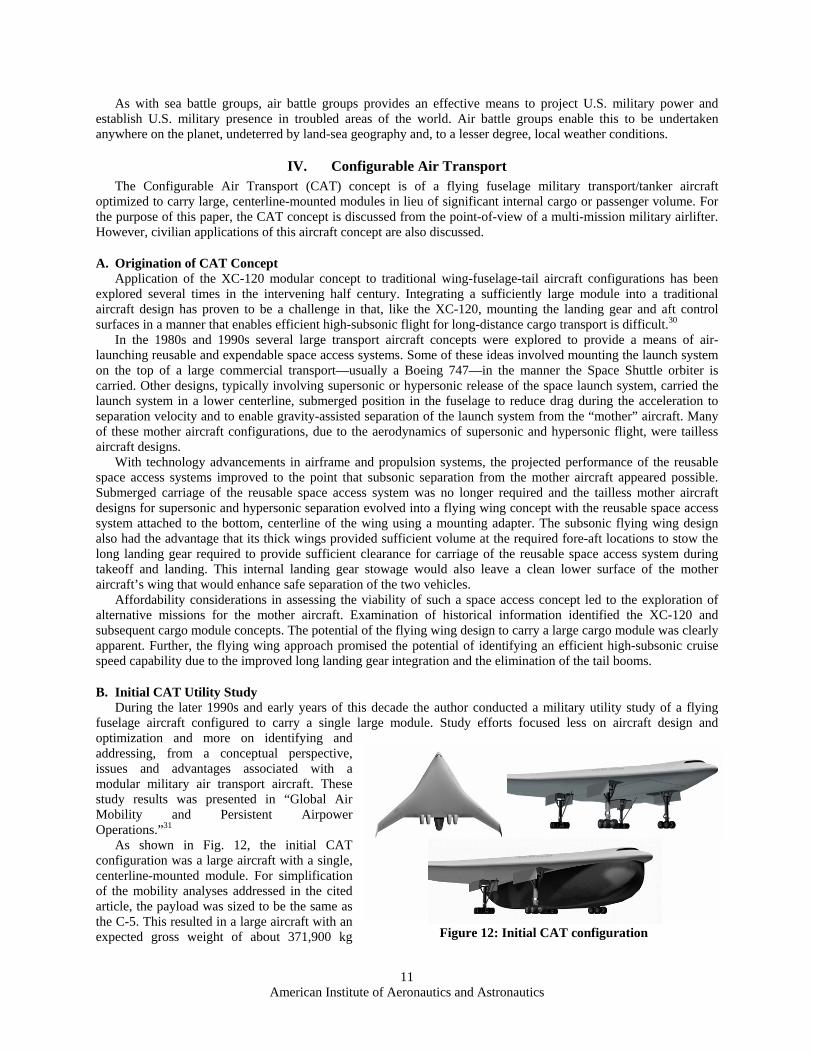
Figure 12: Initial CAT configuration
As with sea battle groups, air battle groups provides an effective means to project U.S. military power and establish U.S. military presence in troubled areas of the world. Air battle groups enable this to be undertaken anywhere on the planet, undeterred by land-sea geography and, to a lesser degree, local weather conditions.
IV. Configurable Air Transport The Configurable Air Transport (CAT) concept is of a flying fuselage military transport/tanker aircraft
optimized to carry large, centerline-mounted modules in lieu of significant internal cargo or passenger volume. For the purpose of this paper, the CAT concept is discussed from the point-of-view of a multi-mission military airlifter. However, civilian applications of this aircraft concept are also discussed.
A. Origination of CAT Concept Application of the XC-120 modular concept to traditional wing-fuselage-tail aircraft configurations has been
explored several times in the intervening half century. Integrating a sufficiently large module into a traditional aircraft design has proven to be a challenge in that, like the XC-120, mounting the landing gear and aft control surfaces in a manner that enables efficient high-subsonic flight for long-distance cargo transport is difficult.30
In the 1980s and 1990s several large transport aircraft concepts were explored to provide a means of air-launching reusable and expendable space access systems. Some of these ideas involved mounting the launch system on the top of a large commercial transport—usually a Boeing 747—in the manner the Space Shuttle orbiter is carried. Other designs, typically involving supersonic or hypersonic release of the space launch system, carried the launch system in a lower centerline, submerged position in the fuselage to reduce drag during the acceleration to separation velocity and to enable gravity-assisted separation of the launch system from the “mother” aircraft. Many of these mother aircraft configurations, due to the aerodynamics of supersonic and hypersonic flight, were tailless aircraft designs.
With technology advancements in airframe and propulsion systems, the projected performance of the reusable space access systems improved to the point that subsonic separation from the mother aircraft appeared possible. Submerged carriage of the reusable space access system was no longer required and the tailless mother aircraft designs for supersonic and hypersonic separation evolved into a flying wing concept with the reusable space access system attached to the bottom, centerline of the wing using a mounting adapter. The subsonic flying wing design also had the advantage that its thick wings provided sufficient volume at the required fore-aft locations to stow the long landing gear required to provide sufficient clearance for carriage of the reusable space access system during takeoff and landing. This internal landing gear stowage would also leave a clean lower surface of the mother aircraft’s wing that would enhance safe separation of the two vehicles.
Affordability considerations in assessing the viability of such a space access concept led to the exploration of alternative missions for the mother aircraft. Examination of historical information identified the XC-120 and subsequent cargo module concepts. The potential of the flying wing design to carry a large cargo module was clearly apparent. Further, the flying wing approach promised the potential of identifying an efficient high-subsonic cruise speed capability due to the improved long landing gear integration and the elimination of the tail booms.
B. Initial CAT Utility Study During the later 1990s and early years of this decade the author conducted a military utility study of a flying
fuselage aircraft configured to carry a single large module. Study efforts focused less on aircraft design and optimization and more on identifying and addressing, from a conceptual perspective, issues and advantages associated with a modular military air transport aircraft. These study results was presented in “Global Air Mobility and Persistent Airpower Operations.”31
As shown in Fig. 12, the initial CAT configuration was a large aircraft with a single, centerline-mounted module. For simplification of the mobility analyses addressed in the cited article, the payload was sized to be the same as the C-5. This resulted in a large aircraft with an expected gross weight of about 371,900 kg

American Institute of Aeronautics and Astronautics
12
(820,000 lb), a wing span of approximately 85.3 m (280 ft), and an unrefueled global range of approximately 8,000 nm. The module was approximately 45.7 m (150 ft) in length, 9.1 m (30 ft) in width, and 5.8 m (19 ft) in height. These values were not based on specific conceptual design analysis of the CAT, but were based on published BWB aircraft size, range, and payload conceptual design information. This reflected an early emphasis on addressing the question of the potential military utility of a modular air transport. As discussed in Ref. 31, there appears to be significant military utility for a modular air transport not only for deploying military forces but also for providing a global range air platform for conducting persistent airpower missions.
C. Updated CAT
1. Design Needs Using the previously discussed cargo transport and military mission needs, the Table 1 parameters are used to
update the conceptual design of the CAT. Note that these parameters do no address oversize and extra heavy cargo such as the Abrams M-1A1 main battle tank. The fleet of C-5 and C-17 aircraft is expected be able to meet these air transport needs for the foreseeable future as well as provide unique mission capabilities such as paratroop airdrop.
Design Need Value Rationale CAT tanker deployment range between APOEs and FSLs
5,200 nm Enables CAT tanker to escort deploying AEF aircraft to any FSL without en route basing
CAT tanker deployment mission radius from FSL to/from FOL
3,000 nm Enables CAT tanker to escort AEF aircraft to and from FOLs without en route bases
CAT tanker offload capacity during deployment escort mission between APOEs and FSLs
60,000 kg (132,500 lb)
Enables single CAT to escort single F/A-22-equivalent aircraft to any FSL without en route stops outside the network
CAT tanker max fuel balanced field length
8,000 ft Consistent with NATO airfields
CAT refueling capabilities Wing-mounted refueling booms and probe/drogue to provide
redundant/two-aircraft-at-a-time refueling points
Enhances global deployment by minimizing number of tankers
CAT unrefueled cargo transport with aircraft cargo load
5,200 nm Defined by the notional FSL network with a 15 % margin
CAT unrefueled deployment range without module
10,000 nm Enables CATs to be globally repositioned without en route base support to support rapid AEF deployments
CAT transport maximum payload balanced field length
10,000 ft Consistent with runway lengths of major Air Force bases
Internal military passenger transport
181 kg (400 lb) each with personal baggage and combat gear
Provides ability within the CAT to carry combat-ready passengers
Aircraft crew member 104 kg (230 lb) each with personal baggage
SBCT/FCS transport All SBCT/FCS components up to 22,700 kg (50,000 lb)
Enables global deployment of SBCT elements
Typical SBCT single vehicle envelope
7 m (275 in) long x 2.7 m (107 in) wide x 2.64 m (104 in) tall
Standard SBCT vehicle
Maximum SBCT single vehicle envelope
10.8 m (427 in) long x 2.44 m (96 in) wide x 2.57 m (101 in) tall
Largest SBCT vehicle
463L pallets 1,800 kg (4,000 lb) average; 4,500 kg (10,000 lb) maximum pallet
weight
Enables use of Air Force standardized pallets
Military shelters and facilities 9,100 kg (20,000 lb) max Enables transport of deployment facilities
Table 1: Updated CAT Design Parameters

American Institute of Aeronautics and Astronautics
13
Figure 13: Updated CAT cargo module cross-section (right) compared with C-5 (left)
7 - 463L Pallets7 - 463L Pallets
SBCT VehicleSBCT Vehicle
Military Facility Military FacilityMilitary Facility Military Facility
6 - Commercial 96” x 125” Pallets6 - Commercial 96” x 125” Pallets
16.8 m (55 ft)
Figure 14: Updated CAT cargo module flat floor layout
MILVAN/ISO Intermodal container 2.6 m (102 in) wide x 2.6 m (102 in
tall x 6.1 m (20 ft) long; 12,100 kg (26,700 lb) average with ISO/air
cargo pallet
Enables transport of typical military-used containers
Commercial air cargo container 2.24 m (88in)/2.24 m (96 in) x 2.44 m (96 in) tall x 3.18 m (125 in) @
6,000 kg (13,273 lb) max
Enables transport of commercial containers for interoperability
Module maximum payload weight 24,200 kg (53,400 lb) Two ISO containers and associated ISO/air cargo pallets
Module average payload weight 12,700 kg (28,000 lb) Seven 463L pallets with average loads
CAT average planning load 42,200 kg (93,000 lb) Three sets of average loaded 463L pallets plus 19 military passengers and 6 crew members
2. Updated Module Configuration
The original CAT configuration envisioned a large cargo module with approximately the same internal volume, flat cabin floor area, and payload capabilities as the C-5. This was primarily done to permit comparisons of the CAT and C-5 in terms of cargo throughput for deployment missions. In this paper, an alternative module configuration will be explored. From Table 1, the design payload cross-section, which encompasses the identified cargo, is 3.18 m (125 in) wide by 2.74 m (108 in) tall. A module cross-section built around this design payload cross-section, and compared to the C-5, is shown in Fig. 13. The shaded box in the right cross-section represents the composite payload envelope. This updated CAT module is approximately 3.76 m (12.3 ft) tall and 4.27 m (13.9 ft) wide. The inside CAT module cabin height is 2.84 m (112 in) to provide a modest increase over the 2.74 m (108 in) height of the C-130.
The updated cargo module’s flat floor is 3.33 m (131 in) wide by 16.8 m (55 ft) long—the same length as the new C-130J-30. As shown in Fig. 14, this provides for the carriage of:
(a) Seven 463L pallets with an average total weight of 12,700 kg (28,000 lb);
(b) The maximum SBCT vehicle length with the maximum FCS vehicle weight of 22,700 kg (50,000 lb);
(c) Two 6.1 m (20 ft) military facilities or ISO containers with a maximum weight of 24,200 kg (53,400 lb; including two ISO/air cargo pallets); and
(d) Six commercial 2.44 m (96 in) pallets with an average pallet weight of 4,000 kg (8,900 lb) or seven commercial 2.24 m (88 in) pallets with an average pallet weight of 3,500 kg (7,600 kg).
A perspective view of the updated CAT cargo module is shown in Fig. 15. This conceptual design uses a forward fairing and an extended tail cone encompassing a traditional folding ramp. The overall module is approximately 30.5m (100 ft) long, 3.8 m (12.4 ft) tall, and 4.3 m (14 ft) wide without the wheel fairings. The cargo bay is 2.8 m (112 in) tall and 3.3 m (131 in) wide. Comparable measurements for the C-130 are 2.7 m (107 in) tall and 2.8 m 109 in) wide. (Note that illustration in Fig. 15 represents simply a sketch of the module and does not reflect any structural or aerodynamic optimization analyses.)

American Institute of Aeronautics and Astronautics
14
Figure 15: Updated CAT module
The assumed empty weight of the cargo module is 11,300 kg (25,000 lb) based on a comparison with the fuselage/hull weight of the C-130H.* The maximum loaded weight of the module would be approximately 35,600 kg (78,400 lb) when carrying two ISO containers. The average loaded weight of a module carrying 463L pallets would be 24,000 kg (53,000 lb).
For passenger transport, the module would be configured with five 463L pallets configured with 48 seats, one 463L pallet with two containers for passenger baggage, and one 463L pallet configured with a galley and rest rooms. Using an assumed weight of 113 kg (250 lb) per passenger, the total passenger weight would be 5,400 kg (12,000 lb).† Passenger accommodations (e.g., seats, galley, and passenger consumables) would add approximately 5,900 kg (13,000 lb) for a total payload weight of approximately 11,300 kg (25,000 lb).
The XC-120 demonstration, as seen in Fig. 1, showed that light-weight, mountable wheels were suitable for moving the approximately 11,300 kg (25,000 lb) module using a standard aircraft tow cart.‡ A similar approach using internally-stowed wheels could be used for the larger 35,600 kg (78,400 lb) CAT module. These wheels would be electrically-powered, directionally-controllable, and electro-hydraulically raised and lowered. For separation of the module from the aircraft, the wheels would be lowered until in contact with the ground. The module-to-aircraft clamps would be released and the wheels would lower the module until sufficient height clearance between the module and aircraft is achieved. For short distance movement of the module on the ground—to clear the ramp area where the CATs are loaded and unloaded—the electrically-powered wheels, powered by an internal auxiliary power unit (APU) would be used. For movement of the module on the airport, an aircraft tow cart or a commercial truck cab would be used. For road or rail movement, the module would be elevated to enable it to be positioned above a “low-boy” trailer where the module’s self-contained wheels would lower the module into position on the trailer.
For module loading and unloading, the module would be backed up to a standard loading dock. The module’s wheels would be used to position the module at the height of the loading dock and level it relative to the loading dock. Cargo pallets, mobile facilities, ISO containers, and wheeled vehicles can then be easily and rapidly loaded and unloaded. If a suitable loading dock is not available, the wheels can position the module at the appropriate height for use of the aft cargo ramp, offloading to flatbed trucks, or using special purpose cargo handling equipment.
An unusual scheme for enhanced module ground mobility is to use an air cushion system employing a self-inflating skirt assembly built into the bottom of the module. The air cushion would be powered by a self-contained, 500 HP APU that would also provide power for the module’s wheels, ramp and cargo door, environmental control, and internal power. This air cushion system would enable the module to be maneuvered off hard-surface ramps onto grass or graded earth for storage. It would also enable modules to traverse ground with modest tire ruts, ditches, or similar obstacles that would otherwise prove difficult to traverse with the module wheels.
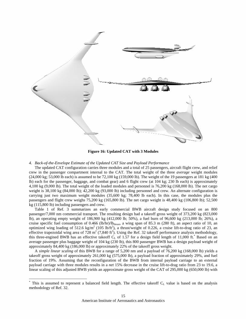
3. Updated CAT Configuration
The updated CAT configuration, shown in Fig. 16, adopts a flying fuselage configuration following Burnelli’s idea of embedding the cockpit and passenger compartment within the wing. This results in a flying fuselage design with a wing centerbody, sized to accommodate the cockpit and a modest passenger compartment that also incorporates a broad lower surface suitable for carrying three CAT cargo modules. This provides a basic CAT aircraft with the clean configuration of a pure flying fuselage with high cruise L/D ratio, high fuel fraction, and a long unrefueled range for rapid global movement of the aircraft. It also enables this same aircraft to be rapidly and easily mission configured through the addition of underwing-mounted cargo or mission modules. * Recall that the standard C-130H has a flat floor length of 12.2 m (40 ft) and the updated CAT module has a flat floor length of 16.8 m (55 ft). Also, the CAT module is slightly wider and taller. For these reasons, the 11,300 kg (25,000 lb) CAT module empty weight used in this conceptual design is approximately 60 percent greater than the empty weight of the C-130H fuselage/hull. † The combat passenger weight is assumed to be 113 kg (250 lb) to provide an increased passenger baggage weight of 9 kg (20 lb) compared with the normal passenger and baggage weight of 104 kg (230 lb). ‡ Based on the 8,200 kg (18,000 lb) maximum payload weight of the XC-120 and an assumed module weight of 3,200kg (7,000 lb).
American Institute of Aeronautics and Astronautics
15
4. Back-of-the-Envelope Estimate of the Updated CAT Size and Payload Performance
The updated CAT configuration carries three modules and a total of 25 passengers, aircraft flight crew, and relief crew in the passenger compartment internal to the CAT. The total weight of the three average weight modules (24,000 kg; 53,000 lb each) is assumed to be 72,100 kg (159,000 lb). The weight of the 19 passengers at 181 kg (400 lb) each for the passenger, baggage, and combat gear) and 6 flight crew (at 104 kg; 230 lb each) is approximately 4,100 kg (9,000 lb). The total weight of the loaded modules and personnel is 76,200 kg (168,000 lb). The net cargo weight is 38,100 kg (84,000 lb); 42,200 kg (93,000 lb) including personnel and crew. An alternate configuration is carrying just two maximum weight modules (35,600 kg; 78,400 lb each). In this case, the modules plus the passengers and flight crew weighs 75,200 kg (165,800 lb). The net cargo weight is 48,400 kg (106,800 lb); 52,500 kg (115,800 lb) including passengers and crew.
Table 1 of Ref. 3 summarizes an early commercial BWB aircraft design study focused on an 800 passenger/7,000 nm commercial transport. The resulting design had a takeoff gross weight of 373,200 kg (823,000 lb), an operating empty weight of 186,900 kg (412,000 lb; 50%), a fuel burn of 96,600 kg (213,000 lb; 26%), a cruise specific fuel consumption of 0.466 (lb/hr)/lbthrust, a wing span of 85.3 m (280 ft), an aspect ratio of 10, an optimized wing loading of 512.6 kg/m2 (105 lb/ft2), a thrust/weight of 0.226, a cruise lift-to-drag ratio of 23, an effective trapezoidal wing area of 728 m2 (7,840 ft2). Using the Ref. 32 takeoff performance analysis methodology, this three-engined BWB has an effective takeoff CL of 1.57 for a design field length of 11,000 ft.* Based on an average passenger plus baggage weight of 104 kg (230 lb), this 800 passenger BWB has a design payload weight of approximately 84,400 kg (186,000 lb) or approximately 22% of the takeoff gross weight.
A simple linear scaling of this BWB for a range of 5,200 nm and a payload of 76,200 kg (168,000 lb) yields a takeoff gross weight of approximately 261,000 kg (575,000 lb), a payload fraction of approximately 29%, and fuel fraction of 19%. Assuming that the reconfiguration of the BWB from internal payload carriage to an external payload carriage with three modules results in a net 15% decrease in the cruise lift-to-drag ratio from 23 to 19.6, a linear scaling of this adjusted BWB yields an approximate gross weight of the CAT of 295,000 kg (650,000 lb) with
* This is assumed to represent a balanced field length. The effective takeoff CL value is based on the analysis methodology of Ref. 32.
Figure 16: Updated CAT with 3 Modules
American Institute of Aeronautics and Astronautics
16
a fuel burn of 66,700 kg (147,000 lb) (22,000 gal., 23%). The 76,200 kg (168,000 lb) payload is 26% of the takeoff gross weight. The updated CAT’s scaled effective trapezoidal wing area would be approximately 576 m2 (6,200 ft2). Retaining the aspect ratio of 10 yields a wing span of approximately 76 m (249 ft).*
As noted in Table 1 above, at the maximum gross weight the CAT should be capable of taking off at sea level with a balanced field length of 10,000 ft. Applying the Ref. 32 takeoff performance methodology for a CAT with four engines and a net 10% reduction in the BWB’s effective takeoff CL, the required field length can be achieved with an engine thrust-to-weight ratio of 0.26.† For the tanker mission, the CAT should be able to takeoff in a sea level balanced field length of 8,000 ft. The tanker mission payload weight would be 60,800 kg (134,000 lb), including 60,100 kg (132,500 lb) in fuel offload and 680 kg (1,500 lb) for the crew. The tanker takeoff gross weight would be 280,000 kg (617,000 lb). Applying the Ref. 32 methodology shows that the clean CAT would be able to achieve the desired balanced field length of 8,000 ft with an effective takeoff CL of 1.55—comparable to the value calculated for the referenced BWB.
In these back-of-the-envelope CAT sizing calculations, the original BWB empty weight fraction of 50 percent was not changed. Recall that the BWB carries the entire payload internally. With an assumed average combined payload density of about 7 lb/ft3 for passengers and baggage, the adjusted BWB with 168,000 lb of payload has approximately 680 m3 (24,000 ft3) of interior, pressurized compartments—equivalent to a 279 m2 (3,000 ft2) home—inside the thick centerbody (see Fig. 4). The CAT, on the other hand, has a slender centerbody with a more modest internal pressurized compartment. The structural weight associated with the carriage of the payload, rather than being included in the aircraft empty weight as with the BWB, is included in the module empty weights accounted for as part of the total payload weight. Hence, maintaining the 50 percent empty weight fraction is assumed to provide sufficient margin for growth in engine weights due to the increased thrust-to-weight ratio, the increase in the number of engines, the longer landing gear, the module–to-wing structural adapters, and the air refueling pods.
5. Module Carriage
As shown in Fig. 16, the updated CAT carries up to three modules attached to the module adapters mounted on the lower wing surface. The module adapters contain the clamps for restraining the modules, provide power, environmental control, communications, and other interfaces between the aircraft and the module, and provide for the distribution of the module loads into the wing primary structure. The module adapters also include a hatch providing access from the module to a lateral pressurized walkway within the wing that interconnects the modules with the passenger compartment in the wing centerbody.
The modules are spaced laterally with approximately a 3 m (10 ft) gap to minimize interference drag at high subsonic cruise velocities. Longitudinally, the modules are located towards the aft end of wing centerbody such that the loaded module center of gravity aligns within the aircraft’s center of gravity envelope. This enables any combination of module locations to be used without exceeding the aircraft’s longitudinal center of gravity limits.
Vertically, the modules are located such that the bottom of the module is approximately .76 m (30 in) from the ground. This locates the floor of the module at approximately 1.22 m (48 in) from the ground and permits direct unloading of the module onto flatbed trucks while the module remains attached to the aircraft.
6. Module Mating/Demating
The late 1940’s film of the unloading of a module from the XC-120—from which the photographs in Fig. 1 were taken—shows that the process of attaching and detaching the module is fairly simple. On the XC-120, electric winches on the aircraft were used to raise and lower the module once the mating latches were released. The overall process of manually installing the four sets of wheels, attaching the four straps, lowering the module, detaching the straps, attaching a tow bar and connecting the tow truck appeared to take about 10-15 minutes.
With the use of electrically-deployed and controlled wheels and latches, the time required to release and lower a module may be as short of five minutes. Hence, for a one-way transfer of cargo modules, the total time that the CAT would be on the ground—land, taxi, sequentially detach three modules, taxi, and takeoff—might amount to only 30 minutes and be accomplished without shutting down the engines. For comparison, the C-17’s ground time for expedited unloading without refueling or reconfiguration is 95 minutes.33
A preliminary time allocation for a typical CAT module delivery and pickup at a CONUS APOE base or FSL is approximately 150 minutes: 10 minutes for taxiing following landing, 15 minutes to sequentially demate the three * The CAT conceptual design retains the wingtips shown in most BWB conceptual designs to provide an increased effective aspect ratio and improved cruise L/D. † An assumed net 10% reduction in the effective CL reflects a cleaner CAT configuration, compared with the BWB, but also includes the effect of the increased drag due to the three modules.

American Institute of Aeronautics and Astronautics
17
modules, 60 minutes to taxi and refuel the CAT, 20 minutes to taxi and position the CAT and modules for mating, 15 minutes to sequentially mate the modules, 20 minutes for anomaly resolution and final checks, and 10 minutes to taxi to the runway for takeoff.* Without refueling, the total ground time to drop modules and pickup modules would be approximately 90 minutes. The C-17, for comparison, requires nearly 400 minutes of planning ground time for unloading cargo, refueling, reconfiguring the cargo compartment, and loading cargo.34 For only unloading and refueling the aircraft, the C-17’s planning ground time is 195 minutes.
D. Simple Army Combat Brigade Delivery Mission Analysis The potential benefits of using the modular CAT, compared with the C-17, for transporting Army air-mobile
combat brigade can be identified through the use of first-order analysis of base cargo throughput.
1. Mission Assumptions The air mobility mission modeled is to transport the combat brigade from its permanent base through an
intermediate FSL to a FOL. At the FOL, the combat brigade vehicles, equipment, and personnel would be transferred to C-130s or equivalent tactical airlifters already positioned at the FOL.
The global reach element of this mission assumes a mission range of 5,200 nm—the longest network leg distance. An adequate fuel supply, supported by a permanent fueling hydrant system, is assumed at the departing and FSL bases. Adequate aircraft and module parking locations at both bases is also assumed. A stockpile of war-ready modules is assumed to be available to support the combat brigade deployment.
The regional reach element of this mission assumes a mission radius of 3,000 nm from the nearest FSL in the network to the FOLs. Adequate fuel supplies and parking locations are assumed at the departing FSL. No fuel is assumed to be available at the FOL to support regional airlift—all available fuel and fueling equipment are assumed to be prioritized to support the tactical airlift of the combat brigade.
In this simulation the Army air mobile brigade, as discussed earlier, is comprised of 14,000 tons of vehicles and equipment, 3,500 personnel, and 2,500 tons of initial sustainment for three days of operation. The supporting Air Force contingent is 900 tons and 1,000 personnel. The total deployment, assumed to a single FOL, is 17,400 tons and 4,500 personnel.
2. CAT Mission Capability
For the global reach element, the CAT is assumed to be capable of transporting three modules over a distance of 5,200 nm without requiring air refueling. For the regional reach element, the CAT is assumed to be capable of delivering three modules from the FSL to the APOE and then returning to the FSL with three empty modules without refueling at the APOE or air refueling.
Each module is assumed to carry seven 463L pallets loaded to an average weight of 1,800 kg (4,000 lb). The average module payload is 12,700 kg (28,000 lb) or 14 tons. The total payload, for three average-loaded modules, is 38,100 kg (84,000 lb) or 42 tons. The total payload for two maximum weight modules would be 47,200 kg (104,000 lb) or 52 tons. For this mission module, three average-loaded modules are used. No credit for passenger transport in the upper deck is assumed.
For passenger transport, as described above, each passenger-configured CAT module carries 48 passengers. At an assumed combat passenger and baggage weight of 113 kg (250 lb) each, the total passenger weight is 5,400 kg (12,000 lb) or 6 tons. The 4,500 personnel to be transported have a total weight of 510,200 kg (1,125,000 lb) or 562.5 tons. To account in the simulation for the lower loaded weight of the passenger-figured module vs. a cargo module, the weight of the passengers must be increased by the ratio of the average-loaded payload to the passenger payload weight. This ratio is 14 tons / 6 tons = 2.33. The adjusted passenger weight is approximately 1,300 tons. With this adjustment in passenger payload weight, the combat brigade deployment, and supporting Air Force personnel, constitutes the movement of 17,400 + 1,300 = 18,700 tons.
3. C-17 Mission Capability
The C-17 carries 18 463L pallets for a total average load of 32,600 kg (72,000 lb) or 36 tons. However, the average planning load for the C-17 is 40,800 kg (90,000 lb) or 45 tons.35 This higher value will be used in the analysis.
For passenger transport, the C-17 also has the ability to transport 144 passengers using a combination of palletized seats and the normal cargo cabin sidewall seats. At 250 lb each, the total passenger weight is 16,300 kg * This timeline assumes a hydrant system for refueling with two hookups to the aircraft, each with an average flow rate of 450 gallons per minute. Onloading 22,000 gallons of fuel would require approximately 30 minutes.

American Institute of Aeronautics and Astronautics
18
(36,000 lb) or 18 tons. To account in the simulation for the lower total weight of passengers, the weight of the passengers must be increased by the ratio of the average planning load to the passenger payload weight or 45 tons / 18 tons = 2.5. The adjusted passenger weight is approximately 1,400 tons. With this adjustment in passenger payload weight, the combat brigade deployment constitutes the movement of 17,400 + 1,400 = 18,800 tons.
For both the strategic and regional airlift missions, the C-17 will require air refueling. For this analysis, it is assumed that the necessary tankers are available to support the C-17 missions. For the regional airlift mission, the C-17 is assumed to be refueled at the FOL.
4. FOL Throughput Estimation
Using the analysis methodology of Ref. 36, the payload throughput at the FOL can be estimated. For this analysis, the FOL is assumed to operate 24 hours per day with a queuing efficiency of 85 percent. The aircraft-specific inputs are the C-17 and CAT payload, of 45 tons and 42 tons, respectively, and average aircraft ground time of 3.25 hours and 1.5 hours, respectively. The independent variable is the number of aircraft parking locations (referred to as the maximum on ground or MOG).
The throughput calculation is:
Max Throughput = MOG A/C Payload Airport Operating Hours Queuing Eff. ÷ A/C Ground Time Using the C-17 and CAT payloads and ground times described above, the maximum FOL throughput is shown
in Fig. 17. This comparison assumes that the C-17 is not reloaded with cargo or reconfigured. However, the C-17 is refueled. The CAT is not refueled at the FOL as it has sufficient performance to return to the FSL without air refueling. The CAT does, however, load returning modules. From this simple analysis, the CAT provides approximately a 100 percent increase in throughput.
The same analysis yields an estimate of the number of aircraft per day landing at the FOL. This estimate is shown in Fig. 18. As expected, it also shows that the CAT provides approximately a 100 percent increase in the number of aircraft being unloaded each day or enables a reduction by approximately one half of the number of parking locations required at the FOL.
The effective tonnage required to be transported for the Stryker Combat Brigade Team, as discussed above, is 18,700 tons and 18,800 tons for the CAT and C-17, respectively. The number of days required to complete delivery of the total tonnage, as a function of the maximum number of aircraft parking locations, is shown in Fig. 19. The dependent variable (vertical) axis scale has been set to a maximum of 10 days consistent with the emerging national military strategy to delivery the initial ground forces within 10 days. In reviewing the analysis results shown in Fig. 19, note that the time required to delivery of the brigade to the FOL must be augmented by the time required to airlift the brigade from its permanent or temporary base to the FSL, the time to move the brigade forward using tactical transports or land transport, and the time required to prepare the brigade for combat. Hence, the total time permitted to delivery the tonnage at the FOL may be of the order of 4-6 days, not the total 10 days.
0
1,000
2,000
3,000
4,000
5,000
6,000
1 2 3 4 5 6 7 8 9 10
MOG
Tons
/ D
ay
CATC-17
Figure 17: C-17 and CAT Maximum FOL Throughput (tons/day) as a Function of the Maximum Number of Aircraft Parking Locations (MOG)

American Institute of Aeronautics and Astronautics
19
E. Application to Airborne Missions
The primary advantage of the CAT concept is that a common strategic transport aircraft can be used for a variety of airborne missions through the use of missionized modules. The C-130-size cargo modules can be used for this purpose or, if needed, super modules, as shown as a generic shape in Fig. 20, can be used. Such a super module may be up to 26 m (85 ft) in length, 18.3 m (60 ft) in width, and 4 m (13 ft) in height and have an internal flat floor area of approximately 280 m2 (3,000 ft2). The super module’s gross weight may be up to 72,600 kg (160,000 lb) without exceeding the CAT takeoff gross weight limits. Partially fueling the CAT for takeoff and then air refueling would enable the gross weight of the super module to increase further. Examples of the use of a super module would be a new integrated command, control, and intelligence center or a flying hospital complete with operating and intensive care facilities. In both of these examples, the mission can be carried out either in the air or while the module is parked at an FSL or FOL. An expeditionary hospital facility at a FOL, as shown in Fig. 21, would use a super module for the surgical and diagnostic facilities and use regular modules for patient care facilities, medical personnel rest quarters, on-site power generation, supplies warehousing, and similar applications. The patient care facilities would be capable of both providing care while on the ground or while returning critical patients to CONUS for continued medical care.
Not only does the CAT provide broad mission flexibility by carrying a wide range of different missionized modules, it also provides an affordable path for modernizing existing airborne missions as current aircraft (e.g., AWACS) reach the end of their economic life. Rather than starting a new aircraft procurement in each instance—
0
20
40
60
80
100
120
140
160
1 2 3 4 5 6 7 8 9 10
MOG
Airc
raft
Unl
oadi
ngs
per D
ay CATC-17
Figure 18: FOL Aircraft Unloadings per Day
0
1
2
3
4
5
6
7
8
9
10
1 2 3 4 5 6 7 8 9 10
MOG
Day
s to
Com
plet
eBr
igad
e D
eliv
ery
C-17CAT
Figure 19: Days to Complete Brigade Delivery – Vehicles, Palletized and Containerized Cargo, Personnel, and Initial Combat Sustainment

American Institute of Aeronautics and Astronautics
20
usually resulting in an entirely different airframe with different performance, training, basing, and logistics support needs—the CAT approach enables new mission modules to be quickly developed and deployed. This approach takes advantage of the expected 50-year life of a new large transport fleet to reduce future operating costs through minimization of transport aircraft types in service while enabling mission capabilities to be easily updated.
V. Extensions to Other Mission Areas
A. Modular Solutions to Other Military Needs The Department of Defense is experiencing a broad need for new and improved air mobility not seen since the
1950s and 1960s. In addition to the apparent need for global air mobility and air refueling capabilities, there is interest in a new fixed-wing, short takeoff or landing (STOL) tactical transport to support the air mobility of the Army’s FCS. There is also Army interest in a light-than-air vehicle for supporting forward force deployment and sustainment and there is a joint Army and Marine Corps interest in a heavy helicopter that can also support FCS transport and sustainment.
Figure 20: CAT with Super Module
Power generation
Rest quarters
Supplies
Water, O2, etc.
Patient carefacilities
Ambulancedrop-off
point
Surgical &diagnostics
Figure 21: Notional FOL hospital facility

American Institute of Aeronautics and Astronautics
21
All of these needs share the common payload weight and envelope generally defined by the Army’s FCS. This commonality offers the possibility that the standard cargo module developed for the CAT could become the standard cargo module used by these other three vehicles. This new air transportation architecture would have the ability to pick up a loaded module at the manufacturer’s location in CONUS or the military depot and rapidly deliver the module directly to the warfighter anywhere in the world. The en route need to unload and reload cargo, vehicles, and personnel from one aircraft to another would be eliminated resulting in significant reductions in needed support personnel and equipment and throughput deliver time.
B. Commercial Air Freighter Uses Boeing Company’s 2004 forecast for freighter aircraft anticipates a worldwide demand for nearly 3,000 new air
freighter aircraft by 2023.37 Assuming an average aircraft cost of $200M ($FY05), the potential sales approaches $600B ($FY05). Module-transporting aircraft could capture a significant share of this future market.
Commercial aircraft, like all other commercial transport systems, generate revenue only when moving. As seen with the comparison of the CAT and C-17, the modular construct enables fewer aircraft to provide the same throughput. For commercial aircraft, this could result in increased return on investment and provide possible operating advantages to airfreight companies operating such module-transporting aircraft. It is possible that a large strategic transport aircraft family providing value to both military and commercial users could develop using a common module much as the military now uses the intermodal container. It is further possible that the integration of regional fixed-wing, heavy helicopter and lighter-than-air modes of transport, discussed above, would enable the airfreight company to provide global door-to-door pickup and delivery of user-owned modules. This would provide a paradigm shift in air cargo capabilities; potentially further stimulating growth in global air cargo delivery.
C. Commercial Passenger Transport The market for under 175-passenger aircraft, during the next 20 years, will approach 17,000 aircraft.38 A CAT
carrying three passenger modules will carry approximately 150 passengers. Introduction of modularity into the passenger market provides several interesting advantages discussed briefly in the following:
1. Airport Design
The combination of the passenger module and the ease of detaching and attaching the module to the aircraft enable the current mode of airport ramp operation of having the passenger aircraft unload passengers at the terminal to be replaced by a system where the module is detached from the aircraft and moved to the terminal. The aircraft proceeds to refueling and crew rotation, and then on to picking up another module. The aircraft is not dedicated to a particular route, but picks up the next module ready for departure. The aircraft does not approach the terminal permitting the terminal to be more compact in size.
As shown in Fig. 22, the arriving module enters the terminal—now configured like a train station—where, at the first stop, the passengers disembark; at the second stop the baggage and cargo are unloaded directly into the baggage carousels; at the third stop the module is cleaned and restocked for the next use; at the fourth stop, departing
Arriving passengersdisembark
Baggage loading equip.Departing passengers seating
Baggage unloaded to carousel
Module restocking
Module cleaning Restrooms
Door
Arriving passengersdisembark
Baggage loading equip.Departing passengers seating
Baggage unloaded to carousel
Module restocking
Module cleaning Restrooms
RampGate 1
Gate 2
Door
Ramp
Figure 22: Notional Airport Gate Design for Passenger Modules
American Institute of Aeronautics and Astronautics
22
passengers embark; and at the final stop the cargo and passenger baggage is loaded. At this point the module departs the terminal and moves, under its own power, to the location on the ramp where the aircraft will pick it up. Note that all module operations are inside providing enhanced passenger comfort and minimizing outside support operations that usually slow ground turn around times and create operating delays. Walking distance in the terminal from the passenger drop-off point to the module loading area should also be reduced.
These changes may result in improved utilization of the aircraft and return on investment. They may also enable more efficient passenger movement through the airport, a smaller airport terminal footprint, and a smaller required investment in funds and purchased land to build new airports. It is possible that urban airports, incorporating passenger modules and STOL regional transports, can be tucked into downtown areas not normally considered as potential airport sites. At the existing hub airports, this approach may enable greater passenger throughput without increasing the size of the terminal.
2. In-Flight Security
In-flight security remains an important terrorist denial issue. The passenger modules provide additional separation of the flight crew from the passenger compartment both during flight and for access to the aircraft while it is on the ground. While this may not prevent hostilities directed at the passengers, it would prevent the aircraft from being taken over and used as weapons against ground targets.
3. Passenger and Cargo Mixed Operations
The interoperability of passenger and cargo modules enables various mixes of passenger and cargo modules to be adjusted for the hour of the day, day of the week, and season of the year. Passenger modules may be carried during the day and cargo modules at night. During mid-week, when passenger service is usually less in demand, more cargo modules can be carried. During seasonal demands for passenger travel, e.g., during the holidays, additional passenger modules can be carried to increase seat availability. With the ability to carry both passenger or cargo modules, the distinction between “passenger” and freighter” aircraft would go away yielding opportunities for increased revenue generation compared to dedicated conventional aircraft. This, combined with the increased aircraft utilization rate, may yield significant operating advantages.*
D. Sky Yachts Private ocean yachts provide the means for wealthy people to own sea-mobile quarters that can be moved from
place to place. While it may appear at first to be frivolous, privately-owned modules configured as “sky yachts” could be moved via the same module-carrying aircraft. This would enable individuals to take personal quarters to locations not accessible by sea.
The sky yacht also provides an alternative to owning or leasing a jet aircraft for corporate use. With a growing global economy, this provides corporate executives with air-mobile offices and quarters that would, to a degree, minimize the burden of frequent and extended business travel. Rather than moving from hotel to hotel, they would temporarily “dock” their sky yacht at the airport’s “marina,” conduct meetings in secure offices in the module, sleep in their cabins, and depart when business is concluded. They would also be capable of conducting business meetings or resting in the private quarters during the flight as the sky yacht is moved to the next location.
VI. Conclusion Fairchild’s innovative idea for a modular air transport has been updated by combining it with the equally
innovative Burnelli flying fuselage aircraft design approach to yield a strategic military transport that provides extensive mission flexibility with the global range necessary to rapidly deploy, project, and sustain U.S. military power. The focus of this paper was to update the author’s previous idea for such a Configurable Air Transport or CAT with a refined configuration better suited to the particular future air transport needs of the U.S. Army’s air-mobile Future Combat System. The refined approach—still, however, very much just a “sketch” of an idea—retains the advantages of using an easily and rapidly changeable module while reducing the size of the module to enable cross-platform utilization with fixed-wing, STOL tactical transports, lighter-than-air craft, and heavy helicopters.
* It is also possible that specialized cargo modules would be developed for carrying fresh fish, flowers, other food items, horses, race cars, etc. —all examples of specialized air cargo delivery missions. This would further increase the operating advantage of a modular aircraft since the aircraft would not need to undergo specialized reconfiguration to transport such cargo.
American Institute of Aeronautics and Astronautics
23
Just as containerized cargo using standardized intermodal shipping containers has revolutionized terrestrial surface transportation and brought about significant reductions in transportation cost and speed, standardization of a cross-platform air module could achieve similar improvements in military and commercial air mobility. At a minimum, it provides the Air Force with an interesting concept to be further explored as new air strategic and tactical air mobility and air power projection capabilities are explored.
Acknowledgements
The author acknowledges the contribution of John Livingston, Dave Hammond and Dale Kristof, all of the U.S. Air Force Aeronautical Systems Center at Wright-Patterson Air Force Base, for their assistance in developing and refining the CAT concept. The author also acknowledges the conceptual depictions of the original CAT configuration developed by Dennis Stewart and Isiah Davenport, General Dynamics, Advanced Information Systems. Finally, the author wishes to recognize the fundamental ideas originated at Fairchild Corp. and by Vincent Burnelli that may now bear fruit.
References
1 Nickel, K., and Wohlfahrt, M., Tailless Aircraft in Theory and Practice, AIAA, Inc., Washington, DC, 1994, pp. 2. 2 Nickel, K., and Wohlfahrt, M., Tailless Aircraft in Theory and Practice, AIAA, Inc., Washington, DC, 1994, pp. 19. 3 Liebeck, R.H., Page, M.A., and Rawdon, B.K., “Blended-Wing-Body Subsonic Commercial Transport,” AIAA 1998-
16309, pp. 2. 4 Kiebeck, R., “Design of the Blended-Wing-Body Subsonic Transport,” AIAA 2002-0002. 5 Roman, D., Gilmore, R., and Wakayama, S., “Aerodynamics of High-Subsonic Blended-Sing-Body Configurations,” AIAA
2003-554. 6 Liebeck, R.H., “Blended Wing-body Design Challenges,” AIAA 2003-2659. 7 “C-5 Handbook,” USAF Air Mobility Warfare Center Logistics Division, June 1995. 8 Air Mobility Planning Factors, Air Force Pamphlet 10-1403, 18 Dec 2003, Table 2, pp.11. 9 Air Mobility Planning Factors, Air Force Pamphlet 10-1403, 18 Dec 2003, Table 3, pp.12. 10 “C-17: First Look Aircraft Systems Handbook,” USAF Air Mobility Warfare Center Logistics Division, May 1995. 11 Air Mobility Command Data Book, May 2004. 12 “747-400 Airplane Characteristics for Airport Planning,” Boeing Commercial Airplanes, Airplane Description, Section 2,
December 2002. 13 “Joint Tactics, Techniques, and Procedures for the Use of Intermodal Containers in Joint Operations,” United States
Department of Defense, Joint Publication 4-10-7, January 8, 1997, pp. II-41. 14 “Joint Tactics, Techniques, and Procedures for the Use of Intermodal Containers in Joint Operations,” United States
Department of Defense, Joint Publication 4-10-7, January 8, 1997, pp. V-9. 15 “Joint Tactics, Techniques, and Procedures for the Use of Intermodal Containers in Joint Operations,” United States
Department of Defense, Joint Publication 4-10-7, January 8, 1997, pp. II-22. 16 “Joint Tactics, Techniques, and Procedures for the Use of Intermodal Containers in Joint Operations,” United States
Department of Defense, Joint Publication 4-10-7, January 8, 1997, Chapter III, Section C. Air Transportation, pp. III-10-12. 17 “Joint Tactics, Techniques, and Procedures for the Use of Intermodal Containers in Joint Operations,” United States
Department of Defense, Joint Publication 4-10-7, January 8, 1997, pp. V-9. 18 “Joint Tactics, Techniques, and Procedures for the Use of Intermodal Containers in Joint Operations,” United States
Department of Defense, Joint Publication 4-10-7, January 8, 1997, pp. II-38. 19 A. Vick, D. Orletsky, et. al., “The Stryker Brigade Combat Team: Rethinking Strategic Responsiveness and Assessing
Deployment Options,” Rand Report MR1606, pp. 17. 20 Air Mobility Planning Factors, Air Force Pamphlet 10-1403, 18 Dec 2003, Table 10, pp.17. 21 Air Mobility Planning Factors, Air Force Pamphlet 10-1403, 18 Dec 2003, pp. 9. 22 Jane’s All the World’s Aircraft online. 23 Air Mobility Planning Factors, Air Force Pamphlet 10-1403, 18 Dec 2003, Table 9, pp.17. 24 Air Mobility Planning Factors, Air Force Pamphlet 10-1403, 18 Dec 2003, pp. 9. 25 “National Military Strategy if the United States of America,” 2004, pp. 18. 26 “National Military Strategy if the United States of America,” 2004, pp. 6. 27 “Medium Armor and the Transformation of the U.S. Military,” Lexington Institute, Sept 2004, pp. 5. 28 A. Vick, D. Orletsky, et. al., “The Stryker Brigade Combat Team: Rethinking Strategic Responsiveness and Assessing
Deployment Options,” Rand Report MR1606, pp. 21-22. 29 R. Singleton, “The UTC World: Safety Implications,” Flying Safety, March 2004. 30 Logan, M., “2020: Future Vision for Global Air Cargo,” AIAA 98-0437, Table I, pp. 5. 31 J. M. Snead, “Global Air mobility and Persistent Airpower Operations,” Air Force Air and Space Power Journal, Fall,
2004, pp. 41-53. 32 D. R. Raymer, “Aircraft Design: A Conceptual Approach,” Third Edition, AIAA, 1999, pp. 90.

American Institute of Aeronautics and Astronautics
24
33 Air Mobility Planning Factors, Air Force Pamphlet 10-1403, 18 Dec 2003, Table 5, pp.14. 34 Air Mobility Planning Factors, Air Force Pamphlet 10-1403, 18 Dec 2003, Table 5, pp.14. 35 Air Mobility Planning Factors, Air Force Pamphlet 10-1403, 18 Dec 2003, Table 3, pp.12. 36 Air Mobility Planning Factors, Air Force Pamphlet 10-1403, 18 Dec 2003, pp.5. 37 “Demand for Freighters,” http://www.boeing.com/commercial/cmo/3-6.html 38 “Traffic and Fleet,” http://www.boeing.com/commercial/cmo/3-1.html