AIAA 2002-4411 Aerodynamic Database Development for Mars ...
13
AIAA 2002-4411 Aerodynamic Database Development for Mars Smart Lander Vehicle Configurations Glenn J. Bobskill and Paresh C. Parikh NASA Langley Research Center Hampton VA Ramadas K. Prabhu Lockheed Martin Engineering and Sciences Corporation Hampton VA Erik D.Tyler Swales Aerospace Hampton VA AIAA Atmospheric Flight Mechanics Conference & Exhibit August 5-8, 2002 Monterey, CA
Transcript of AIAA 2002-4411 Aerodynamic Database Development for Mars ...

AIAA 2002-4411Aerodynamic DatabaseDevelopment for Mars SmartLander Vehicle Configurations
Glenn J. Bobskill and Paresh C. ParikhNASA Langley Research CenterHampton VA
Ramadas K. PrabhuLockheed Martin Engineering and Sciences CorporationHampton VA
Erik D.TylerSwales AerospaceHampton VA
AIAA Atmospheric Flight MechanicsConference & Exhibit
August 5-8, 2002Monterey, CA

AIAA 2002-4411
AERODYNAMIC DATABASE DEVELOPMENT FOR MARS SMART LANDERVEHICLE CONFIGURATIONS
Glenn J. Bobskill * and Paresh C. Parikh †NASA Langley Research Center, Hampton, VA 23681
Ramadas K. Prabhu ‡Lockheed Martin Engineering and Sciences Corporation, Hampton, VA 23681
Erik D. Tyler §Swales Aerospace, Hampton, VA 23681
Abstract
An aerodynamic database has been generated forthe Mars Smart Lander Shelf-All configuration usingcomputational fluid dynamics (CFD) simulations. Threedifferent CFD codes, USM3D and FELISA, based onunstructured grid technology and LAURA, an estab-lished and validated structured CFD code, were used.As part of this database development, the results for theMars continuum were validated with experimental dataand comparisons made where applicable. The valida-tion of USM3D and LAURA with the Unitary experi-mental data, the use of intermediate LAURA checkanalyses, as well as the validation of FELISA with theMach 6 CF4 experimental data provided a higher confi-dence in the ability for CFD to provide aerodynamicdata in order to determine the static trim characteristicsfor longitudinal stability. The analyses of the non-continuum regime showed the existence of multipletrim angles of attack that can be unstable or stable trimpoints. This information is needed to design guidancecontroller throughout the trajectory.
Nomenclature
A Reference area (m2)
BC Ballistic coefficient (m /CD*A)
CA Axial force coefficient
CD Drag coefficient
CG Center of gravity
CN Normal force coefficient
Cm Pitching moment coefficient
Kn Knudsen number
L/D Lift to drag ratio
m Vehicle mass (kg)
M Mach number
a Angle of attack
g Ratio of specific heats
Cma Static stability derivative
Subscripts:
trim trim condition
__________________________
* Aerospace Engineer, Vehicle Analysis Branch, Aerospace Systems,Concepts, and Analysis Competency, Member AIAA† Senior Aerospace Engineer, Configuration Aerodynamics Branch,Aerodynamics, Aerothermodynamics, and Acoustics Competency,Associate Fellow AIAA‡ Senior Aerospace Engineer§ Aerospace Engineer
Copyright © 2002 by the American Institute of Aeronautics and As-tronautics, Inc. No copyright is asserted in the United States underTitle 17, U.S. Code. The U.S. Government has a royalty-free licenseto exercise all rights under the copyright claimed herein for Govern-mental Purposes. All other rights are reserved by the copyright owner.

2American Institute of Aeronautics and Astronautics
Introduction
The exploration of Mars has been driven by theneed to understand its planetary evolution and therebyrecognize its past, present, or future potential to supportlife. The discovery of Martian life would require theability to understand or characterize Mars from its ge-ology, climate, biology, and other natural processes.This requirement ultimately defines a set of overallscience objectives/payloads along with a probable set ofplanetary surface locations. In addition, the accuracy oftargeting a specific surface location and achieving asuccessful precision landing are also essential require-ments for fulfilling these science objectives.
The entry, descent, and landing (EDL) phases for aMars mission can be categorized based on 1st, 2nd, and3rd generation type systems.1 These categories describethe development of landing ellipses based on large scale(100s of km), precision (< 10 km), and pinpoint dis-tance accuracies from the desired landing site. The 1st
generation EDL system utilizes a ballistic entry. The 2nd
generation EDL system (Smart) employs significantimprovements in guidance and navigation methods 2-3
enabling precision entry and utilizes a “Smart” or localsurface hazard avoidance and hazard tolerance systemin order to provide a safer landing environment. The 2nd
generation EDL system also requires the developmentof a higher fidelity trajectory simulation. The objectivesare for the vehicle to land within 10 km of the intendedtouchdown site and landing safely 99.7% of the time.
The trajectory simulation for the Mars SmartLander (MSL) configuration series was performed us-ing the 3-degree of freedom (DOF) version of thePOST 4 (Program to Optimize Simulated Trajectories).The POST program integrates the equations of motionand includes a set of specific constraints necessary todefine the overall planetary, mission, and vehicle pa-rameters. These models include specific science-relatedinformation of the planet Mars such as planet defini-tion, gravity, and atmosphere while other models pro-vide specific information related to the vehicle configu-ration and the vehicle characteristics of motion. Exam-ples of these models include control system emulation,guidance algorithms, navigation system, mass proper-ties, and aerodynamics. The aerodynamics model is adatabase that provides aerodynamic force and momentdata of a specific vehicle configuration for both theentry and descent segments of the trajectory. The entryphase is defined as the region between the atmosphericinterface and the supersonic parachute deploymentpoint while the descent phase is defined from that pointto landing.
The development of an entry aerodynamic databaserequires specific knowledge of the geometry and ori-entation of the vehicle in addition to the freestreamquantities along a given trajectory. In accordance withthe Mars Smart Lander payload and surface locationrequirements, a set of preliminary configurations weredeveloped that would have favorable trim characteris-tics along proposed nominal and dispersed trajectories.These vehicle configurations (Figure 1) are the axi-symmetric Baseline, Canted-All, Shelf-All, and a de-rivative of the Shelf-All tested in the Ames Ballisticrange facility. All configurations have the same 70o
forebody cone shape with a bi-conic backshell. TheShelf-All model was designed with a blended controltab that is tangent to the forebody surface while theShelf-2 model has a non-blended control tab while alsobeing tangent to the forebody surface. The Canted-Allmodel has a similar Shelf-All control tab but is canted10o towards the vehicle nose.
Shelf-2 Shelf-All Canted-All Baseline
Figure 1. Mars Smart Lander Configurations
The objectives of this paper are to provide infor-mation on the development of an entry aerodynamicdatabase, to provide specific validation of the CFDanalysis programs with experimental data, and show theresulting flight trim characteristics for a Mars SmartLander configuration. The subsequent sections of thispaper will describe the analysis codes used, CFD vali-dation, and the creation and results of a flight database.
Code Descriptions
USM3D
USM3Dns 5 is a three dimensional, tetrahedral,cell-centered, finite volume Euler and Navier-Stokesflow solver for unstructured meshes. Inviscid fluxquantities are computed across each cell face usingRoe’s flux-difference splitting (FDS) 6. Spatial discreti-

3American Institute of Aeronautics and Astronautics
zation is accomplished using an analytical reconstruc-tion process for computing solution gradients withintetrahedral cells. The solution is advanced in time to asteady state condition by an implicit backward Eulertime-stepping scheme. Flow turbulence is modeled bythe Spalart-Allmaras one-equation model, which is op-tionally coupled with a wall-function formulation toreduce solution stiffness and the number of cells in thesub layer of the boundary layer. USM3Dns runs onmassively parallel computers and clusters of personalcomputers (PC’s). Although a single processor versionis available for a variety of computing platforms, theparallel version 7 is the code of choice because it en-ables rapid turnaround for large problems.
Although USM3Dns is widely in use by aerospacepractitioners for several years, the latest Navier-Stokesversion was never validated for the Mach number rangeand shape (especially the blunt fore body) of interest inthe present study. In addition, the available version wasso far used with perfect gas assumptions, while theaerodynamic database required solutions at Mars at-mospheric conditions involving a different gas constant.For these reasons, the flow solver had to be modifiedbefore application. This section briefly describes thechanges made to the code. The following changes wereincorporated to the existing parallel version ofUSM3Dns:
1. A new flow initialization procedure was intro-duced whereby for the cases were the free-stream Mach number exceeded 1.2; the solutionwas initialized to a lower, usually subsonic,value. This strategy helped the flow solutionconvergence to steady state, especially in theaft, low-Mach number region of the configura-tions.
2. A special flux-splitting scheme based on theAUSM8 (Advection Upstream SplittingMethod) scheme was incorporated to overcomethe well-known “Carbuncle phenomenon” usu-ally associated with the application of the Roescheme to a case with strong shock waves.
3. In order to simulate the Mars atmospheric con-ditions, the perfect gas assumptions used thusfar was modified to allow specification of an ef-fective g for each freestream Mach number,along with coefficients for Sutherland’s for vis-cosity.
LAURA
The Langley Aerothermodynamic Upwind Relaxa-tion Algorithm (LAURA) is a three dimensional Na-
vier-Stokes solver developed by Gnoffo 9-11 for struc-tured grids. LAURA is a finite volume formulation ofthe integral form of the Navier-Stokes equations. Asecond order-accurate, symmetric total-variation-diminishing (TVD) scheme 12 is used in conjunctionwith upwind differencing of the discretized equations.At each cell face, Roe’s averaging defines the flowfieldvariables based on values from the adjacent cells. Theunsteady governing equations are driven to a steadystate solution through an implicit time relaxation proce-dure. During the relaxation process, the grid is periodi-cally adapted in the body-normal direction so that thegrid can be tailored to the emerging solution. This el-liptic flow solver has the capability of solving chemicalnon-equilibrium flow through the specification ofchemical species and reactions unique to a specific at-mosphere as well as the ability to model perfect gas andequilibrium air.
FELISA
The FELISA 13-14 (Finite Element Langley ImperialCollege Swansea Ames) software system consists ofunstructured surface and volume grid generation withan inviscid flow solver and unstructured post process-ing utilities. The flow algorithm was developed throughthe application of the Galerkin finite element method inspace to obtain a coupled set of ordinary differentialequations in time. The steady state solution of thisequation set is achieved by advancing the system usingan explicit Runge-Kutta type marching scheme. Thehypersonic flow solver has options for perfect gas,equilibrium air, CF4, CO2, and Mars equilibrium gases.In addition, the hypersonic flow solver has the capabil-ity of solving chemical non-equilibrium flow and realgas (chemical and thermal non-equilibrium) flow.
Aerodynamic Database
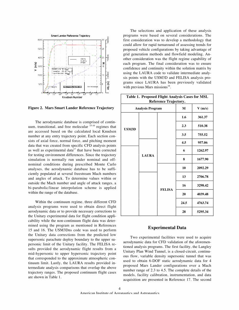
The aerodynamic database is provided as aFORTRAN routine containing specific vehicle forceand moment data as a function of vehicle orientationrelative to the flow and flowfield parameters to thePOST trajectory simulation. Within this routine, thevehicle trajectory is partitioned into three atmosphericregimes that are defined based on the similarity pa-rameter of Knudsen number. The Knudsen number(Kn) is defined as the mean free path (distance betweenmolecular collisions) divided by the vehicle referencelength (typically the aeroshell diameter). These atmos-pheric regimes are depicted in Figure 2.
4American Institute of Aeronautics and Astronautics
Figure 2. Mars Smart Lander Reference Trajectory
The aerodynamic database is comprised of contin-uum, transitional, and free molecular 15-16 regimes thatare accessed based on the calculated local Knudsennumber at any entry trajectory point. Each section con-sists of axial force, normal force, and pitching momentdata that was created from specific CFD analysis pointsas well as experimental data17 that have been correctedfor testing environment differences. Since the trajectorysimulation is normally run under nominal and off-nominal conditions during prescribed Monte Carloanalyses, the aerodynamic database has to be suffi-ciently populated at several freestream Mach numbersand angles of attack. To determine values within oroutside the Mach number and angle of attack ranges, abi-parabolic/linear interpolation scheme is appliedwithin the range of the database.
Within the continuum regime, three different CFDanalysis programs were used to obtain direct flightaerodynamic data or to provide necessary corrections tothe Unitary experimental data for flight condition appli-cability while the non-continuum flight data was deter-mined using the program as mentioned in References15 and 16. The USM3Dns code was used to performthe Unitary data corrections from the predicted lowsupersonic parachute deploy boundary to the upper su-personic limit of the Unitary facility. The FELISA re-sults provided the aerodynamic flight results from amid-hypersonic to upper hypersonic trajectory pointthat corresponded to the approximate atmospheric con-tinuum limit. Lastly, the LAURA results provided in-termediate analysis comparisons that overlap the abovetrajectory ranges. The proposed continuum flight casesare shown in Table 1.
The selections and application of these analysisprograms were based on several considerations. Thefirst consideration was to develop a methodology thatcould allow for rapid turnaround of assessing trends forproposed vehicle configurations by taking advantage ofgrid generation methods and flowfield modeling. An-other consideration was the flight regime capability ofeach program. The final consideration was to ensureconfidence and continuity within the solution matrix byusing the LAURA code to validate intermediate analy-sis points with the USM3D and FELISA analysis pro-grams since LAURA has been previously validatedwith previous Mars missions18.
Table 1. Proposed Flight Analysis Cases for MSLReference Trajectory.
Analysis Program M V (m/s)
1.6 361.37
2.3 510.38
3.5 755.52USM3D
4.5 957.06
6 1262.97
8 1677.90LAURA
10 2092.29
13 2706.78
16 3298.42
20 4039.48
24.5 4763.74
FELISA
28 5295.34
Experimental Data
Two experimental facilities were used to acquireaerodynamic data for CFD validation of the aforemen-tioned analysis programs. The first facility, the LangleyUnitary Plan Wind Tunnel, is a closed-circuit, continu-ous flow, variable density supersonic tunnel that wasused to obtain 6-DOF static aerodynamic data for 4proposed Mars Lander configurations over a Machnumber range of 2.3 to 4.5. The complete details of themodels, facility calibration, instrumentation, and dataacquisition are presented in Reference 17. The second

5American Institute of Aeronautics and Astronautics
facility, the 20-inch Mach 6 CF4 Tunnel, was used toobtain aerodynamic data for the Mars Surveyor con-figuration. The details of this work are presented inReference 19.
Results and Discussion
USM3Dns Validation
The USM3D code was required to validate its re-sults with Unitary tunnel experimental data in order toprovide confidence in correcting the Unitary Wind tun-nel data for the geometric differences between windtunnel and flight configuration and gas composition ofthe Mars atmosphere. Along with the previously de-scribed changes to USM3D, an unstructured mesh wasconstructed for the Baseline and Shelf-All tunnel con-figurations for a series of Mach numbers between 2.3and 4.5, each for a range of angles-of-attack values. Thegrid for the full Navier-Stokes solution varied in sizetypically from 1.4 million tetrahedral cells for the wind-tunnel cases to 2.6 million cells for the flight configu-rations. All the calculations were run for a Reynoldsnumber of 1.0 million based on the maximum diameterof the configuration (6 inches for the wind tunnel mod-els and 4.05 meters for the flight cases). The CFD caseswere run using up to 60 processors on an SGI Origin2000 computer. For all the computations reported here,a full viscous formulation was used. Some examples ofthe unstructured surface topology are depicted in Fig-ures 3 and 4.
Figure 3. Unstructured Surface Grid for the UnitaryBaseline Model Configuration.
Figure 4. Unstructured Surface Grid for the UnitaryShelf-All Model Configuration.
Figure 5 for the Baseline configuration shows theUSM3D/Unitary comparisons for freestream Machnumbers of 2.3 and 3.5. The axial and normal forcesalong with the pitching moment (about the nose) areshown. The CFD results for the tunnel conditions (g=1.4)compare well against the Unitary wind tunnel data, at-testing to the accuracy of the modified solver. The de-tailed comparisons show a better overall agreement atthe Mach 3.5 condition then at the lower Mach 2.3 con-dition while the Mach 2.3 condition also depictingsmaller differences in axial and normal force at 0 and 20degrees than the intermediate angle of attack range.
Figure 5. USM3D/Unitary Data Comparisons for theBaseline Configuration.
However, the USM3D analysis does predict a change innormal force slope near zero degrees angle of attack

6American Institute of Aeronautics and Astronautics
which is a known trend for axisymmetric blunt bodyconfigurations at low supersonic speeds.
Figure 6 shows the comparisons for the Shelf-Allconfiguration to the Unitary experimental data atfreestream Mach numbers of 2.3, 3.5 and 4.5. As withthe previous comparisons shown for the Baseline con-figuration, the overall agreement for Shelf-All configu-ration is very good. These comparisons show betteragreement in axial and normal force at lower Machnumbers than shown for the Baseline model while thepitching moment and L/D distribution shows excellentagreement throughout the Mach number and angle ofattack range.
Figure 6. USM3D/Unitary Data Comparisons for theShelf-All Configuration.
Figure 7 shows the comparisons for the Shelf-Allconfiguration to the Unitary experimental data under asideslip condition of 4 degrees. As with the previouscomparisons shown for the Baseline configuration, theoverall agreement for Shelf-All configuration is verygood. This particular case (6-DOF) was chosen in orderto increase the level of validation and thereby illustrateany deficiencies due to a geometry change and undersideslip conditions. These comparisons show a betteragreement in axial force and a similar difference innormal force as compared to the non-sideslipfreestream condition. Likewise, the comparisons to thepitching moment and L/D are excellent. Further as-sessment of CFD validation would require some solu-tions at lower angles of attack, but the overall assess-ment is extremely good. It should also be noted that thissideslip case was not used in the creation of the flightdatabase that is presented in this study.
Figure 7. USM3D/Unitary Data Sideslip Compari-sons for the Shelf-All Configuration (b=4o).
Figure 8 shows the comparisons for the Canted-Allconfiguration to the Unitary experimental data atfreestream Mach numbers of 2.3 and 3.5. As with theprevious comparisons shown for the Baseline configu-ration, the overall agreement for Canted-All configura-tion is very good. These comparisons show betteragreement throughout the Mach number and angle ofattack range for all force, moment and L/D quantities
Figure 8. USM3D/Unitary Data Comparisons for theCanted-All Configuration.
than those shown for the Baseline configuration. How-ever, additional solutions at lower angles of attackwould have to be made in order to obtain a more com-plete assessment of CFD validation.

7American Institute of Aeronautics and Astronautics
LAURA Validation
Although the LAURA analysis program has beenpreviously validated with Mars Pathfinder hypersonicflight data18, an attempt was made to provide additionalvalidation with the Unitary experimental data for a sin-gle Mars Smart Lander configuration at supersonicspeeds and to further validate USM3D. Figure 9 showsthe LAURA structured grid topology for the UnitaryBaseline configuration. This structured grid is com-prised of 16 computational blocks with an approximatetotal of 450,000 cell centers. In addition, this structuredgrid was adapted in the direction perpendicular to thebody surface as a function of the flowfield temperatureand grid distribution values.
Figure 9. Structured Grid for the Unitary BaselineModel Configuration
Figure 10 depicts the LAURA Mach number con-tours for the Baseline Unitary tunnel configuration forfreestream Mach number of 4.5 and an angle of attackof 10 degrees with no sideslip angle. This solution im-posed perfect gas air (g=1.4) at M=4.5 tunnel conditionswith a laminar, no-slip adiabatic wall boundary condi-tion. Figure 10 shows along the vehicle symmetry andoutflow planes the general flowfield characteristics ofan axisymmetric blunt body with dominant subsonicregions within the shock layer and vehicle base.
Figure 10. Mach Number Contours for the UnitaryBaseline Configuration – (M=4.5, a=10o)
Figure 11 depicts the LAURA/Unitary compari-sons for the Baseline Unitary tunnel configuration forfreestream Mach numbers of 2.3 and 4.5. These com-parisons overall show good agreement to the Unitarydata for all quantities. The axial force comparisonsshow better agreement at the higher angles of attack forboth Mach numbers while the normal force comparisonshows better agreement over the entire angle of attackrange at Mach 4.5 while the 10 degree case for Mach2.3 shows a larger difference as compared to theUSM3D/Unitary comparisons in Figure 5.
Figure 11. LAURA/Unitary Data Comparisons forthe Baseline Configuration.

8American Institute of Aeronautics and Astronautics
FELISA Validation
The FELISA validation work was centered aboutan earlier Mars 2001 Surveyor configuration that wastested in the 20-inch Mach 6 CF4 Tunnel. The MarsSurveyor configuration (Figure 12) was similar to MarsSmart Lander configuration, but differed in the controlflap geometry and location. The Mars Surveyor flapsurface area was at least 50 percent smaller and the flaporientation was 90 degrees perpendicular from the axisof rotation and located at aft of the maximum diameter.The number assigned to each control flap indicated thearea ratio of the flap where the larger number has agreater area ratio.
Figure 12. Mars 2001 Surveyor Wind Tunnel Model
Figures 13 and 14 depict the pitching moment co-efficient and L/D ratio for the Mars Surveyor configu-ration for Flap 1. The FELISA CF4 results showed verygood agreement to the experimental CF4 data compari-sons at 0, 5, 11, and 16 degrees angle of attack. In con-junction with a planned test in the 20-inch Mach 6 fa-cility, a FELISA analysis was performed using a CO2test gas as a freestream condition. The FELISA resultspredicted that the force and moment contributions to theL/D ratio at 0 degrees angle of attack would be insensi-tive to the CO2 test gas. However, the need for addi-tional results at different angles of attack would be nec-essary in order to determine a more generalized trend inCO2 insensitivity.
Figure 13. FELISA/CF4 Pitching Moment Compari-sons for the Mars Surveyor Configuration.
Figure 14. FELISA/CF4 L/D Comparisons for theMars Surveyor Configuration.
Figures 15 and 16 depict the pitching moment co-efficient and L/D ratio for the Mars Surveyor configu-ration with Flap 3. The FELISA CF4 results shows verygood agreement to the experimental CF4 data compari-sons at 0, 5, 11, and 16 degrees angle of attack. Thelarger Flap 3 configuration does show a slightly largerdeviation in pitching moment at 0 and 5 degrees ascompared to the Flap1, but overall agreement is stillvery good. These differences could be attributed to vis-cous contributions (not being modeled in FELISA) in-duced by the larger flap or an indication of a requiredincrease in control flap grid resolution.
0.029 Scale S ref = 7.07 in 2 L ref = 3 in
Dia = 3 in
Baseline forebody Flap #1
Flap #2 Flap #3
S flap S ref
= 0.02
S flap S ref
= 0.06 S flap S ref
= 0.04

9American Institute of Aeronautics and Astronautics
Figure 15. FELISA/CF4 Pitching Moment Compari-sons for the Mars Surveyor Configuration.
Figure 16. FELISA/CF4 L/D Comparisons for theMars Surveyor Configuration.
Flight Results – (Shelf-All Continuum Database)
For the continuum regime, an aerodynamic data-base was created for the Mars Smart Lander “Shelf-All”configuration using the USM3Dns correction analysesfor the Unitary experimental data (M=2.3-4.5), theLAURA intermediate analysis check points at Mach 4.5and 10, and the FELISA analyses at Mach 6, 8, 10, 24,and 28. Figures 17 and 18 show the continuum trimcharacteristics of the Shelf-All configuration based onthe axial CG locations of (x/Diameter) of 0.21 and 0.32.The CG of 0.21 corresponds to an early estimate of theMSL CG location while the 0.32 value corresponds toan L/D value of approximately 0.24 at a velocity of4700 m/s (Mach 24). In addition, the radial CG offsetfor this configuration was designed to be zero. For the
determination of ballistic coefficient, a mass of 2200kg. was used.
At the axial CG of 0.21, the trim angle of attackdepicts oscillatory behavior of 1 degree within theMach 2.3 to 4.5 Unitary experimental data range beforereaching a maximum value of 15.4 degrees at a velocityof approximately 1300 m/s (Mach 6). Beyond Mach 6,the trim angle of attack at the forward CG decreasesnearly linear to a continuum limit value of approxi-mately 12.8 degrees. Likewise, the L/D values depictthe same low supersonic behavior as well as the nearlylinear behavior beyond the maximum L/D of 0.266 atMach 4.5.
At the axial CG of 0.32, the trim angle of attackdepicts a larger variation in trim angle of attack ofabout 2.5 degrees within the Unitary data range andalso reaching a maximum of 16.9 degrees at a velocityof approximately 550 m/s (Mach 2.7) while reachinganother lower peak of 16.1 degrees at Mach 6. BeyondMach 6, the trim angle of attack at the 0.32 CG de-creases nearly linear to a continuum limit value of ap-proximately 13.6 degrees. As with the forward CG re-sults, the L/D shows a corresponding maximum valueat the peak trim reaching an overall maximum of 0.298.
Figure 17. L/D Continuum Trim Characteristics forShelf-All Configuration.
At trim conditions, the ballistic coefficient for theforward CG shows no low supersonic oscillatory be-havior while approaching a maximum of 114 at Mach 6while the axial CG of 0.32 showed the same distribu-tion while displaying a maximum of 116 at Mach 6. Asexpected, these results show a low sensitivity to CG

10American Institute of Aeronautics and Astronautics
location due to only a small (1%) difference in ballisticcoefficient over the entire continuum regime.
Figure 18. Ballistic Coefficient Continuum TrimCharacteristics for Shelf-All Configuration.
Flight Results–(Shelf-All Non-Continuum Database)
For the rarefied regime, an existing set of free mo-lecular data 2 over an angle of attack range of –180 to180 degrees was used in conjunction with bridgingfunction 20 to provide aerodynamic values within thetransition atmospheric regime. Figures 19 and 20 showthe trim characteristics for the Shelf-All configurationfrom the edge of continuum to a value of 20. A Knud-sen number (Kn) of 20 was sufficient to cover the rangeup to the atmospheric interface at approximately125000 meters above ground level.
Figure 19 shows the oscillatory behavior of thepitching moment within the transition regime. At thecontinuum limit and up to a Knudsen number of ap-proximately 5, there exists only a single trim point thatis also stable (negative Cma ). As the vehicle descendsthrough the transition regime, there are multiple condi-tions that the vehicle could potentially trim, but couldpotentially be an unstable or stable trim point. Figure 20displays Knudsen number and Cm alpha as a functionof trim angle of attack (a trim). For Knudsen numbersabove 2, there exist three trim angles of which 2 areunstable and 1 is stable. This information is neededwhile designing a guidance controller during the entryphase of the trajectory.
Figure 19. Non-Continuum Pitching Moment forShelf-All Configuration.
Figure 20. Non-Continuum Trim Characteristics forShelf-All Configuration.
Concluding Remarks
The CFD validation of USM3Dns and LAURAwith the Unitary experimental data, the use of interme-diate LAURA check analyses, as well as the validationof FELISA with the Mach 6 CF4 experimental data pro-vided very good agreement and a higher confidence ineach CFD code’s aerodynamic analysis results includ-ing the longitudinal static trim characteristics for theMars continuum atmosphere.

11American Institute of Aeronautics and Astronautics
Acknowledgments
The authors would like to thank Mr. Steve Alter ofthe NASA LaRC Aerothermodynamics Branch for cre-ating the structured grids used in the LAURA analysesand providing the surface topology used for theUSM3D unstructured grid generation. The authorswould also like to thank Mr. Ed Parlette of Vigyan Inc.for creating the unstructured grids used in the USM3Danalyses. In addition, thanks are due to Dr. Neil Cheat-wood of the NASA LaRC Exploration Programs Officefor his helpful recommendations and paper review.
References
1. Lockwood M.K., Powell R.W., Graves C.A. andCarman G.L. Entry System Design Considerationsfor Mars Landers, American Astronautical SocietyPaper No. 01-023, 24th AAS Guidance and ControlConference, January 31-February 4 2001, Brecken-ridge, CO.
2. Striepe S.A., Queen E.M., Powell R.W., BraunR.D., Cheatwood F.M., Aguirre J.T., Sachi L.A.and Lyons D.T., An Atmospheric Guidance Algo-rithm Testbed for Mars Surveyor Program 2001Orbiter and Lander, AIAA Paper 98-4569, Aug1998.
3. Braun R.D., Powell R.W., Cheatwood F.M.,Spencer D.A., and Mase R.A. The Mars Surveyor2001 Lander: A First Step Toward PrecisionLanding, 49th International Astronautical Congress,Melbourne, Australia, IAF-98-Q.3.03, Sept 28-Oct2 1998.
4. Bauer G.L., Cornick D.E., and Stevenson R., Ca-pabilities and Applications of the Program to Op-timize Simulated Trajectories (POST), NASA CR-2770, February 1977.
5. Frink N.T., Tetrahedral Unstructured Navier-Stokes Method for Turbulent Flows, AIAA Journal,Vol. 36, No. 11, pp. 1975-1982, November 1998.
6. Roe P.L., Approximate Riemann Solvers, Parame-ter Vectors, and Difference Schemes, Journal ofComputational Physics, Vol. 43, No. 2, pp. 357-372, October 1981.
7. Bhat M. K. and Parikh P. C., Parallel Implementa-tion of an Unstructured Grid-Based Navier-StokesSolver, AIAA Paper 99-0663, January 1999.
8. Wada Yasuhiro and Liou Meng-Sing, An Accurateand Robust Flux Splitting Scheme for Shock andContact Discontinuities, SIAM Journal of ScientificComputations, Vol. 18, No. 3, pp. 633-657, May1997.
9. Gnoffo P.A., An Upwind-Biased, Point-ImplicitRelaxation Algorithm for Viscous CompressiblePerfect Gas Flows, NASA TP 2953, Feb. 1990.
10. Cheatwood F. M. and Gnoffo P. A., User's Manualfor the Langley Aerothermodynamic Upwind Re-laxation Algorithm (LAURA), NASA TechnicalMemorandum 4674, April 1996.
11. Riley, C.J. and Cheatwood, F.M., Distributed-Memory Computing with the Langley Aerothermo-dynamic Upwind Relaxation Algorithm (LAURA),Advances in Engineering Software, Vol. 29, No. 3-6, July 1998, pp. 317-324.
12. Yee H.C., On Symmetric and Upwind TVDSchemes, NASA TM 86842, 1955.
13. Peiro J., Peraire J., and Morgan K., FELISA SystemReference Manual and Users Guide, NASA CP-3291, May 1995.
14. Bibb K.L., Peraire J., and Riley C.J., HypersonicFlow Computations On Unstructured Meshes,AIAA Paper 97-0625, January 1997.
15. Wilmoth R.G., LeBeau G.J., and Carlson A.B.,DSMC Grid Methodologies for Computing LowDensity Hypersonic Flows About Reusable LaunchVehicles, AIAA Paper 96-1812, June 1996.
16. Bird G.A., Molecular Gas Dynamics and DirectSimulation of Gas Flows, Clarendon Press, Oxford,1994.
17. Murphy K.J., Horvath T.J., Erickson G.E., andGreen J.M., Supersonic Aerodynamic Characteris-tics of Proposed Mars ’07 Smart Lander Configu-rations, AIAA 2002-4409, August 2002.
18. Gnoffo P.A., Braun R.D., Weilmuenster K.J.,Mitcheltree R.A., Engelund W.C., and PowellR.W., Prediction and Validation of Mars Path-finder Hypersonic Aerodynamic Database, Journalof Spacecraft and Rockets, Vol. 36 No. 3, May-June 1999.

12American Institute of Aeronautics and Astronautics
19. Horvath T.J., O’Connell T., Cheatwood F.M., andAlter S. Experimental Hypersonic AerodynamicCharacteristics of the Mars Surveyor 2001 Preci-sion Lander with Deployable Flap, AIAA 2002-4408, August 2002.
20. Celenligil M.C., Moss J.N. and Blanchard R.C.,Three-Dimensional Flow Simulation about theAFE Vehicle in the Transitional Regime, AIAA 89-0245, January 1989.