AIA Project Report on and Small Fragment Threat ... · PDF fileAnd Small Fragment Threat...
144
AIA Report On High Bypass Ratio Turbine Engine Uncontained Rotor Events And Small Fragment Threat Characterization Volume 1 1969 –2006 HIGH BYPASS COMMERCIAL TURBOFANS 1 AIA Project Report on High Bypass Ratio Turbine Engine Uncontained Rotor Events and Small Fragment Threat Characterization 1969-2006 Volume 1 January 2010
Transcript of AIA Project Report on and Small Fragment Threat ... · PDF fileAnd Small Fragment Threat...

AIA Report On High Bypass Ratio Turbine Engine Uncontained Rotor Events And Small Fragment Threat Characterization Volume 1
1969 –2006 HIGH BYPASS COMMERCIAL TURBOFANS 1
AIA Project Report
on
High Bypass Ratio Turbine Engine Uncontained Rotor Events
and
Small Fragment Threat Characterization
1969-2006
Volume 1
January 2010
AIA Report On High Bypass Ratio Turbine Engine Uncontained Rotor Events And Small Fragment Threat Characterization Volume 1
1969 –2006 HIGH BYPASS COMMERCIAL TURBOFANS 2
Contributing Organizations and Individuals
Ranee Carr AIA
Hubert Parinaud Airbus
Terrance Tritz Boeing Commercial Aircraft
Van Winters Boeing Commercial Aircraft
Thalerson Alves Embraer
Sarah Knife (Chair) General Electric
William Fletcher Rolls-Royce
Michael Young Pratt & Whitney
Douglas Zabawa Pratt & Whitney
AIA Report On High Bypass Ratio Turbine Engine Uncontained Rotor Events And Small Fragment Threat Characterization Volume 1
1969 –2006 HIGH BYPASS COMMERCIAL TURBOFANS 3
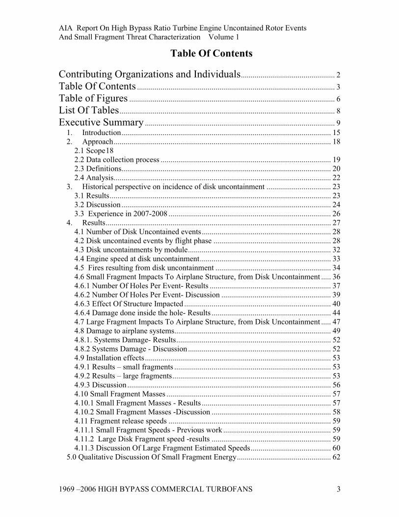
Table Of Contents
Contributing Organizations and Individuals................................................ 2 Table Of Contents ..................................................................................................... 3Table of Figures ......................................................................................................... 6 List Of Tables.............................................................................................................. 8 Executive Summary ................................................................................................. 9
1. Introduction........................................................................................................... 15 2. Approach............................................................................................................... 18
2.1 Scope 18 2.2 Data collection process ....................................................................................... 19 2.3 Definitions........................................................................................................... 20 2.4 Analysis............................................................................................................... 22
3. Historical perspective on incidence of disk uncontainment ................................. 23 3.1 Results................................................................................................................. 23 3.2 Discussion ........................................................................................................... 24 3.3 Experience in 2007-2008 ................................................................................... 26
4. Results................................................................................................................... 27 4.1 Number of Disk Uncontained events.................................................................. 28 4.2 Disk uncontained events by flight phase ............................................................ 28 4.3 Disk uncontainments by module......................................................................... 32 4.4 Engine speed at disk uncontainment................................................................... 33 4.5 Fires resulting from disk uncontainment ........................................................... 34 4.6 Small Fragment Impacts To Airplane Structure, from Disk Uncontainment ..... 36 4.6.1 Number Of Holes Per Event- Results .............................................................. 37 4.6.2 Number Of Holes Per Event- Discussion ........................................................ 39 4.6.3 Effect Of Structure Impacted ........................................................................... 40 4.6.4 Damage done inside the hole- Results ............................................................. 44 4.7 Large Fragment Impacts To Airplane Structure, from Disk Uncontainment ..... 47 4.8 Damage to airplane systems................................................................................ 49 4.8.1. Systems Damage- Results............................................................................... 52 4.8.2 Systems Damage - Discussion ......................................................................... 52 4.9 Installation effects............................................................................................... 53 4.9.1 Results – small fragments ................................................................................ 53 4.9.2 Results – large fragments................................................................................. 53 4.9.3 Discussion ........................................................................................................ 56 4.10 Small Fragment Masses .................................................................................... 57 4.10.1 Small Fragment Masses - Results .................................................................. 57 4.10.2 Small Fragment Masses -Discussion ............................................................. 58 4.11 Fragment release speeds ................................................................................... 59 4.11.1 Small Fragment Speeds - Previous work ....................................................... 59 4.11.2 Large Disk Fragment speed -results ............................................................. 59 4.11.3 Discussion Of Large Fragment Estimated Speeds......................................... 60
5.0 Qualitative Discussion Of Small Fragment Energy................................................ 62
AIA Report On High Bypass Ratio Turbine Engine Uncontained Rotor Events And Small Fragment Threat Characterization Volume 1
1969 –2006 HIGH BYPASS COMMERCIAL TURBOFANS 4
5.1 Small Fragment Energies – Trajectories And Collected Masses....................... 62 5.2 Small fragment energies – penetrations of aircraft structure .............................. 63 5.3 Phase II............................................................................................................... 64
6.0 Discussion ............................................................................................................... 66 6.1 Previous studies .................................................................................................. 66 6.1.2 Airplane-level consequence studies................................................................. 66 6.2 Probabilistic design goals ................................................................................... 69 6.3 Ricochets............................................................................................................ 71 6.4 Small Fragment Model ....................................................................................... 73
7.0 Conclusions............................................................................................................. 74 7.1 Disk uncontainment ............................................................................................ 74 7.2 Small Fragments Resulting From Disk Uncontainment ..................................... 75 7.3 Blade uncontainment .......................................................................................... 76
8.0 Recommendations................................................................................................... 77 9.0 References............................................................................................................... 79
Appendix 1 Disk Burst Event List................................................................................ 80 Appendix 2 Actions Taken To Prevent Disk Burst ...................................................... 81Appendix 3 Blade Non-Containment ........................................................................... 90
Summary....................................................................................................................... 90 A3.1 Introduction.......................................................................................................... 90 A3.2 Forward Arc Discussion ....................................................................................... 91
A3.2.1 Event Rates ................................................................................................... 92 A3.2.2 Discussion Of Rates ...................................................................................... 94 A3.2.3 Event Severity ............................................................................................... 98 A3.2.4 Qualitative Fragment Damage – Forward Arc............................................ 110 A3.2.5 Forward Arc Events And Flight Phase ....................................................... 110 A3.2.6 Installation Effects .................................................................................. 111
A3.3 Casing Uncontainment Of Blades....................................................................... 112 A3.3.1 Event Rates ............................................................................................. 112 A3.3.2 Discussion Of Rates................................................................................ 114 A3.3.3 Event Severity........................................................................................ 114 A3.3.4 Qualitative Fragment Damage – Casing Uncontained................................ 120 A3.3.5 Casing Uncontained Events And Flight Phase ........................................... 121 A3.3.6 Installation Effects ...................................................................................... 121
A3.4 Spinner Failures ................................................................................................. 123 A3.5 Material Exiting From The Exhaust .................................................................. 124
Appendix 4 Fan Spooldown Characteristics............................................................... 127 A4.1 Fan spooldown characteristics – technical considerations.................................. 127 A4.2 Engineering data ................................................................................................. 128
Appendix 5 Detailed Record of Impact Marks and Holes (located in Volume 2) ..... 130 Appendix 6 Airplane Fire Resulting From Disk Burst ............................................... 133
A6.1 Fuel source .................................................................................................... 133 A6.2 Ignition source............................................................................................... 133 A6.3 Fire control .................................................................................................... 133
Appendix 7 Large Fragment Velocity ........................................................................ 135 Appendix 8 Masses Of Collected Small Fragments ................................................... 141
AIA Report On High Bypass Ratio Turbine Engine Uncontained Rotor Events And Small Fragment Threat Characterization Volume 1
1969 –2006 HIGH BYPASS COMMERCIAL TURBOFANS 5
Appendix 9 CAAM Classifications ............................................................................ 142

AIA Report On High Bypass Ratio Turbine Engine Uncontained Rotor Events And Small Fragment Threat Characterization Volume 1
1969 –2006 HIGH BYPASS COMMERCIAL TURBOFANS 6
Table of Figures Figure 2.1 Debris trajectories............................................................................................ 18 Figure 2.2 Example of a large fragment ........................................................................... 20 Figure 2.3 Example of an intermediate fragment ............................................................. 20 Figure 2.4 Examples of small fragments. ........................................................................ 21 Figure 3.1 Annual Disk Uncontainments........................................................................ 23 Figure 3.2 Disk Uncontainment Rates .............................................................................. 24 Figure 3.3 Fleet utilization................................................................................................ 25 Figure 4.1 Distribution of Disk Uncontainments by Flight Phase.................................... 30 Figure 4.2 Distribution of Disk Uncontainments by Altitude .......................................... 31Figure 4.3 Distribution of Disk Uncontainments by Spool .............................................. 32 Figure 4.4 Engine Operating Speed At Time Of Disk Uncontainment ............................ 33 Commercial High Bypass Turbofan Fleet, 1969 – 2006 .................................................. 34Figure 4.5 Number of holes made by small fragments by spool...................................... 38 Figure 4.6 Number of holes made by small fragments by generation ............................. 38 Figure 4.7 Skin thickness vs holes per event .................................................................... 41 Figure 4.8 Skin thickness vs holes per event, in-air events only ...................................... 42 Figure 4.9 Holes and other witness marks ....................................................................... 43 Figure 4.10 Ability of structures to resist impact. ............................................................ 43 Figure 4.11 Ability of structures to resist impact; ratio of holes to impacts..................... 44 Figure 4.12 Damage to a second layer of structure by small fragments.......................... 46 Figure 4.13 Examples of events where disk burst resulted in systems damage which
reduced airplane controllability ................................................................................ 51 Figure 4.14 Number of holes in airplane structure made by small fragments .................. 53 Figure 4.15 Masses of small fragments retrieved from inside the airplane ...................... 58 Figure 4.16 Normalized masses of small fragments retrieved from inside the airplane... 58 Figure 4.17 Velocities of large disk fragments at escape from nacelle ............................ 60 Figure 6.1 Observed Severity Levels Of Disk Uncontainment Events ............................ 70 Figure A2.1 Primary Causes of Disk Uncontainments..................................................... 81 Figure A2.2 Disk burst causes, by decade ........................................................................ 84 Figure A2.3 Disk bursts resulting from material defects.................................................. 85 Figure A2.4 Disk bursts resulting from LCF................................................................... 86 Figure A2.5 Disk bursts resulting from dwell time fatigue .............................................. 86 Figure A2.6 Disk burst resulting from incorrect overhaul................................................ 87 Figure A2.7 Disk burst resulting from manufacturing (machining) damage.................... 87 Figure A2.8 Disk bursts resulting from overtemperature ................................................. 88 Figure A2.9 Disk bursts resulting from shaft separation .................................................. 88 Figure A2.10 Disk bursts resulting from fretting.............................................................. 89 Figure A3.1 Naming convention for uncontained debris.................................................. 91 Figure A3.2.1 Cumulative Number Of Forward Arc Events, 1969 – 2006...................... 92 Figure A3.2.2 Forward Arc Event Rates, 1969 – 2006 .................................................... 93 Figure A3.2.3 –Annual number of forward arc events .................................................... 93 Figure A3.2.4 Conventional fan blade with mid-span shroud; 18 oz pigeon ingestion. 96 Figure A3.2.5 Wide-chord blade; 8 lb pelican ingestion ................................................ 96 Figure A3.2.6 Location of the A-flange by high-bypass turbofan certification date ...... 97 Figure A3.2.7 Forward arc uncontainment – event severity ............................................ 98

AIA Report On High Bypass Ratio Turbine Engine Uncontained Rotor Events And Small Fragment Threat Characterization Volume 1
1969 –2006 HIGH BYPASS COMMERCIAL TURBOFANS 7
Figure A3.2.8 Fuselage dents (forward arc).................................................................. 102 Figure A3.2.9 Hole in outer window pane (forward arc).............................................. 103 Figure A3.2.10 2” puncture in stabilizer skin (forward arc) .................................... 103 Figure A3.2.11 Scratches on horizontal stabilizer (forward arc)................................... 104Figure A3.2.12 4” tear in fuselage skin (forward arc) ................................................... 104 Figure A3.2.13 Fuselage skin puncture (forward arc) .................................................... 105 Figure A3.2.14 Aileron dent (forward arc) ..................................................................... 105 Figure A3.2.15 3” gouge in fuselage skin (plugged); (forward arc)............................. 106 Figure A3.2.16 Fuselage patch over puncture (forward arc) ......................................... 106Figure A3.2.17 Right horizontal stabilizer holes (forward arc)...................................... 107 Figure A3.2.18 Plugged holes in fuselage ( forward arc)............................................... 107 Figure A3.2.19 2cm fuselage puncture (forward arc) .................................................. 108 Figure A3.2.20 Elevator puncture (forward arc) ........................................................... 108 Figure A3.2.21 Fuselage dent (forward arc) ................................................................ 109 Figure A3.2.22 Distribution of forward arc events by flight phase ................................ 110 Figure A3.3.1 Cumulative Number Of Casing Uncontained Blade Events, 1969 – 2006
................................................................................................................................. 112 Figure A3.3.2 Blade uncontainment rates....................................................................... 113 Figure A3.3.3 Blade uncontainment annual event count................................................ 113 Figure A3.3.4 Blade uncontainment; event severity....................................................... 114 Figure A3.3.5 Cabin window outer pane (case uncontained) ...................................... 115 Figure A3.3.6 Wing/body fairing and matching fuselage (case uncontained)............. 116 Figure A3.3.7 3” hole in slat (casing uncontained)....................................................... 116 Figure A3.5.1 Cut in aileron (tailpipe debris) ................................................................ 125 Figure A3.5.2 Elevator dent (tailpipe debris)............................................................... 125 Figure A3.5.3 Trailing edge flap holes (tailpipe debris) (photo taken during repair
process) 126 Figure A3.5.4 Nicks and dents to flaps, canoe fairings (tailpipe debris) ...................... 126 Figure A6.1 Incidence of fires resulting from disk burst (cumulative) .......................... 134 Figure A7.1 Estimated large fragment velocities on departing the nacelle .................... 136
AIA Report On High Bypass Ratio Turbine Engine Uncontained Rotor Events And Small Fragment Threat Characterization Volume 1
1969 –2006 HIGH BYPASS COMMERCIAL TURBOFANS 8
List Of Tables Table 4.1 Commercial High Bypass Turbofan Disk Uncontainment Statistics, 1969 -
2006........................................................................................................................... 28 Table 4.2 Summary Of Fire Experience Resulting From Disk Uncontained Events ...... 34 Table 4.3 Airplane damage produced by uncontained disk – small fragments ................ 37 Table 4.4; Average Number Of Holes Made By Small Fragments (including ricochet
events) ....................................................................................................................... 39 Table 4.5; average number of holes made by small fragments (excluding ricochet events)
................................................................................................................................... 40 Table 4.6 Shielding Effect Of Wing Against Large And Intermediate Disk Pieces......... 48 Table 4.7 Events With Systems Damage Which Reduced Airplane Controllability........ 50 Table 4.8 Containment/ Deflection Of Disk Fragments By Structure.............................. 56 Table 5.1Fragment Masses – Collected Fragments .......................................................... 62 Table 5.2 Fragment Speeds – Extrapolating From Large To Small Fragments ............... 63 Table 5.3. Small Fragment Energy Estimates................................................................... 63 Table A1.1 Uncontained Disk Events............................................................................... 80 Table A2.1 Milestones in Turbine Rotor Integrity Improvements ................................... 84 Table A3.1 Milestones in Turbofan Blades Integrity/ Containment Improvements ....... 95 Table A3.2 Incidence of level 2 forward arc events ......................................................... 98 Table A3.3 Airplane damage from forward arc non-containment (CAAM level 2 and
higher) ..................................................................................................................... 100 Table A3.4 Installation effects in tri-jets; forward arc events ........................................ 111 Table A3.5 Incidence of level 2 casing uncontained events........................................... 117 Table A3.6 Airplane damage from blade non-containment by casings (excluding
forward arc) (CAAM level 2 and higher) ............................................................... 118 Table A3.7 Spinner uncontainment ................................................................................ 123 Table A3.7 Airplane damage from tailpipe debris (excluding events with forward arc or
casing non-containment) ......................................................................................... 124 Table A4.1 Spooldown times with high unbalance ........................................................ 129 Table A5.1 Tally of holes made by small fragments ...................................................... 132 Table A6.1 Fires resulting from disk burst ..................................................................... 133
AIA Report On High Bypass Ratio Turbine Engine Uncontained Rotor Events And Small Fragment Threat Characterization Volume 1
1969 –2006 HIGH BYPASS COMMERCIAL TURBOFANS 9
Executive Summary
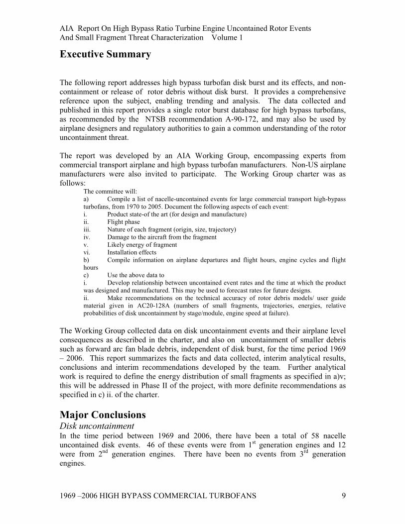
The following report addresses high bypass turbofan disk burst and its effects, and non-containment or release of rotor debris without disk burst. It provides a comprehensive reference upon the subject, enabling trending and analysis. The data collected and published in this report provides a single rotor burst database for high bypass turbofans, as recommended by the NTSB recommendation A-90-172, and may also be used by airplane designers and regulatory authorities to gain a common understanding of the rotor uncontainment threat.
The report was developed by an AIA Working Group, encompassing experts from commercial transport airplane and high bypass turbofan manufacturers. Non-US airplane manufacturers were also invited to participate. The Working Group charter was as follows:
The committee will: a) Compile a list of nacelle-uncontained events for large commercial transport high-bypass turbofans, from 1970 to 2005. Document the following aspects of each event: i. Product state-of the art (for design and manufacture) ii. Flight phase iii. Nature of each fragment (origin, size, trajectory) iv. Damage to the aircraft from the fragment v. Likely energy of fragment vi. Installation effects b) Compile information on airplane departures and flight hours, engine cycles and flight hours c) Use the above data to i. Develop relationship between uncontained event rates and the time at which the product was designed and manufactured. This may be used to forecast rates for future designs. ii. Make recommendations on the technical accuracy of rotor debris models/ user guide material given in AC20-128A (numbers of small fragments, trajectories, energies, relative probabilities of disk uncontainment by stage/module, engine speed at failure).
The Working Group collected data on disk uncontainment events and their airplane level consequences as described in the charter, and also on uncontainment of smaller debris such as forward arc fan blade debris, independent of disk burst, for the time period 1969 – 2006. This report summarizes the facts and data collected, interim analytical results, conclusions and interim recommendations developed by the team. Further analytical work is required to define the energy distribution of small fragments as specified in a)v; this will be addressed in Phase II of the project, with more definite recommendations as specified in c) ii. of the charter.
Major Conclusions Disk uncontainment In the time period between 1969 and 2006, there have been a total of 58 nacelle uncontained disk events. 46 of these events were from 1st generation engines and 12 were from 2nd generation engines. There have been no events from 3rd generation engines.

AIA Report On High Bypass Ratio Turbine Engine Uncontained Rotor Events And Small Fragment Threat Characterization Volume 1
1969 –2006 HIGH BYPASS COMMERCIAL TURBOFANS 10
The overall occurrence rate of disk burst (includes spacers) has fallen by over 2 orders of magnitude since high bypass ratio engines entered service. This reduction results from a series of industry and regulatory initiatives, directed at controlling and progressively reducing or eliminating the root causes of disk burst . There were no third generation disk burst events in the study period; if there had been one, the third generation cumulative rate would be 2.5 E-8/cycle). The incidence of disk burst for future design high bypass turbofans will likely be at least as good as that of third generation engines.
The high bypass turbofan fleet, as a whole, has experienced 58 disk uncontainment events over the time period considered, three of which resulted in loss of the airplane. The results are consistent with the 1 in 20 criterion used during certification analysis, even though many (75%) of the events occurred on airplanes designed and certified before introduction of this criterion. A probabilistic criterion for minimizing the effects of disk burst was proposed in the mid-1970s (Reference 3). It required that, given a disk burst, there should be no more than a 1 in 20 chance of a Catastrophic outcome from impact by a 1/3 disk fragment. So far, airplanes designed using that criterion and the associated mitigating design features have shown sufficient system robustness for continued safe flight after disk burst. In contrast, first generation high-bypass turbofan airplanes, which were designed before the criterion was published, have experienced systems damage affecting controllability on multiple occasions. The damage instances to systems which affected airplane controllability all took place very close to the affected engine; within one or two nacelle diameters. In each case, the systems damage was from large or intermediate size fragments, or was to systems shielded by very light skin (.02” aluminum).
The estimated third generation disk uncontainment rates, in conjunction with the historical observed hazard ratio for Catastrophic damage from 1/3 disk, provides a level of risk which is approaching an extremely improbable condition, commensurate with other accepted airplane design risks.
More than 90% of disk bursts occur at low altitude (well below the 25,000 ft cited in 14 CFR Part 25 Section 25.863). These events have occurred during takeoff or initial (low altitude) climb.
Fires resulting from disk burst inflight have been controlled with the use of fuel shutoff means with no hazardous outcomes. On the ground, uncontrolled fires have resulted when significant quantities of fuel pools on the ground as a result of tank rupture following ground ricochet. No fatal injuries have resulted from these events.
There is evidence that nacelle and airplane heavy structure provides some degree of shielding from large and intermediate fragments. In most cases where a large or intermediate fragment hit the wing, it did not pass through the wing, indicating that the wing provides some significant degree of shielding against a realistic large fragment.

AIA Report On High Bypass Ratio Turbine Engine Uncontained Rotor Events And Small Fragment Threat Characterization Volume 1
1969 –2006 HIGH BYPASS COMMERCIAL TURBOFANS 11
Nacelle structure provides some containment or shielding capability for large and intermediate fragments.
The evidence of engine test and service experience indicates that in the event of a disk burst or loss of an entire fan blade, the engine is likely to stall very rapidly, cease producing useful thrust, and spool down. It is considered highly unlikely that a disk burst resulting in deployment of a reverser would produce significant reverse thrust effects. It is considered very likely that an engine departing the airplane as a result of disk burst would drop away without any significant thrust vector.
Small Fragments Resulting From Disk Uncontainment
Preliminary analysis of structural damage suggests that small fragments may have much lower energies than has previously been assumed. Most small fragments do not have enough energy to make holes in airplane structure. Of 8700 small fragment impacts, 450 made holes in the airplane. Most small fragments which make holes in the airplane do not have enough residual energy to damage systems or additional structural layers inside the hole. Of 450 small fragment holes, 27 fragments went on to damage systems or structure inside the hole.
Analysis of a limited set of large disk fragment trajectories indicates that they were released from the engine at considerably lower speed than their tangential speed immediately prior to burst. Speeds based on trajectories, for this limited set, were less than 30% of pre-burst speeds. Consequently, small fragments may also have much lower speeds than their tangential speed prior to burst.
Blade uncontainment
The rate of forward arc fan blade fragment non-containment has been reduced by several orders of magnitude since the first high bypass turbofans entered service. Recent designs of engines such as wide-chord fan blade designs have lower rates than the earlier generations of high bypass turbofans.
The airplane level consequences of fan blade fragment forward arc non-containment are usually limited to a small number of superficial nicks, dents and holes in aerodynamic surfaces. A few events have resulted in one or two small holes in the pressure skin (of the order of two inches across). There has been one level 3 event due to forward-arc uncontainment; this involved damage to a hydraulic system in an adjacent engine strut/pylon.
Design improvements have reduced the rate of casing uncontainment by blades by a factor of 50 since the first high bypass fans entered service. The airplane level consequences of casing uncontainment by blades vary according to the specific failure mode involved. Most events result in a small number of superficial nicks, dents and holes in aerodynamic surfaces. The release of multiple whole fan blades, or LPT vane/ nozzle spinning has resulted in more extensive damage.
AIA Report On High Bypass Ratio Turbine Engine Uncontained Rotor Events And Small Fragment Threat Characterization Volume 1
1969 –2006 HIGH BYPASS COMMERCIAL TURBOFANS 12
Debris exiting through the tailpipe has been low energy and has not caused hazardous effects or the potential thereof.
Major Recommendations
The data in this report is recommended for use in interpretation of existing policy and guidance. 1. In particular, when addressing mitigation, the following points should be considered:
The low incidence of disk uncontainment demonstrated by the 2nd/3rd generation fleet. The continued emphasis on rotor integrity by design, manufacturing, and maintenance which has resulted in a steady reduction of the historical disk burst rate, both for existing engine models and for new models developed using lessons learned . The demonstrated systems robustness of airplanes designed to comply with the 1 in 20 criterion of a catastrophic outcome resulting from damage by a 1/3 disk fragment.The very low probability of disk burst occurring above 25,000 ft, and low consequent probability of high-altitude depressurization from disk burst. The relative likelihood of disk burst from different spools The minimal airplane damage caused by blade forward arc uncontainment and by tailpipe debris. The role of rapid spooldown of engines in avoiding significant inflight thrust reversal as a result of disk burst. The role of rapid spooldown of engines in avoiding catastrophic airplane damage from engine separation after disk burst.
2. Recognizing today’s current disk burst rates, and recognizing the historical 3 in 58 observed probability of disk burst leading to a Catastrophic outcome (from any and all fragment sizes), it is recommended that airplane designs which meet the 1 in 20 probabilistic criterion for a Catastrophic outcome from disk burst (large disk fragment) be interpreted as having met the intent of minimizing the hazard from rotor burst.
3. Airplane pressure skins in the locations of debris damage are typically .05 to .08” Al 2024. The data indicates that .05” to .08” aluminum will protect against system damage by over 96% of small fragments. This data supports the use of shielding equivalent to pressure cabin skins, as recommended in AC20-128A.
4. Further work is recommended in phase II, to quantify the energies of small fragments based on the observed damage to airplane structure. This will enable assessment of the degree of shielding provided by materials other than sheet aluminum.
5. It is recommended that redundant critical systems be located out of the near-field zone, as far as is practicable, since the density of the small fragment debris pattern is
AIA Report On High Bypass Ratio Turbine Engine Uncontained Rotor Events And Small Fragment Threat Characterization Volume 1
1969 –2006 HIGH BYPASS COMMERCIAL TURBOFANS 13
very much greater close to the engine. It is also recommended that mitigation of the effects of disk burst focus on near-field systems routing and robustness.
6. Since the data shows that existing aircraft structure provides adequate protection against small fragments, away from the near-field zone, it is recommended that the current requirements should not be expanded to require probabilistic assessment for small fragments.
7. The use of small fragment energy based on ½ or 1/3 airfoil at the tangential speed immediately prior to burst is not recommended. A recommendation for a representative small fragment energy will be made once Phase II has quantified the small fragment energy distribution more exactly.
8. It is recommended that debris from fan blade forward arc travel and tailpipe debris continue to be regarded as low energy and as not presenting a threat to passengers or airplane systems.
9. The interpretation and application of 14 CFR Part 25 Section 25.841 should be reviewed to consider taking into account the low rate of disk burst in recent designs and the distribution of disk burst by flight phase and altitude. It should also take into account the relative improbability of the LP spool encountering a disk burst on the second/third generation engines. Elements which should be considered are:
Disk burst rate of <2.5E-8/engine cycle Proportions of disk bursts above 25,000 ft (bounded by 1 in 14 for second/third generation fleet , assuming 1 event although none have occurred Relative frequencies of disk burst by spool for second/third generation fleet
10. It is recommended that future data collection and analysis discriminate between events above and below 25,000 ft
AIA Report On High Bypass Ratio Turbine Engine Uncontained Rotor Events And Small Fragment Threat Characterization Volume 1
1969 –2006 HIGH BYPASS COMMERCIAL TURBOFANS 14
Project Charter
The committee will: a) Compile a list of nacelle-uncontained events for large commercial transport high-bypass turbofans, from 1970 to 2005. Document the following aspects of each event: i. Product state-of the art (for design and manufacture) ii. Flight phase iii. Nature of each fragment (origin, size, trajectory) iv. Damage to the aircraft from the fragment v. Likely energy of fragment vi. Installation effects b) Compile information on airplane departures and flight hours, engine cycles and flight hours c) Use the above data to i. Develop relationship between uncontained event rates and the time at which the product was designed and manufactured. This may be used to forecast rates for future designs. ii. Make recommendations on the technical accuracy of rotor debris models/ user guide material given in AC20-128A (numbers of small fragments, trajectories, energies, relative probabilities of disk uncontainment by stage/module, engine speed at failure).
AIA Report On High Bypass Ratio Turbine Engine Uncontained Rotor Events And Small Fragment Threat Characterization Volume 1
1969 –2006 HIGH BYPASS COMMERCIAL TURBOFANS 15
1. Introduction
Turbine engine uncontained events have long been recognized as a major threat for airplane safety in the commercial transport fleet. The dramatic nature of uncontained rotor events and the risk they present to the airplane has prompted numerous studies of the subject. The historical material captured by the studies has varied widely, as the teams identified new areas of interest, calendar time period reporting constraints, or recognized previous difficulties encountered during analysis and publication. This variation has made it difficult to develop a unified and coherent perspective of the subject over time. For example, it has not been possible to review the disk uncontainment rate for high bypass turbofans over the last 30 years because previous studies used differing metrics of fleet usage and varying definitions of the engine population for which data was collected. This work updates and amplifies upon the previous reports addressing this subject.
Over the last 20 years, the need has been recognized for a database from which to draw a common understanding of the nature of uncontained events. In 1990, in the aftermath of an accident where the debris from an uncontained fan disk damaged all hydraulic systems on an airplane , leading to loss of control, the NTSB published a letter saying: The Safety Board is concerned that there may not be a central repository for a current and complete data base for engine rotating part noncontainment events. The Safety Board believes that the FAA should review the current reporting requirements for manufacturers and operators to establish a centrally available data base of these events based on operator and engine manufacturer knowledge and in-service experience. The Safety Board recommends that the FAA establish a system to monitor the engine rotary parts failure history of turbine engines and to support a data base sufficient for design assessment, comparative safety analysis among manufacturers, and more importantly, to establish a verifiable background for the FAA to research during certification review.
Responses to the NTSB letter included convening an SAE committee to research non containment events1, publication of Advisory Circular 39-8, and compilation of a database of uncontained events as part of the FAA Airplane Catastrophic Failure Prevention program. The Powerplant Installations Harmonization Working Group (PPIHWG), within ARAC, attempted to revise AC 20-128A using the results derived from this database, as documented in (China Lake Report). The PPIHWG group was unable to reach consensus on defining the small fragment model; contributing factors included: �� A mismatch between the proposed fragment model synthesized from the database
and the distilled experience of the industry accident investigators and analysts. It transpired that the database had only incorporated the worst-case events, due to a misunderstanding at the time of compilation over the intended use of the database.
�� Difficulties in accessing the original data for alternative analysis and review.
1 The SAE committee prepared a draft study which was not subsequently published.
AIA Report On High Bypass Ratio Turbine Engine Uncontained Rotor Events And Small Fragment Threat Characterization Volume 1
1969 –2006 HIGH BYPASS COMMERCIAL TURBOFANS 16
�� Group attention being fragmented between the proposed fragment model, the proposed revisions to the Advisory Circular, and tracking the ballistics research and rotor burst modeling code (UEDAM) being developed under the Airplane Catastrophic Failure Prevention initiative.
The Mechanical Systems Harmonization Working Group concurrently asked for assistance from PPIHWG in evaluating the issue of decompression as a result of rotor burst; assistance was limited to that available from individual industry members since the database was not found to incorporate the relevant information. This report makes that information on rotor burst altitude and flight phase generally available for design assessment and safety analysis. Furthermore, the data in this report may be used to show that some other concerns raised in previous regulatory or certification work, based on the partial information available at that time, may already be mitigated by inherent features of the gas turbine engine and the statistical distribution of uncontainment events. Examples include in-flight deployment of thrust reversers and long-range fuel reserves.
Since the early 1990s, the additional focus on compliance with the rotor burst regulations (in particular 14 CFR Part 25 Section 25.903(d) and equivalents) has revealed widespread differences in interpretation of these regulations; the differences are growing with each certification Applicants have developed internal requirements and guidelines in an attempt to predict how the rule will be interpreted; these may be more or less conservative than intended by the authorities and may therefore introduce unwarranted airplane performance penalties and/or certification risk. This report provides the facts and data to establish a common understanding of the rotor uncontained disk and blade events for high bypass turbofans. It may be used to predict the likely nature of future uncontainment events, to assess the magnitude of possible risks, and to prioritize mitigating actions. The existence of a common reference source, addressing airplane effects of rotor burst, should promote a common understanding of the threat for industry and regulatory authorities.
This report provides a common database of older and more recent events on high bypass turbofan engines, to enable assessment of how the issue of rotor uncontainment has changed over time, in support of NTSB recommendation A-90-172. The current situation can be seen in the context of the past, so that appropriate goals and standards can be agreed upon. The report identifies uncontained rotor rates and trends for both rotor disk and blade uncontained events, damage level assessment2, phase of flight summaries and engine design generation differences. In addition, this report also presents data not captured before and considered potentially useful for current airplane and engine design communities, as follows: �� Flight phase, with discrimination between high altitude and low altitude events �� Engine operating speed at disk uncontainment
2 Includes cross-engine debris
AIA Report On High Bypass Ratio Turbine Engine Uncontained Rotor Events And Small Fragment Threat Characterization Volume 1
1969 –2006 HIGH BYPASS COMMERCIAL TURBOFANS 17
�� Airplane effects of disk uncontainment – fires, event severity �� Small fragment characterization and qualitative description of energy levels
Furthermore, this report has collected data on rotor blade non-containment events, and on events where blade material was released without penetrating the engine casing structure – forward arc uncontainment and tailpipe debris ejection.
This report may be used as source material in support of continued airworthiness assessments for potential safety implications, rulemaking or advisory material development or as the historical basis for development of an applicant’s type certification. A second report is planned to be published addressing quantitative energy of small fragments, once the relevant analysis has been completed.
AIA Report On High Bypass Ratio Turbine Engine Uncontained Rotor Events And Small Fragment Threat Characterization Volume 1
1969 –2006 HIGH BYPASS COMMERCIAL TURBOFANS 18
2. Approach 2.1 Scope
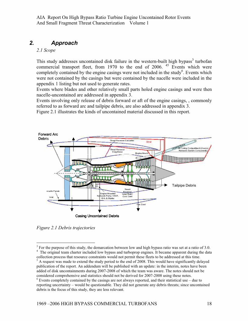
This study addresses uncontained disk failure in the western-built high bypass3 turbofan commercial transport fleet, from 1970 to the end of 2006. 45 Events which were completely contained by the engine casings were not included in the study6. Events which were not contained by the casings but were contained by the nacelle were included in the appendix 1 listing but not used to generate rates. Events where blades and other relatively small parts holed engine casings and were then nacelle-uncontained are addressed in appendix 3. Events involving only release of debris forward or aft of the engine casings, , commonly referred to as forward arc and tailpipe debris, are also addressed in appendix 3. Figure 2.1 illustrates the kinds of uncontained material discussed in this report.
Figure 2.1 Debris trajectories
3 For the purpose of this study, the demarcation between low and high bypass ratio was set at a ratio of 3.0. 4 The original team charter included low bypass and turboprop engines. It became apparent during the data collection process that resource constraints would not permit these fleets to be addressed at this time. 5 A request was made to extend the study period to the end of 2008. This would have significantly delayed publication of the report. An addendum will be published with an update: in the interim, notes have been added of disk uncontainments during 2007-2008 of which the team was aware. The notes should not be considered comprehensive and statistics should not be derived for 2007-2008 using these notes. 6 Events completely contained by the casings are not always reported, and their statistical use – due to reporting uncertainty – would be questionable. They did not generate any debris threats; since uncontained debris is the focus of this study, they are less relevant.
Casing Uncontained Debris
Tailpipe Debris
Forward Arc Debris
Casing Uncontained Debris
Tailpipe Debris
Casing Uncontained Debris
Tailpipe Debris
Forward Arc Debris
AIA Report On High Bypass Ratio Turbine Engine Uncontained Rotor Events And Small Fragment Threat Characterization Volume 1
1969 –2006 HIGH BYPASS COMMERCIAL TURBOFANS 19
Military use of commercial airplanes was excluded due to the dissimilarity between the commercial and military environments. Events occurring in test stands (not installed) were also excluded since they would not give insight into airplane effects. Various rotating structures like drum spools, spacers and mini-disks forming seal supports are significantly heavier than blades, but of lighter construction than deep-bore disks and these structures have been grouped with disks for statistical study. Spinner uncontained events were included as a separate dataset.
2.2 Data collection process The team included representatives from: AIA Airbus Boeing Embraer FAA General Electric Pratt & Whitney Rolls-Royce Each manufacturer submitted data on the events involving their products for the specified time period. Where details of the same event differed between two manufacturers, the discrepancy was resolved between the two principals in a side-discussion.7 The level of detail available for an event varied considerably; ranging from a short paragraph summary to a detailed report with high-quality photographs. Depending on the event geographical location, the level of investigative coverage by agencies and OEMs had a significant outcome on the level of documentation detail. It can be assumed that major damage to the airplane was well-reported; minor damage which could be repaired immediately was likely not reported in many cases. The uncontained events were assigned severities based on the CAAM (references 7, 8) classification of the effects which had actually occurred (not those effects which could potentially have occurred). The CAAM severity classifications relating to uncontained engine effects are provided in appendix 9. The two disk post failures were not included in the disk data, because they only generated small fragments and they caused no airplane damage beyond the affected nacelle. Manufacturers also submitted data on the annual hours and cycles of their products to enable event rates to be calculated.
The data was sanitized before incorporation into the final report, and interim (non-sanitized) versions destroyed.
7 For the purposes of this study only, event severities were assigned based on the effects due to fragments being uncontained, rather than to every effect which occurred in the course of the event. For example, if uncontained material holed a fuel tank and therefore caused a fire, the fire was included in the event categorization. If an uncontained event occurred and caused a high speed rejected take-off (RTO), that RTO would have occurred regardless of the engine debris being contained or otherwise, and so the RTO was not considered in assigning severities. If an uncontained event occurred and an engine cowling fell off due to high unbalance, the effects of cowling departure would not be used to derive the CAAM severity. The intent was to focus attention on the effect of the non-containment.
AIA Report On High Bypass Ratio Turbine Engine Uncontained Rotor Events And Small Fragment Threat Characterization Volume 1
1969 –2006 HIGH BYPASS COMMERCIAL TURBOFANS 20
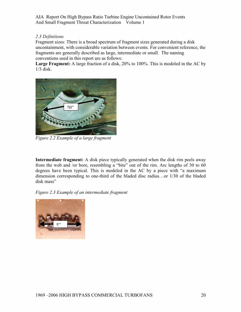
2.3 Definitions Fragment sizes: There is a broad spectrum of fragment sizes generated during a disk uncontainment, with considerable variation between events. For convenient reference, the fragments are generally described as large, intermediate or small. The naming conventions used in this report are as follows: Large Fragment: A large fraction of a disk, 20% to 100%. This is modeled in the AC by 1/3 disk.
Figure 2.2 Example of a large fragment
Intermediate fragment: A disk piece typically generated when the disk rim peels away from the web and /or bore, resembling a “bite” out of the rim. Arc lengths of 30 to 60 degrees have been typical. This is modeled in the AC by a piece with “a maximum dimension corresponding to one-third of the bladed disc radius…or 1/30 of the bladed disk mass”
Figure 2.3 Example of an intermediate fragment
20”
5”
AIA Report On High Bypass Ratio Turbine Engine Uncontained Rotor Events And Small Fragment Threat Characterization Volume 1
1969 –2006 HIGH BYPASS COMMERCIAL TURBOFANS 21
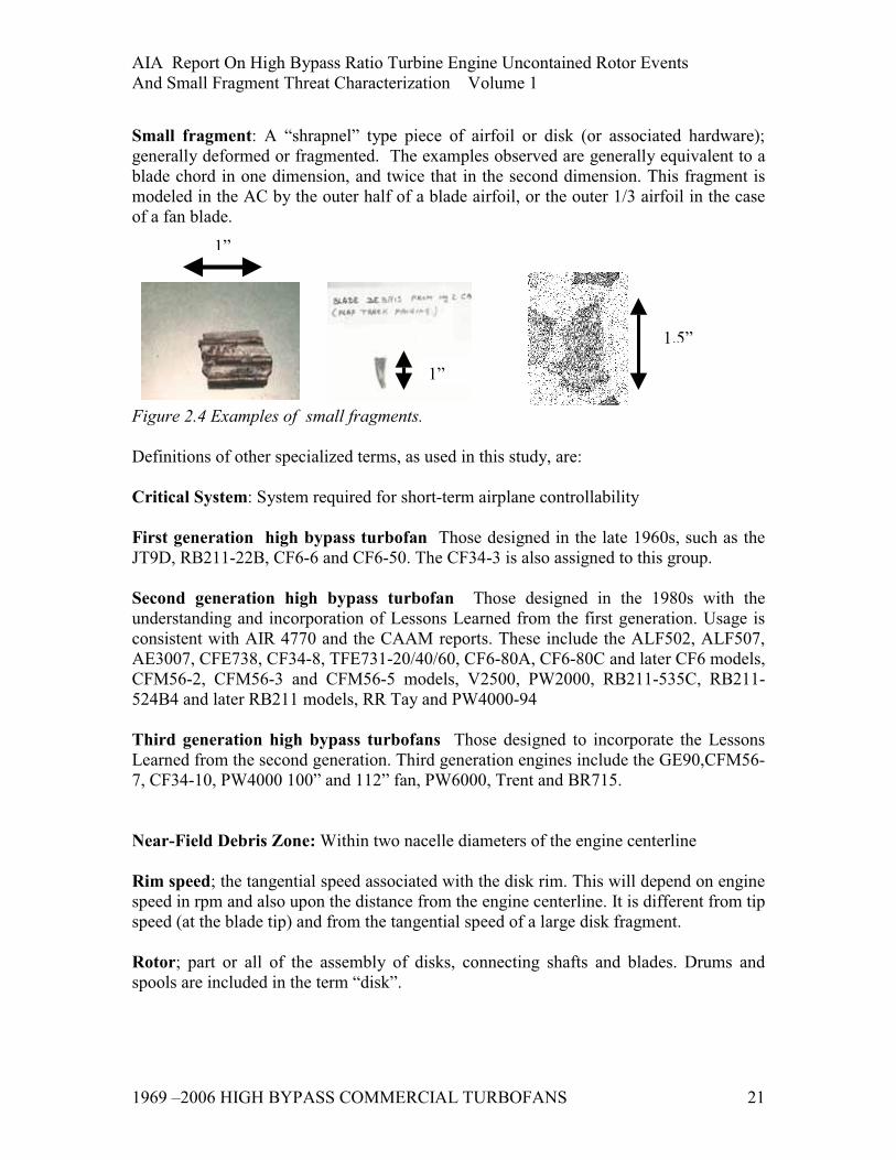
Small fragment: A “shrapnel” type piece of airfoil or disk (or associated hardware); generally deformed or fragmented. The examples observed are generally equivalent to a blade chord in one dimension, and twice that in the second dimension. This fragment is modeled in the AC by the outer half of a blade airfoil, or the outer 1/3 airfoil in the case of a fan blade.
Figure 2.4 Examples of small fragments.
Definitions of other specialized terms, as used in this study, are:
Critical System: System required for short-term airplane controllability
First generation high bypass turbofan Those designed in the late 1960s, such as the JT9D, RB211-22B, CF6-6 and CF6-50. The CF34-3 is also assigned to this group.
Second generation high bypass turbofan Those designed in the 1980s with the understanding and incorporation of Lessons Learned from the first generation. Usage is consistent with AIR 4770 and the CAAM reports. These include the ALF502, ALF507, AE3007, CFE738, CF34-8, TFE731-20/40/60, CF6-80A, CF6-80C and later CF6 models, CFM56-2, CFM56-3 and CFM56-5 models, V2500, PW2000, RB211-535C, RB211-524B4 and later RB211 models, RR Tay and PW4000-94
Third generation high bypass turbofans Those designed to incorporate the Lessons Learned from the second generation. Third generation engines include the GE90,CFM56-7, CF34-10, PW4000 100” and 112” fan, PW6000, Trent and BR715.
Near-Field Debris Zone: Within two nacelle diameters of the engine centerline
Rim speed; the tangential speed associated with the disk rim. This will depend on engine speed in rpm and also upon the distance from the engine centerline. It is different from tip speed (at the blade tip) and from the tangential speed of a large disk fragment.
Rotor; part or all of the assembly of disks, connecting shafts and blades. Drums and spools are included in the term “disk”.
1”
1”
1.5”
AIA Report On High Bypass Ratio Turbine Engine Uncontained Rotor Events And Small Fragment Threat Characterization Volume 1
1969 –2006 HIGH BYPASS COMMERCIAL TURBOFANS 22
2.4 Analysis
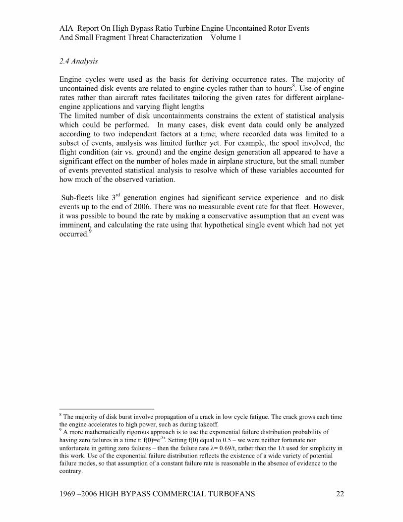
Engine cycles were used as the basis for deriving occurrence rates. The majority of uncontained disk events are related to engine cycles rather than to hours8. Use of engine rates rather than aircraft rates facilitates tailoring the given rates for different airplane-engine applications and varying flight lengths The limited number of disk uncontainments constrains the extent of statistical analysis which could be performed. In many cases, disk event data could only be analyzed according to two independent factors at a time; where recorded data was limited to a subset of events, analysis was limited further yet. For example, the spool involved, the flight condition (air vs. ground) and the engine design generation all appeared to have a significant effect on the number of holes made in airplane structure, but the small number of events prevented statistical analysis to resolve which of these variables accounted for how much of the observed variation.
Sub-fleets like 3rd generation engines had significant service experience and no disk events up to the end of 2006. There was no measurable event rate for that fleet. However, it was possible to bound the rate by making a conservative assumption that an event was imminent, and calculating the rate using that hypothetical single event which had not yet occurred.9
8 The majority of disk burst involve propagation of a crack in low cycle fatigue. The crack grows each time the engine accelerates to high power, such as during takeoff. 9 A more mathematically rigorous approach is to use the exponential failure distribution probability of having zero failures in a time t; f(0)=e-�t. Setting f(0) equal to 0.5 – we were neither fortunate nor unfortunate in getting zero failures – then the failure rate �= 0.69/t, rather than the �/t used for simplicity in this work. Use of the exponential failure distribution reflects the existence of a wide variety of potential failure modes, so that assumption of a constant failure rate is reasonable in the absence of evidence to the contrary.
AIA Report On High Bypass Ratio Turbine Engine Uncontained Rotor Events And Small Fragment Threat Characterization Volume 1
1969 –2006 HIGH BYPASS COMMERCIAL TURBOFANS 23
3. Historical perspective on incidence of disk uncontainment
Note: this section addresses events involving disk uncontainment. Appendix 3 addresses events where only blades were uncontained and the disks remained intact. The two kinds of events are addressed separately because they have very different effects and are covered by very different regulations at the engine level.
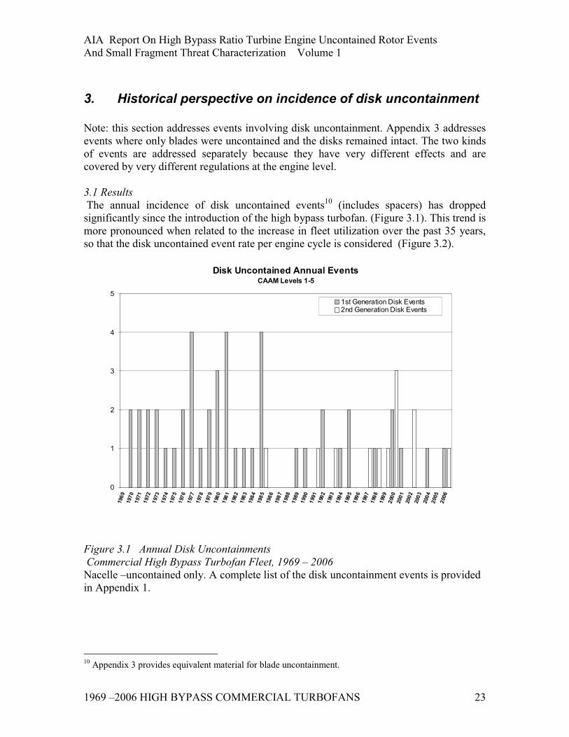
3.1 Results The annual incidence of disk uncontained events10 (includes spacers) has dropped significantly since the introduction of the high bypass turbofan. (Figure 3.1). This trend is more pronounced when related to the increase in fleet utilization over the past 35 years, so that the disk uncontained event rate per engine cycle is considered (Figure 3.2).
Figure 3.1 Annual Disk Uncontainments Commercial High Bypass Turbofan Fleet, 1969 – 2006Nacelle –uncontained only. A complete list of the disk uncontainment events is provided in Appendix 1.
10 Appendix 3 provides equivalent material for blade uncontainment.
Disk Uncontained Annual EventsCAAM Levels 1-5
0
1
2
3
4
5
1969
1970
1971
1972
1973
1974
1975
1976
1977
1978
1979
1980
1981
1982
1983
1984
1985
1986
1987
1988
1989
1990
1991
1992
1993
1994
1995
1996
1997
1998
1999
2000
2001
2002
2003
2004
2005
2006
1st Generation Disk Events2nd Generation Disk Events
AIA Report On High Bypass Ratio Turbine Engine Uncontained Rotor Events And Small Fragment Threat Characterization Volume 1
1969 –2006 HIGH BYPASS COMMERCIAL TURBOFANS 24
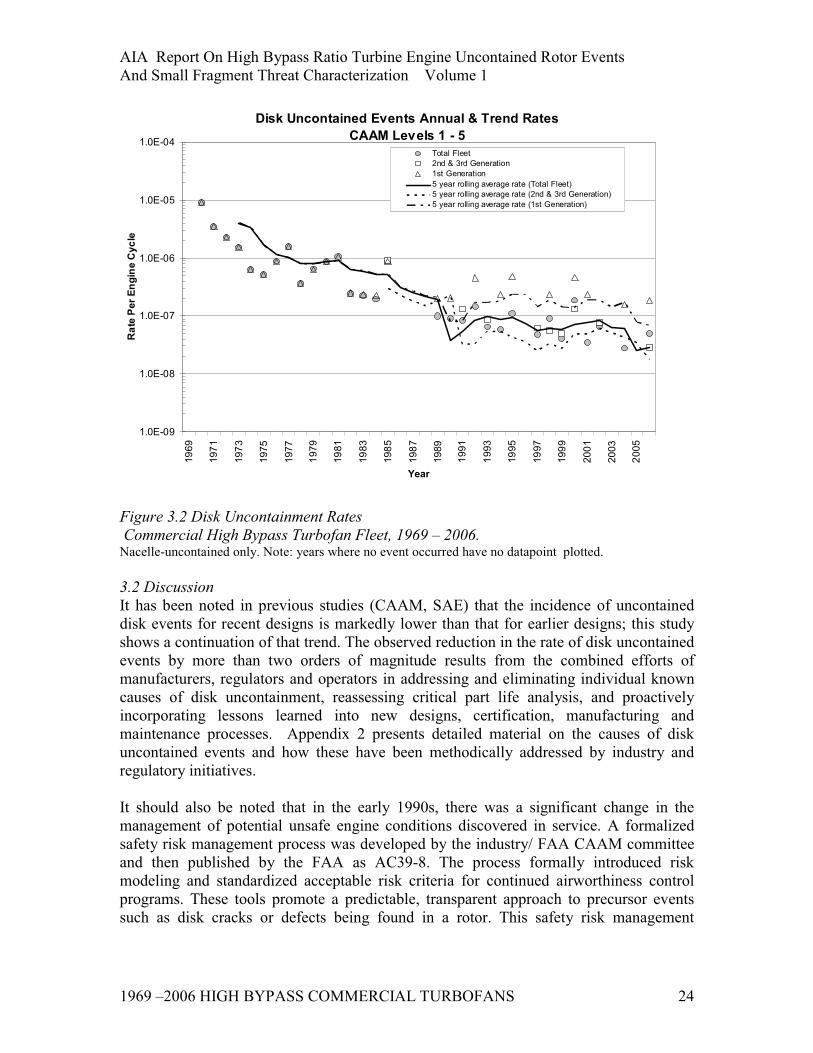
Figure 3.2 Disk Uncontainment Rates Commercial High Bypass Turbofan Fleet, 1969 – 2006. Nacelle-uncontained only. Note: years where no event occurred have no datapoint plotted.
3.2 Discussion It has been noted in previous studies (CAAM, SAE) that the incidence of uncontained disk events for recent designs is markedly lower than that for earlier designs; this study shows a continuation of that trend. The observed reduction in the rate of disk uncontained events by more than two orders of magnitude results from the combined efforts of manufacturers, regulators and operators in addressing and eliminating individual known causes of disk uncontainment, reassessing critical part life analysis, and proactively incorporating lessons learned into new designs, certification, manufacturing and maintenance processes. Appendix 2 presents detailed material on the causes of disk uncontained events and how these have been methodically addressed by industry and regulatory initiatives.
It should also be noted that in the early 1990s, there was a significant change in the management of potential unsafe engine conditions discovered in service. A formalized safety risk management process was developed by the industry/ FAA CAAM committee and then published by the FAA as AC39-8. The process formally introduced risk modeling and standardized acceptable risk criteria for continued airworthiness control programs. These tools promote a predictable, transparent approach to precursor events such as disk cracks or defects being found in a rotor. This safety risk management
Disk Uncontained Events Annual & Trend RatesCAAM Levels 1 - 5
1.0E-09
1.0E-08
1.0E-07
1.0E-06
1.0E-05
1.0E-04
1969
1971
1973
1975
1977
1979
1981
1983
1985
1987
1989
1991
1993
1995
1997
1999
2001
2003
2005
Year
Rat
e P
er E
ngin
e C
ycle
Total Fleet2nd & 3rd Generation1st Generation5 year rolling average rate (Total Fleet)5 year rolling average rate (2nd & 3rd Generation)5 year rolling average rate (1st Generation)
AIA Report On High Bypass Ratio Turbine Engine Uncontained Rotor Events And Small Fragment Threat Characterization Volume 1
1969 –2006 HIGH BYPASS COMMERCIAL TURBOFANS 25
process has benefited not only disk integrity, but other potential safety issues relating to engines or propulsion systems.
As of the end of 2006, the 3rd generation fleet had accumulated 39 million cycles with no disk uncontained events, implying a rate of less than 2.5 E-8/ cycle (rate derived by assuming 1 event occurred). Given the results being achieved by the current fleet, driven by the process improvements described above, it appears likely that the incidence of disk uncontained events for new-design high bypass turbofans will be at least as good as that documented for third generation engines so far.
Although disk uncontained events are rare, and random variation in rates might be expected, Figure 3.2 shows that the annual rates are close to the 5-year rolling average. There is small enough variation from year to year that rates can be compared and firm conclusions drawn from comparison. In particular, occurrence of one more event in the immediate future would not affect the conclusions drawn by this study.
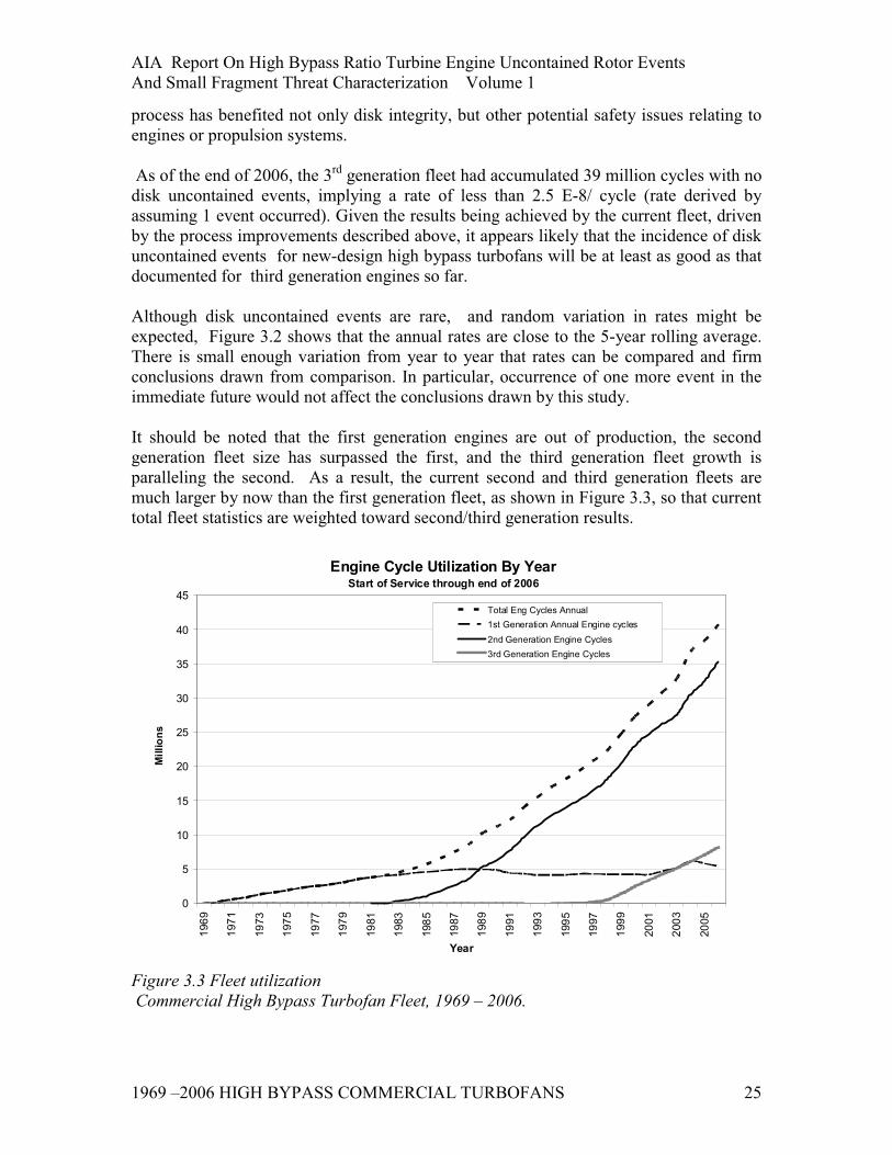
It should be noted that the first generation engines are out of production, the second generation fleet size has surpassed the first, and the third generation fleet growth is paralleling the second. As a result, the current second and third generation fleets are much larger by now than the first generation fleet, as shown in Figure 3.3, so that current total fleet statistics are weighted toward second/third generation results.
Figure 3.3 Fleet utilization Commercial High Bypass Turbofan Fleet, 1969 – 2006.
Engine Cycle Utilization By YearStart of Service through end of 2006
0
5
10
15
20
25
30
35
40
45
1969
1971
1973
1975
1977
1979
1981
1983
1985
1987
1989
1991
1993
1995
1997
1999
2001
2003
2005
Mill
ions
Year
Total Eng Cycles Annual1st Generation Annual Engine cycles2nd Generation Engine Cycles3rd Generation Engine Cycles
AIA Report On High Bypass Ratio Turbine Engine Uncontained Rotor Events And Small Fragment Threat Characterization Volume 1
1969 –2006 HIGH BYPASS COMMERCIAL TURBOFANS 26
3.3 Experience in 2007-2008 In 2007-2008, 2 first-generation disk uncontainments were known to have occurred in 9.3 million engine cycles. No second or third generation disk uncontainment events were identified, in 75.5 million cycles. There may have been other events, but these two events were readily identifiable. A thorough review and update to the report will be issued as an addendum in 2010. These events are consistent with previous experience and do not conflict with the conclusions of this work).

AIA Report On High Bypass Ratio Turbine Engine Uncontained Rotor Events And Small Fragment Threat Characterization Volume 1
1969 –2006 HIGH BYPASS COMMERCIAL TURBOFANS 27
4. Results Section 4.1 summarizes the numbers and rates of disk uncontainments. Section 4.2 addresses the distribution of disk uncontainments by flight phase and by altitude. Section 4.3 addresses the distribution of disk uncontainments by module. Section 4.4 presents data on the rotor speeds at which the disk uncontainments occurred. Section 4.5 reviews the data on fires resulting from disk uncontainment. Section 4.6 presents data on impacts to the airplane by small fragments during a disk burst – the number and kind of impacts, the nature of the structure they impacted and what the results were. Section 4.7 discusses the impacts of large fragments to airplane structure. Section 4.8 addresses systems damage caused by the impact of large and small fragments, with special reference to airplane controllability.Section 4.9 presents data on installation effects. It compares wing and tail installations, and presents data on the effect of stiff or massive structures containing or deflecting large fragments. Section 4.10 presents data on the masses of small fragments retrieved from within the airplane (inside holes made by fragments). Section 4.11 presents and discusses evidence on fragment release speeds – the tangential speed at which the fragments were moving when they exited the engine.
Events involving only blade uncontainment are not analyzed in this section; blade uncontainment results are discussed in appendix 3.
AIA Report On High Bypass Ratio Turbine Engine Uncontained Rotor Events And Small Fragment Threat Characterization Volume 1
1969 –2006 HIGH BYPASS COMMERCIAL TURBOFANS 28
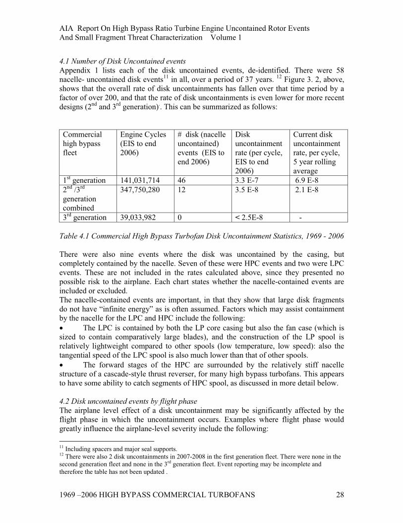
4.1 Number of Disk Uncontained events Appendix 1 lists each of the disk uncontained events, de-identified. There were 58 nacelle- uncontained disk events11 in all, over a period of 37 years. 12 Figure 3. 2, above, shows that the overall rate of disk uncontainments has fallen over that time period by a factor of over 200, and that the rate of disk uncontainments is even lower for more recent designs (2nd and 3rd generation).. This can be summarized as follows:
Commercial high bypass fleet
Engine Cycles (EIS to end 2006)
# disk (nacelle uncontained) events (EIS to end 2006)
Disk uncontainment rate (per cycle, EIS to end 2006)
Current disk uncontainment rate, per cycle, 5 year rolling average
1st generation 141,031,714 46 3.3 E-7 6.9 E-8 2nd /3rd
generation combined
347,750,280 12 3.5 E-8 2.1 E-8
3rd generation 39,033,982 0 < 2.5E-8 -
Table 4.1 Commercial High Bypass Turbofan Disk Uncontainment Statistics, 1969 - 2006
There were also nine events where the disk was uncontained by the casing, but completely contained by the nacelle. Seven of these were HPC events and two were LPC events. These are not included in the rates calculated above, since they presented no possible risk to the airplane. Each chart states whether the nacelle-contained events are included or excluded. The nacelle-contained events are important, in that they show that large disk fragments do not have “infinite energy” as is often assumed. Factors which may assist containment by the nacelle for the LPC and HPC include the following: �� The LPC is contained by both the LP core casing but also the fan case (which is sized to contain comparatively large blades), and the construction of the LP spool is relatively lightweight compared to other spools (low temperature, low speed): also the tangential speed of the LPC spool is also much lower than that of other spools. �� The forward stages of the HPC are surrounded by the relatively stiff nacelle structure of a cascade-style thrust reverser, for many high bypass turbofans. This appears to have some ability to catch segments of HPC spool, as discussed in more detail below.
4.2 Disk uncontained events by flight phase The airplane level effect of a disk uncontainment may be significantly affected by the flight phase in which the uncontainment occurs. Examples where flight phase would greatly influence the airplane-level severity include the following: 11 Including spacers and major seal supports. 12 There were also 2 disk uncontainments in 2007-2008 in the first generation fleet. There were none in the second generation fleet and none in the 3rd generation fleet. Event reporting may be incomplete and therefore the table has not been updated .
AIA Report On High Bypass Ratio Turbine Engine Uncontained Rotor Events And Small Fragment Threat Characterization Volume 1
1969 –2006 HIGH BYPASS COMMERCIAL TURBOFANS 29
�� Cabin pressurization - not an issue below 25,000 ft�� Flight controls - may be less critical on ground �� Thrust loss greater than one engine - long-term thrust capability may be less critical below V1 �� Fuel reserves – not required on the ground �� Fuel containment (fire) – pool fires can not occur in flight
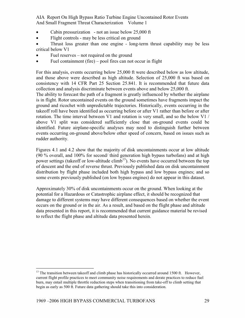
For this analysis, events occurring below 25,000 ft were described below as low altitude, and those above were described as high altitude. Selection of 25,000 ft was based on consistency with 14 CFR Part 25 Section 25.841. It is recommended that future data collection and analysis discriminate between events above and below 25,000 ft. The ability to forecast the path of a fragment is greatly influenced by whether the airplane is in flight. Rotor uncontained events on the ground sometimes have fragments impact the ground and ricochet with unpredictable trajectories. Historically, events occurring in the takeoff roll have been identified as occurring before or after V1 rather than before or after rotation. The time interval between V1 and rotation is very small, and so the below V1 / above V1 split was considered sufficiently close that on-ground events could be identified. Future airplane-specific analyses may need to distinguish further between events occurring on-ground above/below other speed of concern, based on issues such as rudder authority.
Figures 4.1 and 4.2 show that the majority of disk uncontainments occur at low altitude (90 % overall, and 100% for second/ third generation high bypass turbofans) and at high power settings (takeoff or low-altitude climb13). No events have occurred between the top of descent and the end of reverse thrust. Previously published data on disk uncontainment distribution by flight phase included both high bypass and low bypass engines; and so some events previously published (on low bypass engines) do not appear in this dataset.
Approximately 30% of disk uncontainments occur on the ground. When looking at the potential for a Hazardous or Catastrophic airplane effect, it should be recognized that damage to different systems may have different consequences based on whether the event occurs on the ground or in the air. As a result, and based on the flight phase and altitude data presented in this report, it is recommended that current guidance material be revised to reflect the flight phase and altitude data presented herein.
13 The transition between takeoff and climb phase has historically occurred around 1500 ft. However, current flight profile practices to meet community noise requirements and derate practices to reduce fuel burn, may entail multiple throttle reduction steps when transitioning from take-off to climb setting that begin as early as 500 ft. Future data gathering should take this into consideration.

AIA Report On High Bypass Ratio Turbine Engine Uncontained Rotor Events And Small Fragment Threat Characterization Volume 1
1969 –2006 HIGH BYPASS COMMERCIAL TURBOFANS 30
Figure 4.1 Distribution of Disk Uncontainments by Flight Phase Commercial High Bypass Turbofan Fleet, 1969 – 2006Nacelle-uncontained only
Phase of Flight for Disk Uncontained EventsCAAM Levels 1 - 5
14
8
35
54
1
10
6
29
5
21
4
2
6
0
2
00
5
10
15
20
25
30
35
40
-V1 T/O +V1 T/O CLIMB CRUISE MAINTENANCEPREFLIGHT
UNKNOWN
Num
ber o
f Eve
nts
All Gen1st Generation2nd Generation
AIA Report On High Bypass Ratio Turbine Engine Uncontained Rotor Events And Small Fragment Threat Characterization Volume 1
1969 –2006 HIGH BYPASS COMMERCIAL TURBOFANS 31
Figure 4.2 Distribution of Disk Uncontainments by Altitude Commercial High Bypass Turbofan Fleet, 1969 – 2006 Nacelle-uncontained only
Altitude When Disk Uncontained Event OccurredCAAM Levels 1-5
0
5,000
10,000
15,000
20,000
25,000
30,000
35,000
40,000
30% 35% 40% 45% 50% 55% 60% 65% 70% 75% 80% 85% 90% 95% 100%
Percent of Total Events
Alti
tude
1st & 2nd Generation Engines2nd Generation Engines
FAR 25.841 Concern Area > 25,000 feet
AIA Report On High Bypass Ratio Turbine Engine Uncontained Rotor Events And Small Fragment Threat Characterization Volume 1
1969 –2006 HIGH BYPASS COMMERCIAL TURBOFANS 32
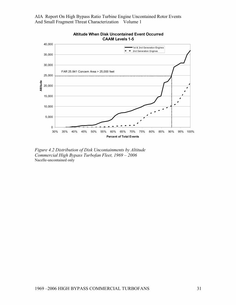
4.3 Disk uncontainments by module Current guidance material is based on an assumption that all rotors are equally likely to experience uncontainment. (Reference 9, section 10 (c ), (e)). In practice, this does not appear to be the case. Figure 4.3 shows the incidence of disk uncontainments by spool. Second generation engines have not experienced any fan, LP/IP compressor or LP turbine disk uncontainments in the 1969 – 2006 study period.
Figure 4.3 Distribution of Disk Uncontainments by Spool Commercial High Bypass Turbofan Fleet, 1969 – 2006
Disk Module/Spool Which Was Nacelle UncontainedCAAM Levels 1 - 5
0%
5%
10%
15%
20%
25%
30%
35%
40%
45%
50%
Fan LPC/IPC HPC HPT LPT/IPT
Module/Spool
Per
cent
age
of T
otal
Total Fleet1st Generation2nd Generation

AIA Report On High Bypass Ratio Turbine Engine Uncontained Rotor Events And Small Fragment Threat Characterization Volume 1
1969 –2006 HIGH BYPASS COMMERCIAL TURBOFANS 33
4.4 Engine speed at disk uncontainment
Figure 4.4 Engine Operating Speed At Time Of Disk Uncontainment Commercial High Bypass Turbofan Fleet, 1969 - 2006
Figure 4.4 shows the rotor speed at the time of disk uncontainment for the 32 of 58 events where rotor speeds were accurately recorded at the time. The data is normalized relative to red line speed for that rotor as documented in the engine type certificate. Current guidance (Ref 8, Paragraph 9 (f)) incorporates the conservative assumption that the uncontained rotor event will occur at red line speed, representing the highest-energy disk fragments. A small number of disk uncontainments (3 events out of 32) have involved rotor overspeed. Overspeed can occur if a turbine disk becomes separated from the rest of the rotor. If the overspeed event is great enough, it may cause the disk to fail. Modern design practices and certification requirements have taken into account the circumstances associated with earlier generation engine overspeed events and should minimize the potential for rotor burst during an overspeed event. The data above supports that disk uncontained events occurring at/above red line rotor speeds is unlikely (less than 10% of disk failures.).14 Based on the uncontained event historical record, recognition that engines are not typically operated at redline, and understanding that current overspeed certification requirements guard against overspeed failures, it is recommended that the AC guidance be reviewed in the context of this chart and of observations on fragment ballistic velocities (below).
14 The majority of uncontained disk events result from a crack in the disk propagating in low cycle fatigue – that is, the typical crack grows whenever the disk is under high stress, when engine speeds are high – and stops growing when stresses are lower (lower engine speeds). There are typically thousands of engine cycles between crack initiation and burst. The disk bursts when the crack reaches critical crack length. Generally, exposure to red line speeds is very infrequent.
Speed at which disk burstNacelle uncontained events only
0
1
2
3
4
5
6
7
8
9
70 orlower
70.1 to75
75.1 to80
80.1 to85
85.1 to90
90.1 to95
95.1 to100
100.1to 105
105.1to 110
110.1to 115
115.1to 120
120.1to 125
125.1to 130
130.1to 135
135.1to 140
140.1to 145
145.1to 150
150.1to 155
% red line speed at burst
# ev
ents
generation 1
generation 2
AIA Report On High Bypass Ratio Turbine Engine Uncontained Rotor Events And Small Fragment Threat Characterization Volume 1
1969 –2006 HIGH BYPASS COMMERCIAL TURBOFANS 34
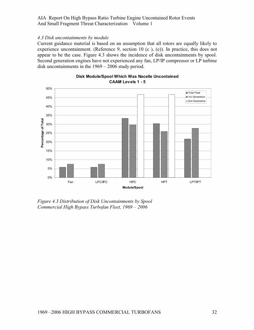
4.5 Fires15 resulting from disk uncontainment The standard hierarchy of design precautions against nacelle fire, including prevention of flammable fluid leakage, fire isolation, fire detection and fire extinguishing, may be compromised as a result of an uncontained disk event. The disk uncontainment event can create undercowl fuel and oil leaks, create ignition sources where none were normally present, disrupt undercowl ventilation flows so that fire detection and extinguishing are potentially disabled, and may breach firewalls intended to isolate the engine fire zones from other zones of the airplane. The potential for a disk uncontainment to result in a severe undercowl fire which could propagate to the airplane is examined in table 4.2 .
18 fires resulting from disk uncontainment
Fuel source Oil in nacelle
3 events
Fuel in nacelle or combined oil and fuel 9 events
Brief Ti fire in engine flowpath, breached case
1 events
Fire location Within nacelle only
13 events
Strut/ Pylon fuel created fire around pylon and wing leading edge (eventually controlled by fuel shutoff)
1 event (level 3)
Fuel from wing tank puncture created pool fire (3 events) Main fuel line in nacelle) ruptured, pooling on ground, eventually controlled by fuel shutoff) 1 event (2 events were level 4, 2 events were level 3)
CAAM level Level 2 (controlled fires) Level 3 or 4 (uncontrolled fires)
Table 4.2 Summary Of Fire Experience Resulting From Disk Uncontained Events Commercial High Bypass Turbofan Fleet, 1969 – 2006
It can be seen from table 4.2 that in practice, fuel or oil leaks within the nacelle (caused by disk uncontainment) create relatively low severity fires which are confined to the nacelle and are controlled by isolating the flammable fluids that could continue to fuel the fire, and do not impinge upon the airplane. These fires do not appear to significantly increase the consequence severity of a disk uncontained event. However, if the disk uncontainment creates a fuel leak from wing tanks, and the airplane is on the ground, the result may be a large pool of fuel with the potential for fire to impinge upon the wing. Details of the fire experience are presented in Appendix 6. None of the fire events in this study has resulted in fatalities, in the study period.
15 Grass fires excluded
AIA Report On High Bypass Ratio Turbine Engine Uncontained Rotor Events And Small Fragment Threat Characterization Volume 1
1969 –2006 HIGH BYPASS COMMERCIAL TURBOFANS 35
The observed hazard ratio for a post-disk uncontainment fire having level 4 effects is 1 in 9; one of the two level 4 events was a non-operational event.
AIA Report On High Bypass Ratio Turbine Engine Uncontained Rotor Events And Small Fragment Threat Characterization Volume 1
1969 –2006 HIGH BYPASS COMMERCIAL TURBOFANS 36
4.6 Small Fragment Impacts To Airplane Structure, from Disk Uncontainment
Over 10,000 witness marks were documented in the course of this work; 680 made holes in the airplane16. About 80 holes were made by large or intermediate fragments; most of the remainder were made by small fragments. In some cases, it was not possible to decide the nature of the fragment involved, and so it was not included in the statistics. The data available varied considerably between events, from brief verbal description to detailed sketches and photographs17. Appendix 5 provides the detailed record of the witness marks left on the airplane by fragment impacts, for each event and for each documented witness mark. Appendix 5 also provides a summary table of the data. Data on airplane damage was not available for all events and therefore some events will not appear in tables and charts; see Appendix 5 table 5.1. The process for determining whether a hole was made by a large, intermediate or small fragment (section 2.3) was based on the size of the hole, the size of surface damage leading to the hole such as scrapes or gouges, any pieces of debris found inside the hole, etc. In a few cases, a hole was made by normally static structure or components which were knocked loose during the disk burst process. These were noted in appendix 5, but not included in statistical analyses18. It should be noted that documenting a hole does not imply that the fragment passed through or would have been able to damage systems inside the hole. This point is discussed further in section 4.6.4.
Data was collected, where available, on the following factors: �� Airplane structure hit by debris (material and thickness, number of layers
fragment passed through) �� Nature of witness mark (paint mark, scratch, dent, closed hole, hole with material
passing through etc, and size of mark)
The orientation of the fragment at the instant of impact was of interest, but it was only possible to establish this for a few out of thousands of impacts, where the fragment was lodged in the hole. There was not enough data for statistical analysis of orientation. The angle of the debris trajectory from the rotor plane, and the angle of the debris trajectory to the airplane target surface were also of interest, but it was not possible to collect this information for most of the events.
16 The data is biased towards conservatism, in that the more damaging impacts are more likely to have been noticed and recorded. Detailed photographs, where available, show many more marks and paint chips than recorded in the investigation notes. It can safely be assumed that those events with minimal documented detail are also likely to have had unrecorded non-damaging witness marks. 17 Since the extent of recorded detail varied widely between events, events were omitted from charts where there was insufficient data to support their incorporation. Summation of holes and cross-checking between charts and from charts to tables will therefore show differences in totals. 18 These “Static structure” pieces were not significant contributors to the overall data. It was not clear how their energies would relate to the more conventional large, intermediate or small fragments. They did not cause damage worse than, or in different locations from, that which might be expected of a large, intermediate or small piece for that event.
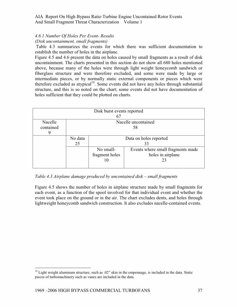
AIA Report On High Bypass Ratio Turbine Engine Uncontained Rotor Events And Small Fragment Threat Characterization Volume 1
1969 –2006 HIGH BYPASS COMMERCIAL TURBOFANS 37
4.6.1 Number Of Holes Per Event- Results (Disk uncontainment, small fragments) Table 4.3 summarizes the events for which there was sufficient documentation to establish the number of holes in the airplane. Figure 4.5 and 4.6 present the data on holes caused by small fragments as a result of disk uncontainment. The charts presented in this section do not show all 680 holes mentioned above, because many of the holes were through light weight honeycomb sandwich or fiberglass structure and were therefore excluded, and some were made by large or intermediate pieces, or by normally static external components or pieces which were therefore excluded as atypical19. Some events did not have any holes through substantial structure, and this is so noted on the chart; some events did not have documentation of holes sufficient that they could be plotted on charts.
Disk burst events reported 67
Nacelle contained
9
Nacelle uncontained 58
No data 25
Data on holes reported 33
No small-fragment holes
10
Events where small fragments made holes in airplane
23
Table 4.3 Airplane damage produced by uncontained disk – small fragments
Figure 4.5 shows the number of holes in airplane structure made by small fragments for each event, as a function of the spool involved for that individual event and whether the event took place on the ground or in the air. The chart excludes dents, and holes through lightweight honeycomb sandwich construction. It also excludes nacelle-contained events.
19 Light weight aluminum structure, such as .02” skin in the empennage, is included in the data. Static pieces of turbomachinery such as vanes are included in the data.

AIA Report On High Bypass Ratio Turbine Engine Uncontained Rotor Events And Small Fragment Threat Characterization Volume 1
1969 –2006 HIGH BYPASS COMMERCIAL TURBOFANS 38
Figure 4.5 Number of holes made by small fragments by spoolEach bar represents one uncontainment event and the height of the bar is the number of holes for that event
Figure 4.6 Number of holes made by small fragments by generation Each bar represents one event.
Figure 4.6 shows the number of holes per event as a function of the state of the art at the time of design (i.e. first vs. second generation high bypass turbofans). First generation engines produced more holes per event than did second generation engines.
Hole count by spool, primary fragmentNacelle-uncontained disk events. Holes made by small fragments beyond the affected nacelle/pylon;
excludes holes through honeycomb sandwich . Data was available for 33 events
0
10
20
30
40
50
60
70
80
90
100
Fan Disk HPC/IPC Disk HPT disk LPT disk HPC rim HPT RimSpool, Primary Fragment
Hol
e co
unt p
er e
vent
3 HPC Disk events with no holes2 HPC rim events with no holes4 HPT rim events with no holes1 LPT rim event with no holes
Air event
Ricochet from ground event
Ground event
Effect of design state-of-the-art on number of holes Nacelle-uncontained disk events. Holes made by small fragments beyond the affected nacelle/pylon;
excludes holes through honeycomb sandwich . Data was available for 33 events
0
10
20
30
40
50
60
70
80
90
100
Generation 1 Generation 2
Hol
e co
unt p
er e
vent
Generation 1: 7 events with no holesGeneration 2: 3 events with no holes
Ricochet from ground event

AIA Report On High Bypass Ratio Turbine Engine Uncontained Rotor Events And Small Fragment Threat Characterization Volume 1
1969 –2006 HIGH BYPASS COMMERCIAL TURBOFANS 39
4.6.2 Number Of Holes Per Event- Discussion (Disk uncontainment, small fragments) It can be seen from figure 4.5 that the number of holes has a skewed distribution; there are many events with a few holes, and a very few events with a large number of holes. In particular, there were three events on the ground which had an unusually large number of holes. Review of the accident investigation reports showed that for these three events, disk pieces had hit the runway surface and generated multiple fragments, which ricocheted up to hit the airplane. This ground ricochet phenomenon could not happen in the air. It is important to discriminate between damage patterns which could occur in the air and those which could only occur on the ground because the airplane-level effect of system damage may have very different severity in the air versus on the ground. The three events where ricochets are known to have contributed toward a significant number of holes are shown in the charts as patterned bars (diagonal stripe). Most disk uncontainments occurring on the ground do not involve ricochets.
Reference 2 reported averages of 6 to 8 holes for a compressor disk uncontainment and 10 – 17 holes for a turbine disk uncontainment, based on 20 high bypass and 19 low bypass events where the disk was nacelle uncontained and made holes in airplane structure. The numbers were calculated as a simple arithmetic average; the sum of the numbers of holes divided by the number of events20. A similar calculation follows, based on the data collected for this high bypass turbofan study21.
Module # events which made holes in airplane
Total holes from holing events
Average holes/holing event
# events where debris struck airplane (hole or dent resulted)
Average holes/ event with debris striking airplane
# nacelle-uncontained events
Average # holes/ nacelle uncontained event
Fan22 1 37 1 37 1 37 LPC - - - - - - - HPC/IPC 7 44 6.3 10 4.4 13 3.4 HPT 9 142 15.8 11 12.9 12 11.8 LPT 6 82 13.7 6 13.7 7 11.7 Table 4.4; Average Number Of Holes Made By Small Fragments (including ricochet events)
20 Since the distribution of number of fragments appears to resemble a geometric distribution, this approach to calculation of an average may not be statistically correct. However, the simple arithmetic average has been retained in tables 4.4 and 4.5 to allow comparison between this report and reference 2. 21 Events where data was not available on hole counts are not included in the denominators. Nacelle-contained events are not included. Holes made by large and intermediate or undetermined fragments or static external structure are not included; holes through honeycomb sandwich construction or fiberglass fairings are not included. 22 Since this is only one event, general conclusions may not be appropriate

AIA Report On High Bypass Ratio Turbine Engine Uncontained Rotor Events And Small Fragment Threat Characterization Volume 1
1969 –2006 HIGH BYPASS COMMERCIAL TURBOFANS 40
Note: Two of the three LPC events were nacelle contained. The number of holes was not recorded for the third LPC event and so no statistics could be developed. Note that debris strikes the airplane in the great majority of nacelle-uncontained events.
The results of table 4.4, using average number of holes per holing event, are broadly similar to those of reference 2. Differences in results may be attributed to the following: �� Table 4.4 uses a dataset confined to high bypass engine disk uncontainments. Reference 2 used a mixture of high bypass and low bypass engines. �� Table 4.4 does not include holes in honeycomb sandwich fairings, whereas reference 1 included all holes. �� The data used for reference 2 was complied in the late 1990s, and therefore included very few second-generation events. First generation engines produced more holes per event than did second generation engines, as seen in Figure 4.6. Table 4.5 shows the difference in statistics if the three ricochet events are not included.
Module # events which made holes in airplane
Total holes from holing events
Average holes/holing event
# events where debris struck airplane (hole or dent resulted)
Average holes/ event with debris striking airplane
# nacelle-uncontained events
Average # holes/ nacelle uncontained event
Fan 1 37 37 1 37 1 37 LPC/IPC - - - - - - - HPC 7 44 6.3 10 4.4 13 3.4 HPT 7 32 4.6 9 3.5 10 3.2 LPT/IPT 5 20 4 5 4 6 3.3 Table 4.5; average number of holes made by small fragments (excluding ricochet events)
Comparison of the reference 2 results with Table 4.5 (average number of holes per holing event) shows greater differences than for Table 4.4. This is because reference 2 did not discriminate between ricochet events and other events. For non-ricochet events, the HPC, HPT and LPT have produced very similar average numbers of holes.
Care is needed in selecting the appropriate “average” when estimating the expected number of holes. If the “average number of holes per holing event” is used, that assumes that the energy of the debris was sufficient to hole the airplane, and excludes disk uncontainments which have released low energy debris. Reference 2, for instance, omitted the events which left no holes in airplane structure and therefore resulted in statistics which were unrepresentative of disk uncontainment experience as a whole. 4.6.3 Effect Of Structure Impacted The airplane is not constructed of uniform skin thickness and materials. Some skins are much more robust than others; for instance, wing skin may be 0.25” aluminum, and empennage skin may be less than one-tenth that thickness. A simple count of the number
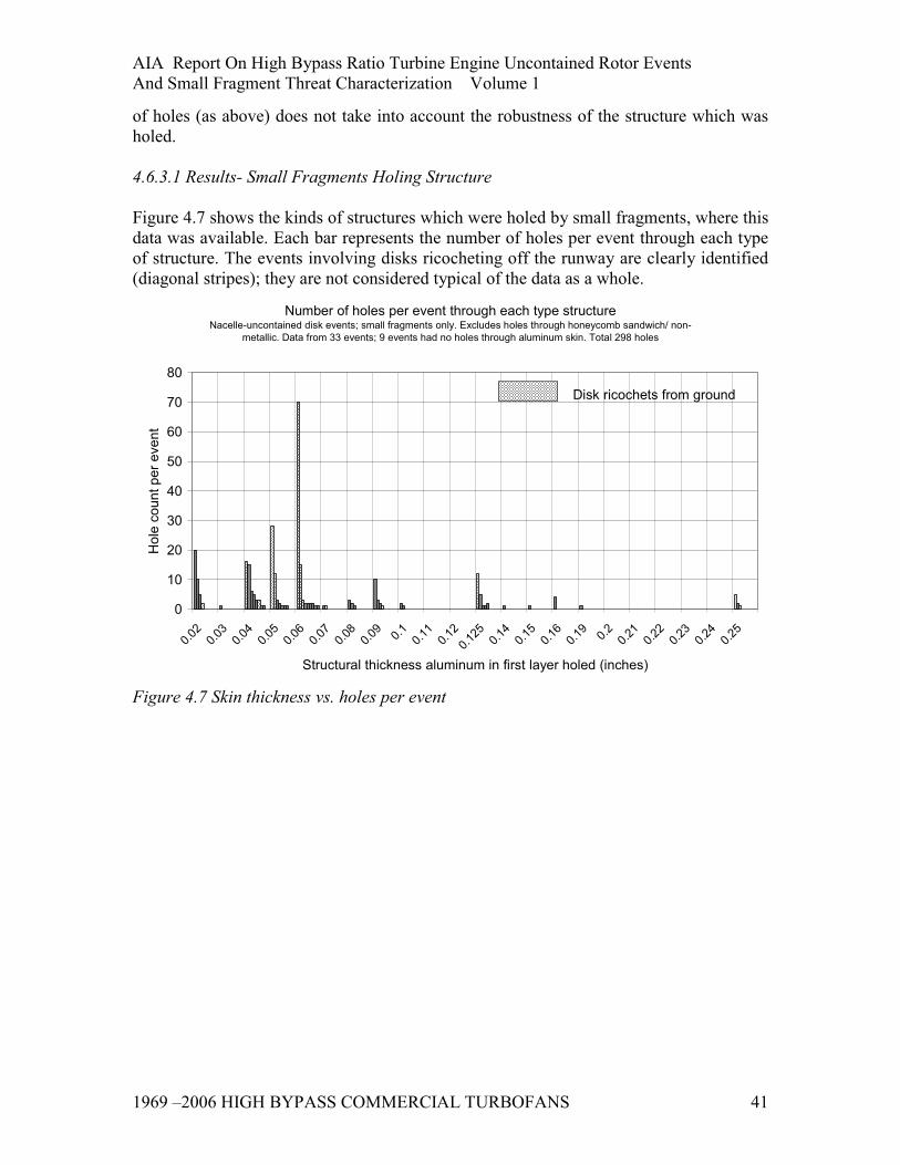
AIA Report On High Bypass Ratio Turbine Engine Uncontained Rotor Events And Small Fragment Threat Characterization Volume 1
1969 –2006 HIGH BYPASS COMMERCIAL TURBOFANS 41
of holes (as above) does not take into account the robustness of the structure which was holed.
4.6.3.1 Results- Small Fragments Holing Structure
Figure 4.7 shows the kinds of structures which were holed by small fragments, where this data was available. Each bar represents the number of holes per event through each type of structure. The events involving disks ricocheting off the runway are clearly identified (diagonal stripes); they are not considered typical of the data as a whole.
Figure 4.7 Skin thickness vs. holes per event
Number of holes per event through each type structureNacelle-uncontained disk events; small fragments only. Excludes holes through honeycomb sandwich/ non-
metallic. Data from 33 events; 9 events had no holes through aluminum skin. Total 298 holes
0
10
20
30
40
50
60
70
80
0.02
0.03
0.04
0.05
0.06
0.07
0.08
0.09 0.1 0.1
10.1
20.1
25 0.14
0.15
0.16
0.19 0.2 0.2
10.2
20.2
30.2
40.2
5
Structural thickness aluminum in first layer holed (inches)
Hol
e co
unt p
er e
vent
Disk ricochets from ground
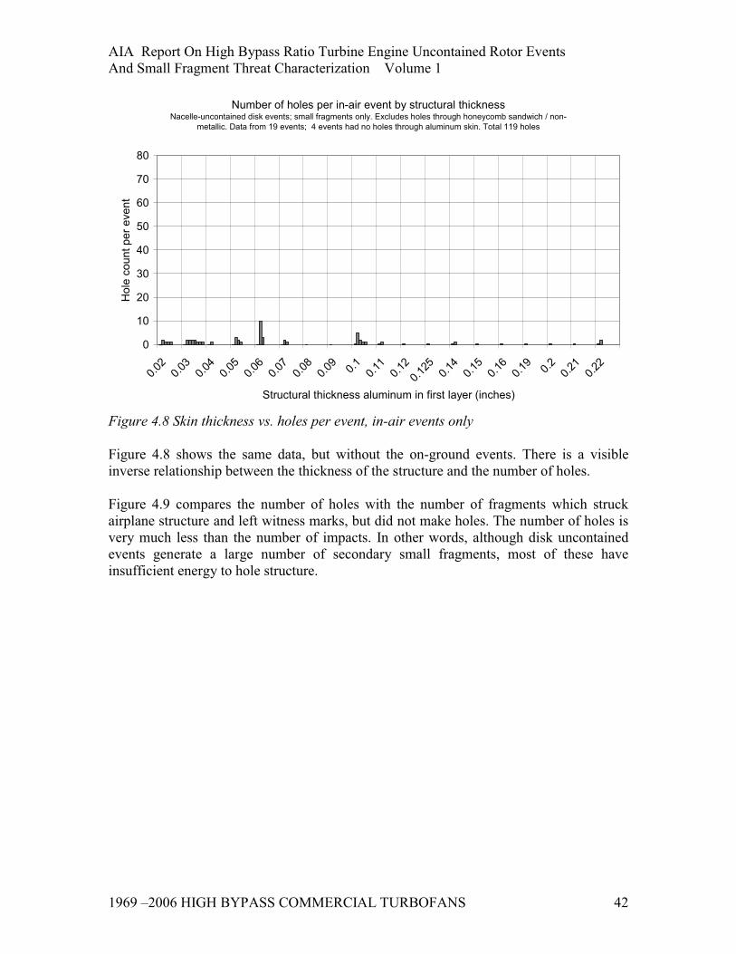
AIA Report On High Bypass Ratio Turbine Engine Uncontained Rotor Events And Small Fragment Threat Characterization Volume 1
1969 –2006 HIGH BYPASS COMMERCIAL TURBOFANS 42
Figure 4.8 Skin thickness vs. holes per event, in-air events only
Figure 4.8 shows the same data, but without the on-ground events. There is a visible inverse relationship between the thickness of the structure and the number of holes.
Figure 4.9 compares the number of holes with the number of fragments which struck airplane structure and left witness marks, but did not make holes. The number of holes is very much less than the number of impacts. In other words, although disk uncontained events generate a large number of secondary small fragments, most of these have insufficient energy to hole structure.
Number of holes per in-air event by structural thickness Nacelle-uncontained disk events; small fragments only. Excludes holes through honeycomb sandwich / non-
metallic. Data from 19 events; 4 events had no holes through aluminum skin. Total 119 holes
0
10
20
30
40
50
60
70
80
0.02
0.03
0.04
0.05
0.06
0.07
0.08
0.09 0.1 0.1
10.1
20.1
25 0.14
0.15
0.16
0.19 0.2 0.2
10.2
2
Structural thickness aluminum in first layer (inches)
Hol
e co
unt p
er e
vent
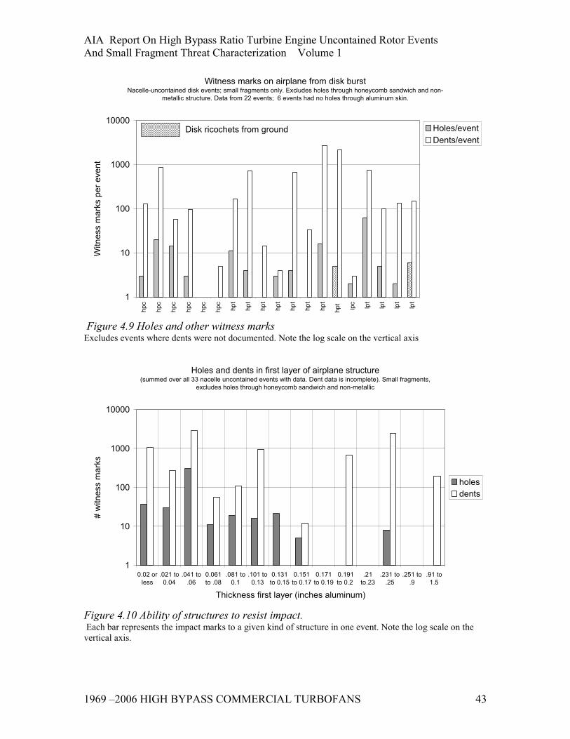
AIA Report On High Bypass Ratio Turbine Engine Uncontained Rotor Events And Small Fragment Threat Characterization Volume 1
1969 –2006 HIGH BYPASS COMMERCIAL TURBOFANS 43
Figure 4.9 Holes and other witness marks Excludes events where dents were not documented. Note the log scale on the vertical axis
Figure 4.10 Ability of structures to resist impact. Each bar represents the impact marks to a given kind of structure in one event. Note the log scale on the vertical axis.
Holes and dents in first layer of airplane structure (summed over all 33 nacelle uncontained events with data. Dent data is incomplete). Small fragments,
excludes holes through honeycomb sandwich and non-metallic
1
10
100
1000
10000
0.02 orless
.021 to0.04
.041 to.06
0.061to .08
.081 to0.1
.101 to0.13
0.131to 0.15
0.151to 0.17
0.171to 0.19
0.191to 0.2
.21to.23
.231 to.25
.251 to.9
.91 to1.5
Thickness first layer (inches aluminum)
# w
itnes
s m
arks
holesdents
Witness marks on airplane from disk burst Nacelle-uncontained disk events; small fragments only. Excludes holes through honeycomb sandwich and non-
metallic structure. Data from 22 events; 6 events had no holes through aluminum skin.
1
10
100
1000
10000
hpc
hpc
hpc
hpc
hpc
hpc
hpt
hpt
hpt
hpt
hpt
hpt
hpt
hpt
ipc lpt
lpt
lpt
lpt
Witn
ess
mar
ks p
er e
vent
Holes/eventDents/event
Disk ricochets from ground
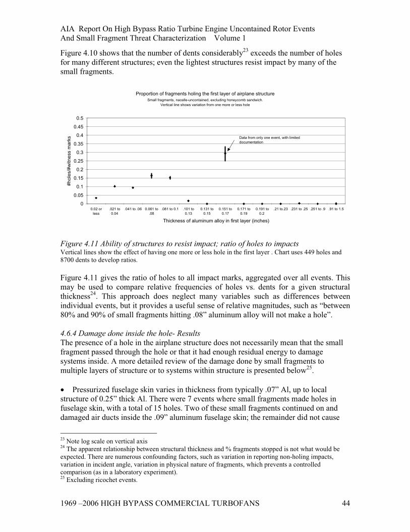
AIA Report On High Bypass Ratio Turbine Engine Uncontained Rotor Events And Small Fragment Threat Characterization Volume 1
1969 –2006 HIGH BYPASS COMMERCIAL TURBOFANS 44
Figure 4.10 shows that the number of dents considerably23 exceeds the number of holes for many different structures; even the lightest structures resist impact by many of the small fragments.
Figure 4.11 Ability of structures to resist impact; ratio of holes to impacts Vertical lines show the effect of having one more or less hole in the first layer . Chart uses 449 holes and 8700 dents to develop ratios.
Figure 4.11 gives the ratio of holes to all impact marks, aggregated over all events. This may be used to compare relative frequencies of holes vs. dents for a given structural thickness24. This approach does neglect many variables such as differences between individual events, but it provides a useful sense of relative magnitudes, such as “between 80% and 90% of small fragments hitting .08” aluminum alloy will not make a hole”.
4.6.4 Damage done inside the hole- Results The presence of a hole in the airplane structure does not necessarily mean that the small fragment passed through the hole or that it had enough residual energy to damage systems inside. A more detailed review of the damage done by small fragments to multiple layers of structure or to systems within structure is presented below25.
�� Pressurized fuselage skin varies in thickness from typically .07” Al, up to local structure of 0.25” thick Al. There were 7 events where small fragments made holes in fuselage skin, with a total of 15 holes. Two of these small fragments continued on and damaged air ducts inside the .09” aluminum fuselage skin; the remainder did not cause
23 Note log scale on vertical axis 24 The apparent relationship between structural thickness and % fragments stopped is not what would be expected. There are numerous confounding factors, such as variation in reporting non-holing impacts, variation in incident angle, variation in physical nature of fragments, which prevents a controlled comparison (as in a laboratory experiment). 25 Excluding ricochet events.
Proportion of fragments holing the first layer of airplane structureSmall fragments, nacelle-uncontained, excluding honeycomb sandwich.
Vertical line shows variation from one more or less hole
0
0.05
0.1
0.15
0.2
0.25
0.3
0.35
0.4
0.45
0.5
0.02 orless
.021 to0.04
.041 to .06 0.061 to.08
.081 to 0.1 .101 to0.13
0.131 to0.15
0.151 to0.17
0.171 to0.19
0.191 to0.2
.21 to.23 .231 to .25 .251 to .9 .91 to 1.5
Thickness of aluminum alloy in first layer (inches)
#hol
es/#
witn
ess
mar
ks Data from only one event, with limited documentation
AIA Report On High Bypass Ratio Turbine Engine Uncontained Rotor Events And Small Fragment Threat Characterization Volume 1
1969 –2006 HIGH BYPASS COMMERCIAL TURBOFANS 45
any damage to systems or structure inside the skin. One of the two fragments passed through both walls of the air duct, dented the wall of a second air duct and lodged against a honeycomb sandwich cabin floor. The other fragment passed through only one wall of the air duct. The construction of the air ducts is not recorded. �� Wing skin is typically 0.125 aluminum; thicknesses can be up to 0.25 inboard of the engine. There was one event in which small fragments made 2 holes in a single layer of wing skin. No small fragments are recorded as holing wing skin and then doing further damage. �� Access doors and panels are typically .08” aluminum. There were six events in which small fragments made holes in access panels and doors, with a total of 13 holes. In one event, a fragment passed through the .06” aluminum panel skin and damaged the reinforcing web inside. �� The wing leading edge – aft of the slats or flaps, but forward of the front spar – is typically 0.1” thick aluminum. There were seven events recorded where small fragments made holes in the wing leading edge, with a total of 24 holes. In one of these events, a small fragment continued up to make exit hole through the top of the leading edge (.09” aluminum). �� The wing leading edge and trailing edge control surfaces are typically of light construction such as .04” aluminum. There were 6 events where small fragments made holes in these surfaces, for a total of seven holes. In one case, a fragment made a hole through a 0.125” thick surface and then continued on to pass through an equivalent thickness upper surface. �� The empennage is typically .02” thick aluminum skin, riveted to .02” thick doublers. There were five events in which small fragments holed the empennage skin, with a total of 63 holes. Twelve of these fragments had sufficient residual energy to pass completely through the empennage – through a second layer of .02 to .04 aluminum. In two cases the fragment also dented and bent ¾” diameter stainless steel hydraulic lines in transit .
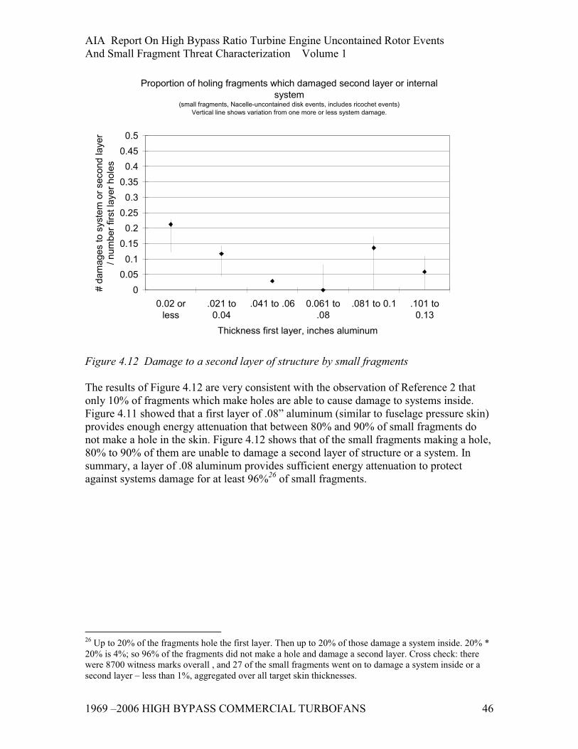
AIA Report On High Bypass Ratio Turbine Engine Uncontained Rotor Events And Small Fragment Threat Characterization Volume 1
1969 –2006 HIGH BYPASS COMMERCIAL TURBOFANS 46
Figure 4.12 Damage to a second layer of structure by small fragments
The results of Figure 4.12 are very consistent with the observation of Reference 2 that only 10% of fragments which make holes are able to cause damage to systems inside. Figure 4.11 showed that a first layer of .08” aluminum (similar to fuselage pressure skin) provides enough energy attenuation that between 80% and 90% of small fragments do not make a hole in the skin. Figure 4.12 shows that of the small fragments making a hole, 80% to 90% of them are unable to damage a second layer of structure or a system. In summary, a layer of .08 aluminum provides sufficient energy attenuation to protect against systems damage for at least 96%26 of small fragments.
26 Up to 20% of the fragments hole the first layer. Then up to 20% of those damage a system inside. 20% * 20% is 4%; so 96% of the fragments did not make a hole and damage a second layer. Cross check: there were 8700 witness marks overall , and 27 of the small fragments went on to damage a system inside or a second layer – less than 1%, aggregated over all target skin thicknesses.
Proportion of holing fragments which damaged second layer or internal system
(small fragments, Nacelle-uncontained disk events, includes ricochet events) Vertical line shows variation from one more or less system damage.
00.050.1
0.150.2
0.250.3
0.350.4
0.450.5
0.02 orless
.021 to0.04
.041 to .06 0.061 to.08
.081 to 0.1 .101 to0.13
Thickness first layer, inches aluminum
# da
mag
es to
sys
tem
or s
econ
d la
yer
/ num
ber f
irst l
ayer
hol
es

AIA Report On High Bypass Ratio Turbine Engine Uncontained Rotor Events And Small Fragment Threat Characterization Volume 1
1969 –2006 HIGH BYPASS COMMERCIAL TURBOFANS 47
4.7 Large Fragment Impacts To Airplane Structure, from Disk Uncontainment
There were a number of events where large disk pieces hit heavy airplane structure and were either stopped or deflected. Wing skin, and the wing fixed leading edge and associated cables and ducts, appeared to have some appreciable ability to stop or deflect large disk pieces, so that it effectively shielded the fuselage in many cases. Table 4.6 presents the available data on impacts to the wing by large and intermediate fragments, and the results (the events are ranked by severity of the result).
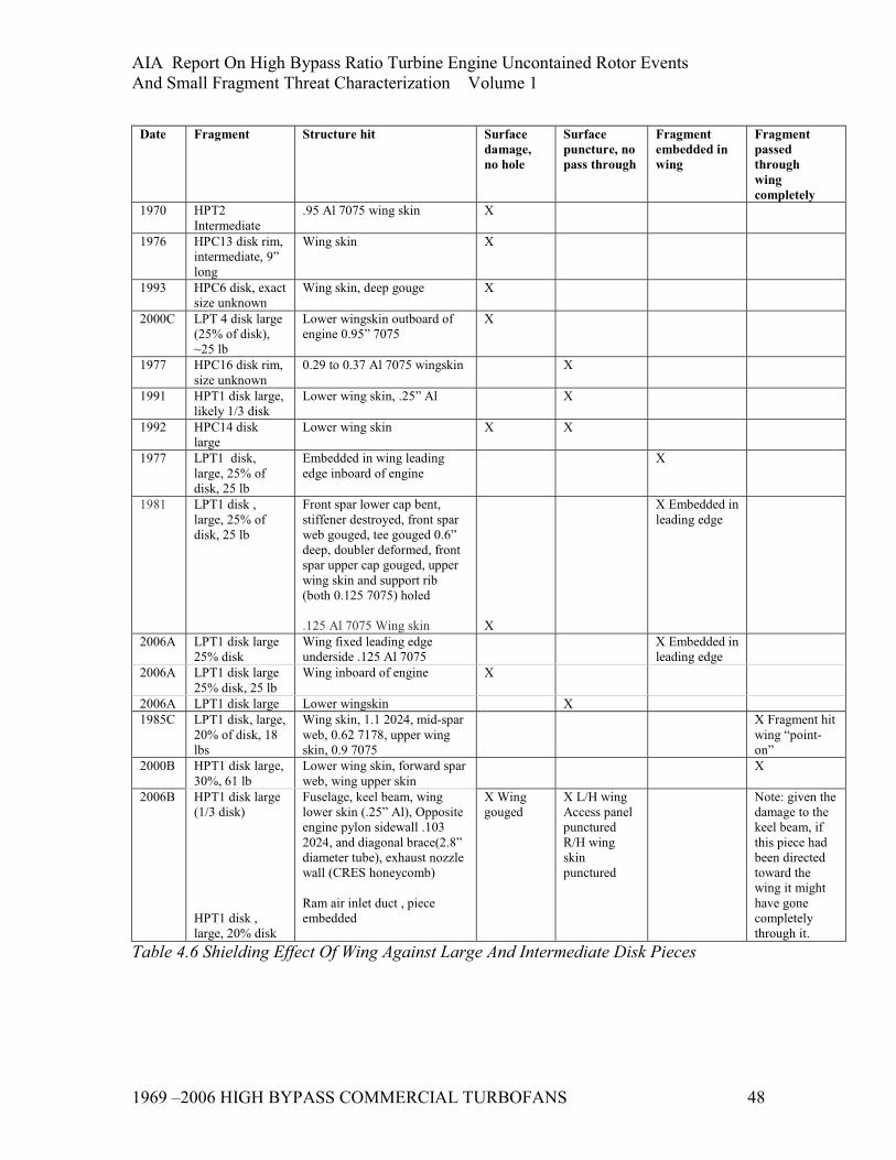
AIA Report On High Bypass Ratio Turbine Engine Uncontained Rotor Events And Small Fragment Threat Characterization Volume 1
1969 –2006 HIGH BYPASS COMMERCIAL TURBOFANS 48
Date Fragment Structure hit Surface damage, no hole
Surface puncture, no pass through
Fragment embedded in wing
Fragment passed through wing completely
1970 HPT2 Intermediate
.95 Al 7075 wing skin X
1976 HPC13 disk rim, intermediate, 9” long
Wing skin X
1993 HPC6 disk, exact size unknown
Wing skin, deep gouge X
2000C LPT 4 disk large (25% of disk), ~25 lb
Lower wingskin outboard of engine 0.95” 7075
X
1977 HPC16 disk rim, size unknown
0.29 to 0.37 Al 7075 wingskin X
1991 HPT1 disk large, likely 1/3 disk
Lower wing skin, .25” Al X
1992 HPC14 disk large
Lower wing skin X X
1977 LPT1 disk, large, 25% of disk, 25 lb
Embedded in wing leading edge inboard of engine
X
1981 LPT1 disk , large, 25% of disk, 25 lb
Front spar lower cap bent, stiffener destroyed, front spar web gouged, tee gouged 0.6” deep, doubler deformed, front spar upper cap gouged, upper wing skin and support rib (both 0.125 7075) holed
.125 Al 7075 Wing skin X
X Embedded in leading edge
2006A LPT1 disk large 25% disk
Wing fixed leading edge underside .125 Al 7075
X Embedded in leading edge
2006A LPT1 disk large 25% disk, 25 lb
Wing inboard of engine X
2006A LPT1 disk large Lower wingskin X 1985C LPT1 disk, large,
20% of disk, 18 lbs
Wing skin, 1.1 2024, mid-spar web, 0.62 7178, upper wing skin, 0.9 7075
X Fragment hit wing “point-on”
2000B HPT1 disk large, 30%, 61 lb
Lower wing skin, forward spar web, wing upper skin
X
2006B HPT1 disk large (1/3 disk)
HPT1 disk , large, 20% disk
Fuselage, keel beam, wing lower skin (.25” Al), Opposite engine pylon sidewall .103 2024, and diagonal brace(2.8” diameter tube), exhaust nozzle wall (CRES honeycomb)
Ram air inlet duct , piece embedded
X Wing gouged
X L/H wing Access panel punctured R/H wing skin punctured
Note: given the damage to the keel beam, if this piece had been directed toward the wing it might have gone completely through it.
Table 4.6 Shielding Effect Of Wing Against Large And Intermediate Disk Pieces
AIA Report On High Bypass Ratio Turbine Engine Uncontained Rotor Events And Small Fragment Threat Characterization Volume 1
1969 –2006 HIGH BYPASS COMMERCIAL TURBOFANS 49
4.8 Damage to airplane systems
Table 4.7 summarizes the events where fragments damaged unrelated systems, to the extent that airplane controllability was immediately reduced, or would have been, had the airplane been airborne at the time. Damage to systems which did not affect the ability of the airplane to sustain short-term controlled flight (e.g. damage to ECS systems; damage to a second engine which did not affect thrust; fuel leaks) is not included in the table. Figure 4.13 shows photographs and sketches of the location of the system damage with respect to the failed engine.
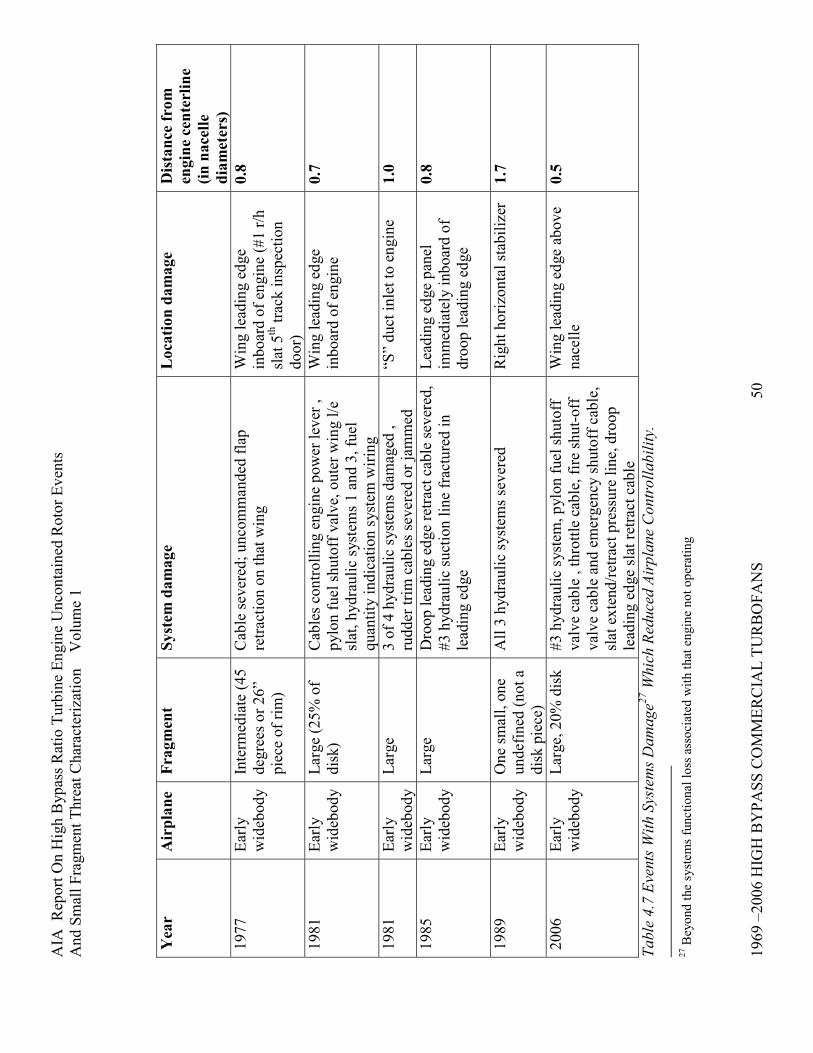
AIA
Rep
ort O
n H
igh
Byp
ass R
atio
Tur
bine
Eng
ine
Unc
onta
ined
Rot
or E
vent
s A
nd S
mal
l Fra
gmen
t Thr
eat C
hara
cter
izat
ion
V
olum
e 1
1969
–20
06 H
IGH
BY
PASS
CO
MM
ERC
IAL
TUR
BO
FAN
S 50
Yea
r
Air
plan
e Fr
agm
ent
Syst
em d
amag
e L
ocat
ion
dam
age
Dis
tanc
e fr
om
engi
ne c
ente
rlin
e (in
nac
elle
di
amet
ers)
19
77
Early
w
ideb
ody
Inte
rmed
iate
(45
degr
ees o
r 26”
pi
ece
of ri
m)
Cab
le se
vere
d; u
ncom
man
ded
flap
retra
ctio
n on
that
win
g W
ing
lead
ing
edge
in
boar
d of
eng
ine
(#1
r/h
slat
5th
trac
k in
spec
tion
door
)
0.8
1981
Ea
rly
wid
ebod
yLa
rge
(25%
of
disk
) C
able
s con
trolli
ng e
ngin
e po
wer
leve
r ,
pylo
n fu
el sh
utof
f val
ve, o
uter
win
g l/e
sl
at, h
ydra
ulic
syst
ems 1
and
3, f
uel
quan
tity
indi
catio
n sy
stem
wiri
ng
Win
g le
adin
g ed
ge
inbo
ard
of e
ngin
e 0.
7
1981
Ea
rly
wid
ebod
yLa
rge
3 of
4 h
ydra
ulic
sys
tem
s dam
aged
, ru
dder
trim
cab
les s
ever
ed o
r jam
med
“S
” du
ct in
let t
o en
gine
1.
0
1985
Ea
rly
wid
ebod
yLa
rge
Dro
op le
adin
g ed
ge re
tract
cab
le se
vere
d,
#3 h
ydra
ulic
suct
ion
line
frac
ture
d in
le
adin
g ed
ge
Lead
ing
edge
pan
el
imm
edia
tely
inbo
ard
of
droo
p le
adin
g ed
ge
0.8
1989
Ea
rly
wid
ebod
yO
ne sm
all,
one
unde
fined
(not
a
disk
pie
ce)
All
3 hy
drau
lic sy
stem
s sev
ered
R
ight
hor
izon
tal s
tabi
lizer
1.
7
2006
Ea
rly
wid
ebod
yLa
rge,
20%
dis
k #3
hyd
raul
ic s
yste
m, p
ylon
fuel
shut
off
valv
e ca
ble
, thr
ottle
cab
le, f
ire sh
ut-o
ff
valv
e ca
ble
and
emer
genc
y sh
utof
f cab
le,
slat
ext
end/
retra
ct p
ress
ure
line,
dro
op
lead
ing
edge
slat
retra
ct c
able
Win
g le
adin
g ed
ge a
bove
na
celle
0.
5
Tabl
e 4.
7 Ev
ents
With
Sys
tem
s Dam
age27
Whi
ch R
educ
ed A
irpl
ane
Con
trol
labi
lity.
27
Bey
ond
the
syst
ems f
unct
iona
l los
s ass
ocia
ted
with
that
eng
ine
not o
pera
ting

AIA Report On High Bypass Ratio Turbine Engine Uncontained Rotor Events And Small Fragment Threat Characterization Volume 1
1969 –2006 HIGH BYPASS COMMERCIAL TURBOFANS 51
Figure 4.13 Examples of events where disk burst resulted in systems damage which reduced airplane controllability
Engine
1981 2006
1977 1985
AIA Report On High Bypass Ratio Turbine Engine Uncontained Rotor Events And Small Fragment Threat Characterization Volume 1
1969 –2006 HIGH BYPASS COMMERCIAL TURBOFANS 52
4.8.1. Systems Damage- Results Six events were identified where the disk uncontainment resulted in damage to airplane systems (beyond the affected engine) which would affect airplane controllability. All of these events occurred on early-design widebody airplanes28. In the case of the four wing-installed engines, the systems damage was always in the wing leading edge, immediately inboard of the affected engine (within one nacelle diameter of the affected engine centerline.) In each case, there was damage to the controls for one or more leading edge slats, and the damage was caused by a large piece of disk. In the remaining events, on tail installed engines, there was damage to multiple hydraulic lines adjacent to the affected engine, within 2 nacelle diameters of the affected engine centerline. In one case the damage was caused by a small fragment and an undetermined fragment (likely of intermediate size). In the other case details were not available.
4.8.2 Systems Damage - Discussion The results above illustrate that the greatest likelihood of systems damage is where systems are closely grouped, in the plane of the disk, within one or two nacelle diameters of the engine centerline. In each case, either the damaging fragment was large (e.g. 20% of the disk) or the intervening structure was lightweight (.02” to .04” Al.)
28 Designed before publication of AC 20-128.
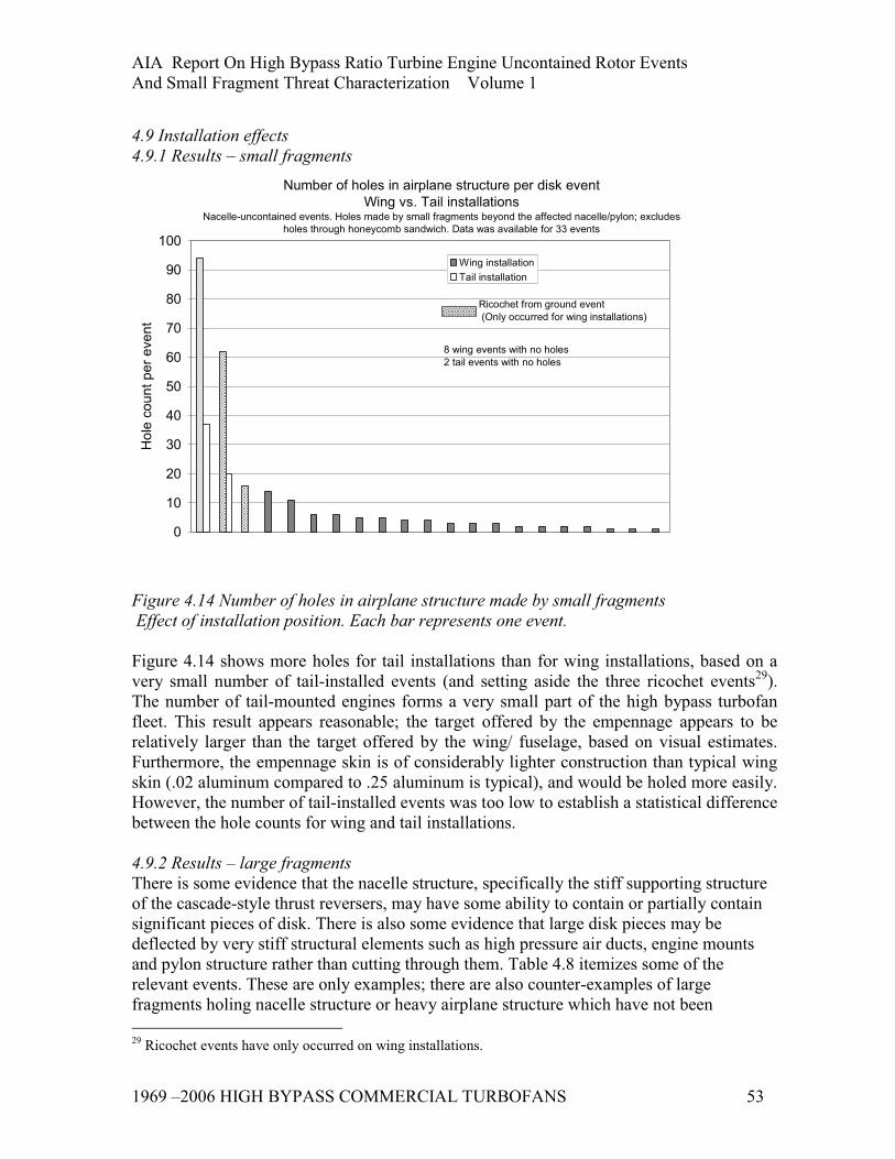
AIA Report On High Bypass Ratio Turbine Engine Uncontained Rotor Events And Small Fragment Threat Characterization Volume 1
1969 –2006 HIGH BYPASS COMMERCIAL TURBOFANS 53
4.9 Installation effects 4.9.1 Results – small fragments
Figure 4.14 Number of holes in airplane structure made by small fragments Effect of installation position. Each bar represents one event.
Figure 4.14 shows more holes for tail installations than for wing installations, based on a very small number of tail-installed events (and setting aside the three ricochet events29). The number of tail-mounted engines forms a very small part of the high bypass turbofan fleet. This result appears reasonable; the target offered by the empennage appears to be relatively larger than the target offered by the wing/ fuselage, based on visual estimates. Furthermore, the empennage skin is of considerably lighter construction than typical wing skin (.02 aluminum compared to .25 aluminum is typical), and would be holed more easily. However, the number of tail-installed events was too low to establish a statistical difference between the hole counts for wing and tail installations.
4.9.2 Results – large fragments There is some evidence that the nacelle structure, specifically the stiff supporting structure of the cascade-style thrust reversers, may have some ability to contain or partially contain significant pieces of disk. There is also some evidence that large disk pieces may be deflected by very stiff structural elements such as high pressure air ducts, engine mounts and pylon structure rather than cutting through them. Table 4.8 itemizes some of the relevant events. These are only examples; there are also counter-examples of large fragments holing nacelle structure or heavy airplane structure which have not been 29 Ricochet events have only occurred on wing installations.
Number of holes in airplane structure per disk event Wing vs. Tail installations
Nacelle-uncontained events. Holes made by small fragments beyond the affected nacelle/pylon; excludes holes through honeycomb sandwich. Data was available for 33 events
0
10
20
30
40
50
60
70
80
90
100
Hol
e co
unt p
er e
vent
Wing installationTail installation
8 wing events with no holes2 tail events with no holes
Ricochet from ground event (Only occurred for wing installations)
AIA Report On High Bypass Ratio Turbine Engine Uncontained Rotor Events And Small Fragment Threat Characterization Volume 1
1969 –2006 HIGH BYPASS COMMERCIAL TURBOFANS 54
tabulated here. The results show an opportunity for further investigation, rather than any firm conclusion that large fragments will always, or will never, be deflected or contained.
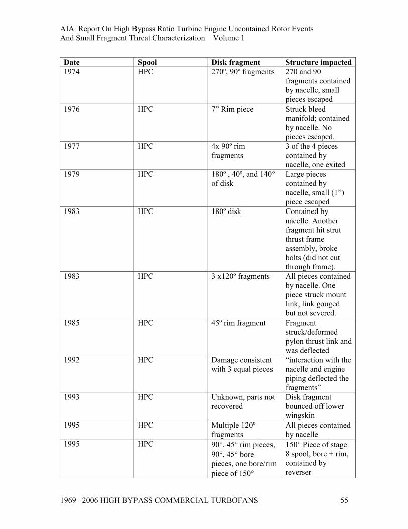
AIA Report On High Bypass Ratio Turbine Engine Uncontained Rotor Events And Small Fragment Threat Characterization Volume 1
1969 –2006 HIGH BYPASS COMMERCIAL TURBOFANS 55
Date Spool Disk fragment Structure impacted1974 HPC 270º, 90º fragments 270 and 90
fragments contained by nacelle, small pieces escaped
1976 HPC 7” Rim piece Struck bleed manifold; contained by nacelle. No pieces escaped.
1977 HPC 4x 90º rim fragments
3 of the 4 pieces contained by nacelle, one exited
1979 HPC 180º , 40º, and 140º of disk
Large pieces contained by nacelle, small (1”) piece escaped
1983 HPC 180º disk Contained by nacelle. Another fragment hit strut thrust frame assembly, broke bolts (did not cut through frame).
1983 HPC 3 x120º fragments All pieces contained by nacelle. One piece struck mount link, link gouged but not severed.
1985 HPC 45º rim fragment Fragment struck/deformed pylon thrust link and was deflected
1992 HPC Damage consistent with 3 equal pieces
“interaction with the nacelle and engine piping deflected the fragments”
1993 HPC Unknown, parts not recovered
Disk fragment bounced off lower wingskin
1995 HPC Multiple 120º fragments
All pieces contained by nacelle
1995 HPC 90�, 45� rim pieces, 90�, 45� bore pieces, one bore/rim piece of 150�
150� Piece of stage 8 spool, bore + rim, contained by reverser
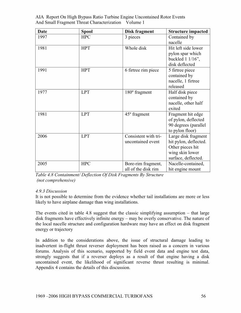
AIA Report On High Bypass Ratio Turbine Engine Uncontained Rotor Events And Small Fragment Threat Characterization Volume 1
1969 –2006 HIGH BYPASS COMMERCIAL TURBOFANS 56
Date Spool Disk fragment Structure impacted1997 HPC 3 pieces Contained by
nacelle 1981 HPT Whole disk Hit left side lower
pylon spar which buckled 1 1/16”, disk deflected
1991 HPT 6 firtree rim piece 5 firtree piece contained by nacelle, 1 firtree released
1977 LPT 180º fragment Half disk piece contained by nacelle, other half exited
1981 LPT 45º fragment Fragment hit edge of pylon, deflected 90 degrees (parallel to pylon floor)
2006 LPT Consistent with tri-uncontained event
Large disk fragment hit pylon, deflected. Other pieces hit wing skin lower surface, deflected.
2005 HPC Bore-rim fragment, all of the disk rim
Nacelle-contained, hit engine mount
Table 4.8 Containment/ Deflection Of Disk Fragments By Structure (not comprehensive)
4.9.3 Discussion It is not possible to determine from the evidence whether tail installations are more or less likely to have airplane damage than wing installations.
The events cited in table 4.8 suggest that the classic simplifying assumption – that large disk fragments have effectively infinite energy – may be overly conservative. The nature of the local nacelle structure and configuration hardware may have an effect on disk fragment energy or trajectory
In addition to the considerations above, the issue of structural damage leading to inadvertent in-flight thrust reverser deployment has been raised as a concern in various forums. Analysis of this scenario, supported by field event data and engine test data, strongly suggests that if a reverser deploys as a result of that engine having a disk uncontained event, the likelihood of significant reverse thrust resulting is minimal. Appendix 4 contains the details of this discussion.

AIA Report On High Bypass Ratio Turbine Engine Uncontained Rotor Events And Small Fragment Threat Characterization Volume 1
1969 –2006 HIGH BYPASS COMMERCIAL TURBOFANS 57
The issue of an engine departing the airplane as a result of disk uncontainment has also been raised as a concern. This could occur as a result of high unbalance loads or as a result of a disk fragment striking the engine mounts or the pylon. Table 4.8 gives some instances of a large or intermediate fragment being deflected by a mount link or by the pylon, but there is no guarantee that this would happen in every case; the mount link or the pylon might be damaged so that the engine could depart the airplane. The airplane-level effects of the engine departing the airplane are greatly influenced by whether the engine is producing thrust at the moment of separation, for high bypass turbofans. Events (unrelated to disk uncontainment) where the pylon failed, and the engine departed under thrust, have historically included damage to the wing leading edge and difficulty with airplane control. An event where the engine departed after a disk uncontainment was more benign, and the engine dropped away from the wing with relatively little secondary damage.
4.10 Small Fragment Masses Small fragments were retrieved from inside the airplane for a limited number of uncontained rotor events. The debris from these seven events included disk fragments, blade fragments and ancillary hardware. Most events did not have fragments retrieved from inside the holes. The masses of these small fragments, where available, are summarized in figure 4.15 and figure 4.16; a detailed account of each collected fragment is provided in appendix 9. Debris collected from the ground was not used for this assessment since the paths taken by those fragments could not be established, and it was not clear whether pieces hit the airplane and bounced off, were released in directions which would not hit the airplane, or had insufficient initial energy to hit the airplane and fell out through the hole in the cowling. Using the fragments collected from inside the airplane ensured that the fragments were relatively high-energy (since they were able to make holes in structure).
4.10.1 Small Fragment Masses - Results Figure 4.15 shows the absolute mass of the fragment retrieved from inside the airplane, each bar representing one fragment. Figure 4.16 shows the fragment as a percentage of a blade airfoil (relating the data to the guidance given in AC 20-128A, which advises that a small fragment be modeled as the outer half of a blade airfoil, or in the case of a fan blade, the outer 1/3 of the airfoil.) For both charts, the fragments collected after events involving disk ricochet are shaded with a diagonal stripe, and the fragments which accompanied a large disk piece into the airplane structure – in other words, the large piece made the hole, and small pieces were retrieved from inside the hole – are shaded black, so that they can be distinguished from the remaining data (shaded grey).
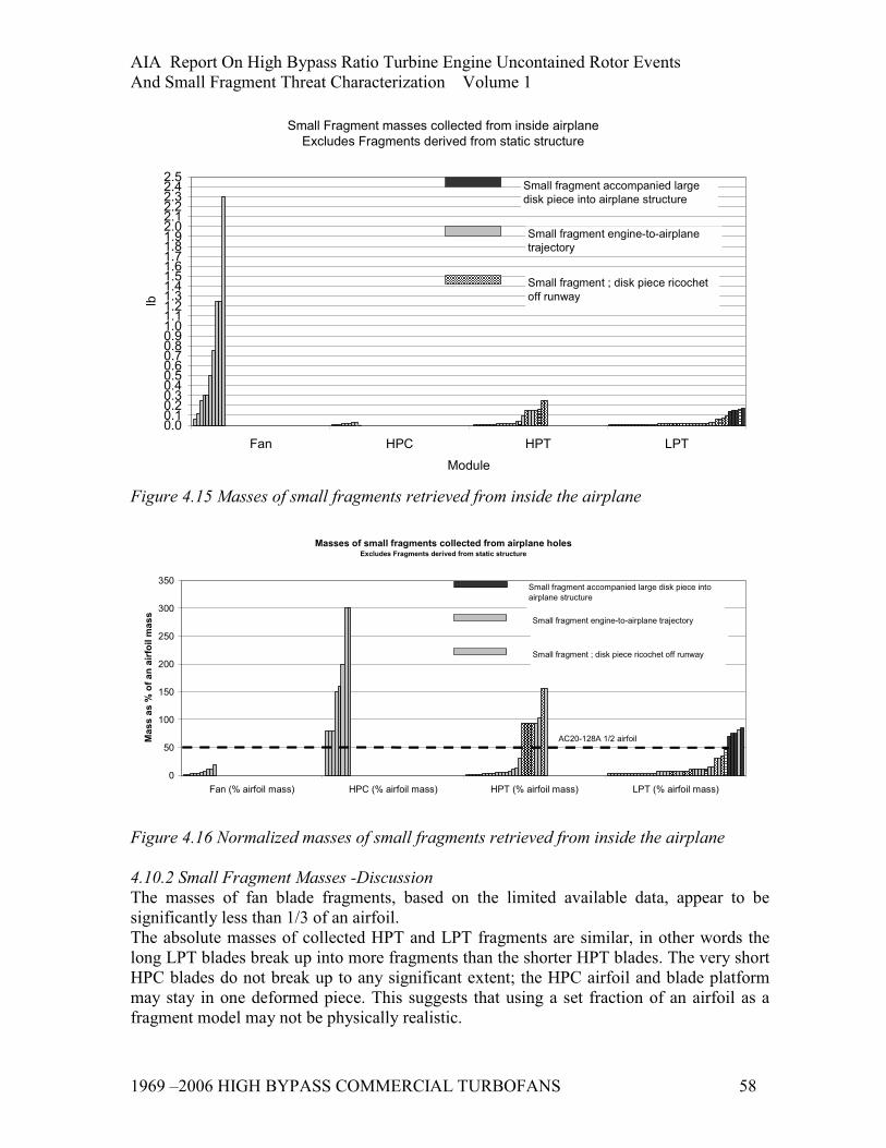
AIA Report On High Bypass Ratio Turbine Engine Uncontained Rotor Events And Small Fragment Threat Characterization Volume 1
1969 –2006 HIGH BYPASS COMMERCIAL TURBOFANS 58
Figure 4.15 Masses of small fragments retrieved from inside the airplane
Figure 4.16 Normalized masses of small fragments retrieved from inside the airplane
4.10.2 Small Fragment Masses -Discussion The masses of fan blade fragments, based on the limited available data, appear to be significantly less than 1/3 of an airfoil. The absolute masses of collected HPT and LPT fragments are similar, in other words the long LPT blades break up into more fragments than the shorter HPT blades. The very short HPC blades do not break up to any significant extent; the HPC airfoil and blade platform may stay in one deformed piece. This suggests that using a set fraction of an airfoil as a fragment model may not be physically realistic.
Small Fragment masses collected from inside airplaneExcludes Fragments derived from static structure
0.00.10.20.30.40.50.60.70.80.91.01.11.21.31.41.51.61.71.81.92.02.12.22.32.42.5
Fan HPC HPT LPT
Module
lb
Small fragment accompanied large disk piece into airplane structure
Small fragment ; disk piece ricochet off runway
Small fragment engine-to-airplane trajectory
Masses of small fragments collected from airplane holesExcludes Fragments derived from static structure
0
50
100
150
200
250
300
350
Fan (% airfoil mass) HPC (% airfoil mass) HPT (% airfoil mass) LPT (% airfoil mass)
Mas
s as
% o
f an
airf
oil m
ass
Small fragment accompanied large disk piece into airplane structure
Small fragment ; disk piece ricochet off runway
Small fragment engine-to-airplane trajectory
AC20-128A 1/2 airfoil

AIA Report On High Bypass Ratio Turbine Engine Uncontained Rotor Events And Small Fragment Threat Characterization Volume 1
1969 –2006 HIGH BYPASS COMMERCIAL TURBOFANS 59
It is clear that HPT ground events with ricochets generate more fragments with higher masses than events without ricochet . These high–mass fragments were the fir trees of HPT blades, rather than pieces of HPT airfoil. HPT fir trees have only been collected from holes in the airplane after disk-ricochet events. It also appears that LPT fragments generated in ricochet events may have higher masses than non-ricochet events.
4.11 Fragment release speeds 4.11.1 Small Fragment Speeds - Previous work Understanding of fragment speeds and energies has been evolving over time. Early observations were based upon a limited number of events; as additional data has become available, it has provided new perspectives and alternative interpretations of the evidence.
4.11.2 Large Disk Fragment speed -results As noted above, technical opinions have varied regarding the speed with which fragments leave the engine. In an effort to understand the release speeds of small fragments, the release speeds of large disk fragments were assessed. The disk uncontained events were reviewed to establish whether the speeds of the large disk fragments could be deduced from the evidence collected. In many cases, there was not enough evidence to establish the track of the disk fragment with regard to the airplane. However, 17 events had enough evidence to allow an estimate of the speed at which one or more of the large disk pieces departed the engine. This includes the 12 nacelle-contained or partially nacelle-contained events for which details were available. The details of this analysis are documented in Appendix 7. The results are summarized in Figure 4.17 (patterned bars). Figure 4.17 also shows, for comparison, the tangential speeds of those fragments just before the burst event, based on measured engine parameters (rotor rpm) and on the radius from engine centerline of each fragment centroid.
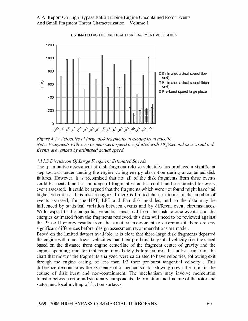
AIA Report On High Bypass Ratio Turbine Engine Uncontained Rotor Events And Small Fragment Threat Characterization Volume 1
1969 –2006 HIGH BYPASS COMMERCIAL TURBOFANS 60
Figure 4.17 Velocities of large disk fragments at escape from nacelle Note: Fragments with zero or near-zero speed are plotted with 10 ft/second as a visual aid. Events are ranked by estimated actual speed.
4.11.3 Discussion Of Large Fragment Estimated Speeds The quantitative assessment of disk fragment release velocities has produced a significant step towards understanding the engine casing energy absorption during uncontained disk failures. However, it is recognized that not all of the disk fragments from these events could be located, and so the range of fragment velocities could not be estimated for every event assessed. It could be argued that the fragments which were not found might have had higher velocities. It is also recognized there is limited data, in terms of the number of events assessed, for the HPT, LPT and Fan disk modules, and so the data may be influenced by statistical variation between events and by different event circumstances. With respect to the tangential velocities measured from the disk release events, and the energies estimated from the fragments retrieved, this data will need to be reviewed against the Phase II energy results from the structural assessment to determine if there are any significant differences before design assessment recommendations are made . Based on the limited dataset available, it is clear that these large disk fragments departed the engine with much lower velocities than their pre-burst tangential velocity (i.e. the speed based on the distance from engine centerline of the fragment center of gravity and the engine operating rpm for that rotor immediately before failure). It can be seen from the chart that most of the fragments analyzed were calculated to have velocities, following exit through the engine casing, of less than 1/3 their pre-burst tangential velocity . This difference demonstrates the existence of a mechanism for slowing down the rotor in the course of disk burst and non-containment. The mechanism may involve momentum transfer between rotor and stationary components, deformation and fracture of the rotor and stator, and local melting of friction surfaces.
ESTIMATED VS THEORETICAL DISK FRAGMENT VELOCITIES
0
200
400
600
800
1000
1200
HPCHPC
HPCHPC
LPT
HPCHPC
HPTHPC
HPCHPC
HPCHPC
FANHPT
HPTLP
T
FT/S
Estimated actual speed (lowend)Estimated actual speed (highend)Pre-burst speed large piece
AIA Report On High Bypass Ratio Turbine Engine Uncontained Rotor Events And Small Fragment Threat Characterization Volume 1
1969 –2006 HIGH BYPASS COMMERCIAL TURBOFANS 61
These results are likely to be relevant to determining values for small fragment speeds. Small fragments become detached from the disk during the burst process. They would likely have rotational speeds (rpm) similar to large or intermediate fragments; their tangential speed may be somewhat higher than that of large disk pieces, because they are further from the engine centerline prior to the failure event. (This might be offset by the blades being the first elements to encounter and rub against the casings, so that detached fragments had proportionally more energy absorption occur.) Table 4.10 estimates small fragment velocities based on the large fragment velocities, ratioed for the increased distance from engine centerline. Given that the fragment energy is proportional to the square of the speed, it can be seen that a fragment released with 1/3 the pre-burst tangential velocity would have 1/9 of the pre-burst energy. The implications for expected small fragment kinetic energy is very significant
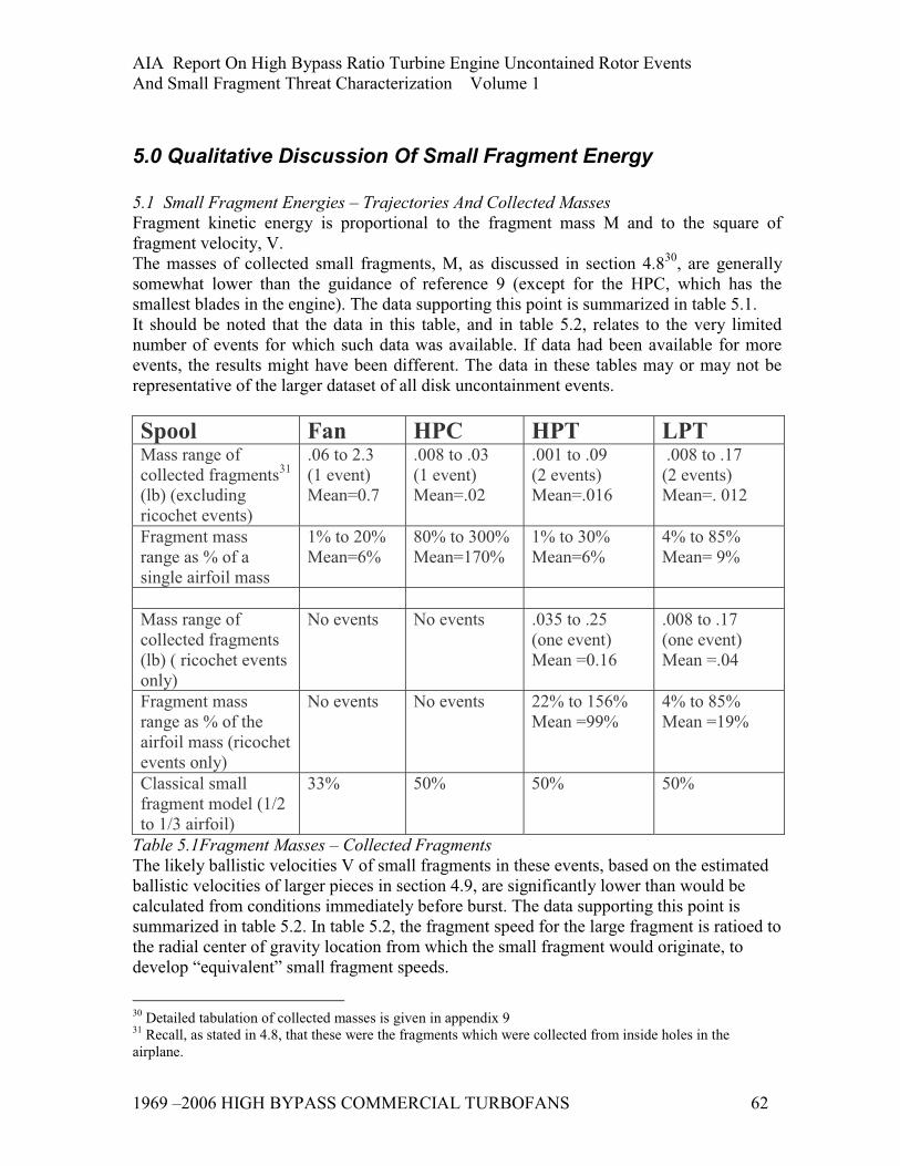
AIA Report On High Bypass Ratio Turbine Engine Uncontained Rotor Events And Small Fragment Threat Characterization Volume 1
1969 –2006 HIGH BYPASS COMMERCIAL TURBOFANS 62
5.0 Qualitative Discussion Of Small Fragment Energy
5.1 Small Fragment Energies – Trajectories And Collected Masses Fragment kinetic energy is proportional to the fragment mass M and to the square of fragment velocity, V. The masses of collected small fragments, M, as discussed in section 4.830, are generally somewhat lower than the guidance of reference 9 (except for the HPC, which has the smallest blades in the engine). The data supporting this point is summarized in table 5.1. It should be noted that the data in this table, and in table 5.2, relates to the very limited number of events for which such data was available. If data had been available for more events, the results might have been different. The data in these tables may or may not be representative of the larger dataset of all disk uncontainment events.
Spool Fan HPC HPT LPT Mass range of collected fragments31
(lb) (excluding ricochet events)
.06 to 2.3 (1 event) Mean=0.7
.008 to .03 (1 event) Mean=.02
.001 to .09 (2 events) Mean=.016
.008 to .17 (2 events) Mean=. 012
Fragment mass range as % of a single airfoil mass
1% to 20% Mean=6%
80% to 300% Mean=170%
1% to 30% Mean=6%
4% to 85% Mean= 9%
Mass range of collected fragments (lb) ( ricochet events only)
No events No events .035 to .25 (one event) Mean =0.16
.008 to .17 (one event) Mean =.04
Fragment mass range as % of the airfoil mass (ricochet events only)
No events No events 22% to 156% Mean =99%
4% to 85% Mean =19%
Classical small fragment model (1/2 to 1/3 airfoil)
33% 50% 50% 50%
Table 5.1Fragment Masses – Collected Fragments The likely ballistic velocities V of small fragments in these events, based on the estimated ballistic velocities of larger pieces in section 4.9, are significantly lower than would be calculated from conditions immediately before burst. The data supporting this point is summarized in table 5.2. In table 5.2, the fragment speed for the large fragment is ratioed to the radial center of gravity location from which the small fragment would originate, to develop “equivalent” small fragment speeds.
30 Detailed tabulation of collected masses is given in appendix 9 31 Recall, as stated in 4.8, that these were the fragments which were collected from inside holes in the airplane.
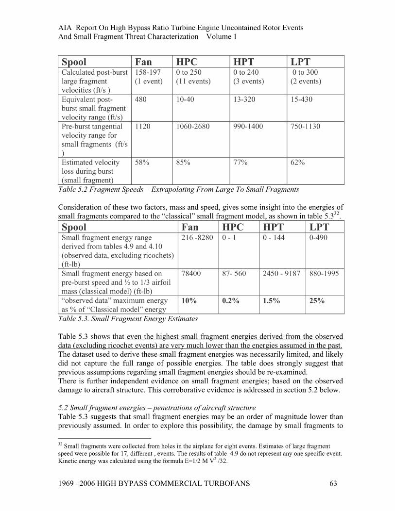
AIA Report On High Bypass Ratio Turbine Engine Uncontained Rotor Events And Small Fragment Threat Characterization Volume 1
1969 –2006 HIGH BYPASS COMMERCIAL TURBOFANS 63
Spool Fan HPC HPT LPT Calculated post-burst large fragment velocities (ft/s )
158-197 (1 event)
0 to 250 (11 events)
0 to 240 (3 events)
0 to 300 (2 events)
Equivalent post-burst small fragment velocity range (ft/s)
480 10-40 13-320 15-430
Pre-burst tangential velocity range for small fragments (ft/s )
1120 1060-2680 990-1400 750-1130
Estimated velocity loss during burst (small fragment)
58% 85% 77% 62%
Table 5.2 Fragment Speeds – Extrapolating From Large To Small Fragments
Consideration of these two factors, mass and speed, gives some insight into the energies of small fragments compared to the “classical” small fragment model, as shown in table 5.332. Spool Fan HPC HPT LPT Small fragment energy range derived from tables 4.9 and 4.10 (observed data, excluding ricochets) (ft-lb)
216 -8280 0 - 1 0 - 144 0-490
Small fragment energy based on pre-burst speed and ½ to 1/3 airfoil mass (classical model) (ft-lb)
78400 87- 560 2450 - 9187 880-1995
“observed data” maximum energy as % of “Classical model” energy
10% 0.2% 1.5% 25%
Table 5.3. Small Fragment Energy Estimates
Table 5.3 shows that even the highest small fragment energies derived from the observed data (excluding ricochet events) are very much lower than the energies assumed in the past. The dataset used to derive these small fragment energies was necessarily limited, and likely did not capture the full range of possible energies. The table does strongly suggest that previous assumptions regarding small fragment energies should be re-examined. There is further independent evidence on small fragment energies; based on the observed damage to aircraft structure. This corroborative evidence is addressed in section 5.2 below.
5.2 Small fragment energies – penetrations of aircraft structure Table 5.3 suggests that small fragment energies may be an order of magnitude lower than previously assumed. In order to explore this possibility, the damage by small fragments to 32 Small fragments were collected from holes in the airplane for eight events. Estimates of large fragment speed were possible for 17, different , events. The results of table 4.9 do not represent any one specific event. Kinetic energy was calculated using the formula E=1/2 M V2 /32.
AIA Report On High Bypass Ratio Turbine Engine Uncontained Rotor Events And Small Fragment Threat Characterization Volume 1
1969 –2006 HIGH BYPASS COMMERCIAL TURBOFANS 64
known airplane structure was analyzed. The concept was to back-calculate fragment energy based on the observed damage (e.g. a hole through a given skin thickness) . A review of the literature showed that the experimental data relating ballistic energy to skin thickness had considerable disagreement between results, to the point that it could not be used for this purpose. The experimental results are believed to be very sensitive to the test set-up and to the projectile shape. It was therefore decided to derive the fragment energy to damage a given skin thickness by DYNA modeling. Initial DYNA runs showed that the outcome was very sensitive to the presentation of the fragment at the instant of impact. A corner-on impact would allow penetration by a much lower energy fragment than a face-on impact. For example, initial modeling showed that the fragment orientation at the moment of impact could change the energy required to just make a hole from 8.5 ft-lb (corner impact) to 174 ft-lb (face impact)33. Since the presentation of a fragment which made a given hole in the airplane was not generally known, this observed sensitivity ruled out a deterministic matching of each structural hole to a known energy required to make that hole. Preliminary results of the modeling indicate that the energy required to just hole a .04 sheet of 2024 Al is between a few tens and a few hundred ft-lb, depending on trajectory and orientation. Referring back to Figure 4.10 and 4.11, it has been shown that for all disk uncontainments aggregated, approximately 10% of the small fragments impacting .04” thick aluminum airplane skin have sufficient energy to make a hole. This would imply that 90% of small fragments have energies less than the “few tens to few hundreds of ft-lbs” range. This result is very consistent with the “observed data” fragment energy ranges presented in table 4.11, and corroborates that small fragment energies may have been overestimated in the past.
5.3 Phase II The work presented above provides insight into the likely energies of small fragments. It does not address the highest energy small fragments – those which made holes in structure, passed through the holes and still had residual kinetic energy. Further analysis is planned in phase II of this project, which will address this issue. The approach is to develop a probabilistic model as follows: As noted above, the orientation of the fragment at impact is unknown for the majority of holes and dents. A wide range of fragment energies could have resulted in each individual hole or impact mark. However, the holes and impact marks in airplane structure often appear in groups rather than as single impacts. There are typically enough impact marks to safely assume there was a random fragment orientation34at the time of impact. The energy distribution of the group of fragments will combine with that random fragment orientation to result in the observed group of holes and dents.
33 Preliminary modeling by a manufacturer, approximating an HPT blade airfoil. 0.04 Aluminum target, model fragment approximated an HPT airfoil section, being a rectangular prism weighing 0.1 lb and with dimensions 1.7” x 0.17” x 1.2”. 34 The fragments released during a disk burst are known to be tumbling. The fragment element closest to engine centerline had a different tangential velocity than the fragment element furthest from engine centerline – so the fragment has some angular momentum when it separates from the rotor assembly.
AIA Report On High Bypass Ratio Turbine Engine Uncontained Rotor Events And Small Fragment Threat Characterization Volume 1
1969 –2006 HIGH BYPASS COMMERCIAL TURBOFANS 65
This allows the use of a statistical approach in deriving fragment energies, addressing a population of fragments rather than a single fragment.
Computer modeling, such as LS-DYNA can be used to model impact dynamics. Appropriate, realistic material failure modes can be selected for the modeling process based on photographic evidence of the holes after a disk burst event (provided in appendix 9). The computer modeling can be used to derive the probability of penetration by a given fragment and with a given target structure, as a function of fragment energy. The result is a probability of penetration, rather than a deterministic “does/does not penetrate” because of the random fragment orientation at impact. Once fragment penetration probability is known as a function of fragment energy (referred to as the orientation function from here on), the fragment energy distribution for a given event can be approximated using an iterative, numerical approach. A trial energy distribution can be hypothesized, the orientation function can be applied to it, and the ratio of holes: total impacts for that energy distribution can be calculated. This may be compared to the actual observed ratio of holes: impacts for the event, and the assumed energy distribution fine-tuned until the calculated and observed ratios match. Phase II of this work may also investigate the effect of fragment trajectory incidence upon penetration of a skin.

AIA Report On High Bypass Ratio Turbine Engine Uncontained Rotor Events And Small Fragment Threat Characterization Volume 1
1969 –2006 HIGH BYPASS COMMERCIAL TURBOFANS 66
6.0 Discussion 6.1 Previous studies
6.1.1 Engine –level reports In 1974, the NTSB published NTSB-AAS-74-4, “Special Study – Turbine Engine Rotor Disk failures”. This was primarily focused on low bypass engines, but did include six (first generation) high bypass engine events. The NTSB safety recommendations focused on a goal of disk containment.
In 1977, a seminar was hosted by MIT to address technical consideration for turbojet engine rotor failures (Reference 3). It included an important paper by D McCarthy of Rolls-Royce presenting event rates, observed disk fragmentation patterns, fragment sizes, weights, energy, and debris spread angles for the RR fleet (1950 – 1976). The data in this paper was critical to the early development of debris models. G Gunstone of the CAA also presented a paper showing overall and disk-burst non-containment rates (1966-1975, worldwide data) and giving some indication of flight phases. This paper provided the original thought process for the “1 in 20” certification requirement for airplane design against disk burst. It clearly states that the intent was to limit the chance of a catastrophe occurring to an airplane as a result of being struck by a piece of disk to less than 1E-8/ airplane hour. The logic path was as follows: The incidence of uncontained events of all kinds was 1E-6/engine hour. Approximately 1 in 4 of these caused airplane damage outside the nacelle; the “significant” uncontainment rate was therefore established as 1E-6/ airplane hour. In the interest of practicability and to avoid undue conservatism in the analysis, a goal of 1 in 20 for a Catastrophic outcome was set for the large disk piece. This goal was published in advisory material by the regulatory authorities, together with suggested design measures to mitigate against the systems effects of disk burst, in 1981 (Europe) and 1997 (US).
The SAE published reports on aircraft engine containment; AIR 1537 (1962 through 1975) and AIR 4003 (1976 through 1983). A third report, AIR 4770 (1984 – 1989) was prepared but never published. Each of these (references 4 through 6) provided a detailed analysis of disk, spacer and blade non-containment events, rates, and causal factors, for the commercial transport fleet. Data on airplane effects was very limited.
Delucia, Salvino, Fenton et al produced a series of statistical reports on “Aircraft Gas Turbine Engine Rotor Failures” covering US commercial aviation in the late 1980s. The reports’ definition of “rotor failure” encompassed many kinds of turbomachinery failures, and the reports are therefore less specific to uncontained events than the SAE reports.
6.1.2 Airplane-level consequence studies The AIA CAAM committee (Continued Airworthiness Assessment Methodology) developed two technical reports at the request of the FAA, compiling data on a variety of engine failure modes and associated conditional probabilities (hazard ratios) of airplane damage, including disk and blade uncontainment. These two reports covered the time

AIA Report On High Bypass Ratio Turbine Engine Uncontained Rotor Events And Small Fragment Threat Characterization Volume 1
1969 –2006 HIGH BYPASS COMMERCIAL TURBOFANS 67
periods 1982 – 1991 and 1992 – 2000, and addressed the western-built commercial transport fleet (fixed wing). Event rates were calculated as a function of airplane departures. These reports are published by the FAA.
The FAA Hughes Technical Center sponsored and coordinated collection of industry data on engine uncontained debris and the airplane damage effects, (conducted by the Naval Air Warfare Center; Weapons Division – C Frankenberger, Reference 2) to support updating Advisory Circular AC 20-128A. This is an important and relatively recent study, and merits discussion in some detail. Reference 2 presented data for more than 60 commercial transport turbofan uncontained disk and blade failures, 1961 – 1998, with approximately equal numbers of low and high bypass ratio engine events. The analysis focused on debris characterization, trajectory angles and derivation of energy levels and barrier thicknesses/materials to protect against debris. Reference 2 recommended further data collection to validate the assumptions and analysis used to derive fragment energies and other parameters. This AIA study implements this recommendation, and augments/ updates the uncontained rotor events on high bypass ratio engines, providing a broader perspective on the range of events. Specific examples of issues in reference 2 which have prompted further study and fresh insight, in this AIA report, include: �� Reference 2 used both low bypass and high bypass data. There is some question over the applicability of low bypass data to high bypass engines; this AIA study uses high bypass data only. �� The data used for reference 2 was normalized before publication in reference 2 and the original database is not available; visibility of the original data has been lost. This AIA report affords greater transparency so that additional analysis can be performed by interested parties. �� Reference 2 did not use data from the less damaging events and impacts, although it intended the data to be “representative”; the analysis therefore reflected only the more severe impact damage and the more severe events. The limited information available to the authors led to conclusions which appeared very different from the experience of accident investigators, and this prevented the ARAC group from reaching consensus in their work on AC 20-128B. For example, Reference 2 concluded, based on ten instances of fan blade non-containment, that there was an average of 8 airplane damages per event and that 10% of the fragments would cause system damage beyond the affected propulsion system. This report documents close to 150 forward-arc fan blade uncontainments, only 30 of which resulted in any airplane damage beyond the affected nacelle, and only one fragment damaging a system beyond the physical envelope of the affected propulsion system. It also documents 15 fan blade casing-uncontainments, 9 of which resulted in damage beyond the affected nacelle, and with three fragments35 causing system damage beyond the affected propulsion system. The larger dataset clearly leads to very different conclusions about the likely result of a fan blade uncontainment. �� Reference 2 did not differentiate between holes made in light aerodynamic fairings and structures such as wing skin or pressurized fuselage skin, nor did it publish data of the construction of the airplane structure which was holed. Negative data- such as impacts
35 Including, for this purpose, damage to windows causing cabin decompression
AIA Report On High Bypass Ratio Turbine Engine Uncontained Rotor Events And Small Fragment Threat Characterization Volume 1
1969 –2006 HIGH BYPASS COMMERCIAL TURBOFANS 68
which did not hole the airplane – were not recorded. Assumptions were made regarding typical structural thicknesses, which may not have applied to the specific event. This report documents actual construction and skin thicknesses which were holed or dented. �� Reference 2 used the hole size to estimate the fragment size (damage ratio), leading to some very large estimated fragment sizes. The role of glancing impacts and fragment tumbling in creating long tears in airplane skin, much larger than the fragment, was mentioned, as was the difference between estimated sizes based on holes and measurement of collected fragments. This difference was noted but not resolved in reference 2; the AIA report provides additional data on collected fragment masses. �� Assumptions were made in reference 2 regarding the energy absorption of fragments in the uncontainment process; and further work to validate these assumptions was recommended. For instance, it was assumed that the small debris exited through an ”existing hole in the engine case caused by a disk segment”: and then lost 25% of its velocity in holing the engine cowling. This AIA study explores the fragment energies after uncontainment of a disk; initial data suggests that the small fragments lose considerable velocity and energy during the uncontainment process and that velocity loss may be in the range of 60% to 90%; further work is planned to verify this. �� Reference 2 did not have sufficient data available on high bypass ratio HP compressor events to draw conclusions regarding the role of the thrust reverser in capturing uncontained fragments, and recommended further research on this issue. This report provides that data . This AIA study implements the recommendation of validating assumptions, and augments/ updates the uncontained rotor events on high bypass ratio engines, providing a broader perspective on the range of events. This AIA study also provides a historical perspective on the state of the art with regard to rotor burst issues.
AIA Report On High Bypass Ratio Turbine Engine Uncontained Rotor Events And Small Fragment Threat Characterization Volume 1
1969 –2006 HIGH BYPASS COMMERCIAL TURBOFANS 69
6.2 Probabilistic design goals
The 1 in 20 criterion, also recognized as a conditional probability, for catastrophic loss of the airplane following release of 1/3 disk (Reference 9) was developed to assess whether the airplane systems and structural design are sufficiently robust when analyzed for an idealized 1/3 disk fragment. The analysis is based on conservative assumptions, and serves as a yard stick against which the airplane design can be measured as a standardized case to demonstrate acceptable capability or assess incremental change effects. It is not an analysis to forecast the airplane’s behavior for the vast range of conceivable disk failure scenarios. However, there is a demonstrated relationship between the conditional probability calculated for certification, and the historically observed behavior of the airplane given disk failure events. Even though the calculated numbers are not necessarily identical which may include differing risk rates among contributing factors, the first order correlation between design predictions and service experience has been borne out over time – i.e. a very high design related conditional probability of loss of the airplane suggests there would be a high risk in reality.
Of the 58 nacelle-uncontained disk bursts in the high bypass ratio fleet, three resulted in a level 4 (2) or level 5 (1) events. When combining the level 4 and 5 events which corresponds to the range of Severe Hazardous to Catastrophic, this represents an observed hazard ratio of .052, near 1 in 20. It is recognized that lumping level 4 events with level 5 provide a conservative data set as the basis. In addition, as mentioned in section 3.3, there here have been 2 additional disk failure events that occurred post 2006 which have not been included in above calculations which would yield 3 in 60. The 3 severity classifications were due to: �� Multiple system damage by small and intermediate fragments �� Ricocheting small fragments holing a fuel tank. �� Ricochet impacts by large and small pieces holing fuel tanks. This observed hazard ratio includes all the variability and physical complexity of the real world, such as ricochet effects, multiple fragments, irregular fragment shapes, conditional probability of leaked fuel specific to the ambient conditions and ignitions sources, etc. Although some of these aspects of disk burst scenarios and/or conditions are omitted from the simplified assumptions of the design calculation, the 1 in 20 objective has been achieved to date; despite the fact that the historical fleet includes a large percentage fleet of airplanes designed before the 1 in 20 criterion, and the associated mitigating design measures36, were devised. It is recognized that good design practices that minimize the risk of catastrophic effects like systems architecture, separation, routing, redundancy, isolation, and shielding have played a role in the observed 1 in 20 results and it is recognized these design precaution philosophies should continue with future designs as well as the current 1 in 20 assessment. Had the 1 in 20 criterion, and the associated mitigating design measures, been applied to the whole high bypass fleet, the observed hazard ratio would likely have been less than 3 in 58.
36 System redundancy, isolation, separation, routing outside the debris zone and /or shielding
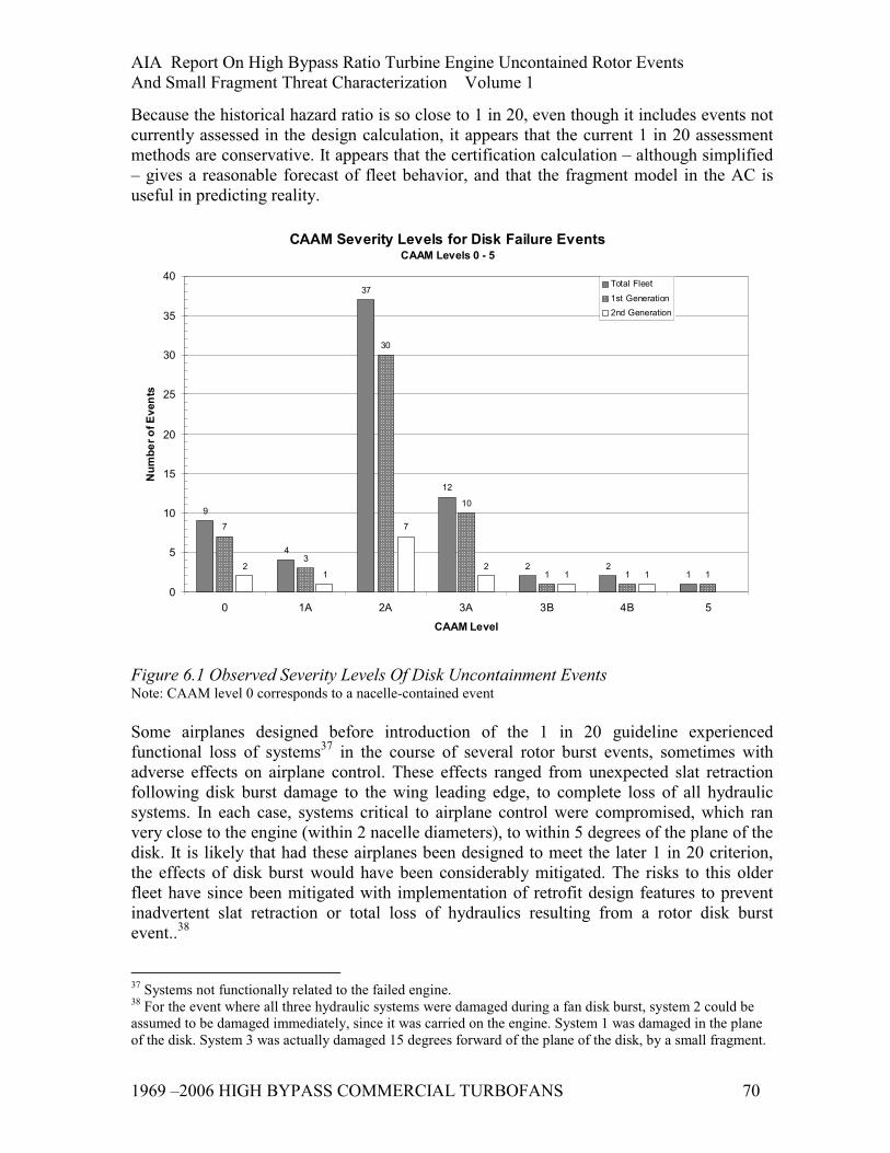
AIA Report On High Bypass Ratio Turbine Engine Uncontained Rotor Events And Small Fragment Threat Characterization Volume 1
1969 –2006 HIGH BYPASS COMMERCIAL TURBOFANS 70
Because the historical hazard ratio is so close to 1 in 20, even though it includes events not currently assessed in the design calculation, it appears that the current 1 in 20 assessment methods are conservative. It appears that the certification calculation – although simplified – gives a reasonable forecast of fleet behavior, and that the fragment model in the AC is useful in predicting reality.
Figure 6.1 Observed Severity Levels Of Disk Uncontainment Events Note: CAAM level 0 corresponds to a nacelle-contained event
Some airplanes designed before introduction of the 1 in 20 guideline experienced functional loss of systems37 in the course of several rotor burst events, sometimes with adverse effects on airplane control. These effects ranged from unexpected slat retraction following disk burst damage to the wing leading edge, to complete loss of all hydraulic systems. In each case, systems critical to airplane control were compromised, which ran very close to the engine (within 2 nacelle diameters), to within 5 degrees of the plane of the disk. It is likely that had these airplanes been designed to meet the later 1 in 20 criterion, the effects of disk burst would have been considerably mitigated. The risks to this older fleet have since been mitigated with implementation of retrofit design features to prevent inadvertent slat retraction or total loss of hydraulics resulting from a rotor disk burst event..38
37 Systems not functionally related to the failed engine. 38 For the event where all three hydraulic systems were damaged during a fan disk burst, system 2 could be assumed to be damaged immediately, since it was carried on the engine. System 1 was damaged in the plane of the disk. System 3 was actually damaged 15 degrees forward of the plane of the disk, by a small fragment.
CAAM Severity Levels for Disk Failure EventsCAAM Levels 0 - 5
9
4
37
12
2 21
7
3
30
10
1 1 12
1
7
21 1
0
5
10
15
20
25
30
35
40
0 1A 2A 3A 3B 4B 5
CAAM Level
Num
ber o
f Eve
nts
Total Fleet
1st Generation2nd Generation
AIA Report On High Bypass Ratio Turbine Engine Uncontained Rotor Events And Small Fragment Threat Characterization Volume 1
1969 –2006 HIGH BYPASS COMMERCIAL TURBOFANS 71
In contrast, those airplanes designed after the introduction of the 1 in 20 guideline have not experienced systems damage leading to a level 3, 4 or 5 event. It is recognized that they have experienced fewer disk burst events than the earlier designs, and there is not yet enough experience to prove that their systems design is more robust. However, the evidence of the combined first and second generation fleets is consistent with a 1 in 20 criterion being an effective means of controlling risk to airplane systems. It is notable that a significant part of the 1 in 20 risk calculated during certification assessment, for wing mounted engines, is for disk pieces travelling up through the wing to hit the fuselage and the systems therein. There is only one instance in high-bypass turbofan service experience where a large disk piece has hit the fuselage; this was a direct strike and did not hit the wing first. Large disk pieces with trajectories which would, geometrically, go through the wing and hit the fuselage, have been deflected by the wing and have not hit the fuselage, historically. There is a significant body of evidence that large or intermediate disk pieces travelling in the direction of the fuselage are often deflected or stopped when they strike the wing. The certification assessment appears conservative in this respect. It is also noted that in-service disk release during ground operations has led to large disk pieces hitting the ground and small fragments ricocheting up to hit the wing with significant energy, sufficient to penetrate wing skin and result in fuel leakage and a pool fire. This scenario is not addressed in the certification assessment; there are significant technical difficulties in doing so (see 6.3). It is not clear how to mitigate this concern at the airplane level without introducing other risks.
However, the overall risk of such an event is being mitigated at the engine level for new designs, by the systematic, sustained reduction in the rate of disk uncontained events and corrective actions for new events or significant discoveries found during the critical rotating parts inspection processes.
Finally, it is noted that the current rate of disk uncontainment for 3rd generation engines (2.5E-839/ engine cycle), combined with an observed 1 in 20 ( 3 in 58) hazard ratio of a Catastrophic consequence of disk uncontainment, would give an airplane level probability of 2.5E-9/flight of catastrophic disk uncontainment on a twin-engined airplane. This is on the order of, the 1E-9 level traditionally interpreted as being Extremely Improbable.
6.3 Ricochets It has been observed that fragments which strike the ground may ricochet in unpredictable directions. This limits the applicability of ground event trajectories to in-air events. In particular, events where a disk strikes the ground and generates further fragments have produced fragments very different from those produced during a normal disk burst.
However, there was at least one disk fragment trajectory within 5 degrees of the plane of the disk which could have damaged both systems 1 and 3 together. 39 There have been no 3rd generation events. If one is assumed to be imminent, then the rate is 2.5E-8/engine cycle, as discussed in section 2)
AIA Report On High Bypass Ratio Turbine Engine Uncontained Rotor Events And Small Fragment Threat Characterization Volume 1
1969 –2006 HIGH BYPASS COMMERCIAL TURBOFANS 72
The fragments generated during a ricochet appear different from fragments in other events; they are heavier (see table 4.9, figures 4.15 and 4.16). Events involving ricochets have made very many more holes in airplane structure than events where a ricochet was not involved (Figure 4.5), and they have holed structure which is never holed by small fragments in other events. It is concluded that the energies of small fragments in ricochet events may be significantly higher than in non-ricochet events. This is believed to be heavily influenced by an energetic fragment impacting with the runway surface. The ability to forecast the trajectories after a disk fragment breaks up on impact with a runway surface would require agreement on major assumptions used in a modeling approach. The conversion from rotational to translational energy during the ricochet process would also complicate the ability to accurately predict the trajectories. It is recommended that attempts to model ricochets be deferred until the technical community has reached consensus on the energies of the more frequently encountered “normal” small fragments. Modeling ricochet events is not considered to be within the state of the art analysis methods nor are there guidelines established to determine whether or not the ricochet condition is acceptable or not.
Consideration of ricochets has not formed part of rotor burst analysis in the past, since the trajectories of such fragments cannot be predicted. It should be noted that damage to airplane systems critical to airplane control has not happened in ricochet events; they do not appear to pose a greater threat of critical systems damage. Ricochet events do appear to involve a greater risk of wing skin penetration and fuel tank leaks. It is not clear that any means exists to mitigate this possibility, apart from reducing the likelihood of the initial disk burst. It is recommended that ricochets should not be separately addressed, since attempts to explicitly incorporate ricochets would greatly increase the difficulty of modeling, could not be validated, and would likely produce negligible design improvement. The airplane level effects from ricocheting small fragments are qualitatively no different from the effects that would be caused by a large disk fragment; fragment sizes, energies and time window of concern40 are significantly less than for the large disk fragment. Similarly, it is recommended that data from events involving ricochets be excluded from any fragment models.
40 Takeoff roll.
AIA Report On High Bypass Ratio Turbine Engine Uncontained Rotor Events And Small Fragment Threat Characterization Volume 1
1969 –2006 HIGH BYPASS COMMERCIAL TURBOFANS 73
6.4 Small Fragment Model
Both industry and regulators have spent considerable effort in considering the most appropriate way to account for small fragments when designing to mitigate the effects of rotor burst, and certifying the design. The current approach, as presented in reference 9, includes the following features: �� Design for a small fragment, but do not include it in probabilistic analysis (1 in 20) �� Small fragment is 1/3 fan airfoil or ½ other airfoil �� Fragment is travelling at red-line tangential speed�� Fragment stays within + 15 of plane of disk.
The data presented in this report suggests that the fragment size and disk speed cited above represent extreme conditions, the worst that had been seen or extrapolated by the ARAC group compiling the guidance. Combination of these parameters (fragment size, disk speed) produces a “design fragment” far outside experience. As illustrated in figure 2.4 and throughout this report, there is considerable variability in fragments and events, so that any model can be criticized as only representing a small subset of events. It is also noted in section 4 that most small fragments do not have enough energy to hole the airplane skin, and that few small fragments holing airplane skin damaged a system or second layer inside the hole. Where there were holes, very few small fragments were collected from inside (many did not pass through the holes into the airplane). It is further noted that there is only one instance of small fragments causing systems damage which would or could affect airplane controllability. The threat from small fragments to systems inside the airplane appears relatively low, and may not merit a combination of all worst-case assumptions. Airplane manufacturers have also observed that, where probabilistic risk assessments have been done, the incremental risk from a small fragment is extremely small compared to the risk from a large fragment. However, reference 9 also contains guidance that shielding by fuselage pressure skin or equivalent is considered effective protection against small fragments. Review of the airplanes in this study suggests a typical fuselage pressure skin construction of 0.05” to 0.08” thick aluminum alloy. This level of structural protection would provide system protection against 96% of small fragments (based on Figure 4.11 and figure 4.12). The historic disk uncontainment involving systems damage by small fragments and consequent loss of the airplane, involved systems protected by 0.02” thick aluminum skin. It is recommended that use of .05” to .08” aluminum skin or equivalent, similar to the recommendation in reference 9, be considered to protect systems against small fragments.
AIA Report On High Bypass Ratio Turbine Engine Uncontained Rotor Events And Small Fragment Threat Characterization Volume 1
1969 –2006 HIGH BYPASS COMMERCIAL TURBOFANS 74
7.0 Conclusions The main conclusions of this work are presented below:
7.1 Disk uncontainment 7.1.1 In the time period between 1969 and 2006, there have been a total of 58 nacelle uncontained disk events. 46 of these events were from 1st generation engines and 12 were from 2nd generation engines. There have been no events from 3rd generation engines.
The overall occurrence rate of disk burst (includes spacers) has fallen by over 2 orders of magnitude since high bypass ratio (HBPR) engines entered service (Figure 3.2).
�� This reduction results from a series of industry and regulatory initiatives, directed at controlling and progressively reducing or eliminating the root causes of disk burst (Appendix 2).
�� There were no third generation disk burst events in the study period, if there had been one, the third generation cumulative rate would be 2.5 E-8/cycle). The incidence of disk burst for future design high bypass turbofans will likely be at least as good as that of third generation engines (Figure 3.2).
�� The rate of disk burst for each design generation has progressively decreased. Using the 5 year rolling average rate, the first generation engine rate is 6.9E-8/engine cycle and the combined second and third generation engine rate is 2.1E-8 /engine cycle. (.The incidence of Low Pressure and Intermediate Pressure (LP/IP) disk uncontainment is lower than that of High Pressure (HP) disk uncontainment. In particular, 2nd generation engines have had no LP/IP disk uncontainments from EIS to the end of 2006. This corresponds to a maximum rate of 4E-9/engine cycle when assuming 1 event for a rate calculation. (Figure 4.3).
7.1.2 The high bypass turbofan fleet, as a whole, has experienced 58 disk uncontainment events over the time period considered, three of which resulted in loss of the airplane. The results are consistent with the 1 in 20 criterion used during certification analysis, even though many (75%) of the events occurred on airplanes designed and certified before introduction of this criterion.
�� A probabilistic criterion for minimizing the effects of disk burst was proposed in the mid-1970s (Reference 3). It required that, given a disk burst, there should be no more than a 1 in 20 chance of a Catastrophic outcome from impact by a 1/3 disk fragment. So far, airplanes designed using that criterion and the associated mitigating design features have shown sufficient system robustness for continued safe flight after disk burst. In contrast, first generation high-bypass turbofan airplanes, which were designed before the criterion was published, have experienced systems damage affecting controllability on multiple occasions.
�� The damage instances to systems which affected airplane controllability all took place very close to the affected engine; within one or two nacelle diameters. In each case, the systems damage was from large or intermediate size fragments, or was to systems shielded by very light skin (.02” aluminum). (Table 4.7)
AIA Report On High Bypass Ratio Turbine Engine Uncontained Rotor Events And Small Fragment Threat Characterization Volume 1
1969 –2006 HIGH BYPASS COMMERCIAL TURBOFANS 75
7.1.3 The estimated third generation disk uncontainment rates, in conjunction with the historical observed hazard ratio for Catastrophic damage from 1/3 disk, provides a level of risk which is approaching an extremely improbable condition, commensurate with other accepted airplane design risks (paragraph 6.2).
7.1.4 More than 90% of disk bursts occur at low altitude (well below the 25,000 ft cited in 14 CFR Part 25 Section 25.863). These events have occurred during takeoff or initial (low altitude) climb (Figures 4.1 and 4.2).
7.1.5 Fires resulting from disk burst inflight have been controlled with the use of fuel shutoff means with no hazardous outcomes. On the ground, uncontrolled fires have resulted when significant quantities of fuel pools on the ground as a result of tank rupture following ground ricochet. No fatal injuries have resulted from these events. (Table 4.2 ). 7.1.6 There is evidence that nacelle and airplane heavy structure provides some degree of shielding from large and intermediate fragments. �� In most cases where a large or intermediate fragment hit the wing, it did not pass
through the wing, indicating that the wing provides some significant degree of shielding against a realistic large fragment.
�� Nacelle structure provides some containment or shielding capability for large and intermediate fragments. (Table 4.8)
7.1.7 The evidence of engine test and service experience indicates that in the event of a disk burst or loss of an entire fan blade, the engine is likely to stall very rapidly, cease producing useful thrust, and spool down. Evidence of fan blade off tests and service experience with disk burst indicates that stall typically occurs in the first 100 milliseconds.(Paragraph 4.2 , Appendix 4). �� It is considered highly unlikely that a disk burst resulting in deployment of a reverser
would produce significant reverse thrust effects. �� It is considered very likely that an engine departing the airplane as a result of disk burst
would drop away without any significant thrust vector. This is in contrast to an undamaged engine which departs the airplane as a result of an initial mount failure, while producing thrust.
7.2 Small Fragments Resulting From Disk Uncontainment
7.2.1 The evidence reviewed so far indicates that small fragments may have much lower energies than previously assumed. �� Very few disk bursts occur with the spool running at or above red line; the range 90 to 95% of red line appears more typical. (Figure 4.4). �� Analysis of a limited set of large disk fragment trajectories indicates that they were released from the engine at considerably lower speed than their tangential speed immediately prior to burst. Speeds based on trajectories, for this limited set, were less than 30% of pre-burst speeds. (Figure 4.17). Consequently, small fragments may also have much lower speeds than their tangential speed prior to burst.
AIA Report On High Bypass Ratio Turbine Engine Uncontained Rotor Events And Small Fragment Threat Characterization Volume 1
1969 –2006 HIGH BYPASS COMMERCIAL TURBOFANS 76
�� The masses of small fragments, collected from holes in the airplane, indicate that the extent to which blades break up is influenced by their initial size and construction. A larger blade will break into more pieces than a small blade, in the course of a disk burst. (Figures 4.15 and 4.16). �� The observed masses of small fragments (a limited data set) suggest that small fragments may have lower energy than previously assumed. The masses of small fragments collected from holes in airplane structure are generally lower for fan and turbine disk events than the 1/3 airfoil or ½ airfoil cited in reference 9 (AC 20-128A). �� Preliminary analysis of structural damage also suggests that small fragments may have much lower energies than has previously been assumed. (Paragraph 5.2) �� Most small fragments do not have enough energy to make holes in airplane structure. Of 8700 small fragment impacts, 450 made holes in the airplane. (Figure 4.11) . �� Most small fragments which make holes in the airplane do not have enough residual energy to damage systems or additional structural layers inside the hole. Of 450 small fragment holes, 27 fragments went on to damage systems or structure inside the hole. (Figure 4.12) . �� Small fragments involved in disk ricochets from the ground have very different energy, size and trajectories from in-flight events; Phase II will address these further.
7.3 Blade uncontainment
7.3.1 The rate of forward arc fan blade fragment non-containment has been reduced by several orders of magnitude since the first high bypass turbofans entered service. Robust fan blade design (including wide chord geometry) and moving A-flange forward have contributed to this reduction. (Appendix 3, Figure A.3.2.2)
7.3.2 The airplane level consequences of fan blade fragment forward arc non-containment are usually limited to a small number of superficial nicks, dents and holes in aerodynamic surfaces. (Appendix 3, Figure A.3.2.7) A few events have resulted in one or two small holes in the pressure skin (of the order of two inches across). There has been one CAAM level 3 event due to forward-arc uncontainment; this involved damage to a hydraulic system in an adjacent engine strut/pylon. 7.3.3 Design improvements have reduced the rate of casing uncontainment by blades by a factor of 50 since the first high bypass fans entered service. (Appendix 3, Figure A.3.3.2)
7.3.4 The airplane level consequences of casing uncontainment by blades vary according to the specific failure mode involved. Most events result in a small number of superficial nicks, dents and holes in aerodynamic surfaces. The release of multiple whole fan blades, or LPT vane/ nozzle spinning has resulted in more extensive damage. (Appendix 3, Figure A.3.3.4) �� There have been no IP or HP compressor blade releases outside the nacelle. (Appendix 3, paragraph A3.3.3.) �� There have been 2 fatal injury events due to 2 separate multiple fan blade non-containment events which punctured the fuselage window. In each event, a passenger was
AIA Report On High Bypass Ratio Turbine Engine Uncontained Rotor Events And Small Fragment Threat Characterization Volume 1
1969 –2006 HIGH BYPASS COMMERCIAL TURBOFANS 77
fatally injured. One event was on an second generation aft mounted engine installation and the second was on a wing mounted installation with first generation engines involving flight crew error operating the engine outside its certified limits. (Appendix 3, paragraph A3.3.3.)
7.3.5 Debris exiting the tailpipe is unlikely to impact the airplane with enough energy to leave a witness mark. When it has done so, the damage has been limited to small holes and dents in non-pressurized aerodynamic surfaces or nicks and small dents in fuselage or wing structure not causing hazardous effects or potential thereof. (Appendix 3, Table A.3.7)
8.0 Recommendations 1. The data herein are recommended for use in interpretation of existing policy and
guidance. In particular, when addressing mitigation, the following points should be considered:
The low incidence of disk uncontainment demonstrated by the 2nd/3rd
generation fleet. The continued emphasis on rotor integrity by design, manufacturing, and maintenance which has resulted in a steady reduction of the historical disk burst rate, both for existing engine models and for new models developed using lessons learned . The demonstrated systems robustness of airplanes designed to comply with the 1 in 20 criterion of a catastrophic outcome resulting from damage by a 1/3 disk fragment.The very low probability of disk burst occurring above 25,000 ft, and low consequent probability of high-altitude depressurization from disk burst. The relative likelihood of disk burst from different spools The minimal airplane damage caused by blade forward arc uncontainment and by tailpipe debris. The role of rapid spooldown of engines in avoiding significant inflight thrust reversal as a result of disk burst. The role of rapid spooldown of engines in avoiding catastrophic airplane damage from engine separation after disk burst.
2. Recognizing today’s current disk burst rates, and recognizing the historical 3 in 58 observed probability of disk burst leading to a Catastrophic outcome (from any and all fragment sizes), it is recommended that airplane designs which meet the 1 in 20 probabilistic criterion for a Catastrophic outcome from disk burst (large disk fragment) be interpreted as having met the intent of minimizing the hazard from rotor burst.
3. Airplane pressure skins in the locations of debris damage are typically .05 to .08” Al 2024. The data indicates that .05” to .08” aluminum will protect against system damage by over 96% of small fragments. (Figure 4.11 and 4.12). This data supports the use of shielding equivalent to pressure cabin skins, as recommended in
AIA Report On High Bypass Ratio Turbine Engine Uncontained Rotor Events And Small Fragment Threat Characterization Volume 1
1969 –2006 HIGH BYPASS COMMERCIAL TURBOFANS 78
AC20-128A ; it is therefore recommended that aluminum skin in the range .05 to .08” be considered as adequate shielding for systems outside the near-field zone.41.
4. Further work is recommended in phase II, to quantify the energies of small fragments based on the observed damage to airplane structure. This will enable assessment of the degree of shielding provided by materials other than sheet aluminum.
5. It is recommended that redundant critical systems be located out of the near-field zone (2 nacelle diameters from engine centerline), as far as is practicable, since the density of the small fragment debris pattern is very much greater close to the engine (conclusion 7.1.2). It is also recommended that mitigation of the effects of disk burst focus on near-field systems routing and robustness.
6. Since the data shows that existing aircraft structure provides adequate protection against small fragments, away from the near-field zone (conclusion 7.1.2 and 7.2.1), it is recommended that the current requirements should not be expanded to require probabilistic assessment for small fragments .
7. The use of small fragment energy based on ½ or 1/3 airfoil at the tangential speed immediately prior to burst is not recommended, based on the data summarized in conclusion 7.2.1 . A recommendation for a representative small fragment energy will be made once Phase II has quantified the small fragment energy distribution more exactly.
8. It is recommended that debris from fan blade forward arc travel and tailpipe debris continue to be regarded as low energy and as not presenting a threat to passengers or airplane systems (Conclusion 7.3.1 and 7.3.2).
9. The interpretation and application of 14 CFR Part 25 Section 25.841 should be reviewed to consider taking into account the low rate of disk burst in recent designs and the distribution of disk burst by flight phase and altitude. It should also take into account the relative improbability of the LP spool encountering a disk burst on the second/third generation engines. Elements which should be considered are:
i. Disk burst rate of <2.5E-8/engine cycle ii. Proportions of disk bursts above 25,000 ft (bounded by 1 in 13 for
second/third generation fleet, assuming 1 event although none have occurred)
iii. Relative frequencies of disk burst by spool for second/third generation fleet
10. It is recommended that future data collection and analysis discriminate between events above and below 25,000 ft
41 “ For protection against engine small fragments, as defined in Paragraph 9, no quantitative validation as defined in Paragraph 10 is required if equivalency to the penetration resistant structures listed (e.g. pressure cabin skins, etc.) is shown.”.
AIA Report On High Bypass Ratio Turbine Engine Uncontained Rotor Events And Small Fragment Threat Characterization Volume 1
1969 –2006 HIGH BYPASS COMMERCIAL TURBOFANS 79
9.0 References 1 NTSB recommendation A-90-172 “establish a system to monitor the engine rotary parts failure history of turbine engines and to support a data base sufficient for design assessment, comparative safety analysis among manufacturers, and more importantly, to establish a verifiable background for the FAA to research during certification review.”
2 Naval Air Warfare Center; Weapons Division – C Frankenberger. “Large Engine Uncontained Debris Analysis” DOT/FAA/AR-99/11, May 1999, NTIS
3 An assessment of technology for turbojet engine rotor failures , N78-10068-10090 , MIT, August 1977, NTIS
4 AIR 1537 Report on airplane engine containment, SAE October 1977
5 AIR 4003 Report on airplane engine containment, SAE September 1987
6 AIR 4770 (Draft D7) Report on airplane engine containment, SAE (unpublished)
7 Technical Report On Propulsion System and Auxiliary Power Unit (APU) Related Airplane Safety Hazards, October 1999, AIA/FAA
8 Second Technical Report On Propulsion System and Auxiliary Power Unit (APU) Related Airplane Safety Hazards, January 2005, AIA/FAA
9 AC20-128A Design Considerations for Minimizing Hazards caused by Uncontained Turbine Engine and Auxiliary Power Unit Rotor Failure, March 1997, FAA
10 Memo M-2 6/21/93, “A brief guide to uncontained turbine engine rotor events” JT Moehring, presented by RS Crandall at September 1994 Workshop on Uncontained Engine Rotor Fragment Description, Seattle, WA
11 Twin-engine transports - A look at the future TAYLOR, RICHARD W., Boeing Commercial Airplanes, Seattle, WA AIAA-1990-3215 AHS, and ASEE, Aircraft Design, Systems and Operations Conference, Dayton, OH, Sept 17-19, 1990. 15 p.
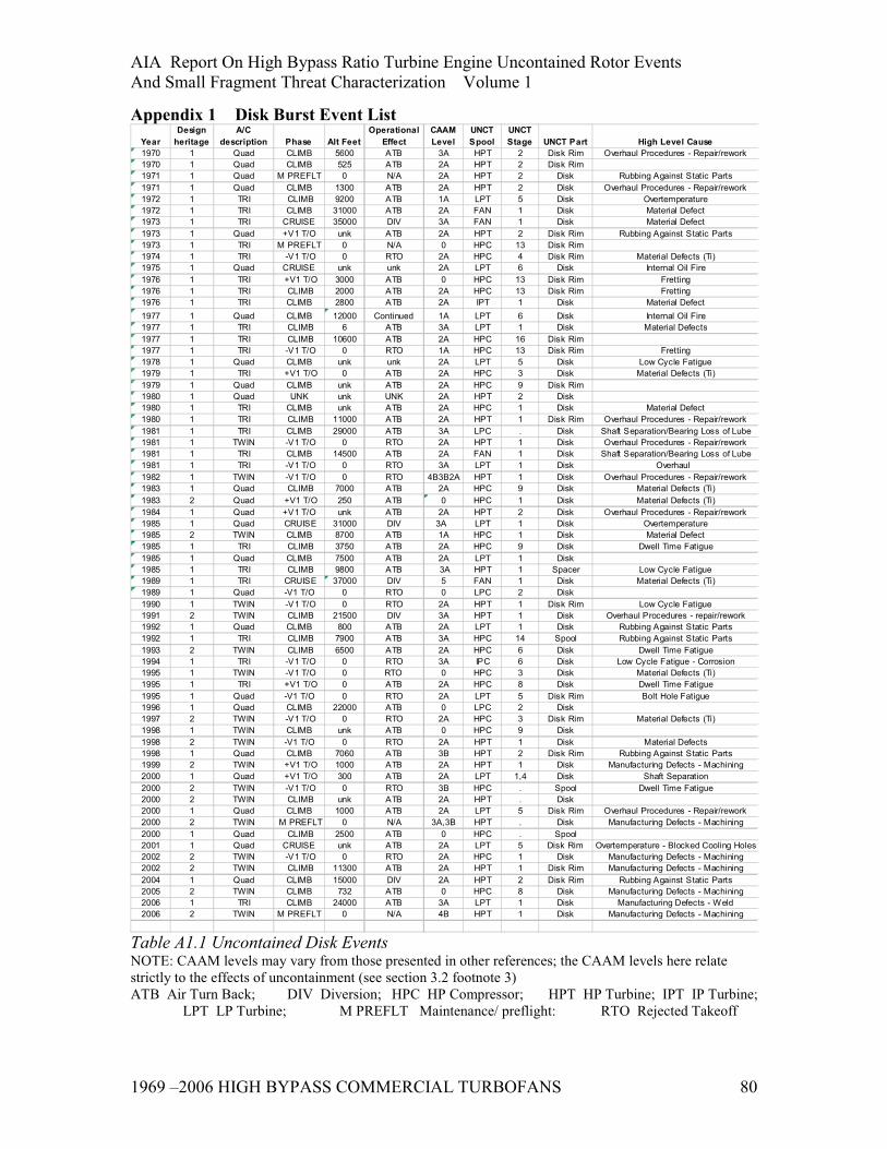
AIA Report On High Bypass Ratio Turbine Engine Uncontained Rotor Events And Small Fragment Threat Characterization Volume 1
1969 –2006 HIGH BYPASS COMMERCIAL TURBOFANS 80
Appendix 1 Disk Burst Event List
Table A1.1 Uncontained Disk Events NOTE: CAAM levels may vary from those presented in other references; the CAAM levels here relate strictly to the effects of uncontainment (see section 3.2 footnote 3) ATB Air Turn Back; DIV Diversion; HPC HP Compressor; HPT HP Turbine; IPT IP Turbine; LPT LP Turbine; M PREFLT Maintenance/ preflight: RTO Rejected Takeoff
YearDesign
heritageA/C
description Phase Alt FeetOperational
EffectCAAM Level
UNCT Spool
UNCT Stage UNCT Part High Level Cause
1970 1 Quad CLIMB 5600 ATB 3A HPT 2 Disk Rim Overhaul Procedures - Repair/rework1970 1 Quad CLIMB 525 ATB 2A HPT 2 Disk Rim1971 1 Quad M PREFLT 0 N/A 2A HPT 2 Disk Rubbing Against Static Parts1971 1 Quad CLIMB 1300 ATB 2A HPT 2 Disk Overhaul Procedures - Repair/rework1972 1 TRI CLIMB 9200 ATB 1A LPT 5 Disk Overtemperature1972 1 TRI CLIMB 31000 ATB 2A FAN 1 Disk Material Defect1973 1 TRI CRUISE 35000 DIV 3A FAN 1 Disk Material Defect1973 1 Quad +V1 T/O unk ATB 2A HPT 2 Disk Rim Rubbing Against Static Parts1973 1 TRI M PREFLT 0 N/A 0 HPC 13 Disk Rim1974 1 TRI -V1 T/O 0 RTO 2A HPC 4 Disk Rim Material Defects (Ti)1975 1 Quad CRUISE unk unk 2A LPT 6 Disk Internal Oil Fire1976 1 TRI +V1 T/O 3000 ATB 0 HPC 13 Disk Rim Fretting1976 1 TRI CLIMB 2000 ATB 2A HPC 13 Disk Rim Fretting1976 1 TRI CLIMB 2800 ATB 2A IPT 1 Disk Material Defect1977 1 Quad CLIMB 12000 Continued 1A LPT 6 Disk Internal Oil Fire1977 1 TRI CLIMB 6 ATB 3A LPT 1 Disk Material Defects1977 1 TRI CLIMB 10600 ATB 2A HPC 16 Disk Rim1977 1 TRI -V1 T/O 0 RTO 1A HPC 13 Disk Rim Fretting1978 1 Quad CLIMB unk unk 2A LPT 5 Disk Low Cycle Fatigue1979 1 TRI +V1 T/O 0 ATB 2A HPC 3 Disk Material Defects (Ti)1979 1 Quad CLIMB unk ATB 2A HPC 9 Disk Rim1980 1 Quad UNK unk UNK 2A HPT 2 Disk1980 1 TRI CLIMB unk ATB 2A HPC 1 Disk Material Defect1980 1 TRI CLIMB 11000 ATB 2A HPT 1 Disk Rim Overhaul Procedures - Repair/rework1981 1 TRI CLIMB 29000 ATB 3A LPC . Disk Shaft Separation/Bearing Loss of Lube1981 1 TWIN -V1 T/O 0 RTO 2A HPT 1 Disk Overhaul Procedures - Repair/rework1981 1 TRI CLIMB 14500 ATB 2A FAN 1 Disk Shaft Separation/Bearing Loss of Lube1981 1 TRI -V1 T/O 0 RTO 3A LPT 1 Disk Overhaul 1982 1 TWIN -V1 T/O 0 RTO 4B3B2A HPT 1 Disk Overhaul Procedures - Repair/rework1983 1 Quad CLIMB 7000 ATB 2A HPC 9 Disk Material Defects (Ti)1983 2 Quad +V1 T/O 250 ATB 0 HPC 1 Disk Material Defects (Ti)1984 1 Quad +V1 T/O unk ATB 2A HPT 2 Disk Overhaul Procedures - Repair/rework1985 1 Quad CRUISE 31000 DIV 3A LPT 1 Disk Overtemperature1985 2 TWIN CLIMB 8700 ATB 1A HPC 1 Disk Material Defect1985 1 TRI CLIMB 3750 ATB 2A HPC 9 Disk Dwell Time Fatigue1985 1 Quad CLIMB 7500 ATB 2A LPT 1 Disk1985 1 TRI CLIMB 9800 ATB 3A HPT 1 Spacer Low Cycle Fatigue1989 1 TRI CRUISE 37000 DIV 5 FAN 1 Disk Material Defects (Ti)1989 1 Quad -V1 T/O 0 RTO 0 LPC 2 Disk1990 1 TWIN -V1 T/O 0 RTO 2A HPT 1 Disk Rim Low Cycle Fatigue1991 2 TWIN CLIMB 21500 DIV 3A HPT 1 Disk Overhaul Procedures - repair/rework1992 1 Quad CLIMB 800 ATB 2A LPT 1 Disk Rubbing Against Static Parts1992 1 TRI CLIMB 7900 ATB 3A HPC 14 Spool Rubbing Against Static Parts1993 2 TWIN CLIMB 6500 ATB 2A HPC 6 Disk Dwell Time Fatigue1994 1 TRI -V1 T/O 0 RTO 3A IPC 6 Disk Low Cycle Fatigue - Corrosion1995 1 TWIN -V1 T/O 0 RTO 0 HPC 3 Disk Material Defects (Ti)1995 1 TRI +V1 T/O 0 ATB 2A HPC 8 Disk Dwell Time Fatigue1995 1 Quad -V1 T/O 0 RTO 2A LPT 5 Disk Rim Bolt Hole Fatigue1996 1 Quad CLIMB 22000 ATB 0 LPC 2 Disk1997 2 TWIN -V1 T/O 0 RTO 2A HPC 3 Disk Rim Material Defects (Ti)1998 1 TWIN CLIMB unk ATB 0 HPC 9 Disk1998 2 TWIN -V1 T/O 0 RTO 2A HPT 1 Disk Material Defects1998 1 Quad CLIMB 7060 ATB 3B HPT 2 Disk Rim Rubbing Against Static Parts1999 2 TWIN +V1 T/O 1000 ATB 2A HPT 1 Disk Manufacturing Defects - Machining2000 1 Quad +V1 T/O 300 ATB 2A LPT 1,4 Disk Shaft Separation2000 2 TWIN -V1 T/O 0 RTO 3B HPC . Spool Dwell Time Fatigue2000 2 TWIN CLIMB unk ATB 2A HPT . Disk2000 1 Quad CLIMB 1000 ATB 2A LPT 5 Disk Rim Overhaul Procedures - Repair/rework2000 2 TWIN M PREFLT 0 N/A 3A,3B HPT . Disk Manufacturing Defects - Machining2000 1 Quad CLIMB 2500 ATB 0 HPC . Spool2001 1 Quad CRUISE unk ATB 2A LPT 5 Disk Rim Overtemperature - Blocked Cooling Holes2002 2 TWIN -V1 T/O 0 RTO 2A HPC 1 Disk Manufacturing Defects - Machining2002 2 TWIN CLIMB 11300 ATB 2A HPT 1 Disk Rim Manufacturing Defects - Machining2004 1 Quad CLIMB 15000 DIV 2A HPT 2 Disk Rim Rubbing Against Static Parts2005 2 TWIN CLIMB 732 ATB 0 HPC 8 Disk Manufacturing Defects - Machining2006 1 TRI CLIMB 24000 ATB 3A LPT 1 Disk Manufacturing Defects - Weld2006 2 TWIN M PREFLT 0 N/A 4B HPT 1 Disk Manufacturing Defects - Machining
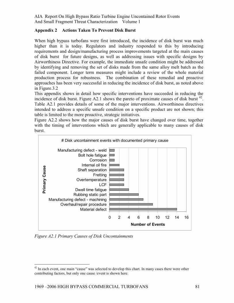
AIA Report On High Bypass Ratio Turbine Engine Uncontained Rotor Events And Small Fragment Threat Characterization Volume 1
1969 –2006 HIGH BYPASS COMMERCIAL TURBOFANS 81
Appendix 2 Actions Taken To Prevent Disk Burst
When high bypass turbofans were first introduced, the incidence of disk burst was much higher than it is today. Regulators and industry responded to this by introducing requirements and design/manufacturing process improvements targeted at the main causes of disk burst for future designs, as well as addressing issues with specific designs by Airworthiness Directive. For example, the immediate unsafe condition might be addressed by identifying and removing the set of disks made from the same alloy melt batch as the failed component. Longer term measures might include a review of the whole material production process for robustness. The combination of these remedial and proactive approaches has been very successful in reducing the incidence of disk burst, as noted above in Figure.3.2 This appendix shows in detail how specific interventions have succeeded in reducing the incidence of disk burst. Figure A2.1 shows the pareto of proximate causes of disk burst 42. Table A2.1 provides details of some of the major interventions. Airworthiness directives intended to address a specific unsafe condition on a specific product are not shown; this table is limited to the more proactive, strategic initiatives. Figure A2.2 shows how the major causes of disk burst have changed over time, together with the timing of interventions which are generally applicable to many causes of disk burst.
Figure A2.1 Primary Causes of Disk Uncontainments
42 In each event, one main “cause” was selected to develop this chart. In many cases there were other contributing factors, but only one cause /event is shown here.
# Disk uncontainment events with documented primary cause
0 2 4 6 8 10 12 14 16
Material defectOverhaul/repair procedure
Manufacturing defect - machiningRubbing static partDwell time fatigue
LCFOvertemperature
FrettingShaft separation
Internal oil fireCorrosion
Bolt hole fatigueManufacturing defect - weld
Prim
ary
Cau
se
Number of Events

AIA Report On High Bypass Ratio Turbine Engine Uncontained Rotor Events And Small Fragment Threat Characterization Volume 1
1969 –2006 HIGH BYPASS COMMERCIAL TURBOFANS 82
Year/Era Milestone Type of change
1960’s – 1970’s Double Vacuum Arc Re-melt (VAR) titanium
Manufacturer-specific actions with respect to internal oil fire
Manufacturer-specific actions with respect to fretting
1970’s Lifing Approach: safe lifing
1974 14 CFR part 33 Section. 33.14 Start-stop cyclic stress (low-cycle fatigue). Required calculation of LCF lives for disks and spacers and publication of life limits.
Regulation
1974 14 CFR part 33 Section 33.27 Turbine, compressor, and turbosupercharger rotors.
Prescribed overspeed testing requirements for rotors with considerable margin beyond maximum operating speeds.
Regulation
1974 14 CFR part 33 Section. 33.62 [Stress analysis.] ������������ �������� �������� ���������� ����������� �� �� �������������� ������������
Regulation
1970’s –1980’s Triple Vacuum Arc Re-melt (VAR) or hearth melt (HM) titanium
Double vacuum art remelt process of titanium alloy replaced by triple vacuum arc remelt. This significantly reduced the oxygen-rich inclusions in the alloy, which had provided sites for crack initiation.
Process
1980’s 3-D stress analysis begins
Approach to Lifing codified.
Lifing Approach: Safe Life + fixed process manufacturing
Production process steps, tools, fixtures, machine code, under change control
Development of Fracture Mechanics discipline
Titanium billet size reduction
Process
1984 Refinements to 14 CFR part 33 Sections 33.94 and 33.27
JAR-E-850 (No hazardous effects from shaft separation)
JAR-E-860 (Analyze loss of cooling to rotors)
Regulation
1988 FAA releases AC 20-128 Design Considerations for Minimizing Hazards Caused by Uncontained Turbine Engine and Auxiliary Power Unit Rotor and Fan Blade Failures
Regulation
1989 Sioux City – Uncontained rotor burst Event
1990 FAA Titanium Rotating Component Review Team Report
“recommended consideration of incorporating risk management and damage tolerance concepts into design procedures for critical, high energy components in commercial engines.”
Standard
1990’s Inspection process improvements – Titanium blue etch inspection Process
1990’s Lifing Approach: Safe Life + fixed process manufacturing + Process validation/monitoring
Validation of manufacturing process, monitoring of power consumption during material removal operations, monitoring of tool force during material operations, monitoring of cooling flow
Process, technique
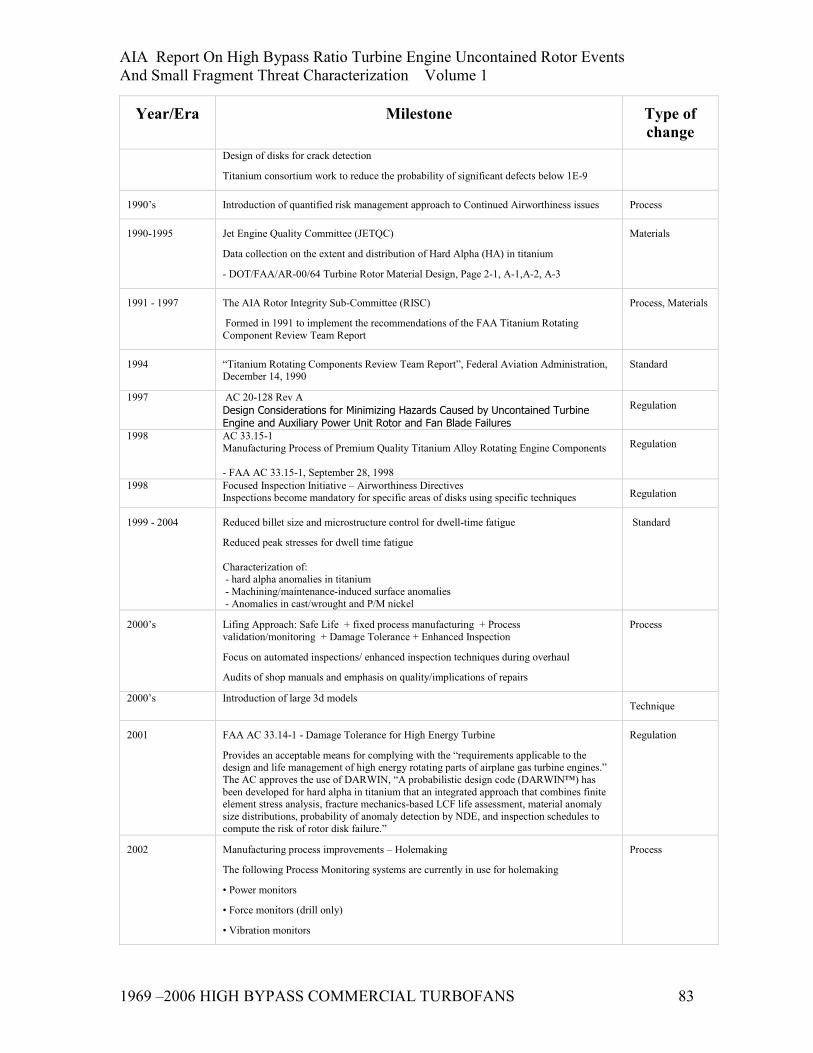
AIA Report On High Bypass Ratio Turbine Engine Uncontained Rotor Events And Small Fragment Threat Characterization Volume 1
1969 –2006 HIGH BYPASS COMMERCIAL TURBOFANS 83
Year/Era Milestone Type of change
Design of disks for crack detection
Titanium consortium work to reduce the probability of significant defects below 1E-9
1990’s Introduction of quantified risk management approach to Continued Airworthiness issues Process
1990-1995 Jet Engine Quality Committee (JETQC)
Data collection on the extent and distribution of Hard Alpha (HA) in titanium
- DOT/FAA/AR-00/64 Turbine Rotor Material Design, Page 2-1, A-1,A-2, A-3
Materials
1991 - 1997 The AIA Rotor Integrity Sub-Committee (RISC)
Formed in 1991 to implement the recommendations of the FAA Titanium Rotating Component Review Team Report
Process, Materials
1994 “Titanium Rotating Components Review Team Report”, Federal Aviation Administration, December 14, 1990
Standard
1997 AC 20-128 Rev A ���� �� �������� ����� ����� � ������������! �� ��� ��"���� �# �� �� �$�%������&����! �������� �'� (����'������
Regulation
1998 AC 33.15-1 Manufacturing Process of Premium Quality Titanium Alloy Rotating Engine Components
- FAA AC 33.15-1, September 28, 1998
Regulation
1998 Focused Inspection Initiative – Airworthiness Directives Inspections become mandatory for specific areas of disks using specific techniques Regulation
1999 - 2004 Reduced billet size and microstructure control for dwell-time fatigue
Reduced peak stresses for dwell time fatigue
Characterization of: - hard alpha anomalies in titanium - Machining/maintenance-induced surface anomalies - Anomalies in cast/wrought and P/M nickel
Standard
2000’s Lifing Approach: Safe Life + fixed process manufacturing + Process validation/monitoring + Damage Tolerance + Enhanced Inspection
Focus on automated inspections/ enhanced inspection techniques during overhaul
Audits of shop manuals and emphasis on quality/implications of repairs
Process
2000’s Introduction of large 3d models Technique
2001 FAA AC 33.14-1 - Damage Tolerance for High Energy Turbine
Provides an acceptable means for complying with the “requirements applicable to the design and life management of high energy rotating parts of airplane gas turbine engines.” The AC approves the use of DARWIN, “A probabilistic design code (DARWIN™) has been developed for hard alpha in titanium that an integrated approach that combines finite element stress analysis, fracture mechanics-based LCF life assessment, material anomaly size distributions, probability of anomaly detection by NDE, and inspection schedules to compute the risk of rotor disk failure.”
Regulation
2002 Manufacturing process improvements – Holemaking
The following Process Monitoring systems are currently in use for holemaking
• Power monitors
• Force monitors (drill only)
• Vibration monitors
Process

AIA Report On High Bypass Ratio Turbine Engine Uncontained Rotor Events And Small Fragment Threat Characterization Volume 1
1969 –2006 HIGH BYPASS COMMERCIAL TURBOFANS 84
Year/Era Milestone Type of change
• Coolant Flow
• Coolant Pressure
• Spindle Speed
• Feedrate
- AIA, Rotor Manufacturing Project (RoMan) Report [draft], Guidelines to Minimize Manufacturing Induced Anomalies in Critical Rotating Parts, March 30, 2002
2002 Manufacturing process improvements – Honing of bore holes Process
2007 14 CFR part 33 Section 33.70 governs machining of holes Regulation
2008 (pending) AC 33.70-X governs machining of holes of critical parts
AC33.70-Y governs machining of other surface features of critical parts
Regulation
Table A2.1 Milestones in Turbine Rotor Integrity Improvements
Figure A2.2 Disk burst causes, by decade
Figures A2.3 through A2.10 separate out the major causes of disk bursts, and show how the cause-specific interventions were successful in reducing the numbers of events and the burst rate. For instance, hard alpha segregate in titanium alloy disks was identified as a source of fatigue cracks in the early 1970s. Prevention began with changes in Ti melting procedures from double-melt to triple-melt, and went on to improved production processes such as improved forging microstructure control and enhanced ultrasonic inspections.
Primary causes of disk uncontainment - by decade
1.00E-09
1.00E-08
1.00E-07
1.00E-06
1970 - 79 1980 - 89 1990 - 99 2000 - 06
Decade in which event occurred
Dis
k un
cont
ainm
ent r
ate,
for a
giv
en c
ause
material defectmachiningoverhaul/repairLCFDwell time fatiguerub static partovertempfrettingshaft sepinternal oil fire
33.62
3D stress analysisSafe Life/ fracture mechanicsAC20-128
Quantified Risk ManagementFocused Inspection Initiative
Large 3D stress modelsDamage tolerance(AC 33.14-1)
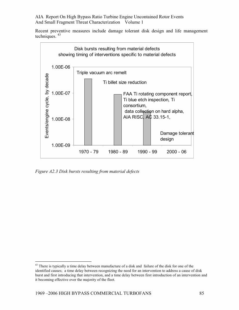
AIA Report On High Bypass Ratio Turbine Engine Uncontained Rotor Events And Small Fragment Threat Characterization Volume 1
1969 –2006 HIGH BYPASS COMMERCIAL TURBOFANS 85
Recent preventive measures include damage tolerant disk design and life management techniques. 43
Figure A2.3 Disk bursts resulting from material defects
43 There is typically a time delay between manufacture of a disk and failure of the disk for one of the identified causes; a time delay between recognizing the need for an intervention to address a cause of disk burst and first introducing that intervention, and a time delay between first introduction of an intervention and it becoming effective over the majority of the fleet.
Disk bursts resulting from material defects showing timing of interventions specific to material defects
1.00E-09
1.00E-08
1.00E-07
1.00E-06
1970 - 79 1980 - 89 1990 - 99 2000 - 06
Even
ts/e
ngin
e cy
cle,
by
deca
de
Triple vacuum arc remelt
Ti billet size reduction
FAA Ti rotating component report, Ti blue etch inspection, Ti consortium, data collection on hard alpha,AIA RISC, AC 33.15-1,
Damage tolerant design
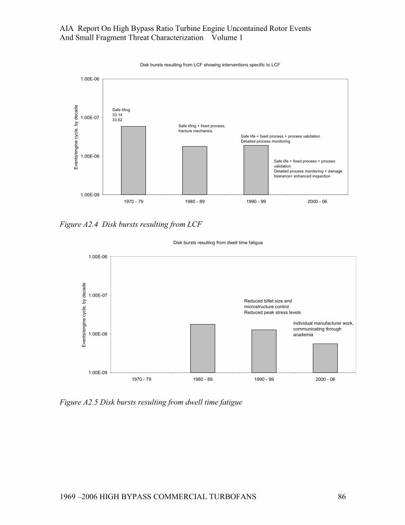
AIA Report On High Bypass Ratio Turbine Engine Uncontained Rotor Events And Small Fragment Threat Characterization Volume 1
1969 –2006 HIGH BYPASS COMMERCIAL TURBOFANS 86
Figure A2.4 Disk bursts resulting from LCF
Figure A2.5 Disk bursts resulting from dwell time fatigue
Disk bursts resulting from LCF showing interventions specific to LCF
1.00E-09
1.00E-08
1.00E-07
1.00E-06
1970 - 79 1980 - 89 1990 - 99 2000 - 06
Eve
nts/
engi
ne c
ycle
, by
deca
de Safe lifing33.1433.62
Safe lifing + fixed process,fracture mechanics
Safe life + fixed process + process validationDetailed process monitoring
Safe life + fixed process + process validationDetailed process monitoring + damage tolerance+ enhanced inspection
Disk bursts resulting from dwell time fatigue
1.00E-09
1.00E-08
1.00E-07
1.00E-06
1970 - 79 1980 - 89 1990 - 99 2000 - 06
Eve
nts/
engi
ne c
ycle
, by
deca
de
Individual manufacturer work, communicating through academia
Reduced billet size and microstructure controlReduced peak stress levels
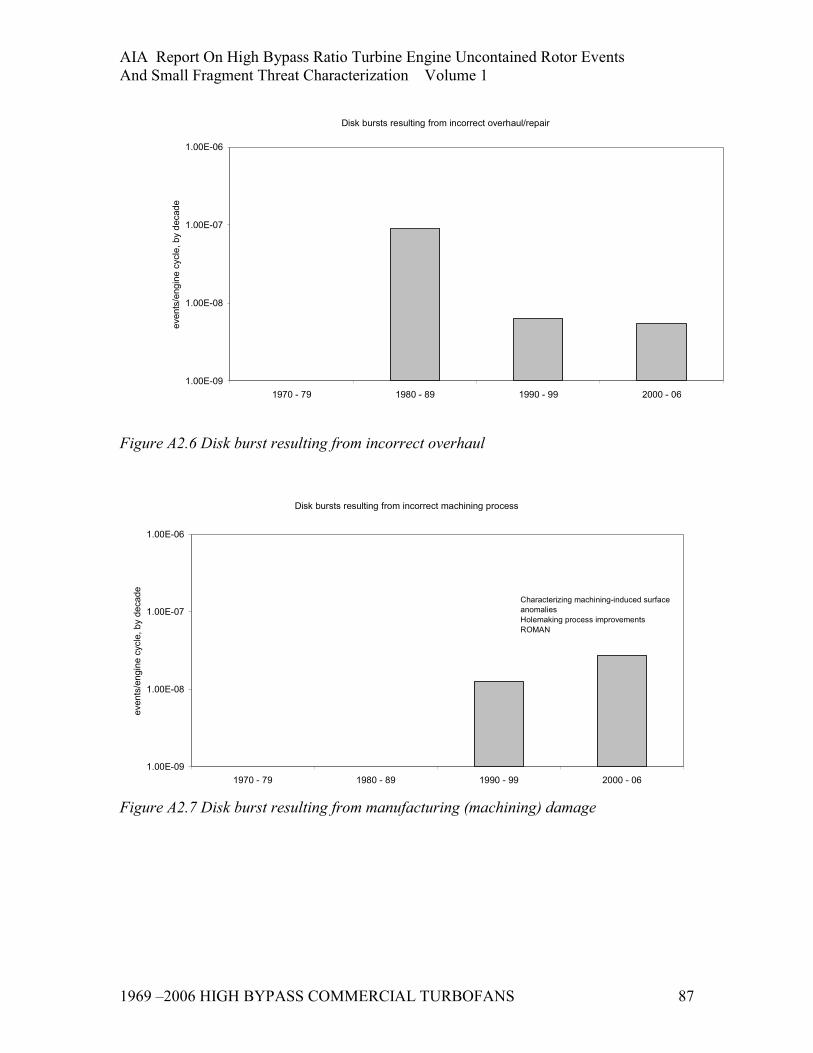
AIA Report On High Bypass Ratio Turbine Engine Uncontained Rotor Events And Small Fragment Threat Characterization Volume 1
1969 –2006 HIGH BYPASS COMMERCIAL TURBOFANS 87
Figure A2.6 Disk burst resulting from incorrect overhaul
Figure A2.7 Disk burst resulting from manufacturing (machining) damage
Disk bursts resulting from incorrect machining process
1.00E-09
1.00E-08
1.00E-07
1.00E-06
1970 - 79 1980 - 89 1990 - 99 2000 - 06
even
ts/e
ngin
e cy
cle,
by
deca
de Characterizing machining-induced surface anomaliesHolemaking process improvementsROMAN
Disk bursts resulting from incorrect overhaul/repair
1.00E-09
1.00E-08
1.00E-07
1.00E-06
1970 - 79 1980 - 89 1990 - 99 2000 - 06
even
ts/e
ngin
e cy
cle,
by
deca
de
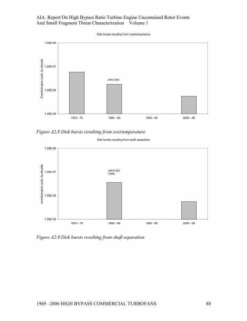
AIA Report On High Bypass Ratio Turbine Engine Uncontained Rotor Events And Small Fragment Threat Characterization Volume 1
1969 –2006 HIGH BYPASS COMMERCIAL TURBOFANS 88
Figure A2.8 Disk bursts resulting from overtemperature
Figure A2.9 Disk bursts resulting from shaft separation
Disk bursts resulting from overtemperature
1.00E-09
1.00E-08
1.00E-07
1.00E-06
1970 - 79 1980 - 89 1990 - 99 2000 - 06
Eve
nts/
engi
ne c
ycle
, by
deca
de
JAR-E-860
Disk bursts resulting from shaft separation
1.00E-09
1.00E-08
1.00E-07
1.00E-06
1970 - 79 1980 - 89 1990 - 99 2000 - 06
even
ts/e
ngin
e cy
cle,
by
deca
de
JAR-E-850 (1986)
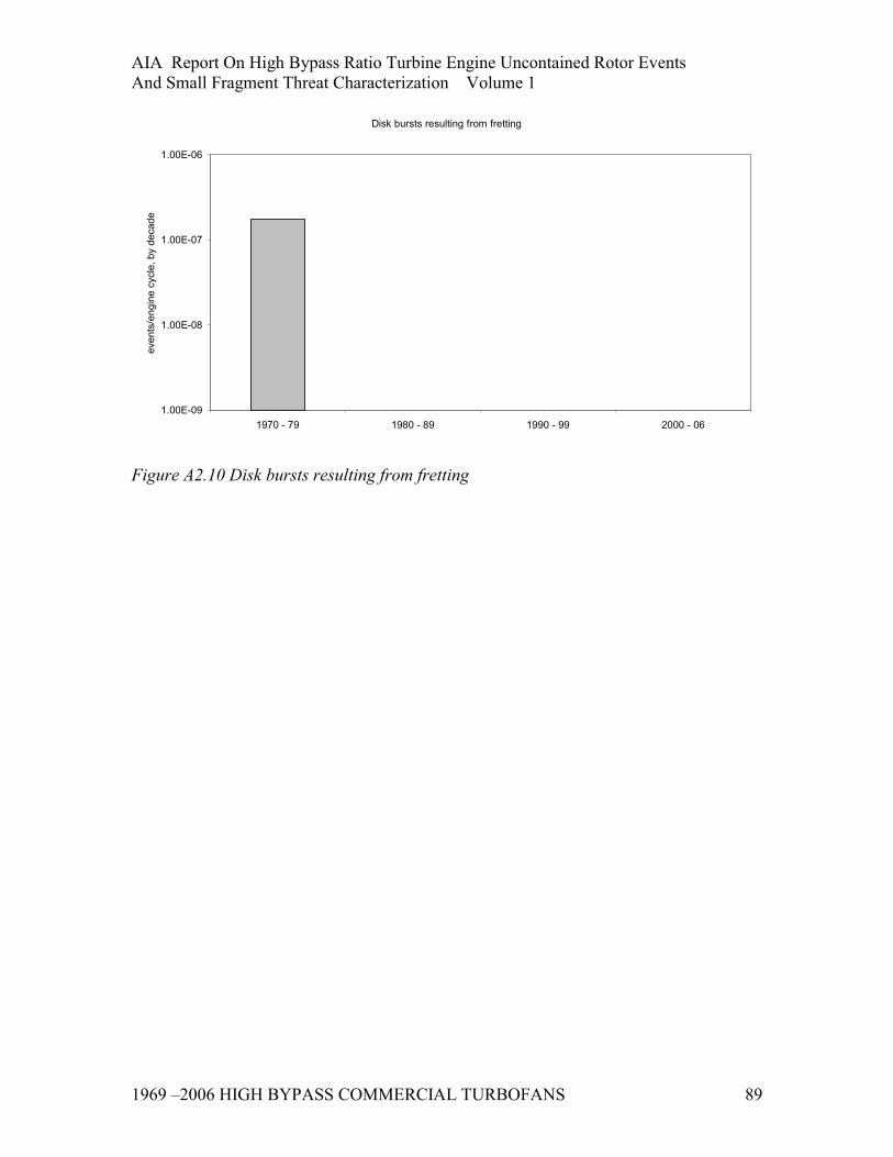
AIA Report On High Bypass Ratio Turbine Engine Uncontained Rotor Events And Small Fragment Threat Characterization Volume 1
1969 –2006 HIGH BYPASS COMMERCIAL TURBOFANS 89
Figure A2.10 Disk bursts resulting from fretting
Disk bursts resulting from fretting
1.00E-09
1.00E-08
1.00E-07
1.00E-06
1970 - 79 1980 - 89 1990 - 99 2000 - 06
even
ts/e
ngin
e cy
cle,
by
deca
de

AIA Report On High Bypass Ratio Turbine Engine Uncontained Rotor Events And Small Fragment Threat Characterization Volume 1
1969 –2006 HIGH BYPASS COMMERCIAL TURBOFANS 90
Appendix 3 Blade Non-Containment
Summary The rate of forward arc non-containment has fallen by over 2 orders of magnitude since the first high bypass turbofans entered service. Recent designs of engines have lower rates than the first generation designs. The airplane consequences of forward arc uncontainment are generally limited to a small number of superficial nicks, dents and holes in aerodynamic surfaces. The holes did not allow fragment pass-through in any skin with ballistic capability better than .04” Al 2024 or the cabin window outer pane.
The rate of casing uncontainment by blades has fallen by a factor of over 50 since the first high bypass turbofans entered service. Recent designs of engines have entered service with lower rates than the original designs. The airplane consequences of casing uncontainment by HP compressor and turbine blades are limited to a small number of superficial nicks, dents and holes in aerodynamic surfaces. In the few events where large areas of the casing had been machined away (e.g. vane spinning) or where large pieces of fan blade have been released, some fragments have had enough energy to penetrate .06 Al airplane skin or windows. The most energetic fan blade fragments have been able to completely penetrate .06 Al airplane pressure skin or airplane windows, turbine blade fragments have not (they were stopped partway through).
Spinner failures which are nacelle uncontained are very rare. Airplane damage has generally been limited to nicks and dents, in the study period.
Tailpipe debris usually has insufficient energy to leave a witness mark on the airplane. In those cases with witness marks, the damage has been limited to small holes and dents in aerodynamic surfaces. The debris did not hole and pass through any surfaces with greater ballistic capability than non-metallic honeycomb sandwich, and did not present a hazard to structures or systems.
A3.1 Introduction The focus of this report has been primarily on the fragments resulting from disk burst, since disk bursts have shown themselves to result in more severe events than other rotating parts. This appendix reviews the non-containment of blades and other small debris, in events where the disks remained intact and in place44. For brevity, this is called “blade” non-containment, but other small debris such as a disk post, vanes and associated
44 A small number of events are difficult to categorize as disk vs. blade. For instance, there was an event where fan blade failure led to extreme unbalance and the separation of the entire fan disk, in one piece. This event was addressed in the “blade failure ” appendix, even though the disk itself did not stay in place. The number of these ambiguous events is very low and would not affect the event rates for either disk events or blade events.
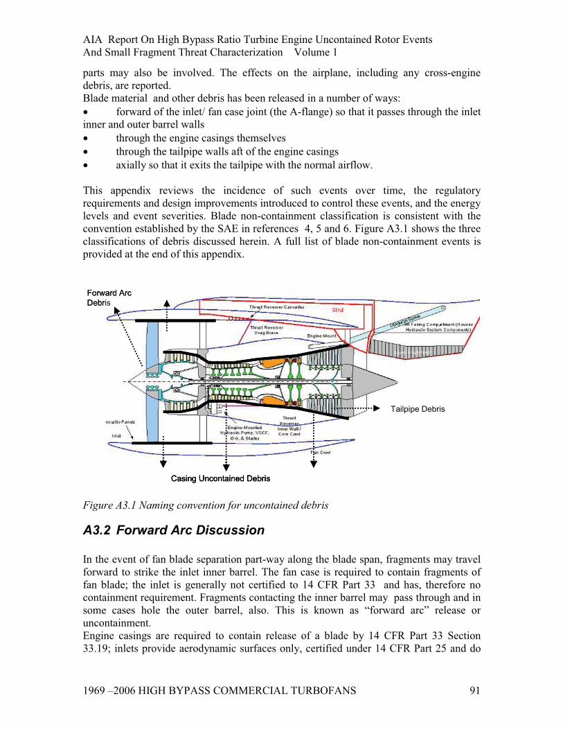
AIA Report On High Bypass Ratio Turbine Engine Uncontained Rotor Events And Small Fragment Threat Characterization Volume 1
1969 –2006 HIGH BYPASS COMMERCIAL TURBOFANS 91
parts may also be involved. The effects on the airplane, including any cross-engine debris, are reported. Blade material and other debris has been released in a number of ways: �� forward of the inlet/ fan case joint (the A-flange) so that it passes through the inlet inner and outer barrel walls �� through the engine casings themselves �� through the tailpipe walls aft of the engine casings �� axially so that it exits the tailpipe with the normal airflow.
This appendix reviews the incidence of such events over time, the regulatory requirements and design improvements introduced to control these events, and the energy levels and event severities. Blade non-containment classification is consistent with the convention established by the SAE in references 4, 5 and 6. Figure A3.1 shows the three classifications of debris discussed herein. A full list of blade non-containment events is provided at the end of this appendix.
Figure A3.1 Naming convention for uncontained debris
A3.2 Forward Arc Discussion
In the event of fan blade separation part-way along the blade span, fragments may travel forward to strike the inlet inner barrel. The fan case is required to contain fragments of fan blade; the inlet is generally not certified to 14 CFR Part 33 and has, therefore no containment requirement. Fragments contacting the inner barrel may pass through and in some cases hole the outer barrel, also. This is known as “forward arc” release or uncontainment. Engine casings are required to contain release of a blade by 14 CFR Part 33 Section 33.19; inlets provide aerodynamic surfaces only, certified under 14 CFR Part 25 and do
Casing Uncontained Debris
Tailpipe Debris
Forward Arc Debris
Casing Uncontained Debris
Tailpipe Debris
Casing Uncontained Debris
Tailpipe Debris
Forward Arc Debris
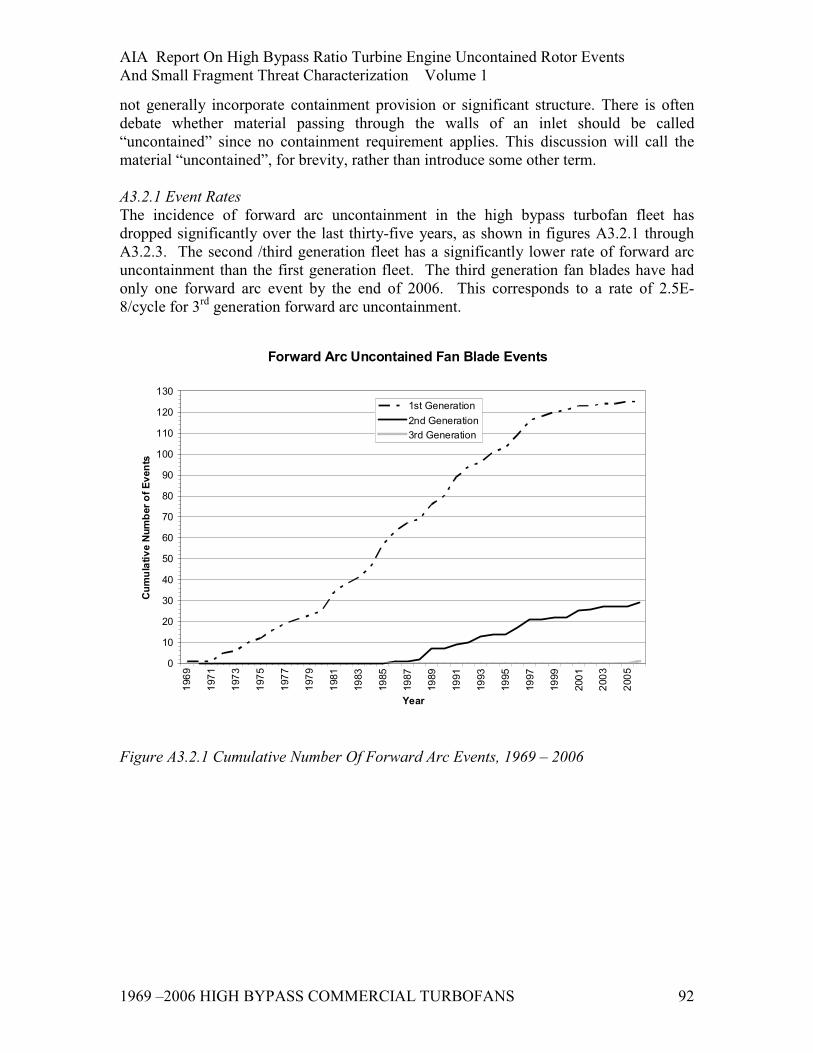
AIA Report On High Bypass Ratio Turbine Engine Uncontained Rotor Events And Small Fragment Threat Characterization Volume 1
1969 –2006 HIGH BYPASS COMMERCIAL TURBOFANS 92
not generally incorporate containment provision or significant structure. There is often debate whether material passing through the walls of an inlet should be called “uncontained” since no containment requirement applies. This discussion will call the material “uncontained”, for brevity, rather than introduce some other term.
A3.2.1 Event Rates The incidence of forward arc uncontainment in the high bypass turbofan fleet has dropped significantly over the last thirty-five years, as shown in figures A3.2.1 through A3.2.3. The second /third generation fleet has a significantly lower rate of forward arc uncontainment than the first generation fleet. The third generation fan blades have had only one forward arc event by the end of 2006. This corresponds to a rate of 2.5E-8/cycle for 3rd generation forward arc uncontainment.
Figure A3.2.1 Cumulative Number Of Forward Arc Events, 1969 – 2006
Forward Arc Uncontained Fan Blade Events
0
10
20
30
40
50
60
70
80
90
100
110
120
130
1969
1971
1973
1975
1977
1979
1981
1983
1985
1987
1989
1991
1993
1995
1997
1999
2001
2003
2005
Year
Cum
ulat
ive
Num
ber o
f Eve
nts
1st Generation2nd Generation3rd Generation

AIA Report On High Bypass Ratio Turbine Engine Uncontained Rotor Events And Small Fragment Threat Characterization Volume 1
1969 –2006 HIGH BYPASS COMMERCIAL TURBOFANS 93
Figure A3.2.2 Forward Arc Event Rates, 1969 – 2006
Figure A3.2.3 Annual number of forward arc events
Forward Arc Uncontained Fan Blade Annual & Trend Rates
1.0E-09
1.0E-08
1.0E-07
1.0E-06
1.0E-05
1.0E-04
1.0E-0319
69
1971
1973
1975
1977
1979
1981
1983
1985
1987
1989
1991
1993
1995
1997
1999
2001
2003
2005
Year
Rat
e Pe
r Eng
ine
Cyc
le
Total Fleet2nd Generation1st Generation3rd Generation5 year rolling average rate (Total Fleet)5 year rolling average rate (2nd & 3rd Generation)5 year rolling average rate (1st Generation)
Forward Arc Uncontained Fan Blade Annual Events
0
1
2
3
4
5
6
7
8
9
10
11
12
1969
1970
1971
1972
1973
1974
1975
1976
1977
1978
1979
1980
1981
1982
1983
1984
1985
1986
1987
1988
1989
1990
1991
1992
1993
1994
1995
1996
1997
1998
1999
2000
2001
2002
2003
2004
2005
2006
Year
Cum
ulat
ive
Num
ber o
f Eve
nts
1st Generation2nd Generation3rd Generation
AIA Report On High Bypass Ratio Turbine Engine Uncontained Rotor Events And Small Fragment Threat Characterization Volume 1
1969 –2006 HIGH BYPASS COMMERCIAL TURBOFANS 94
A3.2.2 Discussion Of Rates The rate of fan forward arc uncontainment has fallen by a factor of more than a thousand since 1970, as shown in A3.2.2. The number of events per year is also much lower than in previous decades, as shown in A3.2.3. The initial high incidence of forward arc uncontainment was driven by birdstrike to the fan, release of fan blade tip fragments and forward travel of the resulting debris45.
Low bypass turbofans had typically had much smaller inlet areas, and also had static Inlet Guide Vanes forward of the fan which broke up and slowed incoming material before it hit the fan. The low bypass experience did not read across into the high bypass fleet, and the incidence of fan blade part-span separation caused by bird ingestion and other FOD was relatively high. The resulting redesigns led to the observed rapid drop in the forward arc rate over the early 1970s.
Engine certification regulations have evolved since that time to require progressive improvements in ingestion capability; Table46 A3.1 documents some of the more notable regulatory interventions (many of which were pre-implemented by issue paper) and technology improvements.
45 This study did not collect data on the causes of blade failure. Causes of blade failure have been addressed in previous studies; Reference 4, table 8.4 and reference 5, table 6.1-13 confirm that birdstrike and other FOD has been the cause of 70 -80% of fan blade non-containment. 46 The table focuses upon the more proactive, strategic regulations affecting the whole industry, rather than individual Airworthiness Directives addressing a design feature of one engine model.
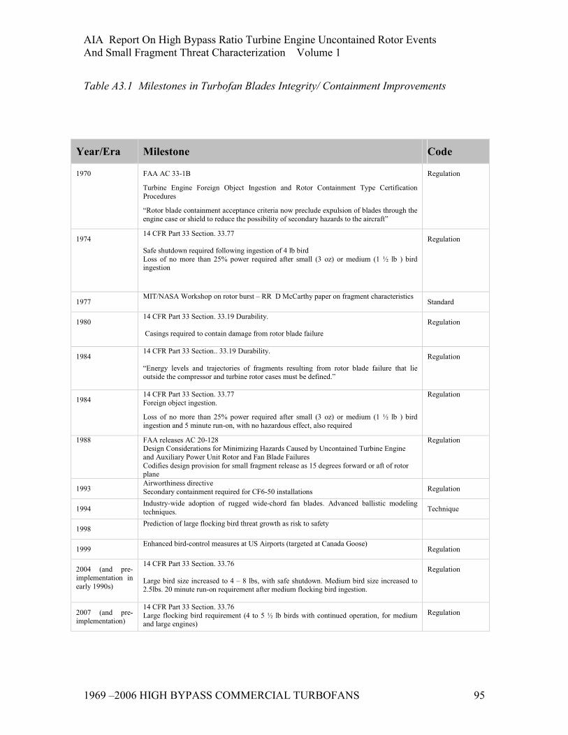
AIA Report On High Bypass Ratio Turbine Engine Uncontained Rotor Events And Small Fragment Threat Characterization Volume 1
1969 –2006 HIGH BYPASS COMMERCIAL TURBOFANS 95
Table A3.1 Milestones in Turbofan Blades Integrity/ Containment Improvements����
Year/Era Milestone Code
1970 FAA AC 33-1B
Turbine Engine Foreign Object Ingestion and Rotor Containment Type Certification Procedures
“Rotor blade containment acceptance criteria now preclude expulsion of blades through the engine case or shield to reduce the possibility of secondary hazards to the aircraft”
Regulation
1974 14 CFR Part 33 Section. 33.77
Safe shutdown required following ingestion of 4 lb bird Loss of no more than 25% power required after small (3 oz) or medium (1 ½ lb ) bird ingestion
Regulation
1977 MIT/NASA Workshop on rotor burst – RR D McCarthy paper on fragment characteristics
Standard
1980 14 CFR Part 33 Section. 33.19 Durability.
Casings required to contain damage from rotor blade failure Regulation
1984 14 CFR Part 33 Section.. 33.19 Durability.
“Energy levels and trajectories of fragments resulting from rotor blade failure that lie outside the compressor and turbine rotor cases must be defined.”
Regulation
1984 14 CFR Part 33 Section. 33.77 Foreign object ingestion.
Loss of no more than 25% power required after small (3 oz) or medium (1 ½ lb ) bird ingestion and 5 minute run-on, with no hazardous effect, also required
Regulation
1988 FAA releases AC 20-128 Design Considerations for Minimizing Hazards Caused by Uncontained Turbine Engine and Auxiliary Power Unit Rotor and Fan Blade Failures Codifies design provision for small fragment release as 15 degrees forward or aft of rotor plane
Regulation
1993 Airworthiness directive Secondary containment required for CF6-50 installations Regulation
1994 Industry-wide adoption of rugged wide-chord fan blades. Advanced ballistic modeling techniques. Technique
1998 Prediction of large flocking bird threat growth as risk to safety
1999 Enhanced bird-control measures at US Airports (targeted at Canada Goose)
Regulation
2004 (and pre-implementation in early 1990s)
14 CFR Part 33 Section. 33.76
Large bird size increased to 4 – 8 lbs, with safe shutdown. Medium bird size increased to 2.5lbs. 20 minute run-on requirement after medium flocking bird ingestion.
Regulation
2007 (and pre-implementation)
14 CFR Part 33 Section. 33.76 Large flocking bird requirement (4 to 5 ½ lb birds with continued operation, for medium and large engines)
Regulation
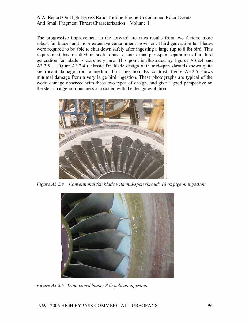
AIA Report On High Bypass Ratio Turbine Engine Uncontained Rotor Events And Small Fragment Threat Characterization Volume 1
1969 –2006 HIGH BYPASS COMMERCIAL TURBOFANS 96
The progressive improvement in the forward arc rates results from two factors; more robust fan blades and more extensive containment provision. Third generation fan blades were required to be able to shut down safely after ingesting a large (up to 8 lb) bird. This requirement has resulted in such robust designs that part-span separation of a third generation fan blade is extremely rare. This point is illustrated by figures A3.2.4 and A3.2.5 . Figure A3.2.4 ( classic fan blade design with mid-span shroud) shows quite significant damage from a medium bird ingestion. By contrast, figure A3.2.5 shows minimal damage from a very large bird ingestion. These photographs are typical of the worst damage observed with these two types of design, and give a good perspective on the step-change in robustness associated with the design evolution.
Figure A3.2.4 Conventional fan blade with mid-span shroud; 18 oz pigeon ingestion
Figure A3.2.5 Wide-chord blade; 8 lb pelican ingestion
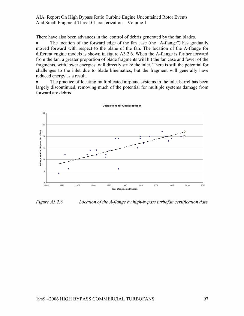
AIA Report On High Bypass Ratio Turbine Engine Uncontained Rotor Events And Small Fragment Threat Characterization Volume 1
1969 –2006 HIGH BYPASS COMMERCIAL TURBOFANS 97
There have also been advances in the control of debris generated by the fan blades. �� The location of the forward edge of the fan case (the “A-flange”) has gradually moved forward with respect to the plane of the fan. The location of the A-flange for different engine models is shown in figure A3.2.6. When the A-flange is further forward from the fan, a greater proportion of blade fragments will hit the fan case and fewer of the fragments, with lower energies, will directly strike the inlet. There is still the potential for challenges to the inlet due to blade kinematics, but the fragment will generally have reduced energy as a result. �� The practice of locating multiplicated airplane systems in the inlet barrel has been largely discontinued, removing much of the potential for multiple systems damage from forward arc debris.
Figure A3.2.6 Location of the A-flange by high-bypass turbofan certification date
Design trend for A-flange location
0
5
10
15
20
25
30
1965 1970 1975 1980 1985 1990 1995 2000 2005 2010 2015
Year of engine certification
A-fl
ange
loca
tion
(deg
rees
fwd
of fa
n)
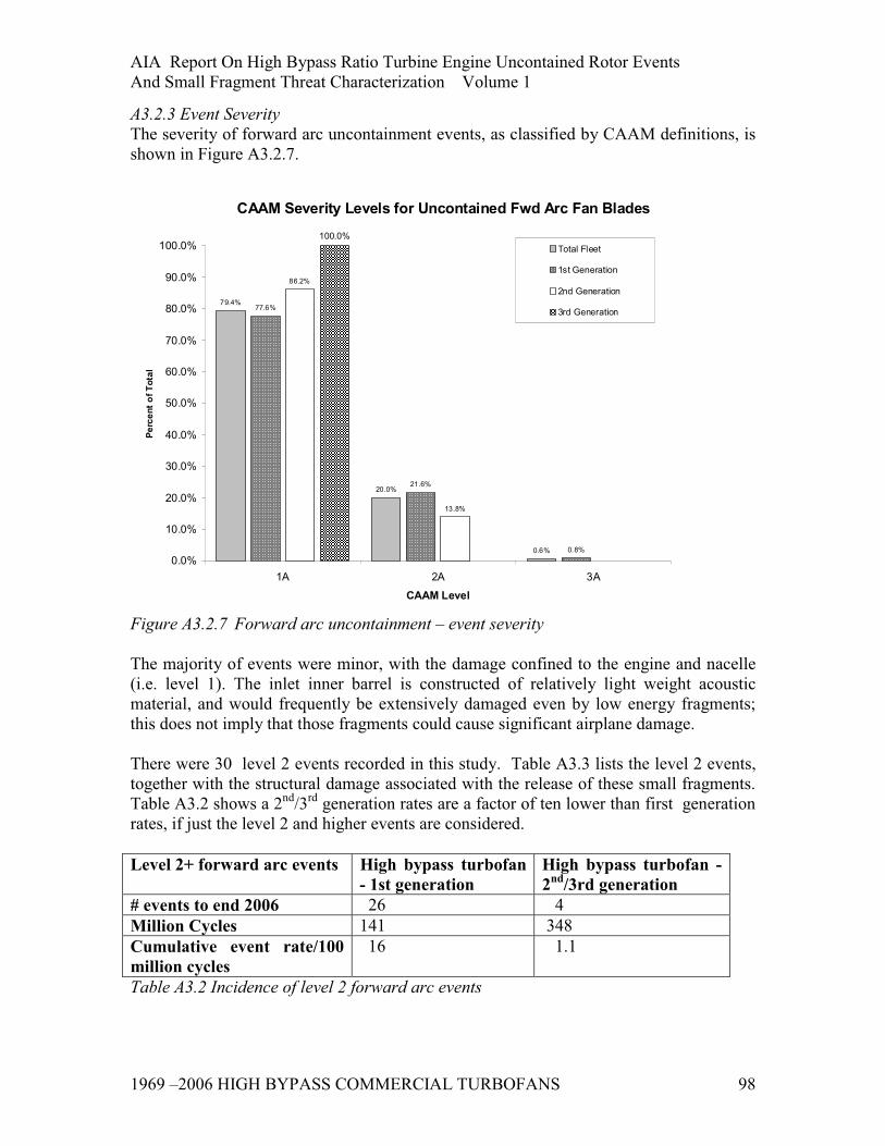
AIA Report On High Bypass Ratio Turbine Engine Uncontained Rotor Events And Small Fragment Threat Characterization Volume 1
1969 –2006 HIGH BYPASS COMMERCIAL TURBOFANS 98
A3.2.3 Event Severity The severity of forward arc uncontainment events, as classified by CAAM definitions, is shown in Figure A3.2.7.
Figure A3.2.7 Forward arc uncontainment – event severity
The majority of events were minor, with the damage confined to the engine and nacelle (i.e. level 1). The inlet inner barrel is constructed of relatively light weight acoustic material, and would frequently be extensively damaged even by low energy fragments; this does not imply that those fragments could cause significant airplane damage.
There were 30 level 2 events recorded in this study. Table A3.3 lists the level 2 events, together with the structural damage associated with the release of these small fragments. Table A3.2 shows a 2nd/3rd generation rates are a factor of ten lower than first generation rates, if just the level 2 and higher events are considered.
Level 2+ forward arc events High bypass turbofan - 1st generation
High bypass turbofan - 2nd/3rd generation
# events to end 2006 26 4 Million Cycles 141 348 Cumulative event rate/100 million cycles
16 1.1
Table A3.2 Incidence of level 2 forward arc events
CAAM Severity Levels for Uncontained Fwd Arc Fan Blades
79.4%
20.0%
0.6%
77.6%
21.6%
0.8%
86.2%
13.8%
100.0%
0.0%
10.0%
20.0%
30.0%
40.0%
50.0%
60.0%
70.0%
80.0%
90.0%
100.0%
1A 2A 3A
CAAM Level
Perc
ent o
f Tot
al
Total Fleet
1st Generation
2nd Generation
3rd Generation

AIA Report On High Bypass Ratio Turbine Engine Uncontained Rotor Events And Small Fragment Threat Characterization Volume 1
1969 –2006 HIGH BYPASS COMMERCIAL TURBOFANS 99
Figures A3.2.8 – A3.2.21 show the airplane damage resulting from the events causing airplane damage (where photographs were available).
The two level 3 events (both first generation engines) are as follows; �� Damage to two separate hydraulic system case drain lines routed on the fan case; the forward arc debris was unrelated to the event severity. �� A fragment from an outboard engine holed the aft strut fairing on the inboard engine, damaging the hydraulic reservoir inside. This caused functional loss of an unrelated hydraulic system. The hole was through an aluminum honeycomb panel with total skin thickness of .032” 2024 aluminum. There was no difficulty in controlling the airplane. This is the only time that the fan blade forward arc debris itself produced a level 3 event.
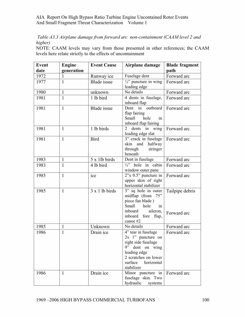
AIA Report On High Bypass Ratio Turbine Engine Uncontained Rotor Events And Small Fragment Threat Characterization Volume 1
1969 –2006 HIGH BYPASS COMMERCIAL TURBOFANS 100
Table A3.3 Airplane damage from forward arc non-containment (CAAM level 2 and higher) NOTE: CAAM levels may vary from those presented in other references; the CAAM levels here relate strictly to the effects of uncontainment
Event date
Engine generation
Event Cause Airplane damage Blade fragment path
1972 1 Runway ice Fuselage dent Forward arc 1977 1 Blade issue ½” puncture in wing
leading edge Forward arc
1980 1 unknown No details Forward arc 1981 1 1 lb bird 4 dents in fuselage,
inboard flap Forward arc
1981 1 Blade issue Dent in outboard flap fairing Small hole in inboard flap fairing
Forward arc
1981 1 1 lb birds 2 dents in wing leading edge slat
Forward arc
1981 1 Bird 3” crack in fuselage skin and halfway through stringer beneath
Forward arc
1983 1 5 x 1lb birds Dent in fuselage Forward arc 1983 1 4 lb bird ½” hole in cabin
window outer pane Forward arc
1985 1 ice 2”x 0.5” puncture in upper skin of right horizontal stabilizer
Forward arc
1985 1 3 x 1 lb birds 3” sq hole in outer midflap (from .75” piece fan blade ) Small hole in inboard aileron, inboard fore flap, canoe #2
Tailpipe debris
Forward arc
1985 1 Unknown No details Forward arc 1986 1 Drain ice 4” tear in fuselage
2x 1” puncture on right side fuselage 9” dent on wing leading edge 2 scratches on lower surface horizontal stabilizer
Forward arc
1986 1 Drain ice Minor puncture in fuselage skin. Two hydraulic systems
Forward arc
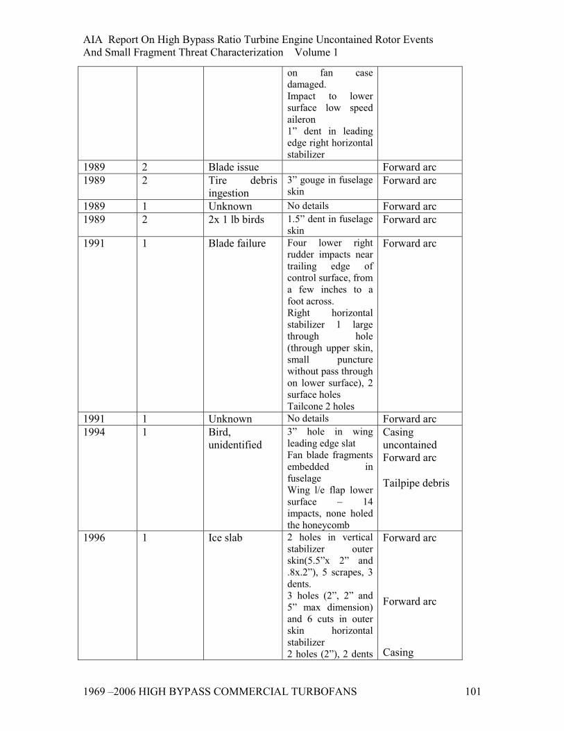
AIA Report On High Bypass Ratio Turbine Engine Uncontained Rotor Events And Small Fragment Threat Characterization Volume 1
1969 –2006 HIGH BYPASS COMMERCIAL TURBOFANS 101
on fan case damaged. Impact to lower surface low speed aileron 1” dent in leading edge right horizontal stabilizer
1989 2 Blade issue Forward arc 1989 2 Tire debris
ingestion 3” gouge in fuselage skin
Forward arc
1989 1 Unknown No details Forward arc 1989 2 2x 1 lb birds 1.5” dent in fuselage
skin Forward arc
1991 1 Blade failure Four lower right rudder impacts near trailing edge of control surface, from a few inches to a foot across. Right horizontal stabilizer 1 large through hole (through upper skin, small puncture without pass through on lower surface), 2 surface holes Tailcone 2 holes
Forward arc
1991 1 Unknown No details Forward arc 1994 1 Bird,
unidentified 3” hole in wing leading edge slat Fan blade fragments embedded in fuselage Wing l/e flap lower surface – 14 impacts, none holed the honeycomb
Casing uncontained Forward arc
Tailpipe debris
1996 1 Ice slab 2 holes in vertical stabilizer outer skin(5.5”x 2” and .8x.2”), 5 scrapes, 3 dents. 3 holes (2”, 2” and 5” max dimension) and 6 cuts in outer skin horizontal stabilizer 2 holes (2”), 2 dents
Forward arc
Forward arc
Casing
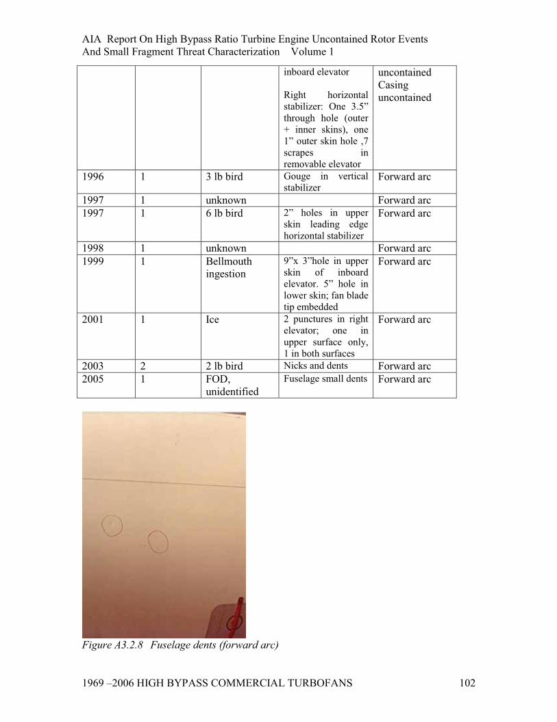
AIA Report On High Bypass Ratio Turbine Engine Uncontained Rotor Events And Small Fragment Threat Characterization Volume 1
1969 –2006 HIGH BYPASS COMMERCIAL TURBOFANS 102
inboard elevator
Right horizontal stabilizer: One 3.5” through hole (outer + inner skins), one 1” outer skin hole ,7 scrapes in removable elevator
uncontained Casing uncontained
1996 1 3 lb bird Gouge in vertical stabilizer
Forward arc
1997 1 unknown Forward arc 1997 1 6 lb bird 2” holes in upper
skin leading edge horizontal stabilizer
Forward arc
1998 1 unknown Forward arc 1999 1 Bellmouth
ingestion 9”x 3”hole in upper skin of inboard elevator. 5” hole in lower skin; fan blade tip embedded
Forward arc
2001 1 Ice 2 punctures in right elevator; one in upper surface only, 1 in both surfaces
Forward arc
2003 2 2 lb bird Nicks and dents Forward arc 2005 1 FOD,
unidentified Fuselage small dents Forward arc
Figure A3.2.8 Fuselage dents (forward arc)
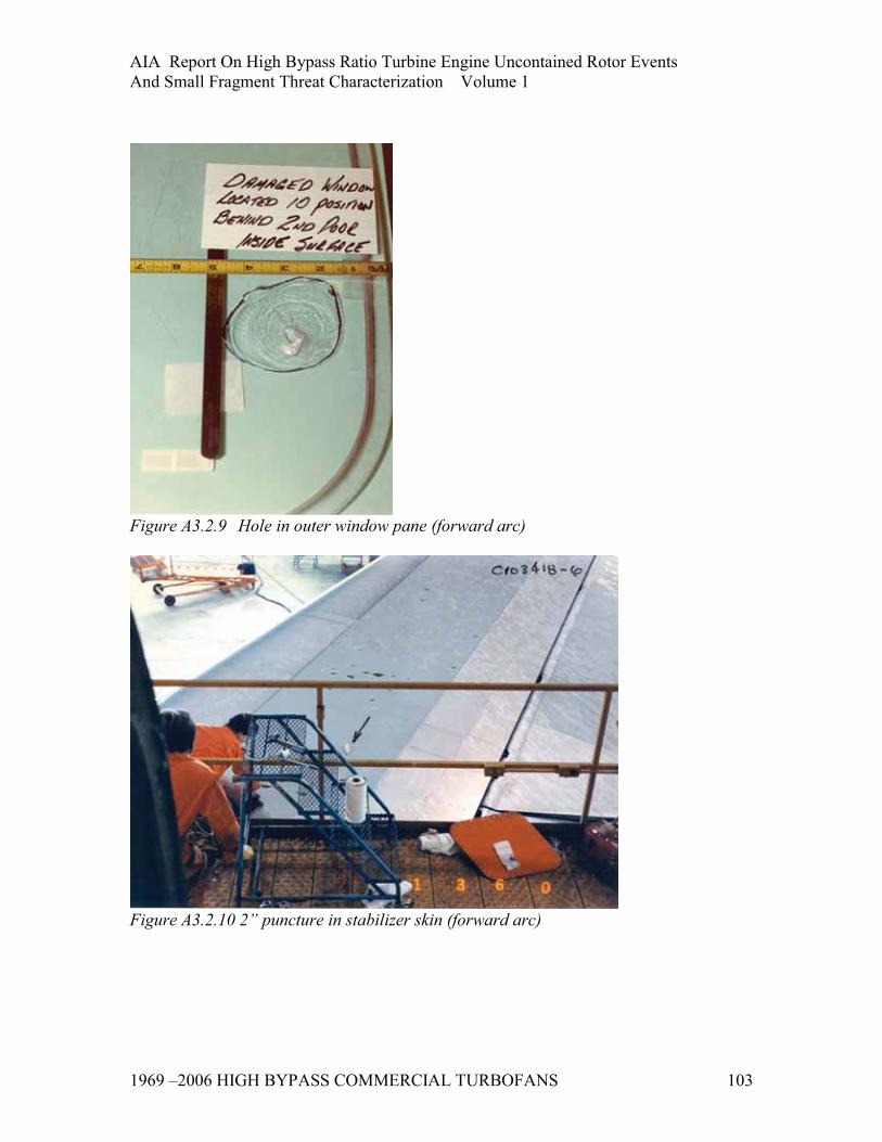
AIA Report On High Bypass Ratio Turbine Engine Uncontained Rotor Events And Small Fragment Threat Characterization Volume 1
1969 –2006 HIGH BYPASS COMMERCIAL TURBOFANS 103
Figure A3.2.9 Hole in outer window pane (forward arc)
Figure A3.2.10 2” puncture in stabilizer skin (forward arc)
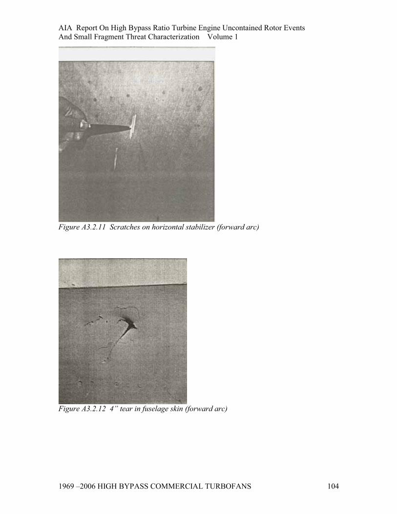
AIA Report On High Bypass Ratio Turbine Engine Uncontained Rotor Events And Small Fragment Threat Characterization Volume 1
1969 –2006 HIGH BYPASS COMMERCIAL TURBOFANS 104
Figure A3.2.11 Scratches on horizontal stabilizer (forward arc)
Figure A3.2.12 4” tear in fuselage skin (forward arc)

AIA Report On High Bypass Ratio Turbine Engine Uncontained Rotor Events And Small Fragment Threat Characterization Volume 1
1969 –2006 HIGH BYPASS COMMERCIAL TURBOFANS 105
Figure A3.2.13 Fuselage skin puncture (forward arc)
Figure A3.2.14 Aileron dent (forward arc)

AIA Report On High Bypass Ratio Turbine Engine Uncontained Rotor Events And Small Fragment Threat Characterization Volume 1
1969 –2006 HIGH BYPASS COMMERCIAL TURBOFANS 106
Figure A3.2.15 3” gouge in fuselage skin (plugged); (forward arc)
Figure A3.2.16 Fuselage patch over puncture (forward arc)
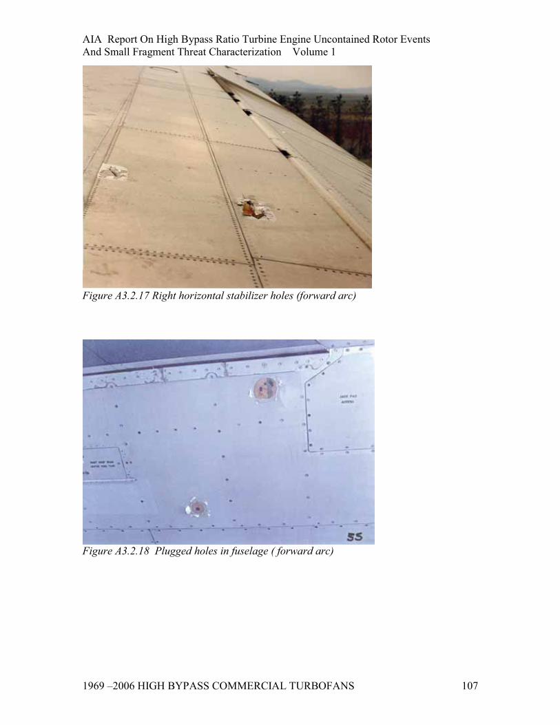
AIA Report On High Bypass Ratio Turbine Engine Uncontained Rotor Events And Small Fragment Threat Characterization Volume 1
1969 –2006 HIGH BYPASS COMMERCIAL TURBOFANS 107
Figure A3.2.17 Right horizontal stabilizer holes (forward arc)
Figure A3.2.18 Plugged holes in fuselage ( forward arc)

AIA Report On High Bypass Ratio Turbine Engine Uncontained Rotor Events And Small Fragment Threat Characterization Volume 1
1969 –2006 HIGH BYPASS COMMERCIAL TURBOFANS 108
Figure A3.2.19 2cm fuselage puncture (forward arc)
Figure A3.2.20 Elevator puncture (forward arc)
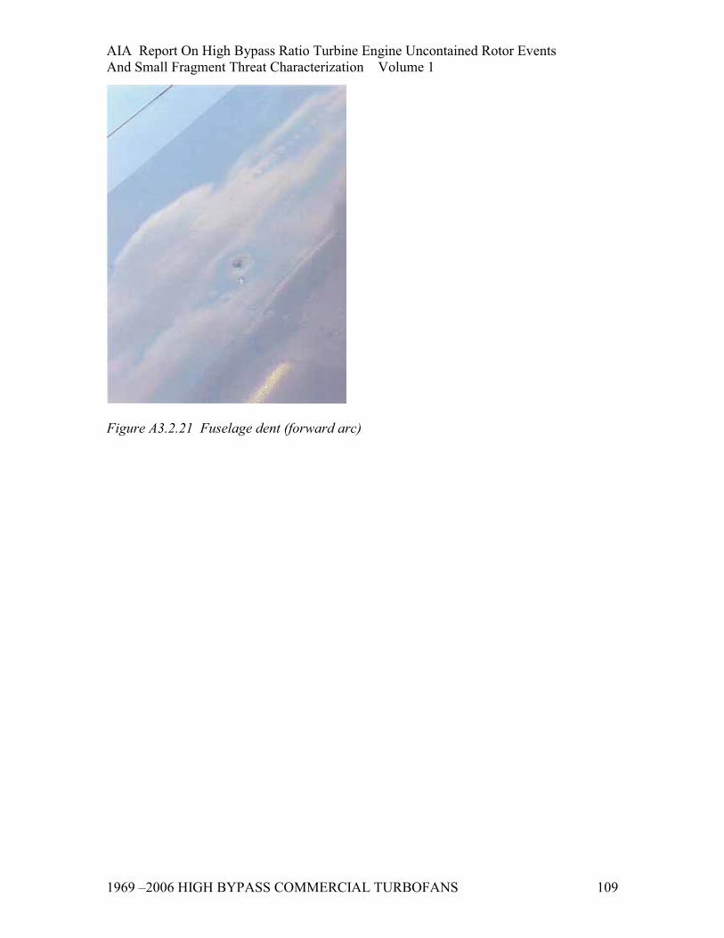
AIA Report On High Bypass Ratio Turbine Engine Uncontained Rotor Events And Small Fragment Threat Characterization Volume 1
1969 –2006 HIGH BYPASS COMMERCIAL TURBOFANS 109
Figure A3.2.21 Fuselage dent (forward arc)
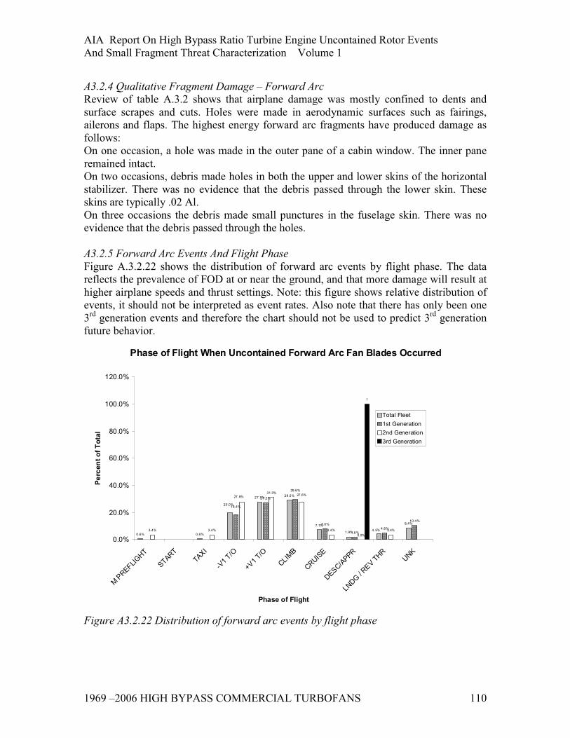
AIA Report On High Bypass Ratio Turbine Engine Uncontained Rotor Events And Small Fragment Threat Characterization Volume 1
1969 –2006 HIGH BYPASS COMMERCIAL TURBOFANS 110
A3.2.4 Qualitative Fragment Damage – Forward Arc Review of table A.3.2 shows that airplane damage was mostly confined to dents and surface scrapes and cuts. Holes were made in aerodynamic surfaces such as fairings, ailerons and flaps. The highest energy forward arc fragments have produced damage as follows: On one occasion, a hole was made in the outer pane of a cabin window. The inner pane remained intact. On two occasions, debris made holes in both the upper and lower skins of the horizontal stabilizer. There was no evidence that the debris passed through the lower skin. These skins are typically .02 Al. On three occasions the debris made small punctures in the fuselage skin. There was no evidence that the debris passed through the holes.
A3.2.5 Forward Arc Events And Flight Phase Figure A.3.2.22 shows the distribution of forward arc events by flight phase. The data reflects the prevalence of FOD at or near the ground, and that more damage will result at higher airplane speeds and thrust settings. Note: this figure shows relative distribution of events, it should not be interpreted as event rates. Also note that there has only been one 3rd generation events and therefore the chart should not be used to predict 3rd generation future behavior.
Figure A3.2.22 Distribution of forward arc events by flight phase
Phase of Flight When Uncontained Forward Arc Fan Blades Occurred
0.6% 0.6%
27.7% 29.0%
7.1%
1.9%
8.4%
27.2%
8.0%
1.6%4.8%
10.4%
3.4% 3.4%
31.0%
3.4%0.0%
3.4%
1
4.5%
20.0%18.4%
29.6%
27.6% 27.6%
0.0%
20.0%
40.0%
60.0%
80.0%
100.0%
120.0%
M PREFLIGHT
STARTTAXI
-V1 T/O
+V1 T
/OCLIM
B
CRUISE
DESC/APPR
LNDG / R
EV THRUNK
Phase of Flight
Perc
ent o
f Tot
al
Total Fleet1st Generation2nd Generation3rd Generation
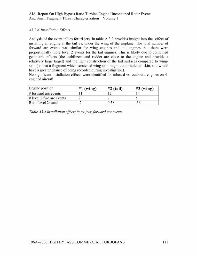
AIA Report On High Bypass Ratio Turbine Engine Uncontained Rotor Events And Small Fragment Threat Characterization Volume 1
1969 –2006 HIGH BYPASS COMMERCIAL TURBOFANS 111
A3.2.6 Installation Effects
Analysis of the event tallies for tri-jets in table A.3.2 provides insight into the effect of installing an engine at the tail vs. under the wing of the airplane. The total number of forward arc events was similar for wing engines and tail engines, but there were proportionally more level 2 events for the tail engines. This is likely due to combined geometric effects (the stabilizers and rudder are close to the engine and provide a relatively large target) and the light construction of the tail surfaces compared to wing-skin (so that a fragment which scratched wing skin might cut or hole tail skin, and would have a greater chance of being recorded during investigation). No significant installation effects were identified for inboard vs. outboard engines on 4-engined aircraft.
Engine position #1 (wing) #2 (tail) #3 (wing) # forward arc events 11 12 14 # level 2 fwd arc events 2 7 5 Ratio level 2: total .2 0.58 .36
Table A3.4 Installation effects in tri-jets; forward arc events
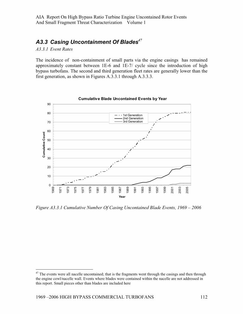
AIA Report On High Bypass Ratio Turbine Engine Uncontained Rotor Events And Small Fragment Threat Characterization Volume 1
1969 –2006 HIGH BYPASS COMMERCIAL TURBOFANS 112
A3.3 Casing Uncontainment Of Blades47
A3.3.1 Event Rates
The incidence of non-containment of small parts via the engine casings has remained approximately constant between 1E-6 and 1E-7/ cycle since the introduction of high bypass turbofans. The second and third generation fleet rates are generally lower than the first generation, as shown in Figures A.3.3.1 through A.3.3.3.
Figure A3.3.1 Cumulative Number Of Casing Uncontained Blade Events, 1969 – 2006
47 The events were all nacelle uncontained; that is the fragments went through the casings and then through the engine cowl/nacelle wall. Events where blades were contained within the nacelle are not addressed in this report. Small pieces other than blades are included here
Cumulative Blade Uncontained Events by Year
0
10
20
30
40
50
60
70
80
90
1969
1971
1973
1975
1977
1979
1981
1983
1985
1987
1989
1991
1993
1995
1997
1999
2001
2003
2005
Year
Cum
ulat
ive
Cou
nt
1st Generation2nd Generation3rd Generation
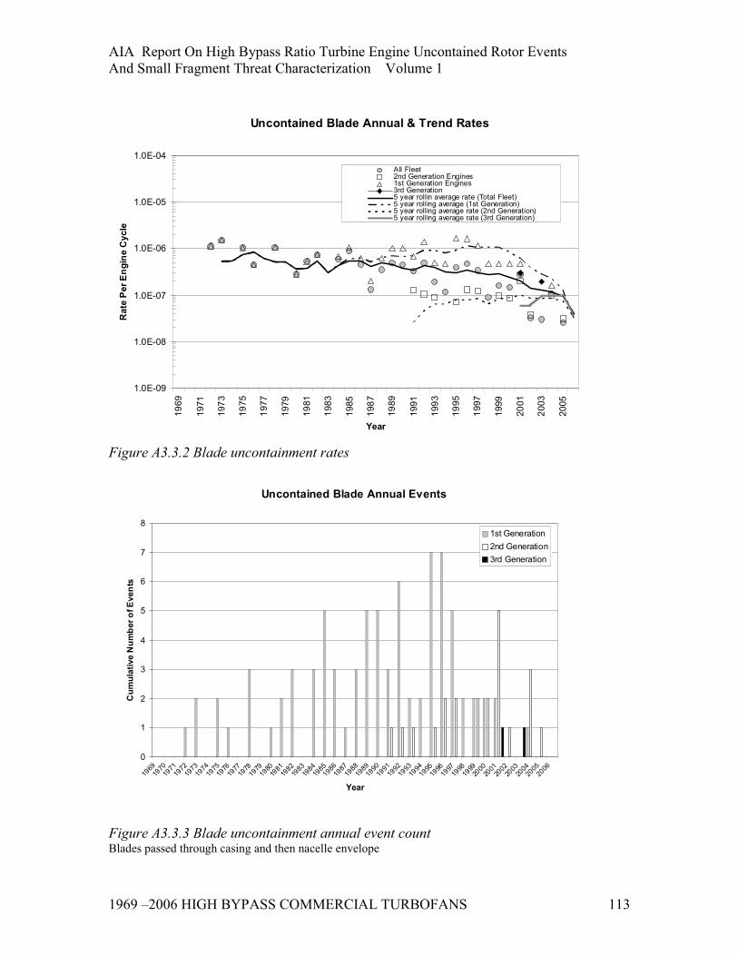
AIA Report On High Bypass Ratio Turbine Engine Uncontained Rotor Events And Small Fragment Threat Characterization Volume 1
1969 –2006 HIGH BYPASS COMMERCIAL TURBOFANS 113
Figure A3.3.2 Blade uncontainment rates
Figure A3.3.3 Blade uncontainment annual event count Blades passed through casing and then nacelle envelope
Uncontained Blade Annual & Trend Rates
1.0E-09
1.0E-08
1.0E-07
1.0E-06
1.0E-05
1.0E-04
1969
1971
1973
1975
1977
1979
1981
1983
1985
1987
1989
1991
1993
1995
1997
1999
2001
2003
2005
Year
Rat
e P
er E
ngin
e C
ycle
All Fleet2nd Generation Engines1st Generation Engines3rd Generation5 year rollin average rate (Total Fleet)5 year rolling average (1st Generation)5 year rolling average rate (2nd Generation)5 year rolling average rate (3rd Generation)
Uncontained Blade Annual Events
0
1
2
3
4
5
6
7
8
1969
1970
1971
1972
1973
1974
1975
1976
1977
1978
1979
1980
1981
1982
1983
1984
1985
1986
1987
1988
1989
1990
1991
1992
1993
1994
1995
1996
1997
1998
1999
2000
2001
2002
2003
2004
2005
2006
Year
Cum
ulat
ive
Num
ber o
f Eve
nts
1st Generation2nd Generation3rd Generation
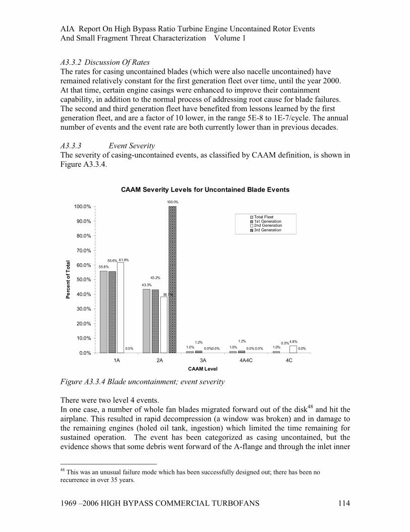
AIA Report On High Bypass Ratio Turbine Engine Uncontained Rotor Events And Small Fragment Threat Characterization Volume 1
1969 –2006 HIGH BYPASS COMMERCIAL TURBOFANS 114
A3.3.2 Discussion Of Rates The rates for casing uncontained blades (which were also nacelle uncontained) have remained relatively constant for the first generation fleet over time, until the year 2000. At that time, certain engine casings were enhanced to improve their containment capability, in addition to the normal process of addressing root cause for blade failures. The second and third generation fleet have benefited from lessons learned by the first generation fleet, and are a factor of 10 lower, in the range 5E-8 to 1E-7/cycle. The annual number of events and the event rate are both currently lower than in previous decades.
A3.3.3 Event Severity The severity of casing-uncontained events, as classified by CAAM definition, is shown in Figure A3.3.4.
Figure A3.3.4 Blade uncontainment; event severity
There were two level 4 events. In one case, a number of whole fan blades migrated forward out of the disk48 and hit the airplane. This resulted in rapid decompression (a window was broken) and in damage to the remaining engines (holed oil tank, ingestion) which limited the time remaining for sustained operation. The event has been categorized as casing uncontained, but the evidence shows that some debris went forward of the A-flange and through the inlet inner
48 This was an unusual failure mode which has been successfully designed out; there has been no recurrence in over 35 years.
CAAM Severity Levels for Uncontained Blade Events
55.8%
43.3%
1.0% 1.0% 1.0%0.0%
4.8%
0.0%
100.0%
0.0% 0.0% 0.0%0.0%1.2%1.2%
55.6%
43.2%
0.0%
38.1%
61.9%
0.0%
10.0%
20.0%
30.0%
40.0%
50.0%
60.0%
70.0%
80.0%
90.0%
100.0%
1A 2A 3A 4A4C 4C
CAAM Level
Perc
ent o
f Tot
al
Total Fleet1st Generation2nd Generation3rd Generation
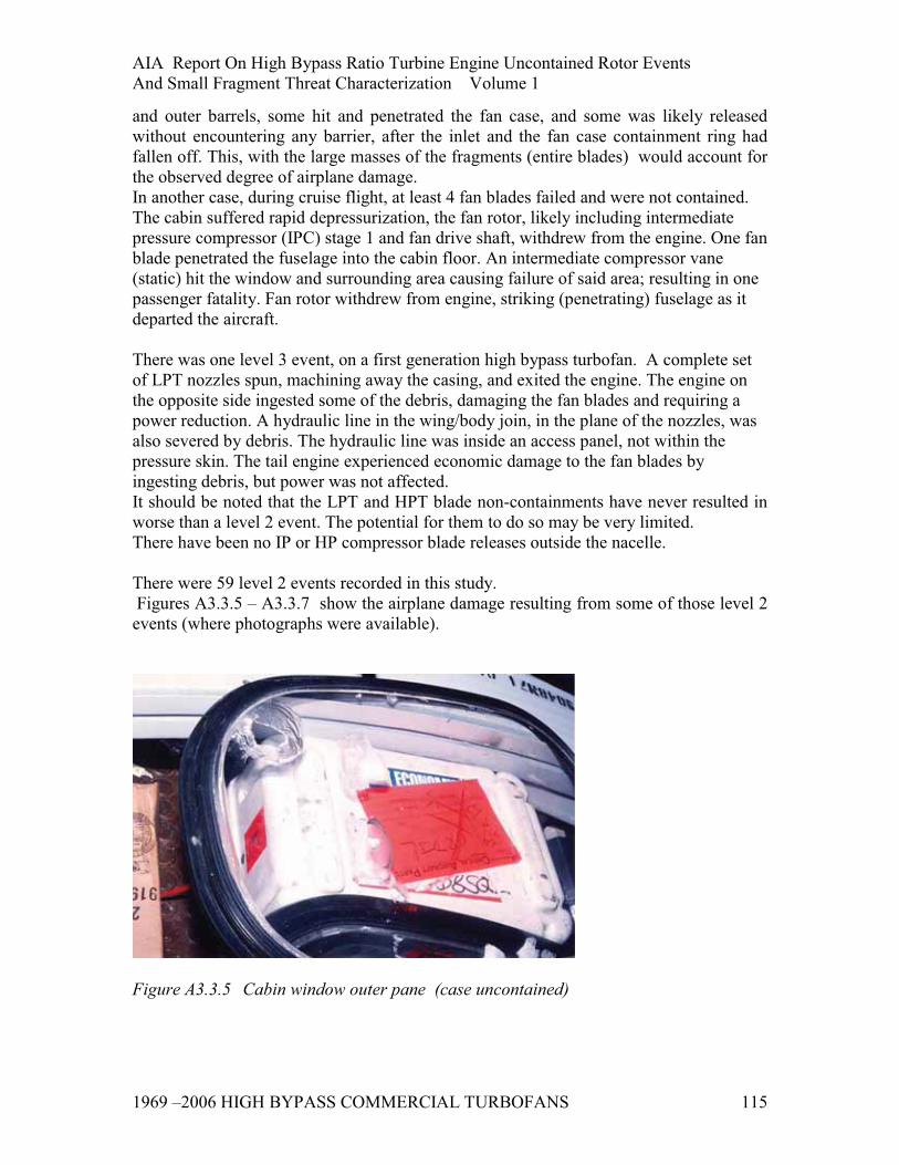
AIA Report On High Bypass Ratio Turbine Engine Uncontained Rotor Events And Small Fragment Threat Characterization Volume 1
1969 –2006 HIGH BYPASS COMMERCIAL TURBOFANS 115
and outer barrels, some hit and penetrated the fan case, and some was likely released without encountering any barrier, after the inlet and the fan case containment ring had fallen off. This, with the large masses of the fragments (entire blades) would account for the observed degree of airplane damage. In another case, during cruise flight, at least 4 fan blades failed and were not contained. The cabin suffered rapid depressurization, the fan rotor, likely including intermediate pressure compressor (IPC) stage 1 and fan drive shaft, withdrew from the engine. One fan blade penetrated the fuselage into the cabin floor. An intermediate compressor vane (static) hit the window and surrounding area causing failure of said area; resulting in one passenger fatality. Fan rotor withdrew from engine, striking (penetrating) fuselage as it departed the aircraft.
There was one level 3 event, on a first generation high bypass turbofan. A complete set of LPT nozzles spun, machining away the casing, and exited the engine. The engine on the opposite side ingested some of the debris, damaging the fan blades and requiring a power reduction. A hydraulic line in the wing/body join, in the plane of the nozzles, was also severed by debris. The hydraulic line was inside an access panel, not within the pressure skin. The tail engine experienced economic damage to the fan blades by ingesting debris, but power was not affected. It should be noted that the LPT and HPT blade non-containments have never resulted in worse than a level 2 event. The potential for them to do so may be very limited. There have been no IP or HP compressor blade releases outside the nacelle.
There were 59 level 2 events recorded in this study. Figures A3.3.5 – A3.3.7 show the airplane damage resulting from some of those level 2 events (where photographs were available).
Figure A3.3.5 Cabin window outer pane (case uncontained)
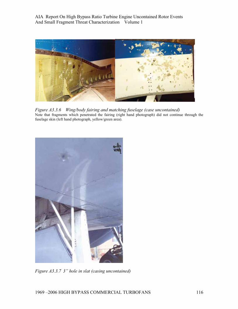
AIA Report On High Bypass Ratio Turbine Engine Uncontained Rotor Events And Small Fragment Threat Characterization Volume 1
1969 –2006 HIGH BYPASS COMMERCIAL TURBOFANS 116
Figure A3.3.6 Wing/body fairing and matching fuselage (case uncontained) Note that fragments which penetrated the fairing (right hand photograph) did not continue through the fuselage skin (left hand photograph, yellow/green area).
Figure A3.3.7 3” hole in slat (casing uncontained)
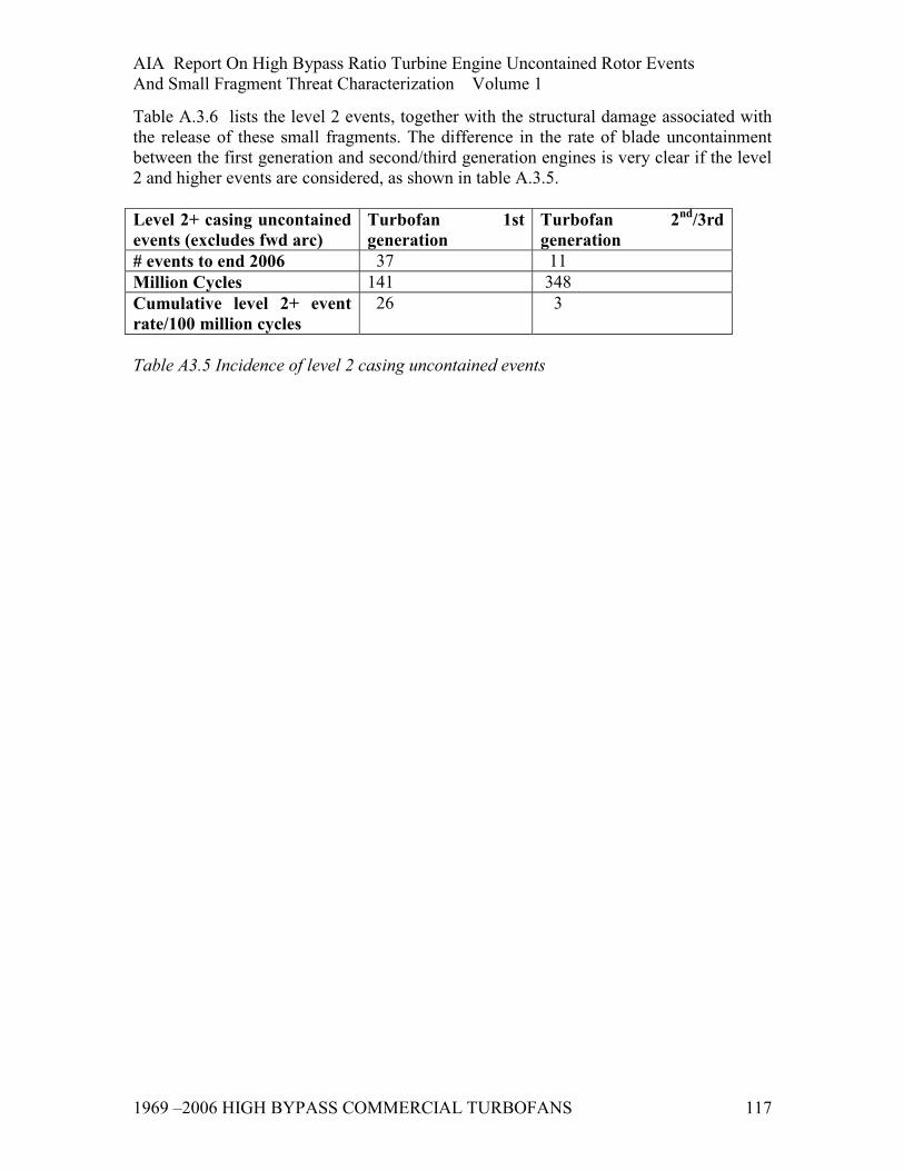
AIA Report On High Bypass Ratio Turbine Engine Uncontained Rotor Events And Small Fragment Threat Characterization Volume 1
1969 –2006 HIGH BYPASS COMMERCIAL TURBOFANS 117
Table A.3.6 lists the level 2 events, together with the structural damage associated with the release of these small fragments. The difference in the rate of blade uncontainment between the first generation and second/third generation engines is very clear if the level 2 and higher events are considered, as shown in table A.3.5. Level 2+ casing uncontained events (excludes fwd arc)
Turbofan 1st generation
Turbofan 2nd/3rd generation
# events to end 2006 37 11 Million Cycles 141 348 Cumulative level 2+ event rate/100 million cycles
26 3
Table A3.5 Incidence of level 2 casing uncontained events
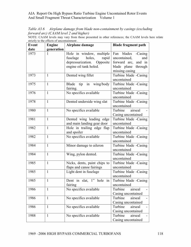
AIA Report On High Bypass Ratio Turbine Engine Uncontained Rotor Events And Small Fragment Threat Characterization Volume 1
1969 –2006 HIGH BYPASS COMMERCIAL TURBOFANS 118
Table A3.6 Airplane damage from blade non-containment by casings (excluding forward arc) (CAAM level 2 and higher) NOTE: CAAM levels may vary from those presented in other references; the CAAM levels here relate strictly to the effects of uncontainment . Event date
Engine generation
Airplane damage Blade fragment path
1973 1 Hole in window, multiple fuselage holes, rapid depressurization. Opposite engine oil tank holed.
Fan blades -Casing uncontained, and forward arc, and in blade plane through missing casing
1973 1 Dented wing fillet Turbine blade -Casing uncontained
1975 1 Blade tip in wing/body fairing.
Turbine blade -Casing uncontained
1976 1 No specifics available Turbine blade -Casing uncontained
1978 1 Dented underside wing slat Turbine blade -Casing uncontained
1980 1 No specifics available Turbine airseal -Casing uncontained
1981 1 Dented wing leading edge and main landing gear door
Turbine blade -Casing uncontained
1982 1 Hole in trailing edge flap and spoiler
Turbine blade -Casing uncontained
1982 1 No specifics available Turbine blade -Casing uncontained
1984 1 Minor damage to aileron Turbine blade -Casing uncontained
1984 1 Wing, pylon dented. Turbine blade -Casing uncontained
1985 1 Nicks, dents, paint chips to flaps and canoe fairings
Turbine blade -Casing uncontained
1985 1 Light dent in fuselage Turbine blade -Casing uncontained
1985 1 Dent in slat, 1” hole in fairing
Turbine blade -Casing uncontained
1986 1 No specifics available Turbine airseal -Casing uncontained
1986 1 No specifics available Turbine airseal -Casing uncontained
1986 1 No specifics available Turbine airseal -Casing uncontained
1988 1 No specifics available Turbine airseal -Casing uncontained
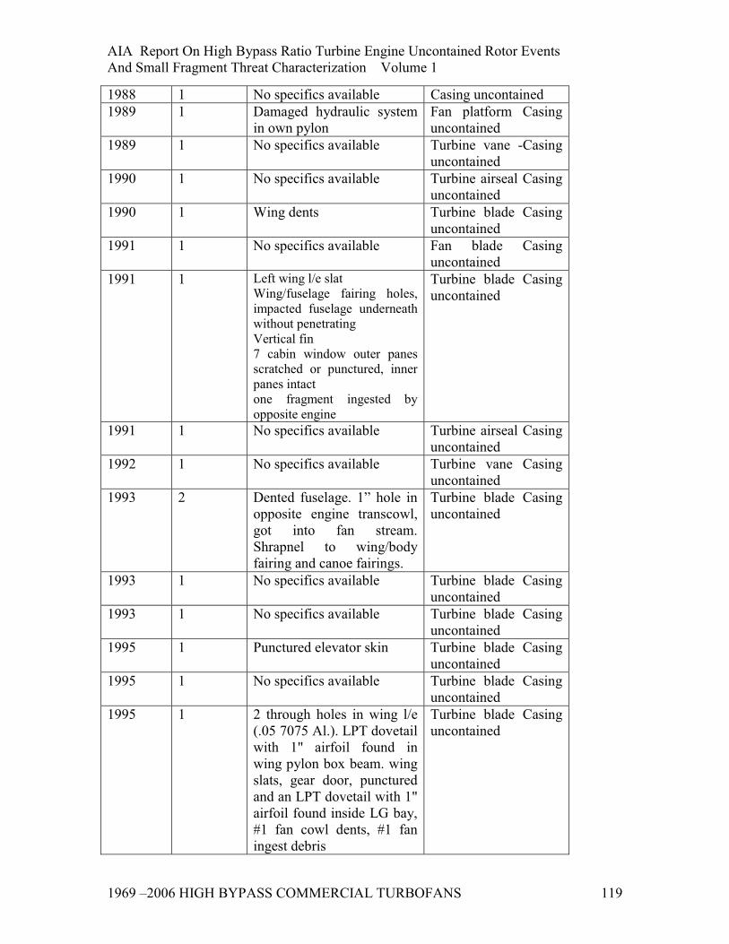
AIA Report On High Bypass Ratio Turbine Engine Uncontained Rotor Events And Small Fragment Threat Characterization Volume 1
1969 –2006 HIGH BYPASS COMMERCIAL TURBOFANS 119
1988 1 No specifics available Casing uncontained 1989 1 Damaged hydraulic system
in own pylon Fan platform Casing uncontained
1989 1 No specifics available Turbine vane -Casing uncontained
1990 1 No specifics available Turbine airseal Casing uncontained
1990 1 Wing dents Turbine blade Casing uncontained
1991 1 No specifics available Fan blade Casing uncontained
1991 1 Left wing l/e slat Wing/fuselage fairing holes, impacted fuselage underneath without penetrating Vertical fin 7 cabin window outer panes scratched or punctured, inner panes intact one fragment ingested by opposite engine
Turbine blade Casing uncontained
1991 1 No specifics available Turbine airseal Casing uncontained
1992 1 No specifics available Turbine vane Casing uncontained
1993 2 Dented fuselage. 1” hole in opposite engine transcowl, got into fan stream. Shrapnel to wing/body fairing and canoe fairings.
Turbine blade Casing uncontained
1993 1 No specifics available Turbine blade Casing uncontained
1993 1 No specifics available Turbine blade Casing uncontained
1995 1 Punctured elevator skin Turbine blade Casing uncontained
1995 1 No specifics available Turbine blade Casing uncontained
1995 1 2 through holes in wing l/e (.05 7075 Al.). LPT dovetail with 1" airfoil found in wing pylon box beam. wing slats, gear door, punctured and an LPT dovetail with 1" airfoil found inside LG bay, #1 fan cowl dents, #1 fan ingest debris
Turbine blade Casing uncontained
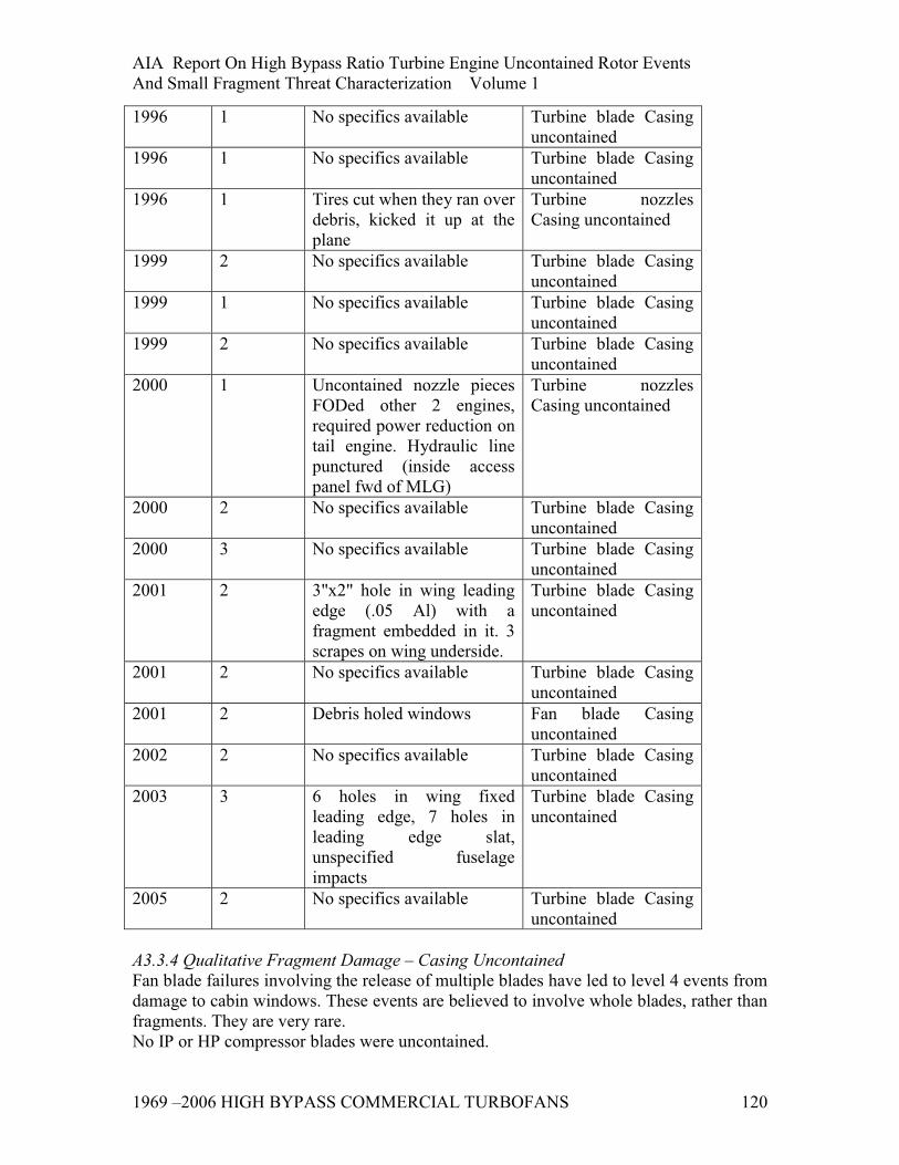
AIA Report On High Bypass Ratio Turbine Engine Uncontained Rotor Events And Small Fragment Threat Characterization Volume 1
1969 –2006 HIGH BYPASS COMMERCIAL TURBOFANS 120
1996 1 No specifics available Turbine blade Casing uncontained
1996 1 No specifics available Turbine blade Casing uncontained
1996 1 Tires cut when they ran over debris, kicked it up at the plane
Turbine nozzles Casing uncontained
1999 2 No specifics available Turbine blade Casing uncontained
1999 1 No specifics available Turbine blade Casing uncontained
1999 2 No specifics available Turbine blade Casing uncontained
2000 1 Uncontained nozzle pieces FODed other 2 engines, required power reduction on tail engine. Hydraulic line punctured (inside access panel fwd of MLG)
Turbine nozzles Casing uncontained
2000 2 No specifics available Turbine blade Casing uncontained
2000 3 No specifics available Turbine blade Casing uncontained
2001 2 3"x2" hole in wing leading edge (.05 Al) with a fragment embedded in it. 3 scrapes on wing underside.
Turbine blade Casing uncontained
2001 2 No specifics available Turbine blade Casing uncontained
2001 2 Debris holed windows Fan blade Casing uncontained
2002 2 No specifics available Turbine blade Casing uncontained
2003 3 6 holes in wing fixed leading edge, 7 holes in leading edge slat, unspecified fuselage impacts
Turbine blade Casing uncontained
2005 2 No specifics available Turbine blade Casing uncontained
A3.3.4 Qualitative Fragment Damage – Casing Uncontained Fan blade failures involving the release of multiple blades have led to level 4 events from damage to cabin windows. These events are believed to involve whole blades, rather than fragments. They are very rare. No IP or HP compressor blades were uncontained.
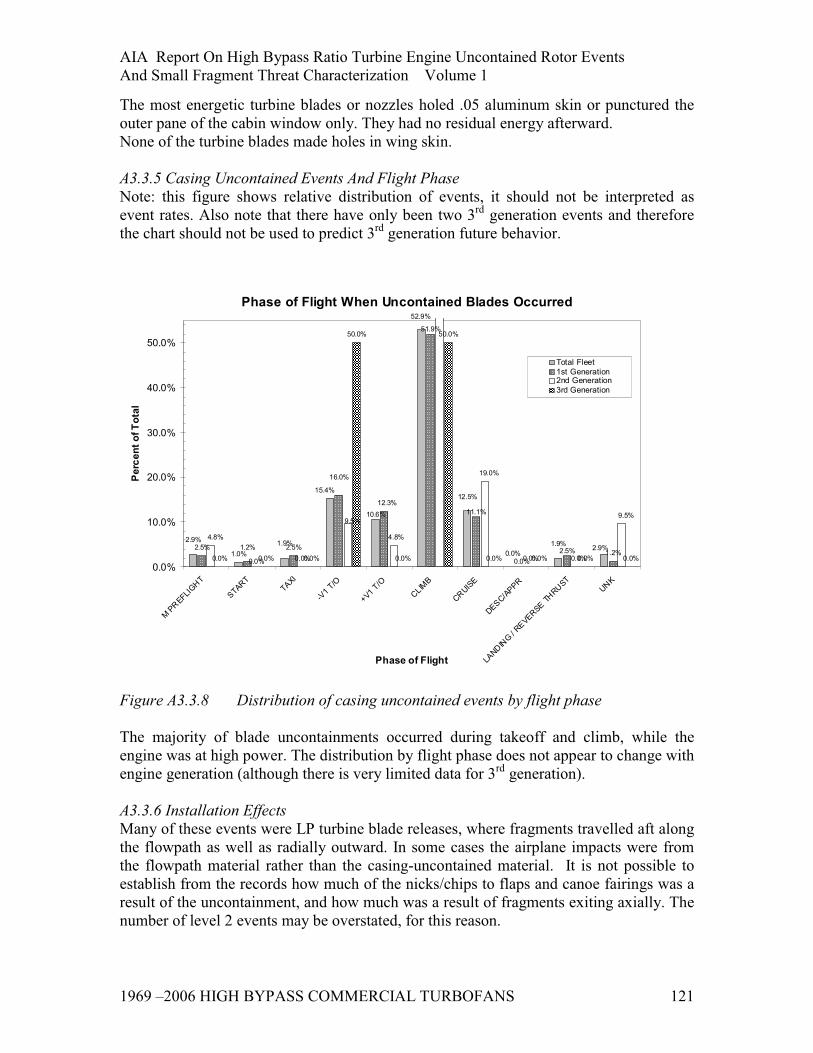
AIA Report On High Bypass Ratio Turbine Engine Uncontained Rotor Events And Small Fragment Threat Characterization Volume 1
1969 –2006 HIGH BYPASS COMMERCIAL TURBOFANS 121
The most energetic turbine blades or nozzles holed .05 aluminum skin or punctured the outer pane of the cabin window only. They had no residual energy afterward. None of the turbine blades made holes in wing skin.
A3.3.5 Casing Uncontained Events And Flight Phase Note: this figure shows relative distribution of events, it should not be interpreted as event rates. Also note that there have only been two 3rd generation events and therefore the chart should not be used to predict 3rd generation future behavior.
Figure A3.3.8 Distribution of casing uncontained events by flight phase
The majority of blade uncontainments occurred during takeoff and climb, while the engine was at high power. The distribution by flight phase does not appear to change with engine generation (although there is very limited data for 3rd generation).
A3.3.6 Installation Effects Many of these events were LP turbine blade releases, where fragments travelled aft along the flowpath as well as radially outward. In some cases the airplane impacts were from the flowpath material rather than the casing-uncontained material. It is not possible to establish from the records how much of the nicks/chips to flaps and canoe fairings was a result of the uncontainment, and how much was a result of fragments exiting axially. The number of level 2 events may be overstated, for this reason.
Phase of Flight When Uncontained Blades Occurred
1.0%2.5% 2.5%
1.2%0.0% 0.0%0.0% 0.0%
50.0%
0.0%
50.0%
0.0% 0.0% 0.0% 0.0%
2.9% 1.9%
15.4%
10.6%
52.9%
2.9%1.9%0.0%
12.5%
1.2%
16.0%
12.3%
2.5%0.0%
11.1%
51.9%
4.8%
0.0%
9.5%
4.8%
19.0%
9.5%
0.0%0.0%0.0%
10.0%
20.0%
30.0%
40.0%
50.0%
M PREFLIGHT
STARTTAXI
-V1 T
/O
+V1 T/OCLIM
B
CRUISE
DESC/APPR
LANDIN
G / REVERSE TH
RUSTUNK
Phase of Flight
Per
cent
of T
otal
Total Fleet1st Generation2nd Generation3rd Generation
AIA Report On High Bypass Ratio Turbine Engine Uncontained Rotor Events And Small Fragment Threat Characterization Volume 1
1969 –2006 HIGH BYPASS COMMERCIAL TURBOFANS 122
Comparison of the ratio of level 2 to total events for wing and tail installations for tri-jets supports this proposition. 30% of casing uncontained events were level 2 or higher for tail installations, where material exiting the tailpipe would not strike the airplane. By contrast, 60% of casing uncontained events were level 2 or higher for wing installations, where material exiting the tailpipe could strike flaps and canoe fairings.
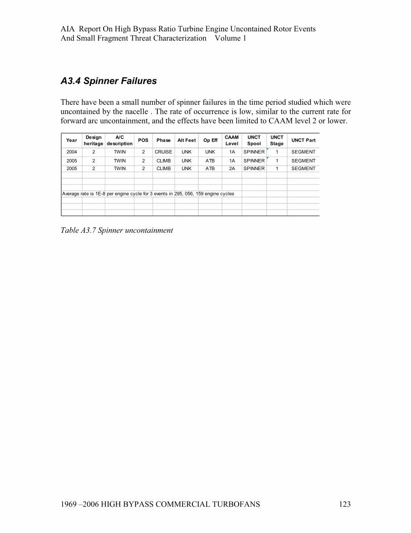
AIA Report On High Bypass Ratio Turbine Engine Uncontained Rotor Events And Small Fragment Threat Characterization Volume 1
1969 –2006 HIGH BYPASS COMMERCIAL TURBOFANS 123
A3.4 Spinner Failures
There have been a small number of spinner failures in the time period studied which were uncontained by the nacelle . The rate of occurrence is low, similar to the current rate for forward arc uncontainment, and the effects have been limited to CAAM level 2 or lower.
Table A3.7 Spinner uncontainment
Year Design heritage
A/C description POS Phase Alt Feet Op Eff CAAM
LevelUNCT Spool
UNCT Stage UNCT Part
2004 2 TWIN 2 CRUISE UNK UNK 1A SPINNER 1 SEGMENT
2005 2 TWIN 2 CLIMB UNK ATB 1A SPINNER 1 SEGMENT2005 2 TWIN 2 CLIMB UNK ATB 2A SPINNER 1 SEGMENT
Average rate is 1E-8 per engine cycle for 3 events in 295, 056, 159 engine cycles

AIA Report On High Bypass Ratio Turbine Engine Uncontained Rotor Events And Small Fragment Threat Characterization Volume 1
1969 –2006 HIGH BYPASS COMMERCIAL TURBOFANS 124
A3.5 Material Exiting From The Exhaust When debris is generated in the turbine flowpath for any reason, it is likely to be swept up by the gas-stream and exit via the tailpipe. The debris has very little radial velocity, it is travelling with the exhaust stream. It may impact aerodynamic surfaces downstream of the tailpipe. There were 4116 events identified with tailpipe debris; ten of these events had witness marks recorded of debris hitting the airplane (from wing-installed engines only). There are likely to be other events involving minor impact damage which went undocumented. Figures A3.5.1 – A3.5.4 show the airplane damage resulting from those level 2 events (where photographs were available). The worst recorded damages from tailpipe debris were a surface cut in an aileron skin (Figure A3.5.1 ) and two small holes in a trailing edge flap skin (Figure A3.5.3). The highest energy tailpipe debris is therefore able to hole a non-metallic honeycomb sandwich. It is not recorded as penetrating/ passing through surfaces with greater ballistic capability than this. The likelihood of tailpipe debris damaging a principal structural element or an airplane system appears minimal.
No data is available on the flight phase distribution for the release of tailpipe debris.
Table A3.8 lists the events where tailpipe debris was the only source of damage to the airplane.
Table A3.8 Airplane damage from tailpipe debris (excluding events with forward arc or casing non-containment) (CAAM level 2 and higher) Event date
Engine generation
Airplane damage Blade fragment path
1986 1 Nicks, dents, paint chips to flaps and canoe fairings
Tailpipe debris
1992 1 Trailing edge flap – 2 holes Tailpipe debris 1997 1 4” surface cut in high speed
aileron and to leading edge horizontal stabilizer
Tailpipe debris
1991 1 Stabilizer dents Tailpipe debris 2000 2 Small dents and holes in
wing and horizontal stabilizer. Stabilizer leading edge hit by centerbody
Tailpipe debris (and static structure)
1998 2 7” crack on inboard aileron Tailpipe debris 1998 2 Impacts on inboard aileron
and flaps Tailpipe debris
1993 2 Debris jammed flap track Tailpipe debris 1998 1 Small dents and holes in
wing and horizontal stabilizer.
Tailpipe debris
1999 1 Flap damage Tailpipe debris
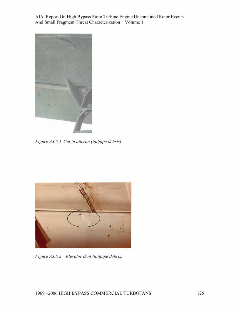
AIA Report On High Bypass Ratio Turbine Engine Uncontained Rotor Events And Small Fragment Threat Characterization Volume 1
1969 –2006 HIGH BYPASS COMMERCIAL TURBOFANS 125
Figure A3.5.1 Cut in aileron (tailpipe debris)
Figure A3.5.2 Elevator dent (tailpipe debris)
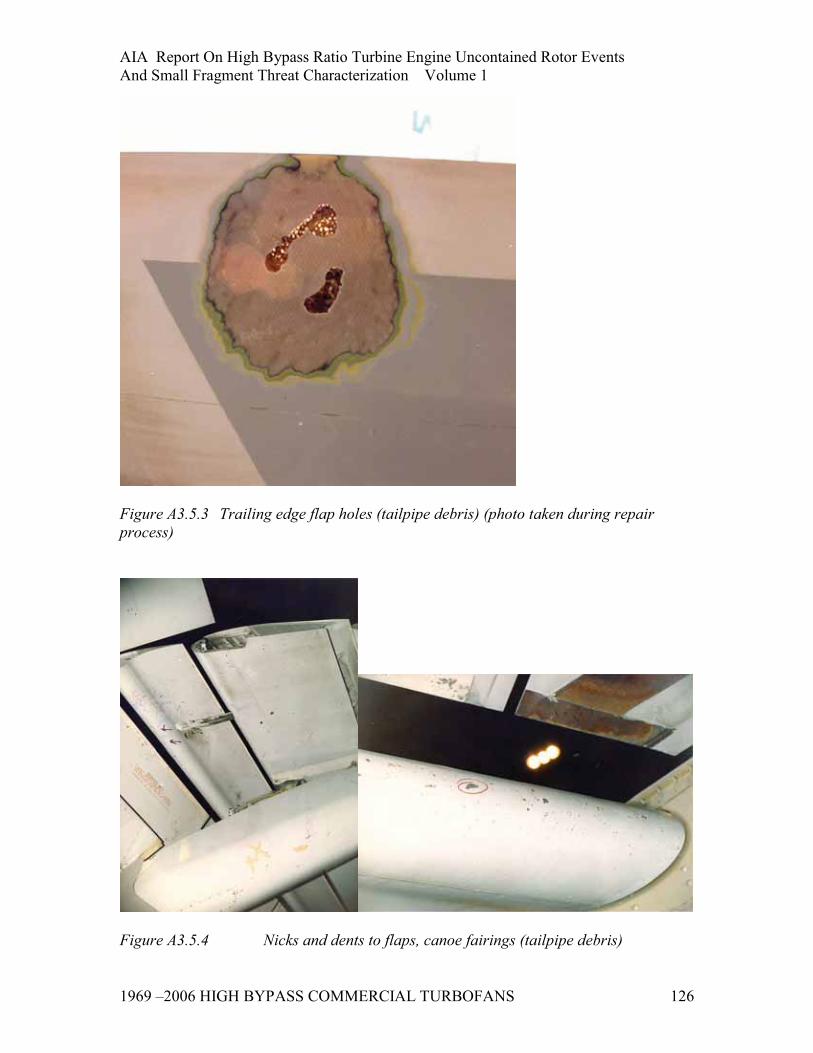
AIA Report On High Bypass Ratio Turbine Engine Uncontained Rotor Events And Small Fragment Threat Characterization Volume 1
1969 –2006 HIGH BYPASS COMMERCIAL TURBOFANS 126
Figure A3.5.3 Trailing edge flap holes (tailpipe debris) (photo taken during repair process)
Figure A3.5.4 Nicks and dents to flaps, canoe fairings (tailpipe debris)
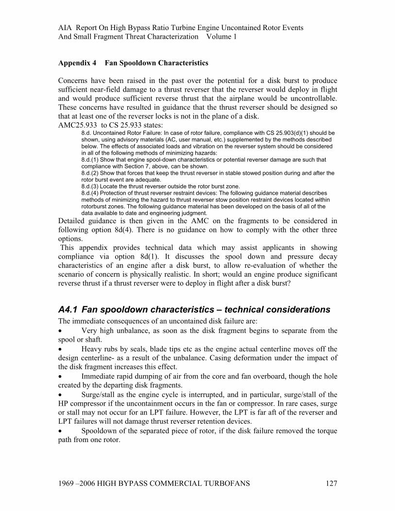
AIA Report On High Bypass Ratio Turbine Engine Uncontained Rotor Events And Small Fragment Threat Characterization Volume 1
1969 –2006 HIGH BYPASS COMMERCIAL TURBOFANS 127
Appendix 4 Fan Spooldown Characteristics
Concerns have been raised in the past over the potential for a disk burst to produce sufficient near-field damage to a thrust reverser that the reverser would deploy in flight and would produce sufficient reverse thrust that the airplane would be uncontrollable. These concerns have resulted in guidance that the thrust reverser should be designed so that at least one of the reverser locks is not in the plane of a disk. AMC25.933 to CS 25.933 states:
8.d. Uncontained Rotor Failure: In case of rotor failure, compliance with CS 25.903(d)(1) should be shown, using advisory materials (AC, user manual, etc.) supplemented by the methods described below. The effects of associated loads and vibration on the reverser system should be considered in all of the following methods of minimizing hazards: 8.d.(1) Show that engine spool-down characteristics or potential reverser damage are such that compliance with Section 7, above, can be shown. 8.d.(2) Show that forces that keep the thrust reverser in stable stowed position during and after the rotor burst event are adequate. 8.d.(3) Locate the thrust reverser outside the rotor burst zone. 8.d.(4) Protection of thrust reverser restraint devices: The following guidance material describes methods of minimizing the hazard to thrust reverser stow position restraint devices located within rotorburst zones. The following guidance material has been developed on the basis of all of the data available to date and engineering judgment.
Detailed guidance is then given in the AMC on the fragments to be considered in following option 8d(4). There is no guidance on how to comply with the other three options. This appendix provides technical data which may assist applicants in showing compliance via option 8d(1). It discusses the spool down and pressure decay characteristics of an engine after a disk burst, to allow re-evaluation of whether the scenario of concern is physically realistic. In short; would an engine produce significant reverse thrust if a thrust reverser were to deploy in flight after a disk burst?
A4.1 Fan spooldown characteristics – technical considerations The immediate consequences of an uncontained disk failure are: �� Very high unbalance, as soon as the disk fragment begins to separate from the spool or shaft. �� Heavy rubs by seals, blade tips etc as the engine actual centerline moves off the design centerline- as a result of the unbalance. Casing deformation under the impact of the disk fragment increases this effect. �� Immediate rapid dumping of air from the core and fan overboard, though the hole created by the departing disk fragments. �� Surge/stall as the engine cycle is interrupted, and in particular, surge/stall of the HP compressor if the uncontainment occurs in the fan or compressor. In rare cases, surge or stall may not occur for an LPT failure. However, the LPT is far aft of the reverser and LPT failures will not damage thrust reverser retention devices. �� Spooldown of the separated piece of rotor, if the disk failure removed the torque path from one rotor.
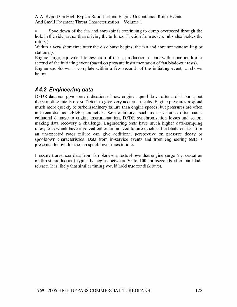
AIA Report On High Bypass Ratio Turbine Engine Uncontained Rotor Events And Small Fragment Threat Characterization Volume 1
1969 –2006 HIGH BYPASS COMMERCIAL TURBOFANS 128
�� Spooldown of the fan and core (air is continuing to dump overboard through the hole in the side, rather than driving the turbines. Friction from severe rubs also brakes the rotors.) Within a very short time after the disk burst begins, the fan and core are windmilling or stationary. Engine surge, equivalent to cessation of thrust production, occurs within one tenth of a second of the initiating event (based on pressure instrumentation of fan blade-out tests). Engine spooldown is complete within a few seconds of the initiating event, as shown below.
A4.2 Engineering data DFDR data can give some indication of how engines spool down after a disk burst; but the sampling rate is not sufficient to give very accurate results. Engine pressures respond much more quickly to turbomachinery failure than engine speeds, but pressures are often not recorded as DFDR parameters. Severe failures such as disk bursts often cause collateral damage to engine instrumentation, DFDR synchronization losses and so on, making data recovery a challenge. Engineering tests have much higher data-sampling rates; tests which have involved either an induced failure (such as fan blade-out tests) or an unexpected rotor failure can give additional perspective on pressure decay or spooldown characteristics. Data from in-service events and from engineering tests is presented below, for the fan spooldown times to idle.
Pressure transducer data from fan blade-out tests shows that engine surge (i.e. cessation of thrust production) typically begins between 30 to 100 milliseconds after fan blade release. It is likely that similar timing would hold true for disk burst.

AIA Report On High Bypass Ratio Turbine Engine Uncontained Rotor Events And Small Fragment Threat Characterization Volume 1
1969 –2006 HIGH BYPASS COMMERCIAL TURBOFANS 129
Event identification
Nature of event
Initial power setting
Time from event initiation to idle speed (fan )
Comments
Manufacturer A
HPT disk burst
Climb 2.5 seconds (DFDR interpolation)
9 seconds after disk burst, DFDR recorded a deployed signal from one reverser sleeve.
Manufacturer A
Mid seal failure on test bed. Contained.
Intermediate (75% N1)
0.6 seconds
Manufacturer A
Fan mid shaft separation. Uncontained LPT blades
Takeoff 2 seconds (DFDR data interpolation)
would expect slower spooldown than for rotor burst.
Manufacturer A
HPC spool burst
Takeoff 2 seconds (DFDR data interpolation)
Manufacturer B
Fan blade-out test A
Red-line N1 2.5 seconds would expect slower spooldown than for rotor burst.
Manufacturer B
Fan blade-out test B
Red-line N1 2.8 seconds would expect slower spooldown than for rotor burst.
Manufacturer B
Fan blade-out test C
Red-line N1 3.3 seconds would expect slower spooldown than for rotor burst.
Manufacturer B
Fan blade-out test D
Red-line N1 1.9 seconds would expect slower spooldown than for rotor burst.
Table A4.1 Spooldown times with high unbalance
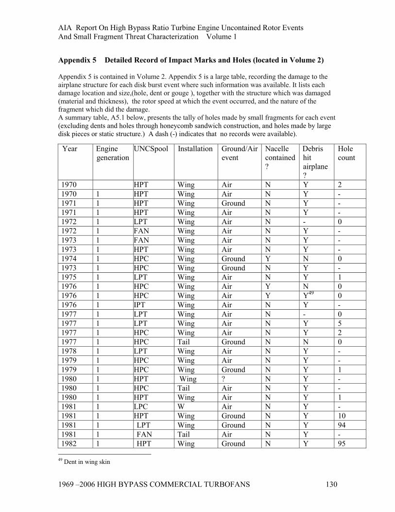
AIA Report On High Bypass Ratio Turbine Engine Uncontained Rotor Events And Small Fragment Threat Characterization Volume 1
1969 –2006 HIGH BYPASS COMMERCIAL TURBOFANS 130
Appendix 5 Detailed Record of Impact Marks and Holes (located in Volume 2)
Appendix 5 is contained in Volume 2. Appendix 5 is a large table, recording the damage to the airplane structure for each disk burst event where such information was available. It lists each damage location and size,(hole, dent or gouge ), together with the structure which was damaged (material and thickness), the rotor speed at which the event occurred, and the nature of the fragment which did the damage. A summary table, A5.1 below, presents the tally of holes made by small fragments for each event (excluding dents and holes through honeycomb sandwich construction, and holes made by large disk pieces or static structure.) A dash (-) indicates that no records were available).
Year Engine generation
UNCSpool Installation Ground/Air event
Nacelle contained?
Debris hit airplane?
Hole count
1970 HPT Wing Air N Y 2 1970 1 HPT Wing Air N Y - 1971 1 HPT Wing Ground N Y - 1971 1 HPT Wing Air N Y - 1972 1 LPT Wing Air N - 0 1972 1 FAN Wing Air N Y - 1973 1 FAN Wing Air N Y - 1973 1 HPT Wing Air N Y - 1974 1 HPC Wing Ground Y N 0 1973 1 HPC Wing Ground N Y - 1975 1 LPT Wing Air N Y 1 1976 1 HPC Wing Air Y N 0 1976 1 HPC Wing Air Y Y49 0 1976 1 IPT Wing Air N Y - 1977 1 LPT Wing Air N - 0 1977 1 LPT Wing Air N Y 5 1977 1 HPC Wing Air N Y 2 1977 1 HPC Tail Ground N N 0 1978 1 LPT Wing Air N Y - 1979 1 HPC Wing Air N Y - 1979 1 HPC Wing Ground N Y 1 1980 1 HPT Wing ? N Y - 1980 1 HPC Tail Air N Y - 1980 1 HPT Wing Air N Y 1 1981 1 LPC W Air N Y - 1981 1 HPT Wing Ground N Y 10 1981 1 LPT Wing Ground N Y 94 1981 1 FAN Tail Air N Y - 1982 1 HPT Wing Ground N Y 95
49 Dent in wing skin
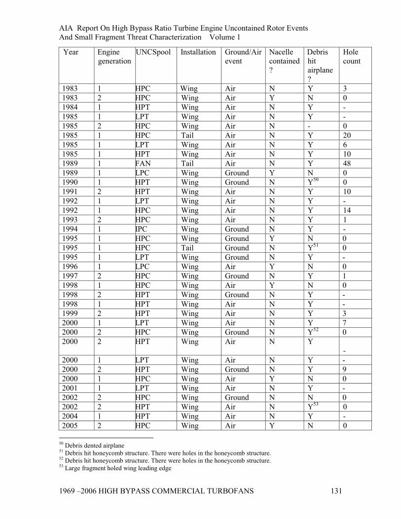
AIA Report On High Bypass Ratio Turbine Engine Uncontained Rotor Events And Small Fragment Threat Characterization Volume 1
1969 –2006 HIGH BYPASS COMMERCIAL TURBOFANS 131
Year Engine generation
UNCSpool Installation Ground/Air event
Nacelle contained?
Debris hit airplane?
Hole count
1983 1 HPC Wing Air N Y 3 1983 2 HPC Wing Air Y N 0 1984 1 HPT Wing Air N Y - 1985 1 LPT Wing Air N Y - 1985 2 HPC Wing Air N - 0 1985 1 HPC Tail Air N Y 20 1985 1 LPT Wing Air N Y 6 1985 1 HPT Wing Air N Y 10 1989 1 FAN Tail Air N Y 48 1989 1 LPC Wing Ground Y N 0 1990 1 HPT Wing Ground N Y50 0 1991 2 HPT Wing Air N Y 10 1992 1 LPT Wing Air N Y - 1992 1 HPC Wing Air N Y 14 1993 2 HPC Wing Air N Y 1 1994 1 IPC Wing Ground N Y - 1995 1 HPC Wing Ground Y N 0 1995 1 HPC Tail Ground N Y51 0 1995 1 LPT Wing Ground N Y - 1996 1 LPC Wing Air Y N 0 1997 2 HPC Wing Ground N Y 1 1998 1 HPC Wing Air Y N 0 1998 2 HPT Wing Ground N Y - 1998 1 HPT Wing Air N Y - 1999 2 HPT Wing Air N Y 3 2000 1 LPT Wing Air N Y 7 2000 2 HPC Wing Ground N Y52 0 2000 2 HPT Wing Air N Y
- 2000 1 LPT Wing Air N Y - 2000 2 HPT Wing Ground N Y 9 2000 1 HPC Wing Air Y N 0 2001 1 LPT Wing Air N Y - 2002 2 HPC Wing Ground N N 0 2002 2 HPT Wing Air N Y53 0 2004 1 HPT Wing Air N Y - 2005 2 HPC Wing Air Y N 0
50 Debris dented airplane 51 Debris hit honeycomb structure. There were holes in the honeycomb structure. 52 Debris hit honeycomb structure. There were holes in the honeycomb structure. 53 Large fragment holed wing leading edge
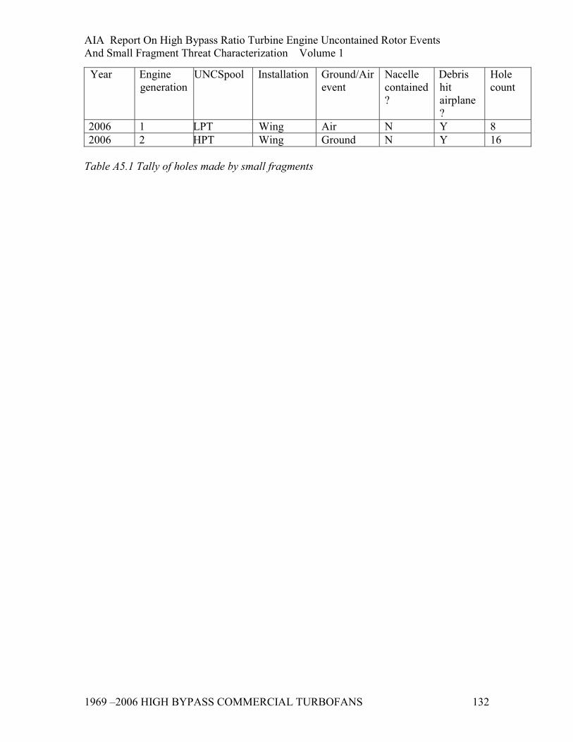
AIA Report On High Bypass Ratio Turbine Engine Uncontained Rotor Events And Small Fragment Threat Characterization Volume 1
1969 –2006 HIGH BYPASS COMMERCIAL TURBOFANS 132
Year Engine generation
UNCSpool Installation Ground/Air event
Nacelle contained?
Debris hit airplane?
Hole count
2006 1 LPT Wing Air N Y 8 2006 2 HPT Wing Ground N Y 16
Table A5.1 Tally of holes made by small fragments
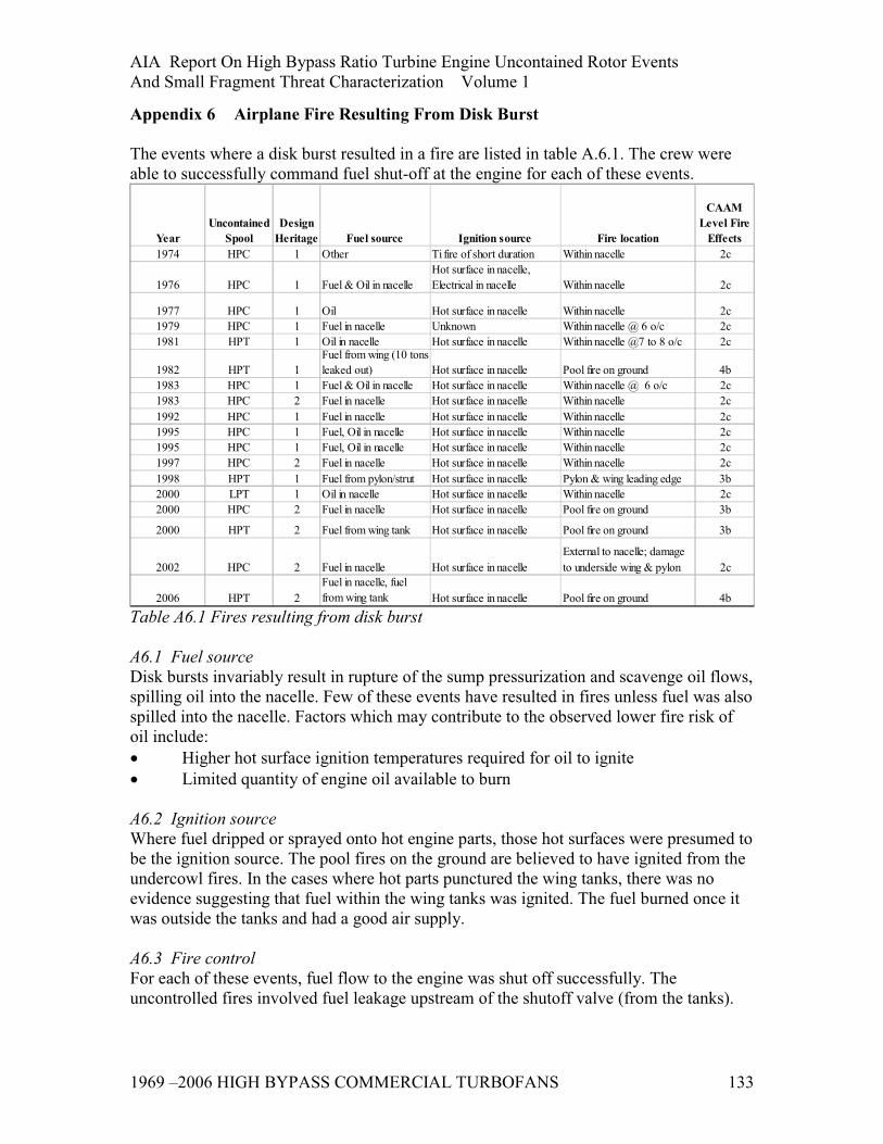
AIA Report On High Bypass Ratio Turbine Engine Uncontained Rotor Events And Small Fragment Threat Characterization Volume 1
1969 –2006 HIGH BYPASS COMMERCIAL TURBOFANS 133
Appendix 6 Airplane Fire Resulting From Disk Burst The events where a disk burst resulted in a fire are listed in table A.6.1. The crew were able to successfully command fuel shut-off at the engine for each of these events.
Table A6.1 Fires resulting from disk burst
A6.1 Fuel source Disk bursts invariably result in rupture of the sump pressurization and scavenge oil flows, spilling oil into the nacelle. Few of these events have resulted in fires unless fuel was also spilled into the nacelle. Factors which may contribute to the observed lower fire risk of oil include: �� Higher hot surface ignition temperatures required for oil to ignite �� Limited quantity of engine oil available to burn
A6.2 Ignition source Where fuel dripped or sprayed onto hot engine parts, those hot surfaces were presumed to be the ignition source. The pool fires on the ground are believed to have ignited from the undercowl fires. In the cases where hot parts punctured the wing tanks, there was no evidence suggesting that fuel within the wing tanks was ignited. The fuel burned once it was outside the tanks and had a good air supply.
A6.3 Fire control For each of these events, fuel flow to the engine was shut off successfully. The uncontrolled fires involved fuel leakage upstream of the shutoff valve (from the tanks).
YearUncontained
SpoolDesign
Heritage Fuel source Ignition source Fire location
CAAM Level Fire
Effects1974 HPC 1 Other Ti fire of short duration Within nacelle 2c
1976 HPC 1 Fuel & Oil in nacelleHot surface in nacelle, Electrical in nacelle Within nacelle 2c
1977 HPC 1 Oil Hot surface in nacelle Within nacelle 2c1979 HPC 1 Fuel in nacelle Unknown Within nacelle @ 6 o/c 2c1981 HPT 1 Oil in nacelle Hot surface in nacelle Within nacelle @7 to 8 o/c 2c
1982 HPT 1Fuel from wing (10 tons leaked out) Hot surface in nacelle Pool fire on ground 4b
1983 HPC 1 Fuel & Oil in nacelle Hot surface in nacelle Within nacelle @ 6 o/c 2c1983 HPC 2 Fuel in nacelle Hot surface in nacelle Within nacelle 2c1992 HPC 1 Fuel in nacelle Hot surface in nacelle Within nacelle 2c1995 HPC 1 Fuel, Oil in nacelle Hot surface in nacelle Within nacelle 2c1995 HPC 1 Fuel, Oil in nacelle Hot surface in nacelle Within nacelle 2c1997 HPC 2 Fuel in nacelle Hot surface in nacelle Within nacelle 2c1998 HPT 1 Fuel from pylon/strut Hot surface in nacelle Pylon & wing leading edge 3b2000 LPT 1 Oil in nacelle Hot surface in nacelle Within nacelle 2c2000 HPC 2 Fuel in nacelle Hot surface in nacelle Pool fire on ground 3b
2000 HPT 2 Fuel from wing tank Hot surface in nacelle Pool fire on ground 3b
2002 HPC 2 Fuel in nacelle Hot surface in nacelleExternal to nacelle; damage to underside wing & pylon 2c
2006 HPT 2Fuel in nacelle, fuel from wing tank Hot surface in nacelle Pool fire on ground 4b
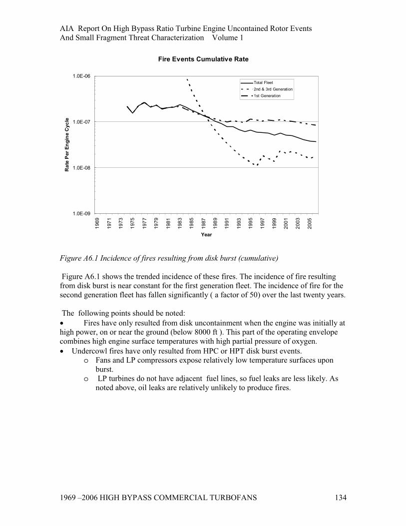
AIA Report On High Bypass Ratio Turbine Engine Uncontained Rotor Events And Small Fragment Threat Characterization Volume 1
1969 –2006 HIGH BYPASS COMMERCIAL TURBOFANS 134
Figure A6.1 Incidence of fires resulting from disk burst (cumulative)
Figure A6.1 shows the trended incidence of these fires. The incidence of fire resulting from disk burst is near constant for the first generation fleet. The incidence of fire for the second generation fleet has fallen significantly ( a factor of 50) over the last twenty years.
The following points should be noted: �� Fires have only resulted from disk uncontainment when the engine was initially at high power, on or near the ground (below 8000 ft ). This part of the operating envelope combines high engine surface temperatures with high partial pressure of oxygen. �� Undercowl fires have only resulted from HPC or HPT disk burst events.
o Fans and LP compressors expose relatively low temperature surfaces upon burst.
o LP turbines do not have adjacent fuel lines, so fuel leaks are less likely. As noted above, oil leaks are relatively unlikely to produce fires.
Fire Events Cumulative Rate
1.0E-09
1.0E-08
1.0E-07
1.0E-06
1969
1971
1973
1975
1977
1979
1981
1983
1985
1987
1989
1991
1993
1995
1997
1999
2001
2003
2005
Year
Rat
e P
er E
ngin
e C
ycle
Total Fleet2nd & 3rd Generation1st Generation

AIA Report On High Bypass Ratio Turbine Engine Uncontained Rotor Events And Small Fragment Threat Characterization Volume 1
1969 –2006 HIGH BYPASS COMMERCIAL TURBOFANS 135
Appendix 7 Large Fragment Velocity
In some cases, though not all54, debris maps of airports have been made showing where pieces of engine were found after an event. These can be used as part of a search for missing disks or disk pieces. These maps can also be used to derive an estimate of the speed at which the disk piece travelled when it initially left the nacelle, if the disk velocity vector can be identified and resolved into a forward (airplane speed) component and a lateral (disk in-plane velocity) component. This vector is necessarily an average value of the velocity in the horizontal plane. By testing a range of trajectories compatible with the landing site of the piece, a range of possible tangential velocities can be estimated. Estimates of disk fragment tangential velocity can also be derived from the distribution of debris dropped from the airplane after takeoff. Values derived from high altitude events may influenced by drag effects and be less informative about the initial disk speed than values derived from on-ground events. There is uncertainty in the above calculations associated with incomplete fragment recovery, questions regarding wind speed, precise location of the airplane at the time of burst and incomplete documentation of fragment resting place. Nevertheless, the estimates are a useful indicator.
In other cases, although debris maps were not plotted, information was recorded about the location where a disk piece was found – that it was found in the engine nacelle or on the runway where the event took place – which gives a clear qualitative indication of the disk fragment velocity.
This type of information was available for 19 disk burst events. No conclusions could be reached for two of these, but estimates of fragment speed were successfully made for the remaining 17. The summary of this data was presented in Figure 9 and is repeated here for convenient reference.
54 Many events are immediately followed by efforts to clear the runway of debris as quickly as possible, to allow normal operations to resume. The debris on the runway is often swept into a heap and locations of individual small pieces are not recorded.
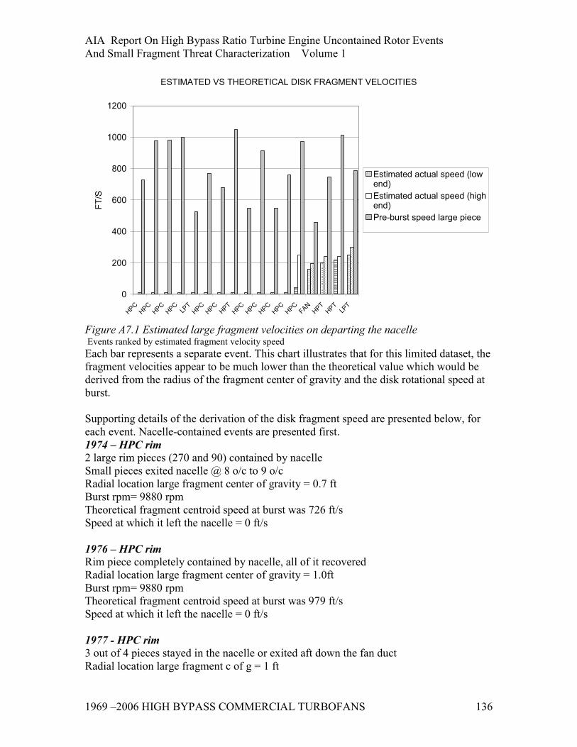
AIA Report On High Bypass Ratio Turbine Engine Uncontained Rotor Events And Small Fragment Threat Characterization Volume 1
1969 –2006 HIGH BYPASS COMMERCIAL TURBOFANS 136
Figure A7.1 Estimated large fragment velocities on departing the nacelle Events ranked by estimated fragment velocity speedEach bar represents a separate event. This chart illustrates that for this limited dataset, the fragment velocities appear to be much lower than the theoretical value which would be derived from the radius of the fragment center of gravity and the disk rotational speed at burst.
Supporting details of the derivation of the disk fragment speed are presented below, for each event. Nacelle-contained events are presented first. 1974 – HPC rim 2 large rim pieces (270 and 90) contained by nacelle Small pieces exited nacelle @ 8 o/c to 9 o/c Radial location large fragment center of gravity = 0.7 ft Burst rpm= 9880 rpm Theoretical fragment centroid speed at burst was 726 ft/s Speed at which it left the nacelle = 0 ft/s
1976 – HPC rim Rim piece completely contained by nacelle, all of it recovered Radial location large fragment center of gravity = 1.0ft Burst rpm= 9880 rpm Theoretical fragment centroid speed at burst was 979 ft/s Speed at which it left the nacelle = 0 ft/s
1977 - HPC rim 3 out of 4 pieces stayed in the nacelle or exited aft down the fan duct Radial location large fragment c of g = 1 ft
ESTIMATED VS THEORETICAL DISK FRAGMENT VELOCITIES
0
200
400
600
800
1000
1200
HPCHPC
HPCHPC
LPT
HPCHPC
HPTHPC
HPCHPC
HPCHPC
FANHPT
HPTLP
T
FT/S
Estimated actual speed (lowend)Estimated actual speed (highend)Pre-burst speed large piece
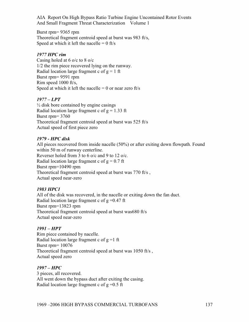
AIA Report On High Bypass Ratio Turbine Engine Uncontained Rotor Events And Small Fragment Threat Characterization Volume 1
1969 –2006 HIGH BYPASS COMMERCIAL TURBOFANS 137
Burst rpm= 9365 rpm Theoretical fragment centroid speed at burst was 983 ft/s, Speed at which it left the nacelle = 0 ft/s
1977 HPC rim Casing holed at 6 o/c to 8 o/c 1/2 the rim piece recovered lying on the runway. Radial location large fragment c of g = 1 ft Burst rpm= 9591 rpm Rim speed 1000 ft/s, Speed at which it left the nacelle = 0 or near zero ft/s
1977 – LPT ½ disk bore contained by engine casings Radial location large fragment c of g = 1.33 ft Burst rpm= 3760 Theoretical fragment centroid speed at burst was 525 ft/s Actual speed of first piece zero
1979 - HPC disk All pieces recovered from inside nacelle (50%) or after exiting down flowpath. Found within 50 m of runway centerline. Reverser holed from 3 to 6 o/c and 9 to 12 o/c. Radial location large fragment c of g = 0.7 ft Burst rpm=10490 rpm Theoretical fragment centroid speed at burst was 770 ft/s , Actual speed near-zero
1983 HPC1 All of the disk was recovered, in the nacelle or exiting down the fan duct. Radial location large fragment c of g =0.47 ft Burst rpm=13823 rpm Theoretical fragment centroid speed at burst was680 ft/s Actual speed near-zero
1991 – HPT Rim piece contained by nacelle. Radial location large fragment c of g =1 ft Burst rpm= 10076 Theoretical fragment centroid speed at burst was 1050 ft/s , Actual speed zero
1997 – HPC 3 pieces, all recovered.
All went down the bypass duct after exiting the casing. Radial location large fragment c of g =0.5 ft
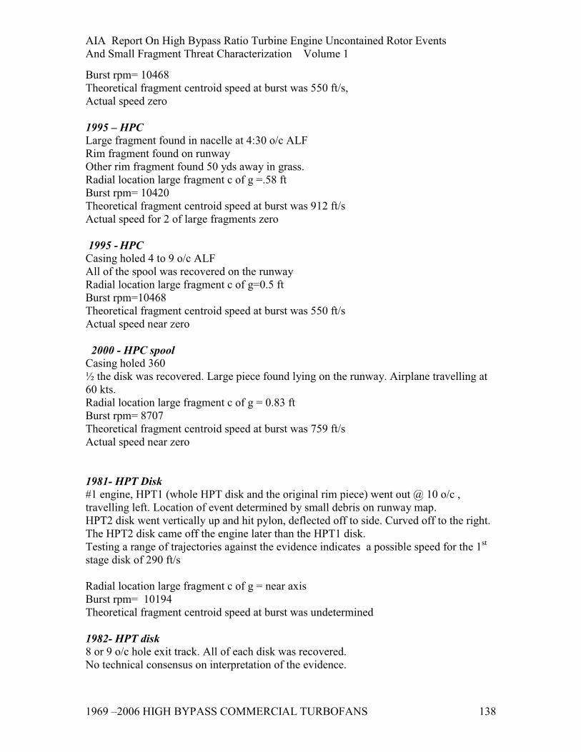
AIA Report On High Bypass Ratio Turbine Engine Uncontained Rotor Events And Small Fragment Threat Characterization Volume 1
1969 –2006 HIGH BYPASS COMMERCIAL TURBOFANS 138
Burst rpm= 10468 Theoretical fragment centroid speed at burst was 550 ft/s, Actual speed zero
1995 – HPC Large fragment found in nacelle at 4:30 o/c ALF Rim fragment found on runway Other rim fragment found 50 yds away in grass. Radial location large fragment c of g =.58 ft Burst rpm= 10420 Theoretical fragment centroid speed at burst was 912 ft/s Actual speed for 2 of large fragments zero
1995 - HPC Casing holed 4 to 9 o/c ALF All of the spool was recovered on the runway Radial location large fragment c of g=0.5 ft Burst rpm=10468 Theoretical fragment centroid speed at burst was 550 ft/s Actual speed near zero
2000 - HPC spoolCasing holed 360 ½ the disk was recovered. Large piece found lying on the runway. Airplane travelling at 60 kts. Radial location large fragment c of g = 0.83 ft Burst rpm= 8707 Theoretical fragment centroid speed at burst was 759 ft/s Actual speed near zero
1981- HPT Disk #1 engine, HPT1 (whole HPT disk and the original rim piece) went out @ 10 o/c , travelling left. Location of event determined by small debris on runway map. HPT2 disk went vertically up and hit pylon, deflected off to side. Curved off to the right. The HPT2 disk came off the engine later than the HPT1 disk. Testing a range of trajectories against the evidence indicates a possible speed for the 1st
stage disk of 290 ft/s
Radial location large fragment c of g = near axis Burst rpm= 10194 Theoretical fragment centroid speed at burst was undetermined
1982- HPT disk 8 or 9 o/c hole exit track. All of each disk was recovered. No technical consensus on interpretation of the evidence.

AIA Report On High Bypass Ratio Turbine Engine Uncontained Rotor Events And Small Fragment Threat Characterization Volume 1
1969 –2006 HIGH BYPASS COMMERCIAL TURBOFANS 139
Radial location large fragment c of g = undetermined (whole disk) Burst rpm= 10526 Theoretical fragment centroid speed at burst was undetermined
1985 - HPC9 disk Casing holed at 5o/c for bore piece 6, and 6 o/c, 7,8,10 and 12 o/c for rim pieces About ½ the disk recovered in all. This, with the distribution of release angles, suggests we collected pieces with a representative range of tangential vector directions. Event at 3500 ft, per DFDR. Disk pieces scattered over a line to left and right of airplane. Neglecting drag, it would take pieces 15 seconds to fall from 3500 ft. Testing a range of trajectories against the locations where large pieces were found on the ground indicates a possible tangential speed range of 40 ft/s to 250 ft/s (depending on the initial vertical component) Radial location large fragment c of g = 0.9 ft Burst rpm= 10272 Theoretical fragment centroid speed at burst was 971 ft/s
1989 Fan disk 1:45 o/c disk piece hit elevator leading edge, other piece went at 7:30 o/c Effectively all of the disk was recovered. Extensive search efforts for the disk included trajectory/drag modeling. When the disk was eventually found, the model could be forced to the correct location by using more equal disk exit velocities than had been previously assumed (assumed 107 and 544 ft/s). The corrected velocities were 158 ft/s and 197 ft/s at exit from the nacelle. Radial location large fragment c of g = 1.3 ft Burst rpm= 3363 Theoretical fragment centroid speed at burst was 459 ft/s
1999 HPT air seal 12 o/c hole in cowl, #1 engine Climb, 1000 ft AGL, fwd speed 160 kts (270 ft/s 2/3 of seal found on right of airplane track, same distance off track as L/H reverser latch beam and reverser latch but 600 yds further along the track. Testing a range of possible trajectories indicates a possible speed range – for the 2/3 fragment – of 200 to 240 ft/s. The 1/3 segment was not recovered and so no velocity calculation is possible. Radial location large fragment c of g = 0.5 ft Burst rpm= 14200 Theoretical fragment centroid speed at burst was 746 ft/s
1990 HPT disk rim 7 o/c hole in casing Air plane speed was 150 knots. Rim piece recovered (all). The rim piece travelled 1700 ft, at a vector 40� from the plane of the rotor. Corresponds to 300 ft/s for rim piece.
AIA Report On High Bypass Ratio Turbine Engine Uncontained Rotor Events And Small Fragment Threat Characterization Volume 1
1969 –2006 HIGH BYPASS COMMERCIAL TURBOFANS 140
Testing a range of trajectories against the locations where the rim piece was found on the ground indicates a possible tangential speed range of 220 ft/s to 240 ft/s (depending on the initial vertical component). Radial location large fragment c of g = 1 ft Burst rpm= 9639 Theoretical fragment centroid speed at burst was 1012 ft/s
2000- LPT disks Casing hole 3 o/c and 9 o/c Debris collected from ground under airplane track. Retrieved 33 post piece for LPT 1 and 46 post piece for LPT4. Airplane at 300 ft for event, 600 ft over location 5,6,7, CAS 180 kts. Testing a range of possible trajectories indicates a possible tangential speed range of 250 to 300 ft/s Radial location large fragment c of g = 1.55 ft Burst rpm= 5640 Theoretical fragment centroid speed at burst was 788 ft/s
AIA Report On High Bypass Ratio Turbine Engine Uncontained Rotor Events And Small Fragment Threat Characterization Volume 1
1969 –2006 HIGH BYPASS COMMERCIAL TURBOFANS 141
Appendix 8 Masses Of Collected Small Fragments
Appendix 8 is provided in volume 2 It contains a photograph and/or short verbal description of each small fragment recovered from inside the airplane and a description of where it was found.
AIA Report On High Bypass Ratio Turbine Engine Uncontained Rotor Events And Small Fragment Threat Characterization Volume 1
1969 –2006 HIGH BYPASS COMMERCIAL TURBOFANS 142
Appendix 9 CAAM Classifications
A summary of the event severity classifications developed by the CAAM committee, for those effects most closely related to disk uncontainment, is presented below. A full list is available in Reference 8.
LEVEL 0 – CONSEQUENCES WITH NO SAFETY EFFECT. b. Casing uncontained engine failure, contained within the nacelle.
LEVEL 1 - MINOR CONSEQUENCES. a. Uncontained nacelle damage confined to affected nacelle/APU area. LEVEL 2 - SIGNIFICANT CONSEQUENCES. a. Nicks, dents and small penetrations in any aircraft principal structural element
55.
b. Slow depressurization. c. Controlled fires (i.e., inside fire zones56). Tailpipe fires that do not impinge upon aircraft structure, or present an ignition source to co-located flammable material, are considered level 2 also. d. (1) Flammable fluid leaks that present a fire concern57. Specifically fuel leaks in the presence of an ignition source and of sufficient magnitude to produce a large fire. d. (2) Fuel leaks that present a range concern for the airplane. e. Minor injuries. f. Multiple propulsion system or APU malfunctions, or related events, where one engine remains shutdown but continued safe flight at an altitude 1,000 feet above terrain along the intended route is possible. This carries with it an assumption that the aircraft is at least under partial power for any length of time longer than transient events (see note associated with level 3.e.) h. Separation of propulsion system, inlet, reverser blocker door, translating sleeve or similar substantial pieces of aerodynamic surface without level 3. Separations on the 55 The previous definition related to “aircraft primary structure”. There was considerable debate over what was considered primary structure. 58 The previous definition stated that controlled fires were those which were extinguished by normal on-board fire extinguishing equipment. This led to the classification of a number of events as uncontrolled fires, which did not appear to the committee to meet the intent of the definition. For instance, fires which could easily have been extinguished by the onboard system had the pilot chosen to use it, small fires which were immediately extinguished by ground crew so that the pilot had no opportunity to use the onboard system, and fires which due to their location were not extinguishable by the onboard system but nevertheless presented no threat to the aircraft (such as grass fires) – all of these were categorized as “uncontrolled” according to the previous definition. The CAAM committee concluded that a better definition of the term “controlled” was whether the fire had impinged upon, or could have impinged upon, the remainder of the airplane
57 It is recognized that the words “present a concern” initially appear inconsistent with the philosophy of deciding hazard levels according to what actually happened. The qualifiers for 2.d. were found to be necessary to eliminate those fuel leaks that were so small that, although outside maintenance manual limits, they had no airplane-level effect. Further consideration confirms that the severity level for 2.d. is based on the actual fuel leak, not on the potential consequence of uncontrolled fire or fuel exhaustion

AIA Report On High Bypass Ratio Turbine Engine Uncontained Rotor Events And Small Fragment Threat Characterization Volume 1
1969 –2006 HIGH BYPASS COMMERCIAL TURBOFANS 143
ground in the process of cycling the reverser are excluded (i.e., low speed, post-thrust reversal.) i. Partial in-flight reverser deployment or propeller pitch change malfunction without level 3 consequences.
LEVEL 3 - SERIOUS CONSEQUENCES. a. Substantial damage to the aircraft or second unrelated system. (1) "Substantial damage
58" in this context means damage or structural failure that
adversely affects the limit loads capability of a primary structural element, the performance or flight characteristics of the aircraft, and that would normally require major repair or replacement of the affected components. (Typically not considered “substantial damage” are engine failure damage limited to the engine or mount system, bent fairings or cowlings, dented skin, small puncture holes in the skin or fabric, or damage to landing gear associated with runway departures, wheel, tires, flaps, engine accessories on the failed engine, brakes or wing tips). (2) Damage to a second unrelated system must impact the ability to continue safe flight and landing. Coordination and agreement between the engine/propeller/APU manufacturer and the airframe manufacturer may be required to properly categorize events related to second system damage. (3) Small penetrations of aircraft fuel lines or aircraft fuel tanks, where the combined penetration areas exceed two square inches
59. Assistance of the airframe manufacturer
should be sought when questions arise. (4) Damage to a second engine (cross-engine debris) which results in a significant loss of thrust or an operational problem requiring pilot action to reduce power. Minor damage which was not observed by the crew during flight and which did not affect the ability of the engine to continue safe operation for the rest of the flight is excluded, being considered a level 2 event. b. Uncontrolled fires – which escape the fire zone and impinge flames onto the wing or fuselage, or act as ignition sources for flammable material anticipated to be present outside the fire zone. c. Rapid depressurization of the cabin. d. Permanent loss of thrust or power greater than one propulsion system. LEVEL 4 - SEVERE CONSEQUENCES. a. Forced landing. Forced landing is defined as the inability to continue flight where imminent landing is obvious but aircraft controllability is not necessarily lost (e.g., total power loss due to fuel exhaustion will result in a "forced landing”). An air turn back or diversion due to a malfunction is not a forced landing, since there is a lack of urgency and
58 A level 2 event may result in an emergency being declared to initiate ATC priority sequencing. This does not inherently imply that the event was a level 3. 6 This definition departs somewhat from the NTSB definition. Clarification was found advisable by the team after some difficulties in using the NTSB definition. 59 The concern is exhaustion of fuel reserves.
AIA Report On High Bypass Ratio Turbine Engine Uncontained Rotor Events And Small Fragment Threat Characterization Volume 1
1969 –2006 HIGH BYPASS COMMERCIAL TURBOFANS 144
the crew has the ability to select where they will perform the landing. 60
However, off-airport landings are almost always forced landings. b. Actual loss of aircraft (as opposed to economic) while occupants were on board
61.
c. Serious injuries or fatalities.62
LEVEL 5 - CATASTROPHIC CONSEQUENCES. Catastrophic outcome
63. An occurrence resulting in multiple fatalities, usually with the
loss of the airplane.
GENERAL NOTES APPLICABLE TO ALL EVENT HAZARD LEVELS. a. The severity of aircraft damage is based on the consequences and damage that actually occurred. b. Injuries resulting from an emergency evacuation rather than from the event that caused the evacuation are not considered in evaluating the severity of the event. It is recognized that emergency evacuations by means of the slides can result in injuries, without regard to the kind of event precipitating the evacuation. c. It is recognized that there is some overlap between the definitions of hazard levels and the characterization of events, particularly for the lower hazard levels (for example, uncontrolled fire). Efforts were made to develop more objective hazard level definitions, rather than defining by example; these efforts were not successful.
60 Where it is unclear whether the landing was forced, it may be helpful to consider whether the pilot had any alternative to landing at the closest airport .61 Hull losses where the airplane could have been repaired, but repair would not have been cost effective, are excluded. Additionally, hull losses that occurred well after the event because appropriate action was not taken to further mitigate damage (i.e., fire breaking out because no fire equipment was available) are not considered hull losses for the purposes of this threat evaluation. Some degree of judgment may be required in determining whether the hull loss qualifies for inclusion 62 In this context, serious injuries are intended as injuries of a life-threatening nature. This is different from the NTSB definition, which would include most simple fractures. 63 Extension of the use of the CAAM database to the entire propulsion system was associated with a desire to discriminate between the kind of events that resulted in a small number of serious injuries or fatalities, and those that resulted in serious injuries or fatalities to most or all of the airplane occupants. This was felt to be a useful discriminator by Transport Airplane Directorate. CAAM Level 4, as defined in the original report, was therefore split into two levels, level 4 and level 5.