AI Tutorial
22
ENT 5051, Scientific Illustration of Insects Fall Semester, 2006 last updated 9 November 2006 1 ADOBE ILLUSTRATOR CS OR CS2: A TUTORIAL FOR ENTOMOLOGISTS PRELIMINARIES Preparing a drawing for import into Illustrator The first step is to scan a pencil sketch using Adobe Photoshop (or another application that can capture an image from a flatbed scanner). A digital photograph can also be used. This scanned image or photograph will be “placed” into Adobe Illustrator as a “template layer” that will serve as the basis of the Illustrator drawing. Open Adobe Photoshop File Import {scanner} TWAIN… Use these scanner settings (may have slightly different names depending on the scanner; I am currently using an Epson Perfection 2400 Photo scanner): Flat bed Black & white photo 150 or 300 dpi (max) scale 100% Place image face down on scanner. Scan Save as a Photoshop document (.psd), grayscale (Gray/8) or as a high quality JPEG. If the original sketch has several views on the same page (e.g., dorsal, ventral, and lateral views of a specimen), copy and paste each view into separate Photoshop documents. Use the “rectangular marquee” or “lasso tool” to select the view to copy. File > Copy File > New. . . (name it) File > Paste Save (save all the different Photoshop documents into a single folder). See the separate handout on how to edit scanned images and photographs using Photoshop.
-
Upload
funkyblues -
Category
Documents
-
view
226 -
download
0
Transcript of AI Tutorial
8/8/2019 AI Tutorial
http://slidepdf.com/reader/full/ai-tutorial 1/22
ENT 5051, Scientific Illustration of Insects Fall Semester, 2006
last updated 9 November 20061
ADOBE ILLUSTRATOR CS OR CS2:A TUTORIAL FOR ENTOMOLOGISTS
PRELIMINARIES
Preparing a drawing for import into Illustrator
The first step is to scan a pencil sketch using Adobe Photoshop (or another application that cancapture an image from a flatbed scanner). A digital photograph can also be used. This scanned
image or photograph will be “placed” into Adobe Illustrator as a “template layer” that will serve
as the basis of the Illustrator drawing.
Open Adobe Photoshop
FileImport
{scanner} TWAIN…
Use these scanner settings (may have slightly different names depending on the scanner; I am
currently using an Epson Perfection 2400 Photo scanner):Flat bed
Black & white photo
150 or 300 dpi (max)
scale 100%
Place image face down on scanner.
Scan
Save as a Photoshop document (.psd), grayscale (Gray/8) or as a high quality JPEG.
If the original sketch has several views on the same page (e.g., dorsal, ventral, and lateral viewsof a specimen), copy and paste each view into separate Photoshop documents. Use the
“rectangular marquee” or “lasso tool” to select the view to copy.
File > Copy
File > New. . . (name it)
File > PasteSave (save all the different Photoshop documents into a single folder).
See the separate handout on how to edit scanned images and photographs using Photoshop.
8/8/2019 AI Tutorial
http://slidepdf.com/reader/full/ai-tutorial 2/22
ENT 5051, Scientific Illustration of Insects Fall Semester, 2006
last updated 9 November 20062
ADOBE ILLUSTRATOR
PREPARING FOR ILLUSTRATION
Open Illustrator
Creating a new file:
FILE
New...
Name: name the document.
Artboard Size: is determined by the plate size of the journal or other medium you will be
publishing in. For example, for a thesis, choose Letter. Notice that you can select
the units of the page dimensions (cm, inches, points, etc.)Color Mode: for black and white line drawing doesn’t matter, but for color work that
will be printed in a journal select CMYK, for web use or for printing on a desktopcolor printer use RGB.
Saving the file as a page template for repeated use and setting margins:
Usually you will have more than one page of illustrations in your thesis or publication. Also,
you will have to place your illustrations within the margin limits set by the publisher. Forexample, thesis requirements usually ask for a 1.5 inch left margin and 1 inch top, bottom, and
right margins. You can create a set of guides and save them in a template file for repeated use.
VIEW
Show page tiling (Printers can’t print to the very edge of a page; page tiling shows the partsof the page that can accept ink by the printer. This isn’t very important, but I find it
informative.)
On the Tools palette (if the Tools palette is not visible, select it under Window) select the
Rectangle tool then double click anywhere on the artboard. A dialog box will appear allowing
you to set the size of the rectangle. To accommodate thesis margins create a box 6 X 9 in.Leave the rectangle “selected.” If it becomes deselected, click on it with the Selection tool
(black arrow).
WINDOW
Align palette (under options - open the little sideways triangle button on the upper right -make sure Align to artboard is selected)
Center the rectangle horizontally and vertically using the align tools
Then under Window, select Transform and on the rectangle symbol on the left, select the center
left square, then for the X coordinate type in 1.5 in and hit the Return key. In fact, you can
position and size any shape all within the Transform palette if you prefer.
8/8/2019 AI Tutorial
http://slidepdf.com/reader/full/ai-tutorial 3/22
ENT 5051, Scientific Illustration of Insects Fall Semester, 2006
last updated 9 November 20063
With the rectangle at the correct size and position, keep it selected (or reselect it) and under
VIEW select Guides. . ., Make guides.
Finally, go to FILE, Save as Template. . . and name the template. Notice that it has the
extension .ait (Adobe Illustrator template). Now, whenever you need to create a new plate of
illustrations, you can select New from template. . . and use this file for additional plates. Youcan create different templates for different journals and save them in Illustrator’s Template
folder.
NOTE: Older versions of Illustrator (ver. 10 and earlier) did not have the Save as Templatefunction.
Placing the scanned pencil sketch into Illustrator:
Open a New file or a New from Template file.
Under FILEPlace. . .
Navigate to the folder containing the files of your scanned Photoshop documents.
Make sure LINK and TEMPLATE are both checked and then select Place.
Go to the Layers palette (under Window menu, Layers). You will see that a Template
Layer was created as well as a Layer 1.Continue to place one by one all of your scanned Photoshop documents onto the artboard
that will serve as the first plate of illustrations in your publication. Each placed pencil
sketch will appear as a Template [template layers have the “triangle, box, circle” iconnext to them rather than the “eye” icon].
In Layers palette “unlock” each template. In the Toolbox palette, select the Selectionarrow (black arrow). By clicking on the image of the pencil sketch or the template“target” button in the layers palette, a red “bounding box” appears (it should have open
adjustment squares at the corners and at the midlengths of the 4 sides; if a bounding box
does not appear, select “Show Bounding Box” from the View menu. If you placed more
than one document on your artboard, they will stack one on top of each other. You candrag the images around to uncover them and see them all by selecting or targeting each
one.
Very likely, your images will be imported in Illustrator larger or smaller than you need to fitthem all on the page. You will need to scale them up or down. When you have a template
selected, go to the Toolbox and double click on the Scale tool or go to Object, Transform,Scale. You get a pop-up window with scale properties. Select Uniform and the appropriate
scale, e.g., 75%, 50%, etc. Also select Preview, then OK. Scale the individual templates asappropriate to the size of the artboard. Don’t crowd them, but on the other hand, don’t leave too
much white space between individual views. If you want all your drawings throughout your
publication to be scaled at the same size, be sure to record the percent reduction or enlargement
used.
8/8/2019 AI Tutorial
http://slidepdf.com/reader/full/ai-tutorial 4/22
ENT 5051, Scientific Illustration of Insects Fall Semester, 2006
last updated 9 November 20064
With the Selection arrow (black arrow) select other templates and scale those. You can select all
templates by holding down the shift key while selecting additional template then scale all atonce.
In the Layers palette, if you double click on a template, a Layer Options pop-up window
appears. You can rename the template and also dim or enhance intensity of template image. Iusually leave this alone (the default is dim to 50%), but in the Transparency palette (under
Window), I adjust the opacity of the template background when a part of one template overlaps
and obscures a part of another.. I usually set “opacity” to 50%-75% so I can see behind
overlapping images.
You can move selected templates (or any object or path) on the art board by dragging into
position with the selection arrow or you can move with the arrow keys on the computer’s
keyboard after the item is selected. Set the selectivity of the increment of movement as follows:
Edit
Preferences
General...Keyboard Increment: [I have it set to 0.005 cm; this is your choice, but a smallincrement is recommended for fine adjustments of position.]
Regardless of the increment you set, if you hold down the shift key while moving with
the arrow keys, the object moves by a factor of 10.
With a template selected, you can also scale by dragging with selection arrow on a corner or
side. But first, under View, select Show Bounding Box if the bounding box is not active(otherwise a red border solid corner squares shows around the template). The solid squares
become open and you can drag them to change the size of the template. However, this scaling
will not be proportional. To get proportional scaling, hold down the shift key while dragging.If you scale this way, make sure separate illustrations of the same specimen are scaled the sameamount.
To rotate a template, hold selection arrow just to the outside of a corner of the bounding box and
drag to rotate to desired position.
Once the templates are scaled, positioned, rotated, etc. lock them as needed. They cannot be
modified or moved when they are locked.
Setting preferences:
In addition to setting the keyboard increment settings, there are a number of other settings to be
aware of in Preferences, including the following IMPORTANT PREFERENCES SETTING:If you intend to copy and paste Illustrator “paths” into Photoshop for further rendering (i.e., to
produce a full habitus color illustration in Photoshop), you must do the following in Adobe
Illustrator [In fact, go ahead and set up the preferences as described below whether or not you
intend to import paths into Photoshop, it will not affect your Illustrator drawing]:
8/8/2019 AI Tutorial
http://slidepdf.com/reader/full/ai-tutorial 5/22
ENT 5051, Scientific Illustration of Insects Fall Semester, 2006
last updated 9 November 20065
Illustrator
Preferences
File handling and Clipboard…
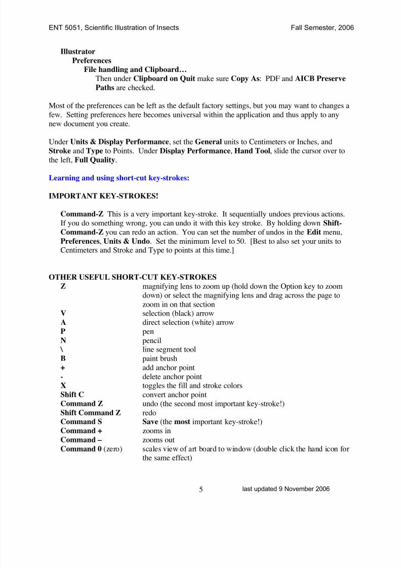
Then under Clipboard on Quit make sure Copy As: PDF and AICB Preserve
Paths are checked.
Most of the preferences can be left as the default factory settings, but you may want to changes a
few. Setting preferences here becomes universal within the application and thus apply to any
new document you create.
Under Units & Display Performance, set the General units to Centimeters or Inches, and
Stroke and Type to Points. Under Display Performance, Hand Tool, slide the cursor over to
the left, Full Quality.
Learning and using short-cut key-strokes:
IMPORTANT KEY-STROKES!
Command-Z This is a very important key-stroke. It sequentially undoes previous actions.
If you do something wrong, you can undo it with this key stroke. By holding down Shift-
Command-Z you can redo an action. You can set the number of undos in the Edit menu,
Preferences, Units & Undo. Set the minimum level to 50. [Best to also set your units toCentimeters and Stroke and Type to points at this time.]
OTHER USEFUL SHORT-CUT KEY-STROKES
Z magnifying lens to zoom up (hold down the Option key to zoom
down) or select the magnifying lens and drag across the page tozoom in on that sectionV selection (black) arrow
A direct selection (white) arrow
P pen
N pencil \ line segment tool
B paint brush
+ add anchor point
- delete anchor pointX toggles the fill and stroke colors
Shift C convert anchor pointCommand Z undo (the second most important key-stroke!)
Shift Command Z redoCommand S Save (the most important key-stroke!)
Command + zooms in
Command – zooms out
Command 0 (zero) scales view of art board to window (double click the hand icon forthe same effect)
8/8/2019 AI Tutorial
http://slidepdf.com/reader/full/ai-tutorial 6/22
ENT 5051, Scientific Illustration of Insects Fall Semester, 2006
last updated 9 November 20066
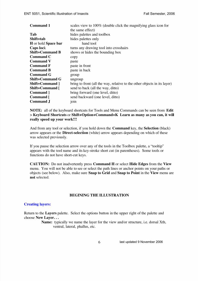
Command 1 scales view to 100% (double click the magnifying glass icon for
the same effect)Tab hides palettes and toolbox
Shift+tab hides palettes only
H or hold Space bar hand tool
Caps lock turns any drawing tool into crosshairsShift+Command B shows or hides the bounding box
Command C copy
Command V paste
Command F paste in frontCommand B paste in back
Command G group
Shift+Command G ungroup
Shift+Command ] bring to front (all the way, relative to the other objects in its layer)
Shift+Command [ send to back (all the way, ditto)
Command ] bring forward (one level, ditto)
Command [ send backward (one level, ditto)Command J join
NOTE: all of the keyboard shortcuts for Tools and Menu Commands can be seen from Edit
> Keyboard Shortcuts or Shift+Option+Command+K Learn as many as you can, it will
really speed up your work!!!
And from any tool or selection, if you hold down the Command key, the Selection (black)
arrow appears or the Direct-selection (white) arrow appears depending on which of thesewas selected previously.
If you pause the selection arrow over any of the tools in the Toolbox palette, a “tooltip”appears with the tool name and its key-stroke short cut (in parentheses). Some tools orfunctions do not have short-cut keys.
CAUTION: Do not inadvertently press Command H or select Hide Edges from the View
menu. You will not be able to see or select the path lines or anchor points on your paths orobjects (see below). Also, make sure Snap to Grid and Snap to Point in the View menu are
not selected.
BEGINING THE ILLUSTRATION
Creating layers:
Return to the Layers palette. Select the options button in the upper right of the palette and
choose New Layer. . .
Name: typically we name the layer for the view and/or structure, i.e. dorsal Xth,ventral, lateral, phallus, etc.
8/8/2019 AI Tutorial
http://slidepdf.com/reader/full/ai-tutorial 7/22
ENT 5051, Scientific Illustration of Insects Fall Semester, 2006
last updated 9 November 20067
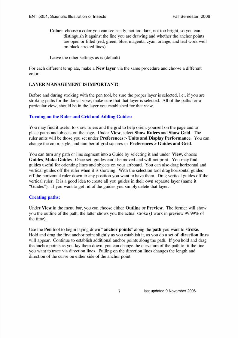
Color: choose a color you can see easily, not too dark, not too bright, so you can
distinguish it against the line you are drawing and whether the anchor pointsare open or filled (red, green, blue, magenta, cyan, orange, and teal work well
on black stroked lines).
Leave the other settings as is (default)
For each different template, make a New layer via the same procedure and choose a different
color.
LAYER MANAGEMENT IS IMPORTANT!
Before and during stroking with the pen tool, be sure the proper layer is selected, i.e., if you are
stroking paths for the dorsal view, make sure that that layer is selected. All of the paths for aparticular view, should be in the layer you established for that view.
Turning on the Ruler and Grid and Adding Guides:
You may find it useful to show rulers and the grid to help orient yourself on the page and to
place paths and objects on the page. Under View, select Show Rulers and Show Grid. The
ruler units will be those you set under Preferences > Units and Display Performance. You can
change the color, style, and number of grid squares in Preferences > Guides and Grid.
You can turn any path or line segment into a Guide by selecting it and under View, choose
Guides, Make Guides. Once set, guides can’t be moved and will not print. You may findguides useful for orienting lines and objects on your artboard. You can also drag horizontal and
vertical guides off the ruler when it is showing. With the selection tool drag horizontal guides
off the horizontal ruler down to any position you want to have them. Drag vertical guides off thevertical ruler. It is a good idea to create all you guides in their own separate layer (name it“Guides”). If you want to get rid of the guides you simply delete that layer.
Creating paths:
Under View in the menu bar, you can choose either Outline or Preview. The former will show
you the outline of the path, the latter shows you the actual stroke (I work in preview 99.99% of
the time).
Use the Pen tool to begin laying down “anchor points” along the path you want to stroke.
Hold and drag the first anchor point slightly as you establish it, as you do a set of direction lineswill appear. Continue to establish additional anchor points along the path. If you hold and drag
the anchor points as you lay them down, you can change the curvature of the path to fit the lineyou want to trace via direction lines. Pulling on the direction lines changes the length and
direction of the curve on either side of the anchor point.
8/8/2019 AI Tutorial
http://slidepdf.com/reader/full/ai-tutorial 8/22
ENT 5051, Scientific Illustration of Insects Fall Semester, 2006
last updated 9 November 20068
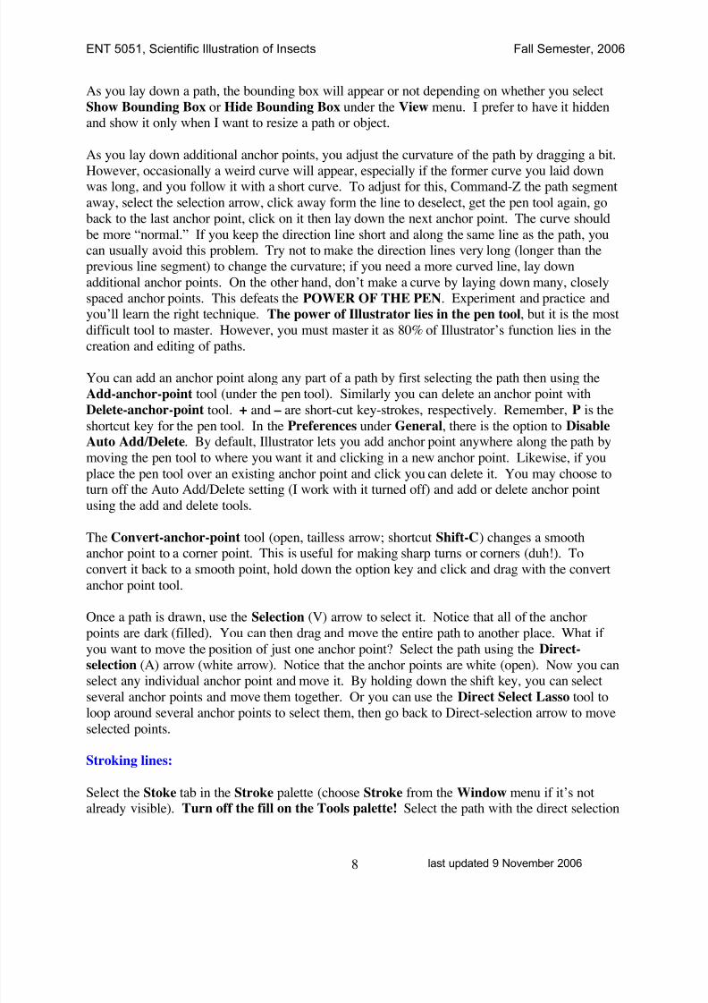
As you lay down a path, the bounding box will appear or not depending on whether you select
Show Bounding Box or Hide Bounding Box under the View menu. I prefer to have it hiddenand show it only when I want to resize a path or object.
As you lay down additional anchor points, you adjust the curvature of the path by dragging a bit.
However, occasionally a weird curve will appear, especially if the former curve you laid downwas long, and you follow it with a short curve. To adjust for this, Command-Z the path segment
away, select the selection arrow, click away form the line to deselect, get the pen tool again, go
back to the last anchor point, click on it then lay down the next anchor point. The curve should
be more “normal.” If you keep the direction line short and along the same line as the path, youcan usually avoid this problem. Try not to make the direction lines very long (longer than the
previous line segment) to change the curvature; if you need a more curved line, lay down
additional anchor points. On the other hand, don’t make a curve by laying down many, closely
spaced anchor points. This defeats the POWER OF THE PEN. Experiment and practice andyou’ll learn the right technique. The power of Illustrator lies in the pen tool, but it is the most
difficult tool to master. However, you must master it as 80% of Illustrator’s function lies in the
creation and editing of paths.
You can add an anchor point along any part of a path by first selecting the path then using the
Add-anchor-point tool (under the pen tool). Similarly you can delete an anchor point with
Delete-anchor-point tool. + and – are short-cut key-strokes, respectively. Remember, P is the
shortcut key for the pen tool. In the Preferences under General, there is the option to Disable
Auto Add/Delete. By default, Illustrator lets you add anchor point anywhere along the path by
moving the pen tool to where you want it and clicking in a new anchor point. Likewise, if you
place the pen tool over an existing anchor point and click you can delete it. You may choose toturn off the Auto Add/Delete setting (I work with it turned off) and add or delete anchor point
using the add and delete tools.
The Convert-anchor-point tool (open, tailless arrow; shortcut Shift-C) changes a smoothanchor point to a corner point. This is useful for making sharp turns or corners (duh!). To
convert it back to a smooth point, hold down the option key and click and drag with the convert
anchor point tool.
Once a path is drawn, use the Selection (V) arrow to select it. Notice that all of the anchor
points are dark (filled). You can then drag and move the entire path to another place. What if
you want to move the position of just one anchor point? Select the path using the Direct-
selection (A) arrow (white arrow). Notice that the anchor points are white (open). Now you canselect any individual anchor point and move it. By holding down the shift key, you can select
several anchor points and move them together. Or you can use the Direct Select Lasso tool toloop around several anchor points to select them, then go back to Direct-selection arrow to move
selected points.
Stroking lines:
Select the Stoke tab in the Stroke palette (choose Stroke from the Window menu if it’s notalready visible). Turn off the fill on the Tools palette! Select the path with the direct selection
8/8/2019 AI Tutorial
http://slidepdf.com/reader/full/ai-tutorial 9/22
ENT 5051, Scientific Illustration of Insects Fall Semester, 2006
last updated 9 November 20069
tool and then stroke the path at the desired line weight. I commonly use .25 pt for alveoli,
membrane, or other fine lines. 0.5, 0.75, 1 and 1.5 are for other lines. I generally do not useabove 1.5. You will need to print your drawing a few times to gauge the proper line stroke.
Indicate on a sample drawing the line stoke used for different lines and effects and use these
strokes uniformly throughout your different plates. You can change the color and opacity of the
stroke, but for line drawings, make sure they are 100% opacity and 100% black.
Under the Stroke tab, select the middle Round Cap of the cap selections and Round Join below
it. This makes your endpoints and corner points appear more like they were made with an ink
pen. In order to change the endpoints, remember that the path has to be selected.
You can also draw lines with the Pencil tool, but these are much more “freehand” in appearance
and not as controllable as the pen tool. However, in certain cases the pencil tool is essential. Set
the “tolerance” of the pencil tool by double clicking on the tool icon and adjusting the settings.Setting the tolerance at 0.5 lets you make much more squiggly lines that with it set at 20.
Experiment to get the effect you want.
Drawing “free-hand” lines:
Pencil tool—the pencil tool is used for drawing free hand lines. You can smooth, average,
simplify, or outline stroke a pencil drawn path, but the anchor points do not have direction
lines for changing angles. The pencil tool is very useful for drawing irregular lines, such asmembrane. The use of a digital palette and electronic stylus make this a more accurate
tool.
Eraser tool—the eraser tool, grouped with the pencil tool in the toolbox, lets you erase parts of
paths, but it does not work on shapes or objects. Select the path you want to erase and drag
the eraser tool over the part you want to erase. You can also use the eraser tool to cut a path(just like the scissors tool, see below) by simply clicking on that part of the select path youwant to cut.
Modifying lines:
You can smooth, roughen, or simplify lines as well as average or join anchor points or cut
segments of a path.
Smooth—use the Smooth tool under the Pencil tool. Select the path and trace along theanchor points using the Smooth tool to smoothen the path (you are actually just eliminating
anchor points).
Simplify—Select the path. Go to Object on the menu bar, then to Path, then to the pop-upwindow Simplify. . . Select Preview, then move the Curve Precision slide to see how the
path behaves. The closer to 100%, the closer to the original path shape.
Roughen—Select the path. Use the Pencil tool along the path to roughen.

8/8/2019 AI Tutorial
http://slidepdf.com/reader/full/ai-tutorial 10/22
ENT 5051, Scientific Illustration of Insects Fall Semester, 2006
last updated 9 November 200610
Join—You can only Join “endpoints,” either on the same path (which then closes the path)
or to join two separate paths. Use the Direct selection tool (white arrow) to select the path(s)then by holding down the shift key, select the endpoints to be joined. Then Object > Path >
Join.
Cut—Use the Scissors tool to cut a path into two or more segments.
Making weighted lines:
Outline stroke—This is a very useful tool to make tapered lines or to vary the thickness of aline along its length (weighted lines!). Select the stroked path. Then Object > Path >
Outline Stoke. Once the path is outlined, use the Direct-selection tool to select it again.
Then by selecting individual open anchor points (thus filling them) and dragging them, you
can change the thickness of the stroke or taper the ends. Holding down shift allows you toselect several anchor points to drag all at once. Once a path is stroked, it becomes a filled
shape and cannot be converted back to a path! Remember: if you return to the pen tool
after outlining a stroke, be sure to turn off the fill again and reset the caps.
Knife tool—This tool, docked with the scissors tool, is used to cut filled shapes. Select the
shape and drag the knife tool across the part you want to cut, then select that part and remove
it by hitting the delete key. Or, you can move the cut off part to another location. Be sure to
select the shape you want to cut; if not, everything that the knife passes will be cut.
Other very useful functions:
Dashed Lines—Select the stroked path. On the Stroke palette, select Dashed Line. Select the
Dash and Gap point size to best balance with the stroke weight. Hit the Return key to set the
point sizes selected. Record these so you use them uniformly in your plates. Decent, wellbalanced dashes and gaps for line strokes are:Line weight dash gap
0.25 pt 0.50 0.75
0.50 0.75 1.0
0.75 1.00 1.51.00 1.50 2.0
Creating exact copies of paths, shapes, or other objects—Select the path with the Selection
tool (black arrow), hold down the Option key, and click and drag an exact copy of the object.Or, select the path, then Edit, Copy (Command C), Paste in Front (Command F), and drag
the copy off the top of the original with the selection tool or move it off with the key boardarrows. Or, select the path, drag a copy with the selection tool with Option down and
position the copy in relation to the original where you want it. Then by repeatedly hittingCommand D, you Duplicate the path in the same position relative position.
Blend—Another useful tool in certain situations to insert a series of paths (or objects) between a
pair of paths (or objects) either of the same or different shapes. The blend tool “morphs” theshapes together through a series of transitions (fixed steps or fixed distances). Select the
8/8/2019 AI Tutorial
http://slidepdf.com/reader/full/ai-tutorial 11/22
ENT 5051, Scientific Illustration of Insects Fall Semester, 2006
last updated 9 November 200611
paths for “blending.” Then Object > Blend. Under Blend Options select the Specified
Steps or Specified Distance for Spacing. Then back under Blend, select Make (orOption+Command+B). You will have to experiment a bit to get the desired effect.
You can Expand the blend, Ungroup, and then move or edit individual parts with the
selection arrows.
The objects in the blend will be laid out in a straight line between the two original endpoint
oblects. If you want to fit them to a curved line, draw a curved line with the pen tool, make
sure it is on over and on top of the blend (Bring to front), select both the blend and the curve,then Object > Blend > Replace Spine. Notice the different Orientation options.
You can also blend the color between two or more objects. For example to get a highlight on
a sphere, draw a circle with the ellipse tool. Fill it with a color. Draw a small while circle on
top of it. Fill it with white. Select both. Under Object > Blend > Blend Options, select
Smooth Color.
Clipping mask—A clipping mask is an object whose shape masks another object or artwork sothat the latter fits within the borders of the mask. It is very useful for “filling” complex
objects, including text, with complex fills. See below for using clipping mask to create a
cross hatched fill.
What is nice about clipping masks is that each of the objects is fully editable. By using the
direct selection tool (white arrow) you can select individual parts of the mask and change the
color, stroke, fill etc. On the other hand, the full original objects are still present, onlymasked, so the size of the illustration is the same as the unmasked objects (look at the file in
Outline format).
Illustrating bilaterally symmetrical structures:
For bilaterally symmetrical structures you only need to draw half of the image, then reflect the
other half using Illustrator.
In the layer you want to reflect, Select All (Command A) of the individual paths you want to
duplicate. You can unlock the template and select it also, if necessary. Then Object > Group
(Command G). Go to Object again, Transform > Reflect. . . Select the Axis (usually Vertical)
and the Angle (usually 90°). You can check Preview if you wish. Then Copy. Now use thearrow keys to move the reflected image so that it aligns in the position you want or you can drag
with the selection tool and fine tune the position with the arrow keys. It might be useful to ShowBounding Box to help you align or you can use the Align palette (under Window menu) to help
you align the two images. You can then Ungroup (Shift+Command G) both sets of paths foradditional editing of individual paths.
You can run into the problem of having your reflected composite image appear too symmetrical
and hence look unnatural. To avoid this, just very slightly change the position or shape of a few
8/8/2019 AI Tutorial
http://slidepdf.com/reader/full/ai-tutorial 12/22
ENT 5051, Scientific Illustration of Insects Fall Semester, 2006
last updated 9 November 200612
paths on one side or the other to break up the symmetry. Use the direct selection tool to do this.
Here is where your artistic eye comes into play.
Making and drawing setae:
1 Draw a vertical line using the Line segment tool (hold down the shift key to force it tovertical). Stroke at 0.25 pt.
2 Select and Copy the line segment and Paste in back (Command B). Don’t move the lines at
this point!
3 Using the Direct Selection tool, drag across the apex of the line segment to select bothendpoints. Join the endpoints (Command J or Object > Path > Join).
4 Select an endpoint at the base of the line. Move it to the right with a few hits on the right
arrow key. Now select the other endpoint and move it to the left the same number of
increments. Now select those endpoints and Join them. The object is to make a perfectlysymmetrical, vertical, long, narrow triangle.
5 Fill with black or white using the Fill tool. At this point you may also want to round the
bottom of the triangle (i.e., the seta) using the direction toggles.6 Turn off fill, then draw an oval using the Ellipse tool. This will be the setal socket oralveolus.
7 Move the oval to the base of the seta and center it using the Align palette tools. Make sure
the seta is in front of the oval by using the Bring to front or Send to back option under
Object > Arrange.8 With the Selection tool select both the seta and the oval and Group them (Command G).
9 Select the Brushes palette
10 From the upper right option button, select New Brush > New Art Brush then Name thebrush (e.g., long black seta, peg-like seta, etc.) and for Direction select the upward pointing
arrow (from the base of the seta to the apex).
To stroke a seta, select the Paintbrush tool, select the setal brush you just made, and brush out aseta. You can also use the pen or pencil tools to draw a seta. Draw a line, leave it selected,
and click on the setal brush in the Brushes palette to turn it into a setae. Using the pen tool
gives you a little more control over the position, length, and direction of the seta than does
the brush tool. If using the pencil tool to do this, set the tolerance to 20.
After brushing all setae, turn off the brush by going back to the Brushes palette and click the
Remove Brush Stroke icon down at the bottom.
Putting a white shadow behind a seta:
Select the seta. Copy and Paste in Back. Under the Stroke palette, select a larger weight, 2.5 pt
works well for a 1 pt seta. Turn off the Brush tool under the Brush tab, then under Stroke,deselect Fill, and choose white for the stroke color.
CAUTION! Keep an eye on the Fill and Stroke selections on the Toolbox menu bar. If the fillis still selected your setae (or any other stroke for that matter) will also be filled. Turn the
8/8/2019 AI Tutorial
http://slidepdf.com/reader/full/ai-tutorial 13/22
ENT 5051, Scientific Illustration of Insects Fall Semester, 2006
last updated 9 November 200613
Fill off by selecting the Fill box, then select the None tool (the square with the red slash
across it). You can toggle back and forth between Fill and Stroke. Since Illustratorremembers the last action, you may end up filling something you don’t want. This is
sometimes especially a problem when the background fill is white; this causes your template
drawing to be covered by a white fill. Again, pay attention to the Fill/Stroke selection to
avoid this problem.
Fills and gradients:
Draw a shape with one of the shape tools (Ellipse, Rectangle, etc.) or a path with the Pen orPencil tool. Fills work best in closed paths, so if you draw a complex shape with the pen tool, be
sure to close it (notice that when you move the pen tool over the starting anchor point a small
circle appears. Clicking at this time will close the path.) With the Pencil tool you have to Join
the endpoints as explained above.
Select the shape, then select the Fill from the Toolbox (turn it on if it is deselected). You can
select the color from the Color palette. You can fine tune the color using the sliding controls.Or you can quickly select black or white.
Treat gradients the same way. The Gradient tool is located at the bottom of the Toolbox. You
have different options for the appearance of gradients. Explore the Gradient palette – you can
choose type of gradient (linear, radial), change the angle, color, etc.
Cross Hatching:
Crosshatching is a very useful feature for filling shapes to indicate sclerotized structures that lie
below other structures. There are several ways to make crosshatches, but the easiest is to use the
customized Crosshatch swatches. These designs are from a 3rd party Plug-in provider,Hotdoor, Inc. (http://www.hotdoor.com/index.html), and they are used mostly in architecturaldrawings. I have further customized Hotdoor’s swatches for use in illustrating insect structures.
The crosshatch swatches are saved in a separate Adobe Illustrator file called Crosshatches.ai.
To activate this swatch, quit the Adobe Illustrator application (save your work!) and locate the
Adobe Illustrator application folder on your computer’s hard drive in the Applications folder.Open the Adobe Illustrator folder and locate the Presets folder and then the Swatches folder
within it. Drag the Crosshatches.ai file into the Swatches folder, relaunch Illustrator and open
your file. To locate the crosshatch swatches palette, go to Window > Swatch Libraries >
Crosshatches. Open the options buttons and check Persistent.
Using the crosshatch swatches:
1. Draw the shape you want to fill with a crosshatch, keep the shape selected or select it. Openthe crosshatch swatch palette and click on the swatch pattern.
Using the gradient method:
8/8/2019 AI Tutorial
http://slidepdf.com/reader/full/ai-tutorial 14/22
ENT 5051, Scientific Illustration of Insects Fall Semester, 2006
last updated 9 November 200614
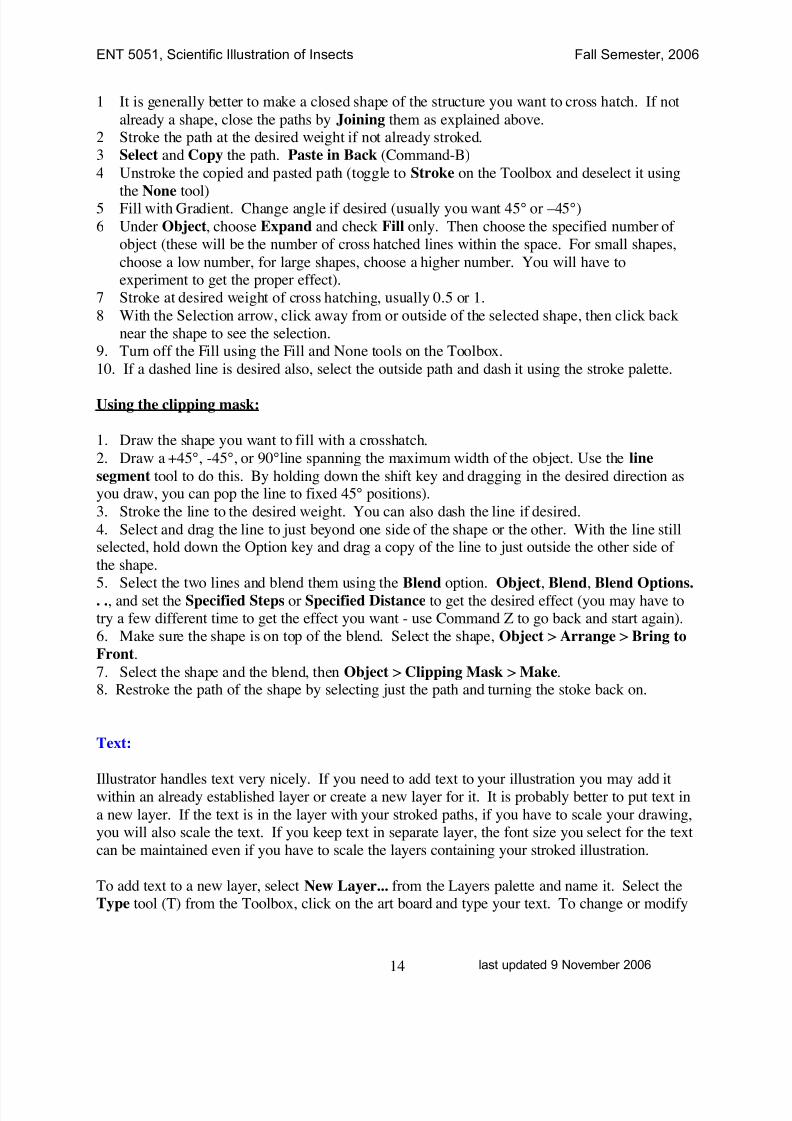
1 It is generally better to make a closed shape of the structure you want to cross hatch. If not
already a shape, close the paths by Joining them as explained above.2 Stroke the path at the desired weight if not already stroked.
3 Select and Copy the path. Paste in Back (Command-B)
4 Unstroke the copied and pasted path (toggle to Stroke on the Toolbox and deselect it using
the None tool)5 Fill with Gradient. Change angle if desired (usually you want 45° or –45°)
6 Under Object, choose Expand and check Fill only. Then choose the specified number of
object (these will be the number of cross hatched lines within the space. For small shapes,
choose a low number, for large shapes, choose a higher number. You will have toexperiment to get the proper effect).
7 Stroke at desired weight of cross hatching, usually 0.5 or 1.
8 With the Selection arrow, click away from or outside of the selected shape, then click back
near the shape to see the selection.9. Turn off the Fill using the Fill and None tools on the Toolbox.
10. If a dashed line is desired also, select the outside path and dash it using the stroke palette.
Using the clipping mask:
1. Draw the shape you want to fill with a crosshatch.
2. Draw a +45°, -45°, or 90°line spanning the maximum width of the object. Use the line
segment tool to do this. By holding down the shift key and dragging in the desired direction asyou draw, you can pop the line to fixed 45° positions).
3. Stroke the line to the desired weight. You can also dash the line if desired.
4. Select and drag the line to just beyond one side of the shape or the other. With the line stillselected, hold down the Option key and drag a copy of the line to just outside the other side of
the shape.
5. Select the two lines and blend them using the Blend option. Object, Blend, Blend Options.. ., and set the Specified Steps or Specified Distance to get the desired effect (you may have totry a few different time to get the effect you want - use Command Z to go back and start again).
6. Make sure the shape is on top of the blend. Select the shape, Object > Arrange > Bring to
Front.
7. Select the shape and the blend, then Object > Clipping Mask > Make.8. Restroke the path of the shape by selecting just the path and turning the stoke back on.
Text:
Illustrator handles text very nicely. If you need to add text to your illustration you may add itwithin an already established layer or create a new layer for it. It is probably better to put text in
a new layer. If the text is in the layer with your stroked paths, if you have to scale your drawing,you will also scale the text. If you keep text in separate layer, the font size you select for the text
can be maintained even if you have to scale the layers containing your stroked illustration.
To add text to a new layer, select New Layer... from the Layers palette and name it. Select theType tool (T) from the Toolbox, click on the art board and type your text. To change or modify
8/8/2019 AI Tutorial
http://slidepdf.com/reader/full/ai-tutorial 15/22
ENT 5051, Scientific Illustration of Insects Fall Semester, 2006
last updated 9 November 200615
font, size or style, under Window, Type, choose Character for the character palette which has
all the tools for modifying your text.
If you add text to an existing layer, make sure the correct layer is selected, then follow the same
procedure.
You can do much more with text in Illustrator than the simple labeling we usually use with
scientific illustrations.
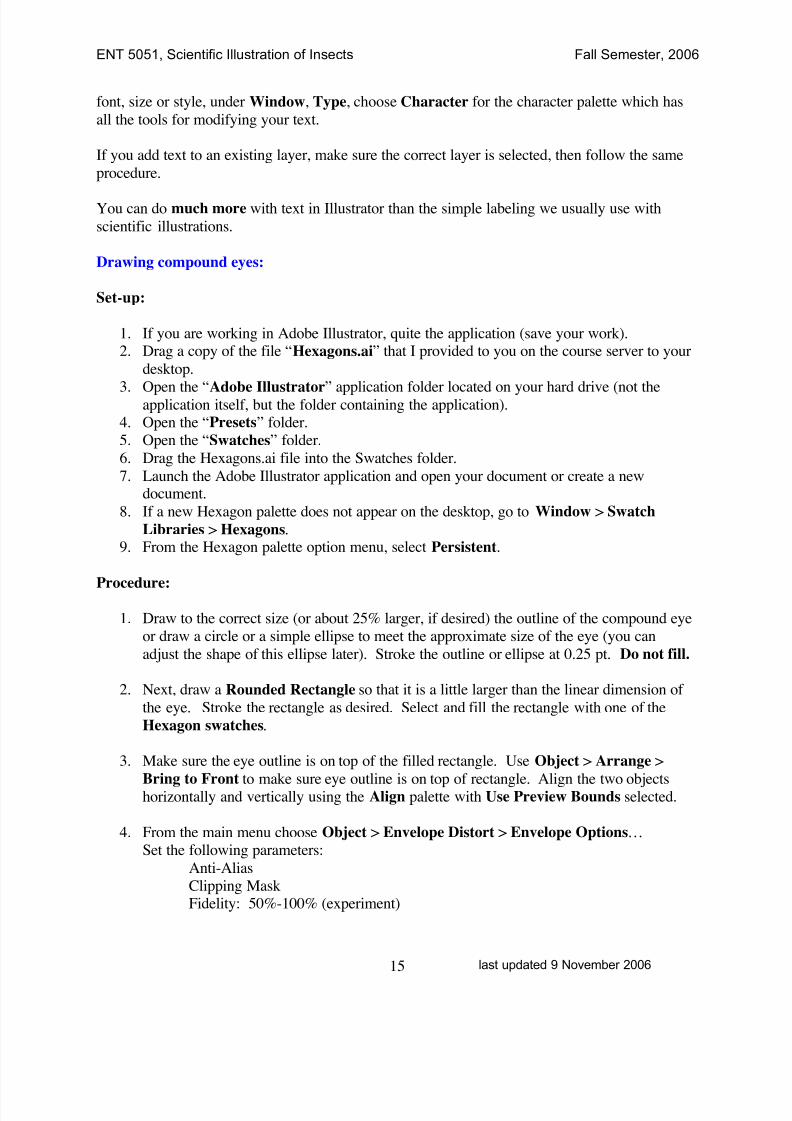
Drawing compound eyes:
Set-up:
1. If you are working in Adobe Illustrator, quite the application (save your work).2. Drag a copy of the file “Hexagons.ai” that I provided to you on the course server to your
desktop.
3. Open the “Adobe Illustrator” application folder located on your hard drive (not theapplication itself, but the folder containing the application).4. Open the “Presets” folder.
5. Open the “Swatches” folder.
6. Drag the Hexagons.ai file into the Swatches folder.
7. Launch the Adobe Illustrator application and open your document or create a newdocument.
8. If a new Hexagon palette does not appear on the desktop, go to Window > Swatch
Libraries > Hexagons.9. From the Hexagon palette option menu, select Persistent.
Procedure:
1. Draw to the correct size (or about 25% larger, if desired) the outline of the compound eye
or draw a circle or a simple ellipse to meet the approximate size of the eye (you can
adjust the shape of this ellipse later). Stroke the outline or ellipse at 0.25 pt. Do not fill.
2. Next, draw a Rounded Rectangle so that it is a little larger than the linear dimension of
the eye. Stroke the rectangle as desired. Select and fill the rectangle with one of the
Hexagon swatches.
3. Make sure the eye outline is on top of the filled rectangle. Use Object > Arrange >
Bring to Front to make sure eye outline is on top of rectangle. Align the two objectshorizontally and vertically using the Align palette with Use Preview Bounds selected.
4. From the main menu choose Object > Envelope Distort > Envelope Options…
Set the following parameters:
Anti-Alias
Clipping MaskFidelity: 50%-100% (experiment)
8/8/2019 AI Tutorial
http://slidepdf.com/reader/full/ai-tutorial 16/22
ENT 5051, Scientific Illustration of Insects Fall Semester, 2006
last updated 9 November 200616
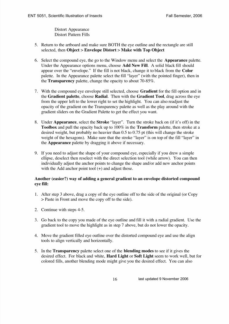
Distort Appearance
Distort Pattern Fills
5. Return to the artboard and make sure BOTH the eye outline and the rectangle are still
selected, then Object > Envelope Distort > Make with Top Object
6. Select the compound eye, the go to the Window menu and select the Appearance palette.
Under the Appearance options menu, choose Add New Fill. A solid black fill should
appear over the “envelope.” If the fill is not black, change it to black from the Color
palette. In the Appearance palette select the fill “layer” (with the pointed finger), then inthe Transparency palette, change the opacity to about 70-85%.
7. With the compound eye envelope still selected, choose Gradient for the fill option and in
the Gradient palette, choose Radial. Then with the Gradient Tool, drag across the eyefrom the upper left to the lower right to set the highlight. You can also readjust the
opacity of the gradient on the Transparency palette as well as the play around with the
gradient sliders on the Gradient Palette to get the effect you want.
8. Under Appearance, select the Stroke “layer”. Turn the stroke back on (if it’s off) in the
Toolbox and pull the opacity back up to 100% in the Transform palette, then stroke at a
desired weight, but probably no heavier than 0.5 to 0.75 pt (this will change the stroke
weight of the hexagons). Make sure that the stroke “layer” is on top of the fill “layer” inthe Appearance palette by dragging it above if necessary.
9. If you need to adjust the shape of your compound eye, especially if you drew a simpleellipse, deselect then reselect with the direct selection tool (while arrow). You can then
individually adjust the anchor points to change the shape and/or add new anchor points
with the Add anchor point tool (+) and adjust those.
Another (easier?) way of adding a general gradient to an envelope distorted compound
eye fill:
1. After step 3 above, drag a copy of the eye outline off to the side of the original (or Copy> Paste in Front and move the copy off to the side).
2. Continue with steps 4-5.
3. Go back to the copy you made of the eye outline and fill it with a radial gradient. Use the
gradient tool to move the highlight as in step 7 above, but do not lower the opacity.
4. Move the gradient filled eye outline over the distorted compound eye and use the aligntools to align vertically and horizontally.
5. In the Transparency palette select one of the blending modes to see if it gives the
desired effect. For black and white, Hard Light or Soft Light seem to work well, but forcolored fills, another blending mode might give you the desired effect. You can also

8/8/2019 AI Tutorial
http://slidepdf.com/reader/full/ai-tutorial 17/22
ENT 5051, Scientific Illustration of Insects Fall Semester, 2006
last updated 9 November 200617
adjust the opacity now. I cover blending modes in much more detail in the Photoshop
tutorials.
NOTE: The Envelope Distort function turns your objects from vectors to bitmapped (raster)
images. As such, they become resolution dependant. You will want to draw your eye to itscorrect size (or slightly larger) at the start. If you attempt to increase its size later, you will affect
the quality of the image.
NOTE: As a bitmapped image, your file will be larger. Changes and edits to the compound eyeimage will take longer to process. Be patient. Also, your illustration will also take longer to
print now that it contains a raster portion.
8/8/2019 AI Tutorial
http://slidepdf.com/reader/full/ai-tutorial 18/22
ENT 5051, Scientific Illustration of Insects Fall Semester, 2006
last updated 9 November 200618
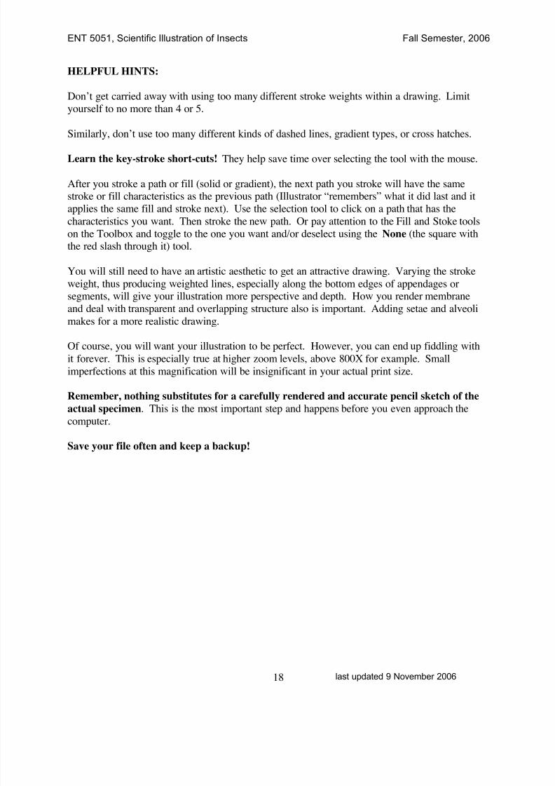
HELPFUL HINTS:
Don’t get carried away with using too many different stroke weights within a drawing. Limit
yourself to no more than 4 or 5.
Similarly, don’t use too many different kinds of dashed lines, gradient types, or cross hatches.
Learn the key-stroke short-cuts! They help save time over selecting the tool with the mouse.
After you stroke a path or fill (solid or gradient), the next path you stroke will have the samestroke or fill characteristics as the previous path (Illustrator “remembers” what it did last and it
applies the same fill and stroke next). Use the selection tool to click on a path that has the
characteristics you want. Then stroke the new path. Or pay attention to the Fill and Stoke tools
on the Toolbox and toggle to the one you want and/or deselect using the None (the square withthe red slash through it) tool.
You will still need to have an artistic aesthetic to get an attractive drawing. Varying the strokeweight, thus producing weighted lines, especially along the bottom edges of appendages orsegments, will give your illustration more perspective and depth. How you render membrane
and deal with transparent and overlapping structure also is important. Adding setae and alveoli
makes for a more realistic drawing.
Of course, you will want your illustration to be perfect. However, you can end up fiddling with
it forever. This is especially true at higher zoom levels, above 800X for example. Small
imperfections at this magnification will be insignificant in your actual print size.
Remember, nothing substitutes for a carefully rendered and accurate pencil sketch of the
actual specimen. This is the most important step and happens before you even approach thecomputer.
Save your file often and keep a backup!
8/8/2019 AI Tutorial
http://slidepdf.com/reader/full/ai-tutorial 19/22
ENT 5051, Scientific Illustration of Insects Fall Semester, 2006
last updated 9 November 200619
!!!!!!!! IF SOMETHING GOES WRONG !!!!!!!
Troubleshoot damaged files (Illustrator CS and CS2)http://www.adobe.com/support/techdocs/320318.html
What's covered
Beginning and intermediate troubleshooting
Advanced troubleshooting
This document can help you resolve errors caused by damaged Adobe Illustrator files. A damagedIllustrator file may cause an error, such as "There is not enough memory to open the Illustration" or "Acrobat PDF File Format is having difficulties...," or cause other unexpected behavior (for example,crashes, objects failing to preview) when you modify, save, or print artwork in Illustrator.
To determine if a damaged file is the cause, create a new Illustrator file and perform the same tasksthat caused the problem with the original file. If you cannot re-create the problem with the new file, theoriginal file may be damaged.
An Illustrator file may become damaged because of low disk space, low system resources, or software conflicts. In addition, if the system returns an error, freezes, or crashes while an applicationis reading from or writing to disk, the open file can become damaged. Working with a file on a networkor removable drive increases the likelihood of a communication error during the read/write process.
Beginning and intermediate troubleshooting
To repair a damaged file, create a backup copy of it on the local hard drive, and then complete one or more of the tasks in this section, in order.
1. Install the latest version of Illustrator.
Updates correct problems that are discovered after an application is released. By installing the latestupdate, you can minimize the possibility that the error is caused by a problem in the application itself.(To determine which version of Illustrator you're using, in Illustrator choose Help > About Illustrator.)The latest update for Illustrator is available from the Adobe website atwww.adobe.com/support/downloads.
-- To purchase an upgrade from Adobe, visit the Adobe Store athttp://store.adobe.com/store/products/master.jhtml?id=catIllustrator , or call Customer Services at(800) 833-6687 .
-- To locate an Authorized Reseller, visit the Adobe website athttp://partners.adobe.com/resellerfinder/na/findreseller.jsp or call Customer Services at (800) 833-6687 .
2. Copy the file to your hard drive.
If the file is on a network volume or removable disk (for example, diskette, Zip or Jaz disk), copy it toyour hard drive and open it from there.
If you purchased Illustrator as part of the Adobe Creative Suite and need to store files on a networkdrive, install and configure the accompanying Version Cue software for saving files directly to anetwork. For more information on Version Cue, see the Adobe Creative Suite product page atwww.adobe.com/products/creativesuite .
8/8/2019 AI Tutorial
http://slidepdf.com/reader/full/ai-tutorial 20/22
ENT 5051, Scientific Illustration of Insects Fall Semester, 2006
last updated 9 November 200620
3. Place the damaged Illustrator file in a new Illustrator file.
Important: This solution doesn't work if you didn't select Create Compatible PDF File in the Illustrator Native Format Options dialog box when you saved the original file. On the Macintosh platform, thedamaged Illustrator file may appear dimmed in the Place dialog box, but you will still be able to selectit and place it in the new Illustrator file.
1. In Illustrator, choose File > New.
2. Select the appropriate size and color mode, and then click OK.
3. Choose File > Place.
4. In the Place dialog box, choose All Formats from the Files of Type pop-up menu (Windows) or choose All Documents from the Show pop-up menu (Mac OS), choose the damaged file, and thenclick Place.
5. Name and save the file.
4. Copy artwork from a damaged file into a new file.
1. Open the damaged file, and then choose Object > Path > Cleanup to remove unwanted items (for example, stray points, unpainted objects, empty text paths) from the artwork.
2. If the original file contains multiple layers, choose Paste Remembers Layers from the LayersPalette pop-up menu to ensure the artwork appears on the same layers when you paste it into thenew file.
3. Using the Selection tool, drag a marquee around the artwork.
4. Choose Edit > Copy.
5. Choose File > New to create a new file.
6. In the new file, choose Edit > Paste In Front to paste the artwork in the correct position on thepage.
7. Choose File > Save.
If the new file exhibits the same behavior, it may contain a damaged object. To determine whether anobject is damaged, delete it from the new file, and then save and reopen the file and try to re-createthe problem. Repeat for each object in the file.
When you can no longer re-create the problem, delete and re-create the damaged object in theoriginal file:
-- If an Illustrator-drawn object is damaged, re-create the object with the drawing tools in Illustrator.
-- If a linked image is damaged, re-create the original image, and then replace it in your artwork.
-- If a text object is damaged, convert the text object to outlines or change its font.
To quickly change all fonts in a document:
1. Open the document in Illustrator and Choose Object > Unlock All.
8/8/2019 AI Tutorial
http://slidepdf.com/reader/full/ai-tutorial 21/22
ENT 5051, Scientific Illustration of Insects Fall Semester, 2006
last updated 9 November 200621
2. Choose Edit > Select All.
3. Choose Type > Font, and select a font not currently used in the document.
Note: To prevent text objects from becoming damaged in the future, reinstall the problematic fontfrom the original disk.
5. Delete unused swatches, custom colors, brushes, symbols, or styles.
Eliminate a problem caused by a damaged swatch, brush, symbol, or style by deleting unusedswatches, custom colors, brushes, symbols, or styles: Choose Select All Unused from the Swatchespalette menu, from the Brushes palette menu, from the Symbols palette menu, and from the Stylespalette menu, and then press Delete.
Advanced troubleshooting
The following elements can damage files: corrupt fonts, gradients, patterns, links, and objects (for example, text blocks, imported graphics, Illustrator-drawn graphics). If the tasks listed in the previoussection don't resolve the problem, you may need to repair the file by using one of the following tasks.
Note: If you repair a damaged file using one of the following tasks, you lose transparency and layer information.
6. Check for a damaged pattern, gradient, or custom color.
To determine if the problem is caused by a damaged pattern, gradient, or custom color:
1. Choose Edit > Select All and change the fill and stroke to process black.
2. Perform task 4 again to determine whether the problem occurs in a new file that does not containthe patterns, gradients, or spot colors. If the problem does not recur, re-create the pattern, gradient,or spot color in the original file.
7. Convert the file to an Adobe PDF file.
If the file is in EPS format, convert the file to PDF in Adobe Acrobat Distiller, and then open the PDFfile in Illustrator.
8. Print the file to disk as a PostScript file.
Print the Illustrator file as a PostScript file, and then open the PostScript file in Illustrator.
Note: To perform this solution you must have a PostScript printer driver installed. For information oninstalling Postscript printers in Windows XP and 2000, please see the Windows Help Menus.
1. Choose File > Print.
2. Specify the desired print or output settings.
3. Choose Adobe Postscript File from the Printer pop up menu, and then click Save.
4. Type a filename that includes a .ps extension (for example, Filename.ps), and then click OK(Windows) or Save (Mac OS).
5. Open the PostScript file in Illustrator.

8/8/2019 AI Tutorial
http://slidepdf.com/reader/full/ai-tutorial 22/22
ENT 5051, Scientific Illustration of Insects Fall Semester, 2006
9. Re-create the file in Illustrator.
Re-create the file in Illustrator after resaving or re-creating graphics, templates, and custom colorsused in the original Illustrator file. Re-create all elements copied from other Illustrator files.