AHMED MAJEED GHADHABAN -...
25
MITIGATION OF FERRESONANCE IN POWER SYSTEM AHMED MAJEED GHADHABAN UNIVERSITI TEKNOLOGI MALAYSIA
Transcript of AHMED MAJEED GHADHABAN -...
MITIGATION OF FERRESONANCE IN POWER SYSTEM
AHMED MAJEED GHADHABAN
UNIVERSITI TEKNOLOGI MALAYSIA
MITIGATION OF FERRORESONANCE IN POWER SYSTEM
AHMED MAJEED GHADHBAN
A project report submitted in partial fulfilment of the
requirements for the award of the degree of
Master of (Electrical- Power)
Faculty of Electrical Engineering
Universiti Teknologi Malaysia
JANUARY 2012

This thesis is dedicated to my beloved mother and father

ACKNOWLEDGEMENT
Particularly thanks to God for the blessing that gives me a patience and
Courage in finishing my project report. Firstly, I would like to take this
opportunity to thank ASSOC. PROF.DR AZHAR KHAIRUDDIN, my project
Supervisor for his unfailing enthusiasm and encouragement. I also would like to
thank him for all his valuable advice and assistance, suggestions and comments in
completing this project report.
I also would like to express many thanks to my parents, family and friends
for their understanding, consistent commitment and moral support in order for me to
write this project report.

ABSTRACT
The onset of a ferroresonance phenomenon in power systems is commonly
caused by the reconfiguration of a circuit into the one consisting of capacitances in
series and interacting with transformers. The reconfiguration can be due to
switching operations of de-energisation or the occurrence of a fault. Sustained
ferroresonance without immediate mitigation measures can cause the transformers
to stay in a state of saturation leading to excessive flux migrating to transformer
tanks via internal accessories. The symptom of such an event can be unwanted
humming noises being generated but the real threatening implication is the
possible overheating which can result in premature ageing and failures. The main
objective of this project is to determine the accurate models for transformers,
transmission lines, circuit breakers and cables under transient studies, particularly
for ferroresonance. The second objective is to find out methods to mitigate these
phenomena. All simulation studies are carried out using an electromagnetic
transient program, called ATP Draw. Simulation studies revealed that the key
circuit parameter to initiate transformer ferroresonance in a transmission system is
the circuit-to-circuit capacitance of a double-circuit overhead line. The extensive
simulation studies also suggested that the ferroresonance phenomena are far more
complex and sensitive to the minor changes of system parameters and circuit
breaker operations. Adding with the non-linearity of transformer core
characteristics, repeatability is not always guaranteed for simulation and
experimental studies.

ABSTRAK
Bermulanya fenomena ferosalunan dalam sistem kuasa biasanya
disebabkan oleh konfigurasi litar yang terdiri daripada kemuatan siri dan saling
tindakan dengan pengubah. Konfigurasi ini boleh disebabkan oleh operasi
pensuisan nyahtenaga atau berlakunya kerosakan. Ferosalunan mapan tanpa
langkah-langkah mitigasi segera boleh menyebabkan pengubah dalam keadaan
tepu berdepan kepada penghijrahan fluks yang berlebihan ke tangki pengubah
melalui aksesori dalaman. Gejala seperti ini boleh menjanakan bunyi berdengung
yang tidak diingini tetapi implikasi mengancam sebenar adalah pemanasan lebih
mungkin boleh mengakibatkan penuaan pra-matang dan kegagalan. Objektif utama
projek ini adalah untuk mengkaji tingkah laku ferosalunan dalam sistem kuasa dan
untuk mengetahui beberapa kaedah yang paling sesuai untuk mengurangkan
fenomena ini. Program simulasi ATP-EMTP digunakan untuk model pelbagai
komponen sistem kuasa dan mensimulasikan fenomena ferosalunan. Kaedah untuk
mengelakkan keadaan ferosalunan daripada berlaku, maka dengan itu mengelakkan
kerosakan peralatan dan kerugian juga dicadangkan berdasarkan kerja-kerja
simulasi. Talian Penghantaran 33kV digunakan dengan pengubah 33KV/100V.
Untuk memperkenalkan fenomena ferosalunan dalam sistem, suis kawalan masa
digunakan dengan pemuat bersiri. Kemudian kaedah untuk mengurangkan
fenomena ini telah dijalankan. Dalam kajian ini lima teknik yang berbeza
digunakan mengenai pengurangan ferosalunan; dengan mengubah pemuat siri,
pemuat pirau, dan rintangan kemagnetan, kemudian dengan menambah rintangan
pada bahagian sekunder pengubah dan akhir sekali dengan menukar sambungan
antara belitan utama dan sekunder pengubah.
TABLE OF CONTENTS
CHAPTER TITLE PAGE
DECLARATION ii
DEDICATION iii
ACKNOWLEDGEMENT iv
ABSTRACT v
ABSTRAK vi
TABLE OF CONTENTS vii
LIST OF TABLES xi
LIST OF FIGURES xii
LIST OF ABBREVIATIONS xv
LIST OF SYMLOLS xvi
1 INTRODUCTION 1
1.1 Introduction 1
1.2 Background of Ferroresonance 2
1.3 Types of Ferroresonance Modes 4
1.4 Symptoms of Ferroresonance 5
1.5 Objective 6
1.6 Scope of Work 6
1.7 Problem Statement 7
1.8 Organization of Project 8
2 LITERATURE REVIEW 9
2.1 Introduction 9
2.2 Theoretical Methods 10
2.3 Analog Simulation Methods 13
2.4 Real Field Test Methods 16
2.5 Laboratory Measurement Methods 18
2.6 Digital Computer Program Methods 20
2.7 Summery 24
3 METHODOLOGY 25
3.1 System Modelling 25
3.2 Description of Transmission System 26
3.3 Simulation Procedure 29
3.4 ATP-METP Simulation 30
3.5 Test System Circuit in Simulation 31
3.6 Grading Capacitor (Series Capacitor) 32
3.7 Grounding Capacitor (Shunt Capacitor) 32
3.8 Power Transformer 33
3.8.1 The an Hysteretic Curve 33
3.82 Hysteretic Curve 35
3.9 Modelling Of Magnetic Core Characteristic 36
3.10 Mathematical Modelling Magnetic Core 38
3.11 Mitigation Options Of Ferroresonance 40
3.12 Simulation Flowchart 42
3.13 Summery 43
4 SIMULATION RESULT 44
4.1 Introduction 44
4.2 Modelling Of Base Test System 45
4.3 Modelling Of Switching Circuit Breaker to Develop
Ferroresonance in system 46
4.4 Mitigation of Ferroresonance 48
4.4.1 Mitigation by Varying Series Capacitor 48

4.4.2 Mitigation by Varying Shunt Capacitor 50
4.4.3 Mitigation by Magnetizing Resistance 51
4.4.4 Mitigation by Adding Resistance in the
Secondary Side of Transformer 53
4.4.5 Mitigation by Changing the Connection
Of Transformer 55
4.5 Summery 60
5 CONCLUSION AND FURTHER WORK 61
5.1 Conclusion 61
5.2 Further Work 64
REFERENCES 65
LIST OF TABLES
TABLE NO. TITLE PAGE
3.7 The Converted data of the peak currents and peak 37
Flux linkages

LIST OF FIGURES
FIGURE NO TITLE PAGE
1.1 Linear Resonance Circuit 3
1.2 Ferroresonant circuit 4
2.1 Section of A Typical Double-Busbar 275 KV Substation 9
2.2 Model for Ferroresonance Circuit Including Line Capacitance 11
2.3 Basic Ferroresonance Circuit 12
2.4 Possible Ferroresonance Circuit 14
2.5 (A) Subharmonic Mode (B) Fundamental Mode 17
2.6 Laboratory Setup 18
2.7 400 KV Line Bays 20
2.8 Dorsey Bus Configuration with Grading Capacitors (Cg) 22
3.1 Section Of A Typical Double-Busbar 132 KV Substation 26
3.2 Reduced Equivalent Ferroresonant Circuit 27
3.3 Traction Supply Transformer Ferroresonance Arrangement 28
3.4 ATP Simulated Reduced Equivalent Ferroresonant Circuit 31
3.5 Hysteresis loop 34
3.6 Single-Phase Equivalent Circuit With Dynamic Components 35

3.8 The Saturation Curve for Nonlinear Inductor 38
3.9 Graphical View of Ferroresonance 39
3.10 Flow Chart 42
4.1 Base Test System with Circuit Breaker Study State 45
4.2 33KV System Voltages 45
4.3 Base Test System with Circuit Breaker Operation 46
4.4 System Voltages with Ferroresonance 47
4.5 System Current with Ferroresonance 47
4.6 The Voltage Output Waveform for 200pf 49
4.7 The Current Output Waveform for 200pF 49
4.8 The Voltage Output Waveform for 1nF 50
4.9 The Current output waveform for 1nF 51
4.10 The Voltage Output Waveform for RC=1.9MΩ 52
4.11 The Current Output Waveform for RC=1.9MΩ 52
4.12 Mitigation Methods by Adding Load Resistor on the Secondary 53
4.13 The Voltage Output By Load Resistor Method 54
4.14 The Current Output By Load Resistor Method 54
4.15 Y-Y Connections 55
4.16 The Voltage Output Waveform of Y-Y Connections 56
4.17 The current output waveform of Y-Y connections 56
4.18 Y-D Connections 57
4.19 The Voltage Output Waveform of Y-D Connections 57
4.20 The Current Output Waveform of Y-D Connections 58
4.21 D-Y Connections 58
4.22 The Voltage Output Waveform of D-Y Connections 59
4.23 The Current Output Waveform of D-Y Connections 59

LIST OF ABBREVIATIONS
AC - Alternating Current
ATP - Alternative Transient Program
CB - Circuit Breaker
DC - Direct Current
EMTP - Electro Magnetic Transient Program
GB - Grading Bank
HV - High Voltage
LV - Low Voltage
PT - Potential Transformer
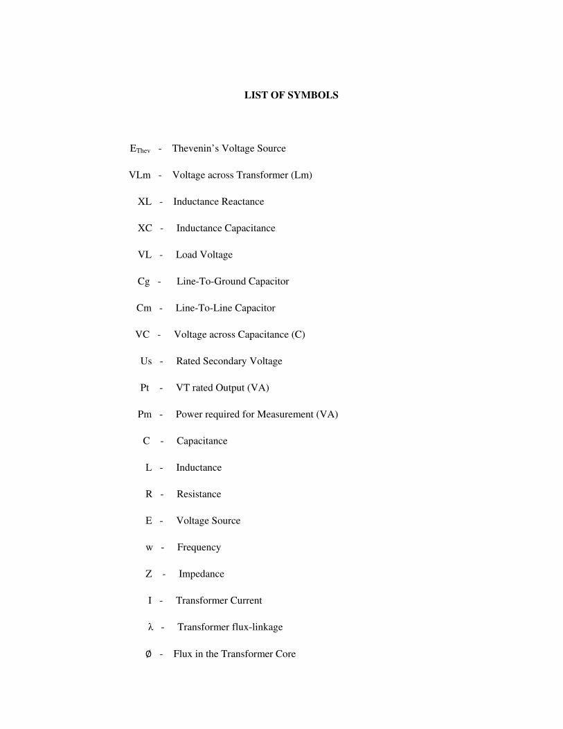
LIST OF SYMBOLS
EThev - Thevenin’s Voltage Source
VLm - Voltage across Transformer (Lm)
XL - Inductance Reactance
XC - Inductance Capacitance
VL - Load Voltage
Cg - Line-To-Ground Capacitor
Cm - Line-To-Line Capacitor
VC - Voltage across Capacitance (C)
Us - Rated Secondary Voltage
Pt - VT rated Output (VA)
Pm - Power required for Measurement (VA)
C - Capacitance
L - Inductance
R - Resistance
E - Voltage Source
w - Frequency
Z - Impedance
I - Transformer Current
λ - Transformer flux-linkage
∅ - Flux in the Transformer Core
CHAPTER 1
INTRODUCTION
1.1 Introduction
Ferroresonance refers to the resonance between network parameters with
ferromagnetic material, particularly with the presence of transformers working at
no-load conditions. It generally refers to a condition where power system voltages
resonate at the natural frequency of certain excited components within the same
system. Most of such components usually include nonlinear ironclad inductance
typical transformer windings. The capacitance must be considered for the
resonance to occur. The common sources of this include capacitor banks that are
used for voltage regulation and power factor correction.
Furthermore, a transmission line’s capacity may be a key circuit element
during a ferroresonant event. In the last 85 years, there has been research on
ferroresonance and the word itself was used in literature in 1920, even though
resonance in transformers appeared in articles as early as 1907. In practice, interest
was generated in the 1930s when it was shown that the use of series capacitors for
voltage regulation caused ferroresonance in distribution systems, resulting in
damaging the overvoltages[1].
Transient events occur due to attended power system parameters such as
resistance, inductance and capacitance of transmission line, transformer, cable,
capacitive shunt reactors, inductive shunt reactors etc. The frequency range of the
transient phenomena can extend from DC to several MHz due to such parameters
and the addition of capacitive and inductive components into the integrated power
system.
A subject of intense study, ferroresonance is also a common phenomenon
on power systems. Because of the saturated magnetizing characteristics of the bus
Potential Transformers (PT), ferroresonance may occur when switching or
disconnecting a circuit breaker at neutral-grounded substations. In the event of the
occurrence of ferroresonance, excessive voltage and current may cause the
flashover of external insulation, the burn out of PTs or the destruction of metal
oxide resistors. There has been an increase in incidences of ferroresonance in the
last few years resulting to power cuts and the destruction of PTs[2].
Magnetic saturation of the nonlinear inductance may also cause
ferroresonance. However power transformers and inductive PTs are the main
contributors to the nonlinear inductance on power systems. Under normal
conditions, a nonlinear inductance operates in the linear region of its excitation
characteristic[3].
1.2 Background of Ferroresonance
Linear resonance only occurs, for example, in the circuit in Figure 1.1
consisting of a series-connected resistor, inductor and capacitor, when the source is
tuned to the neutral frequency of the circuit. And the capacitive and inductive
reactance of the circuit is identical. The resonance frequency of any AC circuit
totally depends on its capacitance and inductance.
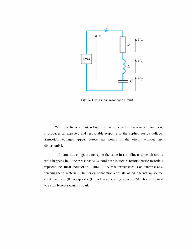
Figure 1.1: Linear resonance circuit
When the linear circuit in Figure 1.1 is subjected to a resonance condition,
it produces an expected and respectable response to the applied source voltage.
Sinusoidal voltages appear across any points in the circuit without any
distortion[4].
In contrast, things are not quite the same in a nonlinear series circuit as
what happens in a linear resonance. A nonlinear inductor (ferromagnetic material)
replaced the linear inductor in Figure 1.2. A transformer core is an example of a
ferromagnetic material. The series connection consists of an alternating source
(ES), a resistor (R), a capacitor (C) and an alternating source (ES). This is referred
to as the ferroresonance circuit.
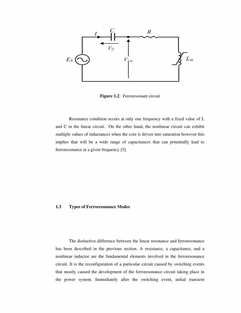
Figure 1.2: Ferroresonant circuit
Resonance condition occurs at only one frequency with a fixed value of L
and C in the linear circuit. On the other hand, the nonlinear circuit can exhibit
multiple values of inductances when the core is driven into saturation however this
implies that will be a wide range of capacitances that can potentially lead to
ferroresonance at a given frequency [5].
1.3 Types of Ferroresonance Modes
The distinctive difference between the linear resonance and ferroresonance
has been described in the previous section. A resistance, a capacitance, and a
nonlinear inductor are the fundamental elements involved in the ferroresonance
circuit. It is the reconfiguration of a particular circuit caused by switching events
that mostly caused the development of the ferroresonance circuit taking place in
the power system. Immediately after the switching event, initial transient
overvoltage will firstly occur and this is followed by the next phase of the transient
where the system may arrive at a more steady condition. There can be several
steady state ferroresonance responses randomly[6-7] induced into a system owing
to the non-linearity of the ferroresonance circuit. Basically, there are four types of
steady-state responses a ferroresonance circuit can possibly have. These includes:
the fundamental mode, sub harmonic mode, quasi-periodic mode and chaotic
mode.
1.4 Symptoms of Ferroresonance
There are various forms of ferroresonance with different physical and electrical
displays [8]. Some have very high voltages and currents while others have voltages
that are near to normal. This section demonstrates a few indications of
ferroresonance:
I. Audible Noise
II. Overheating
III. Arrester and Surge Protector Failure
IV. Flicker
V. Cable Switching
1.5 Objectives
The main objectives of this project are:
I. Examine the effects of ferroresonace in power systems.
II. To mitigate the effects of ferroresonace through system equivalent
simulation model.
III. Find out different techniques to minimize the Ferroresonance
1.6 Scope of Work
The scope of this project includes various phases which include:
I. The study of resonance and its effects in linear circuits
II. Behaviour of ferroresonance in power systems
III. Operational characteristics of a transformer in saturation
IV. Obstacles of ferroresonance in real power system and its damages
V. Study of previously work done for ferroresonance mitigation and their outputs
VI. Comparison of different techniques used for ferroresonance mitigation in
previously work done in power system.

1.7 Problem Statement
The ferroresonance phenomenon in power systems is mostly due to the
conformation of a circuit that includes capacitances in series and connected with
transformers. The conformation can be because of switching operations of de-
energisation or due to a fault. Ferroresonance without rapid mitigation can affect
the transformers to keep in a state of saturation lead to high flux to damage the
transformer tanks via internal components. Algorithmic system method of
choosing a proper simulation model is not more common yet. There is need of
practical techniques for most rapid results so that this behavior of power
components should be brought into steady-state operation for safety of high cost
power devices. So, the main goal in this project is to achieve the following
objectives:
I. To convey good information about the technical parameters on each of the
power system part needed for the simulation modelling for ferroresonance
study.
II. To facilitate some modelling road maps that needed for selecting any of the
suitable models.
III. To discover the types of models better and easy for the simulation to
mitigate the ferroresonance from the system.
1.8 Organization of Report
The report consists of five chapters.
Chapter 2 illustrates the previous work done related on ferroresonance
phenomenon in voltage transformers and power transformers. Detail of
ferroresonance behaviour in power system is also explained. Besides this, it also
includes some techniques for avoiding or mitigation of ferroresonance.
Chapter 3 describes the methodology of project simulation. Selection of
system components as well design parameters is explained. It consists of how the
simulation will be done. Basic design of ferroresonant circuit and mathematical
formulation is shown. Brief details of simulation software ATP/EMTP is also
presented. It presents the circuits that were used in the simulation and
explains how the simulations techniques are implemented.
Chapter 4 presents the results of simulation done on basic ferroresonant
model.
Lastly chapter 5 describes the conclusion and future work that is related to
the project done.
REFERENCES
1 Hui.M. and Liu.C.X. (2010). Effect of power frequency excitation character
on ferroresonance in neutral-grounded system. Chinese Physics B. 19(12).p
224-256.
2 Simha. V. and. Lee. W. J (2008). The jump phenomena - Investigation of a
sudden overvoltage incident due to ferroresonance. Ieee Industry
Applications Magazine. 14(5). p. 53-59.
3 Moradi. M. and Gholami. A. (2011). Numerical and experimental analysis
of core loss modeling for period-1 ferroresonance. European Transactions
on Electrical Power. 21(1): p. 18-26.
4 JOHN HILEY, KEITH BROWNAND IAN McKENZIE SMITH. (2008).
Electrical and Electronics Technology, Longman imprint 1960, tenth
edition
5 Cadick Corporation. (2002). “Ferroresonance” TECHNICAL BULLETIN-
004a.
6 Charalambous. C.; Osborne .Z.D.W. M. and Jarman. P. (2008). Sensitivity
studies onpower transformer ferroresonance of a 400 kV double circuit.
7 Val Escudero. M. and Redfem. M. (2004). Understanding
ferroresonancePresented at the International Conference on Power Systems
Transients (IPST’07) in Lyon, France on June 4-7, 2004.
8 Garikoitz Buigues i.z.; Victor Valverde, Angel javier mazón, josé ignacio
san martín.(2007). Ferroresonance in three-phase power distribution
transformers:sources, Consequences And Prevention.
9 Z. Emin, B. A. T. Al Zahawi, T. Yu Kwong, and M.
gur.(2001).Quantification of the chaotic behavior of ferroresonant voltage
transformer circuits. Circuits and Systems I: Fundamental Theory and
Applications, IEEE Transactions. Vol(2), 48, pp. 757-760.
10 Z. Emin, B. A. T. Al Zahawi, and Y. K. Tong.(1999). Voltage transformer
ferroresonance in 275 kV substation," in High Voltage Engineering.
Eleventh International Symposium on (Conf. Publ. No. 467). vol (1). pp.
283-286.
11 Emin, K.M.a.Z.(2009). Impact of initial conditions on the initiation of
ferroresonance," International Journal of Electrical Power & Energy
Systems.
12 Z. Emin, B. A. T. Al Zahawi, T. Yu Kwong, and M. Ugur.(2001).
Quantification of the chaotic behavior of ferroresonant voltage transformer
circuits. Circuits and Systems I: Fundamental Theory and Applications,
IEEE Transactions on. vol. 48, pp. 757-760.
13 Mozaffari S. S.H.; and Soudack. A. C.(1995). Chaotic Feroresonance in
Power Transformers," IEEE Proceeding Generation. Transmission and
Distribution. Vol(2),142: p. 247-250.
14 Mozaffari.S.S.H. and Soudack A. C.(1997). Effect of Initial Conditions on
Chaotic Ferroresonance in Power Transformers," IEEE Proceeding
Generation. Vol(1),144: p. 456 - 460.
15 Hopkinson. R. H.(1965). Ferroresonance During Single-Phase Switching of
3-Phase Distribution Transformer Banks. power apparatus and systems.
Vol(3)84: p. 289-293.
16 Hopkinson. R. H.(1968). Ferroresonant Overvoltage Control Based on
TNA Tests on Three-Phase Wye-Delta Transformer Banks. power
apparatus and systems. PAS-87: p. 352-361
17 TR(E). T.R.(2001). Ferroresonance Tests on Brinsworth-Thorpe Marsh 400
kV Circuit.
18 Young. R.L.S. and Fergestad. P. I. (2007). A Laboratory Investigation of
Ferroresonance in Cable-Connected Transformers. PAS-87: p. 1240-1249.
19 Escudero. I.D.a.M.A.R.(2005). Characterization of Ferroresonant Modes in
HV Substation with CB Grading Capacitors. International Conference on
Power Systems. p. IPST05 - 146.
20 David A. N.and Jacobson. M.(2007). EEE, Examples of Ferroresonance in
aHigh Voltage Power System. IEEE.
21 Emin, Z. et al.(2001). Quantification of the chaotic behavior of
ferroresonant voltage transformer circuits. Ieee Transactions on Circuits
and Systems I-Fundamental Theory and Applications. 48(6): p. 757-760.
22 Tran quoc. t. s.l.d.; Pham van d.; Nguyen khac. n. and tran did. l.(1998).
Temporary overvoltages in the vietnam 500 kv transmission line.IEEE.
23 Tran-Quoc. T. ; Montmeat. A. and A. Giard.(1995). Harmonic
overvoltages in industrial power system with capacitors and saturated
transformers. 3( in Industry Applications Conference,): p. 2206-
2210.IEEE.
24 T. Tran-Quoc and L. Pierrat, "Influence of Random Variables on Protective
Current Transformer Transient Performance," in First International
Conference on DigitalPower System Simulators (ICDS 95') College
Station, Texas, USA, April 5-7,1995.
25 T. Tran-Quoc and L. Pierrat, "An efficient non linear transformer model
and its
application to ferroresonance study," Magnetics, IEEE Transactions on,
vol. 31, pp. 2060-2063, 1995..